EP3214493B1 - Lens limiting assembly, camera body, and camera - Google Patents
Lens limiting assembly, camera body, and camera Download PDFInfo
- Publication number
- EP3214493B1 EP3214493B1 EP15853756.3A EP15853756A EP3214493B1 EP 3214493 B1 EP3214493 B1 EP 3214493B1 EP 15853756 A EP15853756 A EP 15853756A EP 3214493 B1 EP3214493 B1 EP 3214493B1
- Authority
- EP
- European Patent Office
- Prior art keywords
- lens
- limiting
- assembly
- ring
- elastic
- Prior art date
- Legal status (The legal status is an assumption and is not a legal conclusion. Google has not performed a legal analysis and makes no representation as to the accuracy of the status listed.)
- Active
Links
Images


Classifications
-
- G—PHYSICS
- G03—PHOTOGRAPHY; CINEMATOGRAPHY; ANALOGOUS TECHNIQUES USING WAVES OTHER THAN OPTICAL WAVES; ELECTROGRAPHY; HOLOGRAPHY
- G03B—APPARATUS OR ARRANGEMENTS FOR TAKING PHOTOGRAPHS OR FOR PROJECTING OR VIEWING THEM; APPARATUS OR ARRANGEMENTS EMPLOYING ANALOGOUS TECHNIQUES USING WAVES OTHER THAN OPTICAL WAVES; ACCESSORIES THEREFOR
- G03B17/00—Details of cameras or camera bodies; Accessories therefor
- G03B17/02—Bodies
- G03B17/12—Bodies with means for supporting objectives, supplementary lenses, filters, masks, or turrets
- G03B17/14—Bodies with means for supporting objectives, supplementary lenses, filters, masks, or turrets interchangeably
-
- F—MECHANICAL ENGINEERING; LIGHTING; HEATING; WEAPONS; BLASTING
- F16—ENGINEERING ELEMENTS AND UNITS; GENERAL MEASURES FOR PRODUCING AND MAINTAINING EFFECTIVE FUNCTIONING OF MACHINES OR INSTALLATIONS; THERMAL INSULATION IN GENERAL
- F16M—FRAMES, CASINGS OR BEDS OF ENGINES, MACHINES OR APPARATUS, NOT SPECIFIC TO ENGINES, MACHINES OR APPARATUS PROVIDED FOR ELSEWHERE; STANDS; SUPPORTS
- F16M13/00—Other supports for positioning apparatus or articles; Means for steadying hand-held apparatus or articles
- F16M13/02—Other supports for positioning apparatus or articles; Means for steadying hand-held apparatus or articles for supporting on, or attaching to, an object, e.g. tree, gate, window-frame, cycle
-
- G—PHYSICS
- G02—OPTICS
- G02B—OPTICAL ELEMENTS, SYSTEMS OR APPARATUS
- G02B7/00—Mountings, adjusting means, or light-tight connections, for optical elements
- G02B7/02—Mountings, adjusting means, or light-tight connections, for optical elements for lenses
- G02B7/021—Mountings, adjusting means, or light-tight connections, for optical elements for lenses for more than one lens
-
- G—PHYSICS
- G03—PHOTOGRAPHY; CINEMATOGRAPHY; ANALOGOUS TECHNIQUES USING WAVES OTHER THAN OPTICAL WAVES; ELECTROGRAPHY; HOLOGRAPHY
- G03B—APPARATUS OR ARRANGEMENTS FOR TAKING PHOTOGRAPHS OR FOR PROJECTING OR VIEWING THEM; APPARATUS OR ARRANGEMENTS EMPLOYING ANALOGOUS TECHNIQUES USING WAVES OTHER THAN OPTICAL WAVES; ACCESSORIES THEREFOR
- G03B2217/00—Details of cameras or camera bodies; Accessories therefor
- G03B2217/002—Details of arrangement of components in or on camera body
Definitions
- the present disclosure relates to a lens limiting assembly, a camera body comprising the lens limiting assembly, and a camera comprising said camera body.
- a camera includes a lens and a body in a fixed or detachable connection. To ensure the stabilization of imaging, it is desired to keep the flange focal distance from the lens to an image sensor as precise as possible, so that the imaging will be stable and clear.
- the existing camera lens is assembled in such a way that the lens is rotatably mounted to a camera body and hooked by a lens assembly ring on the body, and then a lens release button assembly is additionally arranged at the lens assembly ring and inserted into the lens to prevent the lens from falling off.
- the lens can rotate, a gap of about 0.05 mm is generally present, but if the camera is used on a vibrating platform, it will lead to poor contact, or even a failure, between the contact at the back and the camera lens; and in addition, the lens may also have a slightly changed flange focal distance due to the gap.
- Designers have proposed to eliminate the above-mentioned gap using a spring piece, however, the spring piece is not stable enough to guarantee a close fit.
- US 4 659 203 A describes an interchangeable lens unit that is detachably attachable to a camera main body through an improved bayonet arrangement which includes three sets of corresponding bayonet claws, one of the corresponding bayonet claws of each set being provided on a mount member of the lens unit and the other on a mount member of the camera main body.
- the bayonet claws of the three sets are formed, in mutual dimension and dispositions thereof, such that the corresponding bayonet claws of one of the sets engage one another at an upper peripheral part of the mount members immediately above the center of the mount members and the corresponding bayonet claws of the remaining two sets engage one another respectively at lateral side peripheral parts of the mount members diametrically opposite to one another with respect to the center of the mount members in the lateral direction, when the camera main body and the lens unit attached thereto are viewed from their front with the camera main body held in a normal erect state.
- the camera main body is provided with a spring member which can urge the bayonet claws on the mount member of the lens unit.
- GB 2 241 068 A describes a mount assembly having mounts which are provided on optical devices to be detachably attached to each other and which have mount surfaces which come into contact with each other when the optical devices are attached to each other wherein at least one of the mounts includes in combination a mount body which is made of synthetic resin and which is provided with the mount surface and a reinforcing metal ring member.
- An elastically deformable ring member may be present in this document.
- US 2008/075454 A1 describes an interchangeable lens selectively mountable to a first-type camera body and a second-type camera body, the first-type camera body including a first mount ring to which the interchangeable lens is mountable, the second-type camera body including a second mount ring to which the interchangeable lens is mountable, an outer diameter of the second mount ring being smaller than an outer diameter of the first mount ring.
- the interchangeable lens includes an annular packing made of a resilient material. An inner peripheral surface of the annular packing is positioned radially outside the second mount ring when the interchangeable lens is mounted to the second-type camera body. The inner peripheral surface of the annular packing is positioned radially inside an outer peripheral surface of the first mount ring when the interchangeable lens is mounted to the first-type camera body.
- the main technical problem to be solved by the embodiments of the present disclosure is to provide a lens limiting assembly which can lock a lens to prevent the lens from rotating or falling off in an axial direction.
- Another technical problem to be solved by the embodiments of the present disclosure is to provide a camera body which has said lens limiting assembly and can lock a lens to prevent the lens from rotating or falling off in an axial direction.
- a further technical problem to be solved by the embodiments of the present disclosure is to provide a camera having said body.
- the present invention relates to a lens limiting assembly according to independent claim 1, to a camera body according to claim 8, and to a camera according to claim 14.
- Preferred embodiments are described dependent claims 2 to 7, 9 to 13, and 15.
- the embodiments of the present disclosure provide a lens limiting assembly for limiting a lens which is provided with a snapping body on an outer side thereof, said lens limiting assembly comprising: an elastic element; a lens assembly ring which is arranged on said elastic element, wherein said snapping body is snapped below the elastic element when said lens is assembled into said lens assembly ring; and a locking ring which is rotatably arranged outside the lens assembly ring, wherein the locking ring abuts against and presses said elastic element when said locking ring rotates in one direction so that said elastic element presses said snapping body of the lens so as to lock the lens.
- the embodiments of the present disclosure provide a camera body, comprising a fixing frame and the lens limiting assembly according to the first aspect, said fixing frame having a contact base mounting position; said lens limiting assembly being arranged at said contact base mounting position; said lens limiting assembly being used to limit a lens, and said lens being provided with a snapping body on the outer side thereof.
- the embodiments of the present disclosure provide a camera comprising a lens and the camera body of the second aspect.
- the lens limiting assembly provided in the embodiments of the present disclosure is arranged with a locking ring; when the locking ring is screwed on, the elastic element is pressed to tightly press the snapping body of the lens, so as to lock the lens to prevent the lens from rotating and falling off in an axial direction.
- the lens and the body can be locked to prevent the lens from rotating and falling off in an axial direction.
- the first preferred embodiment of the embodiments of the present disclosure provides a camera 300; said camera 300 may be an ordinary camera with a detachable lens, a single-lens reflex camera, or a camera for a special purpose, e.g., an aerial camera for an unmanned aerial vehicle.
- said camera 300 comprises a lens 310, a camera body 200 and a lens limiting assembly 100, and said lens 310 is mounted in said camera body 200 by means of said lens limiting assembly 100.
- Said lens 310 comprises a lens cone 312, wherein an assembly part 313 is arranged at a bottom end of said lens cone 312, and three snapping bodies 314 spaced apart from each other are arranged on an outer wall of said assembly part 313 and are used to cooperate with said lens limiting assembly 100.
- said camera body 200 comprises a fixing frame 210, and said lens limiting assembly 100 is arranged in said fixing frame 210.
- Contacts 215 are arranged in said fixing frame 210 and are electrically connected to a driver or the like in the lens 310 when the lens 310 is fastened and assembled.
- Said fixing frame 210 is provided with a plurality of contact base mounting positions 220 for assembling said lens 310.
- Said fixing frame 210 is further provided with a locating pin 230, four bolts 240 and a telescopic limiting structure 250.
- said locating pins 230, said bolts 240 and said snapping bodies 314 are not limited to the above numbers, and can be designed according to practical requirements.
- said limiting structure 250 comprises a press key 251, a limiting boss 253, a first elastic member 255 and a second elastic member 257.
- the press key 251 is connected to the limiting boss 253, the first elastic member 255 is arranged between the press key 251 and the limiting boss 253, and the second elastic member 257 is sheathed on the limiting boss 253.
- the press key 251 is movably arranged on a side surface of the camera body 200, so as to facilitate the pressing by a user.
- the press key 251 comprises a key body 2511 and two snapping parts 2515 arranged on the key body 2511.
- the key body 2511 is a substantially cuboid structure comprising a first surface 2512 and a second surface 2513 arranged oppositely. Said first surface 2512 is close to said limiting boss 253, while said second surface 2513 is far away from said limiting boss 253.
- Said two snapping parts 2515 are formed by two sides of said first surface 2512 extending perpendicularly in the direction away from said first surface 2512, and are arranged spaced apart from each other, and said second surface 2513 is used to facilitate the pressing by a user to control the press key 251.
- Each snapping part 2515 comprises a first snapping arm 2516 and a second snapping arm 2519 which are integrally arranged.
- a first inclined surface 2517 is formed at one side of said first snapping arm 2516. In this embodiment, the first inclined surface 2517 inclines from the first surface 2512 of the key body 2511 in the direction away from the first surface 2512, i.e.
- the first snapping arm 2516 further comprises a surface 2518 opposite to the first inclined surface 2517, and in this embodiment, the surface 2518 is a planar surface.
- the second snapping arm 2519 is arranged at the end of the first snapping arm 2516 opposite to the first surface 2512, and is arranged substantially parallel to the first surface 2512.
- the second snapping arm 2519 comprises a clamping edge 2510, the clamping edge 2510 is formed by extending the side of the first inclined surface 2517 opposite to the first surface 2512 downward in a direction parallel to the first surface 2512.
- a snapping space 2514 is formed between the clamping edge 2510 and the first inclined surface 2517 to snap the limiting boss 253.
- the limiting boss 253 can be movably arranged in the camera body 200, and used to relatively limit the lens 310.
- the limiting boss 253 comprises a post 2531, a bracket 2533 and a shaft 2535.
- the post 2531 and the shaft 2535 are arranged at two opposite sides of the bracket 2533.
- the bracket 2533 is of a substantially inverted L-shaped structure, and comprises a first supporting part 2536 and a second supporting part 2537 which are arranged substantially perpendicular to each other.
- the post 2531 is vertically arranged on the first supporting part 2536, and the shaft 2535 is vertically arranged on the other side of the first supporting part 2536 opposite to the post 2531 and on the same straight line as the post 2531.
- the second supporting part 2537 is arranged parallel to a key body 2511 of the press key 251. Portions are removed by cutting inwardly from both sides of the middle lower position of said second supporting part 2537, so as to form two limiting ends 2538 at two sides of the second supporting part 2537 and a support end 2539 between the two limiting ends 2538.
- Each of said limiting ends 2538 comprises an upper boss 2538a and a lower boss 2538b which are arranged to protrude relative to the support end 2539.
- a second inclined surface 2538c is formed on said lower boss 2538b. Said second inclined surface 2538c has an inclination matched with that of said first inclined surface 2517.
- an outer wall of the fixing frame 210 is provided with a first assembly hole 216 facing inwards.
- the lens limiting assembly 100 comprises a lens limiting ring 20 and the lens limiting ring 20 is provided on the fixing frame 210.
- the lens assembly ring 20 is provided with a second assembly hole 217 at the side thereof facing the lens 310.
- the press key 251 and the first elastic member 255 pass through the first assembly hole 216 and are received in said camera body 200, and the limiting boss 253 and the second elastic member 257 pass through said second assembly hole 217 and are received in said camera body 200.
- the interior of the first assembly hole 216 is in communication with the interior of the second assembly hole 217, so that the press key 251, the first elastic member 255, the limiting boss 253 and the second elastic member 257 are assembled with each other.
- a mounting column 2171 is formed in the interior of the second assembly hole 217, stepped surfaces 2173 are formed at two sides of the mounting column 2171, and the mounting column 2171 is further provided in the centre thereof with a via hole 2174 through which said shaft 2535 can pass to prevent the limiting boss 253 from deviating.
- the support end 2539 of the limiting boss 253 is accommodated between two snapping parts 2515 of the press key 251, the first snapping arm 2516 of each of said snapping parts 2515 passes through each of said limiting ends 2538, the first inclined surfaces 2517 of said first snapping arms 2516 respectively abut against the second inclined surfaces 2538c of the lower bosses 2538b of the limiting boss 253, the clamping edge 2510 clamps to the lower boss 2538b, the first elastic member 255 is elastically abutted between the first surface 2512 of the key body 2511 and the support end 2539, and the second elastic member 257 is sheathed on the shaft 2535, with one end thereof abutting against the first supporting part 2536 and the other end abutting against the stepped surface 2173.
- said second inclined surface 2538c and said first inclined surface 2517 are fitted with each other, and the acting force along the first inclined surface 2517 can be decomposed into a pushing force perpendicular to the key body 2511 and a downward pressure parallel to the key body 2511.
- the pushing force presses the first elastic member 255 toward the support end 2539, and the downward pressure acts on the second inclined surface 2538c and drives the limiting boss 253 to move downward so as to in turn compress said second elastic member 257 and release same from said lens 310; and when the user no longer presses the press key 251, the first elastic member 255 and the second elastic member 257 recovers from the deformation and drives the press key 251 to rebound while driving the post 2531 to snap into the lens 310 to prevent the lens 310 from rotating.
- the clamping edge 2510 clamps to the lower boss 2538b to prevent the press key 251 from excessively rebounding and releasing from the first assembly hole 216.
- Said lens limiting assembly 100 is used to lock said lens 310 and prevent the lens 310 from rotating or falling off of said camera body 200 in an axial direction.
- said lens limiting assembly 100 comprises an elastic element 10, a lens assembly ring 20 and a locking ring 30.
- Said lens assembly ring 20 is arranged on said elastic element 10 and is accommodated in said locking ring 30, and said locking ring 30 can rotate relative to said lens assembly ring 20.
- Said elastic element 10 comprises an elastic body 11 and a plurality of elastic arms 12 on said elastic body 11.
- said elastic body 11 is an annular spring piece
- the number of said elastic arms 12 is three
- said three elastic arms 12 are arranged apart from each other at the inner side of said elastic body 11.
- each of said elastic arms 12 is formed by extending the inner side of said elastic body 11 downward in the direction of the axis of said elastic body 11.
- Said elastic arm 12 comprises a first end 121 and a second end 123, with the position of said first end 121 in the direction of the axis of said elastic body 11 being higher than the position of said second end 123 in the direction of the axis of said elastic body 11, so that a gap 13 is formed between said elastic arm 12 and said elastic body 11 to accommodate the element of said locking ring 30.
- Said elastic body 11 is further provided with a first locating hole 14 and a snapping opening 16.
- said snapping opening 16 is formed by recessing the outer wall of said elastic body 11 inwardly, and the shape of said snapping opening 16 is adapted to said limiting structure 250 of said camera body 200 so as to be nested and snapped in said limiting structure 250.
- Said lens assembly ring 20 comprises a first end face 21 and a second end face 23 which are arranged oppositely, said first end face 21 being arranged to face said elastic element 10, and said second end face 23 being arranged to face away from said elastic element 10.
- said first end face 21 is provided with a second locating hole 211, and said second locating hole 211 is joined in series with said first locating hole 14 through a locating pin 230 of said camera body 200.
- the locating pin 230 on said camera body 200 passes through said first locating hole 14 and said second locating hole 211 so as to fix said elastic element 10 and lens assembly ring 20 on said camera body 200.
- Three receiving grooves 213 spaced apart from each other are further recessed on said first end face 21 to receive the elements on said locking ring 30.
- Said second end face 23 is provided with an assembly hole 231 which penetrates through said first end face 21 and said second end face 23, and a limiting boss 253 of said camera body 200 passes through said assembly hole 231 to locate said lens 310.
- Said second end face 23 is further provided with four bolt holes 233. Said four bolt holes 233 are used to allow four bolts 240 on said camera body 200 to pass through so as to fix said lens assembly ring 20 to said camera body 200.
- the inner wall of said lens assembly ring 20 is a smooth surface, and is provided with three limiting parts 25 protruding towards the inner side and spaced apart from each other, with a mounting part 27 being formed between every two of said limiting parts 25 so that the snapping body 314 of said lens 310 can pass therethrough and being mounted in said camera body 200.
- Said locking ring 30 comprises a body 31, a hook 33 and an anti-slip part 35, said hook 33 and said anti-slip part 35 being arranged at the inner and outer sides of said body 31.
- Said body 31 is of a circular ring structure, and said circular ring has a diameter larger than that of said lens assembly ring 20 so as to receive said lens assembly ring 20 therein.
- Said hook 33 is formed by protruding inwardly from the inner side of said body 31, and in this embodiment, said hook 33 is substantially L-shaped and comprises a connecting part 331 and a bent part 333 which are integrally arranged.
- Said connecting part 331 is connected to the inner wall of said body 31, and one end of said bent part 333 is connected to said connecting part 331, and the other end thereof extends straightly.
- the end of said bent part 333 extends toward the side close to said elastic arm 12 to form a flange 335 which is used to abut against the elastic arm 12 of said elastic element 10.
- an inclined surface 334 is formed at the side of said flange 335 facing said connecting part 331 to connect said bent part 333 to said flange 335.
- said elastic element 10 is nested and snapped on said limiting structure 250 through said snapping opening 16, said lens assembly ring 20 is accommodated on said locking ring 30 and arranged on said elastic element 10, and said locating pin 230 passes through the first locating hole 14 of said elastic element 10 and the second locating hole 211 of said lens assembly ring 20 so as to connect said elastic element 10 and said lens assembly ring 20 in series; said limiting structure 250 passes through the assembly hole 231 of said lens assembly ring 20 and can stretch and retract in the direction in which said limiting structure 250 protrudes, so as to locate said lens 310; and said locking ring 30 is rotatably arranged on the outer side of said lens assembly ring 20, and said hook 33 is received in said receiving groove 213 and abuts against the elastic arm 12 of said elastic element 10.
- said locking ring 30 rotates in the opposite direction, said flange 335 of the hook 33 slides from said first end 121 of the elastic arm 12 to said second end 123 to in turn release said elastic arm 12, so that said lens 310 is no longer locked to said camera body 200, and then said lens 310 can be taken out from said camera body 200.
- said shape of said flange 335 of the hook 33 is not limited to that shown in the above figures of the embodiments, provided that the height is greater than the distance between said first end 121 of the elastic arm 12 and said elastic body 11.
- said lens assembly ring 20 is not limited to being fixed to said camera body 200 by means of a bolt hole and a bolt, and can also be fixed by way of adhesion.
- the second preferred embodiment of the present disclosure provides a lens limiting assembly 500, the lens limiting assembly 500 comprising an elastic element 510, a lens assembly ring 520 and a locking ring 530.
- the lens assembly ring 520 is arranged on the elastic element 510, the lens assembly ring 520 is accommodated in the locking ring 530, and the locking ring 530 is rotatable relative to the lens assembly ring 520.
- the elastic element 510 is an annular spring piece, and three elastic arms 512 spaced apart from each other extend from the inner side of the spring piece.
- the elastic element 510 is provided with a first locating hole 514 and a snapping opening 516.
- the snapping opening 516 is provided inwardly from the outer wall of the elastic element 510 and is of a semi-circular shape.
- a second locating hole 528 is provided on the end face of the lens assembly ring 520 facing the elastic element 510, and the second locating hole 528 is a blind hole corresponding to the first locating hole 514 and is connected in series therewith by means of a locating pin of the camera body.
- the lens assembly ring 520 is further provided with one fitting hole 529 which penetrates through the opposite end faces and fits with other components of the camera body, and four bolt holes 5291 fixed to the camera body; three limiting parts 522 spaced apart from each other extend from the inner wall of the lens assembly ring 520; and three receiving grooves 527 spaced apart from each other are provided on the end face of the lens assembly ring 520 facing the elastic element 510.
- Each receiving groove 527 is provided at one side with a first fitting face 524.
- the bottom face of the receiving groove 527 is a planar surface
- the first fitting face 524 is formed by extending the bottom face outwardly, and is inclined in a circumferential direction of the lens assembly ring 520.
- the limiting part 522 is a rib arranged at the inner side of the lens assembly ring 520.
- the left and right sides of each limiting part 522 are smooth surfaces, and may directly serve as the inner wall face of the lens assembly ring 520 or as a sliding groove face provided inwardly.
- the locking ring 530 is provided on the outer side with an anti-slip groove 538, and on the inner side with three hooks 532 spaced apart from each other.
- each hook 532 is of a substantially L-shape extending from the inner wall of the locking ring 530, and each hook 532 is provided with a connecting part 5321 connected to the inner wall of the locking ring 530, and a bent part 5322 connected to the connecting part 5321.
- a second fitting face 534 which is inclined relative to the other parts of the surface is provided on the end of the surface of each bent part 5322 facing said lens assembly ring 520, and the other surface of each bent part 5322 opposite to said second fitting face 534 is a planar surface 536.
- the second fitting face 534 has an inclination matched with that of the first fitting face 524, each hook 532 is received in a corresponding receiving groove 527, the second fitting face 534 abuts against the first fitting face 524, and the planar surface 536 is used to abut against the elastic arm 512 of the elastic element 510.
- the snapping part slides from the smooth surface 526 of the lens assembly ring 520 into the lens assembly ring 520; then, by rotating the lens, the snapping part may rotate to a position below the limiting part 522 and the elastic arm 512 of the elastic element 510; and then a user may rotate the locking ring 530 in one direction, so that the second fitting face 534 of the hook 532 moves on the first fitting face 524 and presses the elastic element 510 along with the increase in the height of the first fitting face 524, and the elastic arm 512 of the elastic element will press the snapping part of the lens in the direction towards the camera body, i.e., to lock the lens.
- the camera body 600 provided by the embodiments of the present disclosure comprises a fixing frame 610, the fixing frame 610 having a contact base mounting position 612 for assembling a lens which is provided at the outer side thereof with a snapping part, and the lens limiting assembly 500 being provided at the contact base mounting position 612.
- the fixing frame 610 is further provided with a locating pin 621 and four bolts 622 protruding therefrom and is provided with a telescopic limiting structure 650, the elastic element 510 being nested and snapped with a circular nut 651 of the telescopic limiting structure 650 through the snapping opening 516.
- the lens assembly ring 520 is fitted with the locking ring 530 and arranged on the elastic element 510, and the locating pin 621 passes through the first locating hole 514 of the elastic element 510 and passes into the second locating hole 528 of the lens assembly ring 520 so as to connect the elastic element 510 and the lens assembly ring 520 in series; the four bolts 622 pass into four bolt holes 5291 of the lens assembly ring 520 to fix the lens assembly ring 520; a post 652 of the telescopic limiting structure 650 protrudes out of the fitting hole 529 of the lens assembly ring 520, and can stretch and retract in the direction in which the post 652 protrudes and can locate with the lens; and the locking ring 530 is rotatably arranged at the periphery of the lens assembly ring 520.
- the camera 800 provided by the second preferred embodiment of the present disclosure comprises a lens 700 and a camera body 600.
- the lens 700 comprises a lens cone 712
- the lens cone 712 comprises an assembly part 713
- three snapping bodies 714 spaced apart from each other are provided on the outer wall of the assembly part 713; and in this embodiment, the snapping body 714 is a flange.
- the snapping body 714 slides from the smooth surface 526 of the lens assembly ring 520 into the lens assembly ring 520; then, by rotating the lens 700, the snapping body 714 rotates to a position below the elastic arm 512 of the elastic element 510; and then the locking ring 530 can rotate in one direction, so that the second fitting face 534 of the hook 532 moves on the first fitting face 524 and presses the elastic element 510 along with the increase in the height of the first fitting face 524 in the direction perpendicular to the bottom face of the receiving groove 527, and the elastic arm 512 of the elastic element 510 will press the snapping body 714 of the lens 700 in the direction towards said camera body 600, i.e., to lock the lens 700 to said camera body 600.
- the second fitting face 534 of the hook 532 moves in the opposite direction on the first fitting face 524 and releases the elastic element 510 along with the decrease in the height of the first fitting face 524, so that the lens 700 can rotate out of said camera body 600.
- Contacts 620 are arranged in the camera body 600 and are electrically connected to a driver or the like in the lens 700 when the lens 700 is fastened and assembled.
- said elastic arms 512, said receiving grooves 527, said limiting parts 522, said hooks 532 and said snapping bodies 714 are not limited to the above numbers, and can be designed according to practical requirements.
- said hook 532 is not necessarily as shown in the above figures of the embodiments, provided that it is able to smoothly slide between the first fitting face 524 and the elastic element 510.
- said lens assembly ring 520 is not necessarily fixed by means of a bolt hole fitted to a bolt of the camera body, and can also be fixed by adhesion and the like.
- the lens limiting assembly provided in the embodiments of the present disclosure is arranged with a locking ring; when the locking ring is screwed on, the elastic element is pressed to tightly press the snapping part of the lens, so as to lock the lens to prevent the lens from rotating and falling off in an axial direction.
- the lens and the body can be locked to prevent the lens from rotating and falling off in an axial direction.
Landscapes
- Physics & Mathematics (AREA)
- General Physics & Mathematics (AREA)
- Engineering & Computer Science (AREA)
- General Engineering & Computer Science (AREA)
- Mechanical Engineering (AREA)
- Optics & Photonics (AREA)
- Structure And Mechanism Of Cameras (AREA)
- Lens Barrels (AREA)
Description
- The present disclosure relates to a lens limiting assembly, a camera body comprising the lens limiting assembly, and a camera comprising said camera body.
- A camera includes a lens and a body in a fixed or detachable connection. To ensure the stabilization of imaging, it is desired to keep the flange focal distance from the lens to an image sensor as precise as possible, so that the imaging will be stable and clear. The existing camera lens is assembled in such a way that the lens is rotatably mounted to a camera body and hooked by a lens assembly ring on the body, and then a lens release button assembly is additionally arranged at the lens assembly ring and inserted into the lens to prevent the lens from falling off.
- In the above-mentioned way, since the lens can rotate, a gap of about 0.05 mm is generally present, but if the camera is used on a vibrating platform, it will lead to poor contact, or even a failure, between the contact at the back and the camera lens; and in addition, the lens may also have a slightly changed flange focal distance due to the gap. Designers have proposed to eliminate the above-mentioned gap using a spring piece, however, the spring piece is not stable enough to guarantee a close fit.
-
US 4 659 203 A describes an interchangeable lens unit that is detachably attachable to a camera main body through an improved bayonet arrangement which includes three sets of corresponding bayonet claws, one of the corresponding bayonet claws of each set being provided on a mount member of the lens unit and the other on a mount member of the camera main body. The bayonet claws of the three sets are formed, in mutual dimension and dispositions thereof, such that the corresponding bayonet claws of one of the sets engage one another at an upper peripheral part of the mount members immediately above the center of the mount members and the corresponding bayonet claws of the remaining two sets engage one another respectively at lateral side peripheral parts of the mount members diametrically opposite to one another with respect to the center of the mount members in the lateral direction, when the camera main body and the lens unit attached thereto are viewed from their front with the camera main body held in a normal erect state. The camera main body is provided with a spring member which can urge the bayonet claws on the mount member of the lens unit. -
GB 2 241 068 A -
US 2008/075454 A1 describes an interchangeable lens selectively mountable to a first-type camera body and a second-type camera body, the first-type camera body including a first mount ring to which the interchangeable lens is mountable, the second-type camera body including a second mount ring to which the interchangeable lens is mountable, an outer diameter of the second mount ring being smaller than an outer diameter of the first mount ring. The interchangeable lens includes an annular packing made of a resilient material. An inner peripheral surface of the annular packing is positioned radially outside the second mount ring when the interchangeable lens is mounted to the second-type camera body. The inner peripheral surface of the annular packing is positioned radially inside an outer peripheral surface of the first mount ring when the interchangeable lens is mounted to the first-type camera body. - The main technical problem to be solved by the embodiments of the present disclosure is to provide a lens limiting assembly which can lock a lens to prevent the lens from rotating or falling off in an axial direction.
- Another technical problem to be solved by the embodiments of the present disclosure is to provide a camera body which has said lens limiting assembly and can lock a lens to prevent the lens from rotating or falling off in an axial direction.
- A further technical problem to be solved by the embodiments of the present disclosure is to provide a camera having said body.
- The present invention relates to a lens limiting assembly according to
independent claim 1, to a camera body according to claim 8, and to a camera according toclaim 14. Preferred embodiments are described dependent claims 2 to 7, 9 to 13, and 15. - In a first, general aspect, the embodiments of the present disclosure provide a lens limiting assembly for limiting a lens which is provided with a snapping body on an outer side thereof, said lens limiting assembly comprising: an elastic element; a lens assembly ring which is arranged on said elastic element, wherein said snapping body is snapped below the elastic element when said lens is assembled into said lens assembly ring; and a locking ring which is rotatably arranged outside the lens assembly ring, wherein the locking ring abuts against and presses said elastic element when said locking ring rotates in one direction so that said elastic element presses said snapping body of the lens so as to lock the lens.
- In another, second aspect, the embodiments of the present disclosure provide a camera body, comprising a fixing frame and the lens limiting assembly according to the first aspect, said fixing frame having a contact base mounting position; said lens limiting assembly being arranged at said contact base mounting position; said lens limiting assembly being used to limit a lens, and said lens being provided with a snapping body on the outer side thereof.
- In a further, third aspect, the embodiments of the present disclosure provide a camera comprising a lens and the camera body of the second aspect.
- The lens limiting assembly provided in the embodiments of the present disclosure is arranged with a locking ring; when the locking ring is screwed on, the elastic element is pressed to tightly press the snapping body of the lens, so as to lock the lens to prevent the lens from rotating and falling off in an axial direction. For the camera body and camera provided in the embodiments of the present disclosure, since said lens limiting assembly is present, the lens and the body can be locked to prevent the lens from rotating and falling off in an axial direction.
-
-
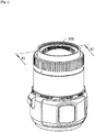
FIG. 1 is an assembled schematic diagram of a camera provided in a first preferred embodiment of the present disclosure. -
FIG. 2 is an exploded schematic view of the camera as shown inFIG. 1 . -
FIG. 3 is an exploded schematic view of the camera as shown inFIG 2 . -
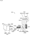
FIG. 4 is an exploded schematic view of a limiting structure as shown inFIG. 3 . -
FIG. 5 is a partially assembled schematic diagram of the limiting structure as shown inFIG. 4 assembled on said camera. -
FIG. 6 is a sectional view of the camera inFIG. 5 taken along VI-VI. -
FIG 7 is an exploded schematic view of the lens limiting assembly as shown inFIG. 3 . -
FIG. 8 is an enlarged schematic view of part VIII inFIG 4 . -
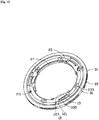
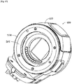
FIG. 9 is an assembled schematic diagram of the lens assembly ring as shown inFIG. 4 with a locking ring. -
FIG. 10 is an assembled schematic diagram of the lens limiting assembly as shown inFIG. 4 . -
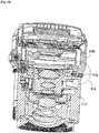
FIG. 11 is a sectional view of the camera as shown inFIG. 1 taken along XI-XI. -
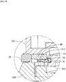
FIG. 12 is an enlarged schematic view of part XI inFIG. 11 . -
FIG. 13 is an exploded perspective view of the lens limiting assembly provided in a second preferred embodiment of the present disclosure. -
FIG. 14 is a schematic diagram of the rear side of the lens assembly ring ofFIG. 13 . -
FIG. 15 is an assembled schematic diagram of the lens assembly ring ofFIG. 14 with a locking ring. -
FIG. 16 is a partially exploded perspective schematic diagram of the camera body provided in the second preferred embodiment of the present disclosure. -
FIG. 17 is an assembly schematic diagram of the camera body provided in the second preferred embodiment of the present disclosure. -
FIG. 18 is a perspective schematic diagram of the lens of the camera provided in the second preferred embodiment of the present disclosure, before being assembled with the body. -
FIG. 19 is a sectional view of the lens ofFIG. 18 after being assembled with the body. -
FIG. 20 is an enlarged view of part XIX inFIG. 7 . -
[Table 1] Camera 300 Lens 310 Lens cone 312 Assembly part 313 Snapping body 314 Camera body 200 Fixing frame 210 Contact 215 First assembly hole 216 Second assembly hole 217 Mounting column 2171 Stepped surface 2173 Via hole 2174 Contact base mounting position 220 Locating pin 230 Bolt 240 Limiting structure 250 Press key 251 Key body 2511 First surface 2512 Second surface 2513 Snapping space 2514 Snapping part 2515 First snapping arm 2516 First inclined surface 2517 Surface 2518 Second snapping arm 2519 Limiting boss 253 Post 2531 Bracket 2533 Shaft 2535 First supporting part 2536 Second supporting part 2537 Limiting end 2538 Upper boss 2538a Lower boss 2538b Second inclined surface 2538c Support end 2539 First elastic member 255 Second elastic member 257 Lens limiting assembly 100 Elastic element 10 Elastic body 11 Elastic arm 12 First end 121 Second end 123 First locating hole 14 Snapping opening 16 Lens assembly ring 20 First end face 21 Second locating hole 211 Receiving groove 213 Second end face 23 Assembly hole 231 Bolt hole 233 Limiting part 25 Mounting part 27 Locking ring 30 Body 31 Hook 33 Connecting part 331 Bent part 333 Flange 335 Anti-slip part 35 Lens limiting assembly 500 Elastic element 510 First locating hole 514 Second locating hole 528 Fitting hole 529 Bolt hole 291 Snapping opening 516 Lens assembly ring 520 Locking ring 530 Elastic arm 512 Limiting part 522 Receiving groove 527 First fitting face 524 Smooth surface 526 Hook 532 Connecting part 5321 Bent part 5322 Second fitting face 534 Planar surface 536 Anti-slip groove 538 Camera body 600 Fixing frame 610 Contact base mounting position 612 Lens 700 Lens cone 712 Assembly part 713 Snapping body 714 Contact 720 Locating pin 721 Bolt 722 Telescopic limiting structure 650 Circular nut 651 Post 652 Camera 800 - The present disclosure will be further described by the following specific embodiments in conjunction with the above-mentioned figures.
- The technical solutions in the embodiments of the present disclosure are hereinafter described clearly and completely with reference to the accompanying drawings. Evidently, the described embodiments are only some rather than all of the embodiments of the present disclosure. All other embodiments obtained by a person of ordinary skill in the art based on the embodiments of the present disclosure without creative efforts shall fall within the scope of protection of the present disclosure.
- Referring to
FIG. 1 , the first preferred embodiment of the embodiments of the present disclosure provides acamera 300; saidcamera 300 may be an ordinary camera with a detachable lens, a single-lens reflex camera, or a camera for a special purpose, e.g., an aerial camera for an unmanned aerial vehicle. Referring toFIG. 2 , saidcamera 300 comprises alens 310, acamera body 200 and alens limiting assembly 100, and saidlens 310 is mounted in saidcamera body 200 by means of saidlens limiting assembly 100. - Said
lens 310 comprises alens cone 312, wherein anassembly part 313 is arranged at a bottom end of saidlens cone 312, and threesnapping bodies 314 spaced apart from each other are arranged on an outer wall of saidassembly part 313 and are used to cooperate with saidlens limiting assembly 100. - Referring to
FIG. 3 , saidcamera body 200 comprises afixing frame 210, and saidlens limiting assembly 100 is arranged in saidfixing frame 210.Contacts 215 are arranged in said fixingframe 210 and are electrically connected to a driver or the like in thelens 310 when thelens 310 is fastened and assembled. - Said fixing
frame 210 is provided with a plurality of contactbase mounting positions 220 for assembling saidlens 310. Said fixingframe 210 is further provided with a locatingpin 230, fourbolts 240 and a telescopiclimiting structure 250. - It is understood that the number of said locating
pins 230, saidbolts 240 and saidsnapping bodies 314 are not limited to the above numbers, and can be designed according to practical requirements. - Referring to
FIG. 4 , said limitingstructure 250 comprises apress key 251, alimiting boss 253, a firstelastic member 255 and a secondelastic member 257. Thepress key 251 is connected to the limitingboss 253, the firstelastic member 255 is arranged between thepress key 251 and the limitingboss 253, and the secondelastic member 257 is sheathed on the limitingboss 253. - The
press key 251 is movably arranged on a side surface of thecamera body 200, so as to facilitate the pressing by a user. Thepress key 251 comprises akey body 2511 and two snappingparts 2515 arranged on thekey body 2511. Thekey body 2511 is a substantially cuboid structure comprising afirst surface 2512 and asecond surface 2513 arranged oppositely. Saidfirst surface 2512 is close to said limitingboss 253, while saidsecond surface 2513 is far away from said limitingboss 253. Said two snappingparts 2515 are formed by two sides of saidfirst surface 2512 extending perpendicularly in the direction away from saidfirst surface 2512, and are arranged spaced apart from each other, and saidsecond surface 2513 is used to facilitate the pressing by a user to control thepress key 251. Each snappingpart 2515 comprises afirst snapping arm 2516 and asecond snapping arm 2519 which are integrally arranged. A firstinclined surface 2517 is formed at one side of saidfirst snapping arm 2516. In this embodiment, the firstinclined surface 2517 inclines from thefirst surface 2512 of thekey body 2511 in the direction away from thefirst surface 2512, i.e. the width of said first snappingarm 2516 in a direction parallel to thefirst surface 2512 reduces gradually from thefirst surface 2512 in the direction away from thefirst surface 2512. Thefirst snapping arm 2516 further comprises asurface 2518 opposite to the firstinclined surface 2517, and in this embodiment, thesurface 2518 is a planar surface. Thesecond snapping arm 2519 is arranged at the end of thefirst snapping arm 2516 opposite to thefirst surface 2512, and is arranged substantially parallel to thefirst surface 2512. Thesecond snapping arm 2519 comprises aclamping edge 2510, theclamping edge 2510 is formed by extending the side of the firstinclined surface 2517 opposite to thefirst surface 2512 downward in a direction parallel to thefirst surface 2512. A snappingspace 2514 is formed between the clampingedge 2510 and the firstinclined surface 2517 to snap the limitingboss 253. - It is understood that the number of said snapping
parts 2515 is not limited to the above number, and can be designed according to practical requirements. - The limiting
boss 253 can be movably arranged in thecamera body 200, and used to relatively limit thelens 310. The limitingboss 253 comprises apost 2531, abracket 2533 and ashaft 2535. Thepost 2531 and theshaft 2535 are arranged at two opposite sides of thebracket 2533. Thebracket 2533 is of a substantially inverted L-shaped structure, and comprises a first supportingpart 2536 and a second supportingpart 2537 which are arranged substantially perpendicular to each other. Thepost 2531 is vertically arranged on the first supportingpart 2536, and theshaft 2535 is vertically arranged on the other side of the first supportingpart 2536 opposite to thepost 2531 and on the same straight line as thepost 2531. The second supportingpart 2537 is arranged parallel to akey body 2511 of thepress key 251. Portions are removed by cutting inwardly from both sides of the middle lower position of said second supportingpart 2537, so as to form two limitingends 2538 at two sides of the second supportingpart 2537 and asupport end 2539 between the two limiting ends 2538. Each of said limiting ends 2538 comprises anupper boss 2538a and alower boss 2538b which are arranged to protrude relative to thesupport end 2539. Further, a secondinclined surface 2538c is formed on saidlower boss 2538b. Said secondinclined surface 2538c has an inclination matched with that of said first inclinedsurface 2517. - Referring to
FIGS. 5 and6 in conjunction, an outer wall of the fixingframe 210 is provided with afirst assembly hole 216 facing inwards. Thelens limiting assembly 100 comprises alens limiting ring 20 and thelens limiting ring 20 is provided on the fixingframe 210. Thelens assembly ring 20 is provided with asecond assembly hole 217 at the side thereof facing thelens 310. Thepress key 251 and the firstelastic member 255 pass through thefirst assembly hole 216 and are received in saidcamera body 200, and the limitingboss 253 and the secondelastic member 257 pass through saidsecond assembly hole 217 and are received in saidcamera body 200. The interior of thefirst assembly hole 216 is in communication with the interior of thesecond assembly hole 217, so that thepress key 251, the firstelastic member 255, the limitingboss 253 and the secondelastic member 257 are assembled with each other. - In this embodiment, a mounting
column 2171 is formed in the interior of thesecond assembly hole 217, steppedsurfaces 2173 are formed at two sides of the mountingcolumn 2171, and the mountingcolumn 2171 is further provided in the centre thereof with a via hole 2174 through which saidshaft 2535 can pass to prevent the limitingboss 253 from deviating. - When assembling the limiting
structure 250, thesupport end 2539 of the limitingboss 253 is accommodated between two snappingparts 2515 of thepress key 251, thefirst snapping arm 2516 of each of said snappingparts 2515 passes through each of said limiting ends 2538, the firstinclined surfaces 2517 of said first snappingarms 2516 respectively abut against the secondinclined surfaces 2538c of thelower bosses 2538b of the limitingboss 253, theclamping edge 2510 clamps to thelower boss 2538b, the firstelastic member 255 is elastically abutted between thefirst surface 2512 of thekey body 2511 and thesupport end 2539, and the secondelastic member 257 is sheathed on theshaft 2535, with one end thereof abutting against the first supportingpart 2536 and the other end abutting against the steppedsurface 2173. When a user presses thepress key 251, said second inclinedsurface 2538c and said first inclinedsurface 2517 are fitted with each other, and the acting force along the firstinclined surface 2517 can be decomposed into a pushing force perpendicular to thekey body 2511 and a downward pressure parallel to thekey body 2511. The pushing force presses the firstelastic member 255 toward thesupport end 2539, and the downward pressure acts on the secondinclined surface 2538c and drives the limitingboss 253 to move downward so as to in turn compress said secondelastic member 257 and release same from saidlens 310; and when the user no longer presses thepress key 251, the firstelastic member 255 and the secondelastic member 257 recovers from the deformation and drives thepress key 251 to rebound while driving thepost 2531 to snap into thelens 310 to prevent thelens 310 from rotating. During the rebound of thepress key 251, theclamping edge 2510 clamps to thelower boss 2538b to prevent thepress key 251 from excessively rebounding and releasing from thefirst assembly hole 216. - Said
lens limiting assembly 100 is used to lock saidlens 310 and prevent thelens 310 from rotating or falling off of saidcamera body 200 in an axial direction. - Referring to
FIG. 7 , saidlens limiting assembly 100 comprises anelastic element 10, alens assembly ring 20 and alocking ring 30. Saidlens assembly ring 20 is arranged on saidelastic element 10 and is accommodated in said lockingring 30, and said lockingring 30 can rotate relative to saidlens assembly ring 20. - Said
elastic element 10 comprises anelastic body 11 and a plurality ofelastic arms 12 on saidelastic body 11. In this embodiment, saidelastic body 11 is an annular spring piece, the number of saidelastic arms 12 is three, and said threeelastic arms 12 are arranged apart from each other at the inner side of saidelastic body 11. Specifically, each of saidelastic arms 12 is formed by extending the inner side of saidelastic body 11 downward in the direction of the axis of saidelastic body 11. Saidelastic arm 12 comprises afirst end 121 and asecond end 123, with the position of saidfirst end 121 in the direction of the axis of saidelastic body 11 being higher than the position of saidsecond end 123 in the direction of the axis of saidelastic body 11, so that agap 13 is formed between saidelastic arm 12 and saidelastic body 11 to accommodate the element of said lockingring 30. Saidelastic body 11 is further provided with afirst locating hole 14 and a snappingopening 16. In this embodiment, said snappingopening 16 is formed by recessing the outer wall of saidelastic body 11 inwardly, and the shape of said snappingopening 16 is adapted to said limitingstructure 250 of saidcamera body 200 so as to be nested and snapped in said limitingstructure 250. - Said
lens assembly ring 20 comprises afirst end face 21 and asecond end face 23 which are arranged oppositely, saidfirst end face 21 being arranged to face saidelastic element 10, and saidsecond end face 23 being arranged to face away from saidelastic element 10. Referring toFIG. 9 , saidfirst end face 21 is provided with asecond locating hole 211, and saidsecond locating hole 211 is joined in series with said first locatinghole 14 through a locatingpin 230 of saidcamera body 200. Specifically, the locatingpin 230 on saidcamera body 200 passes through said first locatinghole 14 and saidsecond locating hole 211 so as to fix saidelastic element 10 andlens assembly ring 20 on saidcamera body 200. Three receivinggrooves 213 spaced apart from each other are further recessed on saidfirst end face 21 to receive the elements on said lockingring 30. Saidsecond end face 23 is provided with anassembly hole 231 which penetrates through saidfirst end face 21 and saidsecond end face 23, and a limitingboss 253 of saidcamera body 200 passes through saidassembly hole 231 to locate saidlens 310. Saidsecond end face 23 is further provided with four bolt holes 233. Said fourbolt holes 233 are used to allow fourbolts 240 on saidcamera body 200 to pass through so as to fix saidlens assembly ring 20 to saidcamera body 200. - The inner wall of said
lens assembly ring 20 is a smooth surface, and is provided with three limitingparts 25 protruding towards the inner side and spaced apart from each other, with a mountingpart 27 being formed between every two of said limitingparts 25 so that the snappingbody 314 of saidlens 310 can pass therethrough and being mounted in saidcamera body 200. - It is understood that the number of said
elastic arms 12, said receivinggrooves 213 and said limitingparts 25 are not limited to the above numbers, and can be designed according to practical requirements. - Said locking
ring 30 comprises abody 31, ahook 33 and ananti-slip part 35, saidhook 33 and saidanti-slip part 35 being arranged at the inner and outer sides of saidbody 31.Said body 31 is of a circular ring structure, and said circular ring has a diameter larger than that of saidlens assembly ring 20 so as to receive saidlens assembly ring 20 therein. Saidhook 33 is formed by protruding inwardly from the inner side of saidbody 31, and in this embodiment, saidhook 33 is substantially L-shaped and comprises a connectingpart 331 and abent part 333 which are integrally arranged. Said connectingpart 331 is connected to the inner wall of saidbody 31, and one end of saidbent part 333 is connected to said connectingpart 331, and the other end thereof extends straightly. The end of saidbent part 333 extends toward the side close to saidelastic arm 12 to form aflange 335 which is used to abut against theelastic arm 12 of saidelastic element 10. Referring toFIG. 8 , aninclined surface 334 is formed at the side of saidflange 335 facing said connectingpart 331 to connect saidbent part 333 to saidflange 335. Referring toFIGS. 9 and10 in conjunction, when saidelastic element 10 andlens assembly ring 20 are received in said lockingring 30, the connectingpart 331 and thebent part 333 of saidhook 33 are received in said receivinggroove 213, and saidflange 335 is accommodated in saidgap 13 and abuts against saidelastic arm 12. When saidflange 335 moves relative to saidelastic arm 12 and abuts against saidelastic arm 12, saidinclined surface 334 is in contact with saidelastic arm 12, so that saidflange 335 moves across saidinclined surface 334 so as to abut against saidelastic arm 12, thereby ensuring the smooth fitting of saidflange 335 and saidelastic arm 12. Saidanti-slip part 35 may be an anti-slip thread, and is used to avoid slipping out of a hand when a user rotates said lockingring 30. - Referring to
FIG. 6 , when saidlens limiting assembly 100 is assembled in said fixingframe 210, saidelastic element 10 is nested and snapped on said limitingstructure 250 through said snappingopening 16, saidlens assembly ring 20 is accommodated on said lockingring 30 and arranged on saidelastic element 10, and said locatingpin 230 passes through the first locatinghole 14 of saidelastic element 10 and thesecond locating hole 211 of saidlens assembly ring 20 so as to connect saidelastic element 10 and saidlens assembly ring 20 in series; said limitingstructure 250 passes through theassembly hole 231 of saidlens assembly ring 20 and can stretch and retract in the direction in which said limitingstructure 250 protrudes, so as to locate saidlens 310; and said lockingring 30 is rotatably arranged on the outer side of saidlens assembly ring 20, and saidhook 33 is received in said receivinggroove 213 and abuts against theelastic arm 12 of saidelastic element 10. - Referring to
FIGS. 11 and12 , when saidlens 310 is assembled into saidlens assembly ring 20, said snappingbody 314 slides into saidlens assembly ring 20 from said mountingpart 27; then saidlens 310 is rotated so that the snappingbody 314 rotates to a position below said limitingpart 25 andelastic arm 12 of saidlens assembly ring 20; and then said lockingring 30 can be rotated in one direction, so that aflange 335 of saidhook 33 slides from saidsecond end 123 of theelastic arm 12 to saidfirst end 121 of theelastic arm 12; and since the position of saidfirst end 121 of theelastic arm 12 is higher than the position of saidsecond end 123, the sliding of saidflange 335 also presses saidelastic element 10, and saidelastic arm 12 in turn presses the snappingbody 314 of saidlens 310 so that saidlens 310 moves in the direction towards saidcamera body 200, so as to lock saidlens 310 to saidcamera body 200. When said lockingring 30 rotates in the opposite direction, saidflange 335 of thehook 33 slides from saidfirst end 121 of theelastic arm 12 to saidsecond end 123 to in turn release saidelastic arm 12, so that saidlens 310 is no longer locked to saidcamera body 200, and then saidlens 310 can be taken out from saidcamera body 200. - It is understood that the shape of said
flange 335 of thehook 33 is not limited to that shown in the above figures of the embodiments, provided that the height is greater than the distance between saidfirst end 121 of theelastic arm 12 and saidelastic body 11. - In other embodiments, said
lens assembly ring 20 is not limited to being fixed to saidcamera body 200 by means of a bolt hole and a bolt, and can also be fixed by way of adhesion. - Referring to
FIGS. 13-15 , the second preferred embodiment of the present disclosure provides alens limiting assembly 500, thelens limiting assembly 500 comprising anelastic element 510, alens assembly ring 520 and alocking ring 530. Thelens assembly ring 520 is arranged on theelastic element 510, thelens assembly ring 520 is accommodated in thelocking ring 530, and thelocking ring 530 is rotatable relative to thelens assembly ring 520. - The
elastic element 510 is an annular spring piece, and threeelastic arms 512 spaced apart from each other extend from the inner side of the spring piece. Theelastic element 510 is provided with afirst locating hole 514 and asnapping opening 516. In this embodiment, the snappingopening 516 is provided inwardly from the outer wall of theelastic element 510 and is of a semi-circular shape. - A
second locating hole 528 is provided on the end face of thelens assembly ring 520 facing theelastic element 510, and thesecond locating hole 528 is a blind hole corresponding to thefirst locating hole 514 and is connected in series therewith by means of a locating pin of the camera body. Thelens assembly ring 520 is further provided with onefitting hole 529 which penetrates through the opposite end faces and fits with other components of the camera body, and fourbolt holes 5291 fixed to the camera body; three limitingparts 522 spaced apart from each other extend from the inner wall of thelens assembly ring 520; and three receivinggrooves 527 spaced apart from each other are provided on the end face of thelens assembly ring 520 facing theelastic element 510. Each receivinggroove 527 is provided at one side with a firstfitting face 524. In this embodiment, the bottom face of the receivinggroove 527 is a planar surface, and the firstfitting face 524 is formed by extending the bottom face outwardly, and is inclined in a circumferential direction of thelens assembly ring 520. The limitingpart 522 is a rib arranged at the inner side of thelens assembly ring 520. The left and right sides of each limitingpart 522 are smooth surfaces, and may directly serve as the inner wall face of thelens assembly ring 520 or as a sliding groove face provided inwardly. - The
locking ring 530 is provided on the outer side with ananti-slip groove 538, and on the inner side with threehooks 532 spaced apart from each other. In this embodiment, eachhook 532 is of a substantially L-shape extending from the inner wall of thelocking ring 530, and eachhook 532 is provided with a connectingpart 5321 connected to the inner wall of thelocking ring 530, and abent part 5322 connected to the connectingpart 5321. A secondfitting face 534 which is inclined relative to the other parts of the surface is provided on the end of the surface of eachbent part 5322 facing saidlens assembly ring 520, and the other surface of eachbent part 5322 opposite to said secondfitting face 534 is aplanar surface 536. The secondfitting face 534 has an inclination matched with that of the firstfitting face 524, eachhook 532 is received in acorresponding receiving groove 527, the secondfitting face 534 abuts against the firstfitting face 524, and theplanar surface 536 is used to abut against theelastic arm 512 of theelastic element 510. - When a lens provided at an outer side thereof with three snapping bodies spaced apart from each other (see
FIG. 17 ) is to be assembled into thelens assembly ring 520, the snapping part slides from thesmooth surface 526 of thelens assembly ring 520 into thelens assembly ring 520; then, by rotating the lens, the snapping part may rotate to a position below the limitingpart 522 and theelastic arm 512 of theelastic element 510; and then a user may rotate thelocking ring 530 in one direction, so that the secondfitting face 534 of thehook 532 moves on the firstfitting face 524 and presses theelastic element 510 along with the increase in the height of the firstfitting face 524, and theelastic arm 512 of the elastic element will press the snapping part of the lens in the direction towards the camera body, i.e., to lock the lens. When thelocking ring 530 rotates in the opposite direction, the secondfitting face 534 of thehook 532 moves in the opposite direction on the firstfitting face 524, and theelastic element 510 is released along with the decrease in the height of the firstfitting face 524, so that the lens can rotate out. - Referring to
FIGS. 16 and17 in conjunction, thecamera body 600 provided by the embodiments of the present disclosure comprises a fixingframe 610, the fixingframe 610 having a contactbase mounting position 612 for assembling a lens which is provided at the outer side thereof with a snapping part, and thelens limiting assembly 500 being provided at the contactbase mounting position 612. The fixingframe 610 is further provided with a locatingpin 621 and fourbolts 622 protruding therefrom and is provided with a telescopic limitingstructure 650, theelastic element 510 being nested and snapped with acircular nut 651 of the telescopic limitingstructure 650 through the snappingopening 516. Thelens assembly ring 520 is fitted with thelocking ring 530 and arranged on theelastic element 510, and the locatingpin 621 passes through thefirst locating hole 514 of theelastic element 510 and passes into thesecond locating hole 528 of thelens assembly ring 520 so as to connect theelastic element 510 and thelens assembly ring 520 in series; the fourbolts 622 pass into fourbolt holes 5291 of thelens assembly ring 520 to fix thelens assembly ring 520; a post 652 of the telescopic limitingstructure 650 protrudes out of thefitting hole 529 of thelens assembly ring 520, and can stretch and retract in the direction in which the post 652 protrudes and can locate with the lens; and thelocking ring 530 is rotatably arranged at the periphery of thelens assembly ring 520. - Referring to
FIGS. 18-20 in conjunction, thecamera 800 provided by the second preferred embodiment of the present disclosure comprises a lens 700 and acamera body 600. The lens 700 comprises alens cone 712, thelens cone 712 comprises anassembly part 713, and three snappingbodies 714 spaced apart from each other are provided on the outer wall of theassembly part 713; and in this embodiment, the snappingbody 714 is a flange. When the lens 700 is to be assembled into thelens assembly ring 520, the snappingbody 714 slides from thesmooth surface 526 of thelens assembly ring 520 into thelens assembly ring 520; then, by rotating the lens 700, the snappingbody 714 rotates to a position below theelastic arm 512 of theelastic element 510; and then thelocking ring 530 can rotate in one direction, so that the secondfitting face 534 of thehook 532 moves on the firstfitting face 524 and presses theelastic element 510 along with the increase in the height of the firstfitting face 524 in the direction perpendicular to the bottom face of the receivinggroove 527, and theelastic arm 512 of theelastic element 510 will press the snappingbody 714 of the lens 700 in the direction towards saidcamera body 600, i.e., to lock the lens 700 to saidcamera body 600. When thelocking ring 530 rotates in the opposite direction, the secondfitting face 534 of thehook 532 moves in the opposite direction on the firstfitting face 524 and releases theelastic element 510 along with the decrease in the height of the firstfitting face 524, so that the lens 700 can rotate out of saidcamera body 600. -
Contacts 620 are arranged in thecamera body 600 and are electrically connected to a driver or the like in the lens 700 when the lens 700 is fastened and assembled. - It is understood that the number of said
elastic arms 512, said receivinggrooves 527, said limitingparts 522, saidhooks 532 and said snappingbodies 714 are not limited to the above numbers, and can be designed according to practical requirements. - It is understood that the shape of said
hook 532 is not necessarily as shown in the above figures of the embodiments, provided that it is able to smoothly slide between the firstfitting face 524 and theelastic element 510. - In other embodiments, said
lens assembly ring 520 is not necessarily fixed by means of a bolt hole fitted to a bolt of the camera body, and can also be fixed by adhesion and the like. - In summary, the lens limiting assembly provided in the embodiments of the present disclosure is arranged with a locking ring; when the locking ring is screwed on, the elastic element is pressed to tightly press the snapping part of the lens, so as to lock the lens to prevent the lens from rotating and falling off in an axial direction. For the camera body and camera provided in the embodiments of the present disclosure, since said limiting assembly is present, the lens and the body can be locked to prevent the lens from rotating and falling off in an axial direction.
- The description above is merely some embodiments of the present disclosure and is not intended to limit the patent scope which is defined by the claims.
Claims (15)
- A lens limiting assembly (100) for limiting a lens which is provided with a snapping body (314) on an outer side thereof, said lens limiting assembly (100) comprising:an elastic element (10); anda lens assembly ring (20) which is arranged on said elastic element (10),wherein said snapping body (314) is snapped below the elastic element (10) when said lens is assembled into said lens assembly ring (20);characterized in that said lens limiting assembly (100) further comprises:
a locking ring (30) which is rotatably arranged outside the lens assembly ring (20), wherein the locking ring (30) abuts against and presses said elastic element (10) when said locking ring (30) rotates in one direction, so that said elastic element (10) presses the snapping body (314) of said lens so as to lock the lens. - The lens limiting assembly (100) as claimed in claim 1, wherein said elastic element (10) is an annular spring piece, said elastic element (10) comprises an elastic body and an elastic arm, said elastic arm is formed by extending an inner side of said elastic body downward along an axis of said elastic body, and said locking ring (30) comprises a flange which abuts against said elastic arm.
- The lens limiting assembly (100) as claimed in claim 2, wherein said elastic arm comprises a first end and a second end, a position of said first end in the direction of the axis of said elastic body is higher than a position of said second end in the direction of the axis of said elastic body so that a gap is formed between said elastic arm and said elastic body, and said flange is accommodated in said gap.
- The lens limiting assembly (100) as claimed in claim 2, wherein said locking ring (30) comprises a body and a hook which protrudes from said body inwardly, said hook comprises a connecting part and a bent part, said connecting part is connected to an inner wall of said body, said lens assembly ring (20) comprises an accommodating groove, said connecting part and said bent part are accommodated in said accommodating groove, one end of said bent part is connected to said connecting part, the other end thereof extends straightly, and said flange is formed at a tail end of said bent part and extends toward said elastic arm,
wherein further preferably:
a side of said flange facing said connecting part forms an inclined surface which connects said flange and said bent part. - The lens limiting assembly (100) as claimed in claim 1, wherein said lens assembly ring (20) comprises a first fitting face, and said first fitting face is arranged on an end face of said lens assembly ring (20) facing said elastic element (10) and is inclined in a circumferential direction of said lens assembly ring (20).
- The lens limiting assembly (100) as claimed in claim 5, wherein the end face of said lens assembly ring (20) is further provided with a receiving groove connected to said first fitting face, said lens assembly ring (20) is accommodated in said locking ring (30), said locking ring (30) comprises a hook, said hook extends from the inner side of said locking ring (30) and is received in said receiving groove, said lens assembly ring (20) comprises a second fitting face which abuts against said first fitting face, said second fitting face is arranged at an end of a surface of said hook facing said lens assembly ring (20), the other surface of said hook opposite to said second fitting face is a planar surface, and said planar surface abuts against said elastic element (10), wherein further preferably:
said hook comprises a connecting part connected to an inner side of said locking ring (30) and a bent part bending and extending from said connecting part, said second fitting face is arranged at the end of the surface of said bent part facing said lens assembly ring (20), and said planar surface is arranged on the other surface of said bent part opposite to said second fitting face. - The lens limiting assembly (100) as claimed in claim 1, wherein said lens assembly ring (20) comprises a limiting part, the left and right sides of said limiting part are smooth surfaces, so that said lens is adapted to rotate after said lens slides from said smooth surface into said lens assembly ring (20), in order to move said snapping body (314) to a position below said limiting part and said elastic element (10).
- A camera body comprising a fixing frame and a lens limiting assembly (100) according to one of the preceding claims, said fixing frame having a contact base mounting position, said lens limiting assembly (100) being arranged at said contact base mounting position, said lens limiting assembly (100) being used to limit a lens, and said lens being provided with a snapping body (314) on the outer side thereof.
- The camera body as claimed in claim 8, wherein said lens assembly ring (20) comprises a plurality of limiting parts spaced apart from one another, a mounting part is formed between two adjacent limiting parts, and said snapping body (314) enters said lens assembly ring (20) via said mounting part and is snapped below said limiting part.
- The camera body as claimed in claim 8, wherein said fixing frame is provided with a locating pin and a plurality of bolts, said elastic element (10) is provided with a first locating hole, said lens assembly ring (20) comprises a first end face and a second end face which are arranged oppositely, said first end face is provided with a second locating hole, said locating pin passes through said first locating hole and said second locating hole, said second end face is provided with a plurality of bolt holes, and said bolts correspondingly pass through said bolt holes,
wherein further preferably:
said fixing frame further comprises a limiting structure, said elastic element (10) is provided with a snapping opening, said limiting structure is nested and snapped with said snapping opening, said lens assembly ring (20) is further provided with an assembly hole penetrating through said first end face and said second end face, and said limiting structure comprises a limiting boss which passes through said assembly hole to locate said lens. - The camera body as claimed in claim 8, wherein a first assembly hole is provided inwardly on a outer wall of the fixing frame, a second assembly hole is provided on a side of the lens assembly ring (20) facing the lens, the first assembly hole and the second assembly hole are in communication with each other, the limiting structure further comprises a press key, a first elastic member and a second elastic member, the press key and the first elastic member pass through the first assembly hole, and the limiting boss and the second elastic member pass through the second assembly hole.
- The camera body as claimed in claim 11, wherein the press key comprises a key body and two snapping parts spaced apart from each other and protruding from the key body, each of said snapping parts comprises a first connecting arm and a second connecting arm which are connected to each other, the first connecting arm comprises a first inclined surface, the second connecting arm comprises a clamping edge, the clamping edge is formed by extending the first inclined surface downward in a direction parallel to the key body, the first inclined surface abuts against the limiting structure, and the clamping edge clamps the limiting structure.
- The camera body as claimed in claim 11, wherein the limiting structure comprises a bracket, a post and a shaft, the bracket comprises a first supporting part, the post and the shaft are arranged at two opposite sides of the first supporting part, a mounting column is formed in the second assembly hole, stepped surfaces are formed at two sides of the mounting column, the second elastic member is sheathed on the shaft and abuts between the first supporting part and the stepped surface, and the mounting column is provided with a via hole through which the shaft passes,
wherein further preferably:
the bracket comprises a second supporting part, the upper part of the second supporting part inwardly forms two limiting ends and a support end, the first elastic member abuts between the key body and the support end, said limiting end comprises an upper boss and a lower boss which are arranged oppositely, said lower boss forms a second inclined surface, said first inclined surface abuts against the second inclined surface, said snapping part passes through said limiting end, and said clamping edge clamps said lower boss. - A camera comprising a lens and a camera body according to one of the claims 8 to 13.
- The camera as claimed in claim 14, wherein said lens comprises a lens cone, the bottom end of said lens cone is provided with an assembly part, and said snapping bodies are arranged apart from each other on the outer wall of said assembly part.
Priority Applications (1)
| Application Number | Priority Date | Filing Date | Title |
|---|---|---|---|
| EP20158592.4A EP3677965A1 (en) | 2014-10-27 | 2015-05-21 | Lens limiting assembly, camera body, and camera |
Applications Claiming Priority (2)
| Application Number | Priority Date | Filing Date | Title |
|---|---|---|---|
| PCT/CN2014/089604 WO2016065518A1 (en) | 2014-10-27 | 2014-10-27 | Lens limiting assembly, camera body, and camera module |
| PCT/CN2015/079521 WO2016065893A1 (en) | 2014-10-27 | 2015-05-21 | Lens limiting assembly, camera body, and camera |
Related Child Applications (2)
| Application Number | Title | Priority Date | Filing Date |
|---|---|---|---|
| EP20158592.4A Division EP3677965A1 (en) | 2014-10-27 | 2015-05-21 | Lens limiting assembly, camera body, and camera |
| EP20158592.4A Division-Into EP3677965A1 (en) | 2014-10-27 | 2015-05-21 | Lens limiting assembly, camera body, and camera |
Publications (3)
| Publication Number | Publication Date |
|---|---|
| EP3214493A1 EP3214493A1 (en) | 2017-09-06 |
| EP3214493A4 EP3214493A4 (en) | 2017-09-06 |
| EP3214493B1 true EP3214493B1 (en) | 2020-04-01 |
Family
ID=55724994
Family Applications (2)
| Application Number | Title | Priority Date | Filing Date |
|---|---|---|---|
| EP15853756.3A Active EP3214493B1 (en) | 2014-10-27 | 2015-05-21 | Lens limiting assembly, camera body, and camera |
| EP20158592.4A Withdrawn EP3677965A1 (en) | 2014-10-27 | 2015-05-21 | Lens limiting assembly, camera body, and camera |
Family Applications After (1)
| Application Number | Title | Priority Date | Filing Date |
|---|---|---|---|
| EP20158592.4A Withdrawn EP3677965A1 (en) | 2014-10-27 | 2015-05-21 | Lens limiting assembly, camera body, and camera |
Country Status (5)
| Country | Link |
|---|---|
| US (4) | US10073325B2 (en) |
| EP (2) | EP3214493B1 (en) |
| JP (1) | JP6208896B2 (en) |
| CN (1) | CN105518525B (en) |
| WO (2) | WO2016065518A1 (en) |
Families Citing this family (23)
| Publication number | Priority date | Publication date | Assignee | Title |
|---|---|---|---|---|
| WO2016061773A1 (en) * | 2014-10-22 | 2016-04-28 | 深圳市大疆创新科技有限公司 | Telescopic limiting structure, camera body, and camera |
| WO2016065518A1 (en) * | 2014-10-27 | 2016-05-06 | 深圳市大疆创新科技有限公司 | Lens limiting assembly, camera body, and camera module |
| CN107404603B (en) * | 2016-05-19 | 2021-05-04 | 环球兴国际有限公司 | Lens adapter and back locking type lens fixing device thereof |
| JP6758974B2 (en) * | 2016-07-20 | 2020-09-23 | キヤノン株式会社 | Electronic devices and monitoring systems |
| USD856396S1 (en) * | 2016-08-31 | 2019-08-13 | Fujifilm Corporation | Lens for camera |
| CN111741202B (en) * | 2017-10-11 | 2021-12-24 | 深圳市大疆灵眸科技有限公司 | Image forming apparatus with a plurality of image forming units |
| JP6521023B2 (en) * | 2017-10-26 | 2019-05-29 | 株式会社ニコン | accessory |
| USD896872S1 (en) * | 2018-01-22 | 2020-09-22 | Samyang Optics Co., Ltd | Interchangeable lens for camera |
| USD888804S1 (en) * | 2018-05-04 | 2020-06-30 | New Ideas Manufacturing LLC | Step-up ring |
| USD908162S1 (en) * | 2018-08-24 | 2021-01-19 | Samyang Optics Co., Ltd. | Interchangeable lens for camera |
| JP6521163B1 (en) * | 2018-10-18 | 2019-05-29 | 株式会社ニコン | interchangeable lens |
| JP6794599B2 (en) * | 2019-02-25 | 2020-12-02 | エスゼット ディージェイアイ テクノロジー カンパニー リミテッドSz Dji Technology Co.,Ltd | Mounts, imaging devices, imaging systems, and moving objects |
| TWI756523B (en) * | 2019-03-12 | 2022-03-01 | 緯創資通股份有限公司 | Lock mechanism and holding structure for electronic device |
| CN110035212B (en) * | 2019-05-21 | 2023-11-03 | 昆山丘钛微电子科技有限公司 | Camera module and terminal |
| CN110240224A (en) * | 2019-07-15 | 2019-09-17 | 珠海格力电器股份有限公司 | The mounting structure and light emitting device of illuminating part |
| JP2021032951A (en) * | 2019-08-20 | 2021-03-01 | キヤノン株式会社 | Device body of imaging device, mount device, and flange back adjustment member |
| CN112511721B (en) * | 2019-08-26 | 2022-07-08 | 杭州海康威视数字技术股份有限公司 | Video camera |
| CN112543263B (en) * | 2019-09-20 | 2023-06-16 | 富泰华工业(深圳)有限公司 | Camera and electronic device |
| JP6953663B1 (en) * | 2020-08-03 | 2021-10-27 | エスゼット ディージェイアイ テクノロジー カンパニー リミテッドSz Dji Technology Co.,Ltd | Mount structure and imaging device |
| JP6957808B1 (en) * | 2020-08-03 | 2021-11-02 | エスゼット ディージェイアイ テクノロジー カンパニー リミテッドSz Dji Technology Co.,Ltd | Mount structure and imaging device |
| CN112212143A (en) * | 2020-09-25 | 2021-01-12 | 杭州未来已来科技有限公司 | Intelligent household safety anti-theft device |
| CN115002321B (en) * | 2022-05-27 | 2024-04-23 | 杭州海康威视数字技术股份有限公司 | Video camera |
| CN115202028B (en) * | 2022-07-08 | 2024-04-12 | 嘉兴锐星光学仪器有限公司 | Astronomical star shooting mirror with built-in star guiding function and replaceable lens |
Family Cites Families (27)
| Publication number | Priority date | Publication date | Assignee | Title |
|---|---|---|---|---|
| US73325A (en) * | 1868-01-14 | John w | ||
| US3559542A (en) * | 1969-02-03 | 1971-02-02 | Camera Service Center Inc | Quick release and locking mechanism for a camera lens mounting |
| US3782260A (en) * | 1972-07-14 | 1974-01-01 | Eastman Kodak Co | Photographic camera with interchangeable lenses and bayonet lock |
| JPS5836726U (en) * | 1981-03-25 | 1983-03-10 | ソニー株式会社 | lens device |
| JPH0623821B2 (en) * | 1983-09-02 | 1994-03-30 | ミノルタカメラ株式会社 | Bayonet mount device and optical equipment using this device |
| JP2512749B2 (en) | 1987-05-22 | 1996-07-03 | 株式会社 タムロン | Lens mount mechanism |
| JP2942294B2 (en) * | 1990-02-14 | 1999-08-30 | 旭光学工業株式会社 | Optical device mounting members |
| BE1013550A3 (en) | 2000-06-09 | 2002-03-05 | Barco Nv | Objective confirmation. |
| DE10121439A1 (en) * | 2001-04-27 | 2002-10-31 | Hensoldt & Soehne Optik | detent mechanism |
| JP4152168B2 (en) | 2002-08-12 | 2008-09-17 | Thk株式会社 | Lens mounting mechanism and projector device |
| JP4555556B2 (en) * | 2003-10-09 | 2010-10-06 | オリンパス株式会社 | Interchangeable lens camera system |
| JP4986501B2 (en) * | 2006-04-28 | 2012-07-25 | 富士フイルム株式会社 | Optical option mounting ring |
| JP4963914B2 (en) * | 2006-09-25 | 2012-06-27 | ペンタックスリコーイメージング株式会社 | Interchangeable lens barrel and interchangeable lens barrel camera system |
| CN201104277Y (en) * | 2007-11-07 | 2008-08-20 | 承奕科技股份有限公司 | Attachment lens fixing structure of camera |
| JP5086214B2 (en) * | 2008-09-19 | 2012-11-28 | 株式会社日立製作所 | Lens mounting mechanism and projector apparatus having lens mounting mechanism |
| JP5810661B2 (en) * | 2011-06-17 | 2015-11-11 | リコーイメージング株式会社 | Camera body |
| JP2013092556A (en) * | 2011-10-24 | 2013-05-16 | Sony Corp | Accessory and imaging apparatus |
| US8830607B2 (en) * | 2012-04-10 | 2014-09-09 | Canon Kabushiki Kaisha | Image pickup apparatus capable of interchanging lenses and lens mount therefor |
| JP2013235074A (en) * | 2012-05-07 | 2013-11-21 | Olympus Imaging Corp | Optical instrument |
| CN103581508A (en) | 2012-07-18 | 2014-02-12 | 派尔高公司 | Video camera |
| JP2014157248A (en) * | 2013-02-15 | 2014-08-28 | Nikon Corp | Camera accessory |
| JP2015141382A (en) * | 2014-01-30 | 2015-08-03 | ソニー株式会社 | Imaging apparatus and imaging system |
| US9568808B2 (en) * | 2014-08-07 | 2017-02-14 | Houdinix Llc | Low-profile lens mount |
| WO2016061773A1 (en) * | 2014-10-22 | 2016-04-28 | 深圳市大疆创新科技有限公司 | Telescopic limiting structure, camera body, and camera |
| WO2016065518A1 (en) * | 2014-10-27 | 2016-05-06 | 深圳市大疆创新科技有限公司 | Lens limiting assembly, camera body, and camera module |
| CN204178095U (en) * | 2014-10-27 | 2015-02-25 | 深圳市大疆创新科技有限公司 | The fuselage of camera lens limit assembly, camera and camera model |
| TWI660660B (en) * | 2015-02-11 | 2019-05-21 | 佳能企業股份有限公司 | Connecting module and system using the same |
-
2014
- 2014-10-27 WO PCT/CN2014/089604 patent/WO2016065518A1/en active Application Filing
- 2014-10-27 CN CN201480019859.5A patent/CN105518525B/en active Active
-
2015
- 2015-05-21 JP JP2016560425A patent/JP6208896B2/en not_active Expired - Fee Related
- 2015-05-21 EP EP15853756.3A patent/EP3214493B1/en active Active
- 2015-05-21 EP EP20158592.4A patent/EP3677965A1/en not_active Withdrawn
- 2015-05-21 WO PCT/CN2015/079521 patent/WO2016065893A1/en active Application Filing
-
2017
- 2017-04-26 US US15/497,368 patent/US10073325B2/en active Active
-
2018
- 2018-09-04 US US16/121,117 patent/US10437135B2/en not_active Expired - Fee Related
-
2019
- 2019-09-18 US US16/575,055 patent/US10859893B2/en active Active
-
2020
- 2020-12-07 US US17/114,397 patent/US11347136B2/en active Active
Non-Patent Citations (1)
| Title |
|---|
| None * |
Also Published As
| Publication number | Publication date |
|---|---|
| CN105518525B (en) | 2018-02-02 |
| JP6208896B2 (en) | 2017-10-04 |
| US10073325B2 (en) | 2018-09-11 |
| EP3214493A1 (en) | 2017-09-06 |
| US20170227833A1 (en) | 2017-08-10 |
| EP3214493A4 (en) | 2017-09-06 |
| US20180373124A1 (en) | 2018-12-27 |
| US10859893B2 (en) | 2020-12-08 |
| US20210088883A1 (en) | 2021-03-25 |
| WO2016065518A1 (en) | 2016-05-06 |
| WO2016065893A1 (en) | 2016-05-06 |
| EP3677965A1 (en) | 2020-07-08 |
| US11347136B2 (en) | 2022-05-31 |
| JP2017509930A (en) | 2017-04-06 |
| US20200012176A1 (en) | 2020-01-09 |
| US10437135B2 (en) | 2019-10-08 |
| CN105518525A (en) | 2016-04-20 |
Similar Documents
| Publication | Publication Date | Title |
|---|---|---|
| EP3214493B1 (en) | Lens limiting assembly, camera body, and camera | |
| US7866615B2 (en) | Display support device | |
| US10732489B2 (en) | Telescopic limiting structure, camera body and camera | |
| US8620153B2 (en) | Snap-on camera filter mount | |
| US20150212395A1 (en) | Imaging apparatus and imaging system | |
| CN204807892U (en) | Fuselage and camera of spacing subassembly of camera lens, camera | |
| CN105518527B (en) | Lens limiting assembly, camera body and camera | |
| EP3101472B1 (en) | Camera and adapter | |
| US9525810B2 (en) | Camera apparatus and mount adapter | |
| CN110839125B (en) | Electronic device and use method thereof | |
| CN217022918U (en) | Cloud platform coupling assembling and unmanned aerial vehicle | |
| US6130788A (en) | Structure for holding lens | |
| JP2011221300A (en) | Lens device and optical accessory | |
| JP2010266545A (en) | Imaging apparatus | |
| CN112650006A (en) | Lens limiting assembly, camera body and camera | |
| JP6492686B2 (en) | Accessories for photographic equipment | |
| CN110824815B (en) | Accessory and image forming apparatus including the same | |
| US8926200B2 (en) | Imaging device | |
| JP6113804B2 (en) | Mirror device for vehicle | |
| JP6485000B2 (en) | Camera accessories | |
| JP2021148869A (en) | Fixing device and imaging apparatus | |
| JP2019124762A (en) | interchangeable lens | |
| JP2021019456A (en) | Bracket and holding structure of electric connection box | |
| JP2017058412A (en) | Tripod shoe, lens barrel and attachment/detachment structure of lens barrel and tripod shoe |
Legal Events
| Date | Code | Title | Description |
|---|---|---|---|
| STAA | Information on the status of an ep patent application or granted ep patent |
Free format text: STATUS: THE INTERNATIONAL PUBLICATION HAS BEEN MADE |
|
| PUAI | Public reference made under article 153(3) epc to a published international application that has entered the european phase |
Free format text: ORIGINAL CODE: 0009012 |
|
| STAA | Information on the status of an ep patent application or granted ep patent |
Free format text: STATUS: REQUEST FOR EXAMINATION WAS MADE |
|
| 17P | Request for examination filed |
Effective date: 20170515 |
|
| A4 | Supplementary search report drawn up and despatched |
Effective date: 20170731 |
|
| AK | Designated contracting states |
Kind code of ref document: A1 Designated state(s): AL AT BE BG CH CY CZ DE DK EE ES FI FR GB GR HR HU IE IS IT LI LT LU LV MC MK MT NL NO PL PT RO RS SE SI SK SM TR |
|
| AX | Request for extension of the european patent |
Extension state: BA ME |
|
| DAV | Request for validation of the european patent (deleted) | ||
| DAX | Request for extension of the european patent (deleted) | ||
| STAA | Information on the status of an ep patent application or granted ep patent |
Free format text: STATUS: EXAMINATION IS IN PROGRESS |
|
| 17Q | First examination report despatched |
Effective date: 20180503 |
|
| GRAP | Despatch of communication of intention to grant a patent |
Free format text: ORIGINAL CODE: EPIDOSNIGR1 |
|
| STAA | Information on the status of an ep patent application or granted ep patent |
Free format text: STATUS: GRANT OF PATENT IS INTENDED |
|
| INTG | Intention to grant announced |
Effective date: 20191021 |
|
| GRAS | Grant fee paid |
Free format text: ORIGINAL CODE: EPIDOSNIGR3 |
|
| GRAA | (expected) grant |
Free format text: ORIGINAL CODE: 0009210 |
|
| STAA | Information on the status of an ep patent application or granted ep patent |
Free format text: STATUS: THE PATENT HAS BEEN GRANTED |
|
| AK | Designated contracting states |
Kind code of ref document: B1 Designated state(s): AL AT BE BG CH CY CZ DE DK EE ES FI FR GB GR HR HU IE IS IT LI LT LU LV MC MK MT NL NO PL PT RO RS SE SI SK SM TR |
|
| REG | Reference to a national code |
Ref country code: GB Ref legal event code: FG4D |
|
| REG | Reference to a national code |
Ref country code: CH Ref legal event code: EP Ref country code: AT Ref legal event code: REF Ref document number: 1252142 Country of ref document: AT Kind code of ref document: T Effective date: 20200415 |
|
| REG | Reference to a national code |
Ref country code: DE Ref legal event code: R096 Ref document number: 602015050029 Country of ref document: DE |
|
| REG | Reference to a national code |
Ref country code: IE Ref legal event code: FG4D |
|
| REG | Reference to a national code |
Ref country code: SE Ref legal event code: TRGR |
|
| REG | Reference to a national code |
Ref country code: NL Ref legal event code: FP |
|
| PG25 | Lapsed in a contracting state [announced via postgrant information from national office to epo] |
Ref country code: BG Free format text: LAPSE BECAUSE OF FAILURE TO SUBMIT A TRANSLATION OF THE DESCRIPTION OR TO PAY THE FEE WITHIN THE PRESCRIBED TIME-LIMIT Effective date: 20200701 |
|
| REG | Reference to a national code |
Ref country code: LT Ref legal event code: MG4D |
|
| PG25 | Lapsed in a contracting state [announced via postgrant information from national office to epo] |
Ref country code: FI Free format text: LAPSE BECAUSE OF FAILURE TO SUBMIT A TRANSLATION OF THE DESCRIPTION OR TO PAY THE FEE WITHIN THE PRESCRIBED TIME-LIMIT Effective date: 20200401 Ref country code: PT Free format text: LAPSE BECAUSE OF FAILURE TO SUBMIT A TRANSLATION OF THE DESCRIPTION OR TO PAY THE FEE WITHIN THE PRESCRIBED TIME-LIMIT Effective date: 20200817 Ref country code: GR Free format text: LAPSE BECAUSE OF FAILURE TO SUBMIT A TRANSLATION OF THE DESCRIPTION OR TO PAY THE FEE WITHIN THE PRESCRIBED TIME-LIMIT Effective date: 20200702 Ref country code: NO Free format text: LAPSE BECAUSE OF FAILURE TO SUBMIT A TRANSLATION OF THE DESCRIPTION OR TO PAY THE FEE WITHIN THE PRESCRIBED TIME-LIMIT Effective date: 20200701 Ref country code: IS Free format text: LAPSE BECAUSE OF FAILURE TO SUBMIT A TRANSLATION OF THE DESCRIPTION OR TO PAY THE FEE WITHIN THE PRESCRIBED TIME-LIMIT Effective date: 20200801 Ref country code: CZ Free format text: LAPSE BECAUSE OF FAILURE TO SUBMIT A TRANSLATION OF THE DESCRIPTION OR TO PAY THE FEE WITHIN THE PRESCRIBED TIME-LIMIT Effective date: 20200401 Ref country code: LT Free format text: LAPSE BECAUSE OF FAILURE TO SUBMIT A TRANSLATION OF THE DESCRIPTION OR TO PAY THE FEE WITHIN THE PRESCRIBED TIME-LIMIT Effective date: 20200401 |
|
| REG | Reference to a national code |
Ref country code: AT Ref legal event code: MK05 Ref document number: 1252142 Country of ref document: AT Kind code of ref document: T Effective date: 20200401 |
|
| PG25 | Lapsed in a contracting state [announced via postgrant information from national office to epo] |
Ref country code: HR Free format text: LAPSE BECAUSE OF FAILURE TO SUBMIT A TRANSLATION OF THE DESCRIPTION OR TO PAY THE FEE WITHIN THE PRESCRIBED TIME-LIMIT Effective date: 20200401 Ref country code: LV Free format text: LAPSE BECAUSE OF FAILURE TO SUBMIT A TRANSLATION OF THE DESCRIPTION OR TO PAY THE FEE WITHIN THE PRESCRIBED TIME-LIMIT Effective date: 20200401 Ref country code: RS Free format text: LAPSE BECAUSE OF FAILURE TO SUBMIT A TRANSLATION OF THE DESCRIPTION OR TO PAY THE FEE WITHIN THE PRESCRIBED TIME-LIMIT Effective date: 20200401 |
|
| PG25 | Lapsed in a contracting state [announced via postgrant information from national office to epo] |
Ref country code: AL Free format text: LAPSE BECAUSE OF FAILURE TO SUBMIT A TRANSLATION OF THE DESCRIPTION OR TO PAY THE FEE WITHIN THE PRESCRIBED TIME-LIMIT Effective date: 20200401 |
|
| REG | Reference to a national code |
Ref country code: DE Ref legal event code: R097 Ref document number: 602015050029 Country of ref document: DE |
|
| PG25 | Lapsed in a contracting state [announced via postgrant information from national office to epo] |
Ref country code: LI Free format text: LAPSE BECAUSE OF NON-PAYMENT OF DUE FEES Effective date: 20200531 Ref country code: ES Free format text: LAPSE BECAUSE OF FAILURE TO SUBMIT A TRANSLATION OF THE DESCRIPTION OR TO PAY THE FEE WITHIN THE PRESCRIBED TIME-LIMIT Effective date: 20200401 Ref country code: MC Free format text: LAPSE BECAUSE OF FAILURE TO SUBMIT A TRANSLATION OF THE DESCRIPTION OR TO PAY THE FEE WITHIN THE PRESCRIBED TIME-LIMIT Effective date: 20200401 Ref country code: RO Free format text: LAPSE BECAUSE OF FAILURE TO SUBMIT A TRANSLATION OF THE DESCRIPTION OR TO PAY THE FEE WITHIN THE PRESCRIBED TIME-LIMIT Effective date: 20200401 Ref country code: AT Free format text: LAPSE BECAUSE OF FAILURE TO SUBMIT A TRANSLATION OF THE DESCRIPTION OR TO PAY THE FEE WITHIN THE PRESCRIBED TIME-LIMIT Effective date: 20200401 Ref country code: DK Free format text: LAPSE BECAUSE OF FAILURE TO SUBMIT A TRANSLATION OF THE DESCRIPTION OR TO PAY THE FEE WITHIN THE PRESCRIBED TIME-LIMIT Effective date: 20200401 Ref country code: CH Free format text: LAPSE BECAUSE OF NON-PAYMENT OF DUE FEES Effective date: 20200531 Ref country code: EE Free format text: LAPSE BECAUSE OF FAILURE TO SUBMIT A TRANSLATION OF THE DESCRIPTION OR TO PAY THE FEE WITHIN THE PRESCRIBED TIME-LIMIT Effective date: 20200401 Ref country code: SM Free format text: LAPSE BECAUSE OF FAILURE TO SUBMIT A TRANSLATION OF THE DESCRIPTION OR TO PAY THE FEE WITHIN THE PRESCRIBED TIME-LIMIT Effective date: 20200401 Ref country code: IT Free format text: LAPSE BECAUSE OF FAILURE TO SUBMIT A TRANSLATION OF THE DESCRIPTION OR TO PAY THE FEE WITHIN THE PRESCRIBED TIME-LIMIT Effective date: 20200401 |
|
| PLBE | No opposition filed within time limit |
Free format text: ORIGINAL CODE: 0009261 |
|
| STAA | Information on the status of an ep patent application or granted ep patent |
Free format text: STATUS: NO OPPOSITION FILED WITHIN TIME LIMIT |
|
| PG25 | Lapsed in a contracting state [announced via postgrant information from national office to epo] |
Ref country code: PL Free format text: LAPSE BECAUSE OF FAILURE TO SUBMIT A TRANSLATION OF THE DESCRIPTION OR TO PAY THE FEE WITHIN THE PRESCRIBED TIME-LIMIT Effective date: 20200401 Ref country code: SK Free format text: LAPSE BECAUSE OF FAILURE TO SUBMIT A TRANSLATION OF THE DESCRIPTION OR TO PAY THE FEE WITHIN THE PRESCRIBED TIME-LIMIT Effective date: 20200401 |
|
| 26N | No opposition filed |
Effective date: 20210112 |
|
| REG | Reference to a national code |
Ref country code: BE Ref legal event code: MM Effective date: 20200531 |
|
| PG25 | Lapsed in a contracting state [announced via postgrant information from national office to epo] |
Ref country code: LU Free format text: LAPSE BECAUSE OF NON-PAYMENT OF DUE FEES Effective date: 20200521 |
|
| PG25 | Lapsed in a contracting state [announced via postgrant information from national office to epo] |
Ref country code: IE Free format text: LAPSE BECAUSE OF NON-PAYMENT OF DUE FEES Effective date: 20200521 |
|
| PG25 | Lapsed in a contracting state [announced via postgrant information from national office to epo] |
Ref country code: BE Free format text: LAPSE BECAUSE OF NON-PAYMENT OF DUE FEES Effective date: 20200531 Ref country code: SI Free format text: LAPSE BECAUSE OF FAILURE TO SUBMIT A TRANSLATION OF THE DESCRIPTION OR TO PAY THE FEE WITHIN THE PRESCRIBED TIME-LIMIT Effective date: 20200401 |
|
| PGFP | Annual fee paid to national office [announced via postgrant information from national office to epo] |
Ref country code: DE Payment date: 20210520 Year of fee payment: 7 Ref country code: FR Payment date: 20210520 Year of fee payment: 7 Ref country code: NL Payment date: 20210519 Year of fee payment: 7 |
|
| PGFP | Annual fee paid to national office [announced via postgrant information from national office to epo] |
Ref country code: GB Payment date: 20210525 Year of fee payment: 7 Ref country code: SE Payment date: 20210519 Year of fee payment: 7 |
|
| PG25 | Lapsed in a contracting state [announced via postgrant information from national office to epo] |
Ref country code: TR Free format text: LAPSE BECAUSE OF FAILURE TO SUBMIT A TRANSLATION OF THE DESCRIPTION OR TO PAY THE FEE WITHIN THE PRESCRIBED TIME-LIMIT Effective date: 20200401 Ref country code: MT Free format text: LAPSE BECAUSE OF FAILURE TO SUBMIT A TRANSLATION OF THE DESCRIPTION OR TO PAY THE FEE WITHIN THE PRESCRIBED TIME-LIMIT Effective date: 20200401 Ref country code: CY Free format text: LAPSE BECAUSE OF FAILURE TO SUBMIT A TRANSLATION OF THE DESCRIPTION OR TO PAY THE FEE WITHIN THE PRESCRIBED TIME-LIMIT Effective date: 20200401 |
|
| PG25 | Lapsed in a contracting state [announced via postgrant information from national office to epo] |
Ref country code: MK Free format text: LAPSE BECAUSE OF FAILURE TO SUBMIT A TRANSLATION OF THE DESCRIPTION OR TO PAY THE FEE WITHIN THE PRESCRIBED TIME-LIMIT Effective date: 20200401 |
|
| REG | Reference to a national code |
Ref country code: DE Ref legal event code: R119 Ref document number: 602015050029 Country of ref document: DE |
|
| REG | Reference to a national code |
Ref country code: SE Ref legal event code: EUG |
|
| REG | Reference to a national code |
Ref country code: NL Ref legal event code: MM Effective date: 20220601 |
|
| GBPC | Gb: european patent ceased through non-payment of renewal fee |
Effective date: 20220521 |
|
| PG25 | Lapsed in a contracting state [announced via postgrant information from national office to epo] |
Ref country code: SE Free format text: LAPSE BECAUSE OF NON-PAYMENT OF DUE FEES Effective date: 20220522 |
|
| PG25 | Lapsed in a contracting state [announced via postgrant information from national office to epo] |
Ref country code: FR Free format text: LAPSE BECAUSE OF NON-PAYMENT OF DUE FEES Effective date: 20220531 |
|
| PG25 | Lapsed in a contracting state [announced via postgrant information from national office to epo] |
Ref country code: GB Free format text: LAPSE BECAUSE OF NON-PAYMENT OF DUE FEES Effective date: 20220521 Ref country code: DE Free format text: LAPSE BECAUSE OF NON-PAYMENT OF DUE FEES Effective date: 20221201 |
|
| PG25 | Lapsed in a contracting state [announced via postgrant information from national office to epo] |
Ref country code: NL Free format text: LAPSE BECAUSE OF NON-PAYMENT OF DUE FEES Effective date: 20220601 |