EP3214413A2 - Device and method for applying a solid measure - Google Patents
Device and method for applying a solid measure Download PDFInfo
- Publication number
- EP3214413A2 EP3214413A2 EP16201603.4A EP16201603A EP3214413A2 EP 3214413 A2 EP3214413 A2 EP 3214413A2 EP 16201603 A EP16201603 A EP 16201603A EP 3214413 A2 EP3214413 A2 EP 3214413A2
- Authority
- EP
- European Patent Office
- Prior art keywords
- punch
- material measure
- base body
- axis
- along
- Prior art date
- Legal status (The legal status is an assumption and is not a legal conclusion. Google has not performed a legal analysis and makes no representation as to the accuracy of the status listed.)
- Granted
Links
- 238000000034 method Methods 0.000 title claims abstract description 11
- 239000007787 solid Substances 0.000 title 1
- 239000000463 material Substances 0.000 claims abstract description 63
- 238000006073 displacement reaction Methods 0.000 claims description 8
- 239000002313 adhesive film Substances 0.000 claims description 7
- 230000006835 compression Effects 0.000 claims description 5
- 238000007906 compression Methods 0.000 claims description 5
- 238000004026 adhesive bonding Methods 0.000 abstract description 3
- 229910000831 Steel Inorganic materials 0.000 description 2
- 238000010276 construction Methods 0.000 description 2
- 230000001419 dependent effect Effects 0.000 description 2
- 238000005259 measurement Methods 0.000 description 2
- 239000010959 steel Substances 0.000 description 2
- 239000000853 adhesive Substances 0.000 description 1
- 230000001070 adhesive effect Effects 0.000 description 1
- 230000000994 depressogenic effect Effects 0.000 description 1
- 230000000694 effects Effects 0.000 description 1
- 238000005516 engineering process Methods 0.000 description 1
- 239000011521 glass Substances 0.000 description 1
- 239000002241 glass-ceramic Substances 0.000 description 1
- 230000001939 inductive effect Effects 0.000 description 1
- 230000002040 relaxant effect Effects 0.000 description 1
- 230000000284 resting effect Effects 0.000 description 1
Images


Classifications
-
- G—PHYSICS
- G01—MEASURING; TESTING
- G01D—MEASURING NOT SPECIALLY ADAPTED FOR A SPECIFIC VARIABLE; ARRANGEMENTS FOR MEASURING TWO OR MORE VARIABLES NOT COVERED IN A SINGLE OTHER SUBCLASS; TARIFF METERING APPARATUS; MEASURING OR TESTING NOT OTHERWISE PROVIDED FOR
- G01D5/00—Mechanical means for transferring the output of a sensing member; Means for converting the output of a sensing member to another variable where the form or nature of the sensing member does not constrain the means for converting; Transducers not specially adapted for a specific variable
- G01D5/26—Mechanical means for transferring the output of a sensing member; Means for converting the output of a sensing member to another variable where the form or nature of the sensing member does not constrain the means for converting; Transducers not specially adapted for a specific variable characterised by optical transfer means, i.e. using infrared, visible, or ultraviolet light
- G01D5/32—Mechanical means for transferring the output of a sensing member; Means for converting the output of a sensing member to another variable where the form or nature of the sensing member does not constrain the means for converting; Transducers not specially adapted for a specific variable characterised by optical transfer means, i.e. using infrared, visible, or ultraviolet light with attenuation or whole or partial obturation of beams of light
- G01D5/34—Mechanical means for transferring the output of a sensing member; Means for converting the output of a sensing member to another variable where the form or nature of the sensing member does not constrain the means for converting; Transducers not specially adapted for a specific variable characterised by optical transfer means, i.e. using infrared, visible, or ultraviolet light with attenuation or whole or partial obturation of beams of light the beams of light being detected by photocells
- G01D5/347—Mechanical means for transferring the output of a sensing member; Means for converting the output of a sensing member to another variable where the form or nature of the sensing member does not constrain the means for converting; Transducers not specially adapted for a specific variable characterised by optical transfer means, i.e. using infrared, visible, or ultraviolet light with attenuation or whole or partial obturation of beams of light the beams of light being detected by photocells using displacement encoding scales
- G01D5/34707—Scales; Discs, e.g. fixation, fabrication, compensation
Definitions
- the present invention relates to a device for attaching a material measure according to the features of claim 1 and a method for attaching a material measure according to the features of claim 8.
- the DE 10 2015 006 222 A1 discloses a generic device for attaching a material measure of a position measuring device to a mounting surface of a carrier, comprising a base body and a punch which is displaceable relative to the base body in the direction of the mounting surface, and having a holding element for releasably holding the material measure.
- the punch When attaching the material measure, the punch must be depressed against a spring force.
- the on the measuring standard here acting pressure force is dependent on the force exerted by the user on the stamp.
- the present invention has for its object to provide a device for attaching a material measure of a position measuring device, which is compact and with which a material measure on a mounting surface of a carrier can be reproducibly applied, so that thus an accurate position measurement is possible.
- This object is achieved by the device with the features of claim 1.
- This device comprises a base body and a punch, which is displaceable relative to the main body along an axis perpendicular to the cultivation surface, and which has a holding element for releasably holding the material measure. Between the base body and the punch, a spring element is arranged such that the spring element exerts a compressive force along the axis towards the mounting surface on the punch when attaching the measuring scale.
- a material measure can be reproducibly adhered, wherein between the measuring scale and the mounting surface an adhesive film is arranged, acts on the predetermined by the construction of the device pressing force.
- the spring element consists of an arrangement of a plurality of compression springs, which are arranged distributed at a mutual distance between the base body and the stamp.
- the holding element is preferably a clamping mechanism, which is designed to clamp the material measure so as to hold the punch so that the material measure is urged when attaching the pressure force on the cultivation surface and the material measure can be solved after successful attachment of the stamp.
- the device according to the invention can be designed to generate the pressure force by displacement of the punch relative to the main body along the axis by the spring element thereby biases, or the device can be configured to the compressive force by displacement of the punch relative to the main body along the axis to produce, with the spring element relaxes it.
- the path (travel) in the displacement of the punch along the axis by a first abutment of the body and a second abutment of the body is specified.
- the first abutment positions the stamper in a position along the axis on the body from which the displacement is made possible, and the second abutment is adapted to position the body when attaching the material measure with respect to the carrier along the axis.
- the material measure is preferably a short scale, with a length of a few cm, consisting of steel or glass or glass ceramic.
- the material measure carries a measuring graduation in the form of an absolute coding or an incremental coding.
- the measurement graduation can be formed photoelectric, magnetic, capacitive or inductive scannable.
- a method for attaching a material measure with the inventively designed device is specified in claim 8.
- the material measure is on its underside, so the acreage opposite, provided with an adhesive film, so that the Material measure is adhered when applying the pressure force. After this sticking takes place the release of the material measure from the stamp.
- the device according to the invention is called first device and in the second embodiment second device. Functionally identical elements are each provided with the same reference numerals in the two embodiments.
- the devices according to the invention have in common that they are designed to attach a material measure 4 to a mounting surface 51 by gluing, for which purpose the devices press the material measure 4 with a defined contact pressure F onto the mounting surface 51. For adhesive attachment of the material measure 4, this is provided on its underside and / or the mounting surface 51 with an adhesive film 41.
- This first device for attaching a material measure 4 of a position measuring device to a mounting surface 51 of a carrier 5 comprises a base body 1 and a punch 2.
- the plunger 2 is displaceable relative to the base body 1 along an axis Z perpendicular to the mounting surface 51.
- the base body 1 has a longitudinal guide L, on which the punch 2 along the axis Z can be moved longitudinally without play.
- a spring element 3 is arranged, which urges the punch 2 relative to the base body 1 in the direction of the mounting surface 51, ie in the Z direction. How out FIG.
- the spring element 3 is preferably formed from an arrangement of a plurality of compression springs, wherein the compression springs are arranged at a mutual distance between the main body 1 and the punch 2, so that the spring force is distributed as evenly as possible on the punch 2 and thus the Material measure 4 is pressed homogeneously over the entire length with the pressure force F on the mounting surface 51.
- the punch 2 has a holding element 22 for releasably holding the material measure 4.
- the holding member 22 is adapted to hold the measuring standard 4 so long on the punch 2 until it is attached to the mounting surface 51 and the clamping of the measuring graduation 4 on the holding element 22 can be canceled after the attachment of the material measure 4 to the mounting surface 51.
- the retaining element 22 is a clamping mechanism.
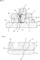
- the holding element 22 comprises a lever which is rotatable about a pivot point D and by means of a spring 23 holds the material measure 4 with a clamping force K in the recess 21, as in FIG. 3 is shown.
- the spring-biased lever urges the material measure 4 to a stop of the recess 21, whereby the material measure 4 is defined on the punch 2 is positioned.
- the depth of the recess 21 in the direction Z is adapted to the thickness of the material measure 4 and selected such that the adhesive film 41 protrudes.
- the material measure 4 can also be held elsewhere - eg by means of magnetic force - on the punch 2.
- a first abutment 11 is arranged, on which the punch 2 is supported in the resting state.
- the spring element 3 urges the punch 2 in the direction of the mounting surface 51, ie in the Z direction, to the abutment 11.
- the abutment 11 ensures that the punch 2 is held in a defined Z-position on the base body 1.
- the stamp 2 is shown in the rest position. In this rest position, the material measure 4 is releasably fixed to the punch 2 by means of the holding element 22.
- the base body 1 is positioned on the carrier 5. Positioning in a direction transverse to the Z-direction takes place on a positioning element 52, for example in the form of a pin.
- the main body 1 is placed on the carrier 5.
- a pressing force F is introduced, which urges the punch 2 and thus the material measure 4 to the mounting surface 51.
- the pressing force F is determined by the spring characteristic of the spring element 3 and the spring travel W, by which the punch 2 is moved away from the abutment 11 against the force exerting the spring element 3.
- the spring travel W is thus determined by the Z position of the first abutment 11 and the Z position of a second abutment 6 of the base body 1.
- This second abutment 6 is formed as a stop surface, which is brought into contact with a reference surface 53 of the carrier 5 and limits the Z movement of the basic body.
- the pressure force F is thus determined by the construction of the device itself.
- the material measure 4 is thereby pressed with a defined and reproducible pressure force F on the cultivation surface 51 and glued.
- the position of the first abutment 11 or the second abutment 6 may be configured in a manner not shown on the base body 1 adjustable. This may be advantageous to compensate for different Z-positions (height differences) between the mounting surface 51 and the reference surface 53.
- the material measure After the two-dimensional adhesion of the material measure 4 with the pressure force F to the mounting surface 51, the material measure is detached from the punch 2 by means of the holding element 22 and the device is removed from the carrier 5.
- the carrier 105 is a tape measure on the back of the material measure 4 is to be glued.
- This second device differs from the first device by two further functions integrated therein.
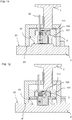
- the first further function is the special design of the first abutment 111.
- the abutment 111 positions in this case the punch 2 on the base body 101 in the rest position according to FIG. 7 in such a way that the material measure 4 is arranged at a distance from the mounting surface 51 when the base body 101 is positioned on the carrier 5. Starting from this rest position - ie in the already positioned state - the abutment 111 is disengaged, so that the force F of the spring element 3 comes into effect and urges the punch 2 with the material measure attached thereto 4 to the mounting surface 51. The pressure force F is thus generated by relaxing the spring element 3.
- the pressing force F is determined by the spring characteristic of the spring element 3 and by the spring travel W, by which the punch 2 is moved away against the mounting surface 51.
- the spring travel W is thus determined by the Z position of the first abutment 111 and by the Z position of a second Abutment 61 of the main body 101.
- This second abutment 61 is formed as a stop surface, which is brought into contact with a reference surface 53 of the carrier 5 and the Z-position of the base body 101 pretends.
- the abutment 111 itself is formed by an eccentrically mounted rod, which is rotatable by means of a handle 8.
- the second further function is that the main body 101 comprises a holder 100, on which the main body 101 is fastened adjustable together with the punch 2 in the Z direction.
- the adjustment takes place in the example by means of a screw 7.
- the holder 100 is positioned relative to the carrier 5.
- the holder 100 has the abutment 61 in the form of a stop surface, which are placed on corresponding reference surfaces 53 of the carrier 5, which are aligned parallel to the mounting surface 51 when gluing the measuring standard 4.
- FIGS. 11 and 12 show, position differences of the cultivation surface 51 can be compensated in the Z direction.
- the material measure 4 is formed, for example, band-shaped, in particular as a short steel strip with a length of a few cm.
Abstract
Die vorliegende Erfindung betrifft eine Vorrichtung und ein Verfahren zum Anbringen einer Maßverkörperung (4) an eine Anbaufläche (51) eines Trägers (5) durch Kleben. Die Vorrichtung umfasst einen Grundkörper (1) und einen Stempel (2), der relativ zum Grundkörper (1) längs einer Achse (Z) senkrecht zur Anbaufläche (51) verlagerbar ist, und der ein Halteelement (22) zur lösbaren Halterung der Maßverkörperung (4) aufweist. Ein Federelement (3) ist derart zwischen dem Grundkörper (1) und dem Stempel (2) angeordnet, dass das Federelement (3) beim Anbringen der Maßverkörperung (4) auf den Stempel (2) eine Druckkraft (F) längs der Achse (Z) hin zu der Anbaufläche (51) ausübt.The present invention relates to an apparatus and a method for attaching a material measure (4) to a mounting surface (51) of a carrier (5) by gluing. The device comprises a base body (1) and a punch (2), which is displaceable relative to the base body (1) along an axis (Z) perpendicular to the mounting surface (51), and a holding element (22) for releasably holding the material measure ( 4). A spring element (3) is arranged between the base body (1) and the punch (2) such that the spring element (3) when attaching the material measure (4) on the punch (2) a compressive force (F) along the axis (Z ) to the acreage (51).
Description
Die vorliegende Erfindung betrifft eine Vorrichtung zum Anbringen einer Maßverkörperung gemäß den Merkmalen des Anspruchs 1 sowie ein Verfahren zum Anbringen einer Maßverkörperung gemäß den Merkmalen des Anspruchs 8.The present invention relates to a device for attaching a material measure according to the features of
Die
Beim Anbringen der Maßverkörperung muss der Stempel gegen eine Federkraft niedergedrückt werden. Die auf die Maßverkörperung dabei einwirkende Andruckkraft ist abhängig von der Kraft, die der Anwender auf den Stempel ausübt.When attaching the material measure, the punch must be depressed against a spring force. The on the measuring standard here acting pressure force is dependent on the force exerted by the user on the stamp.
Der vorliegenden Erfindung liegt die Aufgabe zugrunde, eine Vorrichtung zum Anbringen einer Maßverkörperung einer Positionsmesseinrichtung anzugeben, die kompakt aufgebaut ist und mit der eine Maßverkörperung an einer Anbaufläche eines Trägers reproduzierbar aufgebracht werden kann, so dass damit eine genaue Positionsmessung ermöglicht wird.The present invention has for its object to provide a device for attaching a material measure of a position measuring device, which is compact and with which a material measure on a mounting surface of a carrier can be reproducibly applied, so that thus an accurate position measurement is possible.
Diese Aufgabe wird erfindungsgemäß durch die Vorrichtung mit den Merkmalen des Anspruchs 1 gelöst. Diese Vorrichtung umfasst einen Grundkörper und einen Stempel, der relativ zum Grundkörper längs einer Achse senkrecht zur Anbaufläche verlaufend verlagerbar ist, und der ein Halteelement zur lösbaren Halterung der Maßverkörperung aufweist. Zwischen dem Grundkörper und dem Stempel ist ein Federelement derart angeordnet, dass das Federelement beim Anbringen der Maßverkörperung eine Druckkraft längs der Achse hin zu der Anbaufläche auf den Stempel ausübt. Mit dieser Vorrichtung kann eine Maßverkörperung reproduzierbar aufgeklebt werden, wobei zwischen der Maßverkörperung und der Anbaufläche ein Klebefilm angeordnet ist, auf den eine durch die Konstruktion der Vorrichtung vorgegebene Andruckkraft wirkt.This object is achieved by the device with the features of
Vorzugsweise besteht das Federelement aus einer Anordnung von mehreren Druckfedern, die in gegenseitigem Abstand zueinander zwischen dem Grundkörper und dem Stempel verteilt angeordnet sind.Preferably, the spring element consists of an arrangement of a plurality of compression springs, which are arranged distributed at a mutual distance between the base body and the stamp.
Das Halteelement ist bevorzugt ein Klemmmechanismus, der dazu ausgebildet ist, die Maßverkörperung derart am Stempel klemmend zu halten, dass die Maßverkörperung beim Anbringen mit der Druckkraft auf die Anbaufläche gedrängt wird und die Maßverkörperung nach erfolgtem Anbringen vom Stempel gelöst werden kann.The holding element is preferably a clamping mechanism, which is designed to clamp the material measure so as to hold the punch so that the material measure is urged when attaching the pressure force on the cultivation surface and the material measure can be solved after successful attachment of the stamp.
Die erfindungsgemäße Vorrichtung kann dazu ausgebildet sein, die Druckkraft durch Verlagerung des Stempels relativ zum Grundkörper längs der Achse zu erzeugen, indem sich das Federelement dabei spannt, oder die Vorrichtung kann dazu ausgebildet sein, die Druckkraft durch Verlagerung des Stempels relativ zum Grundkörper längs der Achse zu erzeugen, wobei sich das Federelement dabei entspannt.The device according to the invention can be designed to generate the pressure force by displacement of the punch relative to the main body along the axis by the spring element thereby biases, or the device can be configured to the compressive force by displacement of the punch relative to the main body along the axis to produce, with the spring element relaxes it.
Bei beiden Möglichkeiten ist der Weg (Federweg) bei der Verlagerung des Stempels längs der Achse durch ein erstes Widerlager des Grundkörpers und ein zweites Widerlager des Grundkörpers vorgegeben. Das erste Widerlager positioniert den Stempel in einer Position längs der Achse am Grundkörper, von der aus die Verlagerung ermöglicht wird und das zweite Widerlager ist dazu ausgebildet, den Grundkörper beim Anbringen der Maßverkörperung bezüglich des Trägers längs der Achse zu positionieren.In both ways, the path (travel) in the displacement of the punch along the axis by a first abutment of the body and a second abutment of the body is specified. The first abutment positions the stamper in a position along the axis on the body from which the displacement is made possible, and the second abutment is adapted to position the body when attaching the material measure with respect to the carrier along the axis.
Die Maßverkörperung ist vorzugsweise ein kurzer Maßstab, mit einer Länge von wenigen cm, bestehend aus Stahl oder Glas bzw. Glaskeramik. Die Maßverkörperung trägt eine Messteilung in Form einer absoluten Codierung oder einer inkrementalen Codierung. Darüber hinaus kann die Messteilung lichtelektrisch, magnetisch, kapazitiv oder induktiv abtastbar ausgebildet sein.The material measure is preferably a short scale, with a length of a few cm, consisting of steel or glass or glass ceramic. The material measure carries a measuring graduation in the form of an absolute coding or an incremental coding. In addition, the measurement graduation can be formed photoelectric, magnetic, capacitive or inductive scannable.
Ein Verfahren zum Anbringen einer Maßverkörperung mit der erfindungsgemäß ausgebildeten Vorrichtung ist im Anspruch 8 angegeben.A method for attaching a material measure with the inventively designed device is specified in
Das Verfahren umfasst folgende Verfahrensschritte:
- Halterung der Maßverkörperung an dem Stempel mittels des Halteelementes;
- Positionieren des Grundkörpers am Träger längs der Achse und Ausüben der Druckkraft durch das Federelement, welche die Maßverkörperung längs der Achse an die Anbaufläche drängt;
- Lösen der Maßverkörperung vom Stempel.
- Holder of the material measure on the stamp by means of the holding element;
- Positioning the base body on the carrier along the axis and exerting the compressive force by the spring element, which urges the material measure along the axis of the mounting surface;
- Release the measuring scale from the stamp.
Die Maßverkörperung ist an ihrer Unterseite, also der Anbaufläche gegenüberliegend, mit einem Klebefilm versehen, so dass die Maßverkörperung beim Aufbringen der Druckkraft aufgeklebt wird. Nach diesem Aufkleben erfolgt das Lösen der Maßverkörperung vom Stempel.The material measure is on its underside, so the acreage opposite, provided with an adhesive film, so that the Material measure is adhered when applying the pressure force. After this sticking takes place the release of the material measure from the stamp.
Vorteilhafte Ausführungen der Erfindung ergeben sich aus den Maßnahmen, die in den abhängigen Ansprüchen aufgeführt sind.Advantageous embodiments of the invention will become apparent from the measures listed in the dependent claims.
Weitere Einzelheiten und Vorteile der vorliegenden Erfindung werden anhand der nachfolgenden Beschreibung von Ausführungsbeispielen in Verbindung mit den Figuren erläutert.Further details and advantages of the present invention will be explained with reference to the following description of exemplary embodiments in conjunction with the figures.
Es zeigt
Figur 1- einen Querschnitt einer ersten erfindungsgemäßen Vorrichtung zum Anbringen einer Maßverkörperung;
Figur 2- die erste Vorrichtung gemäß
Figur 1 Figur 3- einen vergrößert dargestellten Ausschnitt aus der
Figur 2 Figur 4- die erste Vorrichtung von unten betrachtet;
Figur 5- einen Längsschnitt V - V der ersten Vorrichtung;
Figur 6- die erste Vorrichtung beim Anbringen einer Maßverkörperung;
Figur 7- einen Querschnitt einer zweiten erfindungsgemäßen Vorrichtung zum Anbringen einer Maßverkörperung;
Figur 8- die zweite Vorrichtung beim Anbringen einer Maßverkörperung auf einen Träger;
- Figur 9
- eine weitere Ansicht der zweiten Vorrichtung;
- Figur 10
- einen Längsschnitt X - X der zweiten Vorrichtung;
Figur 11- die zweite Vorrichtung beim Anbringen einer Maßverkörperung auf einen Träger;
- Figur 12
- die zweite Vorrichtung beim Anbringen einer Maßverkörperung auf einen Träger.
- FIG. 1
- a cross-section of a first device according to the invention for attaching a material measure;
- FIG. 2
- the first device according to
FIG. 1 when attaching a material measure to a carrier; - FIG. 3
- an enlarged detail of the
FIG. 2 ; - FIG. 4
- the first device viewed from below;
- FIG. 5
- a longitudinal section V - V of the first device;
- FIG. 6
- the first device when attaching a material measure;
- FIG. 7
- a cross section of a second device according to the invention for attaching a material measure;
- FIG. 8
- the second device when attaching a material measure to a carrier;
- FIG. 9
- another view of the second device;
- FIG. 10
- a longitudinal section X - X of the second device;
- FIG. 11
- the second device when attaching a material measure to a carrier;
- FIG. 12
- the second device when attaching a material measure on a carrier.
Die Erfindung wird anhand zweier Ausführungsbeispiele erläutert. Bei dem ersten Ausführungsbeispiel wird die erfindungsgemäße Vorrichtung erste Vorrichtung genannt und bei dem zweiten Ausführungsbeispiel zweite Vorrichtung. Funktionsgleiche Elemente sind in den beiden Ausführungsbeispielen jeweils mit dem gleichen Bezugszeichen versehen. Den erfindungsgemäßen Vorrichtungen ist gemeinsam, dass sie dazu ausgelegt sind eine Maßverkörperung 4 an einer Anbaufläche 51 durch Kleben anzubringen, wozu die Vorrichtungen die Maßverkörperung 4 mit einer definierten Andruckkraft F auf die Anbaufläche 51 andrücken. Zur klebenden Befestigung der Maßverkörperung 4 ist diese an seiner Unterseite und / oder die Anbaufläche 51 mit einem Klebefilm 41 versehen.The invention will be explained with reference to two embodiments. In the first embodiment, the device according to the invention is called first device and in the second embodiment second device. Functionally identical elements are each provided with the same reference numerals in the two embodiments. The devices according to the invention have in common that they are designed to attach a
Das erste Ausführungsbeispiel der erfindungsgemäßen Vorrichtung sowie das damit ausgeführte Verfahren wird nachfolgend anhand der
Der Stempel 2 weist ein Halteelement 22 zur lösbaren Halterung der Maßverkörperung 4 auf. Das Halteelement 22 ist dazu ausgebildet, die Maßverkörperung 4 so lange am Stempel 2 klemmend zu halten, bis diese an der Anbaufläche 51 befestigt ist und die Klemmung der Maßverkörperung 4 am Halteelement 22 ist nach erfolgter Befestigung der Maßverkörperung 4 an der Anbaufläche 51 aufhebbar. Im dargestellten Ausführungsbeispiel ist das Halteelement 22 ein Klemmmechanismus. Zur Aufnahme der Maßverkörperung 4 am Stempel 2 weist dieser eine Ausnehmung 21 auf. Zur Fixierung der Maßverkörperung 4 in dieser Ausnehmung 21 des Stempels 2 umfasst das Halteelement 22 einen Hebel, der um einen Drehpunkt D drehbar ist und mittels einer Feder 23 die Maßverkörperung 4 mit einer Klemmkraft K in der Ausnehmung 21 hält, wie in
In nicht gezeigter Weise kann die Maßverkörperung 4 auch anderweitig - z.B. mittels Magnetkraft - am Stempel 2 lösbar gehalten werden.
Am Grundkörper 1 ist ein erstes Widerlager 11 angeordnet, an dem sich der Stempel 2 im Ruhezustand abstützt. Das Federelement 3 drängt den Stempel 2 in Richtung der Anbaufläche 51, also in Z-Richtung, an das Widerlager 11. Das Widerlager 11 sorgt dafür, dass der Stempel 2 in einer definierten Z-Position am Grundkörper 1 gehalten wird. In
On the
In einem nächsten Schritt wird der Grundkörper 1 am Träger 5 positioniert. Die Positionierung in einer Richtung quer zur Z-Richtung erfolgt an einem Positionierelement 52, beispielsweise stiftförmig ausgeführt. Im Weiteren wird der Grundkörper 1 auf den Träger 5 aufgesetzt. Dabei wird eine Andruckkraft F eingeleitet, welche den Stempel 2 und somit die Maßverkörperung 4 an die Anbaufläche 51 drängt. Die Andruckkraft F ist bestimmt durch die Federkennlinie des Federelementes 3 und den Federweg W, um den der Stempel 2 gegen die das Federelement 3 ausübende Kraft vom Widerlager 11 wegbewegt wird. Der Federweg W ist also bestimmt durch die Z-Position des ersten Widerlagers 11 und der Z-Position eines zweiten Widerlagers 6 des Grundkörpers 1. Dieses zweite Widerlager 6 ist als Anschlagfläche ausgebildet, welche mit einer Bezugsfläche 53 des Trägers 5 in Kontakt gebracht wird und die Z-Bewegung des Grundkörpers begrenzt.In a next step, the
Die Andruckkraft F ist somit von der Konstruktion der Vorrichtung selbst bestimmt. Die Maßverkörperung 4 wird dadurch mit einer definierten und reproduzierbaren Andruckkraft F auf die Anbaufläche 51 gedrückt und aufgeklebt.The pressure force F is thus determined by the construction of the device itself. The
Die Lage des ersten Widerlagers 11 oder des zweiten Widerlagers 6 kann in nicht gezeigter Weise am Grundkörper 1 justierbar ausgestaltet sein. Dies kann vorteilhaft sein, um unterschiedliche Z-Positionen (Höhenunterschiede) zwischen der Anbaufläche 51 und der Bezugsfläche 53 auszugleichen.The position of the
Zum Aufkleben der Maßverkörperung 4 auf die Anbaufläche 51 mit der definierten und reproduzierbaren Andruckkraft F ist diese auf ihrer Unterseite mit einem Klebefilm 41 versehen, wie in
Nach erfolgter flächiger Anhaftung der Maßverkörperung 4 mit der Andruckkraft F an die Anbaufläche 51 wird die Maßverkörperung vom Stempel 2 mittels des Halteelementes 22 gelöst und die Vorrichtung von dem Träger 5 entfernt.After the two-dimensional adhesion of the
In
Nachfolgend wird anhand der
Diese zweite Vorrichtung unterscheidet sich von der ersten Vorrichtung durch zwei weitere darin integrierte Funktionen.This second device differs from the first device by two further functions integrated therein.
Die erste weitere Funktion ist die besondere Ausbildung des ersten Widerlagers 111. Das Widerlager 111 positioniert in diesem Fall den Stempel 2 an dem Grundkörper 101 in der Ruhelage gemäß
Die Andruckkraft F ist bestimmt durch die Federkennlinie des Federelementes 3 und durch den Federweg W, um den der Stempel 2 gegen die Anbaufläche 51 wegbewegt wird. Der Federweg W ist also bestimmt durch die Z-Position des ersten Widerlagers 111 und durch die Z-Position eines zweiten Widerlagers 61 des Grundkörpers 101. Dieses zweite Widerlager 61 ist als Anschlagfläche ausgebildet, welche mit einer Bezugsfläche 53 des Trägers 5 in Kontakt gebracht wird und die Z-Position des Grundkörpers 101 vorgibt.The pressing force F is determined by the spring characteristic of the
Im dargestellten Ausführungsbeispiel dient zum außer Eingriff bringen des Widerlagers 111 ein Exzenter. Insbesondere ist das Widerlager 111 selbst von einer exzentrisch gelagerten Stange gebildet, die mittels einer Handhabe 8 verdrehbar ist.In the illustrated embodiment is used to disengage the
Die zweite weitere Funktion besteht darin, dass der Grundkörper 101 eine Halterung 100 umfasst, an welcher der Grundkörper 101 gemeinsam mit dem Stempel 2 in Z-Richtung justierbar befestigt ist. Die Justierung erfolgt im Beispiel mittels einer Schraube 7. Bei dem Anbringen der Maßverkörperung 4 an dem Träger 5 wird die Halterung 100 gegenüber dem Träger 5 positioniert. In diesem Fall weist die Halterung 100 das Widerlager 61 in Form einer Anschlagfläche auf, welche beim Aufkleben der Maßverkörperung 4 auf korrespondierende Bezugsflächen 53 des Trägers 5, die parallel zur Anbaufläche 51 ausgerichtet sind, aufgesetzt werden. Wie die
Die Maßverkörperung 4 ist beispielsweise bandförmig ausgebildet, insbesondere als ein kurzes Stahlband mit einer Länge von wenigen cm.The
Claims (10)
Applications Claiming Priority (1)
| Application Number | Priority Date | Filing Date | Title |
|---|---|---|---|
| DE102016203509.6A DE102016203509A1 (en) | 2016-03-03 | 2016-03-03 | Device and method for attaching a material measure |
Publications (3)
| Publication Number | Publication Date |
|---|---|
| EP3214413A2 true EP3214413A2 (en) | 2017-09-06 |
| EP3214413A3 EP3214413A3 (en) | 2017-09-20 |
| EP3214413B1 EP3214413B1 (en) | 2019-08-14 |
Family
ID=57460386
Family Applications (1)
| Application Number | Title | Priority Date | Filing Date |
|---|---|---|---|
| EP16201603.4A Active EP3214413B1 (en) | 2016-03-03 | 2016-12-01 | Device and method for applying a solid measure |
Country Status (4)
| Country | Link |
|---|---|
| EP (1) | EP3214413B1 (en) |
| JP (1) | JP6835629B2 (en) |
| DE (1) | DE102016203509A1 (en) |
| ES (1) | ES2743300T3 (en) |
Cited By (1)
| Publication number | Priority date | Publication date | Assignee | Title |
|---|---|---|---|---|
| CN110017744A (en) * | 2019-03-26 | 2019-07-16 | 四川宁江山川机械有限责任公司 | A kind of spring base weld size test measuring device and its detection method |
Families Citing this family (1)
| Publication number | Priority date | Publication date | Assignee | Title |
|---|---|---|---|---|
| CN113251891B (en) * | 2021-05-19 | 2021-12-17 | 广州中益机械有限公司 | Convenient efficient part measuring mechanism |
Citations (1)
| Publication number | Priority date | Publication date | Assignee | Title |
|---|---|---|---|---|
| DE102015006222A1 (en) | 2014-06-09 | 2015-12-10 | Mitutoyo Corporation | Measuring tape applicator and measuring tape application method |
Family Cites Families (2)
| Publication number | Priority date | Publication date | Assignee | Title |
|---|---|---|---|---|
| GB8820777D0 (en) * | 1988-09-02 | 1988-10-05 | Renishaw Plc | Tape scale applicator |
| DE10229888B4 (en) * | 2002-07-03 | 2010-09-30 | Dr. Johannes Heidenhain Gmbh | Apparatus and method for attaching a scale or scale carrier or scale guide and scale, scale carrier or scale guide or protective tape therefor |
-
2016
- 2016-03-03 DE DE102016203509.6A patent/DE102016203509A1/en not_active Withdrawn
- 2016-12-01 ES ES16201603T patent/ES2743300T3/en active Active
- 2016-12-01 EP EP16201603.4A patent/EP3214413B1/en active Active
-
2017
- 2017-03-02 JP JP2017039056A patent/JP6835629B2/en active Active
Patent Citations (1)
| Publication number | Priority date | Publication date | Assignee | Title |
|---|---|---|---|---|
| DE102015006222A1 (en) | 2014-06-09 | 2015-12-10 | Mitutoyo Corporation | Measuring tape applicator and measuring tape application method |
Cited By (2)
| Publication number | Priority date | Publication date | Assignee | Title |
|---|---|---|---|---|
| CN110017744A (en) * | 2019-03-26 | 2019-07-16 | 四川宁江山川机械有限责任公司 | A kind of spring base weld size test measuring device and its detection method |
| CN110017744B (en) * | 2019-03-26 | 2024-04-26 | 四川宁江山川机械有限责任公司 | Measuring tool for welding size of spring seat and detecting method thereof |
Also Published As
| Publication number | Publication date |
|---|---|
| EP3214413A3 (en) | 2017-09-20 |
| ES2743300T3 (en) | 2020-02-18 |
| DE102016203509A1 (en) | 2017-09-07 |
| JP6835629B2 (en) | 2021-02-24 |
| EP3214413B1 (en) | 2019-08-14 |
| JP2017161520A (en) | 2017-09-14 |
Similar Documents
| Publication | Publication Date | Title |
|---|---|---|
| EP2537067B1 (en) | Method and device for active wedge error compensation between two objects that can be positioned substantially parallel to each other | |
| EP3237877A1 (en) | Device for carrying out a bending test | |
| EP3010665B1 (en) | Bending tool | |
| DE102013012389B4 (en) | Device and method for mounting a label | |
| DE10229888B4 (en) | Apparatus and method for attaching a scale or scale carrier or scale guide and scale, scale carrier or scale guide or protective tape therefor | |
| EP3214413B1 (en) | Device and method for applying a solid measure | |
| EP1860424B1 (en) | Self-aligning scanning probes for scanning probe microscope | |
| DE10229885B4 (en) | Method and apparatus for attaching a scale or scale carrier or scale guide | |
| EP0332807A2 (en) | Device to determine the position of workpiece-surfaces | |
| DE102013104974B4 (en) | Arrangement with a fastening unit and a sensor | |
| EP4030147B1 (en) | Length measuring device | |
| DE102017104638B4 (en) | Device for folding over excess material from a lamination around an edge area of a workpiece and a corresponding method | |
| DE102004035299A1 (en) | Mounting aid of a position measuring device | |
| DE102019133692A1 (en) | Teaching for attaching a component to a carrier component | |
| DE10204611B4 (en) | Method and apparatus for attaching a scale or scale carrier | |
| EP2006634B1 (en) | Device to hold components, in particular sheet metal components for vehicle body work, for measuring in a reference position | |
| EP3563160B1 (en) | Adapter device, holding clamp, and method for positioning a conductor pair of a cable to be measured | |
| DE10256430B3 (en) | Punch unit e.g. for punch press has punch head held by holding element at points, and punch taken only into guide plate | |
| DE102010051978B3 (en) | Device for determination of retaining force while producing joint connection by joining device, has male-die and down-holder, where device is formed on female die of joining device | |
| DE102016103461B4 (en) | Magnetizable support device and method for grinding a plate-shaped workpiece with such a support device | |
| DE3108251A1 (en) | DEVICE FOR LOCALLY ALIGNING A WORKPIECE IN TWO COORDINATE AXES WITH AT LEAST ONE TOOL OF A MACHINE TOOL | |
| DE102012001848B4 (en) | Method for aligning a machining device and machining device for machining a workpiece | |
| DE4321980C2 (en) | Device for freely bending a workpiece | |
| DE102014105021A1 (en) | Hand press for pressing, joining or assembling workpieces | |
| DD216155A1 (en) | DEVICE FOR RASTERING AND CONTACTING COMPONENT TERMINALS |
Legal Events
| Date | Code | Title | Description |
|---|---|---|---|
| PUAI | Public reference made under article 153(3) epc to a published international application that has entered the european phase |
Free format text: ORIGINAL CODE: 0009012 |
|
| STAA | Information on the status of an ep patent application or granted ep patent |
Free format text: STATUS: REQUEST FOR EXAMINATION WAS MADE |
|
| PUAL | Search report despatched |
Free format text: ORIGINAL CODE: 0009013 |
|
| 17P | Request for examination filed |
Effective date: 20161201 |
|
| AK | Designated contracting states |
Kind code of ref document: A2 Designated state(s): AL AT BE BG CH CY CZ DE DK EE ES FI FR GB GR HR HU IE IS IT LI LT LU LV MC MK MT NL NO PL PT RO RS SE SI SK SM TR |
|
| AX | Request for extension of the european patent |
Extension state: BA ME |
|
| STAA | Information on the status of an ep patent application or granted ep patent |
Free format text: STATUS: EXAMINATION IS IN PROGRESS |
|
| AK | Designated contracting states |
Kind code of ref document: A3 Designated state(s): AL AT BE BG CH CY CZ DE DK EE ES FI FR GB GR HR HU IE IS IT LI LT LU LV MC MK MT NL NO PL PT RO RS SE SI SK SM TR |
|
| AX | Request for extension of the european patent |
Extension state: BA ME |
|
| RIC1 | Information provided on ipc code assigned before grant |
Ipc: G01D 5/347 20060101AFI20170811BHEP |
|
| 17Q | First examination report despatched |
Effective date: 20170919 |
|
| RBV | Designated contracting states (corrected) |
Designated state(s): AL AT BE BG CH CY CZ DE DK EE ES FI FR GB GR HR HU IE IS IT LI LT LU LV MC MK MT NL NO PL PT RO RS SE SI SK SM TR |
|
| GRAP | Despatch of communication of intention to grant a patent |
Free format text: ORIGINAL CODE: EPIDOSNIGR1 |
|
| STAA | Information on the status of an ep patent application or granted ep patent |
Free format text: STATUS: GRANT OF PATENT IS INTENDED |
|
| INTG | Intention to grant announced |
Effective date: 20190404 |
|
| GRAS | Grant fee paid |
Free format text: ORIGINAL CODE: EPIDOSNIGR3 |
|
| GRAA | (expected) grant |
Free format text: ORIGINAL CODE: 0009210 |
|
| STAA | Information on the status of an ep patent application or granted ep patent |
Free format text: STATUS: THE PATENT HAS BEEN GRANTED |
|
| AK | Designated contracting states |
Kind code of ref document: B1 Designated state(s): AL AT BE BG CH CY CZ DE DK EE ES FI FR GB GR HR HU IE IS IT LI LT LU LV MC MK MT NL NO PL PT RO RS SE SI SK SM TR |
|
| REG | Reference to a national code |
Ref country code: GB Ref legal event code: FG4D Free format text: NOT ENGLISH |
|
| REG | Reference to a national code |
Ref country code: CH Ref legal event code: EP Ref country code: AT Ref legal event code: REF Ref document number: 1167566 Country of ref document: AT Kind code of ref document: T Effective date: 20190815 |
|
| REG | Reference to a national code |
Ref country code: IE Ref legal event code: FG4D Free format text: LANGUAGE OF EP DOCUMENT: GERMAN |
|
| REG | Reference to a national code |
Ref country code: DE Ref legal event code: R096 Ref document number: 502016006065 Country of ref document: DE |
|
| REG | Reference to a national code |
Ref country code: NL Ref legal event code: MP Effective date: 20190814 |
|
| REG | Reference to a national code |
Ref country code: LT Ref legal event code: MG4D |
|
| PG25 | Lapsed in a contracting state [announced via postgrant information from national office to epo] |
Ref country code: FI Free format text: LAPSE BECAUSE OF FAILURE TO SUBMIT A TRANSLATION OF THE DESCRIPTION OR TO PAY THE FEE WITHIN THE PRESCRIBED TIME-LIMIT Effective date: 20190814 Ref country code: HR Free format text: LAPSE BECAUSE OF FAILURE TO SUBMIT A TRANSLATION OF THE DESCRIPTION OR TO PAY THE FEE WITHIN THE PRESCRIBED TIME-LIMIT Effective date: 20190814 Ref country code: LT Free format text: LAPSE BECAUSE OF FAILURE TO SUBMIT A TRANSLATION OF THE DESCRIPTION OR TO PAY THE FEE WITHIN THE PRESCRIBED TIME-LIMIT Effective date: 20190814 Ref country code: PT Free format text: LAPSE BECAUSE OF FAILURE TO SUBMIT A TRANSLATION OF THE DESCRIPTION OR TO PAY THE FEE WITHIN THE PRESCRIBED TIME-LIMIT Effective date: 20191216 Ref country code: SE Free format text: LAPSE BECAUSE OF FAILURE TO SUBMIT A TRANSLATION OF THE DESCRIPTION OR TO PAY THE FEE WITHIN THE PRESCRIBED TIME-LIMIT Effective date: 20190814 Ref country code: BG Free format text: LAPSE BECAUSE OF FAILURE TO SUBMIT A TRANSLATION OF THE DESCRIPTION OR TO PAY THE FEE WITHIN THE PRESCRIBED TIME-LIMIT Effective date: 20191114 Ref country code: NL Free format text: LAPSE BECAUSE OF FAILURE TO SUBMIT A TRANSLATION OF THE DESCRIPTION OR TO PAY THE FEE WITHIN THE PRESCRIBED TIME-LIMIT Effective date: 20190814 Ref country code: NO Free format text: LAPSE BECAUSE OF FAILURE TO SUBMIT A TRANSLATION OF THE DESCRIPTION OR TO PAY THE FEE WITHIN THE PRESCRIBED TIME-LIMIT Effective date: 20191114 |
|
| REG | Reference to a national code |
Ref country code: ES Ref legal event code: FG2A Ref document number: 2743300 Country of ref document: ES Kind code of ref document: T3 Effective date: 20200218 |
|
| PG25 | Lapsed in a contracting state [announced via postgrant information from national office to epo] |
Ref country code: IS Free format text: LAPSE BECAUSE OF FAILURE TO SUBMIT A TRANSLATION OF THE DESCRIPTION OR TO PAY THE FEE WITHIN THE PRESCRIBED TIME-LIMIT Effective date: 20191214 Ref country code: AL Free format text: LAPSE BECAUSE OF FAILURE TO SUBMIT A TRANSLATION OF THE DESCRIPTION OR TO PAY THE FEE WITHIN THE PRESCRIBED TIME-LIMIT Effective date: 20190814 Ref country code: GR Free format text: LAPSE BECAUSE OF FAILURE TO SUBMIT A TRANSLATION OF THE DESCRIPTION OR TO PAY THE FEE WITHIN THE PRESCRIBED TIME-LIMIT Effective date: 20191115 Ref country code: LV Free format text: LAPSE BECAUSE OF FAILURE TO SUBMIT A TRANSLATION OF THE DESCRIPTION OR TO PAY THE FEE WITHIN THE PRESCRIBED TIME-LIMIT Effective date: 20190814 Ref country code: RS Free format text: LAPSE BECAUSE OF FAILURE TO SUBMIT A TRANSLATION OF THE DESCRIPTION OR TO PAY THE FEE WITHIN THE PRESCRIBED TIME-LIMIT Effective date: 20190814 |
|
| PG25 | Lapsed in a contracting state [announced via postgrant information from national office to epo] |
Ref country code: TR Free format text: LAPSE BECAUSE OF FAILURE TO SUBMIT A TRANSLATION OF THE DESCRIPTION OR TO PAY THE FEE WITHIN THE PRESCRIBED TIME-LIMIT Effective date: 20190814 |
|
| PG25 | Lapsed in a contracting state [announced via postgrant information from national office to epo] |
Ref country code: PL Free format text: LAPSE BECAUSE OF FAILURE TO SUBMIT A TRANSLATION OF THE DESCRIPTION OR TO PAY THE FEE WITHIN THE PRESCRIBED TIME-LIMIT Effective date: 20190814 Ref country code: EE Free format text: LAPSE BECAUSE OF FAILURE TO SUBMIT A TRANSLATION OF THE DESCRIPTION OR TO PAY THE FEE WITHIN THE PRESCRIBED TIME-LIMIT Effective date: 20190814 Ref country code: DK Free format text: LAPSE BECAUSE OF FAILURE TO SUBMIT A TRANSLATION OF THE DESCRIPTION OR TO PAY THE FEE WITHIN THE PRESCRIBED TIME-LIMIT Effective date: 20190814 Ref country code: IT Free format text: LAPSE BECAUSE OF FAILURE TO SUBMIT A TRANSLATION OF THE DESCRIPTION OR TO PAY THE FEE WITHIN THE PRESCRIBED TIME-LIMIT Effective date: 20190814 Ref country code: RO Free format text: LAPSE BECAUSE OF FAILURE TO SUBMIT A TRANSLATION OF THE DESCRIPTION OR TO PAY THE FEE WITHIN THE PRESCRIBED TIME-LIMIT Effective date: 20190814 |
|
| PG25 | Lapsed in a contracting state [announced via postgrant information from national office to epo] |
Ref country code: SK Free format text: LAPSE BECAUSE OF FAILURE TO SUBMIT A TRANSLATION OF THE DESCRIPTION OR TO PAY THE FEE WITHIN THE PRESCRIBED TIME-LIMIT Effective date: 20190814 Ref country code: SM Free format text: LAPSE BECAUSE OF FAILURE TO SUBMIT A TRANSLATION OF THE DESCRIPTION OR TO PAY THE FEE WITHIN THE PRESCRIBED TIME-LIMIT Effective date: 20190814 Ref country code: IS Free format text: LAPSE BECAUSE OF FAILURE TO SUBMIT A TRANSLATION OF THE DESCRIPTION OR TO PAY THE FEE WITHIN THE PRESCRIBED TIME-LIMIT Effective date: 20200224 Ref country code: CZ Free format text: LAPSE BECAUSE OF FAILURE TO SUBMIT A TRANSLATION OF THE DESCRIPTION OR TO PAY THE FEE WITHIN THE PRESCRIBED TIME-LIMIT Effective date: 20190814 |
|
| REG | Reference to a national code |
Ref country code: DE Ref legal event code: R097 Ref document number: 502016006065 Country of ref document: DE |
|
| PLBE | No opposition filed within time limit |
Free format text: ORIGINAL CODE: 0009261 |
|
| STAA | Information on the status of an ep patent application or granted ep patent |
Free format text: STATUS: NO OPPOSITION FILED WITHIN TIME LIMIT |
|
| PG2D | Information on lapse in contracting state deleted |
Ref country code: IS |
|
| REG | Reference to a national code |
Ref country code: CH Ref legal event code: PL |
|
| 26N | No opposition filed |
Effective date: 20200603 |
|
| REG | Reference to a national code |
Ref country code: BE Ref legal event code: MM Effective date: 20191231 |
|
| PG25 | Lapsed in a contracting state [announced via postgrant information from national office to epo] |
Ref country code: SI Free format text: LAPSE BECAUSE OF FAILURE TO SUBMIT A TRANSLATION OF THE DESCRIPTION OR TO PAY THE FEE WITHIN THE PRESCRIBED TIME-LIMIT Effective date: 20190814 Ref country code: MC Free format text: LAPSE BECAUSE OF FAILURE TO SUBMIT A TRANSLATION OF THE DESCRIPTION OR TO PAY THE FEE WITHIN THE PRESCRIBED TIME-LIMIT Effective date: 20190814 |
|
| PG25 | Lapsed in a contracting state [announced via postgrant information from national office to epo] |
Ref country code: LU Free format text: LAPSE BECAUSE OF NON-PAYMENT OF DUE FEES Effective date: 20191201 Ref country code: FR Free format text: LAPSE BECAUSE OF NON-PAYMENT OF DUE FEES Effective date: 20191231 Ref country code: IE Free format text: LAPSE BECAUSE OF NON-PAYMENT OF DUE FEES Effective date: 20191201 |
|
| PG25 | Lapsed in a contracting state [announced via postgrant information from national office to epo] |
Ref country code: CH Free format text: LAPSE BECAUSE OF NON-PAYMENT OF DUE FEES Effective date: 20191231 Ref country code: BE Free format text: LAPSE BECAUSE OF NON-PAYMENT OF DUE FEES Effective date: 20191231 Ref country code: LI Free format text: LAPSE BECAUSE OF NON-PAYMENT OF DUE FEES Effective date: 20191231 |
|
| PG25 | Lapsed in a contracting state [announced via postgrant information from national office to epo] |
Ref country code: CY Free format text: LAPSE BECAUSE OF FAILURE TO SUBMIT A TRANSLATION OF THE DESCRIPTION OR TO PAY THE FEE WITHIN THE PRESCRIBED TIME-LIMIT Effective date: 20190814 |
|
| PG25 | Lapsed in a contracting state [announced via postgrant information from national office to epo] |
Ref country code: MT Free format text: LAPSE BECAUSE OF FAILURE TO SUBMIT A TRANSLATION OF THE DESCRIPTION OR TO PAY THE FEE WITHIN THE PRESCRIBED TIME-LIMIT Effective date: 20190814 Ref country code: HU Free format text: LAPSE BECAUSE OF FAILURE TO SUBMIT A TRANSLATION OF THE DESCRIPTION OR TO PAY THE FEE WITHIN THE PRESCRIBED TIME-LIMIT; INVALID AB INITIO Effective date: 20161201 |
|
| PG25 | Lapsed in a contracting state [announced via postgrant information from national office to epo] |
Ref country code: MK Free format text: LAPSE BECAUSE OF FAILURE TO SUBMIT A TRANSLATION OF THE DESCRIPTION OR TO PAY THE FEE WITHIN THE PRESCRIBED TIME-LIMIT Effective date: 20190814 |
|
| REG | Reference to a national code |
Ref country code: AT Ref legal event code: MM01 Ref document number: 1167566 Country of ref document: AT Kind code of ref document: T Effective date: 20211201 |
|
| PG25 | Lapsed in a contracting state [announced via postgrant information from national office to epo] |
Ref country code: AT Free format text: LAPSE BECAUSE OF NON-PAYMENT OF DUE FEES Effective date: 20211201 |
|
| PGFP | Annual fee paid to national office [announced via postgrant information from national office to epo] |
Ref country code: ES Payment date: 20230228 Year of fee payment: 7 |
|
| PGFP | Annual fee paid to national office [announced via postgrant information from national office to epo] |
Ref country code: GB Payment date: 20231220 Year of fee payment: 8 |
|
| PGFP | Annual fee paid to national office [announced via postgrant information from national office to epo] |
Ref country code: DE Payment date: 20231214 Year of fee payment: 8 |
|
| PGFP | Annual fee paid to national office [announced via postgrant information from national office to epo] |
Ref country code: ES Payment date: 20240129 Year of fee payment: 8 |