EP3214218A1 - Laundry treating apparatus and control method thereof - Google Patents
Laundry treating apparatus and control method thereof Download PDFInfo
- Publication number
- EP3214218A1 EP3214218A1 EP15855184.6A EP15855184A EP3214218A1 EP 3214218 A1 EP3214218 A1 EP 3214218A1 EP 15855184 A EP15855184 A EP 15855184A EP 3214218 A1 EP3214218 A1 EP 3214218A1
- Authority
- EP
- European Patent Office
- Prior art keywords
- motor
- water
- current
- rotation speed
- main controller
- Prior art date
- Legal status (The legal status is an assumption and is not a legal conclusion. Google has not performed a legal analysis and makes no representation as to the accuracy of the status listed.)
- Pending
Links
- 238000000034 method Methods 0.000 title claims abstract description 26
- XLYOFNOQVPJJNP-UHFFFAOYSA-N water Substances O XLYOFNOQVPJJNP-UHFFFAOYSA-N 0.000 claims abstract description 122
- 239000000126 substance Substances 0.000 abstract description 5
- 238000005406 washing Methods 0.000 description 36
- 238000010586 diagram Methods 0.000 description 6
- 238000001035 drying Methods 0.000 description 6
- 239000008400 supply water Substances 0.000 description 4
- 230000000694 effects Effects 0.000 description 3
- 230000002159 abnormal effect Effects 0.000 description 1
- 238000007792 addition Methods 0.000 description 1
- 239000003990 capacitor Substances 0.000 description 1
- 230000000052 comparative effect Effects 0.000 description 1
- 239000003599 detergent Substances 0.000 description 1
- 238000012986 modification Methods 0.000 description 1
- 230000004048 modification Effects 0.000 description 1
- 238000005086 pumping Methods 0.000 description 1
- 239000007921 spray Substances 0.000 description 1
- 238000006467 substitution reaction Methods 0.000 description 1
Images


Classifications
-
- H—ELECTRICITY
- H02—GENERATION; CONVERSION OR DISTRIBUTION OF ELECTRIC POWER
- H02P—CONTROL OR REGULATION OF ELECTRIC MOTORS, ELECTRIC GENERATORS OR DYNAMO-ELECTRIC CONVERTERS; CONTROLLING TRANSFORMERS, REACTORS OR CHOKE COILS
- H02P29/00—Arrangements for regulating or controlling electric motors, appropriate for both AC and DC motors
- H02P29/02—Providing protection against overload without automatic interruption of supply
-
- D—TEXTILES; PAPER
- D06—TREATMENT OF TEXTILES OR THE LIKE; LAUNDERING; FLEXIBLE MATERIALS NOT OTHERWISE PROVIDED FOR
- D06F—LAUNDERING, DRYING, IRONING, PRESSING OR FOLDING TEXTILE ARTICLES
- D06F33/00—Control of operations performed in washing machines or washer-dryers
- D06F33/30—Control of washing machines characterised by the purpose or target of the control
- D06F33/32—Control of operational steps, e.g. optimisation or improvement of operational steps depending on the condition of the laundry
- D06F33/42—Control of operational steps, e.g. optimisation or improvement of operational steps depending on the condition of the laundry of draining
-
- D—TEXTILES; PAPER
- D06—TREATMENT OF TEXTILES OR THE LIKE; LAUNDERING; FLEXIBLE MATERIALS NOT OTHERWISE PROVIDED FOR
- D06F—LAUNDERING, DRYING, IRONING, PRESSING OR FOLDING TEXTILE ARTICLES
- D06F33/00—Control of operations performed in washing machines or washer-dryers
- D06F33/30—Control of washing machines characterised by the purpose or target of the control
- D06F33/32—Control of operational steps, e.g. optimisation or improvement of operational steps depending on the condition of the laundry
- D06F33/34—Control of operational steps, e.g. optimisation or improvement of operational steps depending on the condition of the laundry of water filling
-
- D—TEXTILES; PAPER
- D06—TREATMENT OF TEXTILES OR THE LIKE; LAUNDERING; FLEXIBLE MATERIALS NOT OTHERWISE PROVIDED FOR
- D06F—LAUNDERING, DRYING, IRONING, PRESSING OR FOLDING TEXTILE ARTICLES
- D06F33/00—Control of operations performed in washing machines or washer-dryers
- D06F33/30—Control of washing machines characterised by the purpose or target of the control
- D06F33/32—Control of operational steps, e.g. optimisation or improvement of operational steps depending on the condition of the laundry
- D06F33/38—Control of operational steps, e.g. optimisation or improvement of operational steps depending on the condition of the laundry of rinsing
-
- D—TEXTILES; PAPER
- D06—TREATMENT OF TEXTILES OR THE LIKE; LAUNDERING; FLEXIBLE MATERIALS NOT OTHERWISE PROVIDED FOR
- D06F—LAUNDERING, DRYING, IRONING, PRESSING OR FOLDING TEXTILE ARTICLES
- D06F37/00—Details specific to washing machines covered by groups D06F21/00 - D06F25/00
- D06F37/30—Driving arrangements
- D06F37/304—Arrangements or adaptations of electric motors
-
- D—TEXTILES; PAPER
- D06—TREATMENT OF TEXTILES OR THE LIKE; LAUNDERING; FLEXIBLE MATERIALS NOT OTHERWISE PROVIDED FOR
- D06F—LAUNDERING, DRYING, IRONING, PRESSING OR FOLDING TEXTILE ARTICLES
- D06F39/00—Details of washing machines not specific to a single type of machines covered by groups D06F9/00 - D06F27/00
- D06F39/08—Liquid supply or discharge arrangements
- D06F39/087—Water level measuring or regulating devices
-
- D—TEXTILES; PAPER
- D06—TREATMENT OF TEXTILES OR THE LIKE; LAUNDERING; FLEXIBLE MATERIALS NOT OTHERWISE PROVIDED FOR
- D06F—LAUNDERING, DRYING, IRONING, PRESSING OR FOLDING TEXTILE ARTICLES
- D06F2103/00—Parameters monitored or detected for the control of domestic laundry washing machines, washer-dryers or laundry dryers
- D06F2103/18—Washing liquid level
-
- D—TEXTILES; PAPER
- D06—TREATMENT OF TEXTILES OR THE LIKE; LAUNDERING; FLEXIBLE MATERIALS NOT OTHERWISE PROVIDED FOR
- D06F—LAUNDERING, DRYING, IRONING, PRESSING OR FOLDING TEXTILE ARTICLES
- D06F2103/00—Parameters monitored or detected for the control of domestic laundry washing machines, washer-dryers or laundry dryers
- D06F2103/24—Spin speed; Drum movements
-
- D—TEXTILES; PAPER
- D06—TREATMENT OF TEXTILES OR THE LIKE; LAUNDERING; FLEXIBLE MATERIALS NOT OTHERWISE PROVIDED FOR
- D06F—LAUNDERING, DRYING, IRONING, PRESSING OR FOLDING TEXTILE ARTICLES
- D06F2103/00—Parameters monitored or detected for the control of domestic laundry washing machines, washer-dryers or laundry dryers
- D06F2103/44—Current or voltage
-
- D—TEXTILES; PAPER
- D06—TREATMENT OF TEXTILES OR THE LIKE; LAUNDERING; FLEXIBLE MATERIALS NOT OTHERWISE PROVIDED FOR
- D06F—LAUNDERING, DRYING, IRONING, PRESSING OR FOLDING TEXTILE ARTICLES
- D06F2105/00—Systems or parameters controlled or affected by the control systems of washing machines, washer-dryers or laundry dryers
- D06F2105/02—Water supply
-
- D—TEXTILES; PAPER
- D06—TREATMENT OF TEXTILES OR THE LIKE; LAUNDERING; FLEXIBLE MATERIALS NOT OTHERWISE PROVIDED FOR
- D06F—LAUNDERING, DRYING, IRONING, PRESSING OR FOLDING TEXTILE ARTICLES
- D06F2105/00—Systems or parameters controlled or affected by the control systems of washing machines, washer-dryers or laundry dryers
- D06F2105/08—Draining of washing liquids
-
- D—TEXTILES; PAPER
- D06—TREATMENT OF TEXTILES OR THE LIKE; LAUNDERING; FLEXIBLE MATERIALS NOT OTHERWISE PROVIDED FOR
- D06F—LAUNDERING, DRYING, IRONING, PRESSING OR FOLDING TEXTILE ARTICLES
- D06F2105/00—Systems or parameters controlled or affected by the control systems of washing machines, washer-dryers or laundry dryers
- D06F2105/46—Drum speed; Actuation of motors, e.g. starting or interrupting
-
- D—TEXTILES; PAPER
- D06—TREATMENT OF TEXTILES OR THE LIKE; LAUNDERING; FLEXIBLE MATERIALS NOT OTHERWISE PROVIDED FOR
- D06F—LAUNDERING, DRYING, IRONING, PRESSING OR FOLDING TEXTILE ARTICLES
- D06F39/00—Details of washing machines not specific to a single type of machines covered by groups D06F9/00 - D06F27/00
- D06F39/08—Liquid supply or discharge arrangements
- D06F39/083—Liquid discharge or recirculation arrangements
- D06F39/085—Arrangements or adaptations of pumps
-
- H—ELECTRICITY
- H02—GENERATION; CONVERSION OR DISTRIBUTION OF ELECTRIC POWER
- H02P—CONTROL OR REGULATION OF ELECTRIC MOTORS, ELECTRIC GENERATORS OR DYNAMO-ELECTRIC CONVERTERS; CONTROLLING TRANSFORMERS, REACTORS OR CHOKE COILS
- H02P1/00—Arrangements for starting electric motors or dynamo-electric converters
- H02P1/16—Arrangements for starting electric motors or dynamo-electric converters for starting dynamo-electric motors or dynamo-electric converters
-
- H—ELECTRICITY
- H02—GENERATION; CONVERSION OR DISTRIBUTION OF ELECTRIC POWER
- H02P—CONTROL OR REGULATION OF ELECTRIC MOTORS, ELECTRIC GENERATORS OR DYNAMO-ELECTRIC CONVERTERS; CONTROLLING TRANSFORMERS, REACTORS OR CHOKE COILS
- H02P3/00—Arrangements for stopping or slowing electric motors, generators, or dynamo-electric converters
- H02P3/06—Arrangements for stopping or slowing electric motors, generators, or dynamo-electric converters for stopping or slowing an individual dynamo-electric motor or dynamo-electric converter
Definitions
- the present invention relates to a laundry treatment machine and a method for controlling the same and, more particularly, to a laundry treatment machine for controlling a motor by sensing a load state based on operation of a pump for drainage and circulation of water, and a method for controlling the laundry treatment machine.
- a laundry treatment machine performs a washing process using friction between laundry and a tub, which rotates by receiving a driving force from a motor, after detergent, water and the laundry are inserted into the tub, and thus can wash the laundry without damaging or tangling the laundry.
- the general laundry treatment machine is configured to supply water into the tub, drain a part of water, supply water again, and then completely drain water as a washing process proceeds.
- the laundry treatment machine To circulate or drain water, the laundry treatment machine includes a pump attached to a drain hose connected to the tub, and the pump includes a motor. As the pump operates due to the motor, water flowing toward a drain is supplied into the tub again through a circulation hose or is drained through the drain hose.
- the pump can brake if the pump continues operating after water is completely drained or stops operating while water is not completely drained.
- the present invention has been made in view of the above problems, and it is an object of the present invention to provide a laundry treatment machine for sensing a voltage applied to a motor included in a pump for circulation and drainage of water to determine a load state of water inside a tub, and controlling operation of the motor depending on the determined load state, and a method for controlling the laundry treatment machine.
- a laundry treatment machine including a motor included in a pump for draining or circulating water, to operate the pump, a motor driver for supplying operation power to the motor, a motor controller for setting a rotation speed of the motor and applying a signal for controlling the motor to the motor driver, a current sensor for measuring a current of the operation power supplied from the motor driver to the motor, a speed sensor for measuring a rotation speed of the motor, a water level sensor for measuring a level of water in a tub, and a main controller for applying a control command to the motor controller to start or stop operation of the motor, wherein the main controller controls the motor to stop by determining a load state of water and determining whether the level of water is zero, based on the current measured by the current sensor and the rotation speed of the motor measured by the speed sensor.
- a method for controlling a laundry treatment machine including operating a motor of a pump to drain water if a water drain command is applied, measuring a current and a rotation speed of the motor, determining whether the current or the rotation speed varies by a specific reference value or more, stopping the motor if the current or the rotation speed varies by the reference value or more, and driving the motor again to complexly drain water after a specific period of time passes.
- a laundry treatment machine and a method for controlling the same achieve the following effect.
- a pump for circulating and draining water since the load of water to be drained is sensed and whether an error occurs due to foreign substances is determined based on a current and a rotation speed of a motor included in the pump, unnecessary operation of the pump may not be performed, damage of the pump due to overload may be prevented, noise due to pump operation in overloaded state may be solved, and the efficiency of pump control may be improved.
- module and “unit” used to signify components are used herein to help the understanding of the components and thus should not be construed as having specific meanings or functions. Accordingly, the terms “module” and “unit” may be used interchangeably.
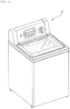
- FIG. 1 is a perspective view of a laundry treatment machine 1 according to an embodiment of the present invention
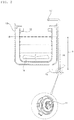
- FIG. 2 is a schematic diagram showing the configurations of a tub and a pump 11 of the laundry treatment machine 1, according to an embodiment of the present invention.
- the laundry treatment machine 1 is a top-loading laundry treatment machine in which laundry is inserted into a tub from above.
- the top-loading laundry treatment machine includes the concept of a washing machine for performing washing, rinsing and spin-drying processes after laundry is inserted, or a drying machine for performing a drying process after wet laundry is inserted, and the following description is focused on the washing machine.
- the washing machine 1 includes a casing for forming the exterior of the washing machine 1, manipulation keys for receiving a variety of control commands input by a user, a control panel for providing a user interface using, for example, a display for displaying information about an operation state of the washing machine 1, and a door for opening or closing an opening through which laundry enters or exits.
- the control panel includes an input unit including a plurality of manipulation keys for manipulating an operation state of the laundry treatment machine 1, and a display unit for displaying the operation state of the laundry treatment machine 1.
- the washing machine 1 includes the tub.
- the tub includes an outer tub 13 for accommodating water, and an inner tub 12 rotatably provided in the outer tub 13 to accommodate laundry.
- the washing machine 1 may include a pulsator 14 rotatably provided at the bottom of the tub and, more particular, at the bottom of the inner tub 12.
- a driving device (not shown) provides a driving force for rotating the inner tub 12 and/or the pulsator 14.
- a clutch (not shown) for selectively delivering the driving force of the driving device may be provided to rotate only the inner tub 12, to rotate only the pulsator 14, or to simultaneously rotate the inner tub 12 and the pulsator 14.
- the inner tub 12 has a plurality of holes (not shown) and thus water supplied into the inner tub 12 flows through the holes to the outer tub 13.
- a water inlet valve (not shown) for opening or closing a water inlet hose (not shown) may be provided to supply water into the tub.
- Water in the outer tub 13 is drained through a drain hose 15, and a drain valve (not shown) for opening or closing the drain hose 15, and the pump 11 for pumping water are provided.
- the pump 11 discharges water through the drain hose 15 to the outside of the washing machine 1, or supplies water through a circulation hose 16 into the tub again, depending on a rotation direction thereof.
- a spray nozzle 17 may be provided at an end of the circulation hose 16 and thus the circulated and re-supplied water may be sprayed.
- a water level sensor (not shown) senses the level of water. In this case, if water is supplied to a first point 18, the level of water corresponds to a height from the location of the drain hose 15 to the first point 18 and a level 19 is measured.
- FIG. 3 is a block diagram of the laundry treatment machine 1 according to an embodiment of the present invention.
- the washing machine 1 includes an input unit 170, an output unit 160, a water level sensor 156, a current sensor 152, a motor controller 120, a motor driver 130, a motor 140, a speed sensor 151, a driving controller 180, a driving device 190, and a main controller 110 for providing overall control to the washing machine 1.
- the washing machine 1 may further include a storage (not shown) for storing data.
- the motor 140 is a motor of the pump 1 mounted on the drain hose 15 for drainage and circulation of water, and the motor controller 120 and the motor driver 130 are used to control operation of the motor 140 of the pump 11.
- the washing machine 1 further includes a plurality of sensors and additional devices related to the driving device 190, and other elements such as a water inlet valve and a drain valve, descriptions thereof are omitted herein and the following description is focused on a configuration for controlling the pump 11.
- the input unit 170 includes a plurality of manipulation keys provided on the control panel, and may further include a specific input means such as a touchpad.
- the input unit 170 inputs setting data such as a washing mode, a washing temperature, a water level, or a reservation time, and inputs a control command for starting or stopping operation of the washing machine 1 depending on the setting data.
- setting data such as a washing mode, a washing temperature, a water level, or a reservation time
- the output unit 160 outputs the setting data input through the input unit 170, e.g., the washing mode, the washing temperature, or the water level, and outputs process information such as a current washing process state and a remaining washing time.
- the output unit 160 includes a display means for displaying the setting data or the process information in the form of text, a number, or an image.
- the output unit 160 may include a buzzer (not shown) or a speaker (not shown) for outputting a specific sound effect or an alarm, and a lamp (not shown) to be turned on or off to output an operation state or a warning.
- the storage stores basic data for controlling operation of the washing machine 1, control data for controlling the operation, input and output data, and data input from a plurality of sensors while the washing machine 1 operates.
- the driving controller 180 controls the driving device 190 to rotate based on a control command of the main controller 110.
- the driving device 190 includes another motor which rotates under control of the driving controller 180.
- the driving device 190 rotates at least one of the pulsator 14 or the inner tub 12.
- the water level sensor 156 includes at least one sensor and measures the water level 19 in the tub. As described above, if water is supplied to the first point 18, the water level 19 is measured and provided to the main controller 110 and the motor controller 120.
- the motor controller 120 generates a control signal for driving the motor 140 to operate the pump 11 depending on a control command of the main controller 110.
- the control signal generated in this case is a switching control signal, e.g., a pulse width modulation (PWM) signal.
- PWM pulse width modulation
- the motor controller 120 generates a revolutions per minute (RPM) signal for controlling a rotation speed of the motor 140, as a control signal depending on a sensed load state of water.
- RPM revolutions per minute
- the motor controller 120 outputs the PWM signal through a resistor-capacitor (RC) filter in such a manner that the PWM signal is input to the motor driver 130, and the RPM signal corresponds to a speed control voltage VSP, is set within a range from direct-current (DC) 1V to 4V, and is input to the motor driver 130.
- RC resistor-capacitor
- the motor driver 130 supplies a current having a specific magnitude as motor driving power to the motor 140 based on the control signals input from the motor controller 120, i.e., the PWM signal and the RPM signal.
- the motor driver 130 includes a sensorless integrated circuit (IC) and a protection circuit.
- the motor 140 rotates and water of the drain hose 15 is drained or circulated and supplied into the tub again.
- the motor 140 is a motor included in the pump 11 as described above.
- the motor 140 is a brushless DC (BLDC) motor.
- the motor 140 rotates clockwise or counterclockwise under control of the motor controller 120 and the motor driver 130, and thus the pump 11 drains or circulates water.
- water is drained if the motor 140 rotates clockwise, and is circulated and supplied through the circulation hose 16 into the tub again if the motor 140 rotates counterclockwise.
- the current sensor 152 measures the current supplied from the motor driver 130 to the motor 140 and inputs the same to the motor controller 120. In addition, the current sensor 152 inputs the sensed current to the main controller 110.
- the current sensor 152 includes an amplifier.
- the speed sensor 151 measures a rotation speed of the motor 140 and inputs the same to the motor controller 120. In this case, the speed sensor 151 measures the speed by receiving a voltage of the motor 140, and a comparative value between a DC link voltage and a distribution value, and calculates RPM corresponding to the voltage.
- the speed sensor 151 inputs the rotation speed of the motor 140 to the main controller 110.
- the main controller 110 controls input and output of data to and from the input unit 170 and the output unit 160, and controls the data to be stored in the storage.
- the main controller 110 sets operation of the washing machine 1 based on the setting data input through the input unit 170, and thus controls the washing machine 1 to operate.
- the washing machine 1 performs a washing process, a rinsing process, and a spin-drying process.
- a washer & dryer may further perform a drying process.
- the main controller 110 controls the display of the output unit 160 to display a washing mode, a washing time, a spin-drying time, a rinsing time, or a current operation state.
- the main controller 110 controls the drain valve not to drain water and controls the water inlet valve to supply water into the tub.
- the main controller 110 controls the pump 11 to operate while the washing process or the rinsing process is performed, in such a manner that water is supplied through the circulation hose 16 into the tub again, and applies a control command to the motor controller 120 to drain water when the washing process and the rinsing process are completed.
- the motor controller 120 generates a control signal for operation of the pump 11 depending on the control command of the main controller 110, and applies the same to the motor driver 130, and the motor driver 130 supplies motor driving power to the motor 140 to operate the pump 11.
- the main controller 110 receives the current of the motor 140 of the pump 11 from the current sensor 152, receives the rotation speed of the motor 140 from the speed sensor 151, and determines whether the level of water in the tub is zero based on the current and the rotation speed.
- the current input from the current sensor 152 and to the main controller 110 is a value converted by an analog to digital converter (ADC)
- the rotation speed input from the speed sensor 151 to the main controller 110 is a speed signal timer-processed by an encoder.
- the main controller 110 determines whether overcurrent occurs and determines the load of water, based on the current and the rotation speed of the motor 140.
- the main controller 110 inputs the results of determining whether the level of water is zero, whether overcurrent occurs, and the load, to the motor controller 120.
- the motor controller 120 receives a zero water level signal, an overcurrent signal, and load data from the main controller 110, and reflects the same in a control signal for controlling the motor 140 of the pump 11.
- the main controller 110 when a set process is performed, if the pump 11 operates for drainage or circulation of water, the main controller 110 applies a control command to the motor controller 120 to control the pump 11 to start operation depending on the water level of the water level sensor 156. Furthermore, the main controller 110 applies a control command to the motor controller 120 to control the pump 11 to stop operation depending on whether the level of water is zero, while the pump 11 operates.
- the main controller 110 determines whether the washing machine 1 normally operates, based on data input from a plurality of sensors, and outputs an error through the output unit 160 if an error occurs.
- FIG. 4 is a schematic diagram showing signal information depending on sensing of the load of the laundry treatment machine 1, according to an embodiment of the present invention.
- the main controller 110 determines whether the level of water is zero, determines whether overcurrent occurs, and determines the load of water, based on the current of the motor 140, which is input from the current sensor 152, and the rotation speed (e.g., RPM) of the motor 140, which is input from the speed sensor 151.
- the rotation speed e.g., RPM
- the main controller 110 may determine that the level of water is zero, if the input rotation speed is increased and the current is reduced, according to a load sensing algorithm. In this case, the main controller 110 determines whether water is drained and the level of water is zero, in further consideration of the water level input from the water level sensor 156.
- the main controller 110 determines the load of water and determines whether overcurrent occurs, if the rotation speed of the motor 140 of the pump 11 is reduced and the current is increased.
- a zero water level signal, an overcurrent signal, and a load signal are input to the motor controller 120, and the current of the current sensor 152, the rotation speed of the speed sensor 151 (e.g., a currently measured RPM), and the water level of the water level sensor 156 are input to the motor controller 120.
- a target RPM of the motor 140 for driving the pump 11 is input from the main controller 110 to the motor controller 120.
- the motor controller 120 generates a PWM signal based on the input data, sets a rotation speed of the motor 140, and inputs the rotation speed to the motor driver 130, and the motor driver 130 supplies driving power based thereon to the motor 140.
- the current sensor 152 senses and inputs an output current input from the motor driver 130 to the motor 140, to the motor controller 120 and the main controller 110, and measures and inputs a rotation speed of the speed sensor 151 to the motor controller 120 and the main controller 110 if the motor 140 operates.
- the motor controller 120 varies control of the motor 140 based on the target RPM, the actually measured RPM, and the current value in consideration of the load state of water, whether the level of water is zero, and whether overcurrent occurs.
- the main controller 110 applies a control command to the motor controller 120 to stop or restart operation of the motor 140 based on the load state of water, whether the level of water is zero, whether overcurrent occurs, and variations in current value and rotation speed.
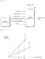
- FIG. 5 is a graph showing the relationship between a voltage and a rotation speed of the motor 140 in controlling the laundry treatment machine 1, according to an embodiment of the present invention.
- a first line L1 shows an unloaded state
- a second line L2 shows a loaded state of water.
- a rotation speed RPM of the motor 140 is increased in proportion to a speed control voltage VSP of the motor controller 120.
- the relationship between the voltage and the rotation speed in the loaded state and the relationship in the unloaded state are compared as described below.
- the rotation speed of the motor 140 measured when water is not loaded i.e., when the level of water is zero
- the rotation speed of the motor 140 measured when water is not loaded is higher compared to that measured when water is present.
- the rotation speed of the motor 140 is increased in proportion to the voltage depending on the load of the water.
- a drain filter if a drain filter is clogged with foreign substances, water may not be normally drained and thus a current for driving the motor 140 may be increased. In addition, it may be determined whether water is normally drained, based on a variation in the rotation speed of the motor 140 measured for a preset drain time.
- the main controller 110 may determine that an error occurs and thus output the error through the output unit 160.
- FIG. 6 is a flowchart of a method for controlling the laundry treatment machine 1, according to an embodiment of the present invention.
- the main controller 110 applies a drain command to the motor controller 120 (S310).
- the motor controller 120 generates a control signal for controlling the motor 140 of the pump 11, and sets a voltage for setting a speed of the motor 140 (S320 and S330).
- the motor driver 130 receives the control signal of the motor controller 120 and supplies driving power to the motor 140, and thus the motor 140 rotates and operates (S340).
- the speed sensor 151 measures the rotation speed of the motor 140 (S360), and applies the measured rotation speed to the main controller 110 and the motor controller 120.
- the motor controller 120 generates a control signal for subsequent control of the motor 140 based on the input rotation speed.
- the main controller 110 determines whether the measured rotation speed of the motor 140 is increased by a certain rate or more (S370). In this case, the main controller 110 determines whether the rotation speed of the motor 140 is increased by 33% or more compared to a pre-measured rotation speed.
- the main controller 110 applies a motor stop command to the motor controller 120 (S400).
- the current sensor 152 measures a current applied from the motor driver 130 to the motor 140 (S380).
- the main controller 110 compares the measured current value to a previous current value, and determines whether the current is reduced (S390). For example, the main controller 110 may determine whether the current is reduced by 90% or more.
- the main controller 110 applies a motor stop command to the motor controller 120 (S400).
- the motor 140 continues operating. While the motor 140 operates, the rotation speed and the current value thereof are sensed and variations therein are monitored.
- the main controller 110 determines whether overcurrent is supplied to the motor 140, a load state, or whether the level of water is zero, based on the variations in the rotation speed and the current.
- the main controller 110 stops the motor 140, counts the number of times that the motor 140 stops, and determines whether the number of times that the motor 140 stops is equal to or greater than a reference number (S410).
- the main controller 110 applies a motor driving command to the motor controller 120 to drive the motor 140 again.
- the main controller 110 controls the water level sensor 156 to measure the level of water (S430).
- the main controller 110 determines whether water is completely drained to a designated level, based on the measured level of water (S450). If water is not completely drained, the motor 140 is driven again to operate the pump 11 again.
- the main controller 110 determines that drainage is completed (S460), and the method proceeds to a subsequent process.
- a load state of water and an error in drainage due to, for example, foreign substances are sensed and overcurrent supplied to a motor is determined depending on variations in rotation speed and current value of the motor.
- operation of the motor is controlled.
- the motor may be protected, may achieve noise reduction, and thus may be controlled more efficiently.
Abstract
Description
- The present invention relates to a laundry treatment machine and a method for controlling the same and, more particularly, to a laundry treatment machine for controlling a motor by sensing a load state based on operation of a pump for drainage and circulation of water, and a method for controlling the laundry treatment machine.
- In general, a laundry treatment machine performs a washing process using friction between laundry and a tub, which rotates by receiving a driving force from a motor, after detergent, water and the laundry are inserted into the tub, and thus can wash the laundry without damaging or tangling the laundry.
- The general laundry treatment machine is configured to supply water into the tub, drain a part of water, supply water again, and then completely drain water as a washing process proceeds.
- To circulate or drain water, the laundry treatment machine includes a pump attached to a drain hose connected to the tub, and the pump includes a motor. As the pump operates due to the motor, water flowing toward a drain is supplied into the tub again through a circulation hose or is drained through the drain hose.
- When the flow of water is controlled as described above, the pump can brake if the pump continues operating after water is completely drained or stops operating while water is not completely drained.
- In addition, if the drain is clogged with foreign substances, water is not normally drained. In this case, since water is not completely drained, the pump continues operating and thus is overloaded due to the abnormal flow of water.
- Accordingly, a method for controlling the pump by sensing a load state of the tub or the drain hose is necessary.
- Therefore, the present invention has been made in view of the above problems, and it is an object of the present invention to provide a laundry treatment machine for sensing a voltage applied to a motor included in a pump for circulation and drainage of water to determine a load state of water inside a tub, and controlling operation of the motor depending on the determined load state, and a method for controlling the laundry treatment machine.
- In accordance with an aspect of the present invention, the above and other objects can be accomplished by the provision of a laundry treatment machine including a motor included in a pump for draining or circulating water, to operate the pump, a motor driver for supplying operation power to the motor, a motor controller for setting a rotation speed of the motor and applying a signal for controlling the motor to the motor driver, a current sensor for measuring a current of the operation power supplied from the motor driver to the motor, a speed sensor for measuring a rotation speed of the motor, a water level sensor for measuring a level of water in a tub, and a main controller for applying a control command to the motor controller to start or stop operation of the motor, wherein the main controller controls the motor to stop by determining a load state of water and determining whether the level of water is zero, based on the current measured by the current sensor and the rotation speed of the motor measured by the speed sensor.
- In accordance with another aspect of the present invention, there is provided a method for controlling a laundry treatment machine, the method including operating a motor of a pump to drain water if a water drain command is applied, measuring a current and a rotation speed of the motor, determining whether the current or the rotation speed varies by a specific reference value or more, stopping the motor if the current or the rotation speed varies by the reference value or more, and driving the motor again to complexly drain water after a specific period of time passes.
- A laundry treatment machine and a method for controlling the same according to embodiments of the present invention achieve the following effect. In operation of a pump for circulating and draining water, since the load of water to be drained is sensed and whether an error occurs due to foreign substances is determined based on a current and a rotation speed of a motor included in the pump, unnecessary operation of the pump may not be performed, damage of the pump due to overload may be prevented, noise due to pump operation in overloaded state may be solved, and the efficiency of pump control may be improved.
-
-
FIG. 1 is a perspective view of a laundry treatment machine according to an embodiment of the present invention; -
FIG. 2 is a schematic diagram showing the configurations of a tub and a pump of the laundry treatment machine, according to an embodiment of the present invention; -
FIG. 3 is a block diagram of the laundry treatment machine according to an embodiment of the present invention; -
FIG. 4 is a schematic diagram showing signal information depending on sensing of the load of the laundry treatment machine, according to an embodiment of the present invention; -
FIG. 5 is a graph showing the relationship between a voltage and a rotation speed of the motor in controlling the laundry treatment machine, according to an embodiment of the present invention; and -
FIG. 6 is a flowchart of a method for controlling the laundry treatment machine, according to an embodiment of the present invention. - Hereinafter, the present invention will be described in detail by explaining embodiments of the invention with reference to the attached drawings. The invention may, however, be embodied in many different forms and should not be construed as being limited to the embodiments set forth herein; rather, these embodiments are provided so that this disclosure will be thorough and complete, and will fully convey the concept of the invention to one of ordinary skill in the art. In the drawings, like reference numerals denote like elements.
- The terms "module" and "unit" used to signify components are used herein to help the understanding of the components and thus should not be construed as having specific meanings or functions. Accordingly, the terms "module" and "unit" may be used interchangeably.
-
FIG. 1 is a perspective view of a laundry treatment machine 1 according to an embodiment of the present invention, andFIG. 2 is a schematic diagram showing the configurations of a tub and apump 11 of the laundry treatment machine 1, according to an embodiment of the present invention. - Referring to
FIGS. 1 and2 , the laundry treatment machine 1 according to an embodiment of the present invention is a top-loading laundry treatment machine in which laundry is inserted into a tub from above. The top-loading laundry treatment machine includes the concept of a washing machine for performing washing, rinsing and spin-drying processes after laundry is inserted, or a drying machine for performing a drying process after wet laundry is inserted, and the following description is focused on the washing machine. - The washing machine 1 includes a casing for forming the exterior of the washing machine 1, manipulation keys for receiving a variety of control commands input by a user, a control panel for providing a user interface using, for example, a display for displaying information about an operation state of the washing machine 1, and a door for opening or closing an opening through which laundry enters or exits.
- The control panel includes an input unit including a plurality of manipulation keys for manipulating an operation state of the laundry treatment machine 1, and a display unit for displaying the operation state of the laundry treatment machine 1.
- The washing machine 1 includes the tub. The tub includes an
outer tub 13 for accommodating water, and aninner tub 12 rotatably provided in theouter tub 13 to accommodate laundry. - The washing machine 1 may include a
pulsator 14 rotatably provided at the bottom of the tub and, more particular, at the bottom of theinner tub 12. - A driving device (not shown) provides a driving force for rotating the
inner tub 12 and/or thepulsator 14. In addition, a clutch (not shown) for selectively delivering the driving force of the driving device may be provided to rotate only theinner tub 12, to rotate only thepulsator 14, or to simultaneously rotate theinner tub 12 and thepulsator 14. - The
inner tub 12 has a plurality of holes (not shown) and thus water supplied into theinner tub 12 flows through the holes to theouter tub 13. A water inlet valve (not shown) for opening or closing a water inlet hose (not shown) may be provided to supply water into the tub. - Water in the
outer tub 13 is drained through adrain hose 15, and a drain valve (not shown) for opening or closing thedrain hose 15, and thepump 11 for pumping water are provided. - In this case, the
pump 11 discharges water through thedrain hose 15 to the outside of the washing machine 1, or supplies water through acirculation hose 16 into the tub again, depending on a rotation direction thereof. - A
spray nozzle 17 may be provided at an end of thecirculation hose 16 and thus the circulated and re-supplied water may be sprayed. - When water is supplied into the tub through the water inlet hose, a water level sensor (not shown) senses the level of water. In this case, if water is supplied to a
first point 18, the level of water corresponds to a height from the location of thedrain hose 15 to thefirst point 18 and alevel 19 is measured. -
FIG. 3 is a block diagram of the laundry treatment machine 1 according to an embodiment of the present invention. - The washing machine 1 includes an
input unit 170, anoutput unit 160, awater level sensor 156, acurrent sensor 152, amotor controller 120, amotor driver 130, amotor 140, aspeed sensor 151, adriving controller 180, adriving device 190, and amain controller 110 for providing overall control to the washing machine 1. The washing machine 1 may further include a storage (not shown) for storing data. - In this case, the
motor 140 is a motor of the pump 1 mounted on thedrain hose 15 for drainage and circulation of water, and themotor controller 120 and themotor driver 130 are used to control operation of themotor 140 of thepump 11. Although the washing machine 1 further includes a plurality of sensors and additional devices related to thedriving device 190, and other elements such as a water inlet valve and a drain valve, descriptions thereof are omitted herein and the following description is focused on a configuration for controlling thepump 11. - As an input means including the
input unit 170 is manipulated, a specific signal is input to themain controller 110. Theinput unit 170 includes a plurality of manipulation keys provided on the control panel, and may further include a specific input means such as a touchpad. - The
input unit 170 inputs setting data such as a washing mode, a washing temperature, a water level, or a reservation time, and inputs a control command for starting or stopping operation of the washing machine 1 depending on the setting data. - The
output unit 160 outputs the setting data input through theinput unit 170, e.g., the washing mode, the washing temperature, or the water level, and outputs process information such as a current washing process state and a remaining washing time. - The
output unit 160 includes a display means for displaying the setting data or the process information in the form of text, a number, or an image. In addition, theoutput unit 160 may include a buzzer (not shown) or a speaker (not shown) for outputting a specific sound effect or an alarm, and a lamp (not shown) to be turned on or off to output an operation state or a warning. - The storage stores basic data for controlling operation of the washing machine 1, control data for controlling the operation, input and output data, and data input from a plurality of sensors while the washing machine 1 operates.
- The
driving controller 180 controls thedriving device 190 to rotate based on a control command of themain controller 110. Thedriving device 190 includes another motor which rotates under control of thedriving controller 180. Thedriving device 190 rotates at least one of thepulsator 14 or theinner tub 12. - The
water level sensor 156 includes at least one sensor and measures thewater level 19 in the tub. As described above, if water is supplied to thefirst point 18, thewater level 19 is measured and provided to themain controller 110 and themotor controller 120. - The
motor controller 120 generates a control signal for driving themotor 140 to operate thepump 11 depending on a control command of themain controller 110. The control signal generated in this case is a switching control signal, e.g., a pulse width modulation (PWM) signal. - In addition, the
motor controller 120 generates a revolutions per minute (RPM) signal for controlling a rotation speed of themotor 140, as a control signal depending on a sensed load state of water. This signal sets a target rotation speed of themotor 140 and is variable depending on the load state of water. - In this case, the
motor controller 120 outputs the PWM signal through a resistor-capacitor (RC) filter in such a manner that the PWM signal is input to themotor driver 130, and the RPM signal corresponds to a speed control voltage VSP, is set within a range from direct-current (DC) 1V to 4V, and is input to themotor driver 130. - The
motor driver 130 supplies a current having a specific magnitude as motor driving power to themotor 140 based on the control signals input from themotor controller 120, i.e., the PWM signal and the RPM signal. In this case, themotor driver 130 includes a sensorless integrated circuit (IC) and a protection circuit. - As such, the
motor 140 rotates and water of thedrain hose 15 is drained or circulated and supplied into the tub again. - The
motor 140 is a motor included in thepump 11 as described above. In this case, themotor 140 is a brushless DC (BLDC) motor. - The
motor 140 rotates clockwise or counterclockwise under control of themotor controller 120 and themotor driver 130, and thus thepump 11 drains or circulates water. - For example, water is drained if the
motor 140 rotates clockwise, and is circulated and supplied through thecirculation hose 16 into the tub again if themotor 140 rotates counterclockwise. - The
current sensor 152 measures the current supplied from themotor driver 130 to themotor 140 and inputs the same to themotor controller 120. In addition, thecurrent sensor 152 inputs the sensed current to themain controller 110. Thecurrent sensor 152 includes an amplifier. - The
speed sensor 151 measures a rotation speed of themotor 140 and inputs the same to themotor controller 120. In this case, thespeed sensor 151 measures the speed by receiving a voltage of themotor 140, and a comparative value between a DC link voltage and a distribution value, and calculates RPM corresponding to the voltage. - In addition, the
speed sensor 151 inputs the rotation speed of themotor 140 to themain controller 110. - The
main controller 110 controls input and output of data to and from theinput unit 170 and theoutput unit 160, and controls the data to be stored in the storage. Themain controller 110 sets operation of the washing machine 1 based on the setting data input through theinput unit 170, and thus controls the washing machine 1 to operate. As such, the washing machine 1 performs a washing process, a rinsing process, and a spin-drying process. A washer & dryer may further perform a drying process. Themain controller 110 controls the display of theoutput unit 160 to display a washing mode, a washing time, a spin-drying time, a rinsing time, or a current operation state. - When the washing machine 1 operates and starts to wash laundry, the
main controller 110 controls the drain valve not to drain water and controls the water inlet valve to supply water into the tub. - The
main controller 110 controls thepump 11 to operate while the washing process or the rinsing process is performed, in such a manner that water is supplied through thecirculation hose 16 into the tub again, and applies a control command to themotor controller 120 to drain water when the washing process and the rinsing process are completed. - In this case, the
motor controller 120 generates a control signal for operation of thepump 11 depending on the control command of themain controller 110, and applies the same to themotor driver 130, and themotor driver 130 supplies motor driving power to themotor 140 to operate thepump 11. - The
main controller 110 receives the current of themotor 140 of thepump 11 from thecurrent sensor 152, receives the rotation speed of themotor 140 from thespeed sensor 151, and determines whether the level of water in the tub is zero based on the current and the rotation speed. In this case, the current input from thecurrent sensor 152 and to themain controller 110 is a value converted by an analog to digital converter (ADC), and the rotation speed input from thespeed sensor 151 to themain controller 110 is a speed signal timer-processed by an encoder. - In addition, the
main controller 110 determines whether overcurrent occurs and determines the load of water, based on the current and the rotation speed of themotor 140. - The
main controller 110 inputs the results of determining whether the level of water is zero, whether overcurrent occurs, and the load, to themotor controller 120. As such, themotor controller 120 receives a zero water level signal, an overcurrent signal, and load data from themain controller 110, and reflects the same in a control signal for controlling themotor 140 of thepump 11. - In this case, when a set process is performed, if the
pump 11 operates for drainage or circulation of water, themain controller 110 applies a control command to themotor controller 120 to control thepump 11 to start operation depending on the water level of thewater level sensor 156. Furthermore, themain controller 110 applies a control command to themotor controller 120 to control thepump 11 to stop operation depending on whether the level of water is zero, while thepump 11 operates. - In addition, the
main controller 110 determines whether the washing machine 1 normally operates, based on data input from a plurality of sensors, and outputs an error through theoutput unit 160 if an error occurs. -
FIG. 4 is a schematic diagram showing signal information depending on sensing of the load of the laundry treatment machine 1, according to an embodiment of the present invention. - Referring to
FIG. 4 , themain controller 110 determines whether the level of water is zero, determines whether overcurrent occurs, and determines the load of water, based on the current of themotor 140, which is input from thecurrent sensor 152, and the rotation speed (e.g., RPM) of themotor 140, which is input from thespeed sensor 151. - The
main controller 110 may determine that the level of water is zero, if the input rotation speed is increased and the current is reduced, according to a load sensing algorithm. In this case, themain controller 110 determines whether water is drained and the level of water is zero, in further consideration of the water level input from thewater level sensor 156. - Based on the input rotation speed of the
motor 140 of thepump 11 and the current, themain controller 110 determines the load of water and determines whether overcurrent occurs, if the rotation speed of themotor 140 of thepump 11 is reduced and the current is increased. - Depending on the determination result of the
main controller 110, a zero water level signal, an overcurrent signal, and a load signal are input to themotor controller 120, and the current of thecurrent sensor 152, the rotation speed of the speed sensor 151 (e.g., a currently measured RPM), and the water level of thewater level sensor 156 are input to themotor controller 120. In addition, a target RPM of themotor 140 for driving thepump 11 is input from themain controller 110 to themotor controller 120. - The
motor controller 120 generates a PWM signal based on the input data, sets a rotation speed of themotor 140, and inputs the rotation speed to themotor driver 130, and themotor driver 130 supplies driving power based thereon to themotor 140. Thecurrent sensor 152 senses and inputs an output current input from themotor driver 130 to themotor 140, to themotor controller 120 and themain controller 110, and measures and inputs a rotation speed of thespeed sensor 151 to themotor controller 120 and themain controller 110 if themotor 140 operates. - As such, the
motor controller 120 varies control of themotor 140 based on the target RPM, the actually measured RPM, and the current value in consideration of the load state of water, whether the level of water is zero, and whether overcurrent occurs. - In addition, the
main controller 110 applies a control command to themotor controller 120 to stop or restart operation of themotor 140 based on the load state of water, whether the level of water is zero, whether overcurrent occurs, and variations in current value and rotation speed. -
FIG. 5 is a graph showing the relationship between a voltage and a rotation speed of themotor 140 in controlling the laundry treatment machine 1, according to an embodiment of the present invention. In this case, a first line L1 shows an unloaded state, and a second line L2 shows a loaded state of water. - As illustrated in
FIG. 5 , a rotation speed RPM of themotor 140 is increased in proportion to a speed control voltage VSP of themotor controller 120. - In addition, when water is present in the tub, the relationship between the voltage and the rotation speed in the loaded state and the relationship in the unloaded state (i.e., zero water level) are compared as described below. At the same speed control voltage, the rotation speed of the
motor 140 measured when water is not loaded (i.e., when the level of water is zero) is higher compared to that measured when water is present. - If cases of a first voltage V1 and a second voltage V2 are compared, the rotation speed of the
motor 140 is increased in proportion to the voltage depending on the load of the water. - Accordingly, if a timing when water starts to be drained, a timing when the level of water is a half of an initial water level, and a timing when water is completely drained and thus the level of water is zero water are compared, the rotation speed of the
motor 140 of thepump 11 is increased as the load of water is reduced. - In this case, if a drain filter is clogged with foreign substances, water may not be normally drained and thus a current for driving the
motor 140 may be increased. In addition, it may be determined whether water is normally drained, based on a variation in the rotation speed of themotor 140 measured for a preset drain time. - As such, the
main controller 110 may determine that an error occurs and thus output the error through theoutput unit 160. -
FIG. 6 is a flowchart of a method for controlling the laundry treatment machine 1, according to an embodiment of the present invention. - If the washing machine 1 starts operation depending on setting data and drains water in a washing process or a rinsing process, the
main controller 110 applies a drain command to the motor controller 120 (S310). - The
motor controller 120 generates a control signal for controlling themotor 140 of thepump 11, and sets a voltage for setting a speed of the motor 140 (S320 and S330). - The
motor driver 130 receives the control signal of themotor controller 120 and supplies driving power to themotor 140, and thus themotor 140 rotates and operates (S340). - In this case, the
speed sensor 151 measures the rotation speed of the motor 140 (S360), and applies the measured rotation speed to themain controller 110 and themotor controller 120. Themotor controller 120 generates a control signal for subsequent control of themotor 140 based on the input rotation speed. - The
main controller 110 determines whether the measured rotation speed of themotor 140 is increased by a certain rate or more (S370). In this case, themain controller 110 determines whether the rotation speed of themotor 140 is increased by 33% or more compared to a pre-measured rotation speed. - If the rotation speed of the
motor 140 is increased by the certain rate or more, themain controller 110 applies a motor stop command to the motor controller 120 (S400). - Meanwhile, the
current sensor 152 measures a current applied from themotor driver 130 to the motor 140 (S380). - The
main controller 110 compares the measured current value to a previous current value, and determines whether the current is reduced (S390). For example, themain controller 110 may determine whether the current is reduced by 90% or more. - If the current is reduced by a certain value or more, the
main controller 110 applies a motor stop command to the motor controller 120 (S400). - Otherwise, if the current is not reduced or is reduced by a value less than the certain value, or if the speed is not increased or is increased by a rate less than the certain rate, the
motor 140 continues operating. While themotor 140 operates, the rotation speed and the current value thereof are sensed and variations therein are monitored. - As such, the
main controller 110 determines whether overcurrent is supplied to themotor 140, a load state, or whether the level of water is zero, based on the variations in the rotation speed and the current. - The
main controller 110 stops themotor 140, counts the number of times that themotor 140 stops, and determines whether the number of times that themotor 140 stops is equal to or greater than a reference number (S410). - If the number of times that the
motor 140 stops is less than the reference number, after a specific period of time passes (S420), themain controller 110 applies a motor driving command to themotor controller 120 to drive themotor 140 again. - Otherwise, if the number of times that the
motor 140 stops is equal to or greater than the reference number, themain controller 110 controls thewater level sensor 156 to measure the level of water (S430). - The
main controller 110 determines whether water is completely drained to a designated level, based on the measured level of water (S450). If water is not completely drained, themotor 140 is driven again to operate thepump 11 again. - If water is completely drained, the
main controller 110 determines that drainage is completed (S460), and the method proceeds to a subsequent process. - Therefore, according to the present invention, a load state of water and an error in drainage due to, for example, foreign substances are sensed and overcurrent supplied to a motor is determined depending on variations in rotation speed and current value of the motor. Thus, operation of the motor is controlled. As such, the motor may be protected, may achieve noise reduction, and thus may be controlled more efficiently.
- Although all elements constituting the embodiments of the present invention are described to be integrated into a single one or to be operated as a single one, the present invention is not necessarily limited to such embodiments. According to embodiments, all of the elements may be selectively integrated into one or more and be operated as one or more within the object and the scope of the present invention
- The preferred embodiments of the present invention have been disclosed for illustrative purposes, those skilled in the art will appreciate that various modifications, additions and substitutions are possible, without departing from the scope and spirit of the invention as disclosed in the accompanying claims.
Claims (15)
- A laundry treatment machine comprising:a motor comprised in a pump for draining or circulating water, to operate the pump;a motor driver for supplying operation power to the motor;a motor controller for setting a rotation speed of the motor and applying a signal for controlling the motor to the motor driver;a current sensor for measuring a current of the operation power supplied from the motor driver to the motor;a speed sensor for measuring a rotation speed of the motor;a water level sensor for measuring a level of water in a tub; anda main controller for applying a control command to the motor controller to start or stop operation of the motor,wherein the main controller controls the motor to stop by determining a load state of water and determining whether the level of water is zero, based on the current measured by the current sensor and the rotation speed of the motor measured by the speed sensor.
- The laundry treatment machine according to claim 1, wherein the motor controller stops the motor if a zero water level sensing signal or an overcurrent sensing signal is input from the main controller.
- The laundry treatment machine according to claim 1, wherein the main controller determines whether overcurrent occurs or determines the load state, if the rotation speed of the motor is reduced and the current is increased.
- The laundry treatment machine according to claim 1, wherein the main controller determines whether the level of water is zero, if the rotation speed is increased and the current is reduced.
- The laundry treatment machine according to claim 1, wherein the main controller controls the motor to stop, if the rotation speed is increased by a certain rate or more.
- The laundry treatment machine according to claim 5, wherein the main controller controls the motor to stop, if the rotation speed is increased by 33% or more.
- The laundry treatment machine according to claim 1, wherein the main controller controls the motor to stop, if the current is reduced by a certain value or more.
- The laundry treatment machine according to claim 7, wherein the main controller controls the motor to stop, if the current is reduced by 90% or more.
- The laundry treatment machine according to claim 1, wherein the main controller counts a number of times that the motor stops, and determines whether water is completely drained, based on the level of water measured by the water level sensor, if the number of times that the motor stops is equal to or greater than a reference number.
- The laundry treatment machine according to claim 1, wherein the main controller counts a number of times that the motor stops, and controls the motor to stop and then to be driven again after a specific period of time, if the number of times that the motor stops is less than a reference number.
- A method for controlling a laundry treatment machine, the method comprising:operating a motor of a pump to drain water if a water drain command is applied;measuring a current and a rotation speed of the motor;determining whether the current or the rotation speed varies by a specific reference value or more;stopping the motor if the current or the rotation speed varies by the reference value or more; anddriving the motor again to complexly drain water after a specific period of time passes.
- The method according to claim 11, wherein the determining comprises determining whether the current is reduced by 90% or more compared to a pre-measured current.
- The method according to claim 11, wherein the determining comprises determining whether the rotation speed is increased by 33% or more compared to a pre-measured rotation speed.
- The method according to claim 11, further comprising counting a number of times that the motor stops, when the motor stops,
wherein the motor is driven again after a specific period of time passes, if the number of times that the motor stops is less than a reference number. - The method according to claim 14, further comprising:sensing a level of water if the number of times that the motor stops is equal to or greater than the reference number; anddriving the motor again if water is not complexly drained.
Applications Claiming Priority (2)
| Application Number | Priority Date | Filing Date | Title |
|---|---|---|---|
| KR1020140146384A KR102196183B1 (en) | 2014-10-27 | 2014-10-27 | laundry treatment machine and method for contorolling the same |
| PCT/KR2015/011376 WO2016068575A1 (en) | 2014-10-27 | 2015-10-27 | Laundry treating apparatus and control method thereof |
Publications (2)
| Publication Number | Publication Date |
|---|---|
| EP3214218A1 true EP3214218A1 (en) | 2017-09-06 |
| EP3214218A4 EP3214218A4 (en) | 2018-07-18 |
Family
ID=55791534
Family Applications (1)
| Application Number | Title | Priority Date | Filing Date |
|---|---|---|---|
| EP15855184.6A Pending EP3214218A4 (en) | 2014-10-27 | 2015-10-27 | Laundry treating apparatus and control method thereof |
Country Status (5)
| Country | Link |
|---|---|
| US (1) | US9863077B2 (en) |
| EP (1) | EP3214218A4 (en) |
| KR (1) | KR102196183B1 (en) |
| CN (1) | CN107109762B (en) |
| WO (1) | WO2016068575A1 (en) |
Families Citing this family (14)
| Publication number | Priority date | Publication date | Assignee | Title |
|---|---|---|---|---|
| CN206204637U (en) * | 2016-07-20 | 2017-05-31 | 青岛海尔洗衣机有限公司 | A kind of device for reducing condensing tumble drier drainage noise |
| KR102627102B1 (en) | 2017-01-11 | 2024-01-22 | 엘지전자 주식회사 | Laundry treating appratus and controlling method thereof |
| KR102418952B1 (en) * | 2017-08-31 | 2022-07-08 | 삼성전자주식회사 | Home appliance having voice recognizing function |
| CN109487502B (en) * | 2017-09-13 | 2022-09-06 | 青岛海尔洗涤电器有限公司 | Control method for midway drainage of laundry equipment and laundry equipment |
| KR102544919B1 (en) * | 2018-04-06 | 2023-06-16 | 엘지전자 주식회사 | Laundry Treating Apparatus and Method thereof |
| KR102056168B1 (en) * | 2018-04-19 | 2019-12-16 | 엘지전자 주식회사 | Laundry treatment machine |
| KR102603619B1 (en) * | 2018-07-06 | 2023-11-16 | 엘지전자 주식회사 | Drain pump driving apparatus and laundry treatment machine including the same |
| KR102627647B1 (en) * | 2019-01-21 | 2024-01-19 | 엘지전자 주식회사 | Laundry treatment machine |
| CN111850948B (en) * | 2019-04-17 | 2022-11-15 | 重庆海尔洗衣机有限公司 | Control method of washing machine water pump and washing machine water pump |
| CN111431441B (en) * | 2020-04-10 | 2022-01-11 | 宁波奥克斯电气股份有限公司 | Motor rotating speed control method and device, air conditioner and storage medium |
| CN112853676A (en) * | 2020-12-31 | 2021-05-28 | 长虹美菱股份有限公司 | Dewatering control method for active noise reduction of draining pump |
| EP4075663A1 (en) * | 2021-04-15 | 2022-10-19 | Vestel Elektronik Sanayi ve Ticaret A.S. | Motor controller, washing machine and method |
| CN114158995B (en) * | 2021-11-09 | 2024-03-19 | 佛山市百斯特电器科技有限公司 | Fault identification method and washing equipment |
| KR20230118336A (en) * | 2022-02-04 | 2023-08-11 | 엘지전자 주식회사 | A laundry treating apparatus |
Family Cites Families (11)
| Publication number | Priority date | Publication date | Assignee | Title |
|---|---|---|---|---|
| KR960037945A (en) * | 1995-04-29 | 1996-11-19 | 배순훈 | How to detect drainage abnormalities in the washing machine |
| KR970027459A (en) * | 1995-11-30 | 1997-06-24 | 배순훈 | Drain pump control method of washing machine |
| KR100280605B1 (en) * | 1998-12-29 | 2001-02-01 | 구자홍 | How to drain the washing water when the water supply valve of the drum washing machine is broken |
| US7810362B2 (en) * | 2005-11-04 | 2010-10-12 | Fisher & Paykel Appliances Ltd. | Recirculation control in a washing machine |
| KR100889817B1 (en) * | 2007-04-03 | 2009-03-20 | 삼성전자주식회사 | Washing machine and controllig method of the same of |
| KR100891912B1 (en) * | 2007-09-04 | 2009-04-08 | 엘지전자 주식회사 | Control method of a laundry treatment machine |
| JP5489328B2 (en) * | 2009-08-24 | 2014-05-14 | 株式会社東芝 | Drum washing machine |
| CN102482833B (en) * | 2009-08-24 | 2014-07-30 | 株式会社东芝 | Drum type washing machine |
| JP2011250848A (en) * | 2010-05-31 | 2011-12-15 | Sharp Corp | Washing machine |
| US20120005840A1 (en) * | 2010-07-06 | 2012-01-12 | Jang Hoyong | Washing machine and method for controlling the same |
| WO2013073140A1 (en) * | 2011-11-14 | 2013-05-23 | パナソニック株式会社 | Drum-type washing machine |
-
2014
- 2014-10-27 KR KR1020140146384A patent/KR102196183B1/en active IP Right Grant
-
2015
- 2015-10-27 CN CN201580071026.8A patent/CN107109762B/en active Active
- 2015-10-27 US US14/923,827 patent/US9863077B2/en active Active
- 2015-10-27 WO PCT/KR2015/011376 patent/WO2016068575A1/en active Application Filing
- 2015-10-27 EP EP15855184.6A patent/EP3214218A4/en active Pending
Also Published As
| Publication number | Publication date |
|---|---|
| CN107109762A (en) | 2017-08-29 |
| KR20160049367A (en) | 2016-05-09 |
| US9863077B2 (en) | 2018-01-09 |
| US20160115632A1 (en) | 2016-04-28 |
| WO2016068575A1 (en) | 2016-05-06 |
| CN107109762B (en) | 2020-05-12 |
| KR102196183B1 (en) | 2020-12-29 |
| EP3214218A4 (en) | 2018-07-18 |
Similar Documents
| Publication | Publication Date | Title |
|---|---|---|
| US9863077B2 (en) | Laundry treatment machine | |
| TWI261638B (en) | Washing machine | |
| US10934657B2 (en) | Washer dryer machine and control method | |
| US11326297B2 (en) | Washing machine with heater and multiple tubs and control method thereof | |
| EP2848726B1 (en) | A method for operating a washing machine | |
| CN107558101A (en) | A kind of dehydration controlling method, dehydration control apparatus and washing machine | |
| US20160194803A1 (en) | A Method for Operating a Washing Machine During a Washing Cycle | |
| CN108697297A (en) | Processing in circulating pump is detected with water flow | |
| US9752268B2 (en) | Control method of washing machine | |
| US11846060B2 (en) | Laundry treatment apparatus and control method thereof | |
| CN112912555B (en) | Washing machine | |
| KR102476288B1 (en) | Laundry Treating Apparatus and Method thereof | |
| JP2019025136A (en) | Washing machine | |
| JP4656661B2 (en) | Washing machine | |
| KR20150041855A (en) | Washing apparatus and controlling method thereof | |
| JP2005143531A (en) | Washing machine | |
| JP2020081459A (en) | Washing machine | |
| KR100712848B1 (en) | Control method of washing machine | |
| KR101585449B1 (en) | Method of controlling washing machine | |
| KR102437907B1 (en) | Laundry Treating Apparatus and Method thereof | |
| JP2017080087A (en) | Washing machine | |
| KR20230103589A (en) | Washing machine and controlling method thereof | |
| JP2007082653A (en) | Washer and washer-dryer | |
| KR20150118429A (en) | Washing apparatus and controlling method thereof | |
| JP2016054848A (en) | Dishwasher |
Legal Events
| Date | Code | Title | Description |
|---|---|---|---|
| STAA | Information on the status of an ep patent application or granted ep patent |
Free format text: STATUS: THE INTERNATIONAL PUBLICATION HAS BEEN MADE |
|
| PUAI | Public reference made under article 153(3) epc to a published international application that has entered the european phase |
Free format text: ORIGINAL CODE: 0009012 |
|
| STAA | Information on the status of an ep patent application or granted ep patent |
Free format text: STATUS: REQUEST FOR EXAMINATION WAS MADE |
|
| 17P | Request for examination filed |
Effective date: 20170526 |
|
| AK | Designated contracting states |
Kind code of ref document: A1 Designated state(s): AL AT BE BG CH CY CZ DE DK EE ES FI FR GB GR HR HU IE IS IT LI LT LU LV MC MK MT NL NO PL PT RO RS SE SI SK SM TR |
|
| AX | Request for extension of the european patent |
Extension state: BA ME |
|
| DAV | Request for validation of the european patent (deleted) | ||
| DAX | Request for extension of the european patent (deleted) | ||
| A4 | Supplementary search report drawn up and despatched |
Effective date: 20180619 |
|
| RIC1 | Information provided on ipc code assigned before grant |
Ipc: D06F 39/08 20060101ALN20180611BHEP Ipc: D06F 33/02 20060101AFI20180611BHEP Ipc: H02P 29/02 20160101ALI20180611BHEP Ipc: H02P 1/16 20060101ALN20180611BHEP Ipc: H02P 3/06 20060101ALN20180611BHEP |
|
| STAA | Information on the status of an ep patent application or granted ep patent |
Free format text: STATUS: EXAMINATION IS IN PROGRESS |
|
| 17Q | First examination report despatched |
Effective date: 20210617 |
|
| STAA | Information on the status of an ep patent application or granted ep patent |
Free format text: STATUS: EXAMINATION IS IN PROGRESS |
|
| REG | Reference to a national code |
Ref country code: DE Ref legal event code: R079 Free format text: PREVIOUS MAIN CLASS: D06F0039080000 Ipc: H02P0029020000 |
|
| GRAP | Despatch of communication of intention to grant a patent |
Free format text: ORIGINAL CODE: EPIDOSNIGR1 |
|
| STAA | Information on the status of an ep patent application or granted ep patent |
Free format text: STATUS: GRANT OF PATENT IS INTENDED |