EP3214042A1 - Layered double hydroxide-containing composite material - Google Patents
Layered double hydroxide-containing composite material Download PDFInfo
- Publication number
- EP3214042A1 EP3214042A1 EP15854191.2A EP15854191A EP3214042A1 EP 3214042 A1 EP3214042 A1 EP 3214042A1 EP 15854191 A EP15854191 A EP 15854191A EP 3214042 A1 EP3214042 A1 EP 3214042A1
- Authority
- EP
- European Patent Office
- Prior art keywords
- porous substrate
- functional layer
- ldh
- composite material
- hydroxide
- Prior art date
- Legal status (The legal status is an assumption and is not a legal conclusion. Google has not performed a legal analysis and makes no representation as to the accuracy of the status listed.)
- Granted
Links
- 239000002131 composite material Substances 0.000 title claims abstract description 75
- XLYOFNOQVPJJNP-UHFFFAOYSA-M hydroxide Chemical compound [OH-] XLYOFNOQVPJJNP-UHFFFAOYSA-M 0.000 title claims abstract description 28
- 239000000758 substrate Substances 0.000 claims abstract description 216
- 239000002346 layers by function Substances 0.000 claims abstract description 120
- NINIDFKCEFEMDL-UHFFFAOYSA-N Sulfur Chemical compound [S] NINIDFKCEFEMDL-UHFFFAOYSA-N 0.000 claims abstract description 18
- 229910052717 sulfur Inorganic materials 0.000 claims abstract description 18
- 239000011593 sulfur Substances 0.000 claims abstract description 18
- 150000001768 cations Chemical class 0.000 claims abstract description 13
- 150000001450 anions Chemical class 0.000 claims abstract description 8
- XLYOFNOQVPJJNP-UHFFFAOYSA-N water Substances O XLYOFNOQVPJJNP-UHFFFAOYSA-N 0.000 claims description 52
- 229910052799 carbon Inorganic materials 0.000 claims description 46
- OKTJSMMVPCPJKN-UHFFFAOYSA-N Carbon Chemical compound [C] OKTJSMMVPCPJKN-UHFFFAOYSA-N 0.000 claims description 45
- 239000002245 particle Substances 0.000 claims description 30
- 241000276425 Xiphophorus maculatus Species 0.000 claims description 23
- MCMNRKCIXSYSNV-UHFFFAOYSA-N Zirconium dioxide Chemical compound O=[Zr]=O MCMNRKCIXSYSNV-UHFFFAOYSA-N 0.000 claims description 20
- 239000000919 ceramic Substances 0.000 claims description 18
- 239000011148 porous material Substances 0.000 claims description 18
- 229920000642 polymer Polymers 0.000 claims description 15
- JLVVSXFLKOJNIY-UHFFFAOYSA-N Magnesium ion Chemical compound [Mg+2] JLVVSXFLKOJNIY-UHFFFAOYSA-N 0.000 claims description 14
- 229910001425 magnesium ion Inorganic materials 0.000 claims description 14
- PNEYBMLMFCGWSK-UHFFFAOYSA-N aluminium oxide Inorganic materials [O-2].[O-2].[O-2].[Al+3].[Al+3] PNEYBMLMFCGWSK-UHFFFAOYSA-N 0.000 claims description 13
- GWEVSGVZZGPLCZ-UHFFFAOYSA-N Titan oxide Chemical compound O=[Ti]=O GWEVSGVZZGPLCZ-UHFFFAOYSA-N 0.000 claims description 12
- CPLXHLVBOLITMK-UHFFFAOYSA-N Magnesium oxide Chemical compound [Mg]=O CPLXHLVBOLITMK-UHFFFAOYSA-N 0.000 claims description 6
- XLOMVQKBTHCTTD-UHFFFAOYSA-N Zinc monoxide Chemical compound [Zn]=O XLOMVQKBTHCTTD-UHFFFAOYSA-N 0.000 claims description 6
- 229910052751 metal Inorganic materials 0.000 claims description 5
- 239000002184 metal Substances 0.000 claims description 5
- 150000002739 metals Chemical class 0.000 claims description 4
- ODINCKMPIJJUCX-UHFFFAOYSA-N Calcium oxide Chemical compound [Ca]=O ODINCKMPIJJUCX-UHFFFAOYSA-N 0.000 claims description 3
- 229910021536 Zeolite Inorganic materials 0.000 claims description 3
- 239000000292 calcium oxide Substances 0.000 claims description 3
- 235000012255 calcium oxide Nutrition 0.000 claims description 3
- 229910052878 cordierite Inorganic materials 0.000 claims description 3
- JSKIRARMQDRGJZ-UHFFFAOYSA-N dimagnesium dioxido-bis[(1-oxido-3-oxo-2,4,6,8,9-pentaoxa-1,3-disila-5,7-dialuminabicyclo[3.3.1]nonan-7-yl)oxy]silane Chemical compound [Mg++].[Mg++].[O-][Si]([O-])(O[Al]1O[Al]2O[Si](=O)O[Si]([O-])(O1)O2)O[Al]1O[Al]2O[Si](=O)O[Si]([O-])(O1)O2 JSKIRARMQDRGJZ-UHFFFAOYSA-N 0.000 claims description 3
- HNPSIPDUKPIQMN-UHFFFAOYSA-N dioxosilane;oxo(oxoalumanyloxy)alumane Chemical compound O=[Si]=O.O=[Al]O[Al]=O HNPSIPDUKPIQMN-UHFFFAOYSA-N 0.000 claims description 3
- KZHJGOXRZJKJNY-UHFFFAOYSA-N dioxosilane;oxo(oxoalumanyloxy)alumane Chemical compound O=[Si]=O.O=[Si]=O.O=[Al]O[Al]=O.O=[Al]O[Al]=O.O=[Al]O[Al]=O KZHJGOXRZJKJNY-UHFFFAOYSA-N 0.000 claims description 3
- 239000000395 magnesium oxide Substances 0.000 claims description 3
- 229910052863 mullite Inorganic materials 0.000 claims description 3
- HBMJWWWQQXIZIP-UHFFFAOYSA-N silicon carbide Chemical compound [Si+]#[C-] HBMJWWWQQXIZIP-UHFFFAOYSA-N 0.000 claims description 3
- 229910010271 silicon carbide Inorganic materials 0.000 claims description 3
- 229910052596 spinel Inorganic materials 0.000 claims description 3
- 239000011029 spinel Substances 0.000 claims description 3
- 239000010457 zeolite Substances 0.000 claims description 3
- 239000011787 zinc oxide Substances 0.000 claims description 3
- 229910000859 α-Fe Inorganic materials 0.000 claims description 3
- 238000005054 agglomeration Methods 0.000 claims description 2
- 230000002776 aggregation Effects 0.000 claims description 2
- 239000012528 membrane Substances 0.000 description 112
- 238000011156 evaluation Methods 0.000 description 43
- 239000011550 stock solution Substances 0.000 description 22
- 239000007789 gas Substances 0.000 description 18
- -1 hydroxide ions Chemical class 0.000 description 18
- 239000000243 solution Substances 0.000 description 17
- 238000004458 analytical method Methods 0.000 description 16
- 125000004429 atom Chemical group 0.000 description 16
- 229920005989 resin Polymers 0.000 description 16
- 239000011347 resin Substances 0.000 description 16
- 239000010410 layer Substances 0.000 description 15
- 238000000034 method Methods 0.000 description 15
- NIXOWILDQLNWCW-UHFFFAOYSA-N acrylic acid group Chemical group C(C=C)(=O)O NIXOWILDQLNWCW-UHFFFAOYSA-N 0.000 description 13
- 238000000151 deposition Methods 0.000 description 13
- 238000010335 hydrothermal treatment Methods 0.000 description 13
- XSQUKJJJFZCRTK-UHFFFAOYSA-N Urea Chemical class NC(N)=O XSQUKJJJFZCRTK-UHFFFAOYSA-N 0.000 description 12
- 230000008021 deposition Effects 0.000 description 12
- 239000004202 carbamide Substances 0.000 description 11
- 229920000307 polymer substrate Polymers 0.000 description 11
- 239000004793 Polystyrene Substances 0.000 description 9
- 229920002223 polystyrene Polymers 0.000 description 9
- 239000000843 powder Substances 0.000 description 9
- 238000006277 sulfonation reaction Methods 0.000 description 9
- 230000015572 biosynthetic process Effects 0.000 description 8
- 239000008151 electrolyte solution Substances 0.000 description 8
- 238000005342 ion exchange Methods 0.000 description 8
- 238000001878 scanning electron micrograph Methods 0.000 description 8
- 238000012360 testing method Methods 0.000 description 8
- 229910002080 8 mol% Y2O3 fully stabilized ZrO2 Inorganic materials 0.000 description 7
- QAOWNCQODCNURD-UHFFFAOYSA-N Sulfuric acid Chemical compound OS(O)(=O)=O QAOWNCQODCNURD-UHFFFAOYSA-N 0.000 description 7
- 230000035699 permeability Effects 0.000 description 7
- 238000004528 spin coating Methods 0.000 description 7
- 229910052782 aluminium Inorganic materials 0.000 description 6
- 239000001307 helium Substances 0.000 description 6
- 229910052734 helium Inorganic materials 0.000 description 6
- SWQJXJOGLNCZEY-UHFFFAOYSA-N helium atom Chemical compound [He] SWQJXJOGLNCZEY-UHFFFAOYSA-N 0.000 description 6
- 239000007784 solid electrolyte Substances 0.000 description 6
- 229910002651 NO3 Inorganic materials 0.000 description 5
- 210000004027 cell Anatomy 0.000 description 5
- 239000011248 coating agent Substances 0.000 description 5
- 238000000576 coating method Methods 0.000 description 5
- 229910001701 hydrotalcite Inorganic materials 0.000 description 5
- 229960001545 hydrotalcite Drugs 0.000 description 5
- 239000000463 material Substances 0.000 description 5
- 229920001343 polytetrafluoroethylene Polymers 0.000 description 5
- 238000002791 soaking Methods 0.000 description 5
- CURLTUGMZLYLDI-UHFFFAOYSA-N Carbon dioxide Chemical compound O=C=O CURLTUGMZLYLDI-UHFFFAOYSA-N 0.000 description 4
- 238000002441 X-ray diffraction Methods 0.000 description 4
- HCHKCACWOHOZIP-UHFFFAOYSA-N Zinc Chemical compound [Zn] HCHKCACWOHOZIP-UHFFFAOYSA-N 0.000 description 4
- 239000013078 crystal Substances 0.000 description 4
- 239000003822 epoxy resin Substances 0.000 description 4
- 238000000349 field-emission scanning electron micrograph Methods 0.000 description 4
- 238000000445 field-emission scanning electron microscopy Methods 0.000 description 4
- MFUVDXOKPBAHMC-UHFFFAOYSA-N magnesium;dinitrate;hexahydrate Chemical compound O.O.O.O.O.O.[Mg+2].[O-][N+]([O-])=O.[O-][N+]([O-])=O MFUVDXOKPBAHMC-UHFFFAOYSA-N 0.000 description 4
- QELJHCBNGDEXLD-UHFFFAOYSA-N nickel zinc Chemical compound [Ni].[Zn] QELJHCBNGDEXLD-UHFFFAOYSA-N 0.000 description 4
- 230000006911 nucleation Effects 0.000 description 4
- 238000010899 nucleation Methods 0.000 description 4
- 229920000647 polyepoxide Polymers 0.000 description 4
- 238000002360 preparation method Methods 0.000 description 4
- 238000012545 processing Methods 0.000 description 4
- 239000000047 product Substances 0.000 description 4
- 238000007740 vapor deposition Methods 0.000 description 4
- 229910052725 zinc Inorganic materials 0.000 description 4
- 239000011701 zinc Substances 0.000 description 4
- NHNBFGGVMKEFGY-UHFFFAOYSA-N Nitrate Chemical compound [O-][N+]([O-])=O NHNBFGGVMKEFGY-UHFFFAOYSA-N 0.000 description 3
- 239000004695 Polyether sulfone Substances 0.000 description 3
- 239000004734 Polyphenylene sulfide Substances 0.000 description 3
- 239000004743 Polypropylene Substances 0.000 description 3
- 125000003118 aryl group Chemical group 0.000 description 3
- 238000003763 carbonization Methods 0.000 description 3
- 238000001035 drying Methods 0.000 description 3
- 238000010438 heat treatment Methods 0.000 description 3
- 238000010348 incorporation Methods 0.000 description 3
- YIXJRHPUWRPCBB-UHFFFAOYSA-N magnesium nitrate Chemical compound [Mg+2].[O-][N+]([O-])=O.[O-][N+]([O-])=O YIXJRHPUWRPCBB-UHFFFAOYSA-N 0.000 description 3
- 238000005259 measurement Methods 0.000 description 3
- 229920000609 methyl cellulose Polymers 0.000 description 3
- 239000001923 methylcellulose Substances 0.000 description 3
- 235000010981 methylcellulose Nutrition 0.000 description 3
- 229920006393 polyether sulfone Polymers 0.000 description 3
- 229920000069 polyphenylene sulfide Polymers 0.000 description 3
- 229920001155 polypropylene Polymers 0.000 description 3
- 230000008569 process Effects 0.000 description 3
- 229920002379 silicone rubber Polymers 0.000 description 3
- 239000004945 silicone rubber Substances 0.000 description 3
- 230000000007 visual effect Effects 0.000 description 3
- XNDZQQSKSQTQQD-UHFFFAOYSA-N 3-methylcyclohex-2-en-1-ol Chemical compound CC1=CC(O)CCC1 XNDZQQSKSQTQQD-UHFFFAOYSA-N 0.000 description 2
- CSCPPACGZOOCGX-UHFFFAOYSA-N Acetone Chemical compound CC(C)=O CSCPPACGZOOCGX-UHFFFAOYSA-N 0.000 description 2
- QGZKDVFQNNGYKY-UHFFFAOYSA-N Ammonia Chemical compound N QGZKDVFQNNGYKY-UHFFFAOYSA-N 0.000 description 2
- LFQSCWFLJHTTHZ-UHFFFAOYSA-N Ethanol Chemical compound CCO LFQSCWFLJHTTHZ-UHFFFAOYSA-N 0.000 description 2
- PXHVJJICTQNCMI-UHFFFAOYSA-N Nickel Chemical compound [Ni] PXHVJJICTQNCMI-UHFFFAOYSA-N 0.000 description 2
- CTQNGGLPUBDAKN-UHFFFAOYSA-N O-Xylene Chemical compound CC1=CC=CC=C1C CTQNGGLPUBDAKN-UHFFFAOYSA-N 0.000 description 2
- 239000004809 Teflon Substances 0.000 description 2
- 229920006362 Teflon® Polymers 0.000 description 2
- 230000001133 acceleration Effects 0.000 description 2
- 239000002253 acid Substances 0.000 description 2
- 239000003513 alkali Substances 0.000 description 2
- 229910021502 aluminium hydroxide Inorganic materials 0.000 description 2
- WNROFYMDJYEPJX-UHFFFAOYSA-K aluminium hydroxide Chemical compound [OH-].[OH-].[OH-].[Al+3] WNROFYMDJYEPJX-UHFFFAOYSA-K 0.000 description 2
- JLDSOYXADOWAKB-UHFFFAOYSA-N aluminium nitrate Chemical compound [Al+3].[O-][N+]([O-])=O.[O-][N+]([O-])=O.[O-][N+]([O-])=O JLDSOYXADOWAKB-UHFFFAOYSA-N 0.000 description 2
- 239000012491 analyte Substances 0.000 description 2
- 230000009286 beneficial effect Effects 0.000 description 2
- 239000001569 carbon dioxide Substances 0.000 description 2
- 229910002092 carbon dioxide Inorganic materials 0.000 description 2
- 239000003054 catalyst Substances 0.000 description 2
- 238000011109 contamination Methods 0.000 description 2
- 230000007547 defect Effects 0.000 description 2
- 239000008367 deionised water Substances 0.000 description 2
- 229910021641 deionized water Inorganic materials 0.000 description 2
- 210000001787 dendrite Anatomy 0.000 description 2
- 239000003792 electrolyte Substances 0.000 description 2
- 238000000724 energy-dispersive X-ray spectrum Methods 0.000 description 2
- 230000001747 exhibiting effect Effects 0.000 description 2
- 238000001125 extrusion Methods 0.000 description 2
- 239000010408 film Substances 0.000 description 2
- 239000000446 fuel Substances 0.000 description 2
- 229910001679 gibbsite Inorganic materials 0.000 description 2
- 238000000227 grinding Methods 0.000 description 2
- LNEPOXFFQSENCJ-UHFFFAOYSA-N haloperidol Chemical compound C1CC(O)(C=2C=CC(Cl)=CC=2)CCN1CCCC(=O)C1=CC=C(F)C=C1 LNEPOXFFQSENCJ-UHFFFAOYSA-N 0.000 description 2
- 150000004679 hydroxides Chemical class 0.000 description 2
- 229910021645 metal ion Inorganic materials 0.000 description 2
- 239000012466 permeate Substances 0.000 description 2
- 229920001721 polyimide Polymers 0.000 description 2
- 239000009719 polyimide resin Substances 0.000 description 2
- 239000002861 polymer material Substances 0.000 description 2
- XTHPWXDJESJLNJ-UHFFFAOYSA-N sulfurochloridic acid Chemical compound OS(Cl)(=O)=O XTHPWXDJESJLNJ-UHFFFAOYSA-N 0.000 description 2
- 238000004381 surface treatment Methods 0.000 description 2
- 238000001029 thermal curing Methods 0.000 description 2
- 239000008096 xylene Substances 0.000 description 2
- 229910001233 yttria-stabilized zirconia Inorganic materials 0.000 description 2
- BNGXYYYYKUGPPF-UHFFFAOYSA-M (3-methylphenyl)methyl-triphenylphosphanium;chloride Chemical compound [Cl-].CC1=CC=CC(C[P+](C=2C=CC=CC=2)(C=2C=CC=CC=2)C=2C=CC=CC=2)=C1 BNGXYYYYKUGPPF-UHFFFAOYSA-M 0.000 description 1
- IUVCFHHAEHNCFT-INIZCTEOSA-N 2-[(1s)-1-[4-amino-3-(3-fluoro-4-propan-2-yloxyphenyl)pyrazolo[3,4-d]pyrimidin-1-yl]ethyl]-6-fluoro-3-(3-fluorophenyl)chromen-4-one Chemical compound C1=C(F)C(OC(C)C)=CC=C1C(C1=C(N)N=CN=C11)=NN1[C@@H](C)C1=C(C=2C=C(F)C=CC=2)C(=O)C2=CC(F)=CC=C2O1 IUVCFHHAEHNCFT-INIZCTEOSA-N 0.000 description 1
- KXGFMDJXCMQABM-UHFFFAOYSA-N 2-methoxy-6-methylphenol Chemical compound [CH]OC1=CC=CC([CH])=C1O KXGFMDJXCMQABM-UHFFFAOYSA-N 0.000 description 1
- 238000012935 Averaging Methods 0.000 description 1
- BVKZGUZCCUSVTD-UHFFFAOYSA-L Carbonate Chemical compound [O-]C([O-])=O BVKZGUZCCUSVTD-UHFFFAOYSA-L 0.000 description 1
- 239000002250 absorbent Substances 0.000 description 1
- 230000002745 absorbent Effects 0.000 description 1
- 239000000654 additive Substances 0.000 description 1
- XAGFODPZIPBFFR-UHFFFAOYSA-N aluminium Chemical compound [Al] XAGFODPZIPBFFR-UHFFFAOYSA-N 0.000 description 1
- 229910021529 ammonia Inorganic materials 0.000 description 1
- 230000001174 ascending effect Effects 0.000 description 1
- 230000004888 barrier function Effects 0.000 description 1
- 229910001593 boehmite Inorganic materials 0.000 description 1
- 150000001721 carbon Chemical group 0.000 description 1
- 230000003197 catalytic effect Effects 0.000 description 1
- 229910010293 ceramic material Inorganic materials 0.000 description 1
- 230000008859 change Effects 0.000 description 1
- 238000003889 chemical engineering Methods 0.000 description 1
- 230000000052 comparative effect Effects 0.000 description 1
- 150000001875 compounds Chemical class 0.000 description 1
- 238000005137 deposition process Methods 0.000 description 1
- 238000010586 diagram Methods 0.000 description 1
- GDVKFRBCXAPAQJ-UHFFFAOYSA-A dialuminum;hexamagnesium;carbonate;hexadecahydroxide Chemical compound [OH-].[OH-].[OH-].[OH-].[OH-].[OH-].[OH-].[OH-].[OH-].[OH-].[OH-].[OH-].[OH-].[OH-].[OH-].[OH-].[Mg+2].[Mg+2].[Mg+2].[Mg+2].[Mg+2].[Mg+2].[Al+3].[Al+3].[O-]C([O-])=O GDVKFRBCXAPAQJ-UHFFFAOYSA-A 0.000 description 1
- 239000002270 dispersing agent Substances 0.000 description 1
- 238000004090 dissolution Methods 0.000 description 1
- 230000000694 effects Effects 0.000 description 1
- 230000005611 electricity Effects 0.000 description 1
- 238000000921 elemental analysis Methods 0.000 description 1
- 238000002149 energy-dispersive X-ray emission spectroscopy Methods 0.000 description 1
- 229920006332 epoxy adhesive Polymers 0.000 description 1
- 238000002474 experimental method Methods 0.000 description 1
- 239000002737 fuel gas Substances 0.000 description 1
- 230000007062 hydrolysis Effects 0.000 description 1
- 238000006460 hydrolysis reaction Methods 0.000 description 1
- FAHBNUUHRFUEAI-UHFFFAOYSA-M hydroxidooxidoaluminium Chemical compound O[Al]=O FAHBNUUHRFUEAI-UHFFFAOYSA-M 0.000 description 1
- 238000007654 immersion Methods 0.000 description 1
- 150000002500 ions Chemical class 0.000 description 1
- 229920005610 lignin Polymers 0.000 description 1
- 239000007788 liquid Substances 0.000 description 1
- 239000011777 magnesium Substances 0.000 description 1
- 238000004519 manufacturing process Methods 0.000 description 1
- 229910052759 nickel Inorganic materials 0.000 description 1
- 239000003960 organic solvent Substances 0.000 description 1
- 238000012856 packing Methods 0.000 description 1
- 229920001568 phenolic resin Polymers 0.000 description 1
- 239000005011 phenolic resin Substances 0.000 description 1
- 238000005498 polishing Methods 0.000 description 1
- 229920001296 polysiloxane Polymers 0.000 description 1
- 239000002994 raw material Substances 0.000 description 1
- 230000009467 reduction Effects 0.000 description 1
- 230000004044 response Effects 0.000 description 1
- 239000011369 resultant mixture Substances 0.000 description 1
- 150000003839 salts Chemical class 0.000 description 1
- 239000013464 silicone adhesive Substances 0.000 description 1
- 239000007787 solid Substances 0.000 description 1
- 229910001220 stainless steel Inorganic materials 0.000 description 1
- 239000010935 stainless steel Substances 0.000 description 1
- 125000001174 sulfone group Chemical group 0.000 description 1
- AKEJUJNQAAGONA-UHFFFAOYSA-N sulfur trioxide Inorganic materials O=S(=O)=O AKEJUJNQAAGONA-UHFFFAOYSA-N 0.000 description 1
- HIFJUMGIHIZEPX-UHFFFAOYSA-N sulfuric acid;sulfur trioxide Chemical compound O=S(=O)=O.OS(O)(=O)=O HIFJUMGIHIZEPX-UHFFFAOYSA-N 0.000 description 1
- 238000003786 synthesis reaction Methods 0.000 description 1
- 239000010409 thin film Substances 0.000 description 1
- 238000004506 ultrasonic cleaning Methods 0.000 description 1
- 238000001771 vacuum deposition Methods 0.000 description 1
- 239000002966 varnish Substances 0.000 description 1
Images




Classifications
-
- B—PERFORMING OPERATIONS; TRANSPORTING
- B32—LAYERED PRODUCTS
- B32B—LAYERED PRODUCTS, i.e. PRODUCTS BUILT-UP OF STRATA OF FLAT OR NON-FLAT, e.g. CELLULAR OR HONEYCOMB, FORM
- B32B18/00—Layered products essentially comprising ceramics, e.g. refractory products
-
- C—CHEMISTRY; METALLURGY
- C01—INORGANIC CHEMISTRY
- C01F—COMPOUNDS OF THE METALS BERYLLIUM, MAGNESIUM, ALUMINIUM, CALCIUM, STRONTIUM, BARIUM, RADIUM, THORIUM, OR OF THE RARE-EARTH METALS
- C01F7/00—Compounds of aluminium
-
- B—PERFORMING OPERATIONS; TRANSPORTING
- B32—LAYERED PRODUCTS
- B32B—LAYERED PRODUCTS, i.e. PRODUCTS BUILT-UP OF STRATA OF FLAT OR NON-FLAT, e.g. CELLULAR OR HONEYCOMB, FORM
- B32B9/00—Layered products comprising a layer of a particular substance not covered by groups B32B11/00 - B32B29/00
-
- C—CHEMISTRY; METALLURGY
- C01—INORGANIC CHEMISTRY
- C01F—COMPOUNDS OF THE METALS BERYLLIUM, MAGNESIUM, ALUMINIUM, CALCIUM, STRONTIUM, BARIUM, RADIUM, THORIUM, OR OF THE RARE-EARTH METALS
- C01F7/00—Compounds of aluminium
- C01F7/78—Compounds containing aluminium, with or without oxygen or hydrogen, and containing two or more other elements
- C01F7/784—Layered double hydroxide, e.g. comprising nitrate, sulfate or carbonate ions as intercalating anions
- C01F7/785—Hydrotalcite
-
- C—CHEMISTRY; METALLURGY
- C04—CEMENTS; CONCRETE; ARTIFICIAL STONE; CERAMICS; REFRACTORIES
- C04B—LIME, MAGNESIA; SLAG; CEMENTS; COMPOSITIONS THEREOF, e.g. MORTARS, CONCRETE OR LIKE BUILDING MATERIALS; ARTIFICIAL STONE; CERAMICS; REFRACTORIES; TREATMENT OF NATURAL STONE
- C04B35/00—Shaped ceramic products characterised by their composition; Ceramics compositions; Processing powders of inorganic compounds preparatory to the manufacturing of ceramic products
- C04B35/01—Shaped ceramic products characterised by their composition; Ceramics compositions; Processing powders of inorganic compounds preparatory to the manufacturing of ceramic products based on oxide ceramics
- C04B35/03—Shaped ceramic products characterised by their composition; Ceramics compositions; Processing powders of inorganic compounds preparatory to the manufacturing of ceramic products based on oxide ceramics based on magnesium oxide, calcium oxide or oxide mixtures derived from dolomite
-
- C—CHEMISTRY; METALLURGY
- C04—CEMENTS; CONCRETE; ARTIFICIAL STONE; CERAMICS; REFRACTORIES
- C04B—LIME, MAGNESIA; SLAG; CEMENTS; COMPOSITIONS THEREOF, e.g. MORTARS, CONCRETE OR LIKE BUILDING MATERIALS; ARTIFICIAL STONE; CERAMICS; REFRACTORIES; TREATMENT OF NATURAL STONE
- C04B35/00—Shaped ceramic products characterised by their composition; Ceramics compositions; Processing powders of inorganic compounds preparatory to the manufacturing of ceramic products
- C04B35/01—Shaped ceramic products characterised by their composition; Ceramics compositions; Processing powders of inorganic compounds preparatory to the manufacturing of ceramic products based on oxide ceramics
- C04B35/03—Shaped ceramic products characterised by their composition; Ceramics compositions; Processing powders of inorganic compounds preparatory to the manufacturing of ceramic products based on oxide ceramics based on magnesium oxide, calcium oxide or oxide mixtures derived from dolomite
- C04B35/057—Shaped ceramic products characterised by their composition; Ceramics compositions; Processing powders of inorganic compounds preparatory to the manufacturing of ceramic products based on oxide ceramics based on magnesium oxide, calcium oxide or oxide mixtures derived from dolomite based on calcium oxide
-
- C—CHEMISTRY; METALLURGY
- C04—CEMENTS; CONCRETE; ARTIFICIAL STONE; CERAMICS; REFRACTORIES
- C04B—LIME, MAGNESIA; SLAG; CEMENTS; COMPOSITIONS THEREOF, e.g. MORTARS, CONCRETE OR LIKE BUILDING MATERIALS; ARTIFICIAL STONE; CERAMICS; REFRACTORIES; TREATMENT OF NATURAL STONE
- C04B35/00—Shaped ceramic products characterised by their composition; Ceramics compositions; Processing powders of inorganic compounds preparatory to the manufacturing of ceramic products
- C04B35/01—Shaped ceramic products characterised by their composition; Ceramics compositions; Processing powders of inorganic compounds preparatory to the manufacturing of ceramic products based on oxide ceramics
- C04B35/10—Shaped ceramic products characterised by their composition; Ceramics compositions; Processing powders of inorganic compounds preparatory to the manufacturing of ceramic products based on oxide ceramics based on aluminium oxide
-
- C—CHEMISTRY; METALLURGY
- C04—CEMENTS; CONCRETE; ARTIFICIAL STONE; CERAMICS; REFRACTORIES
- C04B—LIME, MAGNESIA; SLAG; CEMENTS; COMPOSITIONS THEREOF, e.g. MORTARS, CONCRETE OR LIKE BUILDING MATERIALS; ARTIFICIAL STONE; CERAMICS; REFRACTORIES; TREATMENT OF NATURAL STONE
- C04B35/00—Shaped ceramic products characterised by their composition; Ceramics compositions; Processing powders of inorganic compounds preparatory to the manufacturing of ceramic products
- C04B35/01—Shaped ceramic products characterised by their composition; Ceramics compositions; Processing powders of inorganic compounds preparatory to the manufacturing of ceramic products based on oxide ceramics
- C04B35/16—Shaped ceramic products characterised by their composition; Ceramics compositions; Processing powders of inorganic compounds preparatory to the manufacturing of ceramic products based on oxide ceramics based on silicates other than clay
- C04B35/18—Shaped ceramic products characterised by their composition; Ceramics compositions; Processing powders of inorganic compounds preparatory to the manufacturing of ceramic products based on oxide ceramics based on silicates other than clay rich in aluminium oxide
-
- C—CHEMISTRY; METALLURGY
- C04—CEMENTS; CONCRETE; ARTIFICIAL STONE; CERAMICS; REFRACTORIES
- C04B—LIME, MAGNESIA; SLAG; CEMENTS; COMPOSITIONS THEREOF, e.g. MORTARS, CONCRETE OR LIKE BUILDING MATERIALS; ARTIFICIAL STONE; CERAMICS; REFRACTORIES; TREATMENT OF NATURAL STONE
- C04B35/00—Shaped ceramic products characterised by their composition; Ceramics compositions; Processing powders of inorganic compounds preparatory to the manufacturing of ceramic products
- C04B35/01—Shaped ceramic products characterised by their composition; Ceramics compositions; Processing powders of inorganic compounds preparatory to the manufacturing of ceramic products based on oxide ceramics
- C04B35/16—Shaped ceramic products characterised by their composition; Ceramics compositions; Processing powders of inorganic compounds preparatory to the manufacturing of ceramic products based on oxide ceramics based on silicates other than clay
- C04B35/18—Shaped ceramic products characterised by their composition; Ceramics compositions; Processing powders of inorganic compounds preparatory to the manufacturing of ceramic products based on oxide ceramics based on silicates other than clay rich in aluminium oxide
- C04B35/185—Mullite 3Al2O3-2SiO2
-
- C—CHEMISTRY; METALLURGY
- C04—CEMENTS; CONCRETE; ARTIFICIAL STONE; CERAMICS; REFRACTORIES
- C04B—LIME, MAGNESIA; SLAG; CEMENTS; COMPOSITIONS THEREOF, e.g. MORTARS, CONCRETE OR LIKE BUILDING MATERIALS; ARTIFICIAL STONE; CERAMICS; REFRACTORIES; TREATMENT OF NATURAL STONE
- C04B35/00—Shaped ceramic products characterised by their composition; Ceramics compositions; Processing powders of inorganic compounds preparatory to the manufacturing of ceramic products
- C04B35/01—Shaped ceramic products characterised by their composition; Ceramics compositions; Processing powders of inorganic compounds preparatory to the manufacturing of ceramic products based on oxide ceramics
- C04B35/16—Shaped ceramic products characterised by their composition; Ceramics compositions; Processing powders of inorganic compounds preparatory to the manufacturing of ceramic products based on oxide ceramics based on silicates other than clay
- C04B35/18—Shaped ceramic products characterised by their composition; Ceramics compositions; Processing powders of inorganic compounds preparatory to the manufacturing of ceramic products based on oxide ceramics based on silicates other than clay rich in aluminium oxide
- C04B35/195—Alkaline earth aluminosilicates, e.g. cordierite or anorthite
-
- C—CHEMISTRY; METALLURGY
- C04—CEMENTS; CONCRETE; ARTIFICIAL STONE; CERAMICS; REFRACTORIES
- C04B—LIME, MAGNESIA; SLAG; CEMENTS; COMPOSITIONS THEREOF, e.g. MORTARS, CONCRETE OR LIKE BUILDING MATERIALS; ARTIFICIAL STONE; CERAMICS; REFRACTORIES; TREATMENT OF NATURAL STONE
- C04B35/00—Shaped ceramic products characterised by their composition; Ceramics compositions; Processing powders of inorganic compounds preparatory to the manufacturing of ceramic products
- C04B35/01—Shaped ceramic products characterised by their composition; Ceramics compositions; Processing powders of inorganic compounds preparatory to the manufacturing of ceramic products based on oxide ceramics
- C04B35/26—Shaped ceramic products characterised by their composition; Ceramics compositions; Processing powders of inorganic compounds preparatory to the manufacturing of ceramic products based on oxide ceramics based on ferrites
-
- C—CHEMISTRY; METALLURGY
- C04—CEMENTS; CONCRETE; ARTIFICIAL STONE; CERAMICS; REFRACTORIES
- C04B—LIME, MAGNESIA; SLAG; CEMENTS; COMPOSITIONS THEREOF, e.g. MORTARS, CONCRETE OR LIKE BUILDING MATERIALS; ARTIFICIAL STONE; CERAMICS; REFRACTORIES; TREATMENT OF NATURAL STONE
- C04B35/00—Shaped ceramic products characterised by their composition; Ceramics compositions; Processing powders of inorganic compounds preparatory to the manufacturing of ceramic products
- C04B35/01—Shaped ceramic products characterised by their composition; Ceramics compositions; Processing powders of inorganic compounds preparatory to the manufacturing of ceramic products based on oxide ceramics
- C04B35/453—Shaped ceramic products characterised by their composition; Ceramics compositions; Processing powders of inorganic compounds preparatory to the manufacturing of ceramic products based on oxide ceramics based on zinc, tin, or bismuth oxides or solid solutions thereof with other oxides, e.g. zincates, stannates or bismuthates
-
- C—CHEMISTRY; METALLURGY
- C04—CEMENTS; CONCRETE; ARTIFICIAL STONE; CERAMICS; REFRACTORIES
- C04B—LIME, MAGNESIA; SLAG; CEMENTS; COMPOSITIONS THEREOF, e.g. MORTARS, CONCRETE OR LIKE BUILDING MATERIALS; ARTIFICIAL STONE; CERAMICS; REFRACTORIES; TREATMENT OF NATURAL STONE
- C04B35/00—Shaped ceramic products characterised by their composition; Ceramics compositions; Processing powders of inorganic compounds preparatory to the manufacturing of ceramic products
- C04B35/01—Shaped ceramic products characterised by their composition; Ceramics compositions; Processing powders of inorganic compounds preparatory to the manufacturing of ceramic products based on oxide ceramics
- C04B35/46—Shaped ceramic products characterised by their composition; Ceramics compositions; Processing powders of inorganic compounds preparatory to the manufacturing of ceramic products based on oxide ceramics based on titanium oxides or titanates
-
- C—CHEMISTRY; METALLURGY
- C04—CEMENTS; CONCRETE; ARTIFICIAL STONE; CERAMICS; REFRACTORIES
- C04B—LIME, MAGNESIA; SLAG; CEMENTS; COMPOSITIONS THEREOF, e.g. MORTARS, CONCRETE OR LIKE BUILDING MATERIALS; ARTIFICIAL STONE; CERAMICS; REFRACTORIES; TREATMENT OF NATURAL STONE
- C04B35/00—Shaped ceramic products characterised by their composition; Ceramics compositions; Processing powders of inorganic compounds preparatory to the manufacturing of ceramic products
- C04B35/01—Shaped ceramic products characterised by their composition; Ceramics compositions; Processing powders of inorganic compounds preparatory to the manufacturing of ceramic products based on oxide ceramics
- C04B35/48—Shaped ceramic products characterised by their composition; Ceramics compositions; Processing powders of inorganic compounds preparatory to the manufacturing of ceramic products based on oxide ceramics based on zirconium or hafnium oxides, zirconates, zircon or hafnates
-
- C—CHEMISTRY; METALLURGY
- C04—CEMENTS; CONCRETE; ARTIFICIAL STONE; CERAMICS; REFRACTORIES
- C04B—LIME, MAGNESIA; SLAG; CEMENTS; COMPOSITIONS THEREOF, e.g. MORTARS, CONCRETE OR LIKE BUILDING MATERIALS; ARTIFICIAL STONE; CERAMICS; REFRACTORIES; TREATMENT OF NATURAL STONE
- C04B35/00—Shaped ceramic products characterised by their composition; Ceramics compositions; Processing powders of inorganic compounds preparatory to the manufacturing of ceramic products
- C04B35/515—Shaped ceramic products characterised by their composition; Ceramics compositions; Processing powders of inorganic compounds preparatory to the manufacturing of ceramic products based on non-oxide ceramics
- C04B35/56—Shaped ceramic products characterised by their composition; Ceramics compositions; Processing powders of inorganic compounds preparatory to the manufacturing of ceramic products based on non-oxide ceramics based on carbides or oxycarbides
- C04B35/565—Shaped ceramic products characterised by their composition; Ceramics compositions; Processing powders of inorganic compounds preparatory to the manufacturing of ceramic products based on non-oxide ceramics based on carbides or oxycarbides based on silicon carbide
-
- C—CHEMISTRY; METALLURGY
- C04—CEMENTS; CONCRETE; ARTIFICIAL STONE; CERAMICS; REFRACTORIES
- C04B—LIME, MAGNESIA; SLAG; CEMENTS; COMPOSITIONS THEREOF, e.g. MORTARS, CONCRETE OR LIKE BUILDING MATERIALS; ARTIFICIAL STONE; CERAMICS; REFRACTORIES; TREATMENT OF NATURAL STONE
- C04B38/00—Porous mortars, concrete, artificial stone or ceramic ware; Preparation thereof
-
- H—ELECTRICITY
- H01—ELECTRIC ELEMENTS
- H01M—PROCESSES OR MEANS, e.g. BATTERIES, FOR THE DIRECT CONVERSION OF CHEMICAL ENERGY INTO ELECTRICAL ENERGY
- H01M50/00—Constructional details or processes of manufacture of the non-active parts of electrochemical cells other than fuel cells, e.g. hybrid cells
- H01M50/40—Separators; Membranes; Diaphragms; Spacing elements inside cells
- H01M50/409—Separators, membranes or diaphragms characterised by the material
- H01M50/431—Inorganic material
-
- H—ELECTRICITY
- H01—ELECTRIC ELEMENTS
- H01M—PROCESSES OR MEANS, e.g. BATTERIES, FOR THE DIRECT CONVERSION OF CHEMICAL ENERGY INTO ELECTRICAL ENERGY
- H01M50/00—Constructional details or processes of manufacture of the non-active parts of electrochemical cells other than fuel cells, e.g. hybrid cells
- H01M50/40—Separators; Membranes; Diaphragms; Spacing elements inside cells
- H01M50/409—Separators, membranes or diaphragms characterised by the material
- H01M50/431—Inorganic material
- H01M50/434—Ceramics
-
- H—ELECTRICITY
- H01—ELECTRIC ELEMENTS
- H01M—PROCESSES OR MEANS, e.g. BATTERIES, FOR THE DIRECT CONVERSION OF CHEMICAL ENERGY INTO ELECTRICAL ENERGY
- H01M50/00—Constructional details or processes of manufacture of the non-active parts of electrochemical cells other than fuel cells, e.g. hybrid cells
- H01M50/40—Separators; Membranes; Diaphragms; Spacing elements inside cells
- H01M50/409—Separators, membranes or diaphragms characterised by the material
- H01M50/449—Separators, membranes or diaphragms characterised by the material having a layered structure
-
- H—ELECTRICITY
- H01—ELECTRIC ELEMENTS
- H01M—PROCESSES OR MEANS, e.g. BATTERIES, FOR THE DIRECT CONVERSION OF CHEMICAL ENERGY INTO ELECTRICAL ENERGY
- H01M50/00—Constructional details or processes of manufacture of the non-active parts of electrochemical cells other than fuel cells, e.g. hybrid cells
- H01M50/40—Separators; Membranes; Diaphragms; Spacing elements inside cells
- H01M50/489—Separators, membranes, diaphragms or spacing elements inside the cells, characterised by their physical properties, e.g. swelling degree, hydrophilicity or shut down properties
-
- C—CHEMISTRY; METALLURGY
- C01—INORGANIC CHEMISTRY
- C01P—INDEXING SCHEME RELATING TO STRUCTURAL AND PHYSICAL ASPECTS OF SOLID INORGANIC COMPOUNDS
- C01P2004/00—Particle morphology
- C01P2004/01—Particle morphology depicted by an image
- C01P2004/03—Particle morphology depicted by an image obtained by SEM
-
- C—CHEMISTRY; METALLURGY
- C04—CEMENTS; CONCRETE; ARTIFICIAL STONE; CERAMICS; REFRACTORIES
- C04B—LIME, MAGNESIA; SLAG; CEMENTS; COMPOSITIONS THEREOF, e.g. MORTARS, CONCRETE OR LIKE BUILDING MATERIALS; ARTIFICIAL STONE; CERAMICS; REFRACTORIES; TREATMENT OF NATURAL STONE
- C04B2235/00—Aspects relating to ceramic starting mixtures or sintered ceramic products
- C04B2235/02—Composition of constituents of the starting material or of secondary phases of the final product
- C04B2235/30—Constituents and secondary phases not being of a fibrous nature
- C04B2235/32—Metal oxides, mixed metal oxides, or oxide-forming salts thereof, e.g. carbonates, nitrates, (oxy)hydroxides, chlorides
- C04B2235/3217—Aluminum oxide or oxide forming salts thereof, e.g. bauxite, alpha-alumina
- C04B2235/3218—Aluminium (oxy)hydroxides, e.g. boehmite, gibbsite, alumina sol
-
- H—ELECTRICITY
- H01—ELECTRIC ELEMENTS
- H01M—PROCESSES OR MEANS, e.g. BATTERIES, FOR THE DIRECT CONVERSION OF CHEMICAL ENERGY INTO ELECTRICAL ENERGY
- H01M50/00—Constructional details or processes of manufacture of the non-active parts of electrochemical cells other than fuel cells, e.g. hybrid cells
- H01M50/40—Separators; Membranes; Diaphragms; Spacing elements inside cells
- H01M50/489—Separators, membranes, diaphragms or spacing elements inside the cells, characterised by their physical properties, e.g. swelling degree, hydrophilicity or shut down properties
- H01M50/497—Ionic conductivity
-
- Y—GENERAL TAGGING OF NEW TECHNOLOGICAL DEVELOPMENTS; GENERAL TAGGING OF CROSS-SECTIONAL TECHNOLOGIES SPANNING OVER SEVERAL SECTIONS OF THE IPC; TECHNICAL SUBJECTS COVERED BY FORMER USPC CROSS-REFERENCE ART COLLECTIONS [XRACs] AND DIGESTS
- Y02—TECHNOLOGIES OR APPLICATIONS FOR MITIGATION OR ADAPTATION AGAINST CLIMATE CHANGE
- Y02E—REDUCTION OF GREENHOUSE GAS [GHG] EMISSIONS, RELATED TO ENERGY GENERATION, TRANSMISSION OR DISTRIBUTION
- Y02E60/00—Enabling technologies; Technologies with a potential or indirect contribution to GHG emissions mitigation
- Y02E60/10—Energy storage using batteries
Definitions
- the present invention relates to a layered-double-hydroxide-containing composite material.
- LDHs Layered double hydroxides
- hydrotalcite Layered double hydroxides
- LDHs have been used as catalysts and absorbents, as well as dispersants in polymers in order to improve heat resistance of the polymers.
- LDHs have recently been attracting attention as materials that exhibits hydroxide ion conductivity, and studied for use as electrolytes in alkaline fuel cells or additives in catalytic layers of zinc-air batteries.
- Patent Documents 1 and 2 and Non-Patent Document 1 disclose oriented LDH membranes. These oriented LDH membranes are produced by horizontally suspending the surface of a polymer substrate in a solution that contains urea and a metal salt to cause nucleation and oriented growth of LDH. The oriented LDH membranes of these Documents each show a strong peak of (003) plane in the X-ray diffraction pattern.
- Non-Patent Document 1 Zhi Lu, Chemical Engineering Science, 62, pp.6069-6075(2007 ), "Microstructure-controlled synthesis of oriented layered double hydroxide thin films: Effect of varying the preparation conditions and a kinetic and mechanistic study of film formation"
- LDH dense body an LDH dense bulk block
- hydroxide ion conductivity of the LDH dense body has revealed that the LDH dense body exhibits a high ion conductivity along the layers of LDH particles.
- LDH dense body is inadequate due to its high resistivity.
- the oriented LDH membranes disclosed in Patent Documents 1 and 2 and Non-Patent Document 1 are inadequate in view of their LDH orientations and density.
- a high density LDH membrane preferably an oriented LDH membrane, is desired.
- Use of such an LDH membrane as a solid electrolyte separator further requires a porous substrate for supporting the LDH membrane to facilitate movement of hydroxide ions in the electrolyte solution through the LDH membrane.
- an LDH-containing functional layer e.g., an LDH membrane
- an LDH-containing functional layer e.g., an LDH membrane
- S sulfur
- An object of the present invention is to provide an LDH-containing composite material comprising a porous substrate and an LDH-containing functional layer disposed on and/or in the porous substrate, the LDH-containing functional layer exhibiting significantly improved conductivity.
- a layered-double-hydroxide-containing composite material comprising:
- a battery comprising a separator comprising the layered-double-hydroxide-containing composite material according to the above aspect.
- a layered-double-hydroxide-containing composite material (or an LDH-containing composite material) of the present invention comprises a porous substrate and a functional layer that is formed on and/or in the porous substrate.
- the functional layer contains layered double hydroxide (LDH) represented by the general formula M 2+ 1-x M 3+ x (OH) 2 A n- x/n ⁇ mH 2 O, where M 2+ represents a divalent cation, M 3+ represents a trivalent cation, A n- represents an n-valent anion, n represents an integer not less than 1, x represents a value of 0.1 to 0.4).
- LDH layered double hydroxide
- the functional layer is preferably composed mainly of such an LDH.
- the functional layer further contains sulfur (S) at the interface between the functional layer and the porous substrate and in the vicinity of the interface.
- Sulfur (S) may be present in any form that can be detected by elemental analysis.
- the LDH-containing functional layer exhibits significantly improved conductivity in the presence of sulfur (S) at the interface between the functional layer and the porous substrate and in the vicinity of the interface.
- the present invention can provide an LDH-containing composite material comprising an LDH-containing functional layer of desirably low resistance.
- the present invention is advantageous in that an LDH is applied to a solid electrolyte separator for use in an alkaline secondary battery, such as a zinc-air battery or a nickel-zinc battery.
- the porous substrate which has pores, can exhibit water permeability, whereas the functional layer is typically a dense layer.
- the functional layer is composed of a highly-densified LDH and exhibits water impermeability.
- water impermeability of an analyte (e.g., the functional layer and/or the porous substrate) indicates that water in contact with one surface of the analyte does not reach the other surface during the "density evaluation test I" performed in Examples described below or any other equivalent method or system.
- the functional layer is formed on the porous substrate.
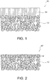
- a functional layer 14 as an LDH dense membrane is formed preferably on a porous substrate 12 in an LDH-containing composite material 10, for example.
- the porous substrate 12 allows LDH to be formed in pores in the surface and its vicinity of the porous substrate 12 as shown in Fig. 1 .
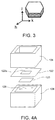
- high density LDH may be formed in the porous substrate 12 (for example, in pores in the surface and its vicinity of the porous substrate 12), whereby at least a portion of the porous substrate 12 may constitute a functional layer 14'.
- the composite material 10' shown in Fig. 2 lacks a pure membrane portion of the functional layer 14 of the composite material 10 in Fig. 1 .
- the functional layer 14' may have any other structure parallel to the surface of the porous substrate 12. If the functional layer is composed of a highly-densified LDH and exhibits water impermeability in the LDH-containing composite material of the present invention, the composite material can have a unique function; i.e., both hydroxide ion conductivity and water impermeability.
- the LDH-containing composite material of the present invention has the porous substrate which exhibits water permeability and, nevertheless, preferably has the dense functional layer which exhibits water impermeability (desirably both water impermeability and gas impermeability).
- the LDH-containing composite material of the present invention as a whole exhibits hydroxide ion conductivity but exhibits water impermeability, and thus can function as a separator of a battery.
- LDH dense bulk blocks are not suitable for solid electrolyte separators of batteries due to their high resistivity, as described above.
- the functional layer of the composite material of the present invention can be thin and have low resistivity by virtue of the porous substrate which gives strength to the composite material of the present invention.
- the porous substrate may exhibit water permeability, whereby the electrolyte solution can come into contact with the LDH-containing functional layer when the composite material of the present invention is used as a solid electrolyte separator of a battery. That is, the LDH-containing composite material of the present invention is very useful as a material of a solid electrolyte separator of various batteries, such as metal-air batteries (e.g., zinc-air batteries) and other zinc secondary batteries (e.g., nickel-zinc batteries).
- metal-air batteries e.g., zinc-air batteries
- other zinc secondary batteries e.g., nickel-zinc batteries
- the porous substrate in the composite material of the present invention is one on and/or in which the LDH-containing functional layer can be formed.
- the porous substrate may be composed of any material and may have any porous structure.
- the LDH-containing functional layer is formed on and/or in the porous substrate.
- the LDH-containing functional layer may be formed on a non-porous substrate, and then the non-porous substrate may be modified into a porous form by any known method.
- the porous substrate preferably has a porous structure that give water permeability to the porous substrate because, by virtue of such a porous structure, an electrolyte solution can come into contact with the functional layer in the case where the composite material is used as a separator of a battery.
- the porous substrate is preferably composed of at least one selected from the group consisting of ceramics, metals and polymers. More preferably, the porous substrate is composed of a ceramic.
- the ceramics include alumina, zirconia, titania, magnesia, spinel, calcia, cordierite, zeolite, mullite, ferrite, zinc oxide, silicon carbide, and a combination thereof.
- Alumina, zirconia, titania, and a combination thereof are more preferred.
- Alumina, zirconia (e.g., yttria-stabilized zirconia (YSZ)), and a combination thereof are further preferred.
- Use of these porous ceramic facilitates formation of a high density LDH-containing functional layer.
- Preferred examples of the metals include aluminum and zinc.
- Preferred examples of the polymers include polystyrene, polyether sulfone, polypropylene, epoxy resins, polyphenylene sulfide, hydrophilized fluororesins (e.g., poly(tetrafluoroethylene) (PTFE)), and a combination thereof.
- the preferred materials described above all have alkali resistance, in other words, resistance to an electrolyte solution of a battery.
- the porous substrate has an average pore diameter of preferably from 0.001 to 1.5 ⁇ m, more preferably from 0.001 to 1.25 ⁇ m, still more preferably from 0.001 to 1.0 ⁇ m, particularly preferably from 0.001 to 0.75 ⁇ m, and most preferably from 0.001 to 0.5 ⁇ m.
- the average pore diameter can be measured by measuring the longest diameter of each pore in an electron microscopic image of the surface of the porous substrate. The magnification of the electron microscopic image used in this measurement is not less than 20,000.
- All of the measured pore diameters are listed in the ascending order from the shortest one to calculate the average, from which the subsequent 15 larger diameters and the subsequent 15 smaller diameters, i.e., 30 diameters in total, are selected in one field of view. Subsequently, the selected diameters of two fields of view are averaged to obtain the average pore diameter.
- the diameters can be measured by, for example, a length-measuring function of a SEM or an image analysis software (e.g., Photoshop, Adobe).
- the surface of the porous substrate has a porosity of preferably from 10 to 60%, more preferably from 15 to 55%, and further more preferably from 20 to 50%. These ranges make it possible to form a dense LDH-containing functional layer that exhibits water impermeability while ensuring desired water permeability of the porous substrate and desired strength as a support.
- the surface porosity of the porous substrate is adopted because it can readily be measured by image processing described below and substantially reflects the internal porosity of the porous substrate. In other words, if the surface of the porous substrate is dense, the inside of the porous substrate is dense, too.
- the porosity at the surface of the porous substrate can be measured by a method involving image processing, in accordance with the following procedures: 1) an electron microscopic (SEM) image of the surface of the porous substrate is taken at a magnification of not less than 10,000; 2) the grayscale SEM image is read with an image analysis software, such as Photoshop (Adobe); 3) a monochromatic binary image is generated with tools named [image], [color compensation] and [binarization] in this order; and 4) the porosity (%) is calculated by dividing the number of pixels of the black area(s) by the number of the pixels of the whole image.
- SEM electron microscopic
- the porosity is measured over a 6 ⁇ m ⁇ 6 ⁇ m area of the surface of the porous substrate by image processing. More preferably, the porosity is determined by averaging the porosity in three 6 ⁇ m ⁇ 6 ⁇ m areas selected at random for objective evaluation.
- the functional layer in the composite material of the present invention comprises a layered double hydroxide (LDH) represented by the general formula M 2+ 1-x M 3+ x (OH) 2 A n- x/n ⁇ mH 2 O (where M 2+ represents a divalent cation, M 3+ represents a trivalent cation, A n- represents an n-valent anion, n represents an integer not less than 1, x represents a value of 0.1 to 0.4, and m represents any real number).
- LDH layered double hydroxide
- M 2+ represents a divalent cation
- M 3+ represents a trivalent cation
- a n- represents an n-valent anion
- n represents an integer not less than 1
- x represents a value of 0.1 to 0.4
- m represents any real number
- the functional layer exhibits water impermeability.
- M 2+ may represent any divalent cation; preferably, M 2+ represents, for example, Mg 2+ , Ca 2+ and/or Zn 2+ , and more preferably Mg 2+ .
- M 3+ may represent any trivalent cation; preferably, M 3+ represents, for example, Al 3+ and/or Cr 3+ , and more preferably Al 3+ .
- a n- may represent any anion, and preferably, for example, OH - and/or CO 3 2- .
- M 2+ comprises Mg 2+
- M 3+ comprises Al 3+
- a n- comprises OH - and/or CO 3 2- .
- n represents an integer not less than 1, and preferably 1 or 2;
- x represents a value of 0.1 to 0.4, and preferably 0.2 to 0.35; and
- m represents any real number.
- m represents a value not less than 0, and more preferably a real number or an integer more than 0 or not less than 1.
- the functional layer further contains sulfur (S) at the interface between the functional layer and the porous substrate and in the vicinity of the interface.
- S sulfur
- the incorporation of S leads to an increase in conductivity.
- the sulfur content at the interface between the functional layer and the porous substrate and in the vicinity of the interface is preferably 0.01 atom% or more, more preferably 0.05 to 5.0 atom%, still more preferably 0.1 to 2.0 atom%, particularly preferably 0.2 to 1.0 atom%.
- the sulfur (S) content can be determined by EDS compositional analysis (cross-sectional EDS point analysis) at the interface between the functional layer and the porous substrate and in the vicinity of the interface. In detail, the S content is preferably determined as described below.
- a cross section of a composite material sample (including a functional layer and a porous substrate) is polished with a cross section polisher (CP) for observation of the polished surface.
- Cross-sectional images of the composite material sample are observed with an FE-SEM at a magnification of 15,000 or more (three visual fields).
- Compositional analysis point analysis
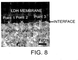
- Compositional analysis is performed at any three points at the interface between the LDH membrane and the porous substrate of each of the three visual-field images (i.e., nine points in total) with an EDS analyzer (accelerating voltage: 10 kV, acquisition time: 100 seconds).
- the S content (atom%) at each point is determined by the compositional analysis, and the S contents at the nine points are averaged. The average value is defined as the S content at the interface.
- the EDS compositional analysis targeted for the interface may acquire some data in the vicinity of the interface; i.e., data in a region several ⁇ m distant from the analyzed point.
- the expression "the interface and in the vicinity of the interface” used herein generally refers to the interface itself, and can also include a region several ⁇ m or less distant from the interface (e.g., a region 0.5 ⁇ m or less distant from the interface) in which incidental data are acquired by the EDS compositional analysis targeted for the interface.
- the functional layer may further contain carbon (C) at the interface between the functional layer and the porous substrate and in the vicinity of the interface.
- C carbon
- the incorporation of C leads to a further increase in conductivity.
- the maximum carbon content (i.e., carbon (C) atom content) at the interface between the functional layer and the porous substrate and in the vicinity of the interface is preferably 10 atom% or more, more preferably 20 atom% or more, still more preferably 30 atom% or more, particularly preferably 50 atom% or more.
- the maximum carbon content may be 100 atom% and is typically 80 atom% or less.
- the carbon (C) content can be determined by EDS compositional analysis (acquisition of a line profile of carbon concentration by cross-sectional EDS) at the interface between the functional layer and the porous substrate and in the vicinity of the interface.
- the C content is preferably determined as described below.
- a cross section of a composite material sample (including a functional layer and a porous substrate) is polished with a cross section polisher (CP) for observation of the polished surface.
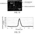
- a cross-sectional image of the composite material sample (including the LDH membrane and the porous substrate) is observed with an FE-SEM at a magnification of 10,000 or more (refer to, for example, the image illustrated in Fig. 12 ).
- the image is analyzed with an EDS analyzer (accelerating voltage: 5 kV) to acquire a line profile of carbon concentration (i.e., carbon atom C concentration (atom%)) across the interface between the LDH membrane and the porous substrate at a predetermined pitch (e.g., 0.06 ⁇ m) over a length of 3 ⁇ m from the LDH membrane toward the porous substrate, for example, as shown by the dotted arrow in Fig. 12 .
- the resultant line profile of carbon concentration is used to determine the presence of the maximum carbon content at the interface and in the vicinity thereof.
- the EDS compositional analysis targeted for the interface may acquire some data in the vicinity of the interface; i.e., data in a region several ⁇ m distant from the analyzed point.
- the expression "the interface and in the vicinity of the interface” used herein generally refers to the interface itself, and can also include a region several ⁇ m or less distant from the interface (e.g., a region 0.5 ⁇ m or less distant from the interface) in which incidental data are acquired by the EDS compositional analysis targeted for the interface.
- the functional layer is formed on and/or in the porous substrate, and preferably on the porous substrate.
- the functional layer 14 is an LDH dense membrane. Typically, this LDH dense membrane consists of LDH.
- high density LDH is formed in the porous substrate 12 (typically in pores in the surface and its vicinity of the porous substrate 12), whereby the functional layer 14' is composed of at least a portion of the porous substrate 12 and LDH.
- the composite material 10' and the functional layer 14' shown in Fig. 2 can be produced by removing the pure membrane portion of the functional layer 14 from the composite material 10 shown in Fig.1 by polishing, grinding or any other known method.
- the functional layer preferably exhibits water impermeability (desirably both water impermeability and gas impermeability).
- the functional layer does not let water pass through the surface for a week during which this surface is in contact with the water at 25°C.
- the functional layer is preferably composed of high density LDH and exhibits water impermeability. If local and/or incidental defects that exhibit water permeability are present in or on the functional layer, such defects may be filled with an adequate repairing material (e.g., an epoxy resin) to achieve water impermeability. Such a putty does not necessarily exhibit hydroxide ion conductivity.
- the layered double hydroxide is composed of an agglomeration of platy particles (i.e., platy LDH particles).
- platy LDH particles are oriented in such a manner that the tabular faces of the platy particles are substantially perpendicular to or oblique to the surface of the porous substrate (i.e., the substrate surface).
- This embodiment can be preferably attained especially when the functional layer 14 is formed as an LDH dense membrane on the porous substrate 12 to form the LDH-containing composite material 10 as shown in Fig. 1 .
- This embodiment can also be attained when high density LDH is formed in the porous substrate 12 (typically, in pores in the surface and its vicinity of the porous substrate 12), whereby at least a portion of the porous substrate 12 constitutes the functional layer 14' as in the LDH composite material 10' shown in Fig. 2 .
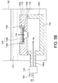
- the LDH crystal has a form of a platy particle with a layered structure as shown in Fig. 3 .
- the substantially perpendicular or oblique orientation described above is significantly beneficial for the LDH-containing functional layer (e.g., the LDH dense membrane), because an oriented LDH-containing functional layer (e.g., an oriented LDH dense membrane) exhibits anisotropic hydroxide ion conductivity, i.e., hydroxide ion conductivity along the orientation of the platy LDH particles (i.e., parallel to layers of LDH) is much greater than hydroxide ion conductivity perpendicular to the orientation of the platy LDH particles in the oriented-LDH-containing functional layer.
- the present inventors have revealed that, the hydroxide ion conductivity (S/cm) along the orientation of LDH particles in an oriented LDH bulk body is an order of magnitude greater than the hydroxide ion conductivity (S/cm) perpendicular to the orientation of LDH particles.
- the substantially perpendicular or oblique orientation in the LDH-containing functional layer of the present invention fully or significantly educes the anisotropic hydroxide ion conductivity of the oriented LDH to the thickness direction of the layer (i.e., the direction perpendicular to the surface of the functional layer or the surface of the porous substrate), whereby the conductivity along the thickness direction can be maximally or significantly increased.
- the LDH-containing functional layer of the present invention exhibits lower resistivity than an LDH bulk block by virtue of its layered shape.
- the LDH-containing functional layer with such an orientation readily conducts hydroxide ions along the thickness direction of the layer. Since the LDH-containing functional layer has high density, it is significantly appropriate for use in a functional layer that requires high conductivity across the thickness of the layer and high density, such as a separator of a battery (e.g., a hydroxide ion conductive separator of a zinc-air battery).
- the LDH-containing functional layer (typically the LDH dense membrane) should be composed of the platy LDH particles highly oriented in the substantially perpendicular direction. If the platy LDH particles are highly orientated in the substantially perpendicular direction, X-ray diffractometry of the surface of the functional layer shows no peak of (003) plane or a peak of (003) plane smaller than that of (012) plane (note that this shall not apply to the case where the porous substrate shows a peak at the same angle as a peak of (012) plane of the platy LDH particles, because a peak of (012) plane of the platy LDH particles cannot be distinguished).
- This characteristic peak profile indicates that the platy LDH particles of the functional layer are oriented substantially perpendicular to (i.e, perpendicular to or nearly perpendicular to, and preferably perpendicular to) the functional layer.
- the peak of (003) plane is strongest among peaks observed in X-ray diffractometry of non-oriented LDH powder.
- the oriented LDH-containing functional layer shows no peak of (003) plane or a peak of (003) plane smaller than a peak of (012) plane because platy LDH particles are oriented substantially perpendicular to the functional layer. This can be explained as follows:
- the c planes (00I) including the (003) plane (note that I is 3 or 6) are parallel to the layers of platy LDH particles.
- the layers of platy LDH particles are also perpendicular to the functional layer and thus the X-ray diffractometry of the surface of the functional layer shows no peak or hardly shows a peak of (00I) plane.
- the peak of (003) plane is often stronger, if present, than the peak of (006) plane, and use of the peak of (003) plane can more readily confirm the substantially perpendicular orientation than use of the peak of (006) plane.
- the oriented LDH-containing functional layer preferably shows no or substantially no peak of (003) plane or shows a peak of (003) plane smaller than a peak of (012) plane, which indicates that the highly perpendicular orientation is achieved.
- oriented LDH membranes of Patent Documents 1 and 2 and Non-Patent Document 1 each show a strong peak of (003) plane, which indicates that the substantially perpendicular orientation is not satisfactorily achieved.
- the membranes of these Documents are not dense.
- the thickness of the functional layer is preferably not more than 100 ⁇ m, more preferably not more than 75 ⁇ m, still more preferably not more than 50 ⁇ m, further more preferably not more than 25 ⁇ m, and most preferably not more than 5 ⁇ m.
- the thin functional layers having such a thinness exhibits low resistivity.
- the functional layer is preferably formed on the porous substrate as the LDH dense membrane. In this case, the thickness of the functional layer is the thickness of the LDH dense membrane. In the case where the functional layer is formed in the porous substrate, the thickness of the functional layer is the thickness of a composite layer composed of at least a portion of the porous substrate and LDH.
- the thickness of the functional layer is the sum of the thickness of the LDH dense membrane and the thickness of the composite layer.
- the thickness of the functional layer having the above thinness exhibits low resistivity desirable for use in, for example, a battery.
- the thickness of the oriented LDH-containing functional layer does not have a lower limit, which depends on its use.
- the thickness is preferably not less than 1 ⁇ m, and more preferably not less than 2 ⁇ m.
- the layered-double-hydroxide-containing composite material can be produced by: (1) preparing a porous substrate; (2) depositing sulfur (S) on the porous substrate, (3) soaking the porous substrate in an aqueous stock solution that contains magnesium ions (Mg 2+ ) and aluminum ions (Al 3+ ) in a total concentration of 0.20 to 0.40 mol/L and urea; and (4) hydrothermally treating the porous substrate in the aqueous stock solution to form a layered-double-hydroxide-containing functional layer on and/or in the porous substrate.
- S sulfur
- Al 3+ aluminum ions
- the porous substrate is one as described above.
- the porous substrate is composed of at least one selected from the group consisting of ceramics, metals, and polymers. More preferably, the porous substrate is composed of a ceramic.
- the ceramics include alumina, zirconia, titania, magnesia, spinel, calcia, cordierite, zeolite, mullite, ferrite, zinc oxide, silicon carbide, and a combination thereof.
- Alumina, zirconia, titania and a combination thereof are more preferred.
- Alumina and zirconia are further preferred, and alumina is most preferred.
- Use of these porous ceramic facilitates the formation of the high density LDH-containing functional layer.
- the porous substrate is preferably cleaned, for example, by ultrasonic cleaning or with ion-exchanged water.
- the porous substrate is more preferably composed of a ceramic material.
- the ceramic porous substrate may be a commercially available one or may be prepared by any known process.
- the ceramic porous substrate may be prepared as follows: Ceramic powder (e.g., zirconia powder, boehmite powder, or titania powder), methyl cellulose, and deionized water are mixed in predetermined proportions; the resultant mixture is subjected to extrusion molding; the molded product is dried at 70 to 200°C for 10 to 40 hours; and the dried product is fired at 900 to 1,300°C for one to five hours.
- the amount of methyl cellulose is preferably 1 to 20 parts by weight relative to 100 parts by weight of the ceramic powder.
- the amount of deionized water is preferably 10 to 100 parts by weight relative to 100 parts by weight of the ceramic powder.
- the porous substrate may be composed of a polymer material.
- a sulfonatable polymer substrate is preferably provided because such a substrate is suitable for the subsequent step of sulfur deposition.
- the sulfonatable polymer substrate preferably has alkali resistance, i.e., resistance to an electrolyte solution of a battery.
- the sulfonatable polymer substrate is preferably composed of at least one selected from the group consisting of polystyrene, polyether sulfone, polypropylene, epoxy resins, polyphenylene sulfide, hydrophilized fluororesins (e.g., poly(tetrafluoroethylene) (PTFE)).
- PTFE poly(tetrafluoroethylene)
- Aromatic polymer substrates are particularly preferred because they are readily sulfonated.
- the aromatic polymer substrates include substrates composed of at least one selected from the group consisting of polystyrene, polyether sulfone, polypropylene, an epoxy resin, and polyphenylene sulfide. Most preferably, the aromatic polymer substrate is composed of polystyrene.
- S may be deposited on the porous substrate by any process, but is preferably deposited by sulfonation.
- the sulfonation may be performed by soaking a sulfonatable substrate or a substrate whose surface has been treated to be sulfonatable in an acid for sulfonating the sulfonatable substrate or surface, such as sulfuric acid (e.g., concentrated sulfuric acid), fuming sulfuric acid, chlorosulfuric acid, and sulfuric anhydride. Any other sulfonation techniques may also be used.
- the soaking in an acid for the sulfonation may be performed at room temperature or high temperature (e.g., 50 to 150°C).
- the soaking may be performed for any period of time (e.g., 1 to 14 days).
- the sulfonatable substrate is preferably, for example, a polymer substrate.
- the sulfonatable polymer substrate is as described above. If the porous substrate is unsulfonatable or unsuitable for sulfonation (e.g., a ceramic substrate), the porous substrate may be subjected to surface treatment such that the substrate can be sulfonated as in the aforementioned sulfonatable substrate.
- the surface treatment preferably involves deposition of a polymer on the substrate.
- the polymer is preferably a polymer material similar to that used for the aforementioned sulfonatable polymer substrate.
- the deposition of the polymer on the substrate preferably involves application of a polymer solution to the surface of the substrate.
- the polymer solution can be readily prepared by, for example, dissolution of a solid polymer (e.g., a polystyrene substrate) in an organic solvent (e.g., xylene).
- a solid polymer e.g., a polystyrene substrate
- organic solvent e.g., xylene
- spin coating is preferably used for very even deposition or application of the polymer solution.
- the spin coating may be performed under any conditions; for example, a rotation rate of 1,000 to 10,000 rpm and an operational period of about 60 to 300 seconds (including dropwise addition and drying).
- sulfur (S) is deposited on the porous substrate after the deposition of carbon (C) on the porous substrate.
- carbon typically a carbon membrane or layer
- the aforementioned sulfonation is performed on the carbon-deposited surface (typically the surface of the carbon membrane or layer).
- Carbon is preferably vapor-deposited on the porous substrate.
- the vapor deposition of carbon may be performed with a commercially available deposition apparatus by any known technique, such as flash deposition.
- the substrate is preferably rotated during vapor deposition of the carbon.
- the deposition of carbon on the porous substrate preferably involves application of a resin to the substrate and carbonization of the resin, more preferably involves application of a resin to the substrate, thermal curing of the resin, and carbonization of the resin.
- the resin may be of any type that can be carbonized.
- the resin is preferably, for example, a polyimide resin, a lignin resin, or a phenolic resin, particularly preferably a polyimide resin.
- the resin applied to the substrate is preferably in the form of a solution (e.g., a varnish).
- the resin solution is preferably applied to the substrate such that the solution does not permeate the substrate.
- spin coating is preferably used for very even deposition or application of the resin.
- the spin coating may be performed under any conditions; for example, a rotation rate of 1,000 to 10,000 rpm and an operational period of about 60 to 300 seconds (including dropwise addition and drying).
- the thermal curing of the resin preferably involves heating of the resin in air at 100 to 300°C for 1 to 10 hours.
- the carbonization of the resin preferably involves heating of the resin under vacuum at 500 to 1,000°C for 1 to 10 hours.
- the porous substrate is soaked in an aqueous stock solution in a target direction (preferably horizontally or perpendicularly).
- a target direction preferably horizontally or perpendicularly.
- the porous substrate may be hanged up in, suspended in or put on the bottom of a container of the aqueous stock solution.
- the porous substrate may be immobilized and suspended in the stock solution and away from the bottom of the solution container.
- a fixture may be disposed that can holds the porous substrate perpendicularly to the bottom of the solution container.
- a preferred configuration or arrangement is one that forms LDH substantially perpendicular (i.e., grows platy LDH particles oriented in such a manner that the tabular faces of the platy particles are substantially perpendicular to or oblique to the surface of the porous substrate) over, on and/or in the porous substrate.
- the aqueous stock solution contains magnesium ions (Mg 2+ ) and aluminum ions (Al 3+ ) in a certain total concentration and urea. Urea is hydrolyzed into ammonia and raises the pH of the aqueous stock solution, and metal ions co-existing in the aqueous stock solution are converted into hydroxides, whereby LDH is formed.
- the urea hydrolysis which also generates carbon dioxide, can form LDH having carbonate ions as anions.
- the aqueous stock solution contains magnesium ions (Mg 2+ ) and aluminum ions (Al 3+ ) in a total concentration of preferably 0.20 to 0.40 mol/L, more preferably 0.22 to 0.38 mol/L, further more preferably 0.24 to 0.36 mol/L, and most preferably 0.26 to 0.34 mol/L. These concentration ranges facilitate the nucleation and the crystal growth in a balanced manner and can form a highly-oriented high-density LDH-containing functional layer.
- the crystal growth dominates over the nucleation, resulted in a decrease in the number of the LDH particles and an increase in the size of the LDH particles.
- the nucleation dominates over the crystal growth, resulted in an increase in the number of the LDH particles and a decrease in the size of the LDH particles.
- the aqueous stock solution preferably contains dissolved magnesium nitrate and aluminum nitrate, and the aqueous stock solution thereby contains nitrate ions in addition to the magnesium ions and the aluminum ions.
- a molar ratio of the urea to the nitrate ions (NO 3 - ) (i.e., urea/NO 3 - ) in the aqueous stock solution ranges preferably from 2 to 6, and more preferably from 4 to 5.
- hydrothermal treatment of the porous substrate is performed in the aqueous stock solution to form the LDH-containing functional layer on and/or in the porous substrate.
- the hydrothermal treatment is performed in a sealed container at a temperature of preferably 60 to 150°C, more preferably 65 to 120°C, further more preferably 65 to 100°C, and most preferably 70 to 90°C.
- the hydrothermal treatment temperature may have any upper limit within the scope not causing thermal deformation of the porous substrate (e.g., the polymer substrate). The temperature can be raised at any rate in the hydrothermal treatment.
- the heating rate may range from 10 to 200°C/h, preferably from 100 to 200°C/h, and more preferably from 100 to 150°C/h.
- the time for the hydrothermal treatment may be determined depending on a target density and a target thickness of the LDH-containing functional layer.
- the porous substrate is taken out from the sealed container, and then preferably cleaned with ion-exchanged water.
- the resulting LDH-containing functional layer of the LDH-containing composite material is composed of densely assembled platy LDH particles that are oriented in the substantially perpendicular direction, which direction is beneficial for the conductivity.
- the electricity generating capacity will increase.
- this dense LDH-containing functional layer is expected to be applicable to novel applications, such as a separator that can prevent zinc dendrite growth and carbon dioxide incorporation, which have been large technical barriers against forming a zinc-air secondary battery containing an electrolyte solution that has not been achieved.
- This dense LDH-containing functional layer can also be used in a separator of a nickel-zinc battery which has been known to cause growth of zinc dendrite growth being an obstacle for practical use of this battery.
- the LDH-containing functional layers can be formed on and/or in both surfaces of the porous substrate by the above-described method.
- machine grinding of a LDH-containing functional layer on one surface of the porous substrate is preferably performed after the formation of the LDH-containing functional layers.
- Oriented layered double hydroxide membranes were formed on porous substrates in Examples described below.
- the membrane samples prepared in the Examples were evaluated as follows.
- a crystalline phase of a membrane sample is analyzed with an X-ray diffractometer (RINT-TTR III, manufactured by Rigaku Corporation) at a voltage of 50 kV, a current of 300 mA, and a measuring range of 10° to 70°.
- the resultant XRD profile is compared with the diffraction peaks of a layered double hydroxide (or a hydrotalcite compound) described in JCPDS card No. 35-0964 for identification of the membrane sample.
- the surface microstructure of the membrane sample was observed with a scanning electron microscope (SEM; JSM-6610LV, manufactured by JEOL Ltd.) at an acceleration voltage of 10 to 20 kV.
- SEM scanning electron microscope
- a density evaluation test was performed on the membrane sample for determining whether the sample has high density and thus water impermeability.
- a silicone rubber 122 having a central opening 122a (0.5 cm ⁇ 0.5 cm) was bonded to the membrane sample of LDH-containing composite material sample 120 (cut into a piece of 1 cm ⁇ 1 cm), and the resultant laminate was disposed between two acrylic units 124 and 126 and bonded to these acrylic units.
- the acrylic unit 124 disposed on the silicone rubber 122 has no bottom, and thus the silicone rubber 122 is bonded to the acrylic unit 124 such that the opening 122a is exposed.
- the acrylic unit 126 disposed on the porous substrate side in view of composite material sample 120 has a bottom and contains ion-exchange water 128.
- ion-exchange water 128 may be dissolved in the ion-exchange water.
- these components are arranged to form an assembly such that the ion-exchange water 128 comes into contact with the porous substrate of composite material sample 120 if the assembly is inverted upside down.
- the unit 126 has a closed vent (not shown) and the vent is opened after inversion of the assembly. As illustrated in Fig. 4B , the assembly was inverted and left for one week at 25°C, and then the total weight thereof was measured again.
- the membrane sample was evaluated on the basis of the difference between the total weights of the assembly before and after the inversion. When no change in weight of the ion-exchange water is observed even after the one-week test at 25°C, the membrane sample (i.e., functional membrane) was evaluated as having high density so as to exhibit water impermeability.
- a density evaluation test was performed on the membrane sample for determining whether the sample has high density and thus gas impermeability.
- an acrylic container 130 and an alumina jig 132 were provided.
- the container 130 has no lid, and the jig 132 has a shape and a size such that it serves as a lid for the container 130.
- the acrylic container 130 has a gas inlet 130a for feeding a gas into the container 130.
- the alumina jig 132 has an opening 132a having a diameter of 5 mm, and a dent 132b provided around the opening 132a for supporting the membrane sample.
- An epoxy adhesive 134 was applied to the dent 132b of the alumina jig 132, and a membrane sample 136b of a composite material sample 136 was placed on the dent 132b and gas-and liquid-tightly bonded to the alumina jig 132.
- the alumina jig 132 provided with the composite material sample 136 was gas- and liquid-tightly bonded to the upper edge of the acrylic container 130 with a silicone adhesive 138 so as to completely cover the opening of the acrylic container 130, to prepare a hermetic container 140 for evaluation.
- the hermetic container 140 was placed in a water bath 142, and the gas inlet 130a of the acrylic container 130 was connected to a pressure gauge 144 and a flowmeter 146 so as to allow helium gas to be fed into the acrylic container 130.
- Water 143 was poured into the water bath 142 such that the hermetic container 140 was completely submerged in the water.
- the hermetic container 140 was ensured to have gas tightness and liquid tightness.
- the membrane sample 136b of the composite material sample 136 was exposed to the inner space of the hermetic container 140, and the porous substrate 136a of the composite material sample 136 was in contact with the water in the water bath 142.
- Helium gas was fed into the hermetic container 140 through the gas inlet 130a of the acrylic container 130.
- the pressure gauge 144 and the flowmeter 146 were monitored to achieve a differential pressure of 0.5 atm at the membrane sample 136b (i.e., the pressure applied to the surface in contact with helium gas was higher by 0.5 atm than water pressure applied to the opposite surface), to determine the presence of helium gas bubbles in the water caused by permeation of helium gas through the composite material sample 136. When no helium gas bubbles were observed, the membrane sample 136b was evaluated as having high density so as to exhibit gas impermeability.
- a cross section of a composite material sample (including an LDH membrane and a porous substrate) was polished with a cross section polisher (CP) for observation of the polished surface.
- Cross-sectional images of the composite material sample were observed with an FE-SEM (ULTRA55, manufactured by Carl Zeiss) at a magnification of 15,000 or more (three visual fields).
- Compositional analysis (point analysis) was performed at any three points at the interface between the LDH membrane and the porous substrate of each of the three visual-field images (i.e., nine points in total) with an EDS analyzer (NORAN System SIX, manufactured by Thermo Fisher Scientific Inc.) (accelerating voltage: 10 kV, acquisition time: 100 seconds).
- the S content (atom%) at each point was determined by the compositional analysis, and the S contents at the nine points were averaged. The average value was defined as the S content at the interface.
- the conductivity of a membrane sample in an electrolytic solution was determined with an electrochemical measuring system illustrated in Fig. 6 as follows.
- a composite material sample S (a porous substrate provided with an LDH membrane) was sandwiched between silicone packings 40 (thickness: 1 mm each) and placed in a PTFE flange cell 42 having an inner diameter of 6 mm.
- Electrodes 46 (cylindrical electrodes composed of #100-mesh nickel netting and having a diameter of 6 mm) were placed in the cell 42 such that the distance between the electrodes was 2.2 mm.
- the cell 42 was filled with an electrolytic solution 44 (6M aqueous KOH solution).
- the resistance of the composite material sample (the porous substrate provided with the LDH membrane) was determined with an electrochemical measuring system (potentio/galvanostat-frequency response analyzer, Model Nos. 1287A and 1255B, manufactured by Solartron) at a frequency of 1 MHz to 0.1 Hz and a voltage of 10 mV. The intercept on the real axis was defined as the resistance of the sample.
- the resistance of a porous substrate having no LDH membrane was also determined as described above.
- the difference between the resistance of the composite material sample S (the porous substrate provided with the LDH membrane) and that of the substrate was defined as the resistance of the LDH membrane.
- the conductivity of the LDH membrane was calculated from the resistance, thickness, and area of the LDH membrane.
- a cross section of a composite material sample (including an LDH membrane and a porous substrate) was polished with a cross section polisher (CP) for observation of the polished surface.
- a cross-sectional image of the composite material sample (including the LDH membrane and the porous substrate) was observed with an FE-SEM (ULTRA55, manufactured by Carl Zeiss) at a magnification of 10,000 (refer to, for example, the image illustrated in Fig. 12 ).
- the image was analyzed with an EDS analyzer (NORAN System SIX, manufactured by Thermo Fisher Scientific Inc.) (accelerating voltage: 5 kV) to acquire a line profile of carbon concentration (i.e., carbon (C) atom concentration (atom%)) across the interface between the LDH membrane and the porous substrate at a pitch of 0.06 ⁇ m over a length of 3 ⁇ m from the LDH membrane toward the porous substrate as shown by the dotted arrow in Fig. 12 .
- the resultant line profile of carbon concentration was used to determine the presence of the maximum carbon content at the interface and in the vicinity thereof.
- Zirconia (8YSZ) powder (TZ-8YS, Y 2 O 3 : 8 mol%, manufactured by Tosoh Corporation), methyl cellulose, and ion-exchange water were weighed in proportions by mass of 10:1:5, and were then kneaded together.
- the kneaded product was subjected to extrusion molding with a hand press into a size of 2.5 cm ⁇ 10 cm ⁇ 0.5 cm in thickness.
- the resultant green body was dried at 80°C for 12 hours and then fired at 1,100°C for three hours.
- the resultant product was processed into a zirconia (8YSZ) porous substrate having dimensions of 2.0 cm by 2.0 cm by 0.3 cm (thickness).
- the porosity at the surface of the resultant porous substrate was determined by a method involving image processing.
- the porosity was 42.5%.
- the porosity was determined as follows: 1) a scanning electron microscopic (SEM) image of the surface microstructure of the porous substrate was taken with a scanning electron microscope (SEM; JSM-6610LV, manufactured by JEOL Ltd.) (magnification: 10,000 or more) at an acceleration voltage of 10 to 20 kV; 2) the grayscale SEM image was read with image analysis software, such as Photoshop (manufactured by Adobe); 3) a monochromatic binary image was prepared with tools named [image], [color compensation], and [binarization] in this order; and 4) the porosity (%) was determined by dividing the number of pixels of the black areas by the number of all the pixels of the image. The porosity was determined over a 6 ⁇ m ⁇ 6 ⁇ m area of the surface of the porous substrate.
- the average pore size of the porous substrate was about 0.22 ⁇ m.
- the average pore size was determined by measuring the largest length of each pore in a scanning electron microscopic (SEM) image of the surface of the porous substrate.
- the magnification of the scanning electron microscopic (SEM) image used in this measurement was 20,000. All the measured pore sizes were listed in order of size to calculate the average, from which the subsequent 15 larger sizes and the subsequent 15 smaller sizes, i.e., 30 sizes in total, were selected in one field of view. The selected sizes of two fields of view were then averaged to yield the average pore size.
- the pore sizes were measured by, for example, a length-measuring function of SEM software.
- the resultant porous substrate was ultrasonically cleaned in acetone for five minutes, in ethanol for two minutes, and then in ion-exchange water for one minute.
- a polystyrene substrate (0.6 g) was dissolved in xylene (10 mL) to prepare a coating solution having a polystyrene concentration of 0.06 g/mL.
- the coating solution (0.1 mL) was added dropwise and applied to the 8YSZ porous substrate by a spin coating process at 8,000 rpm for 200 seconds (including dropwise addition and drying).
- the spin-coated porous substrate was sulfonated through immersion in 95% sulfuric acid at 25°C for four days.
- Magnesium nitrate hexahydrate (Mg(NO 3 ) 2 ⁇ 6H 2 O, manufactured by KANTO CHEMICAL Co., Inc.), aluminum nitrate nonahydrate (Al(NO 3 ) 3 ⁇ 9H 2 O, manufactured by KANTO CHEMICAL Co., Inc.), and urea ((NH 2 ) 2 CO, manufactured by Sigma-Aldrich Corporation) were provided as raw materials for an aqueous stock solution.
- Magnesium nitrate hexahydrate and aluminum nitrate nonahydrate were weighed and placed in a beaker, and then ion-exchange water was added to the beaker to achieve a total volume of 75 mL, a ratio of the cations (Mg 2+ /Al 3+ ) of 2, and a molar concentration of the total metal ions (i.e., Mg 2+ and Al 3+ ) of 0.320 mol/L.
- the resultant solution was agitated and urea was then added to the solution.
- the added urea was weighed in advance to give a urea/NO 3 - ratio of 4.
- the resultant solution was further agitated to prepare an aqueous stock solution.
- the aqueous stock solution prepared in the above procedure (3) and the porous substrate sulfonated in the above procedure (2) were enclosed together in a hermetic Teflon (registered trademark) container (with an internal volume of 100 mL and a stainless steel jacket).
- the porous substrate was horizontally suspended and away from the bottom of the hermetic Teflon (registered trademark) container such that the opposite surfaces of the porous substrate came into contact with the aqueous stock solution. Thereafter, the porous substrate was subjected to hydrothermal treatment at a hydrothermal temperature of 70°C for 168 hours (7 days) to form oriented layered double hydroxide membranes (functional layers) on the surfaces of the substrate.
- the porous substrate was removed from the hermetic container, cleaned with ion-exchange water, and then dried at 70°C for 10 hours, to form a dense membrane of the layered double hydroxide (LDH) on the porous substrate (hereinafter the dense membrane will be referred to as "membrane sample").
- the thickness of the membrane sample was about 1.5 ⁇ m.
- a layered-double-hydroxide-containing composite material sample (hereinafter referred to as "composite material samples”) was thereby prepared. LDH membranes were formed on the opposite surfaces of the porous substrate. In order to use the composite material as a separator, the LDH membrane on one surface of the porous substrate was mechanically removed.
- the resultant LDH membrane sample was evaluated.
- the results of evaluations 1 to 7 are described below.
- An 8YSZ porous substrate was prepared and cleaned as in Example 1 (1).
- the 8YSZ porous substrate was placed in an autoclave.
- An LDH membrane was formed and evaluated as in Example 1 (3) and (4), except that i) neither polystyrene spin coating nor sulfonation (the aforementioned procedure (2)) was performed, and ii) Al(OH) 3 was nucleated on the surface of the substrate through hydrothermal treatment at 60°C for four days in the same aqueous stock solution before the seven-day hydrothermal treatment at 70°C.
- Al(OH) 3 was formed on the surface of the porous substrate through hydrothermal treatment in the autoclave containing the aqueous stock solution and the porous substrate at 60°C for four days, followed by hydrothermal treatment in the same aqueous stock solution at 70°C for seven days, to form an LDH membrane.
- the resultant LDH membrane sample was evaluated.
- the results of evaluations 1 to 7 are described below.
- Example 3 Carbon Deposition (Vapor Deposition) and Sulfonation
- An 8YSZ porous substrate was prepared and cleaned as in Example A1 (1).
- the surface of the porous substrate had a porosity of 42.5%, and the porous substrate had an average pore size of about 0.22 ⁇ m.
- the 8YSZ porous substrate was evenly coated (vapor-deposited) with carbon while the substrate was rotated.
- the carbon coating was performed by a flash deposition process (five flash operations) with a vacuum deposition apparatus (SVC-700TMSG, manufactured by Sanyu Electron Co., Ltd., optionally equipped with a flash power supply for carbon vapor deposition).
- the carbon-coated substrate was immersed in 95% sulfuric acid at 80°C for seven days to bond sulfone groups to the carbon.
- the sulfonated porous substrate was placed in an autoclave and an LDH membrane was formed as in Example 1 (3) and (4).
- the resultant LDH membrane sample was evaluated.
- the results of evaluations 1 to 7 are described below.
Landscapes
- Chemical & Material Sciences (AREA)
- Engineering & Computer Science (AREA)
- Ceramic Engineering (AREA)
- Organic Chemistry (AREA)
- Materials Engineering (AREA)
- Structural Engineering (AREA)
- Manufacturing & Machinery (AREA)
- Inorganic Chemistry (AREA)
- Electrochemistry (AREA)
- Chemical Kinetics & Catalysis (AREA)
- General Chemical & Material Sciences (AREA)
- Geology (AREA)
- Life Sciences & Earth Sciences (AREA)
- Composite Materials (AREA)
- Cell Separators (AREA)
- Compounds Of Alkaline-Earth Elements, Aluminum Or Rare-Earth Metals (AREA)
- Laminated Bodies (AREA)
- Nanotechnology (AREA)
Abstract
Description
- The present invention relates to a layered-double-hydroxide-containing composite material.
- Layered double hydroxides (hereinafter also referred to as LDHs), such as hydrotalcite, are compounds that contain exchangeable anions between hydroxide layers. To make use of their characteristics, LDHs have been used as catalysts and absorbents, as well as dispersants in polymers in order to improve heat resistance of the polymers. In particular, LDHs have recently been attracting attention as materials that exhibits hydroxide ion conductivity, and studied for use as electrolytes in alkaline fuel cells or additives in catalytic layers of zinc-air batteries.
- Their traditional uses, such as catalysts, require high specific surface area, and thus it was sufficient to synthesize and use LDH powder. Meanwhile, in uses such as electrolytes in, for example, alkaline fuel cells making use of hydroxide ion conductivity, a high-density LDH membrane is desirable in order to prevent fuel gas from admixing and ensure sufficient electromotive force.
-
Patent Documents Non-Patent Document 1 disclose oriented LDH membranes. These oriented LDH membranes are produced by horizontally suspending the surface of a polymer substrate in a solution that contains urea and a metal salt to cause nucleation and oriented growth of LDH. The oriented LDH membranes of these Documents each show a strong peak of (003) plane in the X-ray diffraction pattern. -
- Patent Document 1: CNC1333113
- Patent Document 2:
WO2006/050648 - Non-Patent Document 1: Zhi Lu, Chemical Engineering Science, 62, pp.6069-6075(2007), "Microstructure-controlled synthesis of oriented layered double hydroxide thin films: Effect of varying the preparation conditions and a kinetic and mechanistic study of film formation"
- The present inventors have in advance successfully produced an LDH dense bulk block (hereinafter referred to as an LDH dense body). In addition, an experiment on hydroxide ion conductivity of the LDH dense body has revealed that the LDH dense body exhibits a high ion conductivity along the layers of LDH particles. Unfortunately, for the purpose of using LDH for solid electrolyte separators of alkaline secondary batteries, e.g., zinc-air batteries and nickel-zinc batteries, the LDH dense body is inadequate due to its high resistivity. For this use of LDH, it is needed to produce a thin LDH membrane that exhibits low resistivity. In this respect, the oriented LDH membranes disclosed in
Patent Documents Non-Patent Document 1 are inadequate in view of their LDH orientations and density. Hence, a high density LDH membrane, preferably an oriented LDH membrane, is desired. Use of such an LDH membrane as a solid electrolyte separator further requires a porous substrate for supporting the LDH membrane to facilitate movement of hydroxide ions in the electrolyte solution through the LDH membrane. - The present inventors have found that an LDH-containing functional layer (e.g., an LDH membrane) disposed on and/or in a porous substrate can exhibit significantly improved conductivity in the presence of sulfur (S) at the interface between the LDH-containing functional layer and the porous substrate and in the vicinity of the interface.
- An object of the present invention is to provide an LDH-containing composite material comprising a porous substrate and an LDH-containing functional layer disposed on and/or in the porous substrate, the LDH-containing functional layer exhibiting significantly improved conductivity.
- According to an aspect of the present invention, there is provided a layered-double-hydroxide-containing composite material comprising:
- a porous substrate; and
- a water impermeable functional layer on and/or in the porous substrate, the functional layer containing a layered double hydroxide represented by general formula M2+ 1-xM3+ x(OH)2An- x/n·mH2O, where M2+ represents a divalent cation, M3+ represents a trivalent cation, An- represents an n-valent anion, n represents an integer not less than 1, x represents a value of 0.1 to 0.4, and m represents any real number, and the functional layer further containing sulfur (S) at the interface between the functional layer and the porous substrate and in the vicinity of the interface.
- According to another aspect of the present invention, there is provided a battery comprising a separator comprising the layered-double-hydroxide-containing composite material according to the above aspect.
-
-
Fig. 1 is a schematic cross-sectional view of an LDH-containing composite material according to an embodiment of the present invention. -
Fig. 2 is a schematic cross-sectional view of an LDH-containing composite material according to another embodiment of the present invention. -
Fig. 3 is a schematic diagram of a platy particle of layered double hydroxide (LDH). -
Fig. 4A is an exploded perspective view of a system for evaluating and measuring density used in density evaluation test I in Examples 1 and 2. -
Fig. 4B a schematic cross-sectional view of a system for evaluating and measuring density used in density evaluation test I in Examples 1 and 2. -
Fig. 5A is an exploded perspective view of a hermetic container used in density evaluation test II in Examples 1 and 2. -
Fig. 5B is a schematic cross-sectional view of a system used in density evaluation test II in Examples 1 and 2. -
Fig. 6 is a schematic cross-sectional view of an electrochemical measuring system used in Examples 1 and 2. -
Fig. 7 is a SEM image of a surface microstructure of a sample observed in Example 1. -
Fig. 8 is an FE-SEM image of a region in the vicinity of the interface between the LDH membrane and the porous substrate of the sample observed in Example 1. -
Fig. 9 is an EDS spectrum of the sample of Example 1 obtained atpoint 1 shown inFig. 8 . -
Fig. 10 is a SEM image of a surface microstructure of a sample observed in Example 2. -
Fig. 11 is a SEM image of a surface microstructure of a sample observed in Example 3. -
Fig. 12 is an FE-SEM image of a region in the vicinity of the interface between the LDH membrane and the porous substrate of the sample observed in Example 3. -
Fig. 13 is a line profile of carbon concentration at the interface between the LDH membrane and the porous substrate and in the vicinity of the interface determined by EDS analysis over a length of 3 µm as shown by the dotted arrow inFig. 12 in Example 3. - A layered-double-hydroxide-containing composite material (or an LDH-containing composite material) of the present invention comprises a porous substrate and a functional layer that is formed on and/or in the porous substrate. The functional layer contains layered double hydroxide (LDH) represented by the general formula M2+ 1-xM3+ x(OH)2An- x/n·mH2O, where M2+ represents a divalent cation, M3+ represents a trivalent cation, An- represents an n-valent anion, n represents an integer not less than 1, x represents a value of 0.1 to 0.4). The functional layer is preferably composed mainly of such an LDH. The functional layer further contains sulfur (S) at the interface between the functional layer and the porous substrate and in the vicinity of the interface. Sulfur (S) may be present in any form that can be detected by elemental analysis. Thus, the LDH-containing functional layer exhibits significantly improved conductivity in the presence of sulfur (S) at the interface between the functional layer and the porous substrate and in the vicinity of the interface. As described above, the practical application of an LDH requires formation of a thin LDH film for a reduction in resistance. The present invention can provide an LDH-containing composite material comprising an LDH-containing functional layer of desirably low resistance. Thus, the present invention is advantageous in that an LDH is applied to a solid electrolyte separator for use in an alkaline secondary battery, such as a zinc-air battery or a nickel-zinc battery.
- The porous substrate, which has pores, can exhibit water permeability, whereas the functional layer is typically a dense layer. Preferably, the functional layer is composed of a highly-densified LDH and exhibits water impermeability. As used herein, the term "water impermeability" of an analyte (e.g., the functional layer and/or the porous substrate) indicates that water in contact with one surface of the analyte does not reach the other surface during the "density evaluation test I" performed in Examples described below or any other equivalent method or system. Preferably, the functional layer is formed on the porous substrate. With reference to
Fig. 1 , afunctional layer 14 as an LDH dense membrane is formed preferably on aporous substrate 12 in an LDH-containingcomposite material 10, for example. It should be noted that theporous substrate 12 allows LDH to be formed in pores in the surface and its vicinity of theporous substrate 12 as shown inFig. 1 . Alternatively, as in the case of an LDH-containing composite material 10' shown inFig. 2 , high density LDH may be formed in the porous substrate 12 (for example, in pores in the surface and its vicinity of the porous substrate 12), whereby at least a portion of theporous substrate 12 may constitute a functional layer 14'. The composite material 10' shown inFig. 2 lacks a pure membrane portion of thefunctional layer 14 of thecomposite material 10 inFig. 1 . Alternatively, the functional layer 14' may have any other structure parallel to the surface of theporous substrate 12. If the functional layer is composed of a highly-densified LDH and exhibits water impermeability in the LDH-containing composite material of the present invention, the composite material can have a unique function; i.e., both hydroxide ion conductivity and water impermeability. - As described above, the LDH-containing composite material of the present invention has the porous substrate which exhibits water permeability and, nevertheless, preferably has the dense functional layer which exhibits water impermeability (desirably both water impermeability and gas impermeability). Hence, the LDH-containing composite material of the present invention as a whole exhibits hydroxide ion conductivity but exhibits water impermeability, and thus can function as a separator of a battery. LDH dense bulk blocks are not suitable for solid electrolyte separators of batteries due to their high resistivity, as described above. In contrast, the functional layer of the composite material of the present invention can be thin and have low resistivity by virtue of the porous substrate which gives strength to the composite material of the present invention. In addition, the porous substrate may exhibit water permeability, whereby the electrolyte solution can come into contact with the LDH-containing functional layer when the composite material of the present invention is used as a solid electrolyte separator of a battery. That is, the LDH-containing composite material of the present invention is very useful as a material of a solid electrolyte separator of various batteries, such as metal-air batteries (e.g., zinc-air batteries) and other zinc secondary batteries (e.g., nickel-zinc batteries).
- Preferably, the porous substrate in the composite material of the present invention is one on and/or in which the LDH-containing functional layer can be formed. The porous substrate may be composed of any material and may have any porous structure. In a typical embodiment, the LDH-containing functional layer is formed on and/or in the porous substrate. Alternatively, the LDH-containing functional layer may be formed on a non-porous substrate, and then the non-porous substrate may be modified into a porous form by any known method. In each embodiment, the porous substrate preferably has a porous structure that give water permeability to the porous substrate because, by virtue of such a porous structure, an electrolyte solution can come into contact with the functional layer in the case where the composite material is used as a separator of a battery.
- The porous substrate is preferably composed of at least one selected from the group consisting of ceramics, metals and polymers. More preferably, the porous substrate is composed of a ceramic. Preferred examples of the ceramics include alumina, zirconia, titania, magnesia, spinel, calcia, cordierite, zeolite, mullite, ferrite, zinc oxide, silicon carbide, and a combination thereof. Alumina, zirconia, titania, and a combination thereof are more preferred. Alumina, zirconia (e.g., yttria-stabilized zirconia (YSZ)), and a combination thereof are further preferred. Use of these porous ceramic facilitates formation of a high density LDH-containing functional layer. Preferred examples of the metals include aluminum and zinc. Preferred examples of the polymers include polystyrene, polyether sulfone, polypropylene, epoxy resins, polyphenylene sulfide, hydrophilized fluororesins (e.g., poly(tetrafluoroethylene) (PTFE)), and a combination thereof. The preferred materials described above all have alkali resistance, in other words, resistance to an electrolyte solution of a battery.
- The porous substrate has an average pore diameter of preferably from 0.001 to 1.5 µm, more preferably from 0.001 to 1.25 µm, still more preferably from 0.001 to 1.0 µm, particularly preferably from 0.001 to 0.75 µm, and most preferably from 0.001 to 0.5 µm. These ranges make it possible to form a dense LDH-containing functional layer exhibiting water impermeability while ensuring desired water permeability in the porous substrate and desired strength as a support. In the present invention, the average pore diameter can be measured by measuring the longest diameter of each pore in an electron microscopic image of the surface of the porous substrate. The magnification of the electron microscopic image used in this measurement is not less than 20,000. All of the measured pore diameters are listed in the ascending order from the shortest one to calculate the average, from which the subsequent 15 larger diameters and the subsequent 15 smaller diameters, i.e., 30 diameters in total, are selected in one field of view. Subsequently, the selected diameters of two fields of view are averaged to obtain the average pore diameter. The diameters can be measured by, for example, a length-measuring function of a SEM or an image analysis software (e.g., Photoshop, Adobe).
- The surface of the porous substrate has a porosity of preferably from 10 to 60%, more preferably from 15 to 55%, and further more preferably from 20 to 50%. These ranges make it possible to form a dense LDH-containing functional layer that exhibits water impermeability while ensuring desired water permeability of the porous substrate and desired strength as a support. The surface porosity of the porous substrate is adopted because it can readily be measured by image processing described below and substantially reflects the internal porosity of the porous substrate. In other words, if the surface of the porous substrate is dense, the inside of the porous substrate is dense, too. In the present invention, the porosity at the surface of the porous substrate can be measured by a method involving image processing, in accordance with the following procedures: 1) an electron microscopic (SEM) image of the surface of the porous substrate is taken at a magnification of not less than 10,000; 2) the grayscale SEM image is read with an image analysis software, such as Photoshop (Adobe); 3) a monochromatic binary image is generated with tools named [image], [color compensation] and [binarization] in this order; and 4) the porosity (%) is calculated by dividing the number of pixels of the black area(s) by the number of the pixels of the whole image. Preferably, the porosity is measured over a 6 µm × 6 µm area of the surface of the porous substrate by image processing. More preferably, the porosity is determined by averaging the porosity in three 6 µm × 6 µm areas selected at random for objective evaluation.
- The functional layer in the composite material of the present invention comprises a layered double hydroxide (LDH) represented by the general formula M2+ 1-xM3+ x(OH)2An- x/n·mH2O (where M2+ represents a divalent cation, M3+ represents a trivalent cation, An- represents an n-valent anion, n represents an integer not less than 1, x represents a value of 0.1 to 0.4, and m represents any real number). In addition, the functional layer exhibits water impermeability. In the general formula, M2+ may represent any divalent cation; preferably, M2+ represents, for example, Mg2+, Ca2+ and/or Zn2+, and more preferably Mg2+. M3+ may represent any trivalent cation; preferably, M3+ represents, for example, Al3+ and/or Cr3+, and more preferably Al3+. An- may represent any anion, and preferably, for example, OH- and/or CO3 2-. Hence, it is preferable that, in the general formula, M2+ comprises Mg2+, M3+ comprises Al3+, and An- comprises OH- and/or CO3 2-. In the general formula, n represents an integer not less than 1, and preferably 1 or 2; x represents a value of 0.1 to 0.4, and preferably 0.2 to 0.35; and m represents any real number. Specifically, m represents a value not less than 0, and more preferably a real number or an integer more than 0 or not less than 1.
- As described above, the functional layer further contains sulfur (S) at the interface between the functional layer and the porous substrate and in the vicinity of the interface. The incorporation of S leads to an increase in conductivity. The sulfur content at the interface between the functional layer and the porous substrate and in the vicinity of the interface is preferably 0.01 atom% or more, more preferably 0.05 to 5.0 atom%, still more preferably 0.1 to 2.0 atom%, particularly preferably 0.2 to 1.0 atom%. The sulfur (S) content can be determined by EDS compositional analysis (cross-sectional EDS point analysis) at the interface between the functional layer and the porous substrate and in the vicinity of the interface. In detail, the S content is preferably determined as described below. A cross section of a composite material sample (including a functional layer and a porous substrate) is polished with a cross section polisher (CP) for observation of the polished surface. Cross-sectional images of the composite material sample are observed with an FE-SEM at a magnification of 15,000 or more (three visual fields). Compositional analysis (point analysis) is performed at any three points at the interface between the LDH membrane and the porous substrate of each of the three visual-field images (i.e., nine points in total) with an EDS analyzer (accelerating voltage: 10 kV, acquisition time: 100 seconds). The S content (atom%) at each point is determined by the compositional analysis, and the S contents at the nine points are averaged. The average value is defined as the S content at the interface. In general, the EDS compositional analysis targeted for the interface may acquire some data in the vicinity of the interface; i.e., data in a region several µm distant from the analyzed point. Thus, the expression "the interface and in the vicinity of the interface" used herein generally refers to the interface itself, and can also include a region several µm or less distant from the interface (e.g., a region 0.5 µm or less distant from the interface) in which incidental data are acquired by the EDS compositional analysis targeted for the interface.
- The functional layer may further contain carbon (C) at the interface between the functional layer and the porous substrate and in the vicinity of the interface. The incorporation of C leads to a further increase in conductivity. The maximum carbon content (i.e., carbon (C) atom content) at the interface between the functional layer and the porous substrate and in the vicinity of the interface is preferably 10 atom% or more, more preferably 20 atom% or more, still more preferably 30 atom% or more, particularly preferably 50 atom% or more. The maximum carbon content may be 100 atom% and is typically 80 atom% or less. The carbon (C) content can be determined by EDS compositional analysis (acquisition of a line profile of carbon concentration by cross-sectional EDS) at the interface between the functional layer and the porous substrate and in the vicinity of the interface. In detail, the C content is preferably determined as described below. A cross section of a composite material sample (including a functional layer and a porous substrate) is polished with a cross section polisher (CP) for observation of the polished surface. A cross-sectional image of the composite material sample (including the LDH membrane and the porous substrate) is observed with an FE-SEM at a magnification of 10,000 or more (refer to, for example, the image illustrated in
Fig. 12 ). The image is analyzed with an EDS analyzer (accelerating voltage: 5 kV) to acquire a line profile of carbon concentration (i.e., carbon atom C concentration (atom%)) across the interface between the LDH membrane and the porous substrate at a predetermined pitch (e.g., 0.06 µm) over a length of 3 µm from the LDH membrane toward the porous substrate, for example, as shown by the dotted arrow inFig. 12 . The resultant line profile of carbon concentration is used to determine the presence of the maximum carbon content at the interface and in the vicinity thereof. Since the maximum carbon content at the interface and in the vicinity thereof is apparently not affected by inevitable intrusion of carbon due to contamination with, for example, external air during the analysis, the presence of the maximum carbon content is the objective evidence for the presence of carbon (C) at the interface and in the vicinity thereof. In general, the EDS compositional analysis targeted for the interface may acquire some data in the vicinity of the interface; i.e., data in a region several µm distant from the analyzed point. Thus, the expression "the interface and in the vicinity of the interface" used herein generally refers to the interface itself, and can also include a region several µm or less distant from the interface (e.g., a region 0.5 µm or less distant from the interface) in which incidental data are acquired by the EDS compositional analysis targeted for the interface. - The functional layer is formed on and/or in the porous substrate, and preferably on the porous substrate. In an embodiment as shown in
Fig.1 where thefunctional layer 14 is formed on theporous substrate 12, thefunctional layer 14 is an LDH dense membrane. Typically, this LDH dense membrane consists of LDH. In an embodiment as shown inFig. 2 where the functional layer 14' is formed in theporous substrate 12, high density LDH is formed in the porous substrate 12 (typically in pores in the surface and its vicinity of the porous substrate 12), whereby the functional layer 14' is composed of at least a portion of theporous substrate 12 and LDH. The composite material 10' and the functional layer 14' shown inFig. 2 can be produced by removing the pure membrane portion of thefunctional layer 14 from thecomposite material 10 shown inFig.1 by polishing, grinding or any other known method. - The functional layer preferably exhibits water impermeability (desirably both water impermeability and gas impermeability). For example, the functional layer does not let water pass through the surface for a week during which this surface is in contact with the water at 25°C. In other words, the functional layer is preferably composed of high density LDH and exhibits water impermeability. If local and/or incidental defects that exhibit water permeability are present in or on the functional layer, such defects may be filled with an adequate repairing material (e.g., an epoxy resin) to achieve water impermeability. Such a putty does not necessarily exhibit hydroxide ion conductivity.
- The layered double hydroxide is composed of an agglomeration of platy particles (i.e., platy LDH particles). Preferably, these platy particles are oriented in such a manner that the tabular faces of the platy particles are substantially perpendicular to or oblique to the surface of the porous substrate (i.e., the substrate surface). This embodiment can be preferably attained especially when the
functional layer 14 is formed as an LDH dense membrane on theporous substrate 12 to form the LDH-containingcomposite material 10 as shown inFig. 1 . This embodiment can also be attained when high density LDH is formed in the porous substrate 12 (typically, in pores in the surface and its vicinity of the porous substrate 12), whereby at least a portion of theporous substrate 12 constitutes the functional layer 14' as in the LDH composite material 10' shown inFig. 2 . - It is known that the LDH crystal has a form of a platy particle with a layered structure as shown in
Fig. 3 . The substantially perpendicular or oblique orientation described above is significantly beneficial for the LDH-containing functional layer (e.g., the LDH dense membrane), because an oriented LDH-containing functional layer (e.g., an oriented LDH dense membrane) exhibits anisotropic hydroxide ion conductivity, i.e., hydroxide ion conductivity along the orientation of the platy LDH particles (i.e., parallel to layers of LDH) is much greater than hydroxide ion conductivity perpendicular to the orientation of the platy LDH particles in the oriented-LDH-containing functional layer. In fact, the present inventors have revealed that, the hydroxide ion conductivity (S/cm) along the orientation of LDH particles in an oriented LDH bulk body is an order of magnitude greater than the hydroxide ion conductivity (S/cm) perpendicular to the orientation of LDH particles. Thus, the substantially perpendicular or oblique orientation in the LDH-containing functional layer of the present invention fully or significantly educes the anisotropic hydroxide ion conductivity of the oriented LDH to the thickness direction of the layer (i.e., the direction perpendicular to the surface of the functional layer or the surface of the porous substrate), whereby the conductivity along the thickness direction can be maximally or significantly increased. In addition, the LDH-containing functional layer of the present invention exhibits lower resistivity than an LDH bulk block by virtue of its layered shape. The LDH-containing functional layer with such an orientation readily conducts hydroxide ions along the thickness direction of the layer. Since the LDH-containing functional layer has high density, it is significantly appropriate for use in a functional layer that requires high conductivity across the thickness of the layer and high density, such as a separator of a battery (e.g., a hydroxide ion conductive separator of a zinc-air battery). - In a particularly preferred embodiment, the LDH-containing functional layer (typically the LDH dense membrane) should be composed of the platy LDH particles highly oriented in the substantially perpendicular direction. If the platy LDH particles are highly orientated in the substantially perpendicular direction, X-ray diffractometry of the surface of the functional layer shows no peak of (003) plane or a peak of (003) plane smaller than that of (012) plane (note that this shall not apply to the case where the porous substrate shows a peak at the same angle as a peak of (012) plane of the platy LDH particles, because a peak of (012) plane of the platy LDH particles cannot be distinguished). This characteristic peak profile indicates that the platy LDH particles of the functional layer are oriented substantially perpendicular to (i.e, perpendicular to or nearly perpendicular to, and preferably perpendicular to) the functional layer. The peak of (003) plane is strongest among peaks observed in X-ray diffractometry of non-oriented LDH powder. In contrast, the oriented LDH-containing functional layer shows no peak of (003) plane or a peak of (003) plane smaller than a peak of (012) plane because platy LDH particles are oriented substantially perpendicular to the functional layer. This can be explained as follows: The c planes (00I) including the (003) plane (note that I is 3 or 6) are parallel to the layers of platy LDH particles. If the platy LDH particles are oriented substantially perpendicular to the functional layer, the layers of platy LDH particles are also perpendicular to the functional layer and thus the X-ray diffractometry of the surface of the functional layer shows no peak or hardly shows a peak of (00I) plane. The peak of (003) plane is often stronger, if present, than the peak of (006) plane, and use of the peak of (003) plane can more readily confirm the substantially perpendicular orientation than use of the peak of (006) plane. Hence, the oriented LDH-containing functional layer preferably shows no or substantially no peak of (003) plane or shows a peak of (003) plane smaller than a peak of (012) plane, which indicates that the highly perpendicular orientation is achieved. In contrast, oriented LDH membranes of
Patent Documents Non-Patent Document 1 each show a strong peak of (003) plane, which indicates that the substantially perpendicular orientation is not satisfactorily achieved. In addition, the membranes of these Documents are not dense. - The thickness of the functional layer is preferably not more than 100 µm, more preferably not more than 75 µm, still more preferably not more than 50 µm, further more preferably not more than 25 µm, and most preferably not more than 5 µm. The thin functional layers having such a thinness exhibits low resistivity. The functional layer is preferably formed on the porous substrate as the LDH dense membrane. In this case, the thickness of the functional layer is the thickness of the LDH dense membrane. In the case where the functional layer is formed in the porous substrate, the thickness of the functional layer is the thickness of a composite layer composed of at least a portion of the porous substrate and LDH. In the case where the functional layer is formed on and in the porous substrate, the thickness of the functional layer is the sum of the thickness of the LDH dense membrane and the thickness of the composite layer. In each embodiment, the thickness of the functional layer having the above thinness exhibits low resistivity desirable for use in, for example, a battery. The thickness of the oriented LDH-containing functional layer does not have a lower limit, which depends on its use. In order to ensure hardness desirable for use in a functional layer, such as a separator, the thickness is preferably not less than 1 µm, and more preferably not less than 2 µm.
- The layered-double-hydroxide-containing composite material (LDH-containing composite material) can be produced by: (1) preparing a porous substrate; (2) depositing sulfur (S) on the porous substrate, (3) soaking the porous substrate in an aqueous stock solution that contains magnesium ions (Mg2+) and aluminum ions (Al3+) in a total concentration of 0.20 to 0.40 mol/L and urea; and (4) hydrothermally treating the porous substrate in the aqueous stock solution to form a layered-double-hydroxide-containing functional layer on and/or in the porous substrate.
- The porous substrate is one as described above. Preferably, the porous substrate is composed of at least one selected from the group consisting of ceramics, metals, and polymers. More preferably, the porous substrate is composed of a ceramic. Preferred examples of the ceramics include alumina, zirconia, titania, magnesia, spinel, calcia, cordierite, zeolite, mullite, ferrite, zinc oxide, silicon carbide, and a combination thereof. Alumina, zirconia, titania and a combination thereof are more preferred. Alumina and zirconia are further preferred, and alumina is most preferred. Use of these porous ceramic facilitates the formation of the high density LDH-containing functional layer. In the case of a ceramic porous substrate, the porous substrate is preferably cleaned, for example, by ultrasonic cleaning or with ion-exchanged water.
- As described above, the porous substrate is more preferably composed of a ceramic material. The ceramic porous substrate may be a commercially available one or may be prepared by any known process. For example, the ceramic porous substrate may be prepared as follows: Ceramic powder (e.g., zirconia powder, boehmite powder, or titania powder), methyl cellulose, and deionized water are mixed in predetermined proportions; the resultant mixture is subjected to extrusion molding; the molded product is dried at 70 to 200°C for 10 to 40 hours; and the dried product is fired at 900 to 1,300°C for one to five hours. The amount of methyl cellulose is preferably 1 to 20 parts by weight relative to 100 parts by weight of the ceramic powder. The amount of deionized water is preferably 10 to 100 parts by weight relative to 100 parts by weight of the ceramic powder.
- The porous substrate may be composed of a polymer material. In this case, a sulfonatable polymer substrate is preferably provided because such a substrate is suitable for the subsequent step of sulfur deposition. The sulfonatable polymer substrate preferably has alkali resistance, i.e., resistance to an electrolyte solution of a battery. The sulfonatable polymer substrate is preferably composed of at least one selected from the group consisting of polystyrene, polyether sulfone, polypropylene, epoxy resins, polyphenylene sulfide, hydrophilized fluororesins (e.g., poly(tetrafluoroethylene) (PTFE)). Aromatic polymer substrates are particularly preferred because they are readily sulfonated. Examples of the aromatic polymer substrates include substrates composed of at least one selected from the group consisting of polystyrene, polyether sulfone, polypropylene, an epoxy resin, and polyphenylene sulfide. Most preferably, the aromatic polymer substrate is composed of polystyrene.
- Sulfur (S) may be deposited on the porous substrate by any process, but is preferably deposited by sulfonation. The sulfonation may be performed by soaking a sulfonatable substrate or a substrate whose surface has been treated to be sulfonatable in an acid for sulfonating the sulfonatable substrate or surface, such as sulfuric acid (e.g., concentrated sulfuric acid), fuming sulfuric acid, chlorosulfuric acid, and sulfuric anhydride. Any other sulfonation techniques may also be used. The soaking in an acid for the sulfonation may be performed at room temperature or high temperature (e.g., 50 to 150°C). The soaking may be performed for any period of time (e.g., 1 to 14 days). The sulfonatable substrate is preferably, for example, a polymer substrate. The sulfonatable polymer substrate is as described above. If the porous substrate is unsulfonatable or unsuitable for sulfonation (e.g., a ceramic substrate), the porous substrate may be subjected to surface treatment such that the substrate can be sulfonated as in the aforementioned sulfonatable substrate. The surface treatment preferably involves deposition of a polymer on the substrate. The polymer is preferably a polymer material similar to that used for the aforementioned sulfonatable polymer substrate. The deposition of the polymer on the substrate preferably involves application of a polymer solution to the surface of the substrate. The polymer solution can be readily prepared by, for example, dissolution of a solid polymer (e.g., a polystyrene substrate) in an organic solvent (e.g., xylene). For even coating of the porous substrate with the polymer, the polymer solution is preferably applied to the substrate such that the solution does not permeate the substrate. Thus, spin coating is preferably used for very even deposition or application of the polymer solution. The spin coating may be performed under any conditions; for example, a rotation rate of 1,000 to 10,000 rpm and an operational period of about 60 to 300 seconds (including dropwise addition and drying).
- In another preferred embodiment, sulfur (S) is deposited on the porous substrate after the deposition of carbon (C) on the porous substrate. In this case, preferably, carbon (typically a carbon membrane or layer) is deposited on the surface of the porous substrate and then the aforementioned sulfonation is performed on the carbon-deposited surface (typically the surface of the carbon membrane or layer). Carbon is preferably vapor-deposited on the porous substrate. The vapor deposition of carbon may be performed with a commercially available deposition apparatus by any known technique, such as flash deposition. For even deposition of carbon on the porous substrate, the substrate is preferably rotated during vapor deposition of the carbon. Alternatively, the deposition of carbon on the porous substrate preferably involves application of a resin to the substrate and carbonization of the resin, more preferably involves application of a resin to the substrate, thermal curing of the resin, and carbonization of the resin. The resin may be of any type that can be carbonized. The resin is preferably, for example, a polyimide resin, a lignin resin, or a phenolic resin, particularly preferably a polyimide resin. The resin applied to the substrate is preferably in the form of a solution (e.g., a varnish). For even coating of the porous substrate with the resin, the resin solution is preferably applied to the substrate such that the solution does not permeate the substrate. Thus, spin coating is preferably used for very even deposition or application of the resin. The spin coating may be performed under any conditions; for example, a rotation rate of 1,000 to 10,000 rpm and an operational period of about 60 to 300 seconds (including dropwise addition and drying). The thermal curing of the resin preferably involves heating of the resin in air at 100 to 300°C for 1 to 10 hours. The carbonization of the resin preferably involves heating of the resin under vacuum at 500 to 1,000°C for 1 to 10 hours.
- Subsequently, the porous substrate is soaked in an aqueous stock solution in a target direction (preferably horizontally or perpendicularly). To horizontally retain the porous substrate, the porous substrate may be hanged up in, suspended in or put on the bottom of a container of the aqueous stock solution. For example, the porous substrate may be immobilized and suspended in the stock solution and away from the bottom of the solution container. To perpendicularly retain the porous substrate, a fixture may be disposed that can holds the porous substrate perpendicularly to the bottom of the solution container. In each embodiment, a preferred configuration or arrangement is one that forms LDH substantially perpendicular (i.e., grows platy LDH particles oriented in such a manner that the tabular faces of the platy particles are substantially perpendicular to or oblique to the surface of the porous substrate) over, on and/or in the porous substrate. The aqueous stock solution contains magnesium ions (Mg2+) and aluminum ions (Al3+) in a certain total concentration and urea. Urea is hydrolyzed into ammonia and raises the pH of the aqueous stock solution, and metal ions co-existing in the aqueous stock solution are converted into hydroxides, whereby LDH is formed. The urea hydrolysis, which also generates carbon dioxide, can form LDH having carbonate ions as anions. The aqueous stock solution contains magnesium ions (Mg2+) and aluminum ions (Al3+) in a total concentration of preferably 0.20 to 0.40 mol/L, more preferably 0.22 to 0.38 mol/L, further more preferably 0.24 to 0.36 mol/L, and most preferably 0.26 to 0.34 mol/L. These concentration ranges facilitate the nucleation and the crystal growth in a balanced manner and can form a highly-oriented high-density LDH-containing functional layer. At a low total concentration of magnesium ions and aluminum ions, the crystal growth dominates over the nucleation, resulted in a decrease in the number of the LDH particles and an increase in the size of the LDH particles. At a high total concentration, the nucleation dominates over the crystal growth, resulted in an increase in the number of the LDH particles and a decrease in the size of the LDH particles.
- The aqueous stock solution preferably contains dissolved magnesium nitrate and aluminum nitrate, and the aqueous stock solution thereby contains nitrate ions in addition to the magnesium ions and the aluminum ions. In this case, a molar ratio of the urea to the nitrate ions (NO3 -) (i.e., urea/NO3 -) in the aqueous stock solution ranges preferably from 2 to 6, and more preferably from 4 to 5.
- (4) Formation of LDH-Containing Functional Layer by Hydrothermal Treatment In the next stage, hydrothermal treatment of the porous substrate is performed in the aqueous stock solution to form the LDH-containing functional layer on and/or in the porous substrate. The hydrothermal treatment is performed in a sealed container at a temperature of preferably 60 to 150°C, more preferably 65 to 120°C, further more preferably 65 to 100°C, and most preferably 70 to 90°C. The hydrothermal treatment temperature may have any upper limit within the scope not causing thermal deformation of the porous substrate (e.g., the polymer substrate). The temperature can be raised at any rate in the hydrothermal treatment. The heating rate may range from 10 to 200°C/h, preferably from 100 to 200°C/h, and more preferably from 100 to 150°C/h. The time for the hydrothermal treatment may be determined depending on a target density and a target thickness of the LDH-containing functional layer.
- After the hydrothermal treatment, the porous substrate is taken out from the sealed container, and then preferably cleaned with ion-exchanged water.
- The resulting LDH-containing functional layer of the LDH-containing composite material is composed of densely assembled platy LDH particles that are oriented in the substantially perpendicular direction, which direction is beneficial for the conductivity. In the case of using the LDH-containing functional layer that is dense and has sufficient gas-tight property in batteries, such as zinc-air batteries, the electricity generating capacity will increase. Furthermore, this dense LDH-containing functional layer is expected to be applicable to novel applications, such as a separator that can prevent zinc dendrite growth and carbon dioxide incorporation, which have been large technical barriers against forming a zinc-air secondary battery containing an electrolyte solution that has not been achieved. This dense LDH-containing functional layer can also be used in a separator of a nickel-zinc battery which has been known to cause growth of zinc dendrite growth being an obstacle for practical use of this battery.
- The LDH-containing functional layers can be formed on and/or in both surfaces of the porous substrate by the above-described method. To produce the LDH-containing composite material in a shape suitable for a separator, machine grinding of a LDH-containing functional layer on one surface of the porous substrate is preferably performed after the formation of the LDH-containing functional layers. Alternatively, it is desirable to take a measure so that the LDH-containing functional layer cannot be formed on one surface of the porous substrate.
- Oriented layered double hydroxide membranes were formed on porous substrates in Examples described below. The membrane samples prepared in the Examples were evaluated as follows.
- A crystalline phase of a membrane sample is analyzed with an X-ray diffractometer (RINT-TTR III, manufactured by Rigaku Corporation) at a voltage of 50 kV, a current of 300 mA, and a measuring range of 10° to 70°. The resultant XRD profile is compared with the diffraction peaks of a layered double hydroxide (or a hydrotalcite compound) described in JCPDS card No. 35-0964 for identification of the membrane sample.
- The surface microstructure of the membrane sample was observed with a scanning electron microscope (SEM; JSM-6610LV, manufactured by JEOL Ltd.) at an acceleration voltage of 10 to 20 kV.
- A density evaluation test was performed on the membrane sample for determining whether the sample has high density and thus water impermeability. With reference to
Fig. 4A , asilicone rubber 122 having acentral opening 122a (0.5 cm × 0.5 cm) was bonded to the membrane sample of LDH-containing composite material sample 120 (cut into a piece of 1 cm × 1 cm), and the resultant laminate was disposed between twoacrylic units acrylic unit 124 disposed on thesilicone rubber 122 has no bottom, and thus thesilicone rubber 122 is bonded to theacrylic unit 124 such that theopening 122a is exposed. Theacrylic unit 126 disposed on the porous substrate side in view ofcomposite material sample 120 has a bottom and contains ion-exchange water 128. In this case, Ai and/or Mg may be dissolved in the ion-exchange water. Thus, these components are arranged to form an assembly such that the ion-exchange water 128 comes into contact with the porous substrate ofcomposite material sample 120 if the assembly is inverted upside down. It goes without saying that theunit 126 has a closed vent (not shown) and the vent is opened after inversion of the assembly. As illustrated inFig. 4B , the assembly was inverted and left for one week at 25°C, and then the total weight thereof was measured again. Before measurement of the weight of the assembly, water droplets on the inner side(s) of theacrylic unit 124 were wiped off, if any. The density of the membrane sample was evaluated on the basis of the difference between the total weights of the assembly before and after the inversion. When no change in weight of the ion-exchange water is observed even after the one-week test at 25°C, the membrane sample (i.e., functional membrane) was evaluated as having high density so as to exhibit water impermeability. - A density evaluation test was performed on the membrane sample for determining whether the sample has high density and thus gas impermeability. As illustrated in
Figs. 5A and5B , anacrylic container 130 and analumina jig 132 were provided. Thecontainer 130 has no lid, and thejig 132 has a shape and a size such that it serves as a lid for thecontainer 130. Theacrylic container 130 has agas inlet 130a for feeding a gas into thecontainer 130. Thealumina jig 132 has anopening 132a having a diameter of 5 mm, and adent 132b provided around theopening 132a for supporting the membrane sample. Anepoxy adhesive 134 was applied to thedent 132b of thealumina jig 132, and amembrane sample 136b of acomposite material sample 136 was placed on thedent 132b and gas-and liquid-tightly bonded to thealumina jig 132. Thealumina jig 132 provided with thecomposite material sample 136 was gas- and liquid-tightly bonded to the upper edge of theacrylic container 130 with a silicone adhesive 138 so as to completely cover the opening of theacrylic container 130, to prepare ahermetic container 140 for evaluation. Thehermetic container 140 was placed in awater bath 142, and thegas inlet 130a of theacrylic container 130 was connected to apressure gauge 144 and aflowmeter 146 so as to allow helium gas to be fed into theacrylic container 130.Water 143 was poured into thewater bath 142 such that thehermetic container 140 was completely submerged in the water. Thehermetic container 140 was ensured to have gas tightness and liquid tightness. Themembrane sample 136b of thecomposite material sample 136 was exposed to the inner space of thehermetic container 140, and theporous substrate 136a of thecomposite material sample 136 was in contact with the water in thewater bath 142. Helium gas was fed into thehermetic container 140 through thegas inlet 130a of theacrylic container 130. Thepressure gauge 144 and theflowmeter 146 were monitored to achieve a differential pressure of 0.5 atm at themembrane sample 136b (i.e., the pressure applied to the surface in contact with helium gas was higher by 0.5 atm than water pressure applied to the opposite surface), to determine the presence of helium gas bubbles in the water caused by permeation of helium gas through thecomposite material sample 136. When no helium gas bubbles were observed, themembrane sample 136b was evaluated as having high density so as to exhibit gas impermeability. - A cross section of a composite material sample (including an LDH membrane and a porous substrate) was polished with a cross section polisher (CP) for observation of the polished surface. Cross-sectional images of the composite material sample were observed with an FE-SEM (ULTRA55, manufactured by Carl Zeiss) at a magnification of 15,000 or more (three visual fields). Compositional analysis (point analysis) was performed at any three points at the interface between the LDH membrane and the porous substrate of each of the three visual-field images (i.e., nine points in total) with an EDS analyzer (NORAN System SIX, manufactured by Thermo Fisher Scientific Inc.) (accelerating voltage: 10 kV, acquisition time: 100 seconds). The S content (atom%) at each point was determined by the compositional analysis, and the S contents at the nine points were averaged. The average value was defined as the S content at the interface.
- The conductivity of a membrane sample in an electrolytic solution was determined with an electrochemical measuring system illustrated in
Fig. 6 as follows. A composite material sample S (a porous substrate provided with an LDH membrane) was sandwiched between silicone packings 40 (thickness: 1 mm each) and placed in aPTFE flange cell 42 having an inner diameter of 6 mm. Electrodes 46 (cylindrical electrodes composed of #100-mesh nickel netting and having a diameter of 6 mm) were placed in thecell 42 such that the distance between the electrodes was 2.2 mm. Thecell 42 was filled with an electrolytic solution 44 (6M aqueous KOH solution). The resistance of the composite material sample (the porous substrate provided with the LDH membrane) was determined with an electrochemical measuring system (potentio/galvanostat-frequency response analyzer, Model Nos. 1287A and 1255B, manufactured by Solartron) at a frequency of 1 MHz to 0.1 Hz and a voltage of 10 mV. The intercept on the real axis was defined as the resistance of the sample. The resistance of a porous substrate having no LDH membrane was also determined as described above. The difference between the resistance of the composite material sample S (the porous substrate provided with the LDH membrane) and that of the substrate was defined as the resistance of the LDH membrane. The conductivity of the LDH membrane was calculated from the resistance, thickness, and area of the LDH membrane. - A cross section of a composite material sample (including an LDH membrane and a porous substrate) was polished with a cross section polisher (CP) for observation of the polished surface. A cross-sectional image of the composite material sample (including the LDH membrane and the porous substrate) was observed with an FE-SEM (ULTRA55, manufactured by Carl Zeiss) at a magnification of 10,000 (refer to, for example, the image illustrated in
Fig. 12 ). The image was analyzed with an EDS analyzer (NORAN System SIX, manufactured by Thermo Fisher Scientific Inc.) (accelerating voltage: 5 kV) to acquire a line profile of carbon concentration (i.e., carbon (C) atom concentration (atom%)) across the interface between the LDH membrane and the porous substrate at a pitch of 0.06 µm over a length of 3 µm from the LDH membrane toward the porous substrate as shown by the dotted arrow inFig. 12 . The resultant line profile of carbon concentration was used to determine the presence of the maximum carbon content at the interface and in the vicinity thereof. Since the maximum carbon content at the interface and in the vicinity thereof is apparently not affected by inevitable intrusion of carbon due to contamination with, for example, external air during the analysis, the presence of the maximum carbon content is the objective evidence for the presence of carbon (C) at the interface and in the vicinity thereof. - Zirconia (8YSZ) powder (TZ-8YS, Y2O3: 8 mol%, manufactured by Tosoh Corporation), methyl cellulose, and ion-exchange water were weighed in proportions by mass of 10:1:5, and were then kneaded together. The kneaded product was subjected to extrusion molding with a hand press into a size of 2.5 cm × 10 cm × 0.5 cm in thickness. The resultant green body was dried at 80°C for 12 hours and then fired at 1,100°C for three hours. The resultant product was processed into a zirconia (8YSZ) porous substrate having dimensions of 2.0 cm by 2.0 cm by 0.3 cm (thickness).
- The porosity at the surface of the resultant porous substrate was determined by a method involving image processing. The porosity was 42.5%. The porosity was determined as follows: 1) a scanning electron microscopic (SEM) image of the surface microstructure of the porous substrate was taken with a scanning electron microscope (SEM; JSM-6610LV, manufactured by JEOL Ltd.) (magnification: 10,000 or more) at an acceleration voltage of 10 to 20 kV; 2) the grayscale SEM image was read with image analysis software, such as Photoshop (manufactured by Adobe); 3) a monochromatic binary image was prepared with tools named [image], [color compensation], and [binarization] in this order; and 4) the porosity (%) was determined by dividing the number of pixels of the black areas by the number of all the pixels of the image. The porosity was determined over a 6 µm × 6 µm area of the surface of the porous substrate.
- The average pore size of the porous substrate was about 0.22 µm. In the present invention, the average pore size was determined by measuring the largest length of each pore in a scanning electron microscopic (SEM) image of the surface of the porous substrate. The magnification of the scanning electron microscopic (SEM) image used in this measurement was 20,000. All the measured pore sizes were listed in order of size to calculate the average, from which the subsequent 15 larger sizes and the subsequent 15 smaller sizes, i.e., 30 sizes in total, were selected in one field of view. The selected sizes of two fields of view were then averaged to yield the average pore size. The pore sizes were measured by, for example, a length-measuring function of SEM software.
- The resultant porous substrate was ultrasonically cleaned in acetone for five minutes, in ethanol for two minutes, and then in ion-exchange water for one minute.
- A polystyrene substrate (0.6 g) was dissolved in xylene (10 mL) to prepare a coating solution having a polystyrene concentration of 0.06 g/mL. The coating solution (0.1 mL) was added dropwise and applied to the 8YSZ porous substrate by a spin coating process at 8,000 rpm for 200 seconds (including dropwise addition and drying). The spin-coated porous substrate was sulfonated through immersion in 95% sulfuric acid at 25°C for four days.
- Magnesium nitrate hexahydrate (Mg(NO3)2·6H2O, manufactured by KANTO CHEMICAL Co., Inc.), aluminum nitrate nonahydrate (Al(NO3)3·9H2O, manufactured by KANTO CHEMICAL Co., Inc.), and urea ((NH2)2CO, manufactured by Sigma-Aldrich Corporation) were provided as raw materials for an aqueous stock solution. Magnesium nitrate hexahydrate and aluminum nitrate nonahydrate were weighed and placed in a beaker, and then ion-exchange water was added to the beaker to achieve a total volume of 75 mL, a ratio of the cations (Mg2+/Al3+) of 2, and a molar concentration of the total metal ions (i.e., Mg2+ and Al3+) of 0.320 mol/L. The resultant solution was agitated and urea was then added to the solution. The added urea was weighed in advance to give a urea/NO3 - ratio of 4. The resultant solution was further agitated to prepare an aqueous stock solution.
- The aqueous stock solution prepared in the above procedure (3) and the porous substrate sulfonated in the above procedure (2) were enclosed together in a hermetic Teflon (registered trademark) container (with an internal volume of 100 mL and a stainless steel jacket). The porous substrate was horizontally suspended and away from the bottom of the hermetic Teflon (registered trademark) container such that the opposite surfaces of the porous substrate came into contact with the aqueous stock solution. Thereafter, the porous substrate was subjected to hydrothermal treatment at a hydrothermal temperature of 70°C for 168 hours (7 days) to form oriented layered double hydroxide membranes (functional layers) on the surfaces of the substrate. After the elapse of a predetermined period of time, the porous substrate was removed from the hermetic container, cleaned with ion-exchange water, and then dried at 70°C for 10 hours, to form a dense membrane of the layered double hydroxide (LDH) on the porous substrate (hereinafter the dense membrane will be referred to as "membrane sample"). The thickness of the membrane sample was about 1.5 µm. A layered-double-hydroxide-containing composite material sample (hereinafter referred to as "composite material samples") was thereby prepared. LDH membranes were formed on the opposite surfaces of the porous substrate. In order to use the composite material as a separator, the LDH membrane on one surface of the porous substrate was mechanically removed.
- The resultant LDH membrane sample was evaluated. The results of
evaluations 1 to 7 are described below. - Evaluation 1: The membrane sample was identified as an LDH (hydrotalcite compound) on the basis of the XRD profile.
- Evaluation 2: A SEM image of a surface microstructure of the membrane sample is illustrated in
Fig. 7 . As illustrated inFig. 7 , the porous substrate is not exposed through the LDH membrane; i.e., the LDH membrane is evenly formed over the surface of the porous substrate. - Evaluation 3: The membrane sample was determined to have sufficiently high density to exhibit water impermeability.
- Evaluation 4: The membrane sample was determined to have sufficiently high density to exhibit gas impermeability.
- Evaluation 5: The membrane sample had an S content of 0.6% at the interface between the membrane sample and the porous substrate.
Fig. 8 is an FE-SEM image of a region in the vicinity of the interface between the LDH membrane and the porous substrate in a visual field for determination of the S content (Fig. 8 shows three points at which the compositional analysis was performed).Fig. 9 is an EDS spectrum atpoint 1 illustrated inFig. 8 for determination of the S content. - Evaluation 6: The membrane sample had a conductivity of 2 mS/cm.
- Evaluation 7: No maximum carbon content was determined at the interface and in the vicinity thereof.
- An 8YSZ porous substrate was prepared and cleaned as in Example 1 (1). The 8YSZ porous substrate was placed in an autoclave. An LDH membrane was formed and evaluated as in Example 1 (3) and (4), except that i) neither polystyrene spin coating nor sulfonation (the aforementioned procedure (2)) was performed, and ii) Al(OH)3 was nucleated on the surface of the substrate through hydrothermal treatment at 60°C for four days in the same aqueous stock solution before the seven-day hydrothermal treatment at 70°C. In detail, Al(OH)3 was formed on the surface of the porous substrate through hydrothermal treatment in the autoclave containing the aqueous stock solution and the porous substrate at 60°C for four days, followed by hydrothermal treatment in the same aqueous stock solution at 70°C for seven days, to form an LDH membrane.
- The resultant LDH membrane sample was evaluated. The results of
evaluations 1 to 7 are described below. - Evaluation 1: The membrane sample was identified as an LDH (hydrotalcite compound) on the basis of the XRD profile.
- Evaluation 2: A SEM image of a surface microstructure of the membrane sample is illustrated in
Fig. 10 . As illustrated inFig. 10 , the porous substrate is not exposed through the LDH membrane; i.e., the LDH membrane is evenly formed over the surface of the porous substrate. - Evaluation 3: The membrane sample was determined to have sufficiently high density to exhibit water impermeability.
- Evaluation 4: The membrane sample was determined to have sufficiently high density to exhibit gas impermeability.
- Evaluation 5: The membrane sample had an S content of 0% at the interface between the membrane sample and the porous substrate.
- Evaluation 6: The membrane sample had a conductivity of 0.3 mS/cm.
- Evaluation 7: No maximum carbon content was determined at the interface and in the vicinity thereof.
- An 8YSZ porous substrate was prepared and cleaned as in Example A1 (1). The surface of the porous substrate had a porosity of 42.5%, and the porous substrate had an average pore size of about 0.22 µm. The 8YSZ porous substrate was evenly coated (vapor-deposited) with carbon while the substrate was rotated. The carbon coating was performed by a flash deposition process (five flash operations) with a vacuum deposition apparatus (SVC-700TMSG, manufactured by Sanyu Electron Co., Ltd., optionally equipped with a flash power supply for carbon vapor deposition). The carbon-coated substrate was immersed in 95% sulfuric acid at 80°C for seven days to bond sulfone groups to the carbon. The sulfonated porous substrate was placed in an autoclave and an LDH membrane was formed as in Example 1 (3) and (4).
- The resultant LDH membrane sample was evaluated. The results of
evaluations 1 to 7 are described below. - Evaluation 1: The membrane sample was identified as an LDH (hydrotalcite compound) on the basis of the XRD profile.
- Evaluation 2: A SEM image of a surface microstructure of the membrane sample is illustrated in
Fig. 11 . As illustrated inFig. 11 , the porous substrate is not exposed through the LDH membrane; i.e., the LDH membrane is evenly formed over the surface of the porous substrate. - Evaluation 3: The membrane sample was determined to have sufficiently high density to exhibit water impermeability.
- Evaluation 4: The membrane sample was determined to have sufficiently high density to exhibit gas impermeability.
- Evaluation 5: The membrane sample had an S content of 0.5% at the interface between the membrane sample and the porous substrate.
- Evaluation 6: The membrane sample had a conductivity of 3.2 mS/cm, which was higher than that of the membrane sample of Example 1.
- Evaluation 7:
Fig. 12 is an FE-SEM image of a region in the vicinity of the interface between the LDH membrane and the porous substrate.Fig. 13 is a line profile of carbon concentration at the interface between the LDH membrane and the porous substrate and in the vicinity of the interface determined in Example 3 over a length of 3 µm as shown by the dotted arrow inFig. 12 . As illustrated inFigs. 12 and 13 , the maximum carbon content was determined (i.e., the presence of carbon (C) was determined) at the interface and in the vicinity thereof (particularly at the interface). This suggested the presence of a carbon membrane or layer at the interface.
Claims (14)
- A layered-double-hydroxide-containing composite material comprising:a porous substrate; anda functional layer on and/or in the porous substrate, the functional layer containing a layered double hydroxide represented by general formula M2+ 1-xM3+ x(OH)2An- x/n·mH2O, where M2+ represents a divalent cation, M3+ represents a trivalent cation, An- represents an n-valent anion, n represents an integer not less than 1, x represents a value of 0.1 to 0.4, and m represents any real number, and the functional layer further containing sulfur (S) at the interface between the functional layer and the porous substrate and in the vicinity of the interface.
- The layered-double-hydroxide-containing composite material according to claim 1, wherein the sulfur content at the interface between the functional layer and the porous substrate and in the vicinity of the interface is 0.01 atom% or more.
- The layered-double-hydroxide-containing composite material according to claim 2, wherein the sulfur content is 0.05 to 5.0 atom%.
- The layered-double-hydroxide-containing composite material according to any one of claims 1 to 3, wherein the functional layer further contains carbon (C) at the interface between the functional layer and the porous substrate and in the vicinity of the interface.
- The layered-double-hydroxide-containing composite material according to any one of claims 1 to 4, wherein the functional layer has water impermeability.
- The layered-double-hydroxide-containing composite material according to any one of claims 1 to 5, wherein the layered double hydroxide is an agglomeration of platy particles, and the platy particles are oriented in such a manner that the tabular faces of the platy particles are substantially perpendicular to or oblique to the surface of the porous substrate.
- The layered-double-hydroxide-containing composite material according to any one of claims 1 to 6, wherein in the general formula, M2+ comprises Mg2+, M3+ comprises Al3+, and An- comprises OH- and/or CO3 2-.
- The layered-double-hydroxide-containing composite material according to any one of claims 1 to 7, wherein the functional layer is formed on the porous substrate.
- The layered-double-hydroxide-containing composite material according to any one of claims 1 to 8, wherein the functional layer has a thickness of not more than 100 µm.
- The layered-double-hydroxide-containing composite material according to any one of claims 1 to 9, wherein the porous substrate is composed of at least one selected from the group consisting of ceramics, metals and polymers.
- The layered-double-hydroxide-containing composite material according to claim 10, wherein the porous substrate is composed of a ceramic, and the ceramic is at least one selected from the group consisting of alumina, zirconia, titania, magnesia, spinel, calcia, cordierite, zeolite, mullite, ferrite, zinc oxide, and silicon carbide.
- The layered-double-hydroxide-containing composite material according to any one of claims 1 to 11, wherein the porous substrate has an average pore diameter of 0.001 to 1.5 µm.
- The layered-double-hydroxide-containing composite material according to any one of claims 1 to 12, wherein the surface of the porous substrate has a porosity of 10 to 60%.
- A battery comprising a separator comprising the layered-double-hydroxide-containing composite material according to any one of claims 1 to 13.
Applications Claiming Priority (3)
| Application Number | Priority Date | Filing Date | Title |
|---|---|---|---|
| JP2014219757 | 2014-10-28 | ||
| JP2015146893 | 2015-07-24 | ||
| PCT/JP2015/078655 WO2016067885A1 (en) | 2014-10-28 | 2015-10-08 | Layered double hydroxide-containing composite material |
Publications (3)
| Publication Number | Publication Date |
|---|---|
| EP3214042A1 true EP3214042A1 (en) | 2017-09-06 |
| EP3214042A4 EP3214042A4 (en) | 2018-05-02 |
| EP3214042B1 EP3214042B1 (en) | 2020-09-09 |
Family
ID=55857227
Family Applications (1)
| Application Number | Title | Priority Date | Filing Date |
|---|---|---|---|
| EP15854191.2A Active EP3214042B1 (en) | 2014-10-28 | 2015-10-08 | Layered double hydroxide-containing composite material |
Country Status (5)
| Country | Link |
|---|---|
| US (1) | US10199624B2 (en) |
| EP (1) | EP3214042B1 (en) |
| JP (1) | JP6043442B2 (en) |
| CN (1) | CN107108249B (en) |
| WO (1) | WO2016067885A1 (en) |
Cited By (1)
| Publication number | Priority date | Publication date | Assignee | Title |
|---|---|---|---|---|
| EP3252779A4 (en) * | 2015-01-28 | 2018-08-01 | NGK Insulators, Ltd. | Hydroxide ion conducting dense film and composite material |
Families Citing this family (5)
| Publication number | Priority date | Publication date | Assignee | Title |
|---|---|---|---|---|
| EP3015430A4 (en) * | 2013-12-27 | 2017-01-25 | NGK Insulators, Ltd. | Layered-double-hydroxide-containing composite material and method for producing same |
| WO2017221531A1 (en) * | 2016-06-24 | 2017-12-28 | 日本碍子株式会社 | Functional layer including layered double hydroxide, and composite material |
| WO2017221451A1 (en) | 2016-06-24 | 2017-12-28 | 日本碍子株式会社 | Functional layer including layered double hydroxide, and composite material |
| JP6243583B1 (en) * | 2016-06-24 | 2017-12-06 | 日本碍子株式会社 | Functional layer and composite material containing layered double hydroxide |
| BR112021011408A2 (en) * | 2018-12-12 | 2021-08-31 | Nelumbo Inc. | CERAMIC SURFACE MODIFICATION MATERIALS AND USE METHODS OF THESE |
Family Cites Families (8)
| Publication number | Priority date | Publication date | Assignee | Title |
|---|---|---|---|---|
| US7273899B2 (en) * | 2002-09-25 | 2007-09-25 | Eastman Kodak Company | Materials and method for making splayed layered materials |
| CN1333113C (en) * | 2004-11-15 | 2007-08-22 | 北京化工大学 | Highly oriented laminated dihydroxy composite metal oxide film and its preparing method |
| US9237658B2 (en) * | 2011-02-18 | 2016-01-12 | The Board Of Trustees Of The Leland Stanford Junior University | Strongly coupled inorganic-graphene hybrid materials, apparatuses, systems and methods |
| EP2782185B1 (en) * | 2011-11-16 | 2016-04-20 | NGK Insulators, Ltd. | Zinc-air secondary battery |
| EP2814104B1 (en) * | 2012-02-06 | 2018-09-26 | NGK Insulators, Ltd. | Zinc secondary cell |
| JP5953575B2 (en) * | 2012-03-15 | 2016-07-20 | 国立大学法人北海道大学 | Electrolyte membrane for all solid alkaline fuel cells |
| CN104903240B (en) * | 2013-12-27 | 2016-12-07 | 日本碍子株式会社 | Layered double-hydroxide alignment films and manufacture method thereof |
| EP3015430A4 (en) * | 2013-12-27 | 2017-01-25 | NGK Insulators, Ltd. | Layered-double-hydroxide-containing composite material and method for producing same |
-
2015
- 2015-10-08 JP JP2015561457A patent/JP6043442B2/en active Active
- 2015-10-08 CN CN201580054870.XA patent/CN107108249B/en not_active Expired - Fee Related
- 2015-10-08 WO PCT/JP2015/078655 patent/WO2016067885A1/en not_active Ceased
- 2015-10-08 EP EP15854191.2A patent/EP3214042B1/en active Active
-
2017
- 2017-03-24 US US15/468,537 patent/US10199624B2/en not_active Expired - Fee Related
Cited By (1)
| Publication number | Priority date | Publication date | Assignee | Title |
|---|---|---|---|---|
| EP3252779A4 (en) * | 2015-01-28 | 2018-08-01 | NGK Insulators, Ltd. | Hydroxide ion conducting dense film and composite material |
Also Published As
| Publication number | Publication date |
|---|---|
| US10199624B2 (en) | 2019-02-05 |
| EP3214042B1 (en) | 2020-09-09 |
| JPWO2016067885A1 (en) | 2017-04-27 |
| WO2016067885A1 (en) | 2016-05-06 |
| EP3214042A4 (en) | 2018-05-02 |
| JP6043442B2 (en) | 2016-12-14 |
| CN107108249A (en) | 2017-08-29 |
| CN107108249B (en) | 2019-06-11 |
| US20170194614A1 (en) | 2017-07-06 |
Similar Documents
| Publication | Publication Date | Title |
|---|---|---|
| US10370250B2 (en) | Layered double hydroxide film and composite material containing layered double hydroxide | |
| US11152668B2 (en) | Layered-double-hydroxide-containing composite material and method for producing same | |
| JP6557771B2 (en) | Functional layer and composite material containing layered double hydroxide | |
| US20170214019A1 (en) | Method for forming layered double hydroxide dense membrane | |
| US10199624B2 (en) | Layered double hydroxide-containing composite material | |
| WO2017221988A1 (en) | Functional layer including layered double hydroxide, and composite material | |
| US20180366708A1 (en) | Hydroxide-ion-conductive dense membrane and composite material | |
| JP6454555B2 (en) | Evaluation method of hydroxide ion conductive dense membrane | |
| JP6441693B2 (en) | Evaluation method of hydroxide ion conductive dense membrane | |
| JP2017024949A (en) | Layered double hydroxide-containing composite material | |
| WO2017154386A1 (en) | Composite material containing layered double hydroxide, and battery |
Legal Events
| Date | Code | Title | Description |
|---|---|---|---|
| STAA | Information on the status of an ep patent application or granted ep patent |
Free format text: STATUS: THE INTERNATIONAL PUBLICATION HAS BEEN MADE |
|
| PUAI | Public reference made under article 153(3) epc to a published international application that has entered the european phase |
Free format text: ORIGINAL CODE: 0009012 |
|
| STAA | Information on the status of an ep patent application or granted ep patent |
Free format text: STATUS: REQUEST FOR EXAMINATION WAS MADE |
|
| 17P | Request for examination filed |
Effective date: 20170427 |
|
| AK | Designated contracting states |
Kind code of ref document: A1 Designated state(s): AL AT BE BG CH CY CZ DE DK EE ES FI FR GB GR HR HU IE IS IT LI LT LU LV MC MK MT NL NO PL PT RO RS SE SI SK SM TR |
|
| AX | Request for extension of the european patent |
Extension state: BA ME |
|
| DAV | Request for validation of the european patent (deleted) | ||
| DAX | Request for extension of the european patent (deleted) | ||
| A4 | Supplementary search report drawn up and despatched |
Effective date: 20180403 |
|
| RIC1 | Information provided on ipc code assigned before grant |
Ipc: B32B 9/00 20060101ALI20180326BHEP Ipc: B32B 18/00 20060101ALI20180326BHEP Ipc: H01M 2/16 20060101ALI20180326BHEP Ipc: C01F 7/00 20060101AFI20180326BHEP |
|
| REG | Reference to a national code |
Ref country code: DE Ref legal event code: R079 Ref document number: 602015058943 Country of ref document: DE Free format text: PREVIOUS MAIN CLASS: C01F0007000000 Ipc: C04B0035030000 |
|
| GRAP | Despatch of communication of intention to grant a patent |
Free format text: ORIGINAL CODE: EPIDOSNIGR1 |
|
| STAA | Information on the status of an ep patent application or granted ep patent |
Free format text: STATUS: GRANT OF PATENT IS INTENDED |
|
| RIC1 | Information provided on ipc code assigned before grant |
Ipc: B32B 9/00 20060101ALI20200326BHEP Ipc: C04B 35/565 20060101ALI20200326BHEP Ipc: C04B 38/00 20060101ALI20200326BHEP Ipc: C04B 35/18 20060101ALI20200326BHEP Ipc: C04B 35/057 20060101ALI20200326BHEP Ipc: C04B 35/48 20060101ALI20200326BHEP Ipc: C04B 35/453 20060101ALI20200326BHEP Ipc: C04B 35/03 20060101AFI20200326BHEP Ipc: C04B 35/10 20060101ALI20200326BHEP Ipc: C04B 35/26 20060101ALI20200326BHEP Ipc: C04B 35/195 20060101ALI20200326BHEP Ipc: H01M 2/16 20060101ALI20200326BHEP Ipc: B32B 18/00 20060101ALI20200326BHEP Ipc: C01F 7/00 20060101ALI20200326BHEP Ipc: C04B 35/46 20060101ALI20200326BHEP Ipc: C04B 35/185 20060101ALI20200326BHEP |
|
| INTG | Intention to grant announced |
Effective date: 20200416 |
|
| GRAS | Grant fee paid |
Free format text: ORIGINAL CODE: EPIDOSNIGR3 |
|
| GRAA | (expected) grant |
Free format text: ORIGINAL CODE: 0009210 |
|
| STAA | Information on the status of an ep patent application or granted ep patent |
Free format text: STATUS: THE PATENT HAS BEEN GRANTED |
|
| AK | Designated contracting states |
Kind code of ref document: B1 Designated state(s): AL AT BE BG CH CY CZ DE DK EE ES FI FR GB GR HR HU IE IS IT LI LT LU LV MC MK MT NL NO PL PT RO RS SE SI SK SM TR |
|
| REG | Reference to a national code |
Ref country code: GB Ref legal event code: FG4D |
|
| REG | Reference to a national code |
Ref country code: AT Ref legal event code: REF Ref document number: 1311380 Country of ref document: AT Kind code of ref document: T Effective date: 20200915 Ref country code: CH Ref legal event code: EP |
|
| REG | Reference to a national code |
Ref country code: DE Ref legal event code: R096 Ref document number: 602015058943 Country of ref document: DE |
|
| REG | Reference to a national code |
Ref country code: IE Ref legal event code: FG4D |
|
| REG | Reference to a national code |
Ref country code: LT Ref legal event code: MG4D |
|
| PG25 | Lapsed in a contracting state [announced via postgrant information from national office to epo] |
Ref country code: BG Free format text: LAPSE BECAUSE OF FAILURE TO SUBMIT A TRANSLATION OF THE DESCRIPTION OR TO PAY THE FEE WITHIN THE PRESCRIBED TIME-LIMIT Effective date: 20201209 Ref country code: GR Free format text: LAPSE BECAUSE OF FAILURE TO SUBMIT A TRANSLATION OF THE DESCRIPTION OR TO PAY THE FEE WITHIN THE PRESCRIBED TIME-LIMIT Effective date: 20201210 Ref country code: LT Free format text: LAPSE BECAUSE OF FAILURE TO SUBMIT A TRANSLATION OF THE DESCRIPTION OR TO PAY THE FEE WITHIN THE PRESCRIBED TIME-LIMIT Effective date: 20200909 Ref country code: HR Free format text: LAPSE BECAUSE OF FAILURE TO SUBMIT A TRANSLATION OF THE DESCRIPTION OR TO PAY THE FEE WITHIN THE PRESCRIBED TIME-LIMIT Effective date: 20200909 Ref country code: SE Free format text: LAPSE BECAUSE OF FAILURE TO SUBMIT A TRANSLATION OF THE DESCRIPTION OR TO PAY THE FEE WITHIN THE PRESCRIBED TIME-LIMIT Effective date: 20200909 Ref country code: NO Free format text: LAPSE BECAUSE OF FAILURE TO SUBMIT A TRANSLATION OF THE DESCRIPTION OR TO PAY THE FEE WITHIN THE PRESCRIBED TIME-LIMIT Effective date: 20201209 Ref country code: FI Free format text: LAPSE BECAUSE OF FAILURE TO SUBMIT A TRANSLATION OF THE DESCRIPTION OR TO PAY THE FEE WITHIN THE PRESCRIBED TIME-LIMIT Effective date: 20200909 |
|
| REG | Reference to a national code |
Ref country code: AT Ref legal event code: MK05 Ref document number: 1311380 Country of ref document: AT Kind code of ref document: T Effective date: 20200909 |
|
| REG | Reference to a national code |
Ref country code: NL Ref legal event code: MP Effective date: 20200909 |
|
| PG25 | Lapsed in a contracting state [announced via postgrant information from national office to epo] |
Ref country code: RS Free format text: LAPSE BECAUSE OF FAILURE TO SUBMIT A TRANSLATION OF THE DESCRIPTION OR TO PAY THE FEE WITHIN THE PRESCRIBED TIME-LIMIT Effective date: 20200909 Ref country code: LV Free format text: LAPSE BECAUSE OF FAILURE TO SUBMIT A TRANSLATION OF THE DESCRIPTION OR TO PAY THE FEE WITHIN THE PRESCRIBED TIME-LIMIT Effective date: 20200909 Ref country code: PL Free format text: LAPSE BECAUSE OF FAILURE TO SUBMIT A TRANSLATION OF THE DESCRIPTION OR TO PAY THE FEE WITHIN THE PRESCRIBED TIME-LIMIT Effective date: 20200909 |
|
| PG25 | Lapsed in a contracting state [announced via postgrant information from national office to epo] |
Ref country code: CZ Free format text: LAPSE BECAUSE OF FAILURE TO SUBMIT A TRANSLATION OF THE DESCRIPTION OR TO PAY THE FEE WITHIN THE PRESCRIBED TIME-LIMIT Effective date: 20200909 Ref country code: SM Free format text: LAPSE BECAUSE OF FAILURE TO SUBMIT A TRANSLATION OF THE DESCRIPTION OR TO PAY THE FEE WITHIN THE PRESCRIBED TIME-LIMIT Effective date: 20200909 Ref country code: RO Free format text: LAPSE BECAUSE OF FAILURE TO SUBMIT A TRANSLATION OF THE DESCRIPTION OR TO PAY THE FEE WITHIN THE PRESCRIBED TIME-LIMIT Effective date: 20200909 Ref country code: PT Free format text: LAPSE BECAUSE OF FAILURE TO SUBMIT A TRANSLATION OF THE DESCRIPTION OR TO PAY THE FEE WITHIN THE PRESCRIBED TIME-LIMIT Effective date: 20210111 Ref country code: EE Free format text: LAPSE BECAUSE OF FAILURE TO SUBMIT A TRANSLATION OF THE DESCRIPTION OR TO PAY THE FEE WITHIN THE PRESCRIBED TIME-LIMIT Effective date: 20200909 |
|
| REG | Reference to a national code |
Ref country code: DE Ref legal event code: R119 Ref document number: 602015058943 Country of ref document: DE |
|
| PG25 | Lapsed in a contracting state [announced via postgrant information from national office to epo] |
Ref country code: IS Free format text: LAPSE BECAUSE OF FAILURE TO SUBMIT A TRANSLATION OF THE DESCRIPTION OR TO PAY THE FEE WITHIN THE PRESCRIBED TIME-LIMIT Effective date: 20210109 Ref country code: AL Free format text: LAPSE BECAUSE OF FAILURE TO SUBMIT A TRANSLATION OF THE DESCRIPTION OR TO PAY THE FEE WITHIN THE PRESCRIBED TIME-LIMIT Effective date: 20200909 Ref country code: AT Free format text: LAPSE BECAUSE OF FAILURE TO SUBMIT A TRANSLATION OF THE DESCRIPTION OR TO PAY THE FEE WITHIN THE PRESCRIBED TIME-LIMIT Effective date: 20200909 Ref country code: ES Free format text: LAPSE BECAUSE OF FAILURE TO SUBMIT A TRANSLATION OF THE DESCRIPTION OR TO PAY THE FEE WITHIN THE PRESCRIBED TIME-LIMIT Effective date: 20200909 |
|
| REG | Reference to a national code |
Ref country code: CH Ref legal event code: PL |
|
| PG25 | Lapsed in a contracting state [announced via postgrant information from national office to epo] |
Ref country code: LU Free format text: LAPSE BECAUSE OF NON-PAYMENT OF DUE FEES Effective date: 20201008 Ref country code: SK Free format text: LAPSE BECAUSE OF FAILURE TO SUBMIT A TRANSLATION OF THE DESCRIPTION OR TO PAY THE FEE WITHIN THE PRESCRIBED TIME-LIMIT Effective date: 20200909 Ref country code: MC Free format text: LAPSE BECAUSE OF FAILURE TO SUBMIT A TRANSLATION OF THE DESCRIPTION OR TO PAY THE FEE WITHIN THE PRESCRIBED TIME-LIMIT Effective date: 20200909 |
|
| REG | Reference to a national code |
Ref country code: BE Ref legal event code: MM Effective date: 20201031 |
|
| PLBE | No opposition filed within time limit |
Free format text: ORIGINAL CODE: 0009261 |
|
| STAA | Information on the status of an ep patent application or granted ep patent |
Free format text: STATUS: NO OPPOSITION FILED WITHIN TIME LIMIT |
|
| PG25 | Lapsed in a contracting state [announced via postgrant information from national office to epo] |
Ref country code: DE Free format text: LAPSE BECAUSE OF NON-PAYMENT OF DUE FEES Effective date: 20210501 |
|
| 26N | No opposition filed |
Effective date: 20210610 |
|
| GBPC | Gb: european patent ceased through non-payment of renewal fee |
Effective date: 20201209 |
|
| PG25 | Lapsed in a contracting state [announced via postgrant information from national office to epo] |
Ref country code: DK Free format text: LAPSE BECAUSE OF FAILURE TO SUBMIT A TRANSLATION OF THE DESCRIPTION OR TO PAY THE FEE WITHIN THE PRESCRIBED TIME-LIMIT Effective date: 20200909 Ref country code: CH Free format text: LAPSE BECAUSE OF NON-PAYMENT OF DUE FEES Effective date: 20201031 Ref country code: BE Free format text: LAPSE BECAUSE OF NON-PAYMENT OF DUE FEES Effective date: 20201031 Ref country code: LI Free format text: LAPSE BECAUSE OF NON-PAYMENT OF DUE FEES Effective date: 20201031 Ref country code: SI Free format text: LAPSE BECAUSE OF FAILURE TO SUBMIT A TRANSLATION OF THE DESCRIPTION OR TO PAY THE FEE WITHIN THE PRESCRIBED TIME-LIMIT Effective date: 20200909 |
|
| PG25 | Lapsed in a contracting state [announced via postgrant information from national office to epo] |
Ref country code: FR Free format text: LAPSE BECAUSE OF NON-PAYMENT OF DUE FEES Effective date: 20201109 Ref country code: IE Free format text: LAPSE BECAUSE OF NON-PAYMENT OF DUE FEES Effective date: 20201008 Ref country code: IT Free format text: LAPSE BECAUSE OF FAILURE TO SUBMIT A TRANSLATION OF THE DESCRIPTION OR TO PAY THE FEE WITHIN THE PRESCRIBED TIME-LIMIT Effective date: 20200909 |
|
| PG25 | Lapsed in a contracting state [announced via postgrant information from national office to epo] |
Ref country code: GB Free format text: LAPSE BECAUSE OF NON-PAYMENT OF DUE FEES Effective date: 20201209 |
|
| PG25 | Lapsed in a contracting state [announced via postgrant information from national office to epo] |
Ref country code: IS Free format text: LAPSE BECAUSE OF FAILURE TO SUBMIT A TRANSLATION OF THE DESCRIPTION OR TO PAY THE FEE WITHIN THE PRESCRIBED TIME-LIMIT Effective date: 20210109 Ref country code: TR Free format text: LAPSE BECAUSE OF FAILURE TO SUBMIT A TRANSLATION OF THE DESCRIPTION OR TO PAY THE FEE WITHIN THE PRESCRIBED TIME-LIMIT Effective date: 20200909 Ref country code: MT Free format text: LAPSE BECAUSE OF FAILURE TO SUBMIT A TRANSLATION OF THE DESCRIPTION OR TO PAY THE FEE WITHIN THE PRESCRIBED TIME-LIMIT Effective date: 20200909 Ref country code: CY Free format text: LAPSE BECAUSE OF FAILURE TO SUBMIT A TRANSLATION OF THE DESCRIPTION OR TO PAY THE FEE WITHIN THE PRESCRIBED TIME-LIMIT Effective date: 20200909 |
|
| PG25 | Lapsed in a contracting state [announced via postgrant information from national office to epo] |
Ref country code: MK Free format text: LAPSE BECAUSE OF FAILURE TO SUBMIT A TRANSLATION OF THE DESCRIPTION OR TO PAY THE FEE WITHIN THE PRESCRIBED TIME-LIMIT Effective date: 20200909 |
|
| PG25 | Lapsed in a contracting state [announced via postgrant information from national office to epo] |
Ref country code: NL Free format text: LAPSE BECAUSE OF NON-PAYMENT OF DUE FEES Effective date: 20200923 |