EP3213962A1 - Work vehicle - Google Patents
Work vehicle Download PDFInfo
- Publication number
- EP3213962A1 EP3213962A1 EP15855556.5A EP15855556A EP3213962A1 EP 3213962 A1 EP3213962 A1 EP 3213962A1 EP 15855556 A EP15855556 A EP 15855556A EP 3213962 A1 EP3213962 A1 EP 3213962A1
- Authority
- EP
- European Patent Office
- Prior art keywords
- lamp
- work vehicle
- lens
- pillar
- left rear
- Prior art date
- Legal status (The legal status is an assumption and is not a legal conclusion. Google has not performed a legal analysis and makes no representation as to the accuracy of the status listed.)
- Granted
Links
Images






Classifications
-
- B—PERFORMING OPERATIONS; TRANSPORTING
- B60—VEHICLES IN GENERAL
- B60Q—ARRANGEMENT OF SIGNALLING OR LIGHTING DEVICES, THE MOUNTING OR SUPPORTING THEREOF OR CIRCUITS THEREFOR, FOR VEHICLES IN GENERAL
- B60Q1/00—Arrangement of optical signalling or lighting devices, the mounting or supporting thereof or circuits therefor
- B60Q1/26—Arrangement of optical signalling or lighting devices, the mounting or supporting thereof or circuits therefor the devices being primarily intended to indicate the vehicle, or parts thereof, or to give signals, to other traffic
- B60Q1/30—Arrangement of optical signalling or lighting devices, the mounting or supporting thereof or circuits therefor the devices being primarily intended to indicate the vehicle, or parts thereof, or to give signals, to other traffic for indicating rear of vehicle, e.g. by means of reflecting surfaces
-
- B—PERFORMING OPERATIONS; TRANSPORTING
- B60—VEHICLES IN GENERAL
- B60Q—ARRANGEMENT OF SIGNALLING OR LIGHTING DEVICES, THE MOUNTING OR SUPPORTING THEREOF OR CIRCUITS THEREFOR, FOR VEHICLES IN GENERAL
- B60Q1/00—Arrangement of optical signalling or lighting devices, the mounting or supporting thereof or circuits therefor
- B60Q1/0029—Spatial arrangement
- B60Q1/0035—Spatial arrangement relative to the vehicle
-
- B—PERFORMING OPERATIONS; TRANSPORTING
- B60—VEHICLES IN GENERAL
- B60Q—ARRANGEMENT OF SIGNALLING OR LIGHTING DEVICES, THE MOUNTING OR SUPPORTING THEREOF OR CIRCUITS THEREFOR, FOR VEHICLES IN GENERAL
- B60Q1/00—Arrangement of optical signalling or lighting devices, the mounting or supporting thereof or circuits therefor
- B60Q1/26—Arrangement of optical signalling or lighting devices, the mounting or supporting thereof or circuits therefor the devices being primarily intended to indicate the vehicle, or parts thereof, or to give signals, to other traffic
- B60Q1/2607—Arrangement of optical signalling or lighting devices, the mounting or supporting thereof or circuits therefor the devices being primarily intended to indicate the vehicle, or parts thereof, or to give signals, to other traffic comprising at least two indicating lamps
-
- B—PERFORMING OPERATIONS; TRANSPORTING
- B60—VEHICLES IN GENERAL
- B60Q—ARRANGEMENT OF SIGNALLING OR LIGHTING DEVICES, THE MOUNTING OR SUPPORTING THEREOF OR CIRCUITS THEREFOR, FOR VEHICLES IN GENERAL
- B60Q1/00—Arrangement of optical signalling or lighting devices, the mounting or supporting thereof or circuits therefor
- B60Q1/26—Arrangement of optical signalling or lighting devices, the mounting or supporting thereof or circuits therefor the devices being primarily intended to indicate the vehicle, or parts thereof, or to give signals, to other traffic
- B60Q1/2615—Arrangement of optical signalling or lighting devices, the mounting or supporting thereof or circuits therefor the devices being primarily intended to indicate the vehicle, or parts thereof, or to give signals, to other traffic mounted on the vehicle body, e.g. with magnets
-
- B—PERFORMING OPERATIONS; TRANSPORTING
- B60—VEHICLES IN GENERAL
- B60Q—ARRANGEMENT OF SIGNALLING OR LIGHTING DEVICES, THE MOUNTING OR SUPPORTING THEREOF OR CIRCUITS THEREFOR, FOR VEHICLES IN GENERAL
- B60Q1/00—Arrangement of optical signalling or lighting devices, the mounting or supporting thereof or circuits therefor
- B60Q1/26—Arrangement of optical signalling or lighting devices, the mounting or supporting thereof or circuits therefor the devices being primarily intended to indicate the vehicle, or parts thereof, or to give signals, to other traffic
- B60Q1/2657—Arrangement of optical signalling or lighting devices, the mounting or supporting thereof or circuits therefor the devices being primarily intended to indicate the vehicle, or parts thereof, or to give signals, to other traffic mounted on a shaft, e.g. telescopic
-
- B—PERFORMING OPERATIONS; TRANSPORTING
- B60—VEHICLES IN GENERAL
- B60Q—ARRANGEMENT OF SIGNALLING OR LIGHTING DEVICES, THE MOUNTING OR SUPPORTING THEREOF OR CIRCUITS THEREFOR, FOR VEHICLES IN GENERAL
- B60Q1/00—Arrangement of optical signalling or lighting devices, the mounting or supporting thereof or circuits therefor
- B60Q1/26—Arrangement of optical signalling or lighting devices, the mounting or supporting thereof or circuits therefor the devices being primarily intended to indicate the vehicle, or parts thereof, or to give signals, to other traffic
- B60Q1/2696—Mounting of devices using LEDs
-
- B—PERFORMING OPERATIONS; TRANSPORTING
- B60—VEHICLES IN GENERAL
- B60Q—ARRANGEMENT OF SIGNALLING OR LIGHTING DEVICES, THE MOUNTING OR SUPPORTING THEREOF OR CIRCUITS THEREFOR, FOR VEHICLES IN GENERAL
- B60Q1/00—Arrangement of optical signalling or lighting devices, the mounting or supporting thereof or circuits therefor
- B60Q1/26—Arrangement of optical signalling or lighting devices, the mounting or supporting thereof or circuits therefor the devices being primarily intended to indicate the vehicle, or parts thereof, or to give signals, to other traffic
- B60Q1/30—Arrangement of optical signalling or lighting devices, the mounting or supporting thereof or circuits therefor the devices being primarily intended to indicate the vehicle, or parts thereof, or to give signals, to other traffic for indicating rear of vehicle, e.g. by means of reflecting surfaces
- B60Q1/301—Arrangement of optical signalling or lighting devices, the mounting or supporting thereof or circuits therefor the devices being primarily intended to indicate the vehicle, or parts thereof, or to give signals, to other traffic for indicating rear of vehicle, e.g. by means of reflecting surfaces by means of surfaces, e.g. metal plate, reflecting the light of an external light source
- B60Q1/3015—Arrangement of optical signalling or lighting devices, the mounting or supporting thereof or circuits therefor the devices being primarily intended to indicate the vehicle, or parts thereof, or to give signals, to other traffic for indicating rear of vehicle, e.g. by means of reflecting surfaces by means of surfaces, e.g. metal plate, reflecting the light of an external light source combined with a lamp
-
- B—PERFORMING OPERATIONS; TRANSPORTING
- B60—VEHICLES IN GENERAL
- B60Q—ARRANGEMENT OF SIGNALLING OR LIGHTING DEVICES, THE MOUNTING OR SUPPORTING THEREOF OR CIRCUITS THEREFOR, FOR VEHICLES IN GENERAL
- B60Q1/00—Arrangement of optical signalling or lighting devices, the mounting or supporting thereof or circuits therefor
- B60Q1/26—Arrangement of optical signalling or lighting devices, the mounting or supporting thereof or circuits therefor the devices being primarily intended to indicate the vehicle, or parts thereof, or to give signals, to other traffic
- B60Q1/34—Arrangement of optical signalling or lighting devices, the mounting or supporting thereof or circuits therefor the devices being primarily intended to indicate the vehicle, or parts thereof, or to give signals, to other traffic for indicating change of drive direction
-
- B—PERFORMING OPERATIONS; TRANSPORTING
- B60—VEHICLES IN GENERAL
- B60Q—ARRANGEMENT OF SIGNALLING OR LIGHTING DEVICES, THE MOUNTING OR SUPPORTING THEREOF OR CIRCUITS THEREFOR, FOR VEHICLES IN GENERAL
- B60Q1/00—Arrangement of optical signalling or lighting devices, the mounting or supporting thereof or circuits therefor
- B60Q1/26—Arrangement of optical signalling or lighting devices, the mounting or supporting thereof or circuits therefor the devices being primarily intended to indicate the vehicle, or parts thereof, or to give signals, to other traffic
- B60Q1/44—Arrangement of optical signalling or lighting devices, the mounting or supporting thereof or circuits therefor the devices being primarily intended to indicate the vehicle, or parts thereof, or to give signals, to other traffic for indicating braking action or preparation for braking, e.g. by detection of the foot approaching the brake pedal
-
- B—PERFORMING OPERATIONS; TRANSPORTING
- B62—LAND VEHICLES FOR TRAVELLING OTHERWISE THAN ON RAILS
- B62D—MOTOR VEHICLES; TRAILERS
- B62D25/00—Superstructure or monocoque structure sub-units; Parts or details thereof not otherwise provided for
- B62D25/04—Door pillars ; windshield pillars
-
- F—MECHANICAL ENGINEERING; LIGHTING; HEATING; WEAPONS; BLASTING
- F21—LIGHTING
- F21S—NON-PORTABLE LIGHTING DEVICES; SYSTEMS THEREOF; VEHICLE LIGHTING DEVICES SPECIALLY ADAPTED FOR VEHICLE EXTERIORS
- F21S43/00—Signalling devices specially adapted for vehicle exteriors, e.g. brake lamps, direction indicator lights or reversing lights
- F21S43/20—Signalling devices specially adapted for vehicle exteriors, e.g. brake lamps, direction indicator lights or reversing lights characterised by refractors, transparent cover plates, light guides or filters
- F21S43/26—Refractors, transparent cover plates, light guides or filters not provided in groups F21S43/235 - F21S43/255
-
- F—MECHANICAL ENGINEERING; LIGHTING; HEATING; WEAPONS; BLASTING
- F21—LIGHTING
- F21S—NON-PORTABLE LIGHTING DEVICES; SYSTEMS THEREOF; VEHICLE LIGHTING DEVICES SPECIALLY ADAPTED FOR VEHICLE EXTERIORS
- F21S43/00—Signalling devices specially adapted for vehicle exteriors, e.g. brake lamps, direction indicator lights or reversing lights
- F21S43/30—Signalling devices specially adapted for vehicle exteriors, e.g. brake lamps, direction indicator lights or reversing lights characterised by reflectors
-
- B—PERFORMING OPERATIONS; TRANSPORTING
- B60—VEHICLES IN GENERAL
- B60Q—ARRANGEMENT OF SIGNALLING OR LIGHTING DEVICES, THE MOUNTING OR SUPPORTING THEREOF OR CIRCUITS THEREFOR, FOR VEHICLES IN GENERAL
- B60Q2800/00—Features related to particular types of vehicles not otherwise provided for
- B60Q2800/20—Utility vehicles, e.g. for agriculture, construction work
-
- B—PERFORMING OPERATIONS; TRANSPORTING
- B60—VEHICLES IN GENERAL
- B60Y—INDEXING SCHEME RELATING TO ASPECTS CROSS-CUTTING VEHICLE TECHNOLOGY
- B60Y2200/00—Type of vehicle
- B60Y2200/20—Off-Road Vehicles
- B60Y2200/22—Agricultural vehicles
- B60Y2200/221—Tractors
-
- B—PERFORMING OPERATIONS; TRANSPORTING
- B60—VEHICLES IN GENERAL
- B60Y—INDEXING SCHEME RELATING TO ASPECTS CROSS-CUTTING VEHICLE TECHNOLOGY
- B60Y2200/00—Type of vehicle
- B60Y2200/40—Special vehicles
- B60Y2200/41—Construction vehicles, e.g. graders, excavators
- B60Y2200/415—Wheel loaders
-
- B—PERFORMING OPERATIONS; TRANSPORTING
- B62—LAND VEHICLES FOR TRAVELLING OTHERWISE THAN ON RAILS
- B62D—MOTOR VEHICLES; TRAILERS
- B62D49/00—Tractors
- B62D49/06—Tractors adapted for multi-purpose use
Definitions
- the present invention relates to a work vehicle that includes a rear lamp.
- Such work vehicles such as farm tractors (see Patent Document 1) and earthmoving wheel loaders.
- Such work vehicles generally include rear lamps.
- the rear lamps include tail lamps, stop lamps, and turn signal lamps.
- the rear lamps In view of the fact that the rear lamps must be disposed at predetermined positions, normally the rear lamps of a work vehicle are mounted as separate members on the upper portions of the rear fenders, for example.
- Patent Document 1 JP-A 2010-163036
- An object of the present invention is to provide a work vehicle that includes a rear lamp with high designability.
- a work vehicle of the present invention includes a rear lamp, wherein the rear lamp includes a lamp housing that is provided along a longitudinal direction of a rear pillar positioned behind an operator seat, and a light source that is housed in the lamp housing.
- the rear lamp may be provided from a vicinity of one end to a vicinity of the other end of the rear pillar in the longitudinal direction.
- the work vehicle may further include a cabin provided with the rear pillar.
- an outer surface of the rear pillar may be curved outward in a convex manner, and the lamp housing may be curved along the outer surface of the rear pillar.
- the rear lamp may be hidden by the rear pillar as seen from the operator seat.
- the light source may constitute a tail lamp, a stop lamp and a turn signal lamp.
- the rear lamp may include a lens that covers an opening of the lamp housing.
- the rear lamp may include a light-transmissive lens cover that covers an outer surface of the lens.
- the rear lamp may be provided with a work lamp.
- the rear lamp may be provided with a work machine raise/lower switch.
- the rear lamp may be provided with a rear reflector.
- the rear lamp is provided along the longitudinal direction of the rear pillar positioned behind the operator seat, resulting in high designability due to an integrated appearance between the rear lamp and the rear pillar.
- the rear lamp is provided from the vicinity of one end to the vicinity of the other end of the rear pillar, thereby improving the integrated appearance between the rear lamp and the rear pillar and achieving high designability. Further, the rear lamp extends in the top-bottom direction, resulting in excellent visibility. Still further, the rear lamp extends to the vicinity of a roof, resulting in short electrical wiring for the rear lamp through the roof.
- the work vehicle of the present invention including the cabin provided with the rear pillar is applicable to a tractor including a cabin.
- the outer surface of the rear pillar is curved outward in a convex manner and the lamp housing is curved along the outer surface of the rear pillar, resulting in high designability due to an integrated appearance between the lamp housing and the rear pillar.
- the rear lamp is hidden by the rear pillar as seen from the operator seat, thereby preventing light of the rear lamp from coming into sight of the operator, which results in smooth operation.
- the light source constitutes a tail lamp, a stop lamp and a turn signal lamp, which allows the rear lamp to serve as a rear combination lamp.
- the rear lamp includes the lens covering the opening of the lamp housing, resulting in diffusion of light from the light source.
- the rear lamp includes the light-transmissive lens cover that covers an outer surface of the lens, thereby improving designability.
- the rear lamp is provided with the work lamp, the work machine raise/lower switch or the rear reflector, thereby reducing members separately mounted on the rear portion of the work vehicle and improving designability.
- the technical idea of the present invention is applicable to any work vehicle such as an agricultural machinery vehicle or a construction machinery vehicle.
- a description will be given of a tractor as a representative work vehicle.
- the front, rear, upper, lower, right, and left directions refer to those as seen from the operator seat (when the operator is seated).
- Fig. 1 is a perspective view of a tractor.
- Fig. 2 is a front view of the tractor.
- Fig. 3 is a rear view of the tractor.
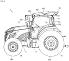
- Fig. 4 is a right side view of the tractor.
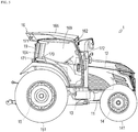
- Fig. 5 is a left side view of the tractor.
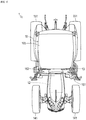
- Fig. 6 is a plan view of the tractor.
- the tractor 1 includes a frame 11, an engine 12, a transmission 13, a front axle 14, and a rear axle 15.
- the frame 11 forms the framework on the front side of the tractor 1.
- the frame 11 constitutes, together with the transmission 13 and the rear axle 15, the chassis of the tractor 1.
- the engine 12 described in the following is supported by the frame 11.
- the engine 12 converts thermal energy obtained by combustion of fuel to kinetic energy. That is, the engine 12 generates rotary power by burning fuel.
- an engine control apparatus is connected to the engine 12 (not shown). In accordance with the operator's operating an acceleration pedal, the engine control apparatus changes the operation state of the engine 12. Further, the engine 12 includes an exhaust gas purification apparatus (not shown). The exhaust gas purification apparatus oxidizes particulates, carbon monoxide, hydrocarbon and the like contained in the exhaust gas.
- the transmission 13 transmits the rotary power of the engine 12 to the front axle 14 and the rear axle 15.
- the transmission 13 receives the rotary power of the engine 12 through a coupling mechanism.
- the transmission 13 includes a continuously variable transmission (HMT or I-HMT). When the operator operates a gear shift lever, the continuously variable transmission changes the operating state of the transmission 13 according to the operator's operation.
- the front axle 14 transmits the rotary power of the engine 12 to front tires 141.
- the front axle 14 receives the rotary power of the engine 12 through the transmission 13.
- a steering apparatus (not shown) is juxtaposed to the front axle 14. When the operator operates a steering wheel, the steering apparatus changes the steering angle of the front tires 141 according to the operator's operation.
- the rear axle 15 transmits the rotary power of the engine 12 to rear tires 151.
- the rear axle 15 receives the rotary power of the engine 12 through the transmission 13.
- the rear axle 15 is provided with a PTO output apparatus 152.
- the PTO output apparatus 152 transmits the rotary power to a towed work machine according to the operator's operation.
- the tractor 1 includes a cabin 16 that protects the operator from wind and weather.
- the cabin 16 has pillars 161 to 164 that are respectively disposed at the four corners, a roof 165 that is substantially rectangular as seen in a plan view and supported by the pillars 161 to 164, and four window panes 166 to 169 respectively provided between adjacent ones of the pillars 161 to 164.
- the inside of the cabin 16 is an operator's compartment where an operator seat 170 and the like are disposed.
- the pillars 161 to 164 consist of two front pillars 161, 162 and two rear pillars 163, 164.
- the front pillars 161, 162 consist of left front pillar 161 and right front pillar 162, and the rear pillars 163, 164 consist of left rear pillar 163 and right rear pillar 164. Note that, the number of the pillars is not limited.
- the left front pillar 161 is curved left-frontward in a convex manner
- the right front pillar 162 is curved right-frontward in a convex manner
- the left rear pillar 163 is curved left-rearward in a convex manner
- the right rear pillar 164 is curved right-rearward in a convex manner.
- the pillars 161 to 164 may be curved outward in a convex manner relative to the cabin 16.
- the condition being curved outward is satisfied by at least the outer surface (the surface positioned outside the vehicle) of the pillars 161 to 164 being curved in any outward direction.
- An inner surface (a surface positioned inside the vehicle) is not necessarily curved outward.
- the roof 165 is mounted on the upper ends of the pillars 161 to 164. As shown in Fig. 6 , in a plan view, the rear pillars 163, 164 are hidden by the roof 165.
- the window panes 166 to 169 consist of a front windshield 166, a rear windshield 167, a left side window pane 168, and a right side window pane 169.
- the window panes 166 to 169 are not specifically limited so long as they are transparent plates capable of transmitting visible light, and they may be made of a transparent resin material such as polycarbonate.
- the left side window pane 168 and the right side window pane 169 have their respective rear ends fixed to the left rear pillar 163 and the right rear pillar 164 with two hinges 171 each.
- the operator can open or close the left side window pane 168 and the right side window pane 169 gripping knobs 172 respectively provided at the front ends of the left side window pane 168 and the right side window pane 169.
- the operator seat 170 is disposed at the center of the cabin 16 or slightly rearward relative to the center of the cabin 16.
- the gear shift lever, the steering wheel, the acceleration pedal, a brake pedal, a clutch pedal, a reverser lever, a speed dial, an instrument panel, a turn signal lamp lever, a light switch, a hazard switch, a work lamp switch and the like are disposed.
- the operator seated on the operator seat 170 can drive the tractor 1 using the acceleration pedal and the like.
- the tractor 1 includes rear lamps 18, 19 respectively provided at the rear pillars 163, 164.
- the rear lamps 18, 19 consist of a left rear lamp 18 provided at the left rear pillar 163 and a right rear lamp 19 provided at the right rear pillar 164.
- the left rear lamp 18 and the right rear lamp 19 are laterally symmetrically shaped and disposed. In order to avoid repetitive descriptions, in the following, a description will be given mainly focusing on the left rear lamp 18, and a detailed description of the right rear lamp 19 will be omitted.
- the left rear lamp 18 is provided along the longitudinal direction (the top-bottom direction) of the left rear pillar 163. This presents an integrated appearance between the left rear lamp 18 and the left rear pillar 163, and hence achieves high designability.
- the left rear lamp 18 is curved along the outer surface of the left rear pillar 163. This enhances the integrated appearance. Note that, so long as the left rear lamp 18 extends along the outer surface of the left rear pillar 163, the left rear lamp 18 is not necessarily curved identically to the left rear pillar 163. For example, the left rear lamp 18 may partially project.
- the left rear lamp 18 is closely in contact with the left rear pillar 163. This also enhances the integrated appearance.
- a clearance may be formed between the left rear lamp 18 and the left rear pillar 163.
- a clearance of a constant width may be formed between the left rear lamp 18 and the left rear pillar 163.
- the left rear lamp 18 is provided from the vicinity of one end (upper end) to the vicinity of the other end (lower end) of the left rear pillar 163 in the longitudinal direction. That is, as seen from the rear side, the left rear pillar 163 is substantially covered with the left rear lamp 18. This enhances the integrated appearance between the left rear lamp 18 and the left rear pillar 163, and achieves high designability. Furthermore, the left rear lamp 18 being elongated in the top-bottom direction provides excellent visibility. Still further, the left rear lamp 18 extending to the vicinity of the roof 165 allows the electrical wiring for the left rear lamp 18 to be arranged through the roof 165 thereby shortening the length of the electrical wiring.
- the length and position of the left rear lamp 18 are not limited so long as the left rear lamp 18 extends along the outer surface of the left rear pillar 163. That is, the left rear lamp 18 is not necessarily provided from the vicinity of one end to the vicinity of the other end of the left rear pillar 163 in the longitudinal direction.
- the left rear lamp 18 may be provided from the vicinity of the center to the vicinity of the other end of the left rear pillar 163 in the longitudinal direction.
- the left rear lamp 18 may be provided from substantial one end to the center of the left rear pillar 163 in the longitudinal direction.
- the left rear lamp 18 may be provided just at the vicinity of the center of the left rear pillar 163 in the longitudinal direction.
- the left rear lamp 18 is formed so as to be hidden by the left rear pillar 163 as seen from the operator on the operator seat (when seated) 170. Therefore, the left rear lamp 18 is designed to have a reduced thickness, and a width narrower than that of the left rear pillar 163. Since the left rear lamp 18 is hidden by the left rear pillar 163 as seen from the operator seated on the operator seat 170, light of the left rear lamp 18 will not come within sight of the operator, thereby avoiding distracting the operator.
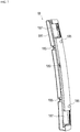
- Figs. 7 to 12 are enlarged views of the left rear lamp.
- Figs. 7 to 11 are illustrations seen from the directions identical to Figs. 2 to 6 , respectively.
- Fig. 12 is a bottom view.
- Fig. 13 is an illustration corresponding to Fig. 8 from which a lens and a lens cover are removed.
- Fig. 14 is an illustration corresponding to Fig. 9 from which the lens and the lens cover are removed.
- Fig. 15 is an illustration corresponding to Fig. 10 from which the lens and the lens cover are removed.
- Fig. 16 is an illustration corresponding to Fig. 11 from which the lens and the lens cover are removed.
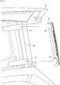
- Fig. 17 is an illustration explaining the positional relationship between the left rear lamp and the left rear pillar.
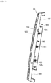
- the left rear lamp 18 includes a lamp housing 181, a light source 182, a lens 183, and a lens cover 184.
- the lamp housing 181 is a box-shaped member that has an opening on the rear side surface, and formed by black-color resin, for example.
- the lamp housing 181 has an attaching surface formed along the left rear pillar 163.
- the outer surface of the rear pillar 163 is curved outward in a convex manner, and the lamp housing 181 is curved along the outer surface of the left rear pillar 163 from the vicinity of the upper end to the vicinity of the lower end of the left rear pillar 163 in the longitudinal direction. This presents an integrated appearance between the lamp housing 181 and the left rear pillar 163, and achieves high designability.
- the lamp housing 181 is screwed to the left rear pillar 163 using four holes 185.
- the lamp housing 181 may be attached by other means such as snaps.
- projections 186 projecting rearward are formed respectively at the vicinity of the upper end and the vicinity of the lower end.
- the opposite surface sides of the projections 186 are recesses 187, where the two hinges 171 of the left side window pane 168 are partially housed (see Fig. 17 ).
- a recess 188 that houses the light source 182 is formed between the projections 186 inside the lamp housing 181, a recess 188 that houses the light source 182 is formed.
- the recess 188 is provided with a hole (not shown) for screwing a substrate of the light source 182.
- the recess 188 is provided with a reflective surface by aluminum deposition or the like. Further, providing a partition inside the lamp housing 181 as appropriate can prevent light leakage from the light source 182. For example, a partition separating the recess 188 and the projections 186 from each other can be provided.
- a through hole 189 for passing an electrical wiring for the light source 182 is formed in the recess 188 of the lamp housing 181.
- the through hole 189 is disposed immediately above the light source 182, and penetrates in the front-rear direction.
- the electrical wiring passes through the roof 165 and the left rear pillar 163, and connected to the light source 182 through a hole provided at the position overlapping the through hole 189 of the left rear pillar 163 and the through hole 189.
- the light source 182 is made up of one substrate and a plurality of red-color LEDs and a plurality of orange-color LEDs mounted on the substrate. In the present embodiment, three LEDs are arranged in line in the right-left direction to lead their respective columns. In each column, red-color LEDs are arranged by six pieces in the top-bottom direction so that the columns form a red-color LED group 182a. In each column, orange-color LEDs are arranged by eleven pieces in the top-bottom direction so that the columns form an orange-color LED group 182b. The orange-color LED group 182b is disposed above the red-color LED group 182a. The red-color LED group 182a serves as a tail lamp and a stop lamp, and the orange-color LED group 182b serves as a turn signal lamp.
- the light source 182 is housed in the recess 188 of the lamp housing 181. As seen from the right and left side surfaces, the LED portion (the light emitting part) projects further than the right and left side surfaces of the lamp housing 181. Thus, a greater amount of light can be extracted to the right and left sides, and visibility from the right and left sides improves.
- employing LEDs as the light source 182 can reduce the thickness of the left rear lamp 18.
- the reduced thickness contributes to realizing the manner of the left rear lamp 18 being hidden by the left rear pillar 163 as seen from the operator seat 170.
- any light source other than LEDs may be employed as the light source 182.
- the rear lamp according to the present embodiment is a rear combination lamp in which three types of lamps (the tail lamp, the stop lamp, and the turn signal lamp) are installed.
- the rear lamp may be embodied as one type of lamp, or a combination of two or four or more types of lamps.
- the lens 183 is a light diffusing member that covers the opening of the lamp housing 181.
- the lens 183 is just required to be a light-transmissive member, and for example may be made of transparent resin.
- the lens 183 covers the entire rear side surface of the lamp housing 181, and partially wraps the top, bottom, right, and left side surfaces. In particular, a portion of the lens 183 that overlaps the right side surface of the light source 182 extends so as to wrap the right side surface of the light source 182.
- the entire rear side surface of the lens 183 is faceted in a grid-like manner, and the top, bottom, right, and left side surfaces of the lens 183 are faceted in a slit-like manner.
- the lens 183 is not limited to such a shape.
- the lens 183 is just required to be disposed at least on the rear side of the light source 182.
- the lens may be provided just at a portion overlapping the light source 182.
- a white-color light source may be employed as the light source 182, and colored lens in red or orange may be employed as the lens 183.
- the lens cover 184 is a light-transmissive member that covers the outer surface of the lens 183.
- the lens cover 184 may be made of transparent resin, for example.
- the lens cover 184 covers the entire rear side surface of the lens 183, and extends longer on part of the top, bottom, right, and left side surfaces of the lamp housing 181 than the lens 183 does.
- the top, bottom, right, and left side surfaces of the lens cover 184 are respectively flush with the top, bottom, right, and left side surfaces of the lamp housing 181, presenting an integrated appearance between the surfaces and the lamp housing 181 and achieving high designability.
- the top, bottom, right, and left side surfaces of the lamp housing 181 are provided with grooves for fitting to the lens cover 184.
- various components can be added in the space in the left rear lamp 18 excluding the light source 182.
- a work lamp, a work machine raise/lower switch, a rear reflector and the like may be provided in the space.
- the work lamp may be provided, for example, in the recess 188 of the lamp housing 181 and above the light source 182.
- the work machine raise/lower switch is normally provided at a rear portion of the rear fender, and includes a button for raising the coupled work machine and a button for lowering the same.
- the work machine raise/lower switch may be provided, for example, at the projections 186 beneath the light source 182 of the lamp housing 181.
- the lens 183 and the lens cover 184 should have a length up to the lower end of the light source 182, so as to avoid interference with the work machine raise/lower switch.
- the rear reflector may be provided, for example, at a position in the rear side surface of the lens 183 or the lens cover 184 where interference with the light source 182 can be avoided.
- the rear reflector can be formed by subjecting the lens 183 or the lens cover 184 to reflection works.
- installing in the left rear lamp 18 the components such as the work lamp, the work machine raise/lower switch, and the rear reflector which have conventionally been provided separately from the rear lamp reduces members separately mounted on the rear side of the tractor 1, and improves designability.
- the present invention is applicable to a work vehicle not including a cabin.
- the present invention is also applicable to a work vehicle including a canopy or a roll bar.
- the rear lamp is provided to a rear pillar positioned behind the operator seat.
- the rear lamp is provided to the rear pillar of the canopy or the rear pillar of the roll bar.
- the present invention is applicable to a work vehicle that at least includes a rear pillar positioned behind the operator seat.
- the shape or function of the rear pillar is not specifically limited.
- the rear pillar may be inverted C-shaped.
- a laterally elongated rear lamp may be provided along the horizontal portion of the rear pillar.
- the rear pillar may not be the rearmost pillar so long as it is positioned behind the operator seat.
- the rear lamp may not be provided in a right and left pair, and the rear lamp may be one in number. Still further, the right and left rear lamps may be asymmetric.
- the present invention is applicable to a work vehicle such as a farm tractor or an earthmoving wheel loader.
Landscapes
- Engineering & Computer Science (AREA)
- Mechanical Engineering (AREA)
- General Engineering & Computer Science (AREA)
- Chemical & Material Sciences (AREA)
- Combustion & Propulsion (AREA)
- Transportation (AREA)
- Lighting Device Outwards From Vehicle And Optical Signal (AREA)
Abstract
Description
- The present invention relates to a work vehicle that includes a rear lamp.
- Conventionally, there have been known work vehicles such as farm tractors (see Patent Document 1) and earthmoving wheel loaders. Such work vehicles generally include rear lamps. The rear lamps include tail lamps, stop lamps, and turn signal lamps.
- In view of the fact that the rear lamps must be disposed at predetermined positions, normally the rear lamps of a work vehicle are mounted as separate members on the upper portions of the rear fenders, for example.
- Patent Document 1:
JP-A 2010-163036 - However, in determining the disposition of the rear lamps, flexibility tends to be limited with a work vehicle having large driving wheels, of which the rear lamps must keep clear. Thus, in some cases, disposing the rear lamps at the predetermined positions reduces designability as seen from the rear side of the work vehicle.
- An object of the present invention is to provide a work vehicle that includes a rear lamp with high designability.
- A work vehicle of the present invention includes a rear lamp, wherein the rear lamp includes a lamp housing that is provided along a longitudinal direction of a rear pillar positioned behind an operator seat, and a light source that is housed in the lamp housing.
- In the work vehicle, the rear lamp may be provided from a vicinity of one end to a vicinity of the other end of the rear pillar in the longitudinal direction.
- The work vehicle may further include a cabin provided with the rear pillar.
- In the work vehicle, an outer surface of the rear pillar may be curved outward in a convex manner, and the lamp housing may be curved along the outer surface of the rear pillar.
- In the work vehicle, the rear lamp may be hidden by the rear pillar as seen from the operator seat.
- In the work vehicle, the light source may constitute a tail lamp, a stop lamp and a turn signal lamp.
- In the work vehicle, the rear lamp may include a lens that covers an opening of the lamp housing.
- In the work vehicle, the rear lamp may include a light-transmissive lens cover that covers an outer surface of the lens.
- In the work vehicle, the rear lamp may be provided with a work lamp.
- In the work vehicle, the rear lamp may be provided with a work machine raise/lower switch.
- In the work vehicle, the rear lamp may be provided with a rear reflector.
- In accordance with the work vehicle of the present invention, the rear lamp is provided along the longitudinal direction of the rear pillar positioned behind the operator seat, resulting in high designability due to an integrated appearance between the rear lamp and the rear pillar.
- In accordance with the work vehicle of the present invention, the rear lamp is provided from the vicinity of one end to the vicinity of the other end of the rear pillar, thereby improving the integrated appearance between the rear lamp and the rear pillar and achieving high designability. Further, the rear lamp extends in the top-bottom direction, resulting in excellent visibility. Still further, the rear lamp extends to the vicinity of a roof, resulting in short electrical wiring for the rear lamp through the roof.
- The work vehicle of the present invention including the cabin provided with the rear pillar is applicable to a tractor including a cabin.
- In accordance with the work vehicle of the present invention, the outer surface of the rear pillar is curved outward in a convex manner and the lamp housing is curved along the outer surface of the rear pillar, resulting in high designability due to an integrated appearance between the lamp housing and the rear pillar.
- In accordance with the work vehicle of the present invention, the rear lamp is hidden by the rear pillar as seen from the operator seat, thereby preventing light of the rear lamp from coming into sight of the operator, which results in smooth operation.
- In accordance with the work vehicle of the present invention, the light source constitutes a tail lamp, a stop lamp and a turn signal lamp, which allows the rear lamp to serve as a rear combination lamp.
- In accordance with the work vehicle of the present invention, the rear lamp includes the lens covering the opening of the lamp housing, resulting in diffusion of light from the light source.
- In accordance with the work vehicle of the present invention, the rear lamp includes the light-transmissive lens cover that covers an outer surface of the lens, thereby improving designability.
- In accordance with the work vehicle of the present invention, the rear lamp is provided with the work lamp, the work machine raise/lower switch or the rear reflector, thereby reducing members separately mounted on the rear portion of the work vehicle and improving designability.
-
-
Fig. 1 is an exterior perspective view of a tractor. -
Fig. 2 is a front view of the tractor. -
Fig. 3 is a rear view of the tractor. -
Fig. 4 is a right side view of the tractor. -
Fig. 5 is a left side view of the tractor. -
Fig. 6 is a plan view of the tractor. -
Fig. 7 is an enlarged front view of a left rear lamp. -
Fig. 8 is an enlarged rear view of the left rear lamp. -
Fig. 9 is an enlarged right side view of the left rear lamp. -
Fig. 10 is an enlarged left side view of the left rear lamp. -
Fig. 11 is an enlarged plan view of the left rear lamp. -
Fig. 12 is an enlarged bottom view of the left rear lamp. -
Fig. 13 is an illustration corresponding toFig. 8 from which a lens and a lens cover are removed. -
Fig. 14 is an illustration corresponding toFig. 9 from which the lens and the lens cover are removed. -
Fig. 15 is an illustration corresponding toFig. 10 from which the lens and the lens cover are removed. -
Fig. 16 is an illustration corresponding toFig. 11 from which the lens and the lens cover are removed. -
Fig. 17 is an illustration explaining the positional relationship between the left rear lamp and a left rear pillar. - The technical idea of the present invention is applicable to any work vehicle such as an agricultural machinery vehicle or a construction machinery vehicle. In the following, a description will be given of a tractor as a representative work vehicle. In the following, the front, rear, upper, lower, right, and left directions refer to those as seen from the operator seat (when the operator is seated).
-
Fig. 1 is a perspective view of a tractor.Fig. 2 is a front view of the tractor.Fig. 3 is a rear view of the tractor.Fig. 4 is a right side view of the tractor.Fig. 5 is a left side view of the tractor.Fig. 6 is a plan view of the tractor. - The
tractor 1 includes aframe 11, anengine 12, atransmission 13, afront axle 14, and arear axle 15. - The
frame 11 forms the framework on the front side of thetractor 1. Theframe 11 constitutes, together with thetransmission 13 and therear axle 15, the chassis of thetractor 1. Theengine 12 described in the following is supported by theframe 11. - The
engine 12 converts thermal energy obtained by combustion of fuel to kinetic energy. That is, theengine 12 generates rotary power by burning fuel. Note that, an engine control apparatus is connected to the engine 12 (not shown). In accordance with the operator's operating an acceleration pedal, the engine control apparatus changes the operation state of theengine 12. Further, theengine 12 includes an exhaust gas purification apparatus (not shown). The exhaust gas purification apparatus oxidizes particulates, carbon monoxide, hydrocarbon and the like contained in the exhaust gas. - The
transmission 13 transmits the rotary power of theengine 12 to thefront axle 14 and therear axle 15. Thetransmission 13 receives the rotary power of theengine 12 through a coupling mechanism. Note that, thetransmission 13 includes a continuously variable transmission (HMT or I-HMT). When the operator operates a gear shift lever, the continuously variable transmission changes the operating state of thetransmission 13 according to the operator's operation. - The
front axle 14 transmits the rotary power of theengine 12 tofront tires 141. Thefront axle 14 receives the rotary power of theengine 12 through thetransmission 13. Note that, a steering apparatus (not shown) is juxtaposed to thefront axle 14. When the operator operates a steering wheel, the steering apparatus changes the steering angle of thefront tires 141 according to the operator's operation. - The
rear axle 15 transmits the rotary power of theengine 12 torear tires 151. Therear axle 15 receives the rotary power of theengine 12 through thetransmission 13. Note that, therear axle 15 is provided with aPTO output apparatus 152. When the operator operates a PTO switch, thePTO output apparatus 152 transmits the rotary power to a towed work machine according to the operator's operation. - Further, the
tractor 1 includes acabin 16 that protects the operator from wind and weather. Thecabin 16 haspillars 161 to 164 that are respectively disposed at the four corners, aroof 165 that is substantially rectangular as seen in a plan view and supported by thepillars 161 to 164, and fourwindow panes 166 to 169 respectively provided between adjacent ones of thepillars 161 to 164. The inside of thecabin 16 is an operator's compartment where anoperator seat 170 and the like are disposed. - The
pillars 161 to 164 consist of twofront pillars rear pillars front pillars front pillar 161 and rightfront pillar 162, and therear pillars rear pillar 163 and rightrear pillar 164. Note that, the number of the pillars is not limited. - As to the
pillars 161 to 164, for example as shown inFigs. 1 to 6 , the leftfront pillar 161 is curved left-frontward in a convex manner; the rightfront pillar 162 is curved right-frontward in a convex manner; the leftrear pillar 163 is curved left-rearward in a convex manner; and the rightrear pillar 164 is curved right-rearward in a convex manner. In this manner, thepillars 161 to 164 may be curved outward in a convex manner relative to thecabin 16. The condition being curved outward is satisfied by at least the outer surface (the surface positioned outside the vehicle) of thepillars 161 to 164 being curved in any outward direction. An inner surface (a surface positioned inside the vehicle) is not necessarily curved outward. - The
roof 165 is mounted on the upper ends of thepillars 161 to 164. As shown inFig. 6 , in a plan view, therear pillars roof 165. - The
window panes 166 to 169 consist of afront windshield 166, arear windshield 167, a leftside window pane 168, and a rightside window pane 169. Note that, thewindow panes 166 to 169 are not specifically limited so long as they are transparent plates capable of transmitting visible light, and they may be made of a transparent resin material such as polycarbonate. The leftside window pane 168 and the rightside window pane 169 have their respective rear ends fixed to the leftrear pillar 163 and the rightrear pillar 164 with twohinges 171 each. Thus, the operator can open or close the leftside window pane 168 and the rightside window pane 169gripping knobs 172 respectively provided at the front ends of the leftside window pane 168 and the rightside window pane 169. - The
operator seat 170 is disposed at the center of thecabin 16 or slightly rearward relative to the center of thecabin 16. Around theoperator seat 170, the gear shift lever, the steering wheel, the acceleration pedal, a brake pedal, a clutch pedal, a reverser lever, a speed dial, an instrument panel, a turn signal lamp lever, a light switch, a hazard switch, a work lamp switch and the like are disposed. The operator seated on theoperator seat 170 can drive thetractor 1 using the acceleration pedal and the like. - Further, the
tractor 1 includesrear lamps rear pillars rear lamps rear lamp 18 provided at the leftrear pillar 163 and a rightrear lamp 19 provided at the rightrear pillar 164. As shown inFig. 3 , the leftrear lamp 18 and the rightrear lamp 19 are laterally symmetrically shaped and disposed. In order to avoid repetitive descriptions, in the following, a description will be given mainly focusing on the leftrear lamp 18, and a detailed description of the rightrear lamp 19 will be omitted. - The left
rear lamp 18 is provided along the longitudinal direction (the top-bottom direction) of the leftrear pillar 163. This presents an integrated appearance between the leftrear lamp 18 and the leftrear pillar 163, and hence achieves high designability. In more detail, the leftrear lamp 18 is curved along the outer surface of the leftrear pillar 163. This enhances the integrated appearance. Note that, so long as the leftrear lamp 18 extends along the outer surface of the leftrear pillar 163, the leftrear lamp 18 is not necessarily curved identically to the leftrear pillar 163. For example, the leftrear lamp 18 may partially project. - Further, the left
rear lamp 18 is closely in contact with the leftrear pillar 163. This also enhances the integrated appearance. Alternatively, a clearance may be formed between the leftrear lamp 18 and the leftrear pillar 163. For example, a clearance of a constant width may be formed between the leftrear lamp 18 and the leftrear pillar 163. - The left
rear lamp 18 is provided from the vicinity of one end (upper end) to the vicinity of the other end (lower end) of the leftrear pillar 163 in the longitudinal direction. That is, as seen from the rear side, the leftrear pillar 163 is substantially covered with the leftrear lamp 18. This enhances the integrated appearance between the leftrear lamp 18 and the leftrear pillar 163, and achieves high designability. Furthermore, the leftrear lamp 18 being elongated in the top-bottom direction provides excellent visibility. Still further, the leftrear lamp 18 extending to the vicinity of theroof 165 allows the electrical wiring for the leftrear lamp 18 to be arranged through theroof 165 thereby shortening the length of the electrical wiring. - Further, the length and position of the left
rear lamp 18 are not limited so long as the leftrear lamp 18 extends along the outer surface of the leftrear pillar 163. That is, the leftrear lamp 18 is not necessarily provided from the vicinity of one end to the vicinity of the other end of the leftrear pillar 163 in the longitudinal direction. For example, the leftrear lamp 18 may be provided from the vicinity of the center to the vicinity of the other end of the leftrear pillar 163 in the longitudinal direction. Conversely, the leftrear lamp 18 may be provided from substantial one end to the center of the leftrear pillar 163 in the longitudinal direction. Further, the leftrear lamp 18 may be provided just at the vicinity of the center of the leftrear pillar 163 in the longitudinal direction. - The left
rear lamp 18 is formed so as to be hidden by the leftrear pillar 163 as seen from the operator on the operator seat (when seated) 170. Therefore, the leftrear lamp 18 is designed to have a reduced thickness, and a width narrower than that of the leftrear pillar 163. Since the leftrear lamp 18 is hidden by the leftrear pillar 163 as seen from the operator seated on theoperator seat 170, light of the leftrear lamp 18 will not come within sight of the operator, thereby avoiding distracting the operator. -
Figs. 7 to 12 are enlarged views of the left rear lamp.Figs. 7 to 11 are illustrations seen from the directions identical toFigs. 2 to 6 , respectively.Fig. 12 is a bottom view.Fig. 13 is an illustration corresponding toFig. 8 from which a lens and a lens cover are removed.Fig. 14 is an illustration corresponding toFig. 9 from which the lens and the lens cover are removed.Fig. 15 is an illustration corresponding toFig. 10 from which the lens and the lens cover are removed.Fig. 16 is an illustration corresponding toFig. 11 from which the lens and the lens cover are removed.Fig. 17 is an illustration explaining the positional relationship between the left rear lamp and the left rear pillar. - The left
rear lamp 18 includes alamp housing 181, alight source 182, alens 183, and alens cover 184. - The
lamp housing 181 is a box-shaped member that has an opening on the rear side surface, and formed by black-color resin, for example. Thelamp housing 181 has an attaching surface formed along the leftrear pillar 163. In the present embodiment, the outer surface of therear pillar 163 is curved outward in a convex manner, and thelamp housing 181 is curved along the outer surface of the leftrear pillar 163 from the vicinity of the upper end to the vicinity of the lower end of the leftrear pillar 163 in the longitudinal direction. This presents an integrated appearance between thelamp housing 181 and the leftrear pillar 163, and achieves high designability. - Further, the
lamp housing 181 is screwed to the leftrear pillar 163 using fourholes 185. Note that, thelamp housing 181 may be attached by other means such as snaps. Inside thelamp housing 181,projections 186 projecting rearward are formed respectively at the vicinity of the upper end and the vicinity of the lower end. The opposite surface sides of theprojections 186 arerecesses 187, where the two hinges 171 of the leftside window pane 168 are partially housed (seeFig. 17 ). Between theprojections 186 inside thelamp housing 181, arecess 188 that houses thelight source 182 is formed. Therecess 188 is provided with a hole (not shown) for screwing a substrate of thelight source 182. Further, therecess 188 is provided with a reflective surface by aluminum deposition or the like. Further, providing a partition inside thelamp housing 181 as appropriate can prevent light leakage from thelight source 182. For example, a partition separating therecess 188 and theprojections 186 from each other can be provided. - Further, in the
recess 188 of thelamp housing 181, a throughhole 189 for passing an electrical wiring for thelight source 182 is formed. The throughhole 189 is disposed immediately above thelight source 182, and penetrates in the front-rear direction. The electrical wiring passes through theroof 165 and the leftrear pillar 163, and connected to thelight source 182 through a hole provided at the position overlapping the throughhole 189 of the leftrear pillar 163 and the throughhole 189. - The
light source 182 is made up of one substrate and a plurality of red-color LEDs and a plurality of orange-color LEDs mounted on the substrate. In the present embodiment, three LEDs are arranged in line in the right-left direction to lead their respective columns. In each column, red-color LEDs are arranged by six pieces in the top-bottom direction so that the columns form a red-color LED group 182a. In each column, orange-color LEDs are arranged by eleven pieces in the top-bottom direction so that the columns form an orange-color LED group 182b. The orange-color LED group 182b is disposed above the red-color LED group 182a. The red-color LED group 182a serves as a tail lamp and a stop lamp, and the orange-color LED group 182b serves as a turn signal lamp. - The
light source 182 is housed in therecess 188 of thelamp housing 181. As seen from the right and left side surfaces, the LED portion (the light emitting part) projects further than the right and left side surfaces of thelamp housing 181. Thus, a greater amount of light can be extracted to the right and left sides, and visibility from the right and left sides improves. - In this manner, employing LEDs as the
light source 182 can reduce the thickness of the leftrear lamp 18. The reduced thickness contributes to realizing the manner of the leftrear lamp 18 being hidden by the leftrear pillar 163 as seen from theoperator seat 170. Note that, any light source other than LEDs may be employed as thelight source 182. - The rear lamp according to the present embodiment is a rear combination lamp in which three types of lamps (the tail lamp, the stop lamp, and the turn signal lamp) are installed. Alternatively, the rear lamp may be embodied as one type of lamp, or a combination of two or four or more types of lamps.
- The
lens 183 is a light diffusing member that covers the opening of thelamp housing 181. Thelens 183 is just required to be a light-transmissive member, and for example may be made of transparent resin. Thelens 183 covers the entire rear side surface of thelamp housing 181, and partially wraps the top, bottom, right, and left side surfaces. In particular, a portion of thelens 183 that overlaps the right side surface of thelight source 182 extends so as to wrap the right side surface of thelight source 182. The entire rear side surface of thelens 183 is faceted in a grid-like manner, and the top, bottom, right, and left side surfaces of thelens 183 are faceted in a slit-like manner. Optimizing the shape or size of the facets, the substrate and the like of thelight source 182 become visually unobtrusive, and hence designability improves. Note that, thelens 183 is not limited to such a shape. Thelens 183 is just required to be disposed at least on the rear side of thelight source 182. For example, the lens may be provided just at a portion overlapping thelight source 182. - Alternatively to the mode described above, a white-color light source may be employed as the
light source 182, and colored lens in red or orange may be employed as thelens 183. - The
lens cover 184 is a light-transmissive member that covers the outer surface of thelens 183. Thelens cover 184 may be made of transparent resin, for example. Thelens cover 184 covers the entire rear side surface of thelens 183, and extends longer on part of the top, bottom, right, and left side surfaces of thelamp housing 181 than thelens 183 does. The top, bottom, right, and left side surfaces of thelens cover 184 are respectively flush with the top, bottom, right, and left side surfaces of thelamp housing 181, presenting an integrated appearance between the surfaces and thelamp housing 181 and achieving high designability. In order to be flush, the top, bottom, right, and left side surfaces of thelamp housing 181 are provided with grooves for fitting to thelens cover 184. - Further, various components can be added in the space in the left
rear lamp 18 excluding thelight source 182. For example, a work lamp, a work machine raise/lower switch, a rear reflector and the like may be provided in the space. - The work lamp may be provided, for example, in the
recess 188 of thelamp housing 181 and above thelight source 182. The work machine raise/lower switch is normally provided at a rear portion of the rear fender, and includes a button for raising the coupled work machine and a button for lowering the same. The work machine raise/lower switch may be provided, for example, at theprojections 186 beneath thelight source 182 of thelamp housing 181. In this case, thelens 183 and thelens cover 184 should have a length up to the lower end of thelight source 182, so as to avoid interference with the work machine raise/lower switch. The rear reflector may be provided, for example, at a position in the rear side surface of thelens 183 or thelens cover 184 where interference with thelight source 182 can be avoided. The rear reflector can be formed by subjecting thelens 183 or thelens cover 184 to reflection works. - As described above, installing in the left
rear lamp 18 the components such as the work lamp, the work machine raise/lower switch, and the rear reflector which have conventionally been provided separately from the rear lamp reduces members separately mounted on the rear side of thetractor 1, and improves designability. - While the cabin is provided in the above-described embodiment, the present invention is applicable to a work vehicle not including a cabin. For example, the present invention is also applicable to a work vehicle including a canopy or a roll bar. In this case also, the rear lamp is provided to a rear pillar positioned behind the operator seat. For example, the rear lamp is provided to the rear pillar of the canopy or the rear pillar of the roll bar. In this manner, the present invention is applicable to a work vehicle that at least includes a rear pillar positioned behind the operator seat. The shape or function of the rear pillar is not specifically limited. For example, the rear pillar may be inverted C-shaped. In this case, a laterally elongated rear lamp may be provided along the horizontal portion of the rear pillar. Further, the rear pillar may not be the rearmost pillar so long as it is positioned behind the operator seat.
- Further, the rear lamp may not be provided in a right and left pair, and the rear lamp may be one in number. Still further, the right and left rear lamps may be asymmetric.
- The present invention is applicable to a work vehicle such as a farm tractor or an earthmoving wheel loader.
-
- 1:
- Tractor (work vehicle)
- 16:
- Cabin
- 18:
- Left rear lamp
- 19:
- Right rear lamp
- 163:
- Left rear pillar
- 164:
- Right rear pillar
- 170:
- Operator seat
- 181:
- Lamp housing
- 182:
- Light source
- 183:
- Lens
- 184:
- Lens cover
Claims (11)
- A work vehicle comprising a rear lamp, wherein
the rear lamp includes:a lamp housing that is provided along a longitudinal direction of a rear pillar positioned behind an operator seat; anda light source that is housed in the lamp housing. - The work vehicle according to claim 1, wherein
the rear lamp is provided from a vicinity of one end to a vicinity of the other end of the rear pillar in the longitudinal direction. - The work vehicle according to claim 1 or 2, further comprising a cabin provided with the rear pillar.
- The work vehicle according to any one of claims 1 to 3, wherein
an outer surface of the rear pillar is curved outward in a convex manner, and
the lamp housing is curved along the outer surface of the rear pillar. - The work vehicle according to any one of claims 1 to 4, wherein the rear lamp is hidden by the rear pillar as seen from the operator seat.
- The work vehicle according to any one of claims 1 to 5, wherein the light source constitutes a tail lamp, a stop lamp and a turn signal lamp.
- The work vehicle according to any one of claims 1 to 6, wherein the rear lamp includes a lens that covers an opening of the lamp housing.
- The work vehicle according to claim 7, wherein the rear lamp includes a light-transmissive lens cover that covers an outer surface of the lens.
- The work vehicle according to any one of claims 1 to 8, wherein the rear lamp is provided with a work lamp.
- The work vehicle according to any one of claims 1 to 9, wherein the rear lamp is provided with a work machine raise/lower switch.
- The work vehicle according to any one of claims 1 to 10, wherein the rear lamp is provided with a rear reflector.
Applications Claiming Priority (2)
| Application Number | Priority Date | Filing Date | Title |
|---|---|---|---|
| JP2014219720A JP2016084095A (en) | 2014-10-28 | 2014-10-28 | Work vehicle |
| PCT/JP2015/079496 WO2016067963A1 (en) | 2014-10-28 | 2015-10-20 | Work vehicle |
Publications (3)
| Publication Number | Publication Date |
|---|---|
| EP3213962A1 true EP3213962A1 (en) | 2017-09-06 |
| EP3213962A4 EP3213962A4 (en) | 2017-11-08 |
| EP3213962B1 EP3213962B1 (en) | 2023-12-06 |
Family
ID=55857304
Family Applications (1)
| Application Number | Title | Priority Date | Filing Date |
|---|---|---|---|
| EP15855556.5A Active EP3213962B1 (en) | 2014-10-28 | 2015-10-20 | Tractor |
Country Status (6)
| Country | Link |
|---|---|
| US (2) | US10562443B2 (en) |
| EP (1) | EP3213962B1 (en) |
| JP (1) | JP2016084095A (en) |
| KR (1) | KR101961051B1 (en) |
| CN (2) | CN110667467A (en) |
| WO (1) | WO2016067963A1 (en) |
Cited By (1)
| Publication number | Priority date | Publication date | Assignee | Title |
|---|---|---|---|---|
| IT202300010302A1 (en) | 2023-05-22 | 2024-11-22 | Amog S R L | VISIBILITY IMPROVEMENT SYSTEM IN WORK VEHICLES |
Families Citing this family (6)
| Publication number | Priority date | Publication date | Assignee | Title |
|---|---|---|---|---|
| EP3476681B1 (en) | 2017-10-26 | 2024-12-04 | Ningbo Geely Automobile Research & Development Co. Ltd. | An autonomous driving vehicle |
| JP7074657B2 (en) * | 2018-12-20 | 2022-05-24 | 株式会社クボタ | Work vehicle |
| JP7159122B2 (en) * | 2019-06-28 | 2022-10-24 | 株式会社クボタ | work vehicle |
| DE202020000304U1 (en) * | 2020-01-24 | 2020-02-05 | Vosla Gmbh | Vehicle body component |
| DE102023129946A1 (en) * | 2023-10-30 | 2025-04-30 | Claas Kommanditgesellschaft auf Aktien mbH | Cabin for an agricultural work vehicle |
| WO2026089209A1 (en) * | 2024-10-24 | 2026-04-30 | 엘에스엠트론 주식회사 | Agricultural tractor |
Family Cites Families (32)
| Publication number | Priority date | Publication date | Assignee | Title |
|---|---|---|---|---|
| JPS5349340Y2 (en) * | 1972-12-29 | 1978-11-27 | ||
| IT8122154V0 (en) | 1981-06-22 | 1981-06-22 | Co Bo S P A | VISUAL SIGNALING DEVICE FOR TRUCKS, TRUCKS AND INDUSTRIAL VEHICLES IN GENERAL. |
| JPS5880337U (en) * | 1981-11-27 | 1983-05-31 | 三菱重工業株式会社 | Forklift combination lamp mounting device |
| JPH01146202A (en) * | 1987-12-01 | 1989-06-08 | Koito Mfg Co Ltd | Vehicle lighting appliance |
| JPH0265655U (en) * | 1988-11-09 | 1990-05-17 | ||
| JPH0676610A (en) * | 1992-08-28 | 1994-03-18 | Iseki & Co Ltd | Combination tail lamps such as tractors |
| US5421416A (en) * | 1993-09-08 | 1995-06-06 | Case Corporation | Hitch assembly control system |
| JP3102263B2 (en) * | 1994-05-10 | 2000-10-23 | 市光工業株式会社 | Vehicle lighting |
| JP3104590B2 (en) * | 1995-10-31 | 2000-10-30 | 株式会社豊田自動織機製作所 | Industrial vehicles |
| US5688036A (en) * | 1996-07-11 | 1997-11-18 | Marshall; Belvin F. | High-mounted truck tail lights |
| JPH1159503A (en) * | 1997-08-25 | 1999-03-02 | Kubota Corp | Tractor with cabin |
| US6352359B1 (en) * | 1998-08-25 | 2002-03-05 | Physical Optics Corporation | Vehicle light assembly including a diffuser surface structure |
| JP3904811B2 (en) * | 2000-08-02 | 2007-04-11 | 株式会社小糸製作所 | Vehicle lighting |
| JP2002087155A (en) * | 2000-09-13 | 2002-03-26 | Komatsu Forklift Co Ltd | Rear combination lamp |
| JP2002216507A (en) * | 2001-01-18 | 2002-08-02 | Stanley Electric Co Ltd | Vehicle lighting |
| US6619824B1 (en) * | 2002-12-26 | 2003-09-16 | Fu-Cheng Hou | Warning strip for automobiles |
| US20040223315A1 (en) * | 2003-03-03 | 2004-11-11 | Toyoda Gosei Co., Ltd. | Light emitting apparatus and method of making same |
| JP2006137228A (en) * | 2004-11-10 | 2006-06-01 | Iseki & Co Ltd | Turn signal lamp of vehicle |
| JP4575175B2 (en) * | 2005-01-13 | 2010-11-04 | ヤンマー株式会社 | Work vehicle |
| US7121687B2 (en) * | 2005-01-25 | 2006-10-17 | Osram Sylvania Inc. | Automotive LED bulb |
| JP2006205764A (en) * | 2005-01-25 | 2006-08-10 | Kubota Corp | Cabin equipment |
| JP4457031B2 (en) * | 2005-03-09 | 2010-04-28 | ヤンマー株式会社 | Self-propelled work vehicle |
| US7621662B1 (en) * | 2006-08-07 | 2009-11-24 | Terry Thomas Colbert | Device and system for emergency vehicle lighting |
| JP5070788B2 (en) * | 2006-09-29 | 2012-11-14 | 井関農機株式会社 | Work vehicle |
| US7850349B2 (en) * | 2007-01-05 | 2010-12-14 | Ford Global Technologies, Llc | Headliner mounted center high mount stop lamp (CHMSL) |
| JP4988436B2 (en) * | 2007-05-28 | 2012-08-01 | 三菱農機株式会社 | Work vehicle |
| JP4203534B1 (en) * | 2008-03-18 | 2009-01-07 | 宏 野口 | Vehicle left turn right turn display device |
| JP5435965B2 (en) | 2009-01-15 | 2014-03-05 | ヤンマー株式会社 | Tractor |
| US8007147B2 (en) * | 2009-05-06 | 2011-08-30 | Yung-Fa Lin | Vehicle door safety warning lamp |
| DE102009032471A1 (en) * | 2009-07-09 | 2011-01-13 | Still Gmbh | Mobile work machine with lighting |
| JP2011148471A (en) * | 2010-01-25 | 2011-08-04 | Iseki & Co Ltd | Cabin of working vehicle |
| CN202101118U (en) | 2011-06-22 | 2012-01-04 | 山河智能装备股份有限公司 | Forklift lighting and signal light-emitting diode (LED) lighting system |
-
2014
- 2014-10-28 JP JP2014219720A patent/JP2016084095A/en active Pending
-
2015
- 2015-10-20 US US15/522,479 patent/US10562443B2/en not_active Expired - Fee Related
- 2015-10-20 WO PCT/JP2015/079496 patent/WO2016067963A1/en not_active Ceased
- 2015-10-20 KR KR1020177013054A patent/KR101961051B1/en active Active
- 2015-10-20 CN CN201911079329.0A patent/CN110667467A/en active Pending
- 2015-10-20 EP EP15855556.5A patent/EP3213962B1/en active Active
- 2015-10-20 CN CN201580059363.5A patent/CN107107814B/en active Active
-
2020
- 2020-01-21 US US16/747,620 patent/US11186221B2/en active Active
Cited By (1)
| Publication number | Priority date | Publication date | Assignee | Title |
|---|---|---|---|---|
| IT202300010302A1 (en) | 2023-05-22 | 2024-11-22 | Amog S R L | VISIBILITY IMPROVEMENT SYSTEM IN WORK VEHICLES |
Also Published As
| Publication number | Publication date |
|---|---|
| CN107107814B (en) | 2019-11-26 |
| EP3213962B1 (en) | 2023-12-06 |
| CN107107814A (en) | 2017-08-29 |
| EP3213962A4 (en) | 2017-11-08 |
| US10562443B2 (en) | 2020-02-18 |
| US20170313239A1 (en) | 2017-11-02 |
| CN110667467A (en) | 2020-01-10 |
| US20200148099A1 (en) | 2020-05-14 |
| WO2016067963A1 (en) | 2016-05-06 |
| KR20170070171A (en) | 2017-06-21 |
| US11186221B2 (en) | 2021-11-30 |
| KR101961051B1 (en) | 2019-03-21 |
| JP2016084095A (en) | 2016-05-19 |
Similar Documents
| Publication | Publication Date | Title |
|---|---|---|
| US11186221B2 (en) | Work vehicle with rear pillar lamp | |
| US9506619B2 (en) | Signaling lamps for motor vehicle | |
| US20140003076A1 (en) | Vehicular lamp and window unit | |
| EP3025937B1 (en) | Work vehicle | |
| JP2014008876A (en) | Vehicular rear panel | |
| CN105408168B (en) | Work vehicle | |
| US20130158792A1 (en) | Meter display device for vehicle and display method thereof | |
| KR101764421B1 (en) | Work Vehicle | |
| EP3908481B1 (en) | Covering device, body part and motor vehicle | |
| EP3162632B1 (en) | Tractor headlight device | |
| EP3028901B1 (en) | Work vehicle | |
| JP2019192432A (en) | Vehicular lighting device, vehicular lighting fixture, window panel with vehicular lighting fixture and on-board display | |
| EP3597991A1 (en) | Automotive light | |
| KR101779014B1 (en) | Work Vehicle | |
| CN217917771U (en) | A post plaque and motor vehicle for motor vehicle | |
| DE102013218706A1 (en) | Headlight unit for motorcycle, has extension that is secured to inner surface side of lens portion, and photo sensor that is arranged between lens portion and extension | |
| JP5767902B2 (en) | Vehicle instrument | |
| CN222905683U (en) | Trunk cover assembly and vehicle | |
| JP5775763B2 (en) | Vehicle instrument | |
| JP5808645B2 (en) | Vehicle instrument | |
| JP2019192433A (en) | Vehicular lighting device, vehicular lighting fixture, window panel with vehicular lighting fixture and on-board display | |
| JP2007216727A (en) | Vehicle lamp | |
| JP2013181971A (en) | Instrument device for vehicle |
Legal Events
| Date | Code | Title | Description |
|---|---|---|---|
| STAA | Information on the status of an ep patent application or granted ep patent |
Free format text: STATUS: THE INTERNATIONAL PUBLICATION HAS BEEN MADE |
|
| PUAI | Public reference made under article 153(3) epc to a published international application that has entered the european phase |
Free format text: ORIGINAL CODE: 0009012 |
|
| STAA | Information on the status of an ep patent application or granted ep patent |
Free format text: STATUS: REQUEST FOR EXAMINATION WAS MADE |
|
| 17P | Request for examination filed |
Effective date: 20170529 |
|
| AK | Designated contracting states |
Kind code of ref document: A1 Designated state(s): AL AT BE BG CH CY CZ DE DK EE ES FI FR GB GR HR HU IE IS IT LI LT LU LV MC MK MT NL NO PL PT RO RS SE SI SK SM TR |
|
| AX | Request for extension of the european patent |
Extension state: BA ME |
|
| RIC1 | Information provided on ipc code assigned before grant |
Ipc: B60Q 1/30 20060101ALI20170927BHEP Ipc: B60Q 1/44 20060101ALI20170927BHEP Ipc: B60Q 1/26 20060101AFI20170927BHEP |
|
| A4 | Supplementary search report drawn up and despatched |
Effective date: 20171010 |
|
| DAV | Request for validation of the european patent (deleted) | ||
| DAX | Request for extension of the european patent (deleted) | ||
| RAP1 | Party data changed (applicant data changed or rights of an application transferred) |
Owner name: YANMAR POWER TECHNOLOGY CO., LTD. |
|
| STAA | Information on the status of an ep patent application or granted ep patent |
Free format text: STATUS: EXAMINATION IS IN PROGRESS |
|
| 17Q | First examination report despatched |
Effective date: 20210618 |
|
| GRAP | Despatch of communication of intention to grant a patent |
Free format text: ORIGINAL CODE: EPIDOSNIGR1 |
|
| STAA | Information on the status of an ep patent application or granted ep patent |
Free format text: STATUS: GRANT OF PATENT IS INTENDED |
|
| INTG | Intention to grant announced |
Effective date: 20221208 |
|
| GRAJ | Information related to disapproval of communication of intention to grant by the applicant or resumption of examination proceedings by the epo deleted |
Free format text: ORIGINAL CODE: EPIDOSDIGR1 |
|
| STAA | Information on the status of an ep patent application or granted ep patent |
Free format text: STATUS: EXAMINATION IS IN PROGRESS |
|
| INTC | Intention to grant announced (deleted) | ||
| GRAP | Despatch of communication of intention to grant a patent |
Free format text: ORIGINAL CODE: EPIDOSNIGR1 |
|
| STAA | Information on the status of an ep patent application or granted ep patent |
Free format text: STATUS: GRANT OF PATENT IS INTENDED |
|
| INTG | Intention to grant announced |
Effective date: 20230621 |
|
| GRAS | Grant fee paid |
Free format text: ORIGINAL CODE: EPIDOSNIGR3 |
|
| GRAA | (expected) grant |
Free format text: ORIGINAL CODE: 0009210 |
|
| STAA | Information on the status of an ep patent application or granted ep patent |
Free format text: STATUS: THE PATENT HAS BEEN GRANTED |
|
| AK | Designated contracting states |
Kind code of ref document: B1 Designated state(s): AL AT BE BG CH CY CZ DE DK EE ES FI FR GB GR HR HU IE IS IT LI LT LU LV MC MK MT NL NO PL PT RO RS SE SI SK SM TR |
|
| REG | Reference to a national code |
Ref country code: GB Ref legal event code: FG4D |
|
| REG | Reference to a national code |
Ref country code: CH Ref legal event code: EP |
|
| REG | Reference to a national code |
Ref country code: DE Ref legal event code: R096 Ref document number: 602015086861 Country of ref document: DE |
|
| REG | Reference to a national code |
Ref country code: IE Ref legal event code: FG4D |
|
| REG | Reference to a national code |
Ref country code: LT Ref legal event code: MG9D |
|
| PG25 | Lapsed in a contracting state [announced via postgrant information from national office to epo] |
Ref country code: GR Free format text: LAPSE BECAUSE OF FAILURE TO SUBMIT A TRANSLATION OF THE DESCRIPTION OR TO PAY THE FEE WITHIN THE PRESCRIBED TIME-LIMIT Effective date: 20240307 |
|
| REG | Reference to a national code |
Ref country code: NL Ref legal event code: MP Effective date: 20231206 |
|
| PG25 | Lapsed in a contracting state [announced via postgrant information from national office to epo] |
Ref country code: LT Free format text: LAPSE BECAUSE OF FAILURE TO SUBMIT A TRANSLATION OF THE DESCRIPTION OR TO PAY THE FEE WITHIN THE PRESCRIBED TIME-LIMIT Effective date: 20231206 |
|
| PG25 | Lapsed in a contracting state [announced via postgrant information from national office to epo] |
Ref country code: ES Free format text: LAPSE BECAUSE OF FAILURE TO SUBMIT A TRANSLATION OF THE DESCRIPTION OR TO PAY THE FEE WITHIN THE PRESCRIBED TIME-LIMIT Effective date: 20231206 |
|
| PG25 | Lapsed in a contracting state [announced via postgrant information from national office to epo] |
Ref country code: LT Free format text: LAPSE BECAUSE OF FAILURE TO SUBMIT A TRANSLATION OF THE DESCRIPTION OR TO PAY THE FEE WITHIN THE PRESCRIBED TIME-LIMIT Effective date: 20231206 Ref country code: GR Free format text: LAPSE BECAUSE OF FAILURE TO SUBMIT A TRANSLATION OF THE DESCRIPTION OR TO PAY THE FEE WITHIN THE PRESCRIBED TIME-LIMIT Effective date: 20240307 Ref country code: ES Free format text: LAPSE BECAUSE OF FAILURE TO SUBMIT A TRANSLATION OF THE DESCRIPTION OR TO PAY THE FEE WITHIN THE PRESCRIBED TIME-LIMIT Effective date: 20231206 Ref country code: BG Free format text: LAPSE BECAUSE OF FAILURE TO SUBMIT A TRANSLATION OF THE DESCRIPTION OR TO PAY THE FEE WITHIN THE PRESCRIBED TIME-LIMIT Effective date: 20240306 |
|
| REG | Reference to a national code |
Ref country code: AT Ref legal event code: MK05 Ref document number: 1638088 Country of ref document: AT Kind code of ref document: T Effective date: 20231206 |
|
| PG25 | Lapsed in a contracting state [announced via postgrant information from national office to epo] |
Ref country code: NL Free format text: LAPSE BECAUSE OF FAILURE TO SUBMIT A TRANSLATION OF THE DESCRIPTION OR TO PAY THE FEE WITHIN THE PRESCRIBED TIME-LIMIT Effective date: 20231206 |
|
| PG25 | Lapsed in a contracting state [announced via postgrant information from national office to epo] |
Ref country code: SE Free format text: LAPSE BECAUSE OF FAILURE TO SUBMIT A TRANSLATION OF THE DESCRIPTION OR TO PAY THE FEE WITHIN THE PRESCRIBED TIME-LIMIT Effective date: 20231206 Ref country code: RS Free format text: LAPSE BECAUSE OF FAILURE TO SUBMIT A TRANSLATION OF THE DESCRIPTION OR TO PAY THE FEE WITHIN THE PRESCRIBED TIME-LIMIT Effective date: 20231206 Ref country code: NO Free format text: LAPSE BECAUSE OF FAILURE TO SUBMIT A TRANSLATION OF THE DESCRIPTION OR TO PAY THE FEE WITHIN THE PRESCRIBED TIME-LIMIT Effective date: 20240306 Ref country code: NL Free format text: LAPSE BECAUSE OF FAILURE TO SUBMIT A TRANSLATION OF THE DESCRIPTION OR TO PAY THE FEE WITHIN THE PRESCRIBED TIME-LIMIT Effective date: 20231206 Ref country code: LV Free format text: LAPSE BECAUSE OF FAILURE TO SUBMIT A TRANSLATION OF THE DESCRIPTION OR TO PAY THE FEE WITHIN THE PRESCRIBED TIME-LIMIT Effective date: 20231206 Ref country code: HR Free format text: LAPSE BECAUSE OF FAILURE TO SUBMIT A TRANSLATION OF THE DESCRIPTION OR TO PAY THE FEE WITHIN THE PRESCRIBED TIME-LIMIT Effective date: 20231206 |
|
| PG25 | Lapsed in a contracting state [announced via postgrant information from national office to epo] |
Ref country code: IS Free format text: LAPSE BECAUSE OF FAILURE TO SUBMIT A TRANSLATION OF THE DESCRIPTION OR TO PAY THE FEE WITHIN THE PRESCRIBED TIME-LIMIT Effective date: 20240406 |
|
| PG25 | Lapsed in a contracting state [announced via postgrant information from national office to epo] |
Ref country code: CZ Free format text: LAPSE BECAUSE OF FAILURE TO SUBMIT A TRANSLATION OF THE DESCRIPTION OR TO PAY THE FEE WITHIN THE PRESCRIBED TIME-LIMIT Effective date: 20231206 Ref country code: AT Free format text: LAPSE BECAUSE OF FAILURE TO SUBMIT A TRANSLATION OF THE DESCRIPTION OR TO PAY THE FEE WITHIN THE PRESCRIBED TIME-LIMIT Effective date: 20231206 |
|
| PG25 | Lapsed in a contracting state [announced via postgrant information from national office to epo] |
Ref country code: SK Free format text: LAPSE BECAUSE OF FAILURE TO SUBMIT A TRANSLATION OF THE DESCRIPTION OR TO PAY THE FEE WITHIN THE PRESCRIBED TIME-LIMIT Effective date: 20231206 |
|
| PG25 | Lapsed in a contracting state [announced via postgrant information from national office to epo] |
Ref country code: SM Free format text: LAPSE BECAUSE OF FAILURE TO SUBMIT A TRANSLATION OF THE DESCRIPTION OR TO PAY THE FEE WITHIN THE PRESCRIBED TIME-LIMIT Effective date: 20231206 Ref country code: SK Free format text: LAPSE BECAUSE OF FAILURE TO SUBMIT A TRANSLATION OF THE DESCRIPTION OR TO PAY THE FEE WITHIN THE PRESCRIBED TIME-LIMIT Effective date: 20231206 Ref country code: RO Free format text: LAPSE BECAUSE OF FAILURE TO SUBMIT A TRANSLATION OF THE DESCRIPTION OR TO PAY THE FEE WITHIN THE PRESCRIBED TIME-LIMIT Effective date: 20231206 Ref country code: IT Free format text: LAPSE BECAUSE OF FAILURE TO SUBMIT A TRANSLATION OF THE DESCRIPTION OR TO PAY THE FEE WITHIN THE PRESCRIBED TIME-LIMIT Effective date: 20231206 Ref country code: IS Free format text: LAPSE BECAUSE OF FAILURE TO SUBMIT A TRANSLATION OF THE DESCRIPTION OR TO PAY THE FEE WITHIN THE PRESCRIBED TIME-LIMIT Effective date: 20240406 Ref country code: EE Free format text: LAPSE BECAUSE OF FAILURE TO SUBMIT A TRANSLATION OF THE DESCRIPTION OR TO PAY THE FEE WITHIN THE PRESCRIBED TIME-LIMIT Effective date: 20231206 Ref country code: CZ Free format text: LAPSE BECAUSE OF FAILURE TO SUBMIT A TRANSLATION OF THE DESCRIPTION OR TO PAY THE FEE WITHIN THE PRESCRIBED TIME-LIMIT Effective date: 20231206 Ref country code: AT Free format text: LAPSE BECAUSE OF FAILURE TO SUBMIT A TRANSLATION OF THE DESCRIPTION OR TO PAY THE FEE WITHIN THE PRESCRIBED TIME-LIMIT Effective date: 20231206 |
|
| PG25 | Lapsed in a contracting state [announced via postgrant information from national office to epo] |
Ref country code: PT Free format text: LAPSE BECAUSE OF FAILURE TO SUBMIT A TRANSLATION OF THE DESCRIPTION OR TO PAY THE FEE WITHIN THE PRESCRIBED TIME-LIMIT Effective date: 20240408 Ref country code: PL Free format text: LAPSE BECAUSE OF FAILURE TO SUBMIT A TRANSLATION OF THE DESCRIPTION OR TO PAY THE FEE WITHIN THE PRESCRIBED TIME-LIMIT Effective date: 20231206 |
|
| PG25 | Lapsed in a contracting state [announced via postgrant information from national office to epo] |
Ref country code: PT Free format text: LAPSE BECAUSE OF FAILURE TO SUBMIT A TRANSLATION OF THE DESCRIPTION OR TO PAY THE FEE WITHIN THE PRESCRIBED TIME-LIMIT Effective date: 20240408 Ref country code: PL Free format text: LAPSE BECAUSE OF FAILURE TO SUBMIT A TRANSLATION OF THE DESCRIPTION OR TO PAY THE FEE WITHIN THE PRESCRIBED TIME-LIMIT Effective date: 20231206 |
|
| REG | Reference to a national code |
Ref country code: DE Ref legal event code: R097 Ref document number: 602015086861 Country of ref document: DE |
|
| PG25 | Lapsed in a contracting state [announced via postgrant information from national office to epo] |
Ref country code: DK Free format text: LAPSE BECAUSE OF FAILURE TO SUBMIT A TRANSLATION OF THE DESCRIPTION OR TO PAY THE FEE WITHIN THE PRESCRIBED TIME-LIMIT Effective date: 20231206 |
|
| PLBE | No opposition filed within time limit |
Free format text: ORIGINAL CODE: 0009261 |
|
| STAA | Information on the status of an ep patent application or granted ep patent |
Free format text: STATUS: NO OPPOSITION FILED WITHIN TIME LIMIT |
|
| PG25 | Lapsed in a contracting state [announced via postgrant information from national office to epo] |
Ref country code: SI Free format text: LAPSE BECAUSE OF FAILURE TO SUBMIT A TRANSLATION OF THE DESCRIPTION OR TO PAY THE FEE WITHIN THE PRESCRIBED TIME-LIMIT Effective date: 20231206 |
|
| PG25 | Lapsed in a contracting state [announced via postgrant information from national office to epo] |
Ref country code: SI Free format text: LAPSE BECAUSE OF FAILURE TO SUBMIT A TRANSLATION OF THE DESCRIPTION OR TO PAY THE FEE WITHIN THE PRESCRIBED TIME-LIMIT Effective date: 20231206 Ref country code: DK Free format text: LAPSE BECAUSE OF FAILURE TO SUBMIT A TRANSLATION OF THE DESCRIPTION OR TO PAY THE FEE WITHIN THE PRESCRIBED TIME-LIMIT Effective date: 20231206 |
|
| 26N | No opposition filed |
Effective date: 20240909 |
|
| REG | Reference to a national code |
Ref country code: DE Ref legal event code: R119 Ref document number: 602015086861 Country of ref document: DE |
|
| REG | Reference to a national code |
Ref country code: CH Ref legal event code: PL |
|
| GBPC | Gb: european patent ceased through non-payment of renewal fee |
Effective date: 20241020 |
|
| PG25 | Lapsed in a contracting state [announced via postgrant information from national office to epo] |
Ref country code: MC Free format text: LAPSE BECAUSE OF FAILURE TO SUBMIT A TRANSLATION OF THE DESCRIPTION OR TO PAY THE FEE WITHIN THE PRESCRIBED TIME-LIMIT Effective date: 20231206 |
|
| PG25 | Lapsed in a contracting state [announced via postgrant information from national office to epo] |
Ref country code: DE Free format text: LAPSE BECAUSE OF NON-PAYMENT OF DUE FEES Effective date: 20250501 |
|
| PG25 | Lapsed in a contracting state [announced via postgrant information from national office to epo] |
Ref country code: GB Free format text: LAPSE BECAUSE OF NON-PAYMENT OF DUE FEES Effective date: 20241020 |
|
| PG25 | Lapsed in a contracting state [announced via postgrant information from national office to epo] |
Ref country code: BE Free format text: LAPSE BECAUSE OF NON-PAYMENT OF DUE FEES Effective date: 20241031 Ref country code: LU Free format text: LAPSE BECAUSE OF NON-PAYMENT OF DUE FEES Effective date: 20241020 |
|
| PG25 | Lapsed in a contracting state [announced via postgrant information from national office to epo] |
Ref country code: FR Free format text: LAPSE BECAUSE OF NON-PAYMENT OF DUE FEES Effective date: 20241031 |
|
| PG25 | Lapsed in a contracting state [announced via postgrant information from national office to epo] |
Ref country code: CH Free format text: LAPSE BECAUSE OF NON-PAYMENT OF DUE FEES Effective date: 20241031 |
|
| REG | Reference to a national code |
Ref country code: BE Ref legal event code: MM Effective date: 20241031 |
|
| PG25 | Lapsed in a contracting state [announced via postgrant information from national office to epo] |
Ref country code: FI Free format text: LAPSE BECAUSE OF FAILURE TO SUBMIT A TRANSLATION OF THE DESCRIPTION OR TO PAY THE FEE WITHIN THE PRESCRIBED TIME-LIMIT Effective date: 20231207 |
|
| PG25 | Lapsed in a contracting state [announced via postgrant information from national office to epo] |
Ref country code: IE Free format text: LAPSE BECAUSE OF NON-PAYMENT OF DUE FEES Effective date: 20241020 |
|
| PG25 | Lapsed in a contracting state [announced via postgrant information from national office to epo] |
Ref country code: CY Free format text: LAPSE BECAUSE OF FAILURE TO SUBMIT A TRANSLATION OF THE DESCRIPTION OR TO PAY THE FEE WITHIN THE PRESCRIBED TIME-LIMIT; INVALID AB INITIO Effective date: 20151020 |
|
| PG25 | Lapsed in a contracting state [announced via postgrant information from national office to epo] |
Ref country code: HU Free format text: LAPSE BECAUSE OF FAILURE TO SUBMIT A TRANSLATION OF THE DESCRIPTION OR TO PAY THE FEE WITHIN THE PRESCRIBED TIME-LIMIT; INVALID AB INITIO Effective date: 20151020 |