EP3213959A1 - Headrest retraction member, and vehicle seat - Google Patents
Headrest retraction member, and vehicle seat Download PDFInfo
- Publication number
- EP3213959A1 EP3213959A1 EP16157973.5A EP16157973A EP3213959A1 EP 3213959 A1 EP3213959 A1 EP 3213959A1 EP 16157973 A EP16157973 A EP 16157973A EP 3213959 A1 EP3213959 A1 EP 3213959A1
- Authority
- EP
- European Patent Office
- Prior art keywords
- headrest
- backrest
- locking member
- vehicle seat
- cable pull
- Prior art date
- Legal status (The legal status is an assumption and is not a legal conclusion. Google has not performed a legal analysis and makes no representation as to the accuracy of the status listed.)
- Granted
Links
- 230000006835 compression Effects 0.000 description 15
- 238000007906 compression Methods 0.000 description 15
- 238000006073 displacement reaction Methods 0.000 description 9
- 230000009471 action Effects 0.000 description 3
- 230000004048 modification Effects 0.000 description 3
- 238000012986 modification Methods 0.000 description 3
- 238000011017 operating method Methods 0.000 description 2
- 230000008901 benefit Effects 0.000 description 1
- 238000010276 construction Methods 0.000 description 1
- 230000006870 function Effects 0.000 description 1
- 230000007246 mechanism Effects 0.000 description 1
- 230000006386 memory function Effects 0.000 description 1
- 230000002040 relaxant effect Effects 0.000 description 1
- 230000007704 transition Effects 0.000 description 1
Images



Classifications
-
- B—PERFORMING OPERATIONS; TRANSPORTING
- B60—VEHICLES IN GENERAL
- B60N—SEATS SPECIALLY ADAPTED FOR VEHICLES; VEHICLE PASSENGER ACCOMMODATION NOT OTHERWISE PROVIDED FOR
- B60N2/00—Seats specially adapted for vehicles; Arrangement or mounting of seats in vehicles
- B60N2/02—Seats specially adapted for vehicles; Arrangement or mounting of seats in vehicles the seat or part thereof being movable, e.g. adjustable
- B60N2/20—Seats specially adapted for vehicles; Arrangement or mounting of seats in vehicles the seat or part thereof being movable, e.g. adjustable the back-rest being tiltable, e.g. to permit easy access
-
- B—PERFORMING OPERATIONS; TRANSPORTING
- B60—VEHICLES IN GENERAL
- B60N—SEATS SPECIALLY ADAPTED FOR VEHICLES; VEHICLE PASSENGER ACCOMMODATION NOT OTHERWISE PROVIDED FOR
- B60N2/00—Seats specially adapted for vehicles; Arrangement or mounting of seats in vehicles
- B60N2/80—Head-rests
- B60N2/806—Head-rests movable or adjustable
- B60N2/809—Head-rests movable or adjustable vertically slidable
- B60N2/832—Head-rests movable or adjustable vertically slidable movable to an inoperative or stowed position
- B60N2/835—Head-rests movable or adjustable vertically slidable movable to an inoperative or stowed position specially adapted for rear seats
-
- B—PERFORMING OPERATIONS; TRANSPORTING
- B60—VEHICLES IN GENERAL
- B60N—SEATS SPECIALLY ADAPTED FOR VEHICLES; VEHICLE PASSENGER ACCOMMODATION NOT OTHERWISE PROVIDED FOR
- B60N2/00—Seats specially adapted for vehicles; Arrangement or mounting of seats in vehicles
- B60N2/005—Arrangement or mounting of seats in vehicles, e.g. dismountable auxiliary seats
- B60N2002/0055—Arrangement or mounting of seats in vehicles, e.g. dismountable auxiliary seats characterised by special measures to ensure that no seat or seat part collides, during its movement, with other seats, seat parts or the vehicle itself
Definitions
- the invention relates to a headrest retraction member for transferring a headrest of a vehicle seat from a position for use into a non-use position, the headrest retraction member having a movably supported locking member which can be moved into and out of engagement with at least one notch of at least one headrest rod of the headrest, and a movably supported actuation component which has a wedge face, wherein, in the event of a movement of the actuation component, the wedge face acts on the locking member in such a manner that the locking member and the at least one notch move out of engagement.
- the invention further relates to a vehicle seat.
- DE 100 05 817 A1 discloses a mechanical headrest retraction member which prevents a collision of a headrest with the roof or a sunshade of a vehicle when the backrest is pivoted forwards, by the headrest, when the headrest is pivoted forwards from a position for use, being transferred into a non-use position.
- the mechanical headrest retraction member can be actuated by means of a cable pull.
- the cable pull connects a folding mechanism which connects a seat member and a backrest in a pivotable manner to a tooth segment of the headrest retraction member.
- An object of the invention is to improve a headrest retraction member of the type mentioned in the introduction, in particular to provide a headrest retraction member having a reduced number of components.
- a corresponding vehicle seat is intended to be provided.
- a headrest retraction member for moving a headrest of a vehicle seat from a position for use into a non-use position
- the headrest retraction member having a movably supported locking member which can be moved into and out of engagement with at least one notch of at least one headrest rod of the headrest, and a movably supported actuation component which has a wedge face, wherein, with a movement of the actuation component, the wedge face acts on the locking member in such a manner that the locking member and the at least one notch move out of engagement, wherein the actuation component is coupled to a cable pull.
- the headrest retraction member may comprise only a few components.
- a first end of the cable pull is directly connected to the actuation component, that is to say, without additional components being interposed.
- the feature "directly connected” is also intended to be understood to mean the connection of the cable pull by means of a securing component which is secured to a cable pull end, preferably a soldered cable pull fitting.
- a second end of the cable pull may be able to be connected to a fitting in order to pivotably support a backrest of the vehicle seat.
- the second end of the cable pull may be connected to the fitting.
- the second end of the cable pull is connected to a component which can be moved relative to a backrest of the vehicle seat so that, when the fitting is actuated or when the backrest is pivoted, there is necessarily a pulling action at the second end of the cable pull.
- a second end of the cable pull may be able to be connected to an operating lever.
- the operating lever may serve to actuate the fitting.
- the second end of the cable pull may be connected to the operating lever so that, when the operating lever is actuated, there is necessarily a pulling action at the second end of the cable pull.
- a second end of the cable pull may be able to be connected to a structural component of a seat member of the vehicle seat.
- the second end of the cable pull may be connected to the structural component of a seat member.
- the backrest can preferably be pivoted relative to the seat member so that, when the backrest is pivoted, there is necessarily a pulling action at the second end of the cable pull.
- an actuation of the cable pull results in the actuation component being moved.
- the cable pull may pull on the actuation component.
- the cable pull may displace the actuation component.
- the cable pull may pivot the actuation component.
- a bridge for connecting to an end region of the at least one headrest rod, in particular for connecting two end regions of two headrest rods of the headrest, affords the advantage that the headrest can be moved by moving the bridge.
- the actuation component may be a sliding member.
- the sliding member may be displaceably guided in a guiding profile.
- the sliding member can preferably be displaced in a direction which is arranged perpendicularly relative to a movement direction of the locking member.
- the locking member in an upright position of the backrest, can be displaced parallel with a transverse direction and the sliding member can be displaced substantially parallel with a vertical direction.
- the sliding member can preferably be displaced radially relative to the backrest pivot axis.
- the cable pull can be connected at least indirectly to the headrest in such a manner that, by means of an actuation of the cable pull, the cable pull pulls the headrest out of the position for use into the non-use position so that an actuation of the cable pull not only unlocks the headrest but subsequently also moves it into the non-use position.
- the movement of the headrest is carried out only after a free travel has been carried out so that the headrest is first completely unlocked before a movement of the headrest is carried out by the cable pull.
- a wedge face of the sliding member preferably initially acts on the locking member in such a manner that the locking member and the at least one notch move out of engagement. Subsequently, the sliding member can also carry the bridge in the direction of the non-use position of the headrest.
- an energy accumulator in particular a tension spring, can move the headrest from the position for use into the non-use position as soon as the locking member and the at least one notch are out of engagement.
- the actuation component may be a rocker arm.
- the rocker arm may be rotatably supported relative to a backrest structure of the vehicle seat.
- the rocker arm may be pivotably supported.
- a pivotable support is distinguished by a high level of operational reliability.
- the rocker arm may be pretensioned by means of a spring, in particular a torsion spring, in such a manner that the rocker arm moves the headrest at least indirectly out of the position for use into the non-use position as soon as the locking member and the at least one notch are out of engagement.
- a spring in particular a torsion spring
- a vehicle seat in particular a motor vehicle seat, having a backrest, a seat member and a headrest, wherein the headrest can be moved by means of a headrest retraction member according to the invention from a position for use into a non-use position.
- the backrest can preferably be pivotably supported about a backrest pivot axis by means of at least one fitting.
- a second end of the cable pull can be connected to a component of the fitting, which component can be moved relative to the backrest.
- the component of the fitting which can be moved relative to the backrest may be a lower fitting member which is connected to the seat member or a component of the fitting, which component is moved during an unlocking operation of the fitting, for example, a carrier.
- the second end of the cable pull may be connected to an operating lever, in particular for actuating the fitting.
- the headrest has two headrest rods which are each movably guided in a sleeve, wherein the two sleeves are securely connected to a backrest structure of the vehicle seat.
- a longitudinal direction x extends in a vehicle seat 1 which is installed in the vehicle in a substantially horizontal manner and preferably parallel with a vehicle longitudinal direction, which corresponds to the conventional travel direction of the vehicle.
- a transverse direction y which extends perpendicularly to the longitudinal direction x is also orientated horizontally in the vehicle and extends parallel with a vehicle transverse direction.
- a vertical direction z extends perpendicularly to the longitudinal direction x and perpendicularly to the transverse direction y. With a vehicle seat 1 which is installed in the vehicle, the vertical direction z extends parallel with the vertical axis of the vehicle.
- the positional and directional indications used such as, for example, front, rear, upper and lower refer to a viewing direction of an occupant sitting in the vehicle seat 1 in a normal seating position, wherein the vehicle seat 1 is installed in the vehicle, is in a position for use which is suitable for transporting passengers with an upright backrest and is orientated in conventional manner in the travel direction.
- the vehicle seat 1 according to the invention can also be installed in a different orientation, for example, transversely relative to the travel direction.
- the vehicle seat 1 has a backrest 10, a seat member 20 and a headrest 110, 210, 310 which is arranged on the backrest 10.
- the backrest 10 has a supporting backrest structure 12 and an upholstery 14.
- the backrest 10 can be pivoted relative to the seat member 20 about a backrest pivot axis A which extends in the transverse direction y and which is defined by a fitting 30 and a rotary bearing.
- the fitting 30 can be unlocked by means of an operating lever 32 which is operationally connected to the fitting 30 so that the backrest 10 can be pivoted forwards out of the position for use about a backrest pivot axis A into the non-use position.
- the headrest 110, 210, 310 is retracted by means of a headrest retraction member 100, 200, 300 according to the invention from a position for use into a non-use position.
- the fitting 30 comprises a first fitting member and a second fitting member which can be rotated relative to the fitting 30 about the backrest pivot axis A when the fitting 30 is unlocked.
- the first fitting member is securely connected to the structure of the seat member 20, that is to say, so as to be fixed to the seat member.
- the second seat member is securely connected to the backrest structure 12 of the backrest 10, that is to say, so as to be fixed to the backrest.
- the fitting 30 may be constructed as a catch fitting, as known, for example, from DE 10 2009 041 492 A1 .
- FIGs 2 to 9 show as a first embodiment a headrest retraction member 100.
- the headrest 110 has two headrest rods 112 which in the position for use of the backrest 10 extend substantially parallel with the vertical direction z, in particular radially with respect to the backrest pivot axis A.
- the two headrest rods 112 have in this instance a round cross-section.
- the two headrest rods 112 carry an upholstered headrest body 111 for supporting a head of an occupant of the vehicle seat 1.
- the ends of the headrest rods 112 facing away from the headrest body 111 are connected to each other by means of a bridge 114.
- the bridge 114 has an elongate form and is orientated parallel with the transverse direction y.
- Each of two end regions of the bridge 114 is securely connected to an end of a headrest rod 112.
- Two sleeves 116 are securely connected to the backrest structure 12 and serve to support the two headrest rods 112.
- Each of the two headrest rods 112 is displaceably guided in one of the two sleeves 116.
- the two headrest rods 112 each have a notch 118.
- the notches 118 cooperate with a locking member 120 of the headrest retraction member 100.
- the locking member 120 is movably supported parallel with the transverse direction y relative to the backrest structure 12. The locking member 120 can be moved into and out of engagement with the notches 118 of the headrest rod 112 in a manner described below in greater detail.
- the structure and the operating method of the headrest retraction member 100 can be seen in Figures 4 to 9 .
- the headrest retraction member 100 has the locking member 120, a guiding portion 130, a sliding member 140 as an actuation component, a guiding profile 150 and a Bowden cable 160.
- the guiding portion 130 can be connected to the backrest structure 12 and, in the mounted state of the vehicle seat 1, is securely connected to the backrest structure 12, for example, screwed.
- the guiding portion 130 has an elongate extent parallel with the transverse direction y.
- the guiding portion 130 supports the locking member 120 movably parallel with the transverse direction y and relative to the backrest structure 12.
- the guiding portion 130 has a substantially C-shaped cross-section with two members extending parallel.
- the members have, at the sides thereof facing each other, a plurality of ribs 132 which are arranged beside each other in the transverse direction y and which are orientated parallel with the vertical direction z.
- a rib 132 of a first member and a rib 132 of the second member of the guiding portion 130 are opposite each other, are arranged with a small spacing with respect to each other and between them receive the locking member 120 in such a manner that the locking member 120 is movably supported parallel with the transverse direction y in the guiding portion 130.
- the locking member 120 has an elongate and substantially planar base member, from which in the end regions an L-shaped hook 124 protrudes downwards in each case. An end of the locking member 120 can be moved by means of a displacement of the locking member 120 into and out of engagement with the notch 118 of one of the headrest rods 112. The other of the two headrest rods 112 extends through an opening in the base member of the locking member 120 in such a manner that an edge of the opening can be brought into and out of engagement with the notch 118 of this headrest rod 112. The locking member 120 is pretensioned by means of a second compression spring 172 in the direction of the notches 118.
- the locking member 120 can fall into the notches 118, and thereby lock the relative position of the headrest rods 112 relative to the backrest structure 12, only if the headrest 110 is located on the position for use. In a locking position of the locking member 120, the two hooks 124 engage below the bridge 114 and thereby additionally secure the position of the headrest 110.
- the locking member 120 has an additional opening whose edge has a contact region 122 and in which the sliding member 140 can engage.
- the sliding member 140 is displaceably guided in the guiding profile 150 parallel with the headrest rods 112.
- the guiding profile 150 is secured to the guiding portion 130 and/or the backrest structure 12.
- the sliding member 140 is arranged above the bridge 114 and is supported via a first compression spring 171 on the bridge 114 in such a manner that, in a non-actuated state of the headrest retraction member 100, the sliding member 140 and the bridge 114 are slightly spaced apart from each other.
- the sliding member 140 has a first wedge face 142 and a second wedge face 144.
- the first wedge face 142 In the locked position for use of the headrest 110, the first wedge face 142 is in contact with the contact region 122.
- the first wedge face 142 is arranged in such a manner that a movement of the sliding member 140 in a downward direction leads to a displacement of the locking member 120 in the transverse direction y so that the locking member 120 and the notches 118 move out of engagement.
- the Bowden cable 160 has a cable pull 162 and a sheath 164.
- the Bowden cable 160 connects the sliding member 140 to a component of the fitting 30, which component can be moved relative to the backrest 10, for example, the first fitting member which is connected to the structure of the seat member 20.
- the Bowden cable 160 connects the sliding member 140 to the operating lever 32.
- the sheath 164 is supported, on the one hand, on the guiding profile 150.
- An end of the cable pull 162 is connected to the sliding member 140. To this end, the end of the cable pull 162 is preferably provided with a fitting which is suspended in a slot of the sliding member 140. The other end is connected to the component of the fitting 30, which component can be moved relative to the backrest 10.
- the cable pull 162 first pulls the sliding member 140 with pretensioning of the first compression spring 171 downwards until the sliding member 140 is in abutment with the bridge 114.
- the locking member 120 is displaced by the first wedge face 142 so that the locking member 120 and the notches 118 move out of engagement and the headrest 110 is thereby no longer locked relative to the backrest structure 12.
- the sliding member 140 is moved further downwards by means of the cable pull 162 and is released from the locking member 120.
- the bridge 114 and consequently the headrest 110 is also moved until the sliding member 140 moves into an end stop, preferably on the guiding profile 150.
- the position of the sliding member 140 then corresponds to the non-use position of the headrest 110.
- the headrest 110 can be moved manually again into the position for use thereof.
- the bridge 114 in this instance also carries the sliding member 140 upwards.
- the second wedge face 144 of the sliding member 140 in this instance moves initially into contact with the contact region 122 of the locking member 120 and displaces it slightly in the opening direction. Subsequently, the second wedge face 144 passes the contact region 122 of the locking member 120 until the contact region 122 again moves into abutment with the first wedge face 142 and the first compression spring 171 relaxes.
- the second compression spring 172 presses the locking member 120 again in the direction of the notches 118 so that the locking member 120 again moves into engagement with the notches 118 as soon as the position for use of the headrest 110 is reached.
- Figures 10 to 13 show as a second embodiment a headrest retraction member 200.
- Figures 10 and 11 show the arrangement of a headrest 210 and the headrest retraction member 200 on the backrest 10 of the vehicle seat 1.
- the headrest 210 has two headrest rods 212 which extend in the position for use of the backrest 10 substantially parallel with the vertical direction z, in particular radially relative to the backrest pivot axis A.
- the two headrest rods 212 in this instance have a round cross-section.
- the two headrest rods 212 carry an upholstered headrest body 211 for supporting a head of an occupant of the vehicle seat 1.
- the ends of the headrest rods 212 facing away from the headrest body 211 are connected to each other by means of a bridge 214.
- the bridge 214 has an elongate form and is orientated parallel with the transverse direction y. Each of two end regions of the bridge 214 is securely connected to an end of a headrest rod 212.
- the bridge 214 is pretensioned by means of an energy accumulator which is constructed in this instance as a tension spring 273 in the direction of the non-use position of the headrest 210. An end of the tension spring 273 is connected to the bridge 214. The other end of the tension spring 273 is connected to the backrest structure 12.
- the headrest 210 is in the position for use and the tension spring 273 is tensioned.
- the headrest 210 is in the non-use position and the tension spring 273 is substantially relaxed and concealed in Figure 11 by the bridge 214 and therefore cannot be seen.
- Two sleeves 216 are securely connected to the backrest structure 12 and serve to support the two headrest rods 212. Each of the two headrest rods 212 is displaceably guided in one of the two sleeves 216.
- Both headrest rods 212 each have a notch 218.
- the notches 218 cooperate with a locking member 220 of the headrest retraction member 200.
- the locking member 220 is movably supported parallel with the transverse direction y relative to the backrest structure 12. The locking member 220 can be moved into and out of engagement with the notches 218 of the headrest rod 212 in a manner which is described in greater detail below.
- the structure and operating method of the headrest retraction member 200 correspond, unless otherwise described below, to the first embodiment and can be seen in Figures 12 and 13 .
- the headrest retraction member 200 has the locking member 220, a guiding portion 230, a sliding member 240 as an actuation component, a guiding profile 250, a Bowden cable 260 and the tension spring 273.
- the guiding portion 230 can be connected to the backrest structure 12 and in the mounted state of the vehicle seat 1 is securely connected to the backrest structure 12, for example, screwed.
- the guiding portion 230 has an elongate extent parallel with the transverse direction y.
- the guiding portion 230 supports the locking member 220 in a movable manner parallel with the transverse direction y and relative to the backrest structure 12.
- the guiding portion 230 has a substantially C-shaped cross-section with two parallel members.
- the members have at the sides thereof which face each other a plurality of ribs 232 which are arranged beside each other in the transverse direction y and which are each orientated parallel with the vertical direction z.
- the locking member 220 has an elongate and substantially planar base member from which in the end regions an L-shaped hook 224 protrudes downwards in each case. An end of the locking member 220 can be moved into and out of engagement with the notch 218 of one of the headrest rods 212 by means of a displacement of the locking member 220. The other of the two headrest rods 212 extends through an opening in the base member of the locking member 220 in such a manner that an edge of the opening can be moved into and out of engagement with the notch 218 of this headrest rod 212.
- the locking member 220 is pretensioned by means of a second compression spring 272 in the direction of the notches 218.
- the locking member 220 can fall into the notches 218, and thereby lock the relative position of the headrest rods 212 relative to the backrest structure 12, only when the headrest 210 is in the position for use. In the locking position of the locking member 220, the two hooks 224 engage below the bridge 214 and thereby additionally secure the position of the headrest 210.
- the locking member 220 has an additional opening whose edge has a contact region 222 and in which the sliding member 240 can engage.
- the sliding member 240 is displaceably guided in the guiding profile 250 parallel with the headrest rods 212.
- the guiding profile 250 is secured to the guiding portion 230 and/or the backrest structure 12.
- the sliding member 240 is arranged above the bridge 214 and is supported via a first compression spring 271 on the bridge 214 in such a manner that, in an inactivated state of the headrest retraction member 200, the sliding member 240 and the bridge 214 are slightly spaced apart from each other.
- the sliding member 240 has a first wedge face 242 and a second wedge face 244. In the locked position for use of the headrest 210, the first wedge face 242 is in contact with the contact region 222.
- the first wedge face 242 is arranged in such a manner that a movement of the sliding member 240 in a downward direction leads to a displacement of the locking member 220 in the transverse direction y so that the locking member 220 and the notches 218 move out of engagement.
- the Bowden cable 260 has a cable pull 262 and a sheath 264.
- the Bowden cable 260 connects the sliding member 240 to a component of the fitting 30, which component can be moved relative to the backrest 10, for example, the first fitting member which is connected to the structure of the seat member 20.
- the Bowden cable 260 connects the sliding member 240 to the operating lever 32.
- the sheath 264 is supported, on the one hand, on the guiding profile 250.
- An end of the cable pull 262 is connected to the sliding member 240. To this end, the end of the cable pull 262 is preferably provided with a fitting which is suspended in a slot of the sliding member 240. The other end is connected to the component of the fitting 30 movable relative to the backrest 10.
- the cable pull 262 pulls the sliding member 240 with pretensioning of the first compression spring 271 downwards until the sliding member 240 is in abutment with the bridge 214.
- the locking member 220 is displaced by the first wedge face 242 so that the locking member 220 and the notches 218 move out of engagement and the headrest 210 is thereby no longer locked relative to the backrest structure 12.
- the bridge 214 is pulled downwards by the tension spring 273. The sliding member 240 is thereby released from the locking member 220.
- the bridge 214 and consequently the headrest 210 are moved downwards by the relaxing tension spring 273 until the sliding member 240 moves into an end stop, preferably on the guiding profile 250.
- the position of the sliding member 240 then corresponds to the non-use position of the headrest 210.
- the headrest 210 can again be manually moved into the position for use thereof with tensioning of the tension spring 273.
- the bridge 214 also carries the sliding member 240 upwards.
- the second wedge face 244 of the sliding member 240 initially moves into contact with the contact region 222 of the locking member 220 and displaces it slightly in the opening direction.
- the second wedge face 244 subsequently passes the contact region 222 of the locking member 220 until the contact region 222 is again in abutment with the first wedge face 242 and the first compression spring 271 relaxes.
- the second compression spring 272 presses the locking member 220 again in the direction of the notches 218 so that the locking member 220 again moves into engagement with the notches 218 as soon as the position for use of the headrest 210 has been reached.
- Figures 14 to 19 show as a third embodiment a headrest retraction member 300.
- Figures 14 and 15 show the arrangement of a headrest 310 and the headrest retraction member 300 on the backrest 10 of the vehicle seat 1.
- the headrest 310 has two headrest rods 312, which extend in the position for use of the backrest 10 substantially parallel with the vertical direction z, in particular radially with respect to the backrest pivot axis A.
- the two headrest rods 312 in this instance have a round cross-section.
- the two headrest rods 312 carry an upholstered headrest body 311 for supporting a head of an occupant of the vehicle seat 1.
- the ends of the headrest rods 312 facing away from the headrest body 311 are connected to each other by means of a bridge 314.
- the bridge 314 has an elongate form and is orientated parallel with the transverse direction y. Each of two end regions of the bridge 314 is securely connected to an end of a headrest rod 312.
- Two sleeves 316 are securely connected to the backrest structure 12 and serve to support the two headrest rods 312. Each of the two headrest rods 312 is displaceably guided in one of the two sleeves 316.
- Both headrest rods 312 have a notch 318.
- the notches 318 cooperate with a locking member 320 of the headrest retraction member 300.
- the locking member 320 is movably supported parallel with the transverse direction y relative to the backrest structure 12. The locking member 320 can be moved into and out of engagement with the notches 318 of the headrest rod 312 in a manner which is described in greater detail below.
- the headrest retraction member 300 has the locking member 320, a guiding member 330, a rocker arm 380 as an actuation component, a redirection segment 390 and a Bowden cable 360.
- the guiding portion 330 can be connected to the backrest structure 12 and, in the assembled state of the vehicle seat 1, is securely connected to the backrest structure 12, for example, screwed.
- the guiding portion 330 has an elongate extent parallel with the transverse direction y.
- the guiding portion 330 supports the locking member 320 in a movable manner parallel with the transverse direction y and relative to the backrest structure 12.
- the guiding portion 330 has a substantially C-shaped cross-section having two members which extend in a parallel manner. The members have at the sides thereof facing each other a plurality of ribs 332 which are arranged beside each other in the transverse direction y and which are each orientated parallel with the vertical direction z.
- the locking member 320 has an elongate and substantially planar base member from which an L-shaped hook 324 protrudes downwards in the end regions. An end of the locking member 320 can be moved into and out of engagement with the notch 318 of one of the headrest rods 312 by means of a displacement of the locking member 320. The other of the two headrest rods 312 extends through an opening in the base member of the locking member 320 in such a manner that an edge of the opening can be moved into and out of engagement with the notch 318 of this headrest rod 312.
- the locking member 320 is pretensioned in the direction of the notches 318 by means of a compression spring which is not illustrated in the Figures.
- the locking member 320 can fall into the notches 318, and thereby lock the relative position of the headrest rods 312 relative to the backrest structure 12, only when the headrest 310 is located in the position for use. In the locking position of the locking member 320, the two hooks 324 engage below the bridge 314 and thereby additionally secure the position of the headrest 310.
- the locking member 320 has an additional opening whose edge has a contact region 322 and in which a finger 382 of the rocker arm 380 can engage, which finger 382 has a first wedge face 342 and a second wedge face 344.
- the rocker arm 380 has an elongate base member.
- the finger 382 is arranged slightly off-centre between two ends of the rocker arm 380.
- the finger 382 protrudes perpendicularly upwards from the base member of the rocker arm 380.
- the finger 382 is in this instance constructed integrally with the base member of the rocker arm 380.
- An end of the rocker arm 380 has a bearing aperture 384 for rotatable support of the rocker arm 380.
- the bearing aperture 384 is supported on a pin 388.
- the pin 388 is secured to the backrest structure 12, for example, screwed or welded.
- a cam 386 which can be positioned at the top on the bridge 314.
- a torsion spring which is not illustrated in the Figures pretensions the rocker arm 380 in such a manner that the cam 386 is acted on in the direction of the bridge 314.
- the redirection segment 390 has the basic form of a circle sector.
- the redirection segment 390 is securely connected to the backrest structure 12 by means of a screw 392.
- the Bowden cable 360 has a cable pull 362 and a sheath 364.
- the Bowden cable 360 connects the rocker arm 380 to a component of the fitting 30, which component can be moved relative to the backrest 10, for example, the first fitting member which is connected to the structure of the seat member 20.
- the Bowden cable 360 connects the rocker arm 380 to the operating lever 32.
- the sheath 364 is supported at one side on the redirection segment 390.
- An end of the cable pull 362 is guided via the redirection segment 390 and connected to the rocker arm 380.
- the end of the cable pull 362 is preferably provided with a fitting, which is suspended in a slot of the rocker arm 380. The other end is connected to the component of the fitting 30, which component can be moved relative to the backrest 10.
- the first wedge face 342 In the locked position for use of the headrest 310, the first wedge face 342 is in contact with the contact region 322.
- the first wedge face 342 is arranged in such a manner that a pivot movement of the rocker arm 380 and consequently the finger 382 in a downward direction leads to a displacement of the locking member 320 in a transverse direction y so that the locking member 320 and the notches 318 move out of engagement.
- the bridge 314 is pivoted downwards by the torsion spring 273. The finger 382 is thereby released from the locking member 320.
- the bridge 314 and consequently the headrest 310 are moved downwards by the rocker arm 380 which is accordingly pretensioned by the torsion spring until the non-use position of the headrest 310 is reached.
- the headrest 310 can again be manually moved into the position for use thereof.
- the bridge 314 in this instance also carries the rocker arm 380 upwards with the torsion spring being tensioned.
- the second wedge face 344 of the finger 382 initially moves into contact with the contact region 322 of the locking member 320 and displaces it slightly in an opening direction.
- the second wedge face 344 subsequently passes the contact region 322 of the locking member 320 until the contact region 322 is again in abutment with the first wedge face 342 and the compression spring which is not illustrated in the Figures relaxes.
- the compression spring presses the locking member 320 again in the direction of the notches 318 so that the locking member 320 again moves into engagement with the notches 318 as soon as the position for use of the headrest 310 is reached.
Landscapes
- Engineering & Computer Science (AREA)
- Aviation & Aerospace Engineering (AREA)
- Transportation (AREA)
- Mechanical Engineering (AREA)
- Seats For Vehicles (AREA)
Abstract
Description
- The invention relates to a headrest retraction member for transferring a headrest of a vehicle seat from a position for use into a non-use position, the headrest retraction member having a movably supported locking member which can be moved into and out of engagement with at least one notch of at least one headrest rod of the headrest, and a movably supported actuation component which has a wedge face, wherein, in the event of a movement of the actuation component, the wedge face acts on the locking member in such a manner that the locking member and the at least one notch move out of engagement. The invention further relates to a vehicle seat.
-
DE 100 05 817 A1 - An object of the invention is to improve a headrest retraction member of the type mentioned in the introduction, in particular to provide a headrest retraction member having a reduced number of components. In addition, a corresponding vehicle seat is intended to be provided.
- This object is achieved according to the invention by a headrest retraction member for moving a headrest of a vehicle seat from a position for use into a non-use position, the headrest retraction member having a movably supported locking member which can be moved into and out of engagement with at least one notch of at least one headrest rod of the headrest, and a movably supported actuation component which has a wedge face, wherein, with a movement of the actuation component, the wedge face acts on the locking member in such a manner that the locking member and the at least one notch move out of engagement, wherein the actuation component is coupled to a cable pull.
- As a result of the fact that the actuation component is coupled to a cable pull, the headrest retraction member may comprise only a few components.
- Preferably, a first end of the cable pull is directly connected to the actuation component, that is to say, without additional components being interposed. In this instance, however, the feature "directly connected" is also intended to be understood to mean the connection of the cable pull by means of a securing component which is secured to a cable pull end, preferably a soldered cable pull fitting.
- A second end of the cable pull may be able to be connected to a fitting in order to pivotably support a backrest of the vehicle seat. In an assembled state of the headrest retraction member in a vehicle seat, the second end of the cable pull may be connected to the fitting. Preferably, the second end of the cable pull is connected to a component which can be moved relative to a backrest of the vehicle seat so that, when the fitting is actuated or when the backrest is pivoted, there is necessarily a pulling action at the second end of the cable pull.
- A second end of the cable pull may be able to be connected to an operating lever. The operating lever may serve to actuate the fitting. In an assembled state of the headrest retraction member in a vehicle seat, the second end of the cable pull may be connected to the operating lever so that, when the operating lever is actuated, there is necessarily a pulling action at the second end of the cable pull.
- A second end of the cable pull may be able to be connected to a structural component of a seat member of the vehicle seat. In an assembled state of the headrest retraction member in a vehicle seat, the second end of the cable pull may be connected to the structural component of a seat member. The backrest can preferably be pivoted relative to the seat member so that, when the backrest is pivoted, there is necessarily a pulling action at the second end of the cable pull.
- Preferably, an actuation of the cable pull results in the actuation component being moved. The cable pull may pull on the actuation component. The cable pull may displace the actuation component. The cable pull may pivot the actuation component.
- A bridge for connecting to an end region of the at least one headrest rod, in particular for connecting two end regions of two headrest rods of the headrest, affords the advantage that the headrest can be moved by moving the bridge.
- The actuation component may be a sliding member. The sliding member may be displaceably guided in a guiding profile. The sliding member can preferably be displaced in a direction which is arranged perpendicularly relative to a movement direction of the locking member. Preferably, in an upright position of the backrest, the locking member can be displaced parallel with a transverse direction and the sliding member can be displaced substantially parallel with a vertical direction. The sliding member can preferably be displaced radially relative to the backrest pivot axis.
- In a preferred embodiment, the cable pull can be connected at least indirectly to the headrest in such a manner that, by means of an actuation of the cable pull, the cable pull pulls the headrest out of the position for use into the non-use position so that an actuation of the cable pull not only unlocks the headrest but subsequently also moves it into the non-use position. Preferably, the movement of the headrest is carried out only after a free travel has been carried out so that the headrest is first completely unlocked before a movement of the headrest is carried out by the cable pull.
- When an actuation component which is constructed as a sliding member is displaced, a wedge face of the sliding member preferably initially acts on the locking member in such a manner that the locking member and the at least one notch move out of engagement. Subsequently, the sliding member can also carry the bridge in the direction of the non-use position of the headrest. Alternatively, an energy accumulator, in particular a tension spring, can move the headrest from the position for use into the non-use position as soon as the locking member and the at least one notch are out of engagement.
- The actuation component may be a rocker arm. The rocker arm may be rotatably supported relative to a backrest structure of the vehicle seat. The rocker arm may be pivotably supported. A pivotable support is distinguished by a high level of operational reliability.
- The rocker arm may be pretensioned by means of a spring, in particular a torsion spring, in such a manner that the rocker arm moves the headrest at least indirectly out of the position for use into the non-use position as soon as the locking member and the at least one notch are out of engagement.
- The object is further achieved by a vehicle seat, in particular a motor vehicle seat, having a backrest, a seat member and a headrest, wherein the headrest can be moved by means of a headrest retraction member according to the invention from a position for use into a non-use position.
- The backrest can preferably be pivotably supported about a backrest pivot axis by means of at least one fitting. A second end of the cable pull can be connected to a component of the fitting, which component can be moved relative to the backrest. The component of the fitting which can be moved relative to the backrest may be a lower fitting member which is connected to the seat member or a component of the fitting, which component is moved during an unlocking operation of the fitting, for example, a carrier. Alternatively, the second end of the cable pull may be connected to an operating lever, in particular for actuating the fitting.
- Preferably, the headrest has two headrest rods which are each movably guided in a sleeve, wherein the two sleeves are securely connected to a backrest structure of the vehicle seat.
- The invention is explained in greater detail below with reference to advantageous embodiments illustrated in the Figures. However, the invention is not limited to these embodiments. In the schematic drawings:
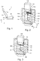
- Fig. 1:
- is a side view of a vehicle seat,
- Fig. 2:
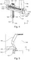
- is a perspective view of a backrest having a headrest which is arranged in a position for use and a headrest retraction member according to a first embodiment,
- Fig. 3:
- shows the arrangement from
Figure 2 , wherein the headrest is lowered into a non-use position, - Fig. 4:
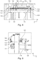
- is a perspective detailed view of the headrest retraction member of the first embodiment, wherein the headrest is located in the position for use and a locking member is in engagement with notches of two headrest rods,
- Fig. 5:
- is a perspective detailed view of a contact region between a sliding member and a locking member of the headrest retraction member in accordance with the first embodiment,
- Fig. 6:
- is a perspective cutout of the backrest from
Figure 2 , wherein the sliding member is slightly lowered, whereby the locking member and the notches are out of engagement, but the headrest is still in the position for use, - Fig. 7:
- is a perspective cutout of the backrest from
Figure 2 , wherein the sliding member is completely lowered and the headrest is located in the non-use position, - Fig. 8:
- is a cutout of a plan view of the backrest from
Figure 2 , wherein the headrest is located in the position for use, and the locking member is in engagement with the notches of the headrest rods, - Fig. 9:
- is another perspective detailed view of the contact region between the sliding member and the locking member of the headrest retraction member of the first embodiment,
- Fig. 10:
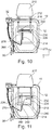
- is a plan view of a backrest having a headrest which is arranged in a position for use and a headrest retraction member according to a second embodiment,
- Fig. 11:
- shows the arrangement from
Figure 10 , wherein the headrest is lowered into a non-use position, - Fig. 12:
- is a perspective detailed view of the headrest retraction member of the second embodiment, wherein the headrest is located in the position for use and a locking member is in engagement with notches of two headrest rods,
- Fig. 13:
- is a cutout of a plan view of the backrest of
Figure 10 , wherein the headrest is located in the position for use, and the locking member is in engagement with the notches of the headrest rods, - Fig. 14:
- is a plan view of a backrest with a headrest arranged in a position for use and a headrest retraction member according to a third embodiment,
- Fig. 15:
- shows the arrangement from
Figure 14 , wherein the headrest is lowered into a non-use position, - Fig. 16:
- is a perspective view of the headrest retraction member according to the third embodiment, wherein the headrest is located in the position for use, and the locking member is in engagement with the notches of the headrest rods,
- Fig. 17
- is a perspective detailed view of a contact region between a rocker arm and a locking member of the headrest retraction member according to the third embodiment,
- Fig. 18:
- is a perspective view of the headrest retraction member of the third embodiment, wherein the headrest is located in the position for use, the rocker arm is slightly redirected and the locking member and the notches are out of engagement, and
- Fig. 19:
- is a view corresponding to
Figure 18 , wherein the rocker arm is completely redirected and the headrest is located in the non-use position. - The vehicle seat 1 illustrated schematically in the Figures and the embodiments of
headrest retraction members 100, 200, 300 according to the invention are described below using three spatial directions which extend perpendicularly relative to each other. A longitudinal direction x extends in a vehicle seat 1 which is installed in the vehicle in a substantially horizontal manner and preferably parallel with a vehicle longitudinal direction, which corresponds to the conventional travel direction of the vehicle. A transverse direction y which extends perpendicularly to the longitudinal direction x is also orientated horizontally in the vehicle and extends parallel with a vehicle transverse direction. A vertical direction z extends perpendicularly to the longitudinal direction x and perpendicularly to the transverse direction y. With a vehicle seat 1 which is installed in the vehicle, the vertical direction z extends parallel with the vertical axis of the vehicle. - The positional and directional indications used, such as, for example, front, rear, upper and lower refer to a viewing direction of an occupant sitting in the vehicle seat 1 in a normal seating position, wherein the vehicle seat 1 is installed in the vehicle, is in a position for use which is suitable for transporting passengers with an upright backrest and is orientated in conventional manner in the travel direction. However, the vehicle seat 1 according to the invention can also be installed in a different orientation, for example, transversely relative to the travel direction.
- The vehicle seat 1 has a
backrest 10, aseat member 20 and aheadrest backrest 10. Thebackrest 10 has a supportingbackrest structure 12 and anupholstery 14. Thebackrest 10 can be pivoted relative to theseat member 20 about a backrest pivot axis A which extends in the transverse direction y and which is defined by a fitting 30 and a rotary bearing. The fitting 30 can be unlocked by means of an operatinglever 32 which is operationally connected to the fitting 30 so that thebackrest 10 can be pivoted forwards out of the position for use about a backrest pivot axis A into the non-use position. During the transition of thebackrest 10 from the position for use into the non-use position, theheadrest headrest retraction member 100, 200, 300 according to the invention from a position for use into a non-use position. - The fitting 30 comprises a first fitting member and a second fitting member which can be rotated relative to the fitting 30 about the backrest pivot axis A when the fitting 30 is unlocked. The first fitting member is securely connected to the structure of the
seat member 20, that is to say, so as to be fixed to the seat member. The second seat member is securely connected to thebackrest structure 12 of thebackrest 10, that is to say, so as to be fixed to the backrest. The fitting 30 may be constructed as a catch fitting, as known, for example, fromDE 10 2009 041 492 A1 -
Figures 2 to 9 show as a first embodiment aheadrest retraction member 100. InFigures 2 and 3 , the arrangement of aheadrest 110 and theheadrest retraction member 100 on thebackrest 10 of the vehicle seat 1 can be seen. Theheadrest 110 has twoheadrest rods 112 which in the position for use of thebackrest 10 extend substantially parallel with the vertical direction z, in particular radially with respect to the backrest pivot axis A. The twoheadrest rods 112 have in this instance a round cross-section. The twoheadrest rods 112 carry an upholstered headrest body 111 for supporting a head of an occupant of the vehicle seat 1. The ends of theheadrest rods 112 facing away from the headrest body 111 are connected to each other by means of abridge 114. Thebridge 114 has an elongate form and is orientated parallel with the transverse direction y. Each of two end regions of thebridge 114 is securely connected to an end of aheadrest rod 112. - Two
sleeves 116 are securely connected to thebackrest structure 12 and serve to support the twoheadrest rods 112. Each of the twoheadrest rods 112 is displaceably guided in one of the twosleeves 116. During an adjustment of the height of theheadrest 110, in particular during a movement of theheadrest 110 from the position for use into the non-use position, there is produced a relative displacement of the headrest body 111, theheadrest rods 112 and thebridge 114 relative to thebackrest structure 12 and thesleeves 116 which are secured to thebackrest structure 12. - The two
headrest rods 112 each have anotch 118. Thenotches 118 cooperate with a lockingmember 120 of theheadrest retraction member 100. The lockingmember 120 is movably supported parallel with the transverse direction y relative to thebackrest structure 12. The lockingmember 120 can be moved into and out of engagement with thenotches 118 of theheadrest rod 112 in a manner described below in greater detail. - The structure and the operating method of the
headrest retraction member 100 can be seen inFigures 4 to 9 . Theheadrest retraction member 100 has the lockingmember 120, a guidingportion 130, a slidingmember 140 as an actuation component, a guidingprofile 150 and aBowden cable 160. - The guiding
portion 130 can be connected to thebackrest structure 12 and, in the mounted state of the vehicle seat 1, is securely connected to thebackrest structure 12, for example, screwed. The guidingportion 130 has an elongate extent parallel with the transverse direction y. The guidingportion 130 supports the lockingmember 120 movably parallel with the transverse direction y and relative to thebackrest structure 12. The guidingportion 130 has a substantially C-shaped cross-section with two members extending parallel. The members have, at the sides thereof facing each other, a plurality ofribs 132 which are arranged beside each other in the transverse direction y and which are orientated parallel with the vertical direction z. Arib 132 of a first member and arib 132 of the second member of the guidingportion 130 are opposite each other, are arranged with a small spacing with respect to each other and between them receive the lockingmember 120 in such a manner that the lockingmember 120 is movably supported parallel with the transverse direction y in the guidingportion 130. - The locking
member 120 has an elongate and substantially planar base member, from which in the end regions an L-shapedhook 124 protrudes downwards in each case. An end of the lockingmember 120 can be moved by means of a displacement of the lockingmember 120 into and out of engagement with thenotch 118 of one of theheadrest rods 112. The other of the twoheadrest rods 112 extends through an opening in the base member of the lockingmember 120 in such a manner that an edge of the opening can be brought into and out of engagement with thenotch 118 of thisheadrest rod 112. The lockingmember 120 is pretensioned by means of asecond compression spring 172 in the direction of thenotches 118. The lockingmember 120 can fall into thenotches 118, and thereby lock the relative position of theheadrest rods 112 relative to thebackrest structure 12, only if theheadrest 110 is located on the position for use. In a locking position of the lockingmember 120, the twohooks 124 engage below thebridge 114 and thereby additionally secure the position of theheadrest 110. The lockingmember 120 has an additional opening whose edge has acontact region 122 and in which the slidingmember 140 can engage. - The sliding
member 140 is displaceably guided in the guidingprofile 150 parallel with theheadrest rods 112. The guidingprofile 150 is secured to the guidingportion 130 and/or thebackrest structure 12. The slidingmember 140 is arranged above thebridge 114 and is supported via afirst compression spring 171 on thebridge 114 in such a manner that, in a non-actuated state of theheadrest retraction member 100, the slidingmember 140 and thebridge 114 are slightly spaced apart from each other. - As can be seen in detail in
Figure 5 , the slidingmember 140 has afirst wedge face 142 and asecond wedge face 144. In the locked position for use of theheadrest 110, thefirst wedge face 142 is in contact with thecontact region 122. Thefirst wedge face 142 is arranged in such a manner that a movement of the slidingmember 140 in a downward direction leads to a displacement of the lockingmember 120 in the transverse direction y so that the lockingmember 120 and thenotches 118 move out of engagement. - The
Bowden cable 160 has acable pull 162 and asheath 164. TheBowden cable 160 connects the slidingmember 140 to a component of the fitting 30, which component can be moved relative to thebackrest 10, for example, the first fitting member which is connected to the structure of theseat member 20. In a modification of the embodiment, theBowden cable 160 connects the slidingmember 140 to the operatinglever 32. Thesheath 164 is supported, on the one hand, on the guidingprofile 150. An end of thecable pull 162 is connected to the slidingmember 140. To this end, the end of thecable pull 162 is preferably provided with a fitting which is suspended in a slot of the slidingmember 140. The other end is connected to the component of the fitting 30, which component can be moved relative to thebackrest 10. - If the
backrest 10 is pivoted out of the position for use into the non-use position, the cable pull 162 first pulls the slidingmember 140 with pretensioning of thefirst compression spring 171 downwards until the slidingmember 140 is in abutment with thebridge 114. In this instance, the lockingmember 120 is displaced by thefirst wedge face 142 so that the lockingmember 120 and thenotches 118 move out of engagement and theheadrest 110 is thereby no longer locked relative to thebackrest structure 12. Subsequently, the slidingmember 140 is moved further downwards by means of thecable pull 162 and is released from the lockingmember 120. As a result of the contact between the slidingmember 140 and thebridge 114, thebridge 114 and consequently theheadrest 110 is also moved until the slidingmember 140 moves into an end stop, preferably on the guiding profile 150.The position of the slidingmember 140 then corresponds to the non-use position of theheadrest 110. - After the
backrest 10 has been pivoted back into the position for use thereof, theheadrest 110 can be moved manually again into the position for use thereof. Thebridge 114 in this instance also carries the slidingmember 140 upwards. Thesecond wedge face 144 of the slidingmember 140 in this instance moves initially into contact with thecontact region 122 of the lockingmember 120 and displaces it slightly in the opening direction. Subsequently, thesecond wedge face 144 passes thecontact region 122 of the lockingmember 120 until thecontact region 122 again moves into abutment with thefirst wedge face 142 and thefirst compression spring 171 relaxes. In this instance, thesecond compression spring 172 presses the lockingmember 120 again in the direction of thenotches 118 so that the lockingmember 120 again moves into engagement with thenotches 118 as soon as the position for use of theheadrest 110 is reached. -
Figures 10 to 13 show as a second embodiment a headrest retraction member 200.Figures 10 and 11 show the arrangement of aheadrest 210 and the headrest retraction member 200 on thebackrest 10 of the vehicle seat 1. Theheadrest 210 has twoheadrest rods 212 which extend in the position for use of thebackrest 10 substantially parallel with the vertical direction z, in particular radially relative to the backrest pivot axis A. The twoheadrest rods 212 in this instance have a round cross-section. The twoheadrest rods 212 carry an upholstered headrest body 211 for supporting a head of an occupant of the vehicle seat 1. The ends of theheadrest rods 212 facing away from the headrest body 211 are connected to each other by means of abridge 214. Thebridge 214 has an elongate form and is orientated parallel with the transverse direction y. Each of two end regions of thebridge 214 is securely connected to an end of aheadrest rod 212. Thebridge 214 is pretensioned by means of an energy accumulator which is constructed in this instance as atension spring 273 in the direction of the non-use position of theheadrest 210. An end of thetension spring 273 is connected to thebridge 214. The other end of thetension spring 273 is connected to thebackrest structure 12. - In
Figure 10 , theheadrest 210 is in the position for use and thetension spring 273 is tensioned. InFigure 11 , theheadrest 210 is in the non-use position and thetension spring 273 is substantially relaxed and concealed inFigure 11 by thebridge 214 and therefore cannot be seen. - Two
sleeves 216 are securely connected to thebackrest structure 12 and serve to support the twoheadrest rods 212. Each of the twoheadrest rods 212 is displaceably guided in one of the twosleeves 216. During an adjustment of the height of theheadrest 210, in particular during a transfer of theheadrest 210 from the position for use into the non-use position, there is produced a relative displacement of the headrest body 211, theheadrest rods 212 and thebridge 214 relative to thebackrest structure 12 and thesleeves 216 which are secured to thebackrest structure 12. - Both
headrest rods 212 each have anotch 218. Thenotches 218 cooperate with a lockingmember 220 of the headrest retraction member 200. The lockingmember 220 is movably supported parallel with the transverse direction y relative to thebackrest structure 12. The lockingmember 220 can be moved into and out of engagement with thenotches 218 of theheadrest rod 212 in a manner which is described in greater detail below. - The structure and operating method of the headrest retraction member 200 correspond, unless otherwise described below, to the first embodiment and can be seen in
Figures 12 and 13 . The headrest retraction member 200 has the lockingmember 220, a guidingportion 230, a slidingmember 240 as an actuation component, a guidingprofile 250, aBowden cable 260 and thetension spring 273. - The guiding
portion 230 can be connected to thebackrest structure 12 and in the mounted state of the vehicle seat 1 is securely connected to thebackrest structure 12, for example, screwed. The guidingportion 230 has an elongate extent parallel with the transverse direction y. The guidingportion 230 supports the lockingmember 220 in a movable manner parallel with the transverse direction y and relative to thebackrest structure 12. The guidingportion 230 has a substantially C-shaped cross-section with two parallel members. The members have at the sides thereof which face each other a plurality ofribs 232 which are arranged beside each other in the transverse direction y and which are each orientated parallel with the vertical direction z. Arib 232 of a first member and arib 232 of the second member of the guidingportion 230 face each other, are arranged with small spacing with respect to each other and receive between them the lockingmember 220 in such a manner that the lockingmember 220 is movably supported parallel with the transverse direction y in the guidingportion 230. - The locking
member 220 has an elongate and substantially planar base member from which in the end regions an L-shapedhook 224 protrudes downwards in each case. An end of the lockingmember 220 can be moved into and out of engagement with thenotch 218 of one of theheadrest rods 212 by means of a displacement of the lockingmember 220. The other of the twoheadrest rods 212 extends through an opening in the base member of the lockingmember 220 in such a manner that an edge of the opening can be moved into and out of engagement with thenotch 218 of thisheadrest rod 212. The lockingmember 220 is pretensioned by means of asecond compression spring 272 in the direction of thenotches 218. The lockingmember 220 can fall into thenotches 218, and thereby lock the relative position of theheadrest rods 212 relative to thebackrest structure 12, only when theheadrest 210 is in the position for use. In the locking position of the lockingmember 220, the twohooks 224 engage below thebridge 214 and thereby additionally secure the position of theheadrest 210. The lockingmember 220 has an additional opening whose edge has acontact region 222 and in which the slidingmember 240 can engage. - The sliding
member 240 is displaceably guided in the guidingprofile 250 parallel with theheadrest rods 212. The guidingprofile 250 is secured to the guidingportion 230 and/or thebackrest structure 12. The slidingmember 240 is arranged above thebridge 214 and is supported via afirst compression spring 271 on thebridge 214 in such a manner that, in an inactivated state of the headrest retraction member 200, the slidingmember 240 and thebridge 214 are slightly spaced apart from each other. - The sliding
member 240 has afirst wedge face 242 and asecond wedge face 244. In the locked position for use of theheadrest 210, thefirst wedge face 242 is in contact with thecontact region 222. Thefirst wedge face 242 is arranged in such a manner that a movement of the slidingmember 240 in a downward direction leads to a displacement of the lockingmember 220 in the transverse direction y so that the lockingmember 220 and thenotches 218 move out of engagement. - The
Bowden cable 260 has acable pull 262 and asheath 264. TheBowden cable 260 connects the slidingmember 240 to a component of the fitting 30, which component can be moved relative to thebackrest 10, for example, the first fitting member which is connected to the structure of theseat member 20. In a modification of the embodiment, theBowden cable 260 connects the slidingmember 240 to the operatinglever 32. Thesheath 264 is supported, on the one hand, on the guidingprofile 250. An end of thecable pull 262 is connected to the slidingmember 240. To this end, the end of thecable pull 262 is preferably provided with a fitting which is suspended in a slot of the slidingmember 240. The other end is connected to the component of the fitting 30 movable relative to thebackrest 10. - If the
backrest 10 is pivoted out of the position for use into the non-use position, thecable pull 262 pulls the slidingmember 240 with pretensioning of thefirst compression spring 271 downwards until the slidingmember 240 is in abutment with thebridge 214. In this instance, the lockingmember 220 is displaced by thefirst wedge face 242 so that the lockingmember 220 and thenotches 218 move out of engagement and theheadrest 210 is thereby no longer locked relative to thebackrest structure 12. Subsequently, thebridge 214 is pulled downwards by thetension spring 273. The slidingmember 240 is thereby released from the lockingmember 220. - The
bridge 214 and consequently theheadrest 210 are moved downwards by the relaxingtension spring 273 until the slidingmember 240 moves into an end stop, preferably on the guidingprofile 250. The position of the slidingmember 240 then corresponds to the non-use position of theheadrest 210. - After the
backrest 10 has been pivoted back into the position for use thereof, theheadrest 210 can again be manually moved into the position for use thereof with tensioning of thetension spring 273. In this instance, thebridge 214 also carries the slidingmember 240 upwards. In this case, thesecond wedge face 244 of the slidingmember 240 initially moves into contact with thecontact region 222 of the lockingmember 220 and displaces it slightly in the opening direction. Thesecond wedge face 244 subsequently passes thecontact region 222 of the lockingmember 220 until thecontact region 222 is again in abutment with thefirst wedge face 242 and thefirst compression spring 271 relaxes. In this instance, thesecond compression spring 272 presses the lockingmember 220 again in the direction of thenotches 218 so that the lockingmember 220 again moves into engagement with thenotches 218 as soon as the position for use of theheadrest 210 has been reached. -
Figures 14 to 19 show as a third embodiment a headrest retraction member 300.Figures 14 and 15 show the arrangement of aheadrest 310 and the headrest retraction member 300 on thebackrest 10 of the vehicle seat 1. Theheadrest 310 has twoheadrest rods 312, which extend in the position for use of thebackrest 10 substantially parallel with the vertical direction z, in particular radially with respect to the backrest pivot axis A. The twoheadrest rods 312 in this instance have a round cross-section. The twoheadrest rods 312 carry an upholstered headrest body 311 for supporting a head of an occupant of the vehicle seat 1. The ends of theheadrest rods 312 facing away from the headrest body 311 are connected to each other by means of abridge 314. Thebridge 314 has an elongate form and is orientated parallel with the transverse direction y. Each of two end regions of thebridge 314 is securely connected to an end of aheadrest rod 312. - Two
sleeves 316 are securely connected to thebackrest structure 12 and serve to support the twoheadrest rods 312. Each of the twoheadrest rods 312 is displaceably guided in one of the twosleeves 316. During an adjustment of the height of theheadrest 310, in particular during a transfer of theheadrest 310 from the position for use into the non-use position, there is produced a relative displacement of the headrest body 311, theheadrest rods 312 and thebridge 314 relative to thebackrest structure 12 and thesleeves 316 which are secured to thebackrest structure 12. - Both
headrest rods 312 have anotch 318. Thenotches 318 cooperate with a lockingmember 320 of the headrest retraction member 300. The lockingmember 320 is movably supported parallel with the transverse direction y relative to thebackrest structure 12. The lockingmember 320 can be moved into and out of engagement with thenotches 318 of theheadrest rod 312 in a manner which is described in greater detail below. - The headrest retraction member 300 has the locking
member 320, a guidingmember 330, arocker arm 380 as an actuation component, aredirection segment 390 and aBowden cable 360. - The guiding
portion 330 can be connected to thebackrest structure 12 and, in the assembled state of the vehicle seat 1, is securely connected to thebackrest structure 12, for example, screwed. The guidingportion 330 has an elongate extent parallel with the transverse direction y. The guidingportion 330 supports the lockingmember 320 in a movable manner parallel with the transverse direction y and relative to thebackrest structure 12. The guidingportion 330 has a substantially C-shaped cross-section having two members which extend in a parallel manner. The members have at the sides thereof facing each other a plurality ofribs 332 which are arranged beside each other in the transverse direction y and which are each orientated parallel with the vertical direction z. Arib 332 of a first member and arib 332 of the second member of the guidingportion 330 face each other, are arranged with small spacing with respect to each other and between them receive the lockingmember 320 in such a manner that the lockingmember 320 is supported parallel with the transverse direction y so as to be able to be moved in the guidingportion 330. - The locking
member 320 has an elongate and substantially planar base member from which an L-shapedhook 324 protrudes downwards in the end regions. An end of the lockingmember 320 can be moved into and out of engagement with thenotch 318 of one of theheadrest rods 312 by means of a displacement of the lockingmember 320. The other of the twoheadrest rods 312 extends through an opening in the base member of the lockingmember 320 in such a manner that an edge of the opening can be moved into and out of engagement with thenotch 318 of thisheadrest rod 312. The lockingmember 320 is pretensioned in the direction of thenotches 318 by means of a compression spring which is not illustrated in the Figures. The lockingmember 320 can fall into thenotches 318, and thereby lock the relative position of theheadrest rods 312 relative to thebackrest structure 12, only when theheadrest 310 is located in the position for use. In the locking position of the lockingmember 320, the twohooks 324 engage below thebridge 314 and thereby additionally secure the position of theheadrest 310. The lockingmember 320 has an additional opening whose edge has acontact region 322 and in which afinger 382 of therocker arm 380 can engage, whichfinger 382 has afirst wedge face 342 and asecond wedge face 344. - The
rocker arm 380 has an elongate base member. Thefinger 382 is arranged slightly off-centre between two ends of therocker arm 380. Thefinger 382 protrudes perpendicularly upwards from the base member of therocker arm 380. Thefinger 382 is in this instance constructed integrally with the base member of therocker arm 380. When theheadrest 310 is in the position for use, therocker arm 380 extends substantially parallel with thebridge 314 and consequently substantially parallel with the transverse direction y. Thefinger 382 is then substantially completely introduced in the corresponding opening in the lockingmember 320. Thefirst wedge face 342 is in abutment with thecontact region 322 of the lockingmember 320 when theheadrest 310 is in the position for use. - An end of the
rocker arm 380 has abearing aperture 384 for rotatable support of therocker arm 380. The bearingaperture 384 is supported on apin 388. Thepin 388 is secured to thebackrest structure 12, for example, screwed or welded. At an end of therocker arm 380 opposite the bearingaperture 384, there is formed acam 386 which can be positioned at the top on thebridge 314. A torsion spring which is not illustrated in the Figures pretensions therocker arm 380 in such a manner that thecam 386 is acted on in the direction of thebridge 314. However, in the position for use of theheadrest 310, as a result of the contact between thefirst wedge face 342 and the lockingmember 320, thecam 386 is still slightly spaced apart from the lockingmember 320, as can be seen inFigure 16 . This spacing is required so that therocker arm 380 can be rotated until the lockingmember 320 is pulled out of thenotches 318. - The
redirection segment 390 has the basic form of a circle sector. Theredirection segment 390 is securely connected to thebackrest structure 12 by means of ascrew 392. TheBowden cable 360 has acable pull 362 and asheath 364. TheBowden cable 360 connects therocker arm 380 to a component of the fitting 30, which component can be moved relative to thebackrest 10, for example, the first fitting member which is connected to the structure of theseat member 20. In a modification of the embodiment, theBowden cable 360 connects therocker arm 380 to the operatinglever 32. Thesheath 364 is supported at one side on theredirection segment 390. An end of thecable pull 362 is guided via theredirection segment 390 and connected to therocker arm 380. To this end, the end of thecable pull 362 is preferably provided with a fitting, which is suspended in a slot of therocker arm 380. The other end is connected to the component of the fitting 30, which component can be moved relative to thebackrest 10. - In the locked position for use of the
headrest 310, thefirst wedge face 342 is in contact with thecontact region 322. Thefirst wedge face 342 is arranged in such a manner that a pivot movement of therocker arm 380 and consequently thefinger 382 in a downward direction leads to a displacement of the lockingmember 320 in a transverse direction y so that the lockingmember 320 and thenotches 318 move out of engagement. Subsequently, thebridge 314 is pivoted downwards by thetorsion spring 273. Thefinger 382 is thereby released from the lockingmember 320. - The
bridge 314 and consequently theheadrest 310 are moved downwards by therocker arm 380 which is accordingly pretensioned by the torsion spring until the non-use position of theheadrest 310 is reached. - After the
backrest 10 has been pivoted back into the position for use thereof, theheadrest 310 can again be manually moved into the position for use thereof. Thebridge 314 in this instance also carries therocker arm 380 upwards with the torsion spring being tensioned. In this instance, thesecond wedge face 344 of thefinger 382 initially moves into contact with thecontact region 322 of the lockingmember 320 and displaces it slightly in an opening direction. Thesecond wedge face 344 subsequently passes thecontact region 322 of the lockingmember 320 until thecontact region 322 is again in abutment with thefirst wedge face 342 and the compression spring which is not illustrated in the Figures relaxes. In this instance, the compression spring presses the lockingmember 320 again in the direction of thenotches 318 so that the lockingmember 320 again moves into engagement with thenotches 318 as soon as the position for use of theheadrest 310 is reached. - The features which have been disclosed in the above description, the claims and the drawings may be significant both individually and in combination for the implementation of the invention in its various embodiments.
- Although the invention has been described in detail in the drawings and the above description, the illustrations are intended to be understood to be illustrative and exemplary and non-limiting. In particular, the selection of the proportions of the individual elements which are graphically illustrated is not intended to be interpreted to be necessary or limiting. Furthermore, the invention is in particular not limited to the embodiments explained. Further variants of the invention and their construction will result for the person skilled in the art from the above disclosure, the Figures and the claims.
- Terms used in the claims such as "comprise", "have", "contain", "include" and the like do not exclude other elements or steps. The use of the indefinite article does not exclude a plurality. An individual device may carry out the functions of a plurality of units or devices mentioned in the claims.
-
- 1
- Vehicle seat
- 10
- Backrest
- 12
- Backrest structure
- 14
- Upholstery
- 20
- Seat member
- 30
- Fitting
- 32
- Operating lever
- 100, 200, 300
- Headrest retraction member
- 110, 210, 310
- Headrest
- 111, 211, 311
- Headrest body
- 112, 212, 312
- Headrest rod
- 114,214,314
- Bridge
- 116,216,316
- Sleeve
- 118, 218, 318
- Notch
- 120, 220, 320
- Locking member
- 122, 222, 322
- Contact region
- 124, 224, 324
- Hook
- 130, 230, 330
- Guiding member
- 132, 232, 332
- Rib
- 140, 240
- Sliding member, actuation component
- 142, 242, 342
- First wedge face
- 144, 244, 344
- Second wedge face
- 150, 250
- Guiding profile
- 160, 260, 360
- Bowden cable
- 162, 262, 362
- Cable pull
- 164, 264, 364
- Sheath
- 171, 271
- Energy accumulator, first compression spring
- 172, 272
- Energy accumulator, second compression spring
- 273
- Energy accumulator, tension spring
- 380
- Rocker arm, actuation component
- 382
- Finger
- 384
- Bearing aperture
- 386
- Cam
- 388
- Pin
- 390
- Redirection segment
- 392
- Screw
- A
- Backrest pivot axis
- x
- Longitudinal direction
- y
- Transverse direction
- z
- Vertical direction
Claims (15)
- Headrest retraction member (100, 200, 300) for transferring a headrest (110, 210, 310) of a vehicle seat (1) from a position for use into a non-use position, the headrest retraction member (100, 200, 300) having a movably supported locking member (120, 220, 320), which can be moved into and out of engagement with at least one notch (118, 218, 318) of at least one headrest rod (112, 212, 312) of the headrest (110, 210, 310), and a movably supported actuation component (140, 240, 380) which has a wedge face (142, 242, 342), wherein, in the event of a movement of the actuation component (140, 240, 380), the wedge face (142, 242, 342) acts on the locking member (120, 220, 320) in such a manner that the locking member (120, 220, 320) and the at least one notch (118, 218, 318) move out of engagement,
characterised in that,
the actuation component (140, 240, 380) is coupled to a cable pull (162, 262, 362). - Headrest retraction member (100, 200, 300) according to claim 1, characterised in that a first end of the cable pull (162, 262, 362) is directly connected to the actuation component (140, 240, 380).
- Headrest retraction member (100, 200, 300) according to either of the preceding claims, characterised in that a second end of the cable pull (162, 262, 362) can be connected to a fitting (30) in order to pivot a backrest (10) of the vehicle seat (1) or to an operating lever (32), in particular in order to actuate a fitting (30).
- Headrest retraction member (100, 200, 300) according to any one of the preceding claims, characterised in that an actuation of the cable pull (162, 262, 362) moves the actuation component (140, 240, 380).
- Headrest retraction member (100, 200, 300) according to any one of the preceding claims having a bridge (114, 214, 314) for connecting to an end region of the at least one headrest rod (112, 212, 312), in particular for connecting the end regions of two headrest rods (112, 212, 312) of the headrest (110, 210, 310).
- Headrest retraction member (100, 200) according to any one of the preceding claims, characterised in that the actuation component is a sliding member (140, 240) which is displaceably guided in a guiding profile (150, 250).
- Headrest retraction member (100, 300) according to any one of the preceding claims, characterised in that the cable pull (162, 362) can be connected at least indirectly to the headrest (110, 310) in such a manner that, by means of an actuation of the cable pull (162, 362), in particular after carrying out a free travel, the cable pull (162, 362) pulls the headrest (110, 310) out of the position for use into the non-use position.
- Headrest retraction member (100) according to claims 5 to 7, characterised in that, when the sliding member (140) is displaced, a wedge face (142) of the sliding member (140) initially brings the locking member (120) and the at least one notch (118) out of engagement and subsequently the sliding member (140) also carries the bridge (114) in the direction of the non-use position of the headrest (110).
- Headrest retraction member (200) according to any one of claims 1 to 6, characterised in that an energy accumulator, in particular a tension spring (273), moves the headrest (210) from the position for use into the non-use position as soon as the locking member (220) and the at least one notch (218) are out of engagement.
- Headrest retraction member (300) according to any one of claims 1 to 5 or 7, characterised in that the actuation component is a rocker arm (380) which is in particular rotatably supported relative to a backrest structure (12) of the vehicle seat (1).
- Headrest retraction member (300) according to claim 10, characterised in that the rocker arm (380) is pretensioned by means of a spring, in particular a torsion spring, in such a manner that the rocker arm (380) moves the headrest (310) at least indirectly out of the position for use into the non-use position as soon as the locking member (320) and the at least one notch (318) are out of engagement.
- Vehicle seat (1), in particular motor vehicle seat, having a backrest (10), a seat member (20) and a headrest (110, 210, 310), characterised in that the headrest (110, 210, 310) can be transferred by means of a headrest retraction member (100, 200, 300) according to any one of the preceding claims from a position for use into a non-use position.
- Vehicle seat (1) according to claim 12, characterised in that the backrest (10) is pivotably supported about a backrest pivot axis (A) by means of at least one fitting (30), and a second end of the cable pull (162, 362) is connected to a component of the fitting (30), which component can be moved relative to the backrest (10).
- Vehicle seat (1) according to claim 12, characterised in that a second end of the cable pull (262) is connected to an operating lever (32), in particular for actuating a fitting (30).
- Vehicle seat (1) according to any one of claims 12 to 14, characterised in that the headrest (110, 210, 310) has two headrest rods (112, 212, 312) which are each movably guided in one of two sleeves (116, 216, 316), wherein the two sleeves (116, 216, 316) are securely connected to a backrest structure (12) of the vehicle seat (1).
Priority Applications (1)
| Application Number | Priority Date | Filing Date | Title |
|---|---|---|---|
| EP16157973.5A EP3213959B1 (en) | 2016-03-01 | 2016-03-01 | Headrest retraction member, and vehicle seat |
Applications Claiming Priority (1)
| Application Number | Priority Date | Filing Date | Title |
|---|---|---|---|
| EP16157973.5A EP3213959B1 (en) | 2016-03-01 | 2016-03-01 | Headrest retraction member, and vehicle seat |
Publications (2)
| Publication Number | Publication Date |
|---|---|
| EP3213959A1 true EP3213959A1 (en) | 2017-09-06 |
| EP3213959B1 EP3213959B1 (en) | 2019-10-02 |
Family
ID=55521486
Family Applications (1)
| Application Number | Title | Priority Date | Filing Date |
|---|---|---|---|
| EP16157973.5A Active EP3213959B1 (en) | 2016-03-01 | 2016-03-01 | Headrest retraction member, and vehicle seat |
Country Status (1)
| Country | Link |
|---|---|
| EP (1) | EP3213959B1 (en) |
Cited By (1)
| Publication number | Priority date | Publication date | Assignee | Title |
|---|---|---|---|---|
| CN112937395A (en) * | 2019-11-26 | 2021-06-11 | 通用汽车环球科技运作有限责任公司 | Actuated rear row center headrest |
Citations (6)
| Publication number | Priority date | Publication date | Assignee | Title |
|---|---|---|---|---|
| DE10005817A1 (en) | 2000-02-10 | 2001-08-23 | Itw Ateco Gmbh | Mechanical headrest retraction with memory function |
| DE10157516A1 (en) * | 2001-11-23 | 2003-06-05 | Bayerische Motoren Werke Ag | Seat with folding backrest has device by which headrest can be adjusted between extended and retracted positions by at least one cable |
| DE102006061638A1 (en) * | 2006-12-27 | 2008-07-03 | Lear Corp., Southfield | Vehicle e.g. boat, seat arrangement for resting occupant, has adjusting mechanism with link having projections connected with supports, such that supports can move from locked to unlocked position when releasing mechanism is operated |
| EP2123504A2 (en) * | 2008-05-23 | 2009-11-25 | Seat, S.A. | Release mechanism for headrests of vehicle collapsible seats |
| US20100264714A1 (en) * | 2007-12-11 | 2010-10-21 | Tame Omar D | Manual retracting head restraint |
| DE102009041492A1 (en) | 2009-09-10 | 2011-03-24 | Keiper Gmbh & Co. Kg | Fitting for a vehicle seat |
-
2016
- 2016-03-01 EP EP16157973.5A patent/EP3213959B1/en active Active
Patent Citations (6)
| Publication number | Priority date | Publication date | Assignee | Title |
|---|---|---|---|---|
| DE10005817A1 (en) | 2000-02-10 | 2001-08-23 | Itw Ateco Gmbh | Mechanical headrest retraction with memory function |
| DE10157516A1 (en) * | 2001-11-23 | 2003-06-05 | Bayerische Motoren Werke Ag | Seat with folding backrest has device by which headrest can be adjusted between extended and retracted positions by at least one cable |
| DE102006061638A1 (en) * | 2006-12-27 | 2008-07-03 | Lear Corp., Southfield | Vehicle e.g. boat, seat arrangement for resting occupant, has adjusting mechanism with link having projections connected with supports, such that supports can move from locked to unlocked position when releasing mechanism is operated |
| US20100264714A1 (en) * | 2007-12-11 | 2010-10-21 | Tame Omar D | Manual retracting head restraint |
| EP2123504A2 (en) * | 2008-05-23 | 2009-11-25 | Seat, S.A. | Release mechanism for headrests of vehicle collapsible seats |
| DE102009041492A1 (en) | 2009-09-10 | 2011-03-24 | Keiper Gmbh & Co. Kg | Fitting for a vehicle seat |
Cited By (2)
| Publication number | Priority date | Publication date | Assignee | Title |
|---|---|---|---|---|
| CN112937395A (en) * | 2019-11-26 | 2021-06-11 | 通用汽车环球科技运作有限责任公司 | Actuated rear row center headrest |
| CN112937395B (en) * | 2019-11-26 | 2023-03-24 | 通用汽车环球科技运作有限责任公司 | Actuated rear row center headrest |
Also Published As
| Publication number | Publication date |
|---|---|
| EP3213959B1 (en) | 2019-10-02 |
Similar Documents
| Publication | Publication Date | Title |
|---|---|---|
| KR100610431B1 (en) | Car Seat Slide | |
| US10406946B2 (en) | Vehicle seat | |
| US8864209B2 (en) | One touch stow in floor seat assembly with automatic lateral displacement | |
| US9290116B2 (en) | Actuator and hardware system for a vehicle seat | |
| US6695405B2 (en) | Seat device including a fold-down back | |
| US10406956B2 (en) | One touch stow in floor seat assembly with automatic lateral displacement | |
| KR101679184B1 (en) | Vehicle seat, particularly a motor vehicle seat | |
| JP6609179B2 (en) | Automotive seat | |
| US20010013718A1 (en) | Mechanical neck rest retraction device with a memory function | |
| US7484808B2 (en) | Vision improving system for a head restraint | |
| CZ2008738A3 (en) | Adjusting system for a vehicle seat | |
| US20200001742A1 (en) | Automotive vehicle seat | |
| EP4294670B1 (en) | Vehicle seat with a locking element | |
| US7044554B2 (en) | Vehicle seat having a head restraint independent from its backrest | |
| US20130292982A1 (en) | Longitudinal seat adjuster for a vehicle seat having easy entry functionality and folding functionality | |
| CN103764441B (en) | Can regulate highly and/or the headrest of gradient for seat | |
| JP2004526626A (en) | Motor seat with motor | |
| KR101518644B1 (en) | Apparatus for locking arm rest in vehicle | |
| EP3243695B1 (en) | Vehicle seat | |
| EP3213959B1 (en) | Headrest retraction member, and vehicle seat | |
| EP1810873A1 (en) | Folding seat for vehicles | |
| US11571992B2 (en) | Adjustable motor vehicle seat | |
| JPH0736516Y2 (en) | Car seat armrest structure | |
| GB2503957A (en) | Angle adjustment device for a back rest of a car seat | |
| JP2011042266A (en) | Seat reclining device for vehicle |
Legal Events
| Date | Code | Title | Description |
|---|---|---|---|
| PUAI | Public reference made under article 153(3) epc to a published international application that has entered the european phase |
Free format text: ORIGINAL CODE: 0009012 |
|
| STAA | Information on the status of an ep patent application or granted ep patent |
Free format text: STATUS: REQUEST FOR EXAMINATION WAS MADE |
|
| 17P | Request for examination filed |
Effective date: 20160301 |
|
| AK | Designated contracting states |
Kind code of ref document: A1 Designated state(s): AL AT BE BG CH CY CZ DE DK EE ES FI FR GB GR HR HU IE IS IT LI LT LU LV MC MK MT NL NO PL PT RO RS SE SI SK SM TR |
|
| AX | Request for extension of the european patent |
Extension state: BA ME |
|
| RAP1 | Party data changed (applicant data changed or rights of an application transferred) |
Owner name: ADIENT LUXEMBOURG HOLDING S.A R.L. |
|
| RAP1 | Party data changed (applicant data changed or rights of an application transferred) |
Owner name: ADIENT LUXEMBOURG HOLDING S.A R.L. |
|
| REG | Reference to a national code |
Ref country code: DE Ref legal event code: R079 Ref document number: 602016021499 Country of ref document: DE Free format text: PREVIOUS MAIN CLASS: B60N0002480000 Ipc: B60N0002200000 |
|
| RIC1 | Information provided on ipc code assigned before grant |
Ipc: B60N 2/005 20060101ALI20190513BHEP Ipc: B60N 2/835 20180101ALI20190513BHEP Ipc: B60N 2/20 20060101AFI20190513BHEP |
|
| GRAP | Despatch of communication of intention to grant a patent |
Free format text: ORIGINAL CODE: EPIDOSNIGR1 |
|
| STAA | Information on the status of an ep patent application or granted ep patent |
Free format text: STATUS: GRANT OF PATENT IS INTENDED |
|
| INTG | Intention to grant announced |
Effective date: 20190625 |
|
| GRAS | Grant fee paid |
Free format text: ORIGINAL CODE: EPIDOSNIGR3 |
|
| GRAA | (expected) grant |
Free format text: ORIGINAL CODE: 0009210 |
|
| STAA | Information on the status of an ep patent application or granted ep patent |
Free format text: STATUS: THE PATENT HAS BEEN GRANTED |
|
| AK | Designated contracting states |
Kind code of ref document: B1 Designated state(s): AL AT BE BG CH CY CZ DE DK EE ES FI FR GB GR HR HU IE IS IT LI LT LU LV MC MK MT NL NO PL PT RO RS SE SI SK SM TR |
|
| REG | Reference to a national code |
Ref country code: GB Ref legal event code: FG4D |
|
| REG | Reference to a national code |
Ref country code: CH Ref legal event code: EP Ref country code: AT Ref legal event code: REF Ref document number: 1185815 Country of ref document: AT Kind code of ref document: T Effective date: 20191015 |
|
| REG | Reference to a national code |
Ref country code: DE Ref legal event code: R096 Ref document number: 602016021499 Country of ref document: DE |
|
| REG | Reference to a national code |
Ref country code: IE Ref legal event code: FG4D |
|
| REG | Reference to a national code |
Ref country code: NL Ref legal event code: MP Effective date: 20191002 |
|
| REG | Reference to a national code |
Ref country code: LT Ref legal event code: MG4D |
|
| REG | Reference to a national code |
Ref country code: AT Ref legal event code: MK05 Ref document number: 1185815 Country of ref document: AT Kind code of ref document: T Effective date: 20191002 |
|
| PG25 | Lapsed in a contracting state [announced via postgrant information from national office to epo] |
Ref country code: AT Free format text: LAPSE BECAUSE OF FAILURE TO SUBMIT A TRANSLATION OF THE DESCRIPTION OR TO PAY THE FEE WITHIN THE PRESCRIBED TIME-LIMIT Effective date: 20191002 Ref country code: LV Free format text: LAPSE BECAUSE OF FAILURE TO SUBMIT A TRANSLATION OF THE DESCRIPTION OR TO PAY THE FEE WITHIN THE PRESCRIBED TIME-LIMIT Effective date: 20191002 Ref country code: SE Free format text: LAPSE BECAUSE OF FAILURE TO SUBMIT A TRANSLATION OF THE DESCRIPTION OR TO PAY THE FEE WITHIN THE PRESCRIBED TIME-LIMIT Effective date: 20191002 Ref country code: PT Free format text: LAPSE BECAUSE OF FAILURE TO SUBMIT A TRANSLATION OF THE DESCRIPTION OR TO PAY THE FEE WITHIN THE PRESCRIBED TIME-LIMIT Effective date: 20200203 Ref country code: FI Free format text: LAPSE BECAUSE OF FAILURE TO SUBMIT A TRANSLATION OF THE DESCRIPTION OR TO PAY THE FEE WITHIN THE PRESCRIBED TIME-LIMIT Effective date: 20191002 Ref country code: BG Free format text: LAPSE BECAUSE OF FAILURE TO SUBMIT A TRANSLATION OF THE DESCRIPTION OR TO PAY THE FEE WITHIN THE PRESCRIBED TIME-LIMIT Effective date: 20200102 Ref country code: GR Free format text: LAPSE BECAUSE OF FAILURE TO SUBMIT A TRANSLATION OF THE DESCRIPTION OR TO PAY THE FEE WITHIN THE PRESCRIBED TIME-LIMIT Effective date: 20200103 Ref country code: PL Free format text: LAPSE BECAUSE OF FAILURE TO SUBMIT A TRANSLATION OF THE DESCRIPTION OR TO PAY THE FEE WITHIN THE PRESCRIBED TIME-LIMIT Effective date: 20191002 Ref country code: NO Free format text: LAPSE BECAUSE OF FAILURE TO SUBMIT A TRANSLATION OF THE DESCRIPTION OR TO PAY THE FEE WITHIN THE PRESCRIBED TIME-LIMIT Effective date: 20200102 Ref country code: NL Free format text: LAPSE BECAUSE OF FAILURE TO SUBMIT A TRANSLATION OF THE DESCRIPTION OR TO PAY THE FEE WITHIN THE PRESCRIBED TIME-LIMIT Effective date: 20191002 Ref country code: LT Free format text: LAPSE BECAUSE OF FAILURE TO SUBMIT A TRANSLATION OF THE DESCRIPTION OR TO PAY THE FEE WITHIN THE PRESCRIBED TIME-LIMIT Effective date: 20191002 Ref country code: ES Free format text: LAPSE BECAUSE OF FAILURE TO SUBMIT A TRANSLATION OF THE DESCRIPTION OR TO PAY THE FEE WITHIN THE PRESCRIBED TIME-LIMIT Effective date: 20191002 |
|
| PG25 | Lapsed in a contracting state [announced via postgrant information from national office to epo] |
Ref country code: HR Free format text: LAPSE BECAUSE OF FAILURE TO SUBMIT A TRANSLATION OF THE DESCRIPTION OR TO PAY THE FEE WITHIN THE PRESCRIBED TIME-LIMIT Effective date: 20191002 Ref country code: CZ Free format text: LAPSE BECAUSE OF FAILURE TO SUBMIT A TRANSLATION OF THE DESCRIPTION OR TO PAY THE FEE WITHIN THE PRESCRIBED TIME-LIMIT Effective date: 20191002 Ref country code: IS Free format text: LAPSE BECAUSE OF FAILURE TO SUBMIT A TRANSLATION OF THE DESCRIPTION OR TO PAY THE FEE WITHIN THE PRESCRIBED TIME-LIMIT Effective date: 20200224 Ref country code: RS Free format text: LAPSE BECAUSE OF FAILURE TO SUBMIT A TRANSLATION OF THE DESCRIPTION OR TO PAY THE FEE WITHIN THE PRESCRIBED TIME-LIMIT Effective date: 20191002 |
|
| PG25 | Lapsed in a contracting state [announced via postgrant information from national office to epo] |
Ref country code: AL Free format text: LAPSE BECAUSE OF FAILURE TO SUBMIT A TRANSLATION OF THE DESCRIPTION OR TO PAY THE FEE WITHIN THE PRESCRIBED TIME-LIMIT Effective date: 20191002 |
|
| REG | Reference to a national code |
Ref country code: DE Ref legal event code: R097 Ref document number: 602016021499 Country of ref document: DE |
|
| PG2D | Information on lapse in contracting state deleted |
Ref country code: IS |
|
| PG25 | Lapsed in a contracting state [announced via postgrant information from national office to epo] |
Ref country code: EE Free format text: LAPSE BECAUSE OF FAILURE TO SUBMIT A TRANSLATION OF THE DESCRIPTION OR TO PAY THE FEE WITHIN THE PRESCRIBED TIME-LIMIT Effective date: 20191002 Ref country code: RO Free format text: LAPSE BECAUSE OF FAILURE TO SUBMIT A TRANSLATION OF THE DESCRIPTION OR TO PAY THE FEE WITHIN THE PRESCRIBED TIME-LIMIT Effective date: 20191002 Ref country code: DK Free format text: LAPSE BECAUSE OF FAILURE TO SUBMIT A TRANSLATION OF THE DESCRIPTION OR TO PAY THE FEE WITHIN THE PRESCRIBED TIME-LIMIT Effective date: 20191002 Ref country code: IS Free format text: LAPSE BECAUSE OF FAILURE TO SUBMIT A TRANSLATION OF THE DESCRIPTION OR TO PAY THE FEE WITHIN THE PRESCRIBED TIME-LIMIT Effective date: 20200202 |
|
| PLBE | No opposition filed within time limit |
Free format text: ORIGINAL CODE: 0009261 |
|
| STAA | Information on the status of an ep patent application or granted ep patent |
Free format text: STATUS: NO OPPOSITION FILED WITHIN TIME LIMIT |
|
| PG25 | Lapsed in a contracting state [announced via postgrant information from national office to epo] |
Ref country code: SM Free format text: LAPSE BECAUSE OF FAILURE TO SUBMIT A TRANSLATION OF THE DESCRIPTION OR TO PAY THE FEE WITHIN THE PRESCRIBED TIME-LIMIT Effective date: 20191002 Ref country code: IT Free format text: LAPSE BECAUSE OF FAILURE TO SUBMIT A TRANSLATION OF THE DESCRIPTION OR TO PAY THE FEE WITHIN THE PRESCRIBED TIME-LIMIT Effective date: 20191002 Ref country code: SK Free format text: LAPSE BECAUSE OF FAILURE TO SUBMIT A TRANSLATION OF THE DESCRIPTION OR TO PAY THE FEE WITHIN THE PRESCRIBED TIME-LIMIT Effective date: 20191002 |
|
| 26N | No opposition filed |
Effective date: 20200703 |
|
| PG25 | Lapsed in a contracting state [announced via postgrant information from national office to epo] |
Ref country code: MC Free format text: LAPSE BECAUSE OF FAILURE TO SUBMIT A TRANSLATION OF THE DESCRIPTION OR TO PAY THE FEE WITHIN THE PRESCRIBED TIME-LIMIT Effective date: 20191002 |
|
| REG | Reference to a national code |
Ref country code: CH Ref legal event code: PL |
|
| PG25 | Lapsed in a contracting state [announced via postgrant information from national office to epo] |
Ref country code: SI Free format text: LAPSE BECAUSE OF FAILURE TO SUBMIT A TRANSLATION OF THE DESCRIPTION OR TO PAY THE FEE WITHIN THE PRESCRIBED TIME-LIMIT Effective date: 20191002 |
|
| REG | Reference to a national code |
Ref country code: BE Ref legal event code: MM Effective date: 20200331 |
|
| PG25 | Lapsed in a contracting state [announced via postgrant information from national office to epo] |
Ref country code: LU Free format text: LAPSE BECAUSE OF NON-PAYMENT OF DUE FEES Effective date: 20200301 |
|
| PG25 | Lapsed in a contracting state [announced via postgrant information from national office to epo] |
Ref country code: IE Free format text: LAPSE BECAUSE OF NON-PAYMENT OF DUE FEES Effective date: 20200301 Ref country code: CH Free format text: LAPSE BECAUSE OF NON-PAYMENT OF DUE FEES Effective date: 20200331 Ref country code: LI Free format text: LAPSE BECAUSE OF NON-PAYMENT OF DUE FEES Effective date: 20200331 |
|
| PG25 | Lapsed in a contracting state [announced via postgrant information from national office to epo] |
Ref country code: BE Free format text: LAPSE BECAUSE OF NON-PAYMENT OF DUE FEES Effective date: 20200331 |
|
| GBPC | Gb: european patent ceased through non-payment of renewal fee |
Effective date: 20200301 |
|
| PG25 | Lapsed in a contracting state [announced via postgrant information from national office to epo] |
Ref country code: GB Free format text: LAPSE BECAUSE OF NON-PAYMENT OF DUE FEES Effective date: 20200301 |
|
| PGFP | Annual fee paid to national office [announced via postgrant information from national office to epo] |
Ref country code: DE Payment date: 20220329 Year of fee payment: 7 |
|
| PG25 | Lapsed in a contracting state [announced via postgrant information from national office to epo] |
Ref country code: TR Free format text: LAPSE BECAUSE OF FAILURE TO SUBMIT A TRANSLATION OF THE DESCRIPTION OR TO PAY THE FEE WITHIN THE PRESCRIBED TIME-LIMIT Effective date: 20191002 Ref country code: MT Free format text: LAPSE BECAUSE OF FAILURE TO SUBMIT A TRANSLATION OF THE DESCRIPTION OR TO PAY THE FEE WITHIN THE PRESCRIBED TIME-LIMIT Effective date: 20191002 Ref country code: CY Free format text: LAPSE BECAUSE OF FAILURE TO SUBMIT A TRANSLATION OF THE DESCRIPTION OR TO PAY THE FEE WITHIN THE PRESCRIBED TIME-LIMIT Effective date: 20191002 |
|
| PGFP | Annual fee paid to national office [announced via postgrant information from national office to epo] |
Ref country code: FR Payment date: 20220325 Year of fee payment: 7 |
|
| PG25 | Lapsed in a contracting state [announced via postgrant information from national office to epo] |
Ref country code: MK Free format text: LAPSE BECAUSE OF FAILURE TO SUBMIT A TRANSLATION OF THE DESCRIPTION OR TO PAY THE FEE WITHIN THE PRESCRIBED TIME-LIMIT Effective date: 20191002 |
|
| REG | Reference to a national code |
Ref country code: DE Ref legal event code: R081 Ref document number: 602016021499 Country of ref document: DE Owner name: ADIENT US LLC, PLYMOUTH, US Free format text: FORMER OWNER: ADIENT LUXEMBOURG HOLDING S.A R.L., LUXEMBOURG, LU |
|
| REG | Reference to a national code |
Ref country code: DE Ref legal event code: R119 Ref document number: 602016021499 Country of ref document: DE |
|
| PG25 | Lapsed in a contracting state [announced via postgrant information from national office to epo] |
Ref country code: FR Free format text: LAPSE BECAUSE OF NON-PAYMENT OF DUE FEES Effective date: 20230331 Ref country code: DE Free format text: LAPSE BECAUSE OF NON-PAYMENT OF DUE FEES Effective date: 20231003 |