EP3213717A1 - Einführkatheter und katheteranordnung - Google Patents
Einführkatheter und katheteranordnung Download PDFInfo
- Publication number
- EP3213717A1 EP3213717A1 EP17158339.6A EP17158339A EP3213717A1 EP 3213717 A1 EP3213717 A1 EP 3213717A1 EP 17158339 A EP17158339 A EP 17158339A EP 3213717 A1 EP3213717 A1 EP 3213717A1
- Authority
- EP
- European Patent Office
- Prior art keywords
- implant
- distal
- proximal
- catheter
- support member
- Prior art date
- Legal status (The legal status is an assumption and is not a legal conclusion. Google has not performed a legal analysis and makes no representation as to the accuracy of the status listed.)
- Granted
Links
Images

Classifications
-
- A—HUMAN NECESSITIES
- A61—MEDICAL OR VETERINARY SCIENCE; HYGIENE
- A61F—FILTERS IMPLANTABLE INTO BLOOD VESSELS; PROSTHESES; DEVICES PROVIDING PATENCY TO, OR PREVENTING COLLAPSING OF, TUBULAR STRUCTURES OF THE BODY, e.g. STENTS; ORTHOPAEDIC, NURSING OR CONTRACEPTIVE DEVICES; FOMENTATION; TREATMENT OR PROTECTION OF EYES OR EARS; BANDAGES, DRESSINGS OR ABSORBENT PADS; FIRST-AID KITS
- A61F2/00—Filters implantable into blood vessels; Prostheses, i.e. artificial substitutes or replacements for parts of the body; Appliances for connecting them with the body; Devices providing patency to, or preventing collapsing of, tubular structures of the body, e.g. stents
- A61F2/02—Prostheses implantable into the body
- A61F2/24—Heart valves ; Vascular valves, e.g. venous valves; Heart implants, e.g. passive devices for improving the function of the native valve or the heart muscle; Transmyocardial revascularisation [TMR] devices; Valves implantable in the body
- A61F2/2427—Devices for manipulating or deploying heart valves during implantation
-
- A—HUMAN NECESSITIES
- A61—MEDICAL OR VETERINARY SCIENCE; HYGIENE
- A61F—FILTERS IMPLANTABLE INTO BLOOD VESSELS; PROSTHESES; DEVICES PROVIDING PATENCY TO, OR PREVENTING COLLAPSING OF, TUBULAR STRUCTURES OF THE BODY, e.g. STENTS; ORTHOPAEDIC, NURSING OR CONTRACEPTIVE DEVICES; FOMENTATION; TREATMENT OR PROTECTION OF EYES OR EARS; BANDAGES, DRESSINGS OR ABSORBENT PADS; FIRST-AID KITS
- A61F2/00—Filters implantable into blood vessels; Prostheses, i.e. artificial substitutes or replacements for parts of the body; Appliances for connecting them with the body; Devices providing patency to, or preventing collapsing of, tubular structures of the body, e.g. stents
- A61F2/01—Filters implantable into blood vessels
- A61F2/0105—Open ended, i.e. legs gathered only at one side
-
- A—HUMAN NECESSITIES
- A61—MEDICAL OR VETERINARY SCIENCE; HYGIENE
- A61B—DIAGNOSIS; SURGERY; IDENTIFICATION
- A61B17/00—Surgical instruments, devices or methods
- A61B17/0057—Implements for plugging an opening in the wall of a hollow or tubular organ, e.g. for sealing a vessel puncture or closing a cardiac septal defect
-
- A—HUMAN NECESSITIES
- A61—MEDICAL OR VETERINARY SCIENCE; HYGIENE
- A61B—DIAGNOSIS; SURGERY; IDENTIFICATION
- A61B17/00—Surgical instruments, devices or methods
- A61B17/12—Surgical instruments, devices or methods for ligaturing or otherwise compressing tubular parts of the body, e.g. blood vessels or umbilical cord
- A61B17/12022—Occluding by internal devices, e.g. balloons or releasable wires
- A61B17/12099—Occluding by internal devices, e.g. balloons or releasable wires characterised by the location of the occluder
- A61B17/12122—Occluding by internal devices, e.g. balloons or releasable wires characterised by the location of the occluder within the heart
-
- A—HUMAN NECESSITIES
- A61—MEDICAL OR VETERINARY SCIENCE; HYGIENE
- A61B—DIAGNOSIS; SURGERY; IDENTIFICATION
- A61B17/00—Surgical instruments, devices or methods
- A61B17/34—Trocars; Puncturing needles
- A61B17/3468—Trocars; Puncturing needles for implanting or removing devices, e.g. prostheses, implants, seeds, wires
-
- A—HUMAN NECESSITIES
- A61—MEDICAL OR VETERINARY SCIENCE; HYGIENE
- A61F—FILTERS IMPLANTABLE INTO BLOOD VESSELS; PROSTHESES; DEVICES PROVIDING PATENCY TO, OR PREVENTING COLLAPSING OF, TUBULAR STRUCTURES OF THE BODY, e.g. STENTS; ORTHOPAEDIC, NURSING OR CONTRACEPTIVE DEVICES; FOMENTATION; TREATMENT OR PROTECTION OF EYES OR EARS; BANDAGES, DRESSINGS OR ABSORBENT PADS; FIRST-AID KITS
- A61F2/00—Filters implantable into blood vessels; Prostheses, i.e. artificial substitutes or replacements for parts of the body; Appliances for connecting them with the body; Devices providing patency to, or preventing collapsing of, tubular structures of the body, e.g. stents
- A61F2/02—Prostheses implantable into the body
- A61F2/24—Heart valves ; Vascular valves, e.g. venous valves; Heart implants, e.g. passive devices for improving the function of the native valve or the heart muscle; Transmyocardial revascularisation [TMR] devices; Valves implantable in the body
- A61F2/2427—Devices for manipulating or deploying heart valves during implantation
- A61F2/2436—Deployment by retracting a sheath
-
- A—HUMAN NECESSITIES
- A61—MEDICAL OR VETERINARY SCIENCE; HYGIENE
- A61F—FILTERS IMPLANTABLE INTO BLOOD VESSELS; PROSTHESES; DEVICES PROVIDING PATENCY TO, OR PREVENTING COLLAPSING OF, TUBULAR STRUCTURES OF THE BODY, e.g. STENTS; ORTHOPAEDIC, NURSING OR CONTRACEPTIVE DEVICES; FOMENTATION; TREATMENT OR PROTECTION OF EYES OR EARS; BANDAGES, DRESSINGS OR ABSORBENT PADS; FIRST-AID KITS
- A61F2/00—Filters implantable into blood vessels; Prostheses, i.e. artificial substitutes or replacements for parts of the body; Appliances for connecting them with the body; Devices providing patency to, or preventing collapsing of, tubular structures of the body, e.g. stents
- A61F2/95—Instruments specially adapted for placement or removal of stents or stent-grafts
- A61F2/962—Instruments specially adapted for placement or removal of stents or stent-grafts having an outer sleeve
- A61F2/966—Instruments specially adapted for placement or removal of stents or stent-grafts having an outer sleeve with relative longitudinal movement between outer sleeve and prosthesis, e.g. using a push rod
-
- A—HUMAN NECESSITIES
- A61—MEDICAL OR VETERINARY SCIENCE; HYGIENE
- A61B—DIAGNOSIS; SURGERY; IDENTIFICATION
- A61B17/00—Surgical instruments, devices or methods
- A61B17/0057—Implements for plugging an opening in the wall of a hollow or tubular organ, e.g. for sealing a vessel puncture or closing a cardiac septal defect
- A61B2017/00575—Implements for plugging an opening in the wall of a hollow or tubular organ, e.g. for sealing a vessel puncture or closing a cardiac septal defect for closure at remote site, e.g. closing atrial septum defects
- A61B2017/00623—Introducing or retrieving devices therefor
-
- A—HUMAN NECESSITIES
- A61—MEDICAL OR VETERINARY SCIENCE; HYGIENE
- A61B—DIAGNOSIS; SURGERY; IDENTIFICATION
- A61B17/00—Surgical instruments, devices or methods
- A61B17/12—Surgical instruments, devices or methods for ligaturing or otherwise compressing tubular parts of the body, e.g. blood vessels or umbilical cord
- A61B17/12022—Occluding by internal devices, e.g. balloons or releasable wires
- A61B2017/1205—Introduction devices
-
- A—HUMAN NECESSITIES
- A61—MEDICAL OR VETERINARY SCIENCE; HYGIENE
- A61B—DIAGNOSIS; SURGERY; IDENTIFICATION
- A61B17/00—Surgical instruments, devices or methods
- A61B17/12—Surgical instruments, devices or methods for ligaturing or otherwise compressing tubular parts of the body, e.g. blood vessels or umbilical cord
- A61B17/12022—Occluding by internal devices, e.g. balloons or releasable wires
- A61B2017/1205—Introduction devices
- A61B2017/12054—Details concerning the detachment of the occluding device from the introduction device
-
- A—HUMAN NECESSITIES
- A61—MEDICAL OR VETERINARY SCIENCE; HYGIENE
- A61B—DIAGNOSIS; SURGERY; IDENTIFICATION
- A61B17/00—Surgical instruments, devices or methods
- A61B17/34—Trocars; Puncturing needles
- A61B2017/347—Locking means, e.g. for locking instrument in cannula
-
- A—HUMAN NECESSITIES
- A61—MEDICAL OR VETERINARY SCIENCE; HYGIENE
- A61F—FILTERS IMPLANTABLE INTO BLOOD VESSELS; PROSTHESES; DEVICES PROVIDING PATENCY TO, OR PREVENTING COLLAPSING OF, TUBULAR STRUCTURES OF THE BODY, e.g. STENTS; ORTHOPAEDIC, NURSING OR CONTRACEPTIVE DEVICES; FOMENTATION; TREATMENT OR PROTECTION OF EYES OR EARS; BANDAGES, DRESSINGS OR ABSORBENT PADS; FIRST-AID KITS
- A61F2/00—Filters implantable into blood vessels; Prostheses, i.e. artificial substitutes or replacements for parts of the body; Appliances for connecting them with the body; Devices providing patency to, or preventing collapsing of, tubular structures of the body, e.g. stents
- A61F2/01—Filters implantable into blood vessels
- A61F2/011—Instruments for their placement or removal
-
- A—HUMAN NECESSITIES
- A61—MEDICAL OR VETERINARY SCIENCE; HYGIENE
- A61F—FILTERS IMPLANTABLE INTO BLOOD VESSELS; PROSTHESES; DEVICES PROVIDING PATENCY TO, OR PREVENTING COLLAPSING OF, TUBULAR STRUCTURES OF THE BODY, e.g. STENTS; ORTHOPAEDIC, NURSING OR CONTRACEPTIVE DEVICES; FOMENTATION; TREATMENT OR PROTECTION OF EYES OR EARS; BANDAGES, DRESSINGS OR ABSORBENT PADS; FIRST-AID KITS
- A61F2230/00—Geometry of prostheses classified in groups A61F2/00 - A61F2/26 or A61F2/82 or A61F9/00 or A61F11/00 or subgroups thereof
- A61F2230/0063—Three-dimensional shapes
- A61F2230/0067—Three-dimensional shapes conical
-
- A—HUMAN NECESSITIES
- A61—MEDICAL OR VETERINARY SCIENCE; HYGIENE
- A61F—FILTERS IMPLANTABLE INTO BLOOD VESSELS; PROSTHESES; DEVICES PROVIDING PATENCY TO, OR PREVENTING COLLAPSING OF, TUBULAR STRUCTURES OF THE BODY, e.g. STENTS; ORTHOPAEDIC, NURSING OR CONTRACEPTIVE DEVICES; FOMENTATION; TREATMENT OR PROTECTION OF EYES OR EARS; BANDAGES, DRESSINGS OR ABSORBENT PADS; FIRST-AID KITS
- A61F2250/00—Special features of prostheses classified in groups A61F2/00 - A61F2/26 or A61F2/82 or A61F9/00 or A61F11/00 or subgroups thereof
- A61F2250/0014—Special features of prostheses classified in groups A61F2/00 - A61F2/26 or A61F2/82 or A61F9/00 or A61F11/00 or subgroups thereof having different values of a given property or geometrical feature, e.g. mechanical property or material property, at different locations within the same prosthesis
- A61F2250/0018—Special features of prostheses classified in groups A61F2/00 - A61F2/26 or A61F2/82 or A61F9/00 or A61F11/00 or subgroups thereof having different values of a given property or geometrical feature, e.g. mechanical property or material property, at different locations within the same prosthesis differing in elasticity, stiffness or compressibility
-
- A—HUMAN NECESSITIES
- A61—MEDICAL OR VETERINARY SCIENCE; HYGIENE
- A61F—FILTERS IMPLANTABLE INTO BLOOD VESSELS; PROSTHESES; DEVICES PROVIDING PATENCY TO, OR PREVENTING COLLAPSING OF, TUBULAR STRUCTURES OF THE BODY, e.g. STENTS; ORTHOPAEDIC, NURSING OR CONTRACEPTIVE DEVICES; FOMENTATION; TREATMENT OR PROTECTION OF EYES OR EARS; BANDAGES, DRESSINGS OR ABSORBENT PADS; FIRST-AID KITS
- A61F2250/00—Special features of prostheses classified in groups A61F2/00 - A61F2/26 or A61F2/82 or A61F9/00 or A61F11/00 or subgroups thereof
- A61F2250/0014—Special features of prostheses classified in groups A61F2/00 - A61F2/26 or A61F2/82 or A61F9/00 or A61F11/00 or subgroups thereof having different values of a given property or geometrical feature, e.g. mechanical property or material property, at different locations within the same prosthesis
- A61F2250/0029—Special features of prostheses classified in groups A61F2/00 - A61F2/26 or A61F2/82 or A61F9/00 or A61F11/00 or subgroups thereof having different values of a given property or geometrical feature, e.g. mechanical property or material property, at different locations within the same prosthesis differing in bending or flexure capacity
-
- A—HUMAN NECESSITIES
- A61—MEDICAL OR VETERINARY SCIENCE; HYGIENE
- A61F—FILTERS IMPLANTABLE INTO BLOOD VESSELS; PROSTHESES; DEVICES PROVIDING PATENCY TO, OR PREVENTING COLLAPSING OF, TUBULAR STRUCTURES OF THE BODY, e.g. STENTS; ORTHOPAEDIC, NURSING OR CONTRACEPTIVE DEVICES; FOMENTATION; TREATMENT OR PROTECTION OF EYES OR EARS; BANDAGES, DRESSINGS OR ABSORBENT PADS; FIRST-AID KITS
- A61F2250/00—Special features of prostheses classified in groups A61F2/00 - A61F2/26 or A61F2/82 or A61F9/00 or A61F11/00 or subgroups thereof
- A61F2250/0014—Special features of prostheses classified in groups A61F2/00 - A61F2/26 or A61F2/82 or A61F9/00 or A61F11/00 or subgroups thereof having different values of a given property or geometrical feature, e.g. mechanical property or material property, at different locations within the same prosthesis
- A61F2250/0039—Special features of prostheses classified in groups A61F2/00 - A61F2/26 or A61F2/82 or A61F9/00 or A61F11/00 or subgroups thereof having different values of a given property or geometrical feature, e.g. mechanical property or material property, at different locations within the same prosthesis differing in diameter
-
- A—HUMAN NECESSITIES
- A61—MEDICAL OR VETERINARY SCIENCE; HYGIENE
- A61M—DEVICES FOR INTRODUCING MEDIA INTO, OR ONTO, THE BODY; DEVICES FOR TRANSDUCING BODY MEDIA OR FOR TAKING MEDIA FROM THE BODY; DEVICES FOR PRODUCING OR ENDING SLEEP OR STUPOR
- A61M25/00—Catheters; Hollow probes
- A61M2025/0098—Catheters; Hollow probes having a strain relief at the proximal end, e.g. sleeve
-
- A—HUMAN NECESSITIES
- A61—MEDICAL OR VETERINARY SCIENCE; HYGIENE
- A61M—DEVICES FOR INTRODUCING MEDIA INTO, OR ONTO, THE BODY; DEVICES FOR TRANSDUCING BODY MEDIA OR FOR TAKING MEDIA FROM THE BODY; DEVICES FOR PRODUCING OR ENDING SLEEP OR STUPOR
- A61M25/00—Catheters; Hollow probes
- A61M25/0009—Making of catheters or other medical or surgical tubes
- A61M25/0013—Weakening parts of a catheter tubing, e.g. by making cuts in the tube or reducing thickness of a layer at one point to adjust the flexibility
Definitions
- the invention relates to an introducer catheter for implanting a cardiovascular implant, in particular a prosthetic heart valve, having a first, inner catheter shaft disposed within at least a second, outer catheter shaft, wherein the implant is disposed on the first, inner catheter shaft in the distal region of the introducer catheter and wherein a portion near the distal end of the second outer catheter shaft is formed as an implant capsule for wrapping the implant during insertion. It further relates to a catheter assembly formed therewith.
- the invention relates to a delivery catheter for implanting a self-expanding implant.
- self-expanding implants are in particular stents, heart valve prostheses, venous valve prostheses, stent systems for closing the left atrial appendage, closing peristering foramen ovals, closing a persistent ductus arteriosus, closing a ventricular septal defect or closing an atrial septal defect (occluder or umbrella) or self-expanding filter or protector systems.
- the invention is particularly suitable for insertion catheters for heart valve prostheses, which have a self-expanding skeleton (heart valve stent) and a flap assembly attached thereto, for example of biological tissue.
- the invention will therefore be described mainly by the example of such a prosthetic heart valve, as it can be used for example as a replacement of a natural aortic valve.
- Minimally invasive surgical procedures have been gaining in importance for years and are indispensable for the treatment of stenosis, for example. Recently, they are also increasingly used in the implantation of artificial heart valves. Suitable insertion catheter are known in great constructive diversity and subject of constant further development. In recent years, special attention has been paid to the further development of catheters, which not only allow the insertion, but also the withdrawal or repositioning (if necessary) of cardiovascular implants.
- Such introducer catheters essentially consist of a first, inner catheter shaft, on the distal end of which the implant is arranged.
- the implant and the first, inner catheter shaft are surrounded by a second, outer catheter shaft.
- the distal portion of the second outer catheter shaft surrounding the implant is often referred to as an implant capsule, or occasionally a catheter sheath.
- the implant capsule may consist of the same material as the second outer catheter shaft or of another material, which is connected to the second outer catheter shaft.
- proximal a part of the insertion catheter lying closer to the practitioner is designated, “distal” correspondingly designates a part of the insertion catheter, which is located further away from the practitioner.
- the implants in particular the heart valve stent
- the implants are made of a shape memory material.
- the implants are held in their compressed form by the catheter sheath surrounding them during delivery to the site of implantation.
- the catheter sheath By displacing the catheter sheath, for example proximally, the retention force exerted by the catheter sheath on the implant disappears and the implant expands.
- the invention is therefore based on the object of providing an improved introducer catheter, in which, in particular, a kink formation in the area of the implant capsule is largely prevented and, as a result, a reliable and lightweight resorption should be enabled.
- the present invention includes the idea to provide a somewhat dynamic effective stiffening in the area of the implant capsule, which - unlike previously proposed solutions - not simply an overall stiffening of the capsule by increasing the wall thickness or by providing a particular represents thick inner catheter shaft.
- these previously proposed solutions have disadvantages with regard to the flexural softness of the catheter, in particular in the case of complex implant constructions, such as heart valve prostheses. The same applies to self-expanding implants that are to be released in smaller curved vessels.
- a bend-soft distal support element with a substantially frusto-conical section, which tapers in the proximal direction, and / or that at the proximal end of the implant capsule into the second, outer catheter shaft is fixedly positioned directly proximally from the implant at the first, inner catheter shaft positionally fixed a flexible soft proximal support member is inserted with a substantially frusto-conical portion which tapers in the proximal direction.
- the hereby provided in the implant capsule, each with respect to one of the relatively displaceable catheter elements movable Koni largely suppress the kink tendency at co-occurring bending moments and axial compressive forces, as observed in Resheathen. The hitherto observed buckling, collapse and thus failure of the distal outer catheter sheath or implant capsule can thereby be largely prevented.
- a frusto-conical section here means any substantially rotationally symmetrical frusto-conical shape which changes from a small cross section to a large cross section.
- These are on the one hand truncated cones in the strict mathematical sense as well as truncated cones, where the connection between the different cross sections of a straight line (as in a mathematical cone) deviates.
- these may also be truncated cones, in the section of which the outer sides are slightly concave or convex along the longitudinal axis.
- proximal directly from the implant is understood here an arrangement where the support element has no or only a very small distance from the implant.
- the support member would be directly proximal to such a retainer element.
- the proximal support element connects the second outer shaft with the actual implant capsule and thus forms a transition from the second outer shaft to the actual implant capsule.
- the proximal support member comprises a cylindrical distal portion whose diameter is matched to the inner diameter of the implant capsule and the outer diameter of the crimped implant, a cylindrical proximal portion whose outer diameter is matched to the inner diameter of the second outer catheter shaft, and a substantially truncated cone-shaped central portion which forms a continuous transition between the distal and proximal cylindrical portion. It may be specially designed as an injection-molded or rotary part, but optionally also be made by partial expansion of a pipe section. Also, the production by deep drawing or blow molding is conceivable. As the material for the support element, metals such as steel or Nitinol, or plastics are useful.
- the proximal support element in particular at least in the central portion, a plurality of incisions, which cause the bending softness of the support element. It is in particular designed so that the incisions each tangentially extend over a part, preferably the larger part of the circumference of the support element.
- the proximal support element is designed as a cone made of a slotted metal tube ("laser cut metal tube").
- the first proximal support element forms the connection between the second outer catheter shaft and the implant capsule or the proximal support element is inserted within the implant capsule at its proximal end and connected thereto.
- the proximal support member is configured to provide relative mobility between the second outer sheath and the first inner catheter shaft, that is, the proximal support member has a corresponding inner lumen that is at least the diameter of the first inner catheter shaft equivalent.
- the distal support element has a distal end, the outer diameter of which is adapted to the inner diameter of the implant capsule and the outer diameter of the crimped implant, and a proximal end whose inner diameter to the outer diameter of the first inner catheter shaft is adjusted.
- the distal support element is designed in particular as a solid or non-solid plastic part with an inner lumen whose diameter is adapted to the inner diameter of the first inner catheter shaft. From a current point of view, a production of the distal support element is preferred as a separate part from the inner catheter shaft, which is plugged onto the inner catheter shaft and welded or glued thereto.
- the distal support element can also be manufactured in one piece with the first, inner catheter shaft.
- the distal support member is preferably a spray or rotary member and may optionally have a plurality of cuts to increase the bending softness.
- the distal support element can be configured as described above for the proximal support element.
- the implant capsule is enlarged about the longitudinal extent of the distal, if provided, and / or the proximal support element, if provided, relative to the length related to the length of the crimped implant.
- an extension of the implant capsule can also be dispensed with.
- the dimensioning of the or each support element is selected so that the ratio between the length and the largest diameter of the support element between 2 and 7, preferably between 3 and 5 and particularly preferably between 3.5 and 4.5. Furthermore, in combination with these dimensioning rules or independently thereof, the ratio between the length of the distal and / or the proximal support element and the length of the implant capsule is preferably between 0.13 and 0.82, in particular between 0.28 and 0, 42nd
- the proximal and / or distal support element has a length of 10 mm to 50 mm, preferably between 20 mm and 25 mm.
- the largest diameter of the / the support element / support elements is then dependent on the wall thickness of the implant capsule used between 4.5 mm to 6.5 mm.
- an embodiment of the invention is preferred in which both a distal and a proximal support element are provided and together form a portion of the length of the implant capsule of at least 0.25 to 0.85, preferably 0.45 to 0.65 , support.
- this is more expensive than the provision of only one support element, but offers the greatest possible security against kinking and subsequent failure of the implant capsule or outer catheter sheath.
- the two support elements are preferably designed to fit into one another.
- the proximal support element is then preferably designed as a hollow body.
- the implant In the insertion state of the catheter, the implant is covered by the implant capsule and held in its compressed form. In the insertion state, therefore, the distal support element is preferably arranged on the inner shaft at least partially within the proximal support element, which forms a transition between the second outer catheter shaft and the implant capsule.
- a stop is preferably arranged within the proximal support element.
- angles of the conical portions of the proximal and distal support members may be configured differently. Both cones do not fit perfectly together.
- wedging of the support members may also be prevented by a corresponding surface design or surface structure (e.g., surface textures, grooves, nubs, etc.). All three embodiments to prevent wedging can be combined with each other.
- the insertion catheter has both a distal and a proximal support element.
- both support elements are preferably designed as turned parts made of stainless steel.
- the support elements are provided with incisions which extend tangentially over a part, preferably the largest part, of the circumference.
- the distal support element is preferably designed as an integral component with the implant connector.
- FIG. 1 shows schematically and not to scale, without regard to the wall thickness or other constructive details, the distal end of a delivery catheter 1 for insertion of a heart valve prosthesis 3, here shown in the partially retracted state in the distal end of the delivery catheter 1 (partial resheathing).
- the introducer catheter 1 comprises a first, inner catheter shaft 5 and a second, outer catheter shaft 7, and at the distal end of the latter, a diameter-expanded implant capsule 9 is provided.
- an implant connector 11 is attached, likewise in a manner known per se.
- the implant connector is connected to the first, inner catheter shaft and has eyelets or protrusions in which a corresponding counterpart of the implant engages in order to fix the implant axially on the first inner catheter shaft as long as the implant connector 11 of the implant capsule is covered.
- the reverse variant is also appropriate.
- the first inner catheter shaft 5 and the second outer catheter shaft 7 are displaceable relative to each other in the longitudinal direction of the insertion catheter 1, which both a release of the - typically made of a shape memory material - stent of the prosthetic heart valve 3 and the mentioned Resheathen thereof by manual control by the Operator from (not shown) proximal catheter end allows.
- a conical distal support member 13 is attached to the inner catheter shaft 5, and at the proximal end of the implant cartridge 9, a proximal support member 15 is attached to the outer catheter shaft 7. While the distal support member 13 is movable together with the inner catheter shaft 5, the proximal support member 15 is movable together with the outer catheter shaft 7.
- Each of the two support elements 13, 15 alone, and even better together, serves / serve to prevent kinking of the introducer catheter 1 in the region of its implant capsule and its subsequent rendering unusable in the return of the heart valve prosthesis 3 into the implant capsule 9.
- the distal support member 13 is connected to the implant connector 11.
- the connection can be carried out as a welded, glued, plugged or screwed connection. In principle, every connection comes into question. Equally expedient is an embodiment where the implant connector 11 and the distal support element 13 form an integral component.
- Fig. 2 shows an embodiment of the proximal support member 15, which here comprises a first cylindrical portion 15a, a second cylindrical portion 15b with a smaller diameter and the two cylindrical portions 15a, 15b interconnecting conical portion 15c. From the distal end of the cylindrical portion 15b to the distal end of the support member 15 this is formed by tangential over the much larger part of the circumference extending incisions 15d bendable.
- Distal support member 13 and / or proximal support member 15 may be designed as cut stainless steel cones. It is expedient to weld the cut stainless steel cones of the support element 13 and / or 15 with the cut stainless steel cores of the first inner and second outer catheter shaft. In this case, the cut stainless steel cores or stainless steel cones are advantageously wrapped inside and / or outside with plastic to ensure a frictionless sliding into each other or against the vessel wall. In addition, a seal is ensured by the plastic sheath.
- Fig. 3 shows an embodiment of the distal support member 13, which is designed in this embodiment as an integral stainless steel component with the implant connector 11.
- the implant connector 11 has receptacles 11a for a corresponding counterpart of the implant. Through these recordings 11a, the implant is fixed axially on the insertion catheter.
- the distal support member 13 also has recesses 13d along the circumference to increase flexural softness.
Landscapes
- Health & Medical Sciences (AREA)
- Cardiology (AREA)
- Life Sciences & Earth Sciences (AREA)
- Biomedical Technology (AREA)
- Engineering & Computer Science (AREA)
- General Health & Medical Sciences (AREA)
- Veterinary Medicine (AREA)
- Heart & Thoracic Surgery (AREA)
- Public Health (AREA)
- Animal Behavior & Ethology (AREA)
- Vascular Medicine (AREA)
- Oral & Maxillofacial Surgery (AREA)
- Transplantation (AREA)
- Surgery (AREA)
- Nuclear Medicine, Radiotherapy & Molecular Imaging (AREA)
- Medical Informatics (AREA)
- Molecular Biology (AREA)
- Reproductive Health (AREA)
- Pathology (AREA)
- Prostheses (AREA)
Abstract
Description
- Die Erfindung betrifft einen Einführkatheter zum Implantieren eines kardiovaskulären Implantats, insbesondere einer Herzklappenprothese, mit einem ersten, inneren Katheterschaft, welcher innerhalb von mindestens einem zweiten, äußeren Katheterschaft angeordnet ist, wobei das Implantat im distalen Bereich des Einführkatheters auf dem ersten, inneren Katheterschaft angeordnet ist und wobei ein Abschnitt nahe dem distalen Ende des zweiten, äußeren Katheterschafts als Implantatkapsel zur Umhüllung des Implantats während des Einführens ausgebildet ist. Sie betrifft des Weiteren eine mit diesem gebildete Katheteranordnung.
- Die Erfindung betrifft einen Einführkatheter zum Implantieren eines selbstexpandierenden Implantates. Derartige selbstexpandierende Implantate sind insbesondere Stents, Herzklappenprothesen, Venenklappenprothesen, Stentsysteme zum Verschließen des linken Herzohres, zum Verschließen peristierender Foramen Ovale, zum Verschluss eines persistierenden Ductus arteriosus, zum Verschluss eines Ventrikelseptumdefektes oder zum Verschluß eines Vorhofseptumdefektes (Okkluder oder Schirmchen) oder selbstexpandierende Filter- oder Protektorsysteme. Die Erfindung eignet sich insbesondere für Einführkatheter für Herzklappenprothesen, die ein selbstexpandierendes Grundgerüst (Herzklappenstent) und eine daran befestigte Klappenanordnung, beispielsweise aus biologischem Gewebe, aufweisen. Die Erfindung wird daher hauptsächlich am Beispiel einer derartigen Herzklappenprothese beschrieben, wie sie beispielsweise als Ersatz einer natürlichen Aortenklappe verwendet werden kann.
- Minimal invasive chirurgische Eingriffe gewinnen seit Jahren ständig an Bedeutung und sind beispielsweise zur Behandlung von Stenosen unverzichtbar. In letzter Zeit werden sie auch verstärkt bei der Implantation künstlicher Herzklappen eingesetzt. Geeignete Einführkatheter sind in großer konstruktiver Vielfalt bekannt und Gegenstand ständiger Weiterentwicklung. In den letzten Jahren wurde hier bei der Weiterentwicklung zu Kathetern besonderes Augenmerk geschenkt, die nicht nur das Setzen, sondern auch das Zurückziehen bzw. eine Repositionierung (wenn nötig) von kardiovaskulären Implantaten ermöglichen.
- Derartige Einführkatheter bestehen im Wesentlichen aus einem ersten, inneren Katheterschaft, auf dessen distalem Ende das Implantat angeordnet ist. Das Implantat und der erste, innere Katheterschaft sind von einem zweiten, äußeren Katheterschaft umgeben. Der distale Bereich des zweiten äußeren Katheterschafts, der das Implantat umgibt, wird häufig als Implantatkapsel, oder gelegentlich als Katheterhülle bezeichnet. Die Implantatkapsel kann dabei aus dem gleichen Material wie der zweite äußere Katheterschaft oder aus einem anderen Material bestehen, welches mit dem zweiten äußeren Katheterschaft verbunden wird. Hier wird unter der Positionsbezeichnung "proximal" ein näher zum Behandler liegender Teil des Einführkatheters bezeichnet, "distal" bezeichnet entsprechend einen Teil des Einführkatheters, der sich weiter entfernt vom Behandler befindet.
- Häufig sind die Implantate (insbesondere der Herzklappenstent) aus einem Formgedächtnismaterial ausgeführt. In diesen Fällen werden die Implantate während des Einführens an den Implantationsort durch die, sie umgebende, Katheterhülle in ihrer komprimierten Form gehalten. Durch Verschieben der Katheterhülle, beispielsweise nach proximal, verschwindet die Rückhaltekraft, die die Katheterhülle auf das Implantat ausübt, und das Implantat expandiert.
- Vor kurzem wurden Lösungen vorgeschlagen, die ein Zurückführen ("resheathing" oder "recapturing") eines bereits teilweise freigesetzten Implantats in den Einführkatheter, also speziell in die Implantatkapsel, ermöglichen sollen. Derartige Lösungen werden von den Operateuren stark begrüßt, weil sie Korrekturen während des Einführvorganges ermöglichen und somit helfen, den Implantationsvorgang mit dem bestmöglichen Ergebnis abzuschließen. Speziell in den Fällen, wo das Implantat durch ein Zurückziehen der Katheterhülle nach proximal freigesetzt wird, treten bei der Rückführung des Herzklappenstents in die Implantatkapsel bzw., präziser formuliert, beim Wiederaufstülpen des distalen Katheterendes über den Stent, relativ hohe Reaktionskräfte bzw. hohe lokale Spannungskonzentrationen auf. Diese führen zu komplexen Problemen wie beispielsweise in der Beschreibung des Standes der Technik in der
US 2011/0098804 beschrieben und mit dem Versuch einer (teilweisen) Lösung verknüpft ist. - Speziell kann es in Einzelfällen, wie die Erfinder bei entsprechenden praktischen Erprobungen bekannter Systeme festgestellt haben, zu einem funktionellen Versagen der Implantatkapsel beim Zurückführen über das Implantat kommen, und zwar speziell zur Bildung von Knickstellen an der Implantatkapsel, die das Resheathen erschweren oder praktisch oder ganz unmöglich machen.
- Der Erfindung liegt daher die Aufgabe der Bereitstellung eines verbesserten Einführkatheters zu Grunde, bei dem insbesondere eine Knickbildung im Bereich der Implantatkapsel weitgehend verhindert und hierdurch ein zuverlässiges und leichtes Resheathen ermöglicht werden soll.
- Diese Aufgabe wird durch einen Einführkatheter mit den Merkmalen des Anspruchs 1 gelöst. Zweckmäßige Fortbildungen des Erfindungsgedankens sind Gegenstand der abhängigen Ansprüche. Mit der Erfindung wird weiterhin eine verbesserte Einführkatheteranordnung bereitgestellt.
- Neben der oben erwähnten Erkenntnis der Erfinder schließt vorliegende Erfindung den Gedanken ein, im Bereich der Implantatkapsel eine gewissermaßen dynamisch wirksame Versteifung vorzusehen, die - anders als früher vorgeschlagene Lösungen - nicht einfach eine Gesamt-Versteifung der Kapsel durch Erhöhung der Wandstärke oder durch Vorsehen eines besonders dicken inneren Katheterschaftes darstellt. Diese früher vorgeschlagenen Lösungen haben nämlich nach den Feststellungen der Erfinder Nachteile in Bezug auf die Biegeweichheit des Katheters, insbesondere bei aufwändigen Implantatkonstruktionen, wie Herzklappenprothesen. Gleiches gilt für selbstexpandierende Implantate, die in kleineren gebogenen Gefäßen freigesetzt werden sollen.
- Erfindungsgemäß ist vorgesehen, dass direkt proximal vom Implantat am ersten, inneren Katheterschaft positionsfest ein biegeweiches distales Stützelement mit einem im wesentlichen kegelstumpfförmigen Abschnitt angebracht ist, der sich in proximaler Richtung verjüngt, und/oder dass am proximalen Ende der Implantatkapsel in den zweiten, äußeren Katheterschaft positionsfest ein biegeweiches proximales Stützelement mit einem im wesentlichen kegelstumpfförmigen Abschnitt eingefügt ist, der sich in proximaler Richtung verjüngt. Die hiermit im Bereich der Implantatkapsel vorgesehenen, jeweils in Bezug auf eines der relativ zueinander verschiebbaren Katheterelemente beweglichen Koni unterdrücken weitgehend die Knick-Neigung bei zusammen auftretenden Biegemomenten und axialen Druckkräften, wie sie beim Resheathen zu beobachten sind. Das bisher beobachtete Knicken, Kollabieren und somit Versagen der distalen äußeren Katheterhülle bzw. Implantatkapsel kann hierdurch weitgehend verhindert werden.
- Unter einem kegelstumpfförmigen Abschnitt wird hier jede im Wesentlichen rotationssymmetrische kegelstumpfartige Form verstanden, die sich von einem kleinen Querschnitt zu einem großen Querschnitt ändert. Dies sind zum Einen Kegelstümpfe im streng mathematischen Sinne als auch Kegelstümpfe, wo die Verbindung zwischen den unterschiedlichen Querschnitten von einer Geraden (wie bei einem mathematischen Kegel) abweicht. Dies können insbesondere auch Kegelstümpfe sein, bei deren Schnitt entlang der Längsachse die Außenseiten leicht konkav oder konvex sind.
- Unter direkt proximal vom Implantat wird hier eine Anordnung verstanden, wo das Stützelement keinen oder nur ein sehr geringen Abstand vom Implantat hat. Bei Einführkathetern, wo das Implantat an seinem proximalen Ende mit einem Halteelement mit dem ersten inneren Schaft verbunden oder anderweitig befestigt ist, würde sich das Stützelement direkt proximal neben einem derartigen Halteelement befinden.
- Das proximale Stützelement verbindet zusätzlich zu seiner Stützfunktion den zweiten äußeren Schaft mit der eigentlichen Implantatkapsel und bildet so einen Übergang vom zweiten äußeren Schaft auf die eigentliche Implantatkapsel.
- In einer Ausführung der Erfindung umfasst das proximale Stützelement einen zylindrischen distalen Abschnitt, dessen Durchmesser an den Innendurchmesser der Implantatkapsel und den Außendurchmesser des gecrimpten Implantats angepasst ist, einen zylindrischen proximalen Abschnitt, dessen Außendurchmesser an den Innendurchmesser des zweiten, äußeren Katheterschafts angepasst ist, und einen im wesentlichen kegelstumpf förmigen mittleren Abschnitt, der einen stetigen Übergang zwischen dem distalen und proximalen zylindrischen Abschnitt bildet. Es kann speziell als Spritzguss- oder Drehteil ausgebildet sein, gegebenenfalls aber auch durch partielles Aufweiten aus einem Rohrstück hergestellt sein. Ebenfalls ist die Herstellung mittels Tiefziehen oder Blasformung denkbar. Als Material für das Stützelement sind Metalle, wie Stahl oder Nitinol, oder Kunststoffe zweckmäßig.
- In einer weiteren Ausgestaltung weist das proximale Stützelement, insbesondere mindestens im mittleren Abschnitt, eine Vielzahl von Einschnitten auf, die die Biegeweichheit des Stützelementes bewirken. Es ist insbesondere so gestaltet, dass die Einschnitte sich jeweils über einen Teil, bevorzugt den größeren Teil des Umfangs des Stützelementes tangential erstrecken. In dieser Ausführungsform der Erfindung ist das proximale Stützelement als Konus aus einem geschlitzten Metallrohr ausgeführt ("laser cut metal tube").
- Bevorzugt bildet das erste proximale Stützelement die Verbindung zwischen dem zweiten äußeren Katheterschaft und der Implantatkapsel oder das proximale Stützelement wird innerhalb der Implantatkapsel an deren proximalen Ende eingesetzt und mit dieser verbunden. In jedem Fall ist das proximale Stützelement derart ausgestaltet, dass die relative Beweglichkeit zwischen dem zweiten äußeren Schaft bzw. Implantatkapsel und dem ersten inneren Katheterschaft gewährleistet ist, das heißt, dass proximale Stützelement weißt ein entsprechendes Innenlumen auf, welches mindestens dem Durchmesser des ersten inneren Katheterschafts entspricht.
- In einer weiteren Ausführung ist vorgesehen, dass das distale Stützelement ein distales Ende, dessen Außendurchmesser an den Innendurchmesser der Implantatkapsel und den Außendurchmesser des gecrimpten Implantats angepasst ist, und ein proximales Ende hat, dessen Innendurchmesser an den Außendurchmesser des ersten, inneren Katheterschafts angepasst ist. Des Weiteren ist das distale Stützelement insbesondere als massives oder nicht-massives Kunststoffteil mit einem Innenlumen ausgebildet, dessen Durchmesser an den Innendurchmesser des ersten, inneren Katheterschafts angepasst ist. Aus derzeitiger Sicht bevorzugt ist eine Fertigung des distalen Stützelementes als vom inneren Katheterschaft separates Teil, welches auf den inneren Katheterschaft aufgesteckt und mit diesem verschweißt oder verklebt wird. Grundsätzlich lässt sich das distale Stützelement aber auch einstückig mit dem ersten, inneren Katheterschaft fertigen. Auch das distale Stützelement ist bevorzugt ein Spritz- oder Drehteil und kann optional eine Vielzahl von Einschnitten zur Steigerung der Biegeweichheit aufweisen. Im Prinzip lässt sich das distale Stützelement wie vorangehend für das proximale Stützelement ausgestalten.
- In weiteren Ausführungen der Erfindung ist die Implantatkapsel um die Längserstreckung des distalen, falls vorgesehen, und/oder des proximalen Stützelementes, falls vorgesehen, gegenüber der auf die Länge des gecrimpten Implantats bezogene Länge vergrößert. Je nach konkreter Ausführung des Implantats einerseits und des distalen und/oder proximalen Stützelementes andererseits kann eine solche Verlängerung der Implantatkapsel aber auch verzichtbar sein.
- In weiteren Ausführungen der Erfindung ist die Dimensionierung des oder jedes Stützelementes so gewählt, dass das Verhältnis zwischen Länge und größtem Durchmesser des Stützelements zwischen 2 und 7, bevorzugt zwischen 3 und 5 und insbesondere bevorzugt zwischen 3,5 und 4,5 beträgt. Des Weiteren, in Kombination mit diesen Dimensionierungsvorschriften oder auch unabhängig hiervon, ist bevorzugt das Verhältnis zwischen der Länge des distalen und/oder des proximalen Stützelementes und der Länge der Implantatkapsel zwischen 0,13 und 0,82, insbesondere zwischen 0,28 und 0,42.
- In einer bevorzugten Ausgestaltung mit einer Implantatkapsel mit einem Außendurchmesser von 14 French (4,7 mm) bis 21 French (7 mm) und einer Länge von 60 mm bis 80 mm hat das proximale und/oder distale Stützelement eine Länge von 10 mm bis 50 mm, bevorzugt zwischen 20 mm und 25 mm. Der größte Durchmesser des/der Stützelementes/Stützelemente ist dann abhängig von der verwendeten Wandstärke der Implantatkapsel zwischen 4,5 mm bis 6,5 mm.
- Aus derzeitiger Sicht ist eine Ausführung der Erfindung bevorzugt, bei der sowohl ein distales als auch ein proximales Stützelement vorgesehen ist und beide zusammen einen Anteil der Länge der Implantatkapsel von mindestens 0,25 bis 0,85, bevorzugt von 0,45 bis 0,65, stützen. Diese ist zwar aufwändiger als das Vorsehen nur eines Stützelementes, bietet aber weitestgehende Sicherheit gegen ein Knicken und anschließendes Versagen der Implantatkapsel bzw. äußeren Katheterhülle.
- In Ausgestaltungen der Erfindung, wo sowohl ein distales und ein proximales Stützelement verwendet werden, werden die beiden Stützelement bevorzugt ineinander passend ausgeführt. Das proximale Stützelement wird dann bevorzugt als Hohlkörper ausgeführt. Im Einführzustand des Katheters wird das Implantat von der Implantatkapsel überdeckt und in seiner komprimierten Form gehalten. Im Einführzustand ist daher bevorzugt das distale Stützelement auf dem Innenschaft zumindest teilweise innerhalb des proximalen Stützelementes angeordnet, welches einen Übergang zwischen dem zweiten äußeren Katheterschaft und der Implantatkapsel bildet. Um ein Verkeilen des distalen Stützelementes im proximalen Stützelement zu verhindern, wird bevorzugt ein Anschlag innerhalb des proximalen Stützelementes angeordnet. Alternativ können die Winkel der konischen Abschnitte des proximalen und distalen Stützelementes unterschiedlich ausgestaltet werden. Beide Konen passen so nicht perfekt ineinander. Alternativ kann ein Verkeilen der Stützelemente auch durch eine entsprechende Oberflächengestaltung oder Oberflächenstruktur verhindert werden (z.B. Oberflächentexturen, Rillen, Noppen etc). Alle drei Ausgestaltungen zur Verhinderung des Verkeilens können beliebig miteinander kombiniert werden.
- In einer bevorzugten Ausgestaltung weist der Einführkatheter sowohl ein distales als auch ein proximales Stützelement auf. In dieser Ausgestaltung sind beide Stützelemente bevorzugt als Drehteile aus Edelstahl ausgeführt. Zur Erhöhung der Biegeweichheit sind die Stützelemente mit Einschnitten versehen, die sich über einen Teil, bevorzugt den größten Teil, des Umfangs tangential erstrecken. Das distale Stützelement ist bevorzugt als integrales Bauteil mit dem Implantat-Konnektor ausgeführt.
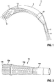
- Vorteile und Zweckmäßigkeiten der Erfindung ergeben sich im Übrigen aus der nachfolgenden Beschreibung eines Ausführungsbeispiels anhand der Figuren. Von diesen zeigen:
- Fig. 1
- eine schematische Längsschnittdarstellung des distalen Abschnitts eines Einführkatheters im Zustand des teilweisen Resheathing,
- Fig. 2
- eine perspektivische Darstellung einer Ausführungsform des proximalen Stützelements des Einführkatheters nach
Fig. 1 und - Fig. 3
- eine perspektivische Darstellung einer Ausführungsform des distalen Stützelementes nach
Fig. 1 -
Fig. 1 zeigt schematisch und unmaßstäblich, ohne Beachtung der Wandstärke oder sonstiger konstruktiver Einzelheiten, das distale Ende eines Einführkatheters 1 zur Einführung einer Herzklappenprothese 3, der hier im teilweise in das distale Ende des Einführkatheters 1 zurückgezogenen Zustand (partielles Resheathing) gezeigt ist. Der Einführkatheter 1 umfasst einen ersten, inneren Katheterschaft 5 und einen zweiten, äußeren Katheterschaft 7, und am distalen Ende des letzteren ist eine im Durchmesser aufgeweitete Implantatkapsel 9 vorgesehen. - Im distalen Endbereich des ersten, inneren Katheterschafts 5 ist, in ebenfalls an sich bekannter Weise, ein Implantat-Konnektor 11 angebracht. Der Implantat-Konnektor ist mit dem ersten, inneren Katheterschaft verbunden und weißt Ösen oder Ausformungen auf, in die ein entsprechendes Gegenstück des Implantats eingreift, um das Implantat axial auf dem ersten inneren Katheterschaft solange zu fixieren, wie der Implantat-Konnektor 11 von der Implantatkapsel überdeckt ist. Die umgekehrte Variante ist ebenso zweckmäßig. Der erste, innere Katheterschaft 5 und der zweite, äußere Katheterschaft 7 sind in Längsrichtung des Einführkatheters 1 relativ zueinander verschieblich, was sowohl ein Freisetzen des - typischerweise aus einem Formgedächtnismaterial gefertigten - Stents der Herzklappenprothese 3 als auch das erwähnte Resheathen desselben per manueller Steuerung durch den Operateur vom (nicht gezeigten) proximalen Katheterende aus ermöglicht. Direkt proximal am Implantat-Konnektor 11 ist ein konisches distales Stützelement 13 am inneren Katheterschaft 5 angebracht, und am proximalen Ende der Implantatkapsel 9 ist ein proximales Stützelement 15 am äußeren Katheterschaft 7 angebracht. Während das distale Stützelement 13 zusammen mit dem inneren Katheterschaft 5 beweglich ist, ist das proximale Stützelement 15 zusammen mit dem äußeren Katheterschaft 7 beweglich. Jedes der beiden Stützelemente 13, 15 für sich allein, und in noch verbesserter Weise beide zusammen, dient/dienen zur Verhinderung eines Knickens des Einführkatheters 1 im Bereich seiner Implantatkapsel und damit verbundenen Unbrauchbarwerdens desselben bei der Rückführung der Herzklappenprothese 3 in die Implantatkapsel 9.
- Bevorzugt ist das distale Stützelement 13 mit dem Implantat-Konnektor 11 verbunden. Die Verbindung kann als Schweiß-, Klebe-, Steck- oder Schraubverbindung ausgeführt werden. Prinzipiell kommt jede Verbindung in Frage. Ebenso zweckmäßig ist eine Ausführung, wo Implantat-Konnektor 11 und distales Stützelement 13 ein integrales Bauteil bilden.
-
Fig. 2 zeigt ein Ausführungsbeispiel des proximalen Stützelements 15, welches hier einen ersten zylindrischen Abschnitt 15a, einen zweiten zylindrischen Abschnitt 15b mit kleinerem Durchmesser und einen die beiden zylindrischen Abschnitte 15a, 15b miteinander verbindenden konischen Abschnitt 15c umfasst. Vom distalen Ende des zylindrischen Abschnitts 15b bis hin zum distalen Ende des Stützelementes 15 ist dieses durch Tangential jeweils über den weitaus größeren Teil des Umfangs verlaufende Einschnitte 15d biegeweich gestaltet. - Distales Stützelement 13 und/oder proximales Stützelement 15 können als geschnittene Edelstahlkonen ausgeführt sein. Hierbei ist es zweckmäßig, die geschnittenen Edelstahlkonen der Stützelement 13 und/oder 15 mit den geschnittenen Edelstahlkernen des ersten inneren bzw. zweiten äußeren Katheterschaftes zu verschweißen. Dabei werden vorteilhafterweise die geschnitten Edelstahlkerne bzw. Edelstahlkonen innen und/oder außen mit Kunststoff umhüllt, um ein reibungsfreieres Gleiten ineinander bzw. gegenüber der Gefäßwand zu gewährleisten. Zusätzlich wird durch die Kunststoffumhüllung eine Abdichtung gewährleistet.
-
Fig. 3 zeigt eine Ausgestaltung des distalen Stützelementes 13, welches in dieser Ausgestaltung als integrales Edelstahlbauteil mit dem Implantat-Konnektor 11 ausgeführt ist. In dieser Ausgestaltung weist der Implantat-Konnektor 11 Aufnahmen 11a für ein entsprechendes Gegenstück des Implantats auf. Durch diese Aufnahmen 11a wird das Implantat axial auf dem Einführkatheter fixiert. Das distale Stützelement 13 weist ebenfalls Einschnitte 13d entlang des Umfanges auf, um die Biegeweichheit zu erhöhen. - Im Übrigen ist die Ausführung der Erfindung auch in einer Vielzahl von Abwandlungen der hier gezeigten Beispiele und weiter oben hervorgehobenen Aspekte der Erfindung möglich.
Claims (14)
- Einführkatheter (1) zum Implantieren eines kardiovaskulären Implantats (3), insbesondere einer Herzklappenprothese, mit einem ersten, inneren Katheterschaft (5), welcher innerhalb von mindestens einem zweiten, äußeren Katheterschaft (7) angeordnet ist, wobei das Implantat im distalen Bereich des Einführkatheters auf dem ersten, inneren Katheterschaft angeordnet ist und wobei ein Abschnitt nahe dem distalen Ende des zweiten, äußeren Katheterschafts als Implantatkapsel (9) zur Umhüllung des Implantats während des Einführens ausgebildet ist,
dadurch gekennzeichnet, dass
direkt proximal vom Implantat am ersten, inneren Katheterschaft positionsfest ein biegeweiches distales Stützelement (13) mit einem im wesentlichen kegelstumpfförmigen Abschnitt angebracht ist, der sich in proximaler Richtung verjüngt, und/oder dass am proximalen Ende der Implantatkapsel in den zweiten, äußeren Katheterschaft positionsfest ein biegeweiches proximales Stützelement (15) mit einem im wesentlichen kegelstumpfförmigen Abschnitt (15c) eingefügt ist, der sich in proximaler Richtung verjüngt. - Einführkatheter nach Anspruch 1, wobei das proximale Stützelement (15) einen zylindrischen distalen Abschnitt (15a), dessen Durchmesser an den Innendurchmesser der Implantatkapsel (9) und den Außendurchmesser des gecrimpten Implantats (3) angepasst ist, einen zylindrischen proximalen Abschnitt (15b), dessen Außendurchmesser an denjenigen des ersten, inneren Katheterschafts angepasst ist, und einen im wesentlichen kegelstumpfförmigen mittleren Abschnitt (15c) umfasst, der einen stetigen Übergang zwischen dem distalen und proximalen zylindrischen Abschnitt bildet.
- Einführkatheter nach Anspruch 1 oder 2, wobei das proximale Stützelement (15) als Spritzguss- oder Drehteil ausgebildet ist.
- Einführkatheter nach einem der vorangehenden Ansprüche, wobei das proximale Stützelement (15), insbesondere mindestens im mittleren Abschnitt, eine Vielzahl von Einschnitten (15d) aufweist, die die Biegeweichheit des Stützelementes bewirken.
- Einführkatheter nach Anspruch 4, wobei die Einschnitte (15d) sich jeweils über einen Teil, bevorzugt den größeren Teil des Umfangs des Stützelementes (15) tangential erstrecken.
- Einführkatheter nach einem der vorangehenden Ansprüche, wobei das distale Stützelement (13) ein distales Ende, dessen Außendurchmesser an den Innendurchmesser der Implantatkapsel (9) und den Außendurchmesser des gecrimpten Implantats (3) angepasst ist, und ein proximales Ende aufweist, dessen Innendurchmesser an den Außendurchmesser des ersten, inneren Katheterschafts (5) angepasst ist.
- Einführkatheter nach einem der vorangehenden Ansprüche, wobei das distale Stützelement (13) als massives Kunststoffteil oder Edelstahlteil mit einem Innenlumen ausgebildet ist, dessen Durchmesser an den Außendurchmesser des ersten, inneren Katheterschafts (5) angepasst ist.
- Einführkatheter nach Anspruch 7, wobei das distal Stützelement (13), insbesondere mindestens im mittleren Abschnitt, eine Vielzahl von Einschnitten (13d) aufweist, welche sich bevorzugt jeweils über einen Teil, besonders bevorzugt den größeren Teil, des Umfangs des Stützelementes (13) tangential erstrecken.
- Einführkatheter nach einem der vorangehenden Ansprüche, wobei das Verhältnis zwischen Länge und größtem Durchmesser des distalen und/oder des proximalen Stützelementes zwischen 2 und 7, bevorzugt zwischen 3 und 5 und insbesondere bevorzugt zwischen 3,5 und 4,5 beträgt.
- Einführkatheter nach einem der vorangehenden Ansprüche, wobei das Verhältnis zwischen der Länge des distalen und/oder des proximalen Stützelementes (13, 15) und der Länge der Implantatkapsel (9) wischen 0,13 und 0,82, insbesondere zwischen 0,28 und 0,42, ist.
- Einführkatheter nach Anspruch 9, wobei sowohl ein distales als auch ein proximales Stützelement (13, 15) vorgesehen ist und beide zusammen einen Anteil der Länge der Implantatkapsel (9) von mindestens von mindestens 0,25 bis 0,85, bevorzugt von 0,45 bis 0,65, stützen.
- Einführkatheteranordnung mit einem Einführkatheter (1) nach einem der Ansprüche 1 bis 11 und einer an die distal auf diesem angeordnete Implantatkapsel angepassten kardiovaskulären Implantat (3), insbesondere einem Stent oder einer Herzklappenprothese.
- Einführkatheteranordnung mit einem Einführkatheter (1) nach einem der vorangehenden Ansprüche, dadurch gekennzeichnet, dass das proximale Stützelement (15) als Hohlkörper ausgeführt ist, der derart ausgestaltet ist, dass er das distale Stützelement (13) ohne Verkeilen in sich aufnehmen kann.
- Einführkatheteranordnung mit einem Einführkatheter (1) nach Anspruch 13, dadurch gekennzeichnet, dass distales und proximales Stützelement unterschiedliche Radien des Konus aufweisen, und/oder das proximale und/oder distale Stützelement ein Anschlag aufweist und/oder beide Stützelemente eine Oberflächenstruktur aufweisen, um ein Verkeilen zu verhindern.
Applications Claiming Priority (1)
| Application Number | Priority Date | Filing Date | Title |
|---|---|---|---|
| EP16158376.0A EP3213714A1 (de) | 2016-03-03 | 2016-03-03 | Einführkatheter und katheteranordnung |
Publications (2)
| Publication Number | Publication Date |
|---|---|
| EP3213717A1 true EP3213717A1 (de) | 2017-09-06 |
| EP3213717B1 EP3213717B1 (de) | 2018-09-19 |
Family
ID=55456653
Family Applications (2)
| Application Number | Title | Priority Date | Filing Date |
|---|---|---|---|
| EP16158376.0A Withdrawn EP3213714A1 (de) | 2016-03-03 | 2016-03-03 | Einführkatheter und katheteranordnung |
| EP17158339.6A Active EP3213717B1 (de) | 2016-03-03 | 2017-02-28 | Einführkatheter und katheteranordnung |
Family Applications Before (1)
| Application Number | Title | Priority Date | Filing Date |
|---|---|---|---|
| EP16158376.0A Withdrawn EP3213714A1 (de) | 2016-03-03 | 2016-03-03 | Einführkatheter und katheteranordnung |
Country Status (2)
| Country | Link |
|---|---|
| US (1) | US10426613B2 (de) |
| EP (2) | EP3213714A1 (de) |
Families Citing this family (19)
| Publication number | Priority date | Publication date | Assignee | Title |
|---|---|---|---|---|
| US8579964B2 (en) | 2010-05-05 | 2013-11-12 | Neovasc Inc. | Transcatheter mitral valve prosthesis |
| US9554897B2 (en) | 2011-04-28 | 2017-01-31 | Neovasc Tiara Inc. | Methods and apparatus for engaging a valve prosthesis with tissue |
| US9308087B2 (en) | 2011-04-28 | 2016-04-12 | Neovasc Tiara Inc. | Sequentially deployed transcatheter mitral valve prosthesis |
| US9345573B2 (en) | 2012-05-30 | 2016-05-24 | Neovasc Tiara Inc. | Methods and apparatus for loading a prosthesis onto a delivery system |
| US9572665B2 (en) | 2013-04-04 | 2017-02-21 | Neovasc Tiara Inc. | Methods and apparatus for delivering a prosthetic valve to a beating heart |
| JP7002451B2 (ja) | 2015-12-15 | 2022-01-20 | ニオバスク ティアラ インコーポレイテッド | 経中隔送達システム |
| CN108882981B (zh) | 2016-01-29 | 2021-08-10 | 内奥瓦斯克迪亚拉公司 | 用于防止流出阻塞的假体瓣膜 |
| AU2017361296B2 (en) | 2016-11-21 | 2022-09-29 | Neovasc Inc. | Methods and systems for rapid retraction of a transcatheter heart valve delivery system |
| EP3672530A4 (de) | 2017-08-25 | 2021-04-14 | Neovasc Tiara Inc. | Sequentiell eingesetzte transkatheter-mitralklappenprothese |
| AU2019374743B2 (en) | 2018-11-08 | 2022-03-03 | Neovasc Inc. | Ventricular deployment of a transcatheter mitral valve prosthesis |
| CN113747863B (zh) | 2019-03-08 | 2024-11-08 | 内奥瓦斯克迪亚拉公司 | 可取回假体递送系统 |
| AU2020256195B2 (en) | 2019-04-01 | 2022-10-13 | Neovasc Inc. | Controllably deployable prosthetic valve |
| US11491006B2 (en) | 2019-04-10 | 2022-11-08 | Neovasc Tiara Inc. | Prosthetic valve with natural blood flow |
| CA3282225A1 (en) | 2019-05-20 | 2026-03-02 | Neovasc Tiara Inc. | Introducer with hemostasis mechanism |
| JP7520897B2 (ja) | 2019-06-20 | 2024-07-23 | ニオバスク ティアラ インコーポレイテッド | 薄型人工補綴僧帽弁 |
| CN112107391A (zh) * | 2019-06-21 | 2020-12-22 | 乐普(北京)医疗器械股份有限公司 | 装载鞘管以及输送系统 |
| EP4003190B1 (de) * | 2019-07-19 | 2025-12-10 | Covidien LP | Freisetzungssystem für embolievorrichtung |
| US20220280114A1 (en) * | 2019-08-20 | 2022-09-08 | The Brigham And Women's Hospital, Inc. | Medical microdevice anchoring apparatus, installation and retrieval tools, and methods of using same |
| CN112137782B (zh) * | 2020-11-02 | 2025-09-19 | 北京燕康科技有限公司 | 一种具有刚性渐变部件的支架输送系统 |
Citations (4)
| Publication number | Priority date | Publication date | Assignee | Title |
|---|---|---|---|---|
| US20110098804A1 (en) | 2009-09-21 | 2011-04-28 | Hubert Yeung | Stented transcatheter prosthetic heart valve delivery system and method |
| US20130110223A1 (en) * | 2011-11-02 | 2013-05-02 | Boston Scientific Scimed, Inc. | Stent delivery systems and methods for use |
| US20140277574A1 (en) * | 2013-03-14 | 2014-09-18 | Spiration, Inc. | Valve loader method, system, and apparatus |
| WO2015031024A1 (en) * | 2013-08-27 | 2015-03-05 | Covidien Lp | Luminal stenting |
Family Cites Families (8)
| Publication number | Priority date | Publication date | Assignee | Title |
|---|---|---|---|---|
| US6395017B1 (en) * | 1996-11-15 | 2002-05-28 | C. R. Bard, Inc. | Endoprosthesis delivery catheter with sequential stage control |
| US20050288766A1 (en) * | 2004-06-28 | 2005-12-29 | Xtent, Inc. | Devices and methods for controlling expandable prostheses during deployment |
| US20070100414A1 (en) * | 2005-11-02 | 2007-05-03 | Cardiomind, Inc. | Indirect-release electrolytic implant delivery systems |
| US8221390B2 (en) * | 2006-04-20 | 2012-07-17 | Cook Medical Technologies Llc | Medical device delivery system having a sheath with a flared strain relief member operatively coupled by a unidirectional handle |
| US9398902B2 (en) * | 2009-09-22 | 2016-07-26 | Cook Medical Technologies Llc | Vessel closure device |
| US8663302B2 (en) * | 2010-04-13 | 2014-03-04 | Medtronic Vascular, Inc. | Delivery system ejection component and method |
| US9439795B2 (en) * | 2010-09-17 | 2016-09-13 | St. Jude Medical, Cardiology Division, Inc. | Retainers for transcatheter heart valve delivery systems |
| US8715314B1 (en) * | 2013-03-15 | 2014-05-06 | Insera Therapeutics, Inc. | Vascular treatment measurement methods |
-
2016
- 2016-03-03 EP EP16158376.0A patent/EP3213714A1/de not_active Withdrawn
-
2017
- 2017-02-23 US US15/440,931 patent/US10426613B2/en active Active
- 2017-02-28 EP EP17158339.6A patent/EP3213717B1/de active Active
Patent Citations (4)
| Publication number | Priority date | Publication date | Assignee | Title |
|---|---|---|---|---|
| US20110098804A1 (en) | 2009-09-21 | 2011-04-28 | Hubert Yeung | Stented transcatheter prosthetic heart valve delivery system and method |
| US20130110223A1 (en) * | 2011-11-02 | 2013-05-02 | Boston Scientific Scimed, Inc. | Stent delivery systems and methods for use |
| US20140277574A1 (en) * | 2013-03-14 | 2014-09-18 | Spiration, Inc. | Valve loader method, system, and apparatus |
| WO2015031024A1 (en) * | 2013-08-27 | 2015-03-05 | Covidien Lp | Luminal stenting |
Also Published As
| Publication number | Publication date |
|---|---|
| EP3213714A1 (de) | 2017-09-06 |
| EP3213717B1 (de) | 2018-09-19 |
| US10426613B2 (en) | 2019-10-01 |
| US20170252158A1 (en) | 2017-09-07 |
Similar Documents
| Publication | Publication Date | Title |
|---|---|---|
| EP3213717B1 (de) | Einführkatheter und katheteranordnung | |
| EP3178450B1 (de) | Einführkatheter und katheteranordnung | |
| DE602004012037T2 (de) | Abdeckvorrichtung für einen Aneurysemhals | |
| DE69528385T2 (de) | Vaskulare dilatationsvorrichtung | |
| DE60226354T2 (de) | Führungsdrahtvorrichtung bei totaler Okklusion | |
| DE69737208T2 (de) | Stentanbringungsvorrichtung mit einer auftrennbaren hülle | |
| EP2351541B1 (de) | Katheter für die transvaskuläre Implantation von Herzklappenprothesen | |
| EP2262451B1 (de) | Stent, welcher vom expandierten zustand kontrolliert erneut in durchmesser verringerbar ist | |
| EP4009918B1 (de) | Implantat mit einer dreidimensionalen struktur | |
| EP2710985A2 (de) | Implantat, System aus einem Implantat und einem Katheter sowie Verfahren zur Herstellung eines solchen Systems | |
| EP0983752B1 (de) | Stent | |
| DE102004003093B4 (de) | Stent zum Einsetzen und Expandieren in einem Lumen | |
| EP4101397B1 (de) | Okkludereinführsystem und einführeinheit | |
| WO2014026870A2 (de) | Implantierbare einrichtung zur verwendung im menschlichen und/oder tierischen körper zum ersatz einer organklappe | |
| DE9390077U1 (de) | Instrument zum Ausbringen eines in radialer Richtung selbstexpandierenden Stents | |
| EP3294217A1 (de) | Implantierbare vorrichtung zur verbesserung oder behebung einer herzklappeninsuffizienz | |
| EP1557138A1 (de) | Expandierbarer Stent mit Koppeleinrichtung | |
| EP2522385B1 (de) | Elastische Kappe für den Schutz des distalen Endes eines Katheters mit Innen- und Außenschlauch | |
| DE102004062296A1 (de) | Vorrichtung zum Positionieren eines Stents | |
| DE10333511A1 (de) | Stentimplantationssystem sowie Gefässstütze | |
| EP3073935B1 (de) | System zum verbinden eines medizinischen implantats mit einer einführhilfe | |
| WO2010139479A2 (de) | Medizinischer katheter, medizinisches funktionselement und anordnung umfassend einen derartigen katheter und ein derartiges funktionselement | |
| EP2726027B1 (de) | Körperimplantat mit verbesserter röntgensichtbarkeit und verfahren zum herstellen desselben | |
| EP3473212A1 (de) | System aus katheter und herzklappenprothese | |
| EP4251098A1 (de) | MEDIZINISCHES SET ZUR BEHANDLUNG VON BLUTGEFÄßERKRANKUNGEN |
Legal Events
| Date | Code | Title | Description |
|---|---|---|---|
| PUAI | Public reference made under article 153(3) epc to a published international application that has entered the european phase |
Free format text: ORIGINAL CODE: 0009012 |
|
| STAA | Information on the status of an ep patent application or granted ep patent |
Free format text: STATUS: THE APPLICATION HAS BEEN PUBLISHED |
|
| AK | Designated contracting states |
Kind code of ref document: A1 Designated state(s): AL AT BE BG CH CY CZ DE DK EE ES FI FR GB GR HR HU IE IS IT LI LT LU LV MC MK MT NL NO PL PT RO RS SE SI SK SM TR |
|
| AX | Request for extension of the european patent |
Extension state: BA ME |
|
| STAA | Information on the status of an ep patent application or granted ep patent |
Free format text: STATUS: REQUEST FOR EXAMINATION WAS MADE |
|
| 17P | Request for examination filed |
Effective date: 20180213 |
|
| RBV | Designated contracting states (corrected) |
Designated state(s): AL AT BE BG CH CY CZ DE DK EE ES FI FR GB GR HR HU IE IS IT LI LT LU LV MC MK MT NL NO PL PT RO RS SE SI SK SM TR |
|
| RIC1 | Information provided on ipc code assigned before grant |
Ipc: A61F 2/966 20130101ALI20180307BHEP Ipc: A61F 2/24 20060101AFI20180307BHEP |
|
| GRAP | Despatch of communication of intention to grant a patent |
Free format text: ORIGINAL CODE: EPIDOSNIGR1 |
|
| STAA | Information on the status of an ep patent application or granted ep patent |
Free format text: STATUS: GRANT OF PATENT IS INTENDED |
|
| INTG | Intention to grant announced |
Effective date: 20180416 |
|
| GRAS | Grant fee paid |
Free format text: ORIGINAL CODE: EPIDOSNIGR3 |
|
| GRAA | (expected) grant |
Free format text: ORIGINAL CODE: 0009210 |
|
| STAA | Information on the status of an ep patent application or granted ep patent |
Free format text: STATUS: THE PATENT HAS BEEN GRANTED |
|
| AK | Designated contracting states |
Kind code of ref document: B1 Designated state(s): AL AT BE BG CH CY CZ DE DK EE ES FI FR GB GR HR HU IE IS IT LI LT LU LV MC MK MT NL NO PL PT RO RS SE SI SK SM TR |
|
| REG | Reference to a national code |
Ref country code: GB Ref legal event code: FG4D Free format text: NOT ENGLISH |
|
| REG | Reference to a national code |
Ref country code: CH Ref legal event code: EP |
|
| REG | Reference to a national code |
Ref country code: AT Ref legal event code: REF Ref document number: 1042369 Country of ref document: AT Kind code of ref document: T Effective date: 20181015 |
|
| REG | Reference to a national code |
Ref country code: IE Ref legal event code: FG4D Free format text: LANGUAGE OF EP DOCUMENT: GERMAN |
|
| REG | Reference to a national code |
Ref country code: DE Ref legal event code: R096 Ref document number: 502017000175 Country of ref document: DE |
|
| REG | Reference to a national code |
Ref country code: NL Ref legal event code: FP |
|
| PG25 | Lapsed in a contracting state [announced via postgrant information from national office to epo] |
Ref country code: GR Free format text: LAPSE BECAUSE OF FAILURE TO SUBMIT A TRANSLATION OF THE DESCRIPTION OR TO PAY THE FEE WITHIN THE PRESCRIBED TIME-LIMIT Effective date: 20181220 Ref country code: SE Free format text: LAPSE BECAUSE OF FAILURE TO SUBMIT A TRANSLATION OF THE DESCRIPTION OR TO PAY THE FEE WITHIN THE PRESCRIBED TIME-LIMIT Effective date: 20180919 Ref country code: BG Free format text: LAPSE BECAUSE OF FAILURE TO SUBMIT A TRANSLATION OF THE DESCRIPTION OR TO PAY THE FEE WITHIN THE PRESCRIBED TIME-LIMIT Effective date: 20181219 Ref country code: FI Free format text: LAPSE BECAUSE OF FAILURE TO SUBMIT A TRANSLATION OF THE DESCRIPTION OR TO PAY THE FEE WITHIN THE PRESCRIBED TIME-LIMIT Effective date: 20180919 Ref country code: RS Free format text: LAPSE BECAUSE OF FAILURE TO SUBMIT A TRANSLATION OF THE DESCRIPTION OR TO PAY THE FEE WITHIN THE PRESCRIBED TIME-LIMIT Effective date: 20180919 Ref country code: LT Free format text: LAPSE BECAUSE OF FAILURE TO SUBMIT A TRANSLATION OF THE DESCRIPTION OR TO PAY THE FEE WITHIN THE PRESCRIBED TIME-LIMIT Effective date: 20180919 Ref country code: NO Free format text: LAPSE BECAUSE OF FAILURE TO SUBMIT A TRANSLATION OF THE DESCRIPTION OR TO PAY THE FEE WITHIN THE PRESCRIBED TIME-LIMIT Effective date: 20181219 |
|
| REG | Reference to a national code |
Ref country code: LT Ref legal event code: MG4D |
|
| PG25 | Lapsed in a contracting state [announced via postgrant information from national office to epo] |
Ref country code: LV Free format text: LAPSE BECAUSE OF FAILURE TO SUBMIT A TRANSLATION OF THE DESCRIPTION OR TO PAY THE FEE WITHIN THE PRESCRIBED TIME-LIMIT Effective date: 20180919 Ref country code: HR Free format text: LAPSE BECAUSE OF FAILURE TO SUBMIT A TRANSLATION OF THE DESCRIPTION OR TO PAY THE FEE WITHIN THE PRESCRIBED TIME-LIMIT Effective date: 20180919 Ref country code: AL Free format text: LAPSE BECAUSE OF FAILURE TO SUBMIT A TRANSLATION OF THE DESCRIPTION OR TO PAY THE FEE WITHIN THE PRESCRIBED TIME-LIMIT Effective date: 20180919 |
|
| PG25 | Lapsed in a contracting state [announced via postgrant information from national office to epo] |
Ref country code: CZ Free format text: LAPSE BECAUSE OF FAILURE TO SUBMIT A TRANSLATION OF THE DESCRIPTION OR TO PAY THE FEE WITHIN THE PRESCRIBED TIME-LIMIT Effective date: 20180919 Ref country code: RO Free format text: LAPSE BECAUSE OF FAILURE TO SUBMIT A TRANSLATION OF THE DESCRIPTION OR TO PAY THE FEE WITHIN THE PRESCRIBED TIME-LIMIT Effective date: 20180919 Ref country code: ES Free format text: LAPSE BECAUSE OF FAILURE TO SUBMIT A TRANSLATION OF THE DESCRIPTION OR TO PAY THE FEE WITHIN THE PRESCRIBED TIME-LIMIT Effective date: 20180919 Ref country code: IS Free format text: LAPSE BECAUSE OF FAILURE TO SUBMIT A TRANSLATION OF THE DESCRIPTION OR TO PAY THE FEE WITHIN THE PRESCRIBED TIME-LIMIT Effective date: 20190119 Ref country code: PL Free format text: LAPSE BECAUSE OF FAILURE TO SUBMIT A TRANSLATION OF THE DESCRIPTION OR TO PAY THE FEE WITHIN THE PRESCRIBED TIME-LIMIT Effective date: 20180919 Ref country code: EE Free format text: LAPSE BECAUSE OF FAILURE TO SUBMIT A TRANSLATION OF THE DESCRIPTION OR TO PAY THE FEE WITHIN THE PRESCRIBED TIME-LIMIT Effective date: 20180919 Ref country code: IT Free format text: LAPSE BECAUSE OF FAILURE TO SUBMIT A TRANSLATION OF THE DESCRIPTION OR TO PAY THE FEE WITHIN THE PRESCRIBED TIME-LIMIT Effective date: 20180919 |
|
| PG25 | Lapsed in a contracting state [announced via postgrant information from national office to epo] |
Ref country code: SM Free format text: LAPSE BECAUSE OF FAILURE TO SUBMIT A TRANSLATION OF THE DESCRIPTION OR TO PAY THE FEE WITHIN THE PRESCRIBED TIME-LIMIT Effective date: 20180919 Ref country code: SK Free format text: LAPSE BECAUSE OF FAILURE TO SUBMIT A TRANSLATION OF THE DESCRIPTION OR TO PAY THE FEE WITHIN THE PRESCRIBED TIME-LIMIT Effective date: 20180919 Ref country code: PT Free format text: LAPSE BECAUSE OF FAILURE TO SUBMIT A TRANSLATION OF THE DESCRIPTION OR TO PAY THE FEE WITHIN THE PRESCRIBED TIME-LIMIT Effective date: 20190119 |
|
| REG | Reference to a national code |
Ref country code: DE Ref legal event code: R097 Ref document number: 502017000175 Country of ref document: DE |
|
| PLBE | No opposition filed within time limit |
Free format text: ORIGINAL CODE: 0009261 |
|
| STAA | Information on the status of an ep patent application or granted ep patent |
Free format text: STATUS: NO OPPOSITION FILED WITHIN TIME LIMIT |
|
| PG25 | Lapsed in a contracting state [announced via postgrant information from national office to epo] |
Ref country code: DK Free format text: LAPSE BECAUSE OF FAILURE TO SUBMIT A TRANSLATION OF THE DESCRIPTION OR TO PAY THE FEE WITHIN THE PRESCRIBED TIME-LIMIT Effective date: 20180919 |
|
| 26N | No opposition filed |
Effective date: 20190620 |
|
| PG25 | Lapsed in a contracting state [announced via postgrant information from national office to epo] |
Ref country code: LU Free format text: LAPSE BECAUSE OF NON-PAYMENT OF DUE FEES Effective date: 20190228 Ref country code: SI Free format text: LAPSE BECAUSE OF FAILURE TO SUBMIT A TRANSLATION OF THE DESCRIPTION OR TO PAY THE FEE WITHIN THE PRESCRIBED TIME-LIMIT Effective date: 20180919 Ref country code: MC Free format text: LAPSE BECAUSE OF FAILURE TO SUBMIT A TRANSLATION OF THE DESCRIPTION OR TO PAY THE FEE WITHIN THE PRESCRIBED TIME-LIMIT Effective date: 20180919 |
|
| REG | Reference to a national code |
Ref country code: BE Ref legal event code: MM Effective date: 20190228 |
|
| PG25 | Lapsed in a contracting state [announced via postgrant information from national office to epo] |
Ref country code: BE Free format text: LAPSE BECAUSE OF NON-PAYMENT OF DUE FEES Effective date: 20190228 Ref country code: FR Free format text: LAPSE BECAUSE OF NON-PAYMENT OF DUE FEES Effective date: 20190228 |
|
| PG25 | Lapsed in a contracting state [announced via postgrant information from national office to epo] |
Ref country code: TR Free format text: LAPSE BECAUSE OF FAILURE TO SUBMIT A TRANSLATION OF THE DESCRIPTION OR TO PAY THE FEE WITHIN THE PRESCRIBED TIME-LIMIT Effective date: 20180919 |
|
| PG25 | Lapsed in a contracting state [announced via postgrant information from national office to epo] |
Ref country code: MT Free format text: LAPSE BECAUSE OF FAILURE TO SUBMIT A TRANSLATION OF THE DESCRIPTION OR TO PAY THE FEE WITHIN THE PRESCRIBED TIME-LIMIT Effective date: 20180919 |
|
| PG25 | Lapsed in a contracting state [announced via postgrant information from national office to epo] |
Ref country code: CY Free format text: LAPSE BECAUSE OF FAILURE TO SUBMIT A TRANSLATION OF THE DESCRIPTION OR TO PAY THE FEE WITHIN THE PRESCRIBED TIME-LIMIT Effective date: 20180919 |
|
| PG25 | Lapsed in a contracting state [announced via postgrant information from national office to epo] |
Ref country code: HU Free format text: LAPSE BECAUSE OF FAILURE TO SUBMIT A TRANSLATION OF THE DESCRIPTION OR TO PAY THE FEE WITHIN THE PRESCRIBED TIME-LIMIT; INVALID AB INITIO Effective date: 20170228 |
|
| PG25 | Lapsed in a contracting state [announced via postgrant information from national office to epo] |
Ref country code: MK Free format text: LAPSE BECAUSE OF FAILURE TO SUBMIT A TRANSLATION OF THE DESCRIPTION OR TO PAY THE FEE WITHIN THE PRESCRIBED TIME-LIMIT Effective date: 20180919 |
|
| PGFP | Annual fee paid to national office [announced via postgrant information from national office to epo] |
Ref country code: NL Payment date: 20230220 Year of fee payment: 7 |
|
| REG | Reference to a national code |
Ref country code: AT Ref legal event code: MM01 Ref document number: 1042369 Country of ref document: AT Kind code of ref document: T Effective date: 20220228 |
|
| PG25 | Lapsed in a contracting state [announced via postgrant information from national office to epo] |
Ref country code: AT Free format text: LAPSE BECAUSE OF NON-PAYMENT OF DUE FEES Effective date: 20220228 |
|
| PGFP | Annual fee paid to national office [announced via postgrant information from national office to epo] |
Ref country code: IE Payment date: 20230215 Year of fee payment: 7 |
|
| P01 | Opt-out of the competence of the unified patent court (upc) registered |
Effective date: 20230615 |
|
| REG | Reference to a national code |
Ref country code: NL Ref legal event code: MM Effective date: 20240301 |
|
| PG25 | Lapsed in a contracting state [announced via postgrant information from national office to epo] |
Ref country code: NL Free format text: LAPSE BECAUSE OF NON-PAYMENT OF DUE FEES Effective date: 20240301 |
|
| PG25 | Lapsed in a contracting state [announced via postgrant information from national office to epo] |
Ref country code: NL Free format text: LAPSE BECAUSE OF NON-PAYMENT OF DUE FEES Effective date: 20240301 |
|
| PG25 | Lapsed in a contracting state [announced via postgrant information from national office to epo] |
Ref country code: IE Free format text: LAPSE BECAUSE OF NON-PAYMENT OF DUE FEES Effective date: 20240228 |
|
| PG25 | Lapsed in a contracting state [announced via postgrant information from national office to epo] |
Ref country code: IE Free format text: LAPSE BECAUSE OF NON-PAYMENT OF DUE FEES Effective date: 20240228 |
|
| REG | Reference to a national code |
Ref country code: CH Ref legal event code: U11 Free format text: ST27 STATUS EVENT CODE: U-0-0-U10-U11 (AS PROVIDED BY THE NATIONAL OFFICE) Effective date: 20260301 |
|
| PGFP | Annual fee paid to national office [announced via postgrant information from national office to epo] |
Ref country code: GB Payment date: 20260219 Year of fee payment: 10 |
|
| PGFP | Annual fee paid to national office [announced via postgrant information from national office to epo] |
Ref country code: DE Payment date: 20260216 Year of fee payment: 10 |
|
| PGFP | Annual fee paid to national office [announced via postgrant information from national office to epo] |
Ref country code: CH Payment date: 20260301 Year of fee payment: 10 |