EP3213396B1 - Elektrische asynchronmaschine - Google Patents
Elektrische asynchronmaschine Download PDFInfo
- Publication number
- EP3213396B1 EP3213396B1 EP15767436.7A EP15767436A EP3213396B1 EP 3213396 B1 EP3213396 B1 EP 3213396B1 EP 15767436 A EP15767436 A EP 15767436A EP 3213396 B1 EP3213396 B1 EP 3213396B1
- Authority
- EP
- European Patent Office
- Prior art keywords
- housing
- short
- wedge
- stator
- shaped gap
- Prior art date
- Legal status (The legal status is an assumption and is not a legal conclusion. Google has not performed a legal analysis and makes no representation as to the accuracy of the status listed.)
- Active
Links
Images

Classifications
-
- H—ELECTRICITY
- H02—GENERATION; CONVERSION OR DISTRIBUTION OF ELECTRIC POWER
- H02K—DYNAMO-ELECTRIC MACHINES
- H02K5/00—Casings; Enclosures; Supports
- H02K5/04—Casings or enclosures characterised by the shape, form or construction thereof
-
- H—ELECTRICITY
- H02—GENERATION; CONVERSION OR DISTRIBUTION OF ELECTRIC POWER
- H02K—DYNAMO-ELECTRIC MACHINES
- H02K11/00—Structural association of dynamo-electric machines with electric components or with devices for shielding, monitoring or protection
- H02K11/01—Structural association of dynamo-electric machines with electric components or with devices for shielding, monitoring or protection for shielding from electromagnetic fields, i.e. structural association with shields
- H02K11/014—Shields associated with stationary parts, e.g. stator cores
-
- H—ELECTRICITY
- H02—GENERATION; CONVERSION OR DISTRIBUTION OF ELECTRIC POWER
- H02K—DYNAMO-ELECTRIC MACHINES
- H02K11/00—Structural association of dynamo-electric machines with electric components or with devices for shielding, monitoring or protection
- H02K11/40—Structural association with grounding devices
-
- H—ELECTRICITY
- H02—GENERATION; CONVERSION OR DISTRIBUTION OF ELECTRIC POWER
- H02K—DYNAMO-ELECTRIC MACHINES
- H02K17/00—Asynchronous induction motors; Asynchronous induction generators
- H02K17/02—Asynchronous induction motors
- H02K17/16—Asynchronous induction motors having rotors with internally short-circuited windings, e.g. cage rotors
- H02K17/168—Asynchronous induction motors having rotors with internally short-circuited windings, e.g. cage rotors having single-cage rotors
Definitions
- the invention relates to an electrical asynchronous machine, for example an electrical asynchronous motor, for a vehicle.
- Asynchronous machines usually comprise a stator, the windings of which are closed by winding heads at the ends of the stator, and a rotor with a rotor cage, the short-circuit bars of which are electrically connected to one another by short-circuit rings at the ends of the rotor.
- the end windings and the short-circuit rings are usually directly next to each other, so that a capacitive coupling can occur between them. This coupling can be used to influence electrical charges on the rotor, which can lead to electromagnetic interference outside the asynchronous machine via the shaft of the rotor, which is electrically coupled to the rotor.
- the end windings, the short-circuit rings and the shape of the housing are usually designed according to mechanical and magnetic, but not according to undesirable capacitive coupling.
- the DE 102 30 006 A1 shows an example of an asynchronous machine with a squirrel-cage rotor, the short-circuit bars are electrically connected to one another via two short-circuit rings.
- Embodiments of the present invention can advantageously make it possible to improve the electromagnetic compatibility (EMC) of an asynchronous machine.
- EMC electromagnetic compatibility
- the invention relates to an electrical asynchronous machine, for example the drive of an electric and hybrid vehicle, such as a car, truck or bus.
- the asynchronous machine comprises a stator with at least one winding head at an axial end of the stator, a housing in which the stator is fastened, and a rotor which is rotatably mounted about an axis in the housing and has a rotor cage in which the stator magnetic fields are inducible, the rotor cage having a short-circuit ring at at least one axial end. Furthermore, a wedge-shaped gap encircling the axis of the rotor is formed between the winding head and the short-circuit ring, so that a capacitive coupling between the winding head and the short-circuit ring is reduced.
- the short-circuit ring and / or the winding overhang can be designed or arranged such that on the one hand the electrical conductors in the stator and in the rotor are arranged as close as possible to one another in order to achieve the strongest possible magnetic coupling here, but on the other hand the electrical conductors of the Winding head and the short-circuit ring apart so that only a small electrostatic coupling takes place in this area.
- the alternating voltage (the so-called shaft voltage) induced by capacitive coupling between the winding head and the rotor can be reduced with respect to the effectively effective capacitance between phase connections and the shaft.
- the winding head induces only a low alternating voltage in the short-circuit ring or in the rotor and the shaft of the rotor leading out of the housing. In this way, only small electrical interference fields, which are generated in this way, come from the electrical machine into its surroundings.
- the short-circuit ring is chamfered with respect to the axis of the rotor and can have an inclined surface to form the wedge-shaped gap.
- This (first) inclined surface can point away from the axis, for example, and form a first, inner side surface of the wedge-shaped gap.
- the end winding is chamfered with respect to the axis of the rotor and can have an inclined surface to form the wedge-shaped gap.
- This second inclined surface can point, for example, towards the axis and / or form a second, further outward side surface of the wedge-shaped gap.
- an electrically conductive body that is electrically connected to the housing is arranged in the wedge-shaped gap in order to reduce the capacitive coupling between the winding head and the short-circuit ring and / or to increase the capacitive coupling of the housing with the short-circuit ring.
- This electrically conductive body is provided from the material of the housing (for example through a deep-drawn section of the housing).
- the body electrically connected to the housing between the short-circuit ring and the end winding can be understood as an electrical shield between the short-circuit ring and end winding.
- the capacitive coupling between the winding head, short-circuit ring and housing can thus be set by a special shape of the winding head, short-circuit ring and housing in the axial end region of the stator and rotor.
- the shape design can aim to obtain the smallest possible stray capacitance between the short-circuit ring and the winding overhang and the largest possible stray capacitance between the short-circuit ring and the housing.
- a capacitive voltage division and thus a reduction in the shaft voltage can thereby be achieved.
- the housing projects into the wedge-shaped gap.
- the housing can comprise a sheet metal part which surrounds the end of the rotor and the stator (in the axial direction) and which can also surround the stator radially on the outside.
- this sheet metal part is deformed in one section (for example by pressing or deep drawing) such that it projects into the wedge-shaped gap.
- Boundary conditions to be observed here are that sufficient cooling is ensured, for example by a fluid that flows around the rotor and the stator, and / or that undesired magnetic stray flux is limited in the region of the winding head. For these reasons, it may be desirable not to reduce the distance from the short-circuit ring to the housing significantly below 2 mm. To limit the undesirable magnetic leakage flux, the housing or the sheet metal part can be made of aluminum.
- the housing has a V-shaped section which projects into the wedge-shaped gap.
- the housing can (except for a small distance) be complementary to the wedge-shaped gap.
- the housing has lamellae which are bent out of the housing into the wedge-shaped gap.
- U-shaped or V-shaped slots can be provided in the sheet metal part of the housing, forming slats that can be bent in the direction of the axis.
- the housing can be continued radially outwards on the short-circuiting ring (at least partially not being led into the wedge-shaped gap). It can thus have tangential windows which are punched out of the sheet metal part, for example, and are bent obliquely inwards. In this way, a structure of alternating windows and webs can be created in the sheet metal part.
- an electrically conductive ring structure is attached to the housing, which protrudes into the wedge-shaped gap. It is also possible for a sheet metal part of the housing to be guided past the rotor outside the gap, a further sheet metal part connected to the sheet metal part protruding into the wedge-shaped gap.
- the conductive ring structure or the other The sheet metal part can be made of aluminum just like the housing. In this way, more torque can be transmitted from the stator via the housing (due to the missing windows).
- the ring structure has lamellae which protrude into the wedge-shaped gap.
- the conductive ring structure can have a comb-like structure. To achieve the required vibration resistance, it can have a minimum thickness and / or stiffening folds.
- an electrically conductive ring structure is attached to the stator, which protrudes from the stator into the wedge-shaped gap.
- This (second) conductive ring structure can be, for example, a sheet metal attached to the stator or a sheet metal ring. It can also be formed by a so-called slot slide, i.e. a protective film which is pushed between the conductors in the stator and / or the stator laminated core, which can be coated with a conductive layer on the side facing the rotor.
- a protective film is usually already present and can be inserted in such a way that it projects in the axial direction beyond the stator package (which provides grooves for the conductors in the stator).
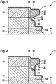
- Fig. 1 shows an asynchronous machine 10, which comprises a stator 12, a rotor 14 rotatably mounted in the stator 12 and a housing 16.
- the stator 12 is fastened to the housing 16, which in turn provides a bearing 18 in which the rotor 14 is mounted about an axis A by means of a shaft 20.
- the stator 12 has a winding head 22, which electrically connects windings or rods in the stator 12 to one another.
- the rotor 14 has a short-circuit ring 24 at the axial end, which electrically connects the short-circuit bars of the rotor to one another.
- the winding head 22 and the short-circuit ring 24 and the housing 16 are specially shaped.
- a wedge-shaped gap 26 is formed between them and is delimited by two inclined surfaces 28, 30. Both the gap 26 and the two inclined surfaces 28, 30 (which are inclined with respect to the axis A) run around the axis A.
- the inclined surface 28 is provided by the winding head 22, which has been wound accordingly, so that all of its conductors do not run in the region of the gap 26.
- the inclined surface 30 is provided by the short-circuit ring 24, which can have a smooth surface at the axial end in the circumferential direction in order to have the highest possible stray capacitance to the housing 16.
- the short-circuit ring 24 can also have specific bumps (such as a fan) to drive a cooling air flow.
- a section 32 of the housing 16 projects into the gap 26, which reinforces this effect.
- the section 32 is provided by a sheet metal part 34 which surrounds the stator 12 and the rotor 14 and which is supported by the bearing 18.
- the sheet metal part 34 runs in the radial direction past the short-circuit ring 24, runs in the radial direction and then in the axial direction around the winding head 22 and then in the axial direction around the stator 12.
- the sheet metal part 22 is deformed in a V-shape between the winding head 22 and the short-circuit ring 24 in order to form the section 32.
- an electrically conductive ring structure 33 can also be fastened to the stator 12, which projects beyond the stator package at the level of the inner radius of the stator 12.
- This ring structure 33 can be made of sheet metal, for example, or can be provided by grooving slides (protective foils for conductors inserted in the slots of the stator 12) on their outside.
- the housing 16 or the sheet metal part 34 can also run in the radial direction past the gap 26.
- a ring structure 36 can be fastened (for example welded or riveted), which projects into the gap 26 in order to increase the capacitance between the short-circuit ring 24 and the housing and the capacitance between the short-circuit ring 24 and the end winding 22 decrease.
- This ring structure 36 can either run uniformly around the entire circumference of the short-circuit ring 24 or else have lamellae 38 (see Fig. 3 ). Eddy currents can be reduced with lamellae 38 or a comb-shaped structure.
- lamellae 38 can be provided, which are bent in the direction of the axis or inwards. These fins 38 or wings can be tangential segments that have been punched out of the housing 16 or the sheet metal part 34.
- the angle of inclination of the ring structure 36 or the slats 38 against the axis A can also be very small (less than 10 °). In this way, their mounting location can then take place radially outward, for example just below the outer radius of the rotor 14.
- the inclined surface 30 of the short-circuit ring 24 can then also have a small angle of inclination with respect to the axis A (also less than 10 °).
- Fig. 3 shows an axial view and a cross section of fins 38, which can be provided, for example, on the ring structure 36 or punched out of the sheet metal part 36.
- the slats 38 can have a U-shape or V-shape and / or can have a reinforcement 40, for example a fold, in order to stabilize them mechanically.
Landscapes
- Engineering & Computer Science (AREA)
- Power Engineering (AREA)
- Physics & Mathematics (AREA)
- Electromagnetism (AREA)
- Insulation, Fastening Of Motor, Generator Windings (AREA)
Description
- Die Erfindung betrifft eine elektrische Asynchronmaschine, beispielsweise einen elektrischen Asynchronmotor, für ein Fahrzeug.
- Asynchronmaschinen umfassen in der Regel einen Stator, dessen Wicklungen über Wickelköpfe an den Enden des Stators geschlossen werden, und einen Rotor mit einem Rotorkäfig, dessen Kurzschlussstäbe mit Kurschlussringen an den Enden des Rotors miteinander elektrisch verbunden sind. Die Wickelköpfe und die Kurzschlussringe liegen normalerweise direkt nebeneinander, so dass zwischen ihnen eine kapazitative Kopplung auftreten kann. Über diese Kopplung können elektrische Ladungen auf dem Rotor influenziert werden, die über die Welle des Rotors, die elektrisch mit dem Rotor gekoppelt ist, zu elektromagnetischen Störungen außerhalb der Asynchronmaschine führen können.
Bei Asynchronmaschinen werden die Wickelköpfe, die Kurzschlussringe und die Form des Gehäuses in der Regel nach mechanischen und magnetischen, aber nicht nach Gesichtspunkten unerwünschter kapazitiver Überkopplung entworfen. - Die
DE 102 30 006 A1 zeigt ein Beispiel einer Asynchronmaschine mit einem Käfigläuferrotor, dessen Kurzschlussstäbe über zwei Kurschlussringe miteinander elektrisch verbunden sind. - Aus den Patentschriften
EP 0 236 690 A2 ,GB 807 967 A US 3 242 361 A sind elektrische Asynchronmaschinen bekannt, bei denen zwischen dem Wickelkopf und dem Kurzschlussring ein die Achse des Rotors umlaufender keilförmiger Spalt ausgebildet ist.
Aus den PatentschriftenUS 5 979 087 A ,GB 571 896 A US 6 011 338 A ,US 2001/005106 A1 ,DE 10 2011 078428 A1 undUS 2012/112571 A1 sind Asynchronmaschinen bekannt, bei denen im keilförmigen Spalt ein elektrisch leitfähiger, mit dem Gehäuse elektrisch verbundener Körper angeordnet ist. - Ausführungsformen der vorliegenden Erfindung können in vorteilhafter Weise ermöglichen, die elektromagnetische Verträglichkeit (EMV) einer Asynchronmaschine zu verbessern.
- Die Erfindung betrifft eine elektrische Asynchronmaschine, beispielsweise den Antrieb eines Elektro- und Hybridfahrzeugs, wie etwa eines Pkws, Lkws oder Busses.
- Gemäß einer Ausführungsform der Erfindung umfasst die Asynchronmaschine einen Stator mit wenigstens einem Wickelkopf an einem axialen Ende des Stators, ein Gehäuse, in dem der Stator befestigt ist, und einen im Gehäuse um eine Achse drehbar gelagerten Rotor, der einen Rotorkäfig aufweist, in dem durch den Stator Magnetfelder induzierbar sind, wobei der Rotorkäfig an wenigstens einem axialen Ende einen Kurzschlussring aufweist. Weiter ist zwischen dem Wickelkopf und dem Kurzschlussring ein die Achse des Rotors umlaufender keilförmiger Spalt ausgebildet, so dass eine kapazitative Kopplung zwischen dem Wickelkopf und dem Kurzschlussring vermindert ist.
- Mit anderen Worten können der Kurzschlussring und/oder der Wickelkopf derart ausgestaltet bzw. angeordnet sein, dass einerseits die elektrischen Leiter im Stator und im Rotor möglichst nahe beieinander angeordnet sind, um hier eine möglichst starke magnetische Kopplung zu erreichen, aber andererseits die elektrischen Leiter des Wickelkopfes und des Kurzschlussrings auseinander geführt werden, so dass in diesem Bereich nur eine geringe elektrostatische Kopplung erfolgt.
- Auf diese Weise kann die durch kapazitive Überkopplung zwischen dem Wickelkopf und dem Rotor induzierte Wechselspannung (die sogenannte Wellenspannung) in Bezug auf die effektiv wirksame Kapazität zwischen Phasenanschlüssen und der Welle reduziert werden. Der Wickelkopf induziert nur eine geringe Wechselspannung im Kurzschlussring bzw. im Rotor und der aus dem Gehäuse führenden Welle des Rotors. Auf diese Weise gelangen nur kleine elektrische Störfelder, die auf die Weise erzeugt werden, aus der elektrischen Maschine in deren Umgebung.
- Zwischen dem Kurzschlussring und dem Wickelkopf können somit große Abstände und kleine gegenüberliegende Flächen vorgesehen sein. Um die Kapazität zwischen dem Rotor bzw. dem Kurzschlussring und dem Gehäuse zu erhöhen, können umgekehrt kleine Abstände und große gegenüberliegende Flächen zwischen dem Rotor bzw. dem Kurzschlussring und dem Gehäuse vorgesehen sein.
- Gemäß einer Ausführungsform der Erfindung ist der Kurschlussring gegenüber der Achse des Rotors abgeschrägt und kann zur Bildung des keilförmigen Spalts eine Schrägfläche aufweisen. Diese (erste) Schrägfläche kann beispielsweise von der Achse weg weisen und eine erste, weiter innen liegende Seitenfläche des keilförmigen Spalts bilden.
- Gemäß einer Ausführungsform der Erfindung ist der Wickelkopf gegenüber der Achse des Rotors abgeschrägt und kann zur Bildung des keilförmigen Spalts eine Schrägfläche aufweisen. Diese zweite Schrägfläche kann beispielsweise zu der Achse hin weisen und/oder eine zweite, weiter außen liegende Seitenfläche des keilförmigen Spalts bilden.
- Erfindungsgemäß ist im keilförmigen Spalt ein elektrisch leitfähiger, mit dem Gehäuse elektrisch verbundener Körper angeordnet, um die kapazitative Kopplung zwischen dem Wickelkopf und dem Kurzschlussring zu vermindern und/oder die kapazitative Kopplung des Gehäuses mit dem Kurzschlussring zu erhöhen. Dieser elektrisch leitfähige Körper ist aus dem Material des Gehäuses (beispielsweise durch einen tiefgezogenen Abschnitt des Gehäuses) bereitgestellt.
- Der mit dem Gehäuse elektrisch verbundene Körper zwischen dem Kurzschlussring und dem Wickelkopf kann als elektrische Abschirmung zwischen Kurzschlussring und Wickelkopf aufgefasst werden.
- Die kapazitative Kopplung zwischen Wickelkopf, Kurzschlussring und Gehäuse kann somit durch eine besondere Formgestaltung von Wickelkopf, Kurzschlussring und Gehäuse im axialen Endbereich von Stator und Rotor eingestellt werden. Die Formgestaltung kann darauf abzielen, eine möglichst kleine Streukapazität zwischen dem Kurzschlussring und dem Wickelkopf und eine möglichst große Streukapazität zwischen Kurzschlussring und Gehäuse zu erhalten. Dadurch kann eine kapazitive Spannungsteilung und somit eine Reduktion der Wellenspannung erreicht werden.
- Gemäß einer Ausführungsform der Erfindung ragt das Gehäuse in den keilförmigen Spalt hinein. Beispielsweise kann das Gehäuse ein Blechteil umfassen, das den Rotor und den Stator stirnseitig (in axialer Richtung) umgibt und das den Stator auch radial außen umgeben kann. Dieses Blechteil ist erfindungsgemäß in einem Abschnitt derart verformt (beispielsweise durch Pressen oder Tiefziehen), dass es in den keilförmigen Spalt hineinragt.
- Dabei können zu beachtende Randbedingungen sein, dass eine hinreichende Kühlung, beispielsweise durch ein Fluid, das den Rotor und den Stator umspült, gewährleistet ist, und/oder dass unerwünschter magnetischer Streufluss im Bereich des Wickelkopfes begrenzt wird. Aus diesen Gründen kann es gewünscht sein, den Abstand von dem Kurzschlussring zu dem Gehäuse nicht wesentlich unter 2 mm abzusenken. Zur Begrenzung des unerwünschten magnetischen Streuflusses kann das Gehäuse bzw. das Blechteil aus Aluminium gefertigt sein.
- Gemäß einer Ausführungsform der Erfindung weist das Gehäuse einen V-förmig verformten Abschnitt auf, der in den keilförmigen Spalt hineinragt. Das Gehäuse kann (bis auf einen kleinen Abstand) komplementär zum keilförmigen Spalt geformt sein.
- Gemäß einer Ausführungsform der Erfindung weist das Gehäuse Lamellen auf, die aus dem Gehäuse in den keilförmigen Spalt hinein gebogen sind. Beispielsweise können im Blechteil des Gehäuses U- bzw. V-förmige Schlitze vorgesehen sein, die Lamellen bilden, die in Richtung der Achse gebogen werden können. In diesem Fall kann das Gehäuse am Kurzschlussring radial nach außen weitergeführt werden (wobei es zumindest teilweise nicht in den keilförmigen Spalt hineingeführt wird). Es kann somit tangentiale Fenster aufweisen, die beispielsweise aus dem Blechteil ausgestanzt sind und schräg nach innen gebogen sind. Auf diese Weise kann eine Struktur von abwechselnden Fenstern und Stegen im Blechteil entstehen.
- Gemäß einer Ausführungsform der Erfindung ist am Gehäuse eine elektrisch leitfähige Ringstruktur befestigt, die in den keilförmigen Spalt hineinragt. Es ist auch möglich, dass ein Blechteil des Gehäuses außerhalb des Spalts am Rotor vorbeigeführt wird, wobei ein mit dem Blechteil verbundenes weiteres Blechteil in den keilförmigen Spalt hineinragt. Die leitfähige Ringstruktur bzw. das weitere Blechteil kann genauso wie das Gehäuse aus Aluminium gefertigt sein. Auf diese Weise kann (aufgrund der fehlenden Fenster) mehr Drehmoment vom Stator über das Gehäuse übertragen werden).
- Gemäß einer Ausführungsform der Erfindung weist die Ringstruktur Lamellen auf, die in den keilförmigen Spalt hineinragen. Zur Verringerung von Wirbelströmen kann die leitfähige Ringstruktur eine kammähnliche Struktur aufweisen. Zur Erreichung der geforderten Schwingfestigkeit kann es eine Mindestdicke und/oder versteifende Falze aufweisen.
- Gemäß einer Ausführungsform der Erfindung ist am Stator eine elektrisch leitfähige Ringstruktur befestigt, die vom Stator aus in den keilförmigen Spalt hineinragt. Diese (zweite) leitfähige Ringstruktur kann beispielsweise ein am Stator befestigtes Blech oder ein Blechring sein. Sie kann auch von einem sogenannten Nutschieber gebildet sein, d.h. einer Schutzfolie, die zwischen die Leiter im Stator und/oder dem Statorblechpaket geschoben wird, die auf der dem Rotor zugewandten Seite mit einer leitfähigen Schicht überzogen werden kann. Eine derartige Schutzfolie ist in der Regel bereits vorhanden und kann derart eingefügt werden, dass sie über das Statorpaket (das Nuten für die Leiter im Stator bereitstellt) in axialer Richtung hinausragt.
- Es ist zu verstehen, dass diese Ausgestaltung des Wickelkopfes, des Kurzschlussrings und des Gehäuses nicht nur auf einer Seite, sondern auf beiden Seiten der Asynchronmaschine erfolgen kann.
- Es wird darauf hingewiesen, dass einige der möglichen Merkmale und Vorteile der Erfindung hierin mit Bezug auf unterschiedliche Ausführungsformen beschrieben sind. Ein Fachmann erkennt, dass die Merkmale in geeigneter Weise kombiniert, angepasst oder ausgetauscht werden können, um zu weiteren Ausführungsformen der Erfindung zu gelangen.
- Nachfolgend werden Ausführungsformen der Erfindung unter Bezugnahme auf die beigefügten Zeichnungen beschrieben, wobei weder die Zeichnungen noch die Beschreibung als die Erfindung einschränkend auszulegen sind.
-
Fig. 1 zeigt einen schematischen Längsschnitt durch eine Asynchronmaschine gemäß einer Ausführungsform der Erfindung. -
Fig. 2 zeigt einen schematischen Längsschnitt durch eine Asynchronmaschine gemäß einer weiteren Ausführungsform der Erfindung. -
Fig. 3 zeigt eine schematische Ansicht von Lamellen, die an einem Gehäuse einer Asynchronmaschine gemäß einer Ausführungsform der Erfindung vorgesehen sind. - Die Figuren sind lediglich schematisch und nicht maßstabsgetreu. Gleiche Bezugszeichen bezeichnen in den Figuren gleiche oder gleichwirkende Merkmale.
-
Fig. 1 zeigt eine Asynchronmaschine 10, die einen Stator 12, einen im Stator 12 rotierbar gelagerten Rotor 14 und ein Gehäuse 16 umfasst. Der Stator 12 ist am Gehäuse 16 befestigt, das wiederum ein Lager 18 bereitstellt, in dem der Rotor 14 mittels einer Welle 20 um eine Achse A gelagert ist. - Am axialen Ende (bezüglich der Achse A) weist der Stator 12 einen Wickelkopf 22 auf, der Wicklungen oder Stäbe im Stator 12 elektrisch miteinander verbindet. Ebenso weist der Rotor 14 am axialen Ende einen Kurzschlussring 24 auf, der die Kurzschlussstäbe des Rotors elektrisch miteinander verbindet.
- Um den Wickelkopf 22 und den Kurzschlussring 24 möglichst gut voneinander elektrostatisch zu entkoppeln, sind der Wickelkopf 22, der Kurzschlussring 24 und das Gehäuse 16 besonders geformt. Zwischen ihnen ist ein keilförmiger Spalt 26 gebildet, der von zwei Schrägflächen 28, 30 begrenzt wird. Sowohl der Spalt 26 als auch die beiden Schrägflächen 28, 30 (die bezüglich der Achse A schräg verlaufen) umlaufen die Achse A.
- Die Schrägfläche 28 wird durch den Wickelkopf 22 bereitgestellt, der entsprechend gewickelt wurde, so dass alle seine Leiter nicht im Bereich des Spalts 26 verlaufen.
- Die Schrägfläche 30 wird vom Kurzschlussring 24 bereitgestellt, der am axialen Ende in Umfangsrichtung gesehen eine glatte Oberfläche aufweisen kann, um eine möglichst hohe Streukapazität zum Gehäuse 16 aufzuweisen. Der Kurzschlussring 24 kann aber auch gezielte Unebenheiten (wie ein Lüfter) besitzen, um einen Kühlluftstrom anzutreiben.
- Da sich die beiden Schrägflächen 28, 30 in axialer Richtung von der elektrischen Maschine 10 weg voneinander entfernen, ist die elektrische Kapazität zwischen ihnen bereits niedriger, als wenn sie parallel verlaufen würden. Zusätzlich ragt ein Abschnitt 32 des Gehäuses 16 in den Spalt 26 hinein, der diesen Effekt verstärkt. Der Abschnitt 32 wird von einem Blechteil 34 bereitgestellt, das den Stator 12 und den Rotor 14 umgibt und das von dem Lager 18 getragen wird. Das Blechteil 34 verläuft in radialer Richtung am Kurzschlussring 24 vorbei, verläuft in radialer Richtung und anschließend in axialer Richtung um den Wickelkopf 22 und dann in axialer Richtung um den Stator 12.
- Zwischen dem Wickelkopf 22 und dem Kurzschlussring 24 ist das Blechteil 22 V-förmig verformt, um den Abschnitt 32 zu bilden.
- Weiter kann auch eine elektrisch leitende Ringstruktur 33 am Stator 12 befestigt sein, die auf Höhe des Innenradius des Stators 12 über das Statorpaket hinausragt. Diese Ringstruktur 33 kann beispielsweise aus Blech gefertigt sein oder kann dadurch bereitgestellt werden, dass Nutschieber (Schutzfolien für in Nuten des Stators 12 gesteckte Leiter) auf ihrer Außenseite metallisch beschichtet werden.
- Wie aus der
Fig. 2 hervorgeht, kann das Gehäuse 16 bzw. das Blechteil 34 auch in radialer Richtung am Spalt 26 vorbei verlaufen. Innen am Gehäuse bzw. am Blechteil 34 kann eine Ringstruktur 36 befestigt (beispielsweise geschweißt oder genietet) sein, die in den Spalt 26 hineinragt, um die Kapazität zwischen dem Kurzschlussring 24 und dem Gehäuse zu erhöhen und die Kapazität zwischen dem Kurzschlussring 24 und dem Wickelkopf 22 zu vermindern. Diese Ringstruktur 36 kann entweder gleichförmig um den gesamten Umfang des Kurzschlussrings 24 verlaufen oder aber auch Lamellen 38 aufweisen (sieheFig. 3 ). Mit Lamellen 38 bzw. einer kammförmigen Struktur können Wirbelströme vermindert werden. - Alternativ dazu können in dem Gehäuse 16 bzw. dem Blechteil 34 Lamellen 38 vorgesehen sein, die in Richtung der Achse bzw. nach innen gebogen sind. Diese Lamellen 38 oder Flügel können tangentiale Segmente sein, die aus dem Gehäuse 16 bzw. dem Blechteil 34 ausgestanzt worden sind.
- Der Neigungswinkel der Ringstruktur 36 bzw. der Lamellen 38 gegen die Achse A kann auch sehr klein sein (weniger als 10°). Auf diese Weise kann deren Anbringungsort dann weiter radial außen, beispielsweise knapp unter dem Außenradius des Rotors 14, erfolgen. Die Schrägfläche 30 des Kurzschlussrings 24 kann dann auch einen geringen Neigungswinkel gegenüber der Achse A aufweisen (auch weniger als 10°).
-
Fig. 3 zeigt eine axiale Sicht und einen Querschnitt von Lamellen 38, die beispielsweise an der Ringstruktur 36 vorgesehen oder aus dem Blechteil 36 ausgestanzt sein können. Die Lamellen 38 können eine U-Form oder V-Form aufweisen und/oder können eine Verstärkung 40 aufweisen, beispielsweise einen Falz, um sie mechanisch zu stabilisieren. - Abschließend ist darauf hinzuweisen, dass Begriffe wie "aufweisend", "umfassend" etc. keine anderen Elemente oder Schritte ausschließen und Begriffe wie "eine" oder "ein" keine Vielzahl ausschließen. Ferner sei darauf hingewiesen, dass Merkmale oder Schritte, die mit Verweis auf eines der obigen Ausführungsbeispiele beschrieben worden sind, auch in Kombination mit anderen Merkmalen oder Schritten anderer oben beschriebener Ausführungsbeispiele verwendet werden können.
- Die obige Beschreibung dient ausschließlich der Erläuterung der vorliegenden Erfindung. Der Schutzumfang der vorliegenden Erfindung soll hingegen ausschließlich durch die beigefügten Ansprüche bestimmt sein.
- Bezugszeichen in den Ansprüchen sind nicht als Einschränkung anzusehen.
Claims (8)
- Elektrische Asynchronmaschine (10), umfassend:einen Stator (12) mit wenigstens einem Wickelkopf (22) an einem axialen Ende des Stators (12);ein Gehäuse (16), in dem der Stator (12) befestigt ist;einen im Gehäuse (16) um eine Achse (A) drehbar gelagerten Rotor (14), in dem durch den Stator (12) Magnetfelder induzierbar sind, wobei der Rotor (14) an einem axialen Ende einen Kurzschlussring (30) aufweist;wobei zwischen dem Wickelkopf (22) und dem Kurzschlussring (24) ein die Achse (A) des Rotors (14) umlaufender keilförmiger Spalt (26) ausgebildet ist, so dass eine kapazitative Kopplung zwischen dem Wickelkopf (22) und dem Kurzschlussring (24) vermindert ist in Bezug auf einen fiktiven parallelen Verlauf von Wickelkopf (22) und Kurzschlussring (24), dadurch gekennzeichnet, dassim keilförmigen Spalt (26) ein elektrisch leitfähiger, mit dem Gehäuse (16) elektrisch verbundener Körper (32, 36, 33) angeordnet ist, um die kapazitative Kopplung zwischen dem Wickelkopf (22) und dem Kurzschlussring (24) zu vermindern und/oder die kapazitative Kopplung des Gehäuses (16) mit dem Kurzschlussring (24) zu erhöhen, wobei das Gehäuse (16) einen verformten Abschnitt (32) aufweist, der in den keilförmigen Spalt (26) hineinragt.
- Elektrische Asynchronmaschine (10) nach Anspruch 1,
wobei der Kurschlussring (24) gegenüber der Achse (A) des Rotors (14) abgeschrägt ist und zur Bildung des keilförmigen Spalts (26) eine Schrägfläche (30) aufweist. - Elektrische Asynchronmaschine (10) nach Anspruch 1 oder 2,
wobei der Wickelkopf (22) gegenüber der Achse (A) des Rotors (14) abgeschrägt ist und zur Bildung des keilförmigen Spalts (26) eine Schrägfläche (30) aufweist. - Elektrische Asynchronmaschine (10) nach einem der vorhergehenden Ansprüche,
wobei das Gehäuse (16) in den keilförmigen Spalt (26) hineinragt. - Elektrische Asynchronmaschine (10) nach einem der vorhergehenden Ansprüche,
wobei das Gehäuse (16) Lamellen aufweist, die aus dem Gehäuse (16) in den keilförmigen Spalt (26) hinein gebogen sind. - Elektrische Asynchronmaschine (10) nach einem der vorhergehenden Ansprüche,
wobei am Gehäuse (16) eine elektrisch leitfähige Ringstruktur (36) befestigt ist, die in den keilförmigen Spalt hineinragt. - Elektrische Asynchronmaschine (10) nach Anspruch 6,
wobei die Ringstruktur (36) Lamellen (38) aufweist, die in den keilförmigen Spalt (26) hineinragen. - Elektrische Asynchronmaschine (10) nach einem der vorhergehenden Ansprüche,
wobei am Stator (12) eine elektrisch leitfähige Ringstruktur (33) befestigt ist, die vom Stator (12) aus in den keilförmigen Spalt (26) hineinragt.
Applications Claiming Priority (2)
| Application Number | Priority Date | Filing Date | Title |
|---|---|---|---|
| DE102014222123.4A DE102014222123A1 (de) | 2014-10-29 | 2014-10-29 | Elektrische Asynchronmaschine |
| PCT/EP2015/069927 WO2016066302A2 (de) | 2014-10-29 | 2015-09-01 | Elektrische asynchronmaschine |
Publications (2)
| Publication Number | Publication Date |
|---|---|
| EP3213396A2 EP3213396A2 (de) | 2017-09-06 |
| EP3213396B1 true EP3213396B1 (de) | 2020-04-29 |
Family
ID=54185929
Family Applications (1)
| Application Number | Title | Priority Date | Filing Date |
|---|---|---|---|
| EP15767436.7A Active EP3213396B1 (de) | 2014-10-29 | 2015-09-01 | Elektrische asynchronmaschine |
Country Status (3)
| Country | Link |
|---|---|
| EP (1) | EP3213396B1 (de) |
| DE (1) | DE102014222123A1 (de) |
| WO (1) | WO2016066302A2 (de) |
Citations (9)
| Publication number | Priority date | Publication date | Assignee | Title |
|---|---|---|---|---|
| GB571896A (en) * | 1943-11-19 | 1945-09-13 | Scophony Ltd | Improvements in or relating to electric induction motors |
| GB807967A (en) * | 1956-06-13 | 1959-01-28 | Gen Electric | Improvements in or relating to induction motors |
| US3242361A (en) * | 1962-09-18 | 1966-03-22 | Allis Chalmers Mfg Co | High frequency induction motor |
| EP0236690A2 (de) * | 1986-03-10 | 1987-09-16 | Ipari Müszergyár | Elektrische rotierende Maschine |
| US5979087A (en) * | 1998-01-16 | 1999-11-09 | Reliance Electric Industrial Company | Electric motor having electrostatic shield arrangement |
| US6011338A (en) * | 1998-07-10 | 2000-01-04 | Reliance Electric Industrial Company | Electric motor having auxiliary winding arrangement for electrostatic shielding |
| US20010005106A1 (en) * | 1998-01-16 | 2001-06-28 | Sidney Bell | Electric motor having electrostatic shield arrangement |
| US20120112571A1 (en) * | 2010-11-09 | 2012-05-10 | General Electric Company | Encapsulated stator assembly |
| DE102011078428A1 (de) * | 2011-06-30 | 2013-01-03 | Siemens Aktiengesellschaft | Elektrische Maschine mit Lagerspannungsunterdrückung |
Family Cites Families (1)
| Publication number | Priority date | Publication date | Assignee | Title |
|---|---|---|---|---|
| DE10230006A1 (de) * | 2002-07-04 | 2004-01-29 | Robert Bosch Gmbh | Asynchronmaschine |
-
2014
- 2014-10-29 DE DE102014222123.4A patent/DE102014222123A1/de not_active Withdrawn
-
2015
- 2015-09-01 EP EP15767436.7A patent/EP3213396B1/de active Active
- 2015-09-01 WO PCT/EP2015/069927 patent/WO2016066302A2/de not_active Ceased
Patent Citations (9)
| Publication number | Priority date | Publication date | Assignee | Title |
|---|---|---|---|---|
| GB571896A (en) * | 1943-11-19 | 1945-09-13 | Scophony Ltd | Improvements in or relating to electric induction motors |
| GB807967A (en) * | 1956-06-13 | 1959-01-28 | Gen Electric | Improvements in or relating to induction motors |
| US3242361A (en) * | 1962-09-18 | 1966-03-22 | Allis Chalmers Mfg Co | High frequency induction motor |
| EP0236690A2 (de) * | 1986-03-10 | 1987-09-16 | Ipari Müszergyár | Elektrische rotierende Maschine |
| US5979087A (en) * | 1998-01-16 | 1999-11-09 | Reliance Electric Industrial Company | Electric motor having electrostatic shield arrangement |
| US20010005106A1 (en) * | 1998-01-16 | 2001-06-28 | Sidney Bell | Electric motor having electrostatic shield arrangement |
| US6011338A (en) * | 1998-07-10 | 2000-01-04 | Reliance Electric Industrial Company | Electric motor having auxiliary winding arrangement for electrostatic shielding |
| US20120112571A1 (en) * | 2010-11-09 | 2012-05-10 | General Electric Company | Encapsulated stator assembly |
| DE102011078428A1 (de) * | 2011-06-30 | 2013-01-03 | Siemens Aktiengesellschaft | Elektrische Maschine mit Lagerspannungsunterdrückung |
Also Published As
| Publication number | Publication date |
|---|---|
| EP3213396A2 (de) | 2017-09-06 |
| DE102014222123A1 (de) | 2016-05-04 |
| WO2016066302A3 (de) | 2016-06-23 |
| WO2016066302A2 (de) | 2016-05-06 |
Similar Documents
| Publication | Publication Date | Title |
|---|---|---|
| EP3105839B1 (de) | Luftfahrzeug mit einer synchronreluktanzmaschine | |
| DE102004003146B4 (de) | Motor, Kraftstoffpumpe, Kommutator und Verfahren zur Herstellung eines Kommutators | |
| EP3248271B1 (de) | Rotor einer asynchronmaschine | |
| EP3542445B1 (de) | Optimierte elektrische maschine | |
| DE112013001733T5 (de) | Statorkonstruktion für rotierende elektrische Maschine | |
| DE102009045101A1 (de) | Elektrische Maschine mit minimiertem Rastmoment | |
| EP2989711B1 (de) | Luftgekühlte elektrische maschine mit kühlrippen aus statorblech | |
| EP2770616A1 (de) | Elektrische Maschine mit geteiltem Stator | |
| DE102009034587A1 (de) | Rotierende elektrische Maschine für Fahrzeuge | |
| DE102012100332A1 (de) | Stator für eine rotierende elektrische Maschine und Verfahren zu seiner Herstellung | |
| DE102010043970A1 (de) | Elektrische Maschine für einen Lenkantrieb | |
| EP3012945B1 (de) | Elektrische maschine mit einem gehäuse | |
| EP3205004B1 (de) | Käfigläufer für eine elektrische asynchronmaschine mit einen kurzschlussring stabilisierender stützscheibe | |
| WO2019076543A1 (de) | Stator und elektrische maschine mit stator | |
| EP3602738A1 (de) | Polschuh, elektrische maschine und fahrzeug | |
| EP2652862B1 (de) | Maschinenkomponente für eine elektrische maschine | |
| WO2016066302A2 (de) | Elektrische asynchronmaschine | |
| DE102015219488A1 (de) | Elektrischer Antriebsmotor | |
| EP3185405B1 (de) | Elektromotor | |
| DE102009029472A1 (de) | Permanentmagneterregte elektrische Maschine mit reduziertem Lastmoment | |
| DE102009020327A1 (de) | Resolver | |
| DE102014210541A1 (de) | Hybriderregte elektrische Maschine | |
| DE102015007586B4 (de) | Energieübertragungseinrichtung sowie eine elektrische Maschine mit einer Energieübertragungseinrichtung | |
| DE112024002992T5 (de) | Spule und elektrische drehmaschine | |
| EP3084926B1 (de) | Rotor einer rotierenden elektrischen maschine |
Legal Events
| Date | Code | Title | Description |
|---|---|---|---|
| STAA | Information on the status of an ep patent application or granted ep patent |
Free format text: STATUS: THE INTERNATIONAL PUBLICATION HAS BEEN MADE |
|
| PUAI | Public reference made under article 153(3) epc to a published international application that has entered the european phase |
Free format text: ORIGINAL CODE: 0009012 |
|
| STAA | Information on the status of an ep patent application or granted ep patent |
Free format text: STATUS: REQUEST FOR EXAMINATION WAS MADE |
|
| 17P | Request for examination filed |
Effective date: 20170529 |
|
| AK | Designated contracting states |
Kind code of ref document: A2 Designated state(s): AL AT BE BG CH CY CZ DE DK EE ES FI FR GB GR HR HU IE IS IT LI LT LU LV MC MK MT NL NO PL PT RO RS SE SI SK SM TR |
|
| AX | Request for extension of the european patent |
Extension state: BA ME |
|
| DAV | Request for validation of the european patent (deleted) | ||
| DAX | Request for extension of the european patent (deleted) | ||
| STAA | Information on the status of an ep patent application or granted ep patent |
Free format text: STATUS: EXAMINATION IS IN PROGRESS |
|
| 17Q | First examination report despatched |
Effective date: 20190621 |
|
| REG | Reference to a national code |
Ref country code: DE Ref legal event code: R079 Ref document number: 502015012450 Country of ref document: DE Free format text: PREVIOUS MAIN CLASS: H02K0005000000 Ipc: H02K0005040000 |
|
| GRAP | Despatch of communication of intention to grant a patent |
Free format text: ORIGINAL CODE: EPIDOSNIGR1 |
|
| STAA | Information on the status of an ep patent application or granted ep patent |
Free format text: STATUS: GRANT OF PATENT IS INTENDED |
|
| RIC1 | Information provided on ipc code assigned before grant |
Ipc: H02K 11/01 20160101ALI20200106BHEP Ipc: H02K 5/04 20060101AFI20200106BHEP Ipc: H02K 11/40 20160101ALI20200106BHEP Ipc: H02K 17/16 20060101ALI20200106BHEP |
|
| INTG | Intention to grant announced |
Effective date: 20200124 |
|
| GRAS | Grant fee paid |
Free format text: ORIGINAL CODE: EPIDOSNIGR3 |
|
| GRAA | (expected) grant |
Free format text: ORIGINAL CODE: 0009210 |
|
| STAA | Information on the status of an ep patent application or granted ep patent |
Free format text: STATUS: THE PATENT HAS BEEN GRANTED |
|
| AK | Designated contracting states |
Kind code of ref document: B1 Designated state(s): AL AT BE BG CH CY CZ DE DK EE ES FI FR GB GR HR HU IE IS IT LI LT LU LV MC MK MT NL NO PL PT RO RS SE SI SK SM TR |
|
| RAP1 | Party data changed (applicant data changed or rights of an application transferred) |
Owner name: ROBERT BOSCH GMBH |
|
| REG | Reference to a national code |
Ref country code: GB Ref legal event code: FG4D Free format text: NOT ENGLISH |
|
| REG | Reference to a national code |
Ref country code: CH Ref legal event code: EP |
|
| REG | Reference to a national code |
Ref country code: AT Ref legal event code: REF Ref document number: 1264783 Country of ref document: AT Kind code of ref document: T Effective date: 20200515 |
|
| REG | Reference to a national code |
Ref country code: DE Ref legal event code: R096 Ref document number: 502015012450 Country of ref document: DE |
|
| REG | Reference to a national code |
Ref country code: IE Ref legal event code: FG4D Free format text: LANGUAGE OF EP DOCUMENT: GERMAN |
|
| REG | Reference to a national code |
Ref country code: NL Ref legal event code: MP Effective date: 20200429 |
|
| REG | Reference to a national code |
Ref country code: LT Ref legal event code: MG4D |
|
| PG25 | Lapsed in a contracting state [announced via postgrant information from national office to epo] |
Ref country code: IS Free format text: LAPSE BECAUSE OF FAILURE TO SUBMIT A TRANSLATION OF THE DESCRIPTION OR TO PAY THE FEE WITHIN THE PRESCRIBED TIME-LIMIT Effective date: 20200829 Ref country code: PT Free format text: LAPSE BECAUSE OF FAILURE TO SUBMIT A TRANSLATION OF THE DESCRIPTION OR TO PAY THE FEE WITHIN THE PRESCRIBED TIME-LIMIT Effective date: 20200831 Ref country code: FI Free format text: LAPSE BECAUSE OF FAILURE TO SUBMIT A TRANSLATION OF THE DESCRIPTION OR TO PAY THE FEE WITHIN THE PRESCRIBED TIME-LIMIT Effective date: 20200429 Ref country code: NO Free format text: LAPSE BECAUSE OF FAILURE TO SUBMIT A TRANSLATION OF THE DESCRIPTION OR TO PAY THE FEE WITHIN THE PRESCRIBED TIME-LIMIT Effective date: 20200729 Ref country code: SE Free format text: LAPSE BECAUSE OF FAILURE TO SUBMIT A TRANSLATION OF THE DESCRIPTION OR TO PAY THE FEE WITHIN THE PRESCRIBED TIME-LIMIT Effective date: 20200429 Ref country code: LT Free format text: LAPSE BECAUSE OF FAILURE TO SUBMIT A TRANSLATION OF THE DESCRIPTION OR TO PAY THE FEE WITHIN THE PRESCRIBED TIME-LIMIT Effective date: 20200429 Ref country code: GR Free format text: LAPSE BECAUSE OF FAILURE TO SUBMIT A TRANSLATION OF THE DESCRIPTION OR TO PAY THE FEE WITHIN THE PRESCRIBED TIME-LIMIT Effective date: 20200730 |
|
| PG25 | Lapsed in a contracting state [announced via postgrant information from national office to epo] |
Ref country code: BG Free format text: LAPSE BECAUSE OF FAILURE TO SUBMIT A TRANSLATION OF THE DESCRIPTION OR TO PAY THE FEE WITHIN THE PRESCRIBED TIME-LIMIT Effective date: 20200729 Ref country code: HR Free format text: LAPSE BECAUSE OF FAILURE TO SUBMIT A TRANSLATION OF THE DESCRIPTION OR TO PAY THE FEE WITHIN THE PRESCRIBED TIME-LIMIT Effective date: 20200429 Ref country code: LV Free format text: LAPSE BECAUSE OF FAILURE TO SUBMIT A TRANSLATION OF THE DESCRIPTION OR TO PAY THE FEE WITHIN THE PRESCRIBED TIME-LIMIT Effective date: 20200429 Ref country code: RS Free format text: LAPSE BECAUSE OF FAILURE TO SUBMIT A TRANSLATION OF THE DESCRIPTION OR TO PAY THE FEE WITHIN THE PRESCRIBED TIME-LIMIT Effective date: 20200429 |
|
| PG25 | Lapsed in a contracting state [announced via postgrant information from national office to epo] |
Ref country code: AL Free format text: LAPSE BECAUSE OF FAILURE TO SUBMIT A TRANSLATION OF THE DESCRIPTION OR TO PAY THE FEE WITHIN THE PRESCRIBED TIME-LIMIT Effective date: 20200429 Ref country code: NL Free format text: LAPSE BECAUSE OF FAILURE TO SUBMIT A TRANSLATION OF THE DESCRIPTION OR TO PAY THE FEE WITHIN THE PRESCRIBED TIME-LIMIT Effective date: 20200429 |
|
| PG25 | Lapsed in a contracting state [announced via postgrant information from national office to epo] |
Ref country code: DK Free format text: LAPSE BECAUSE OF FAILURE TO SUBMIT A TRANSLATION OF THE DESCRIPTION OR TO PAY THE FEE WITHIN THE PRESCRIBED TIME-LIMIT Effective date: 20200429 Ref country code: ES Free format text: LAPSE BECAUSE OF FAILURE TO SUBMIT A TRANSLATION OF THE DESCRIPTION OR TO PAY THE FEE WITHIN THE PRESCRIBED TIME-LIMIT Effective date: 20200429 Ref country code: RO Free format text: LAPSE BECAUSE OF FAILURE TO SUBMIT A TRANSLATION OF THE DESCRIPTION OR TO PAY THE FEE WITHIN THE PRESCRIBED TIME-LIMIT Effective date: 20200429 Ref country code: CZ Free format text: LAPSE BECAUSE OF FAILURE TO SUBMIT A TRANSLATION OF THE DESCRIPTION OR TO PAY THE FEE WITHIN THE PRESCRIBED TIME-LIMIT Effective date: 20200429 Ref country code: SM Free format text: LAPSE BECAUSE OF FAILURE TO SUBMIT A TRANSLATION OF THE DESCRIPTION OR TO PAY THE FEE WITHIN THE PRESCRIBED TIME-LIMIT Effective date: 20200429 Ref country code: EE Free format text: LAPSE BECAUSE OF FAILURE TO SUBMIT A TRANSLATION OF THE DESCRIPTION OR TO PAY THE FEE WITHIN THE PRESCRIBED TIME-LIMIT Effective date: 20200429 |
|
| REG | Reference to a national code |
Ref country code: DE Ref legal event code: R097 Ref document number: 502015012450 Country of ref document: DE |
|
| PG25 | Lapsed in a contracting state [announced via postgrant information from national office to epo] |
Ref country code: PL Free format text: LAPSE BECAUSE OF FAILURE TO SUBMIT A TRANSLATION OF THE DESCRIPTION OR TO PAY THE FEE WITHIN THE PRESCRIBED TIME-LIMIT Effective date: 20200429 Ref country code: SK Free format text: LAPSE BECAUSE OF FAILURE TO SUBMIT A TRANSLATION OF THE DESCRIPTION OR TO PAY THE FEE WITHIN THE PRESCRIBED TIME-LIMIT Effective date: 20200429 |
|
| PLBE | No opposition filed within time limit |
Free format text: ORIGINAL CODE: 0009261 |
|
| STAA | Information on the status of an ep patent application or granted ep patent |
Free format text: STATUS: NO OPPOSITION FILED WITHIN TIME LIMIT |
|
| 26N | No opposition filed |
Effective date: 20210201 |
|
| REG | Reference to a national code |
Ref country code: CH Ref legal event code: PL |
|
| GBPC | Gb: european patent ceased through non-payment of renewal fee |
Effective date: 20200901 |
|
| PG25 | Lapsed in a contracting state [announced via postgrant information from national office to epo] |
Ref country code: SI Free format text: LAPSE BECAUSE OF FAILURE TO SUBMIT A TRANSLATION OF THE DESCRIPTION OR TO PAY THE FEE WITHIN THE PRESCRIBED TIME-LIMIT Effective date: 20200429 |
|
| REG | Reference to a national code |
Ref country code: BE Ref legal event code: MM Effective date: 20200930 |
|
| PG25 | Lapsed in a contracting state [announced via postgrant information from national office to epo] |
Ref country code: LU Free format text: LAPSE BECAUSE OF NON-PAYMENT OF DUE FEES Effective date: 20200901 |
|
| PG25 | Lapsed in a contracting state [announced via postgrant information from national office to epo] |
Ref country code: BE Free format text: LAPSE BECAUSE OF NON-PAYMENT OF DUE FEES Effective date: 20200930 Ref country code: CH Free format text: LAPSE BECAUSE OF NON-PAYMENT OF DUE FEES Effective date: 20200930 Ref country code: IE Free format text: LAPSE BECAUSE OF NON-PAYMENT OF DUE FEES Effective date: 20200901 Ref country code: GB Free format text: LAPSE BECAUSE OF NON-PAYMENT OF DUE FEES Effective date: 20200901 Ref country code: LI Free format text: LAPSE BECAUSE OF NON-PAYMENT OF DUE FEES Effective date: 20200930 |
|
| REG | Reference to a national code |
Ref country code: AT Ref legal event code: MM01 Ref document number: 1264783 Country of ref document: AT Kind code of ref document: T Effective date: 20200901 |
|
| PG25 | Lapsed in a contracting state [announced via postgrant information from national office to epo] |
Ref country code: AT Free format text: LAPSE BECAUSE OF NON-PAYMENT OF DUE FEES Effective date: 20200901 |
|
| PG25 | Lapsed in a contracting state [announced via postgrant information from national office to epo] |
Ref country code: TR Free format text: LAPSE BECAUSE OF FAILURE TO SUBMIT A TRANSLATION OF THE DESCRIPTION OR TO PAY THE FEE WITHIN THE PRESCRIBED TIME-LIMIT Effective date: 20200429 Ref country code: MT Free format text: LAPSE BECAUSE OF FAILURE TO SUBMIT A TRANSLATION OF THE DESCRIPTION OR TO PAY THE FEE WITHIN THE PRESCRIBED TIME-LIMIT Effective date: 20200429 Ref country code: CY Free format text: LAPSE BECAUSE OF FAILURE TO SUBMIT A TRANSLATION OF THE DESCRIPTION OR TO PAY THE FEE WITHIN THE PRESCRIBED TIME-LIMIT Effective date: 20200429 |
|
| PG25 | Lapsed in a contracting state [announced via postgrant information from national office to epo] |
Ref country code: MK Free format text: LAPSE BECAUSE OF FAILURE TO SUBMIT A TRANSLATION OF THE DESCRIPTION OR TO PAY THE FEE WITHIN THE PRESCRIBED TIME-LIMIT Effective date: 20200429 Ref country code: MC Free format text: LAPSE BECAUSE OF FAILURE TO SUBMIT A TRANSLATION OF THE DESCRIPTION OR TO PAY THE FEE WITHIN THE PRESCRIBED TIME-LIMIT Effective date: 20200429 |
|
| PGFP | Annual fee paid to national office [announced via postgrant information from national office to epo] |
Ref country code: FR Payment date: 20250922 Year of fee payment: 11 |
|
| PGFP | Annual fee paid to national office [announced via postgrant information from national office to epo] |
Ref country code: DE Payment date: 20251121 Year of fee payment: 11 |
|
| PGFP | Annual fee paid to national office [announced via postgrant information from national office to epo] |
Ref country code: IT Payment date: 20250930 Year of fee payment: 11 |