EP3213045B1 - Procédé et système pour la surveillance de l'intégrité des structures avec une synchronisation de fréquence - Google Patents
Procédé et système pour la surveillance de l'intégrité des structures avec une synchronisation de fréquence Download PDFInfo
- Publication number
- EP3213045B1 EP3213045B1 EP15801985.1A EP15801985A EP3213045B1 EP 3213045 B1 EP3213045 B1 EP 3213045B1 EP 15801985 A EP15801985 A EP 15801985A EP 3213045 B1 EP3213045 B1 EP 3213045B1
- Authority
- EP
- European Patent Office
- Prior art keywords
- signal
- structural component
- sensors
- deformation field
- actuator
- Prior art date
- Legal status (The legal status is an assumption and is not a legal conclusion. Google has not performed a legal analysis and makes no representation as to the accuracy of the status listed.)
- Active
Links
Images


Classifications
-
- G—PHYSICS
- G01—MEASURING; TESTING
- G01M—TESTING STATIC OR DYNAMIC BALANCE OF MACHINES OR STRUCTURES; TESTING OF STRUCTURES OR APPARATUS, NOT OTHERWISE PROVIDED FOR
- G01M7/00—Vibration-testing of structures; Shock-testing of structures
-
- G—PHYSICS
- G01—MEASURING; TESTING
- G01M—TESTING STATIC OR DYNAMIC BALANCE OF MACHINES OR STRUCTURES; TESTING OF STRUCTURES OR APPARATUS, NOT OTHERWISE PROVIDED FOR
- G01M5/00—Investigating the elasticity of structures, e.g. deflection of bridges or air-craft wings
- G01M5/0033—Investigating the elasticity of structures, e.g. deflection of bridges or air-craft wings by determining damage, crack or wear
-
- G—PHYSICS
- G01—MEASURING; TESTING
- G01L—MEASURING FORCE, STRESS, TORQUE, WORK, MECHANICAL POWER, MECHANICAL EFFICIENCY, OR FLUID PRESSURE
- G01L1/00—Measuring force or stress, in general
- G01L1/16—Measuring force or stress, in general using properties of piezoelectric devices
- G01L1/162—Measuring force or stress, in general using properties of piezoelectric devices using piezoelectric resonators
- G01L1/167—Measuring force or stress, in general using properties of piezoelectric devices using piezoelectric resonators optical excitation or measuring of vibrations
-
- G—PHYSICS
- G01—MEASURING; TESTING
- G01L—MEASURING FORCE, STRESS, TORQUE, WORK, MECHANICAL POWER, MECHANICAL EFFICIENCY, OR FLUID PRESSURE
- G01L1/00—Measuring force or stress, in general
- G01L1/24—Measuring force or stress, in general by measuring variations of optical properties of material when it is stressed, e.g. by photoelastic stress analysis using infrared, visible light, ultraviolet
- G01L1/242—Measuring force or stress, in general by measuring variations of optical properties of material when it is stressed, e.g. by photoelastic stress analysis using infrared, visible light, ultraviolet the material being an optical fibre
- G01L1/246—Measuring force or stress, in general by measuring variations of optical properties of material when it is stressed, e.g. by photoelastic stress analysis using infrared, visible light, ultraviolet the material being an optical fibre using integrated gratings, e.g. Bragg gratings
-
- G—PHYSICS
- G01—MEASURING; TESTING
- G01M—TESTING STATIC OR DYNAMIC BALANCE OF MACHINES OR STRUCTURES; TESTING OF STRUCTURES OR APPARATUS, NOT OTHERWISE PROVIDED FOR
- G01M5/00—Investigating the elasticity of structures, e.g. deflection of bridges or air-craft wings
- G01M5/0041—Investigating the elasticity of structures, e.g. deflection of bridges or air-craft wings by determining deflection or stress
-
- G—PHYSICS
- G01—MEASURING; TESTING
- G01M—TESTING STATIC OR DYNAMIC BALANCE OF MACHINES OR STRUCTURES; TESTING OF STRUCTURES OR APPARATUS, NOT OTHERWISE PROVIDED FOR
- G01M5/00—Investigating the elasticity of structures, e.g. deflection of bridges or air-craft wings
- G01M5/0066—Investigating the elasticity of structures, e.g. deflection of bridges or air-craft wings by exciting or detecting vibration or acceleration
-
- G—PHYSICS
- G01—MEASURING; TESTING
- G01N—INVESTIGATING OR ANALYSING MATERIALS BY DETERMINING THEIR CHEMICAL OR PHYSICAL PROPERTIES
- G01N29/00—Investigating or analysing materials by the use of ultrasonic, sonic or infrasonic waves; Visualisation of the interior of objects by transmitting ultrasonic or sonic waves through the object
- G01N29/04—Analysing solids
- G01N29/11—Analysing solids by measuring attenuation of acoustic waves
-
- G—PHYSICS
- G01—MEASURING; TESTING
- G01N—INVESTIGATING OR ANALYSING MATERIALS BY DETERMINING THEIR CHEMICAL OR PHYSICAL PROPERTIES
- G01N29/00—Investigating or analysing materials by the use of ultrasonic, sonic or infrasonic waves; Visualisation of the interior of objects by transmitting ultrasonic or sonic waves through the object
- G01N29/34—Generating the ultrasonic, sonic or infrasonic waves, e.g. electronic circuits specially adapted therefor
- G01N29/341—Generating the ultrasonic, sonic or infrasonic waves, e.g. electronic circuits specially adapted therefor with time characteristics
- G01N29/345—Generating the ultrasonic, sonic or infrasonic waves, e.g. electronic circuits specially adapted therefor with time characteristics continuous waves
-
- G—PHYSICS
- G01—MEASURING; TESTING
- G01N—INVESTIGATING OR ANALYSING MATERIALS BY DETERMINING THEIR CHEMICAL OR PHYSICAL PROPERTIES
- G01N29/00—Investigating or analysing materials by the use of ultrasonic, sonic or infrasonic waves; Visualisation of the interior of objects by transmitting ultrasonic or sonic waves through the object
- G01N29/34—Generating the ultrasonic, sonic or infrasonic waves, e.g. electronic circuits specially adapted therefor
- G01N29/348—Generating the ultrasonic, sonic or infrasonic waves, e.g. electronic circuits specially adapted therefor with frequency characteristics, e.g. single frequency signals, chirp signals
-
- G—PHYSICS
- G01—MEASURING; TESTING
- G01N—INVESTIGATING OR ANALYSING MATERIALS BY DETERMINING THEIR CHEMICAL OR PHYSICAL PROPERTIES
- G01N29/00—Investigating or analysing materials by the use of ultrasonic, sonic or infrasonic waves; Visualisation of the interior of objects by transmitting ultrasonic or sonic waves through the object
- G01N29/44—Processing the detected response signal, e.g. electronic circuits specially adapted therefor
- G01N29/4409—Processing the detected response signal, e.g. electronic circuits specially adapted therefor by comparison
- G01N29/4436—Processing the detected response signal, e.g. electronic circuits specially adapted therefor by comparison with a reference signal
-
- G—PHYSICS
- G01—MEASURING; TESTING
- G01N—INVESTIGATING OR ANALYSING MATERIALS BY DETERMINING THEIR CHEMICAL OR PHYSICAL PROPERTIES
- G01N2291/00—Indexing codes associated with group G01N29/00
- G01N2291/01—Indexing codes associated with the measuring variable
- G01N2291/012—Phase angle
-
- G—PHYSICS
- G01—MEASURING; TESTING
- G01N—INVESTIGATING OR ANALYSING MATERIALS BY DETERMINING THEIR CHEMICAL OR PHYSICAL PROPERTIES
- G01N2291/00—Indexing codes associated with group G01N29/00
- G01N2291/02—Indexing codes associated with the analysed material
- G01N2291/025—Change of phase or condition
- G01N2291/0258—Structural degradation, e.g. fatigue of composites, ageing of oils
-
- G—PHYSICS
- G01—MEASURING; TESTING
- G01N—INVESTIGATING OR ANALYSING MATERIALS BY DETERMINING THEIR CHEMICAL OR PHYSICAL PROPERTIES
- G01N2291/00—Indexing codes associated with group G01N29/00
- G01N2291/10—Number of transducers
- G01N2291/103—Number of transducers one emitter, two or more receivers
Definitions
- the technology herein relates to the field of structural health monitoring ("SHM”), and more specifically, to methods and systems for structural health monitoring of composite, metal or other structures, based on the measurement of the deformation field on the surface under test and comparison with an initial or otherwise known signature(s) of the (non-defective) structure through a scan of a frequency range and evaluation of the amplitude (or RMS value or peak-to-peak value) of different sensors near resonance(s).
- methods, apparatus and techniques provided by the present example non-limiting embodiment comprise or involve building deformation fields maps (amplitude and phase related to excitation) on the surface of the structural component under monitoring based on a network of strain measurements by fiber Bragg grating sensors.
- Some SHM systems use "passive" strain tracking or acoustic emission monitoring techniques.
- both passive strain tracking and passive acoustic emission monitoring techniques may require continuous monitoring. Accordingly, if a power failure or power shut-down occurs, the SHM system may be disabled - which can be a disadvantage.
- both passive strain tracking and passive acoustic emission monitoring may not be as sensitive as desired, and therefore may be less accurate and/or reliable.
- the accuracy and reliability of acoustic emission monitoring techniques may also be compromised by the generally noisy environment of a vehicle or other environment.
- Another possible disadvantage of acoustic emission monitoring is that a large amount of data storage may be necessary.
- the strain tracking technique may require a finite element strain distribution model with which to compare the measured strain distribution across the structure, possibly increasing development cost.
- SHM systems may be considered “active” systems because they use transducers to actively excite and sense vibrational characteristics of the structure.
- the vibrational characteristics can be compared with known or baseline (and thus predetermined) vibrational characteristics of a normal undamaged structure; and the difference(s) is used to determine the health of the structure.
- the vibrational characteristics can be defined by computing the transfer function between each actuator and sensor.
- the transfer functions can then be compared to a baseline reference representing a normal "healthy" state of the structure.
- the baseline may be generated by collecting several sets of actuator/sensor data when the structure is healthy, and computing statistical values such as the mean and standard deviation of the data sets.
- temperature variations of the structure may sometimes cause these active SHM systems to erroneously detect damage.
- temperature variations in the structure may cause variations in the measured vibrational characteristics that carry over into the transfer functions computed therefrom.
- Piezoceramic devices can be applied as actuators to generate the vibrational waves, and fiber optic cables with different grating locations can be used as sensors to catch or sense the propagating wave signals.
- a possible drawback of this type of system is that it cannot accommodate a large number of actuator arrays and, as a consequence, each of actuators and sensors must be placed individually. Since the damage detection is based on changes of vibrational waves traveling along line-of-sight paths between the actuators and sensors, such a method may fail to detect the damage located out of the paths and/or around the boundary of the structure.
- Such a conformal circuit may for example consist of a series of stacked layers and traces of strain sensors, where each sensor measures strain changes at its corresponding location to identify defects of a conformal structure.
- the conformal circuit may for example comprise a passive system, i.e., it does not have any actuator for generating signals.
- Another example passive sensory network system may use a piezoceramic-fiber sensory system having planer fibers embedded in a composite structure.
- the SMART Layer® includes piezoceramic sensors/actuators equidistantly placed and cured with flexible dielectric films sandwiching the piezoceramic sensors/actuators ("piezoceramics").
- the actuators generate acoustic waves and sensors receive/transform the acoustic waves into electric signals.
- metallic clad wires are etched using conventional flexible circuitry and laminated between the substrates. As a consequence, a considerable amount of the flexible substrate area may be needed to cover the clad wire regions.
- the SMART Layer@ may need to be cured with its host structure made of laminated composite layers. Due to the internal stress caused by a high temperature cycle during the curing process, the piezoceramics in the SMART Layer® can be micro-fractured. Also, the substrate of the SMART Layer@ can sometimes be easily separated from the host structure. Moreover, it can be very difficult to insert or attach the SMART Layer@ to its host structure having a curved section and, as a consequence, a compressive load applied to the curved section can sometimes easily fold the clad wires. Fractured piezoceramics and the folded wires may be susceptible to electromagnetic interference noise and provide misleading electrical signals.
- the SMART Layer@ may not necessarily be a robust and unreliable tool for monitoring structural health. Furthermore, the replacement of damaged and/or defective actuators/sensors may sometimes be costly as the host structure may need to be dismantled.
- piezo-ceramic actuators particularly for active vibration dampening and/or shape control purposes, as well as fiber Bragg grating sensors, particularly in the form of strain measurement sensors.
- the piezo-ceramic actuators are designed as piezo fiber modules and the fiber Bragg grating sensors are at least partially embedded in the piezo fiber modules.
- Yet another known interrogation systems for monitoring structural health conditions includes at least one wave generator for generating a wave signal and optical fiber sensors applied to a structure.
- the interrogation system also includes at least one electronic module for generating an input sensor signal and sending the input sensor signal to the optical fiber sensors. Each optical fiber sensor impresses the wave signal onto the input sensor signal to generate an output sensor signal that is frequency shifted from the input sensor signal.
- the electronic module generates an information signal in response to the output sensor signal.
- the interrogation system also includes a signal processing unit and a relay switches array module. Each relay switch relays the information signal to the signal processing unit and the signal processing unit generates a digital sensor signal that is subsequently sent to a computer.
- Yet another known method for monitoring damage to a structure having an actuator and a sensor includes exciting the actuator across a predetermined frequency range to excite the structure, measuring a vibrational characteristic of the structure across the predetermined frequency range in response to the excitation of the actuator using the sensor, calculating a transfer function for the actuator and the sensor using the measured vibrational characteristic, determining a change in the vibrational characteristic across the predetermined frequency range using the transfer function, and analyzing the determined change in the vibrational characteristic across the predetermined frequency range to facilitate determining whether the structure is damaged.
- optical fiber sensor includes a rolled optical fiber cable operative to generate a frequency shift of a light signal passing through the optical fiber and a coating layer applied to the rolled optical cable. The frequency shift is commensurate with vibration of the host structure.
- the electronic module sends an input light signal to the optical fiber sensor, receives a sensor signal from the optical fiber sensor, and processes the sensor signal.
- Yet another known method for optimizing transducer performance in an array of transducers in a structural health monitoring system includes specifying a plurality of paths between pairs of the transducers on a monitored structure and evaluating the quality of signal transmissions along the paths so as to optimize the gain and frequency operating condition of the transducers.
- At least one electromechanical transducer is fixed to a structure as an object of diagnosis and is driven with an alternating voltage of a constant amplitude, and a current flowing through the at least one electromechanical transducer is measured.
- high frequency components around a driving frequency of the electromechanical transducer are separated from a signal of the current.
- modulation information due to a damage is extracted from amplitude and/or phase demodulation of the high frequency components.
- a damage index is evaluated based on the modulation information.
- Yet another known method relates to testing structures or bodies to determine if they contain defects such as cracks or delamination.
- Such a method for testing a body comprises the steps of comparing first data, representing an excitation signal launched into the body to produce a guided wave within the body, with second data, derived from the body while bearing the guided wave, to identify a phase difference between the first and second data; and determining a measure of the structural integrity of the body using the phase difference. It is alleged that by basing the assessment of the structural body on defect induced phase modulation, more accurate testing can be performed.
- Another known structural health monitoring system for example a system used in the non-destructive evaluation of an aircraft structure provides a method and apparatus for evaluating one or more anomalies within a structure using a structural health monitoring system that includes at least three transducers arranged in operative contact with the structure such that no two transducers are aligned to be parallel.
- a transducer excites an elastic wave that propagates through the structure, and reflections from any anomalies within the structure are collected by the three transducers. These collected signals are analyzed to identify an anomaly within the structure. Time of flight techniques are used to determine the location of the anomaly.
- the present invention provides a method for monitoring the structural health of a component according to claim 1 and a respective system according to claim 5. Embodiments are defined in the dependent claims.
- Methods, apparatus and techniques provided by the present example non-limiting embodiments comprise or involve building deformation fields maps (amplitude and phase related to excitation) on the surface of the structural component under monitoring based on a network of strain measurements by fiber Bragg grating sensors.
- the mapped deformation fields are obtained from the excitation of the structural component by piezoelectric actuators attached to and/or embedded into the structural component.
- the signals captured by the optical sensors are filtered so as to measure only the deformations of the same frequency used for the excitation, that is, just the contribution to the field brought by the piezoelectric actuators.
- the so-obtained deformation maps are compared with a previously obtained standard or baseline map which is the structural component without any deformation or with a defect of known dimensions and positions.
- An artificial intelligence algorithm can be employed in some non-limiting embodiments so that based on the initial standard or baseline, it is possible to detect, locate and quantify new faults or failures or alternatively monitor the growth of any previously detected fault or damage.
- a method for monitoring damage to a structure having at least an actuator and at least a sensor.
- the method includes exciting in-phase or out-of-phase the at least one actuator or a group of actuators, or all the actuators using CW (continuous wave) across a predetermined frequency range to excite the structure, so as to generate a dynamic deformation field, with senoidal (sinusoidal) timed variation at the same frequency of the potential difference imposed on the piezoelectric elements.
- the deformation field superimposes on the already existing deformation field on the structural component caused by primary and secondary loads which act on the structural component, including those related to temperature.
- the choice of the frequency of actuation is made to be different from the frequency ranges associated with the primary and secondary loads as well as to temperature variations in the structural component.
- the measurement of the deformation field can then be filtered so as to select only that portion associated with the senoidal (sinusoidal) actuation generated by the actuators.
- the signals captured by the optical sensors are filtered in a specific frequency of the senoidal (sinusoidal) signal used in the feeding of the actuators. These filters are used to detect their amplitude and their phase.
- a two-dimensional map is obtained of the surface strains: amplitudes and phases.
- this map is analyzed in order to identify the presence of defects (example: delamination in a composite material or corrosion in a metallic material).
- the present example non-limiting embodiment includes a system for monitoring damage to a structural component.
- the system includes:
- structural damage means delamination, debonding, cracks, peeling, corrosion, wear, crushing, bearing, loss of mass and/or loss of rivet.
- the example non-limiting embodiment is directed to a method and a system for the structural health monitoring of composites as well as of metal substrates.
- the system can be operable by vibrations caused from piezoelectric actuators, shape memory alloy, etc., or external vibrations, magnetic fields, acoustic fields, etc.
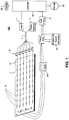
- Figure 1 depicts one non-limiting example non-limiting embodiment of a system (100) designed for the structural health monitoring (SHM) of an exemplary structure.
- (1) is a tunable laser connected to an optical circulator (2) provided with two outputs: a first output is connected to optical fibers (8) on which are connected a number of fiber Bragg gratings or sensors (9a, 9b, 9c); and a second output is connected to a photo detector (3).
- the photo detector (3) is in turn linked by any known means to a lock-in amplifier (4).
- the tunable laser (1) and the lock-in amplifier (4) are connected to a computer or other control processor 50.
- the lock-in amplifier (4) is also linked to a power amplifier (5) where is connected a number of actuators (6a, 6b, 6c).
- actuators (6a, 6b, 6c)
- the actuators (6) are linearly positioned in the boundary of the extremity of structural component (7).
- the FBG sensors (9) sense the amplitude and the phase of vibrational characteristics of structural component 7. These sensed amplitudes and phases encoded in laser light are selected by optical circulator 2, one light signal at a time, to photodetector 3. Photodetector 3 converts the received light signal to an analog electrical signal and provides the analog electrical signal to lock-In amplifier (4).
- Lock-in amplifier (4) comprises a conventional analog dual phase lock-in amplifier that measures the amplitude and phase of signals using a synchronous detection process to recover the signals. Lock-in amplifier (4) acts as a narrow-bandpass filter that removes unwanted noise while allowing through the signal that is to be measured.
- the frequency of the signal to be measured and thus the passband region of the filter is set by a reference signal, which is supplied by reference signal generator 52 to the lock-in amplifier along with the signal detected by the photodetector 3.
- the reference signal the reference signal generator 52 generates is at the same frequency as the modulation of the photodetector signal to be measured since the reference signal is also supplied to actuators 6.
- the lock-in amplifier (4) thus compares the frequency of the signal measured by photodetector (3) with the reference signals generated for the actuators (6). In this way the signals obtained by sensors (9) and the signals generated by the actuators (6) are synchronized. For each frequency of excitation, all the information generated by sensors (9) is stored in storage device 54 so as to be analyzed in order to evaluate the integrity of the structural component (7).
- the example non-limiting embodiment of system 100 comprises a set of at least two Bragg gratings 9 written along at least one optical fiber 10.
- the Bragg gratings 9 are attached (mechanically coupled) to the surface of the structural component 7 or embedded within the structural component, in the region where are defined to effect the monitoring, and provide strain measurements.
- a set of piezoelectric actuators 6 made up of at least one actuator are attached (mechanically coupled) to the surface of the structural component or embedded in its structure.
- a tunable laser 1 is used as a narrow band light source for the interrogation of the optical fiber sensors 9.
- the laser light source 1 sweeps a wide band of wave lengths so as to interrogate all the Bragg grating sensors 9 installed in the structural component 7 under monitoring.
- Different FBGs 9 can be written to reflect different light frequencies such that sweeping the laser light source across a band of light frequencies allows the system 100 to acquire strain characteristics sensed by disparately-located FBGs 9.
- the capability of an FBG 9 to measure strain is well known in the art.
- Optical circulator 2 is provided with two outputs: a first output sends the light signal emitted by the tunable laser 1 towards the Bragg grating sensors 9, and another output sends the signal reflected by the sensors back along the same optical fibers 10 to a photo detector 3.
- Lock-in amplifier 4 has a double function: (i) to use its own reference signal (from reference signal generator 52) to provide a harmonic signal for excitations of the piezoelectric actuators 6; and (ii) to recover the amplitude and phase of the senoidal (sinusoidal) strain signals, at this same frequency component, produced exclusively by the piezoelectric actuators 6 harmonically excited.
- Power amplifier 5 is designed to increase the excitation signal provided by the Lock-in amplifier reference signal generator 52.
- the piezoelectric actuators are fed by a continuous wave (CW) signal.
- a multiplexer 58 is used to control the distribution of the excitation harmonic signal (phase and amplitude) by the several piezoelectric actuators 6.
- Photo detector 3 is used to find the light signal reflected by the optical fiber sensors 9, turning it into an electrical signal conveyed to the lock-in amplifier 4.
- An optical fiber multiplexer 2 can be used in order to access more than one optical fiber in the case the sensors are distributed on more than one optical fiber 10.
- the system for the structural health monitoring (SHM) of a structural component a computer or other processing element 50 designed to (i) control the inspections by means of software, hardware, firmware or a combination thereof; and (ii) analyze the deformation signals so as to obtain the deformation field maps and compare them with the reference map, with detecting, locating and quantification of the damages in the structural component or the monitoring of the growth of some previously detected damage. That is, artificial intelligence-based software for pattern recognition performs automatically the comparison between deformation field's maps.
- FIG. 2 is a simplified flow-chart of a method according to the example non-limiting embodiment, which may be executed by processor 50 under control of software code stored in storage 54.
- (101) means the structural component is under monitoring.
- signal analysis is performed by means of frequency of excitation as described above.
- a deformation field map is generated at (103).
- the comparison between deformation field map generated with a deformation field map of reference or baseline is performed at (104).
- the damage detection (difference between the two maps) is evaluated by (105). In the absence of damage, the method returns to (101) and repeats steps (101) to (104). If any damage is detected, the method performs operations leading to the assessment of the Location of Damage at (106), followed by the assessment of the Severity of Damage at (107) and response with location and severity of damage at (108).
- An example non-limiting method for the structural health monitoring (SHM) of a structural component having at least an actuator and at least a sensor or a group of actuator and group of sensors may thus comprise:
- Figure 3 is a plot which represents the reflection spectrum of five FBG sensors, when irradiated with a wide band optical source.
- the photodetector 3 converts the reflection spectrum to an electrical signal that can be analyzed in the frequency domain. While it would be possible for controller 50 to provide a digital signal processor using FFT technology, the preferred non-limiting embodiment uses a simpler technique of a synchronous lock-in amplifier to synchronously detect the frequency and phase of the detected electrical signal.
- Figure 4 shows the example shift of the reflection spectrum of an example FBG sensor and variation of the amplitude in the inferred signal, when a mechanical excitation on the structure of interest is caused by a PZT actuator 6a. If the PZT actuator excitation is sinusoidal, the resulting FBG-detected signal will show a phase shift that changes sinusoidally. This phase shift can be synchronously detected by lock-in amplifier (4). These signals can be stored in storage 54 along with other signals stored for other frequencies and other sensors 6. The processor 50 executes a stored program to analyze the stored signals and generate a graphical deformation map for display on graphical display 56.
- Figure 5a illustrates an example 3D deformation map.
- the 3D map indicates a square delamination is at the center of the plate.
- the deformation map plots deformation ( ⁇ U.A.) against position (x, y).
- the deformation is represented by strain ⁇ -- which is defined as the amount of deformation per unit length of an object when a load is applied.
- the Fig. 5a deformation map further graphically shows the topography of strain, with lower strains having lower elevation and higher strains having higher elevations or peaks. Through such visualization, it is possible to see which parts of the structural element are under how much strain.
- the Figure 5b deformation map visualization is 2D and uses color encoding as described above to allow visualization of the amount of strain. Other representations are possible.
Landscapes
- Physics & Mathematics (AREA)
- General Physics & Mathematics (AREA)
- Chemical & Material Sciences (AREA)
- Pathology (AREA)
- Health & Medical Sciences (AREA)
- Analytical Chemistry (AREA)
- Biochemistry (AREA)
- General Health & Medical Sciences (AREA)
- Life Sciences & Earth Sciences (AREA)
- Immunology (AREA)
- Engineering & Computer Science (AREA)
- Aviation & Aerospace Engineering (AREA)
- Acoustics & Sound (AREA)
- Signal Processing (AREA)
- Length Measuring Devices By Optical Means (AREA)
- Investigating Or Analyzing Materials By The Use Of Ultrasonic Waves (AREA)
- Measurement Of Mechanical Vibrations Or Ultrasonic Waves (AREA)
- Optical Transform (AREA)
- Testing Of Devices, Machine Parts, Or Other Structures Thereof (AREA)
Claims (7)
- Procédé de surveillance de l'intégrité structurelle d'un élément structurel (7) présentant plusieurs capteurs (9) de réseau de Bragg sur fibre, FBG, répartis dans un réseau de capteurs de réseau FBG (10) fixés à la surface de l'élément structurel (7), le procédé comprenant l'étape ci-dessous consistant à :a) exciter l'élément structurel (7) en excitant au moins un actionneur (6) en utilisant des ondes continues à travers une gamme de fréquences prédéterminée, en vue de générer un champ de déformation dynamique dans l'élément structurel, le champ de déformation dynamique présentant des variations sinusoïdales temporisées aux mêmes fréquences qu'un signal d'excitation imposé sur ledit au moins un actionneur ;le procédé étant caractérisé par les étapes ci-dessous consistant à :b) mesurer un champ de déformation en utilisant la pluralité de capteurs de réseau FBG (9) répartis dans le réseau de capteurs de réseau FBG fixés à la surface de l'élément structurel, et notamment synchroniser l'actionnement dudit au moins un actionneur (6) avec une détection au moyen de la pluralité de capteurs de réseau FBG (9) en vue d'obtenir des mesures de contrainte ;c) filtrer les mesures du champ de déformation en vue de ne sélectionner que la partie du champ de déformation correspondant aux fréquences de l'actionnement sinusoïdal généré par ledit au moins un actionneur (6) ;d) en réponse, au moins en partie, à la mesure filtrée du champ de déformation, générer une carte de champ de déformation bidimensionnelle indiquant les amplitudes et les phases des contraintes de surface, ladite carte de champ de déformation étant basée sur l'amplitude et la phase mesurées par les multiples capteurs de réseau FBG (9) ;e) répéter la procédure pour de multiples fréquences d'excitation dudit au moins un actionneur (6) ;f) comparer les cartes de champ de déformation bidimensionnelles obtenues par les différentes fréquences d'excitation pour la détection de dommages structurels ; etg) mettre en œuvre une analyse informatique des cartes de champ de déformation bidimensionnelles ainsi obtenues, à l'aide de procédé de reconnaissance de formes, en vue d'identifier les dommages structurels.
- Procédé selon la revendication 1, dans lequel les capteurs de réseau FBG (9) détectent l'amplitude et la phase de caractéristiques vibratoires de l'élément structurel (7), dans lequel les amplitudes et les phases détectées sont codées en lumière laser et sont converties en signaux électriques ;
dans lequel un filtre passe-bande étroit est appliqué aux signaux électriques en vue d'éliminer tout bruit indésirable tout en permettant de mesurer un signal ;
dans lequel la région passe-bande du filtre est définie par un signal de référence à la même fréquence que les signaux générés pour exciter ledit au moins un actionneur (6). - Procédé selon la revendication 1, dans lequel ledit filtrage exclut non seulement l'amplitude mais aussi la phase, et sélectionne uniquement une fréquence spécifique du signal sinusoïdal utilisé dans l'alimentation dudit au moins un actionneur (6).
- Procédé selon la revendication 1, dans lequel le procédé inclut en outre l'étape consistant à obtenir une carte de champ de déformation bidimensionnelle de ligne de base en vue d'une comparaison lorsque l'élément structurel sous surveillance est exempt de défauts ou présente des défauts connus.
- Système destiné à surveiller l'intégrité structurelle d'un élément structurel (7) comprenant :un ordinateur configuré de manière à (i) commander des inspections en exécutant un logiciel ; et (ii) analyser des signaux de déformation en vue d'obtenir des cartes de champ de déformation et comparer les cartes de champ de déformation à une carte de référence, pour détecter, localiser et évaluer des dommages dans l'élément structurel (7) ou surveiller l'augmentation de certains dommages détectés précédemment ;un ensemble d'au moins deux réseaux de Bragg écrits le long d'au moins une fibre optique (10), les réseaux de Bragg formant des capteurs de réseau de Bragg (9), les capteurs de réseau de Bragg (9) étant positionnés longitudinalement sur ledit élément structurel (7) sous surveillance, les réseaux de Bragg étant fixés à une surface de l'élément structurel (7) et configurés de manière à effectuer une surveillance et à fournir des mesures de contrainte ;un ensemble d'actionneurs piézoélectriques (6) comprenant au moins un actionneur (6), fixé à la surface de l'élément structurel (7) ou intégré dans la structure de l'élément structurel (7) et alimenté par un signal d'onde continue ; caractérisé par :un laser accordable (1) utilisé en tant qu'une source de lumière à bande étroite pour interroger les capteurs de réseau de Bragg (9), le laser accordable (1) étant configuré de manière à balayer une large bande de longueurs d'onde afin d'interroger les capteurs de réseau de Bragg (9) installés dans l'élément structurel (7) sous surveillance ;un circulateur optique fournissant au moins des première et seconde sorties, la première sortie envoyant un signal lumineux émis par le laser accordable (1) vers les capteurs de réseau de Bragg (9), la seconde sortie envoyant le signal réfléchi par les capteurs de réseau de Bragg (9) vers un photodétecteur (3) ;un amplificateur de verrouillage (4) configuré de manière à mettre en œuvre une double fonction, à savoir : (i) utiliser son propre signal de référence pour fournir un signal harmonique pour les excitations de l'ensemble d'actionneurs piézoélectriques (6) ; et (ii) récupérer l'amplitude et la phase des signaux de contrainte sinusoïdaux, aux mêmes composantes de fréquence que le signal pour les excitations, produits par les actionneurs piézoélectriques excités de manière harmonique (6) ;un amplificateur de puissance (5) configuré de manière à augmenter le signal d'excitation fourni par l'amplificateur de verrouillage (4) ;un multiplexeur (58) configuré de manière à commander la répartition de la phase et de l'amplitude du signal harmonique d'excitation, par les actionneurs piézoélectriques (6) ;dans lequel le photodétecteur (3) est configuré de manière à détecter le signal lumineux réfléchi par les capteurs de réseau de Bragg (9), en transformant le signal lumineux détecté en un signal électrique et en acheminant le signal électrique vers l'amplificateur de verrouillage (4) ; etun multiplexeur de fibre optique (2) configuré de manière à accéder à plus d'une fibre optique dans le cas où les capteurs de réseau de Bragg (9) sont répartis sur plus d'une fibre optique.
- Système selon la revendication 5, dans lequel l'amplificateur de verrouillage (4) agit en tant qu'un filtre passe-bande étroit qui élimine tout bruit indésirable tout en permettant de mesurer les signaux de contrainte sinusoïdaux.
- Système selon la revendication 6, dans lequel la région passe-bande du filtre passe-bande étroit est définie par le signal de référence,
dans lequel le signal de référence est généré par un générateur de signal de référence (52) sur l'amplificateur de verrouillage, dans lequel le signal de référence est également fourni à l'ensemble d'actionneurs (6).
Applications Claiming Priority (2)
| Application Number | Priority Date | Filing Date | Title |
|---|---|---|---|
| US14/526,226 US10024756B2 (en) | 2014-10-28 | 2014-10-28 | Method and system for structural health monitoring with frequency synchronization |
| PCT/BR2015/000163 WO2016065446A1 (fr) | 2014-10-28 | 2015-10-21 | Procédé et système pour la surveillance de l'intégrité des structures avec une synchronisation de fréquence |
Publications (2)
| Publication Number | Publication Date |
|---|---|
| EP3213045A1 EP3213045A1 (fr) | 2017-09-06 |
| EP3213045B1 true EP3213045B1 (fr) | 2020-05-27 |
Family
ID=54754396
Family Applications (1)
| Application Number | Title | Priority Date | Filing Date |
|---|---|---|---|
| EP15801985.1A Active EP3213045B1 (fr) | 2014-10-28 | 2015-10-21 | Procédé et système pour la surveillance de l'intégrité des structures avec une synchronisation de fréquence |
Country Status (5)
| Country | Link |
|---|---|
| US (1) | US10024756B2 (fr) |
| EP (1) | EP3213045B1 (fr) |
| CN (1) | CN107438758B (fr) |
| BR (1) | BR112017008942B1 (fr) |
| WO (1) | WO2016065446A1 (fr) |
Families Citing this family (32)
| Publication number | Priority date | Publication date | Assignee | Title |
|---|---|---|---|---|
| US20160317050A1 (en) | 2015-04-28 | 2016-11-03 | Federico Perego Costa | Hemodynamic parameter (Hdp) monitoring system for diagnosis of a health condition of a patient |
| US10018569B2 (en) | 2016-05-12 | 2018-07-10 | Northrop Grumman Systems Corporation | Optical fiber communications with composite structural monitoring for determining damaged structure based on the analysis of optical signal |
| US11029231B2 (en) * | 2016-10-25 | 2021-06-08 | Nec Corporation | Assessing device, assessing system, assessing method, and computer-readable recording medium |
| WO2018112413A1 (fr) * | 2016-12-15 | 2018-06-21 | Costa Frederico Perego | Système destiné à la caractérisation, au diagnostic et au traitement d'un état de santé d'un patient et procédés d'utilisation dudit système |
| CN110573874B (zh) * | 2017-04-28 | 2023-03-14 | 三美电机株式会社 | 检测系统和检测方法 |
| US10401316B2 (en) * | 2017-05-23 | 2019-09-03 | Simmonds Precision Products, Inc. | Acoustic event monitoring for triggering of health scan of a structure |
| US10495610B2 (en) * | 2017-08-14 | 2019-12-03 | Geoffrey A. Cranch | Fiber optic acoustic emission sensor and apparatus |
| US11073465B2 (en) * | 2017-08-21 | 2021-07-27 | The Board Of Trustees Of The University Of Illinois | Real-time sensing of flowing nanoparticles with electro-opto-mechanics |
| DE102018103452A1 (de) * | 2018-02-15 | 2019-08-22 | Airbus Defence and Space GmbH | Verfahren zur Implementierung und Anbindung strukturintegrierter Lichtwellenleiter |
| JP2019184389A (ja) * | 2018-04-09 | 2019-10-24 | 株式会社Subaru | 診断装置 |
| EP3561473A1 (fr) * | 2018-04-25 | 2019-10-30 | Airbus Operations, S.L. | Structure composite avec fonction de localisation de dommages et procédé de fabrication d'une structure composite avec fonction de localisation de dommages |
| ES2961917T3 (es) * | 2018-06-28 | 2024-03-14 | Synaptec Ltd | Métodos y aparatos para realizar una medición fasorial sincronizada en el tiempo |
| US10816436B2 (en) * | 2018-07-06 | 2020-10-27 | The Boeing Company | System for temperature insensitive damage detection |
| DE102018221016A1 (de) * | 2018-12-05 | 2020-06-10 | Robert Bosch Gmbh | Verfahren zur Prüfung eines Faserverbundbauteils, Vorrichtung, Computerprogramm und maschinenlesbares Speichermedium |
| CN109752383B (zh) * | 2018-12-28 | 2021-02-26 | 东南大学 | 一种基于多重交叉验证的桥梁损伤识别方法 |
| CN109458924B (zh) * | 2018-12-29 | 2023-04-07 | 山东大学 | 基于十轴传感器的阻值机敏格栅变形测试系统及方法 |
| US11464440B2 (en) | 2019-04-10 | 2022-10-11 | Autem Medical, Llc | System for prognosticating patient outcomes and methods of using the same |
| RU2747160C2 (ru) * | 2019-07-19 | 2021-04-28 | Ооо "Содис Лаб" | Система выявления и контроля зон изменения напряженно-деформированного состояния строительных конструкций |
| CN110658261A (zh) * | 2019-10-10 | 2020-01-07 | 天津科技大学 | 一种基于超声导波的结构健康监测选频方法 |
| US11543286B2 (en) * | 2020-04-14 | 2023-01-03 | Nec Corporation | Distributed acoustic sensing based acoustic wave speed scanning and mapping of civil infrastructures |
| CN112394107A (zh) * | 2020-09-16 | 2021-02-23 | 昆明理工大学 | 一种基于ZigBee无线传感网络与压电传感器的结构健康监测系统及方法 |
| JP7675525B2 (ja) * | 2021-01-29 | 2025-05-13 | 東京エレクトロン株式会社 | 測定用治具 |
| EP4050313A1 (fr) * | 2021-02-25 | 2022-08-31 | Universitat Politècnica De Catalunya | Système et procédé de mesure de réponse de structures |
| US12352618B2 (en) | 2021-04-12 | 2025-07-08 | Board Of Trustees Of Michigan State University | Demodulation of fiber optic sensors |
| CN113639844B (zh) * | 2021-07-14 | 2024-05-03 | 安徽复盛信息科技有限公司 | 基于光栅测温的污水处理厂曝气设备健康情况监测方法 |
| CN113945633B (zh) * | 2021-09-30 | 2022-10-28 | 西安交通大学 | 一种基于高空间分辨率振型分型维数的结构微弱损伤识别方法 |
| CN113959354B (zh) * | 2021-11-26 | 2022-10-11 | 中国铁道科学研究院集团有限公司 | 一种基于光纤传感的结构变形测量装置及方法 |
| TWI788182B (zh) * | 2022-01-07 | 2022-12-21 | 盛遠實業有限公司 | 分佈連續式高精度雙向變位光纖量測系統及其量測方法 |
| US12264983B2 (en) * | 2022-05-31 | 2025-04-01 | Simmonds Precision Products, Inc. | Bracelet sensing array |
| CN115420799B (zh) * | 2022-09-01 | 2025-06-24 | 江西师范大学 | 基于结构振动-光纤声导波传感的无损检测方法 |
| CN120027999B (zh) * | 2025-04-23 | 2025-07-01 | 山西省安装集团股份有限公司 | 一种基于振动分析的支撑架监测系统 |
| CN120255011B (zh) * | 2025-06-03 | 2025-08-01 | 南通理工学院 | 一种接地网腐蚀分析预测系统 |
Citations (1)
| Publication number | Priority date | Publication date | Assignee | Title |
|---|---|---|---|---|
| US20100312493A1 (en) * | 2009-04-29 | 2010-12-09 | Purekar Ashish S | Corrosion inspection and monitoring system |
Family Cites Families (22)
| Publication number | Priority date | Publication date | Assignee | Title |
|---|---|---|---|---|
| US5184516A (en) | 1991-07-31 | 1993-02-09 | Hughes Aircraft Company | Conformal circuit for structural health monitoring and assessment |
| US5814729A (en) | 1996-09-09 | 1998-09-29 | Mcdonnell Douglas Corporation | System for in-situ delamination detection in composites |
| US6006163A (en) * | 1997-09-15 | 1999-12-21 | Mcdonnell Douglas Corporation | Active damage interrogation method for structural health monitoring |
| US6370964B1 (en) | 1998-11-23 | 2002-04-16 | The Board Of Trustees Of The Leland Stanford Junior University | Diagnostic layer and methods for detecting structural integrity of composite and metallic materials |
| US6233085B1 (en) * | 1999-10-19 | 2001-05-15 | The Boeing Company | Apparatus, method, and computer program product for controlling an interferromic phased array |
| US6399939B1 (en) | 2000-06-13 | 2002-06-04 | North Carolina A&T State University | Sensor array system |
| US20030167141A1 (en) | 2001-12-20 | 2003-09-04 | Staszewski Wieslaw J. | Structural health monitoring |
| DE10214984B4 (de) | 2002-04-04 | 2006-01-19 | Eads Deutschland Gmbh | Aktorik- und Sensoriksystem für Verbundstrukturen |
| US7325456B2 (en) * | 2003-09-22 | 2008-02-05 | Hyeung-Yun Kim | Interrogation network patches for active monitoring of structural health conditions |
| US7536911B2 (en) | 2003-09-22 | 2009-05-26 | Hyeung-Yun Kim | Diagnostic systems of optical fiber coil sensors for structural health monitoring |
| AU2004277166A1 (en) * | 2003-09-22 | 2005-04-07 | Kim Hyeung-Yun | Sensors and systems for structural health monitoring |
| US7426447B2 (en) | 2005-08-09 | 2008-09-16 | The Boeing Company | Method and system for monitoring structural damage |
| US7930128B2 (en) | 2007-04-16 | 2011-04-19 | Acellent Technologies, Inc. | Robust damage detection |
| US20080291456A1 (en) * | 2007-05-24 | 2008-11-27 | Ghislain Lucien P | Sensor apparatus and method using optical interferometry |
| JP5224547B2 (ja) * | 2008-02-13 | 2013-07-03 | 国立大学法人京都工芸繊維大学 | 構造物の損傷の診断方法および装置 |
| US8386118B2 (en) * | 2009-08-04 | 2013-02-26 | The Boeing Company | System and method for detecting an anomaly in a hidden layer of a multi-layer structure |
| CA2816700A1 (fr) * | 2010-11-01 | 2012-05-10 | Ray Bond | Identification de charge d'impact sur la base de l'entropie |
| EP2485026B1 (fr) | 2011-02-08 | 2019-05-01 | The Boeing Company | Système de surveillance de la santé structurelle |
| CN102419348B (zh) * | 2011-08-19 | 2013-05-08 | 北京航空航天大学 | 一种基于光纤布拉格光栅的声发射信号功率型无损检测方法 |
| US9158054B2 (en) * | 2011-11-02 | 2015-10-13 | University Of South Carolina | Acousto-ultrasonic sensor |
| CN103575664B (zh) * | 2013-10-08 | 2017-06-20 | 南京航空航天大学 | 基于集成式复合传感器的结构多尺度健康监测装置与方法 |
| CN104006900A (zh) * | 2014-06-12 | 2014-08-27 | 东华大学 | 一种多功能型结构健康和边界安防光纤监测系统 |
-
2014
- 2014-10-28 US US14/526,226 patent/US10024756B2/en active Active
-
2015
- 2015-10-21 BR BR112017008942-4A patent/BR112017008942B1/pt active IP Right Grant
- 2015-10-21 CN CN201580064155.4A patent/CN107438758B/zh active Active
- 2015-10-21 EP EP15801985.1A patent/EP3213045B1/fr active Active
- 2015-10-21 WO PCT/BR2015/000163 patent/WO2016065446A1/fr not_active Ceased
Patent Citations (1)
| Publication number | Priority date | Publication date | Assignee | Title |
|---|---|---|---|---|
| US20100312493A1 (en) * | 2009-04-29 | 2010-12-09 | Purekar Ashish S | Corrosion inspection and monitoring system |
Also Published As
| Publication number | Publication date |
|---|---|
| WO2016065446A1 (fr) | 2016-05-06 |
| US20160116366A1 (en) | 2016-04-28 |
| EP3213045A1 (fr) | 2017-09-06 |
| CN107438758B (zh) | 2020-10-09 |
| BR112017008942B1 (pt) | 2021-03-02 |
| BR112017008942A2 (pt) | 2018-01-02 |
| US10024756B2 (en) | 2018-07-17 |
| CN107438758A (zh) | 2017-12-05 |
Similar Documents
| Publication | Publication Date | Title |
|---|---|---|
| US10024756B2 (en) | Method and system for structural health monitoring with frequency synchronization | |
| Gomes et al. | The use of intelligent computational tools for damage detection and identification with an emphasis on composites–A review | |
| US10724994B2 (en) | Structural health monitoring method and system | |
| US6370964B1 (en) | Diagnostic layer and methods for detecting structural integrity of composite and metallic materials | |
| Park et al. | PZT-based active damage detection techniques for steel bridge components | |
| Güemes | SHM technologies and applications in aircraft structures | |
| Doliński et al. | Detection of Delamination in Laminate Wind Turbine Blades Using One‐Dimensional Wavelet Analysis of Modal Responses | |
| Demetgul et al. | Evaluation of the health of riveted joints with active and passive structural health monitoring techniques | |
| Memmolo et al. | Model assisted probability of detection for a guided waves based SHM technique | |
| AU2004277167A1 (en) | Methods for monitoring structural health conditions | |
| Ciminello et al. | Stringer debonding edge detection employing fiber optics by combined distributed strain profile and wave scattering approaches for non-model based SHM | |
| JP7429410B2 (ja) | 光ファイバセンシングシステム、損傷監視方法、及び損傷箇所画像化方法 | |
| Memmolo et al. | Experimental characterization of a composite structures health monitoring methodology | |
| Ciminello et al. | Impact area and debonding line detection assessment by cross-correlation analysis and distributed sensing | |
| Malinowski et al. | Damage detection potential of a triangular piezoelectric configuration | |
| Park et al. | Damage diagnostics on a welded zone of a steel truss member using an active sensing network system | |
| Haider et al. | Sensors, Sensor Network, and SHM | |
| Moslehi et al. | Multifunctional fiber Bragg grating sensing system for load monitoring of composite wings | |
| Kurnyta et al. | Assessment of sensor technologies for aircraft SHM systems | |
| Faisal Haider et al. | Sensors, Sensor Network, and SHM | |
| Park et al. | Instantaneous damage identification and localization through sparse laser ultrasonic scanning | |
| SOMAN et al. | Fiber Bragg Grating Sensor Based Mode Filtering Using Cosine Distance Metric | |
| Medeiros et al. | Debonding identification in metalcomposite bonded joint using vibration testing | |
| Park et al. | Active sensing network system for crack detection on welded zone of steel truss member | |
| Banerjee et al. | Structural Health Monitoring of Composite Structures: Utility, Challenges, Sensor Technologies, and Advanced Methods |
Legal Events
| Date | Code | Title | Description |
|---|---|---|---|
| STAA | Information on the status of an ep patent application or granted ep patent |
Free format text: STATUS: THE INTERNATIONAL PUBLICATION HAS BEEN MADE |
|
| PUAI | Public reference made under article 153(3) epc to a published international application that has entered the european phase |
Free format text: ORIGINAL CODE: 0009012 |
|
| STAA | Information on the status of an ep patent application or granted ep patent |
Free format text: STATUS: REQUEST FOR EXAMINATION WAS MADE |
|
| 17P | Request for examination filed |
Effective date: 20170427 |
|
| AK | Designated contracting states |
Kind code of ref document: A1 Designated state(s): AL AT BE BG CH CY CZ DE DK EE ES FI FR GB GR HR HU IE IS IT LI LT LU LV MC MK MT NL NO PL PT RO RS SE SI SK SM TR |
|
| AX | Request for extension of the european patent |
Extension state: BA ME |
|
| DAV | Request for validation of the european patent (deleted) | ||
| DAX | Request for extension of the european patent (deleted) | ||
| STAA | Information on the status of an ep patent application or granted ep patent |
Free format text: STATUS: EXAMINATION IS IN PROGRESS |
|
| 17Q | First examination report despatched |
Effective date: 20180925 |
|
| GRAP | Despatch of communication of intention to grant a patent |
Free format text: ORIGINAL CODE: EPIDOSNIGR1 |
|
| STAA | Information on the status of an ep patent application or granted ep patent |
Free format text: STATUS: GRANT OF PATENT IS INTENDED |
|
| RIC1 | Information provided on ipc code assigned before grant |
Ipc: G01M 5/00 20060101AFI20191118BHEP Ipc: G01N 29/11 20060101ALI20191118BHEP Ipc: G01N 29/44 20060101ALI20191118BHEP Ipc: G01N 29/34 20060101ALI20191118BHEP |
|
| INTG | Intention to grant announced |
Effective date: 20191205 |
|
| GRAS | Grant fee paid |
Free format text: ORIGINAL CODE: EPIDOSNIGR3 |
|
| GRAA | (expected) grant |
Free format text: ORIGINAL CODE: 0009210 |
|
| STAA | Information on the status of an ep patent application or granted ep patent |
Free format text: STATUS: THE PATENT HAS BEEN GRANTED |
|
| RAP1 | Party data changed (applicant data changed or rights of an application transferred) |
Owner name: FACULDADES CATOLICAS, SOCIEDADE CIVIL MANTENEDORA Owner name: EMBRAER S.A. |
|
| AK | Designated contracting states |
Kind code of ref document: B1 Designated state(s): AL AT BE BG CH CY CZ DE DK EE ES FI FR GB GR HR HU IE IS IT LI LT LU LV MC MK MT NL NO PL PT RO RS SE SI SK SM TR |
|
| REG | Reference to a national code |
Ref country code: GB Ref legal event code: FG4D |
|
| REG | Reference to a national code |
Ref country code: CH Ref legal event code: EP |
|
| REG | Reference to a national code |
Ref country code: AT Ref legal event code: REF Ref document number: 1275033 Country of ref document: AT Kind code of ref document: T Effective date: 20200615 |
|
| REG | Reference to a national code |
Ref country code: DE Ref legal event code: R096 Ref document number: 602015053456 Country of ref document: DE |
|
| REG | Reference to a national code |
Ref country code: LT Ref legal event code: MG4D |
|
| PG25 | Lapsed in a contracting state [announced via postgrant information from national office to epo] |
Ref country code: GR Free format text: LAPSE BECAUSE OF FAILURE TO SUBMIT A TRANSLATION OF THE DESCRIPTION OR TO PAY THE FEE WITHIN THE PRESCRIBED TIME-LIMIT Effective date: 20200828 Ref country code: FI Free format text: LAPSE BECAUSE OF FAILURE TO SUBMIT A TRANSLATION OF THE DESCRIPTION OR TO PAY THE FEE WITHIN THE PRESCRIBED TIME-LIMIT Effective date: 20200527 Ref country code: PT Free format text: LAPSE BECAUSE OF FAILURE TO SUBMIT A TRANSLATION OF THE DESCRIPTION OR TO PAY THE FEE WITHIN THE PRESCRIBED TIME-LIMIT Effective date: 20200928 Ref country code: SE Free format text: LAPSE BECAUSE OF FAILURE TO SUBMIT A TRANSLATION OF THE DESCRIPTION OR TO PAY THE FEE WITHIN THE PRESCRIBED TIME-LIMIT Effective date: 20200527 Ref country code: NO Free format text: LAPSE BECAUSE OF FAILURE TO SUBMIT A TRANSLATION OF THE DESCRIPTION OR TO PAY THE FEE WITHIN THE PRESCRIBED TIME-LIMIT Effective date: 20200827 Ref country code: IS Free format text: LAPSE BECAUSE OF FAILURE TO SUBMIT A TRANSLATION OF THE DESCRIPTION OR TO PAY THE FEE WITHIN THE PRESCRIBED TIME-LIMIT Effective date: 20200927 Ref country code: LT Free format text: LAPSE BECAUSE OF FAILURE TO SUBMIT A TRANSLATION OF THE DESCRIPTION OR TO PAY THE FEE WITHIN THE PRESCRIBED TIME-LIMIT Effective date: 20200527 |
|
| REG | Reference to a national code |
Ref country code: NL Ref legal event code: MP Effective date: 20200527 |
|
| PG25 | Lapsed in a contracting state [announced via postgrant information from national office to epo] |
Ref country code: BG Free format text: LAPSE BECAUSE OF FAILURE TO SUBMIT A TRANSLATION OF THE DESCRIPTION OR TO PAY THE FEE WITHIN THE PRESCRIBED TIME-LIMIT Effective date: 20200827 Ref country code: RS Free format text: LAPSE BECAUSE OF FAILURE TO SUBMIT A TRANSLATION OF THE DESCRIPTION OR TO PAY THE FEE WITHIN THE PRESCRIBED TIME-LIMIT Effective date: 20200527 Ref country code: HR Free format text: LAPSE BECAUSE OF FAILURE TO SUBMIT A TRANSLATION OF THE DESCRIPTION OR TO PAY THE FEE WITHIN THE PRESCRIBED TIME-LIMIT Effective date: 20200527 Ref country code: LV Free format text: LAPSE BECAUSE OF FAILURE TO SUBMIT A TRANSLATION OF THE DESCRIPTION OR TO PAY THE FEE WITHIN THE PRESCRIBED TIME-LIMIT Effective date: 20200527 |
|
| REG | Reference to a national code |
Ref country code: AT Ref legal event code: MK05 Ref document number: 1275033 Country of ref document: AT Kind code of ref document: T Effective date: 20200527 |
|
| PG25 | Lapsed in a contracting state [announced via postgrant information from national office to epo] |
Ref country code: NL Free format text: LAPSE BECAUSE OF FAILURE TO SUBMIT A TRANSLATION OF THE DESCRIPTION OR TO PAY THE FEE WITHIN THE PRESCRIBED TIME-LIMIT Effective date: 20200527 Ref country code: AL Free format text: LAPSE BECAUSE OF FAILURE TO SUBMIT A TRANSLATION OF THE DESCRIPTION OR TO PAY THE FEE WITHIN THE PRESCRIBED TIME-LIMIT Effective date: 20200527 |
|
| PG25 | Lapsed in a contracting state [announced via postgrant information from national office to epo] |
Ref country code: ES Free format text: LAPSE BECAUSE OF FAILURE TO SUBMIT A TRANSLATION OF THE DESCRIPTION OR TO PAY THE FEE WITHIN THE PRESCRIBED TIME-LIMIT Effective date: 20200527 Ref country code: AT Free format text: LAPSE BECAUSE OF FAILURE TO SUBMIT A TRANSLATION OF THE DESCRIPTION OR TO PAY THE FEE WITHIN THE PRESCRIBED TIME-LIMIT Effective date: 20200527 Ref country code: DK Free format text: LAPSE BECAUSE OF FAILURE TO SUBMIT A TRANSLATION OF THE DESCRIPTION OR TO PAY THE FEE WITHIN THE PRESCRIBED TIME-LIMIT Effective date: 20200527 Ref country code: EE Free format text: LAPSE BECAUSE OF FAILURE TO SUBMIT A TRANSLATION OF THE DESCRIPTION OR TO PAY THE FEE WITHIN THE PRESCRIBED TIME-LIMIT Effective date: 20200527 Ref country code: SM Free format text: LAPSE BECAUSE OF FAILURE TO SUBMIT A TRANSLATION OF THE DESCRIPTION OR TO PAY THE FEE WITHIN THE PRESCRIBED TIME-LIMIT Effective date: 20200527 Ref country code: IT Free format text: LAPSE BECAUSE OF FAILURE TO SUBMIT A TRANSLATION OF THE DESCRIPTION OR TO PAY THE FEE WITHIN THE PRESCRIBED TIME-LIMIT Effective date: 20200527 Ref country code: RO Free format text: LAPSE BECAUSE OF FAILURE TO SUBMIT A TRANSLATION OF THE DESCRIPTION OR TO PAY THE FEE WITHIN THE PRESCRIBED TIME-LIMIT Effective date: 20200527 Ref country code: CZ Free format text: LAPSE BECAUSE OF FAILURE TO SUBMIT A TRANSLATION OF THE DESCRIPTION OR TO PAY THE FEE WITHIN THE PRESCRIBED TIME-LIMIT Effective date: 20200527 |
|
| PG25 | Lapsed in a contracting state [announced via postgrant information from national office to epo] |
Ref country code: PL Free format text: LAPSE BECAUSE OF FAILURE TO SUBMIT A TRANSLATION OF THE DESCRIPTION OR TO PAY THE FEE WITHIN THE PRESCRIBED TIME-LIMIT Effective date: 20200527 Ref country code: SK Free format text: LAPSE BECAUSE OF FAILURE TO SUBMIT A TRANSLATION OF THE DESCRIPTION OR TO PAY THE FEE WITHIN THE PRESCRIBED TIME-LIMIT Effective date: 20200527 |
|
| REG | Reference to a national code |
Ref country code: DE Ref legal event code: R097 Ref document number: 602015053456 Country of ref document: DE |
|
| PLBE | No opposition filed within time limit |
Free format text: ORIGINAL CODE: 0009261 |
|
| STAA | Information on the status of an ep patent application or granted ep patent |
Free format text: STATUS: NO OPPOSITION FILED WITHIN TIME LIMIT |
|
| REG | Reference to a national code |
Ref country code: DE Ref legal event code: R119 Ref document number: 602015053456 Country of ref document: DE |
|
| 26N | No opposition filed |
Effective date: 20210302 |
|
| PG25 | Lapsed in a contracting state [announced via postgrant information from national office to epo] |
Ref country code: SI Free format text: LAPSE BECAUSE OF FAILURE TO SUBMIT A TRANSLATION OF THE DESCRIPTION OR TO PAY THE FEE WITHIN THE PRESCRIBED TIME-LIMIT Effective date: 20200527 |
|
| REG | Reference to a national code |
Ref country code: CH Ref legal event code: PL |
|
| GBPC | Gb: european patent ceased through non-payment of renewal fee |
Effective date: 20201021 |
|
| PG25 | Lapsed in a contracting state [announced via postgrant information from national office to epo] |
Ref country code: MC Free format text: LAPSE BECAUSE OF FAILURE TO SUBMIT A TRANSLATION OF THE DESCRIPTION OR TO PAY THE FEE WITHIN THE PRESCRIBED TIME-LIMIT Effective date: 20200527 Ref country code: LU Free format text: LAPSE BECAUSE OF NON-PAYMENT OF DUE FEES Effective date: 20201021 |
|
| REG | Reference to a national code |
Ref country code: BE Ref legal event code: MM Effective date: 20201031 |
|
| PG25 | Lapsed in a contracting state [announced via postgrant information from national office to epo] |
Ref country code: DE Free format text: LAPSE BECAUSE OF NON-PAYMENT OF DUE FEES Effective date: 20210501 |
|
| PG25 | Lapsed in a contracting state [announced via postgrant information from national office to epo] |
Ref country code: LI Free format text: LAPSE BECAUSE OF NON-PAYMENT OF DUE FEES Effective date: 20201031 Ref country code: GB Free format text: LAPSE BECAUSE OF NON-PAYMENT OF DUE FEES Effective date: 20201021 Ref country code: CH Free format text: LAPSE BECAUSE OF NON-PAYMENT OF DUE FEES Effective date: 20201031 Ref country code: BE Free format text: LAPSE BECAUSE OF NON-PAYMENT OF DUE FEES Effective date: 20201031 |
|
| PG25 | Lapsed in a contracting state [announced via postgrant information from national office to epo] |
Ref country code: IE Free format text: LAPSE BECAUSE OF NON-PAYMENT OF DUE FEES Effective date: 20201021 |
|
| PG25 | Lapsed in a contracting state [announced via postgrant information from national office to epo] |
Ref country code: TR Free format text: LAPSE BECAUSE OF FAILURE TO SUBMIT A TRANSLATION OF THE DESCRIPTION OR TO PAY THE FEE WITHIN THE PRESCRIBED TIME-LIMIT Effective date: 20200527 Ref country code: MT Free format text: LAPSE BECAUSE OF FAILURE TO SUBMIT A TRANSLATION OF THE DESCRIPTION OR TO PAY THE FEE WITHIN THE PRESCRIBED TIME-LIMIT Effective date: 20200527 Ref country code: CY Free format text: LAPSE BECAUSE OF FAILURE TO SUBMIT A TRANSLATION OF THE DESCRIPTION OR TO PAY THE FEE WITHIN THE PRESCRIBED TIME-LIMIT Effective date: 20200527 |
|
| PG25 | Lapsed in a contracting state [announced via postgrant information from national office to epo] |
Ref country code: MK Free format text: LAPSE BECAUSE OF FAILURE TO SUBMIT A TRANSLATION OF THE DESCRIPTION OR TO PAY THE FEE WITHIN THE PRESCRIBED TIME-LIMIT Effective date: 20200527 |
|
| PGFP | Annual fee paid to national office [announced via postgrant information from national office to epo] |
Ref country code: FR Payment date: 20251027 Year of fee payment: 11 |