EP3212868B1 - Gravity locking mechanism - Google Patents
Gravity locking mechanism Download PDFInfo
- Publication number
- EP3212868B1 EP3212868B1 EP15853874.4A EP15853874A EP3212868B1 EP 3212868 B1 EP3212868 B1 EP 3212868B1 EP 15853874 A EP15853874 A EP 15853874A EP 3212868 B1 EP3212868 B1 EP 3212868B1
- Authority
- EP
- European Patent Office
- Prior art keywords
- locking
- article
- gravity load
- locking mechanism
- load
- Prior art date
- Legal status (The legal status is an assumption and is not a legal conclusion. Google has not performed a legal analysis and makes no representation as to the accuracy of the status listed.)
- Active
Links
- 230000005484 gravity Effects 0.000 title claims description 128
- 230000007246 mechanism Effects 0.000 title claims description 101
- 230000000295 complement effect Effects 0.000 claims description 6
- 230000009471 action Effects 0.000 description 2
- 238000009434 installation Methods 0.000 description 2
- 239000000463 material Substances 0.000 description 2
- 230000027455 binding Effects 0.000 description 1
- 238000009739 binding Methods 0.000 description 1
- 230000008859 change Effects 0.000 description 1
- 230000008878 coupling Effects 0.000 description 1
- 238000010168 coupling process Methods 0.000 description 1
- 238000005859 coupling reaction Methods 0.000 description 1
- 238000005516 engineering process Methods 0.000 description 1
- 238000000034 method Methods 0.000 description 1
- 230000001737 promoting effect Effects 0.000 description 1
- 230000004044 response Effects 0.000 description 1
- 238000005096 rolling process Methods 0.000 description 1
- 239000007787 solid Substances 0.000 description 1
- 239000002699 waste material Substances 0.000 description 1
Images


Classifications
-
- B—PERFORMING OPERATIONS; TRANSPORTING
- B25—HAND TOOLS; PORTABLE POWER-DRIVEN TOOLS; MANIPULATORS
- B25H—WORKSHOP EQUIPMENT, e.g. FOR MARKING-OUT WORK; STORAGE MEANS FOR WORKSHOPS
- B25H1/00—Work benches; Portable stands or supports for positioning portable tools or work to be operated on thereby
- B25H1/08—Work benches; Portable stands or supports for positioning portable tools or work to be operated on thereby with provision for attachment of work holders
-
- B—PERFORMING OPERATIONS; TRANSPORTING
- B25—HAND TOOLS; PORTABLE POWER-DRIVEN TOOLS; MANIPULATORS
- B25H—WORKSHOP EQUIPMENT, e.g. FOR MARKING-OUT WORK; STORAGE MEANS FOR WORKSHOPS
- B25H1/00—Work benches; Portable stands or supports for positioning portable tools or work to be operated on thereby
- B25H1/0021—Stands, supports or guiding devices for positioning portable tools or for securing them to the work
- B25H1/0057—Devices for securing hand tools to the work
- B25H1/0064—Stands attached to the workpiece
-
- F—MECHANICAL ENGINEERING; LIGHTING; HEATING; WEAPONS; BLASTING
- F16—ENGINEERING ELEMENTS AND UNITS; GENERAL MEASURES FOR PRODUCING AND MAINTAINING EFFECTIVE FUNCTIONING OF MACHINES OR INSTALLATIONS; THERMAL INSULATION IN GENERAL
- F16M—FRAMES, CASINGS OR BEDS OF ENGINES, MACHINES OR APPARATUS, NOT SPECIFIC TO ENGINES, MACHINES OR APPARATUS PROVIDED FOR ELSEWHERE; STANDS; SUPPORTS
- F16M11/00—Stands or trestles as supports for apparatus or articles placed thereon Stands for scientific apparatus such as gravitational force meters
- F16M11/02—Heads
- F16M11/04—Means for attachment of apparatus; Means allowing adjustment of the apparatus relatively to the stand
- F16M11/041—Allowing quick release of the apparatus
Definitions
- This disclosure relates generally to locking mechanisms, and, more particularly, to gravity or weight actuated locking mechanisms, in particular for mounting systems configured to mount power tools onto a work surface.
- Locking mechanisms of various types have long been used for a wide variety of applications.
- a locking mechanism generally has two states, a locked state, whereby the locking mechanism restrains an article, and an un-locked state, whereby the article is not restrained.
- An actuation member is generally is operable to switch the locking mechanism between the locked and un-locked states.
- Different types of locking mechanisms and actuation members may be optimal for different types of applications. For instance, it may be desirable for a locking mechanism to self-engage and automatically switch between the un-locked state and the locked state under certain circumstances, such as the position or orientation of the article, for example.
- U.S. Pat. No. 5,123,664 describes a locking mechanism for removably coupling an ice skate runner to a skate shoe without manual manipulation of the locking mechanism.
- a definition or use of a term in a reference is inconsistent or contrary to the definition of that term provided herein, the definition of that term provided herein applies to this disclosure and the definition of that term in the reference does not apply to this disclosure.
- a user positions a slot of the runner over a pin on the skate shoe.
- Stepping into the skate shoe pushes a locking end of the runner into a snap-locking mechanism on the shoe, and the user's weight causes the snap-locking mechanism to engage and lock the locking end of the runner in place.
- the user manually engages a release that disengages the snap-locking mechanism.
- hooks that release at a certain orientation, or moving elements that are brought into an actuation position by gravity when in a certain orientation, such as, for example, the rolling sphere in the gravity locking articulation of a briefcase that unlocks when the briefcase is properly oriented, as described in U.S. Pat. No. 5,369,843 .
- Some locking mechanisms such as ski bindings, are designed to automatically release under extreme forces such as those experienced in a ski crash.
- a mounting system to mount an article such as a power tool like a miter saw onto a workspace.
- Such mounting system desirably restrains both the location and orientation of the power tool on the workspace, as movement or rotation may damage a workpiece or the tool, or injure a user.
- Such systems also desirably provide for easy installation and removal of the tool from the mounting system.
- US 2006/0076756 A1 discloses a table saw cart comprised of a framework of a carrier containing multiple lateral and longitudinal frames.
- US 6,666,485 B1 discloses a locking/unlocking device for a waste collection container for automatically locking/unlocking, by gravity.
- a locking mechanism In order to facilitate locking and unlocking an article to and from a mounting system, respectively, without manual actuation of an actuation member, a locking mechanism according to this disclosure is configured so as to be actuated by weight of the article. In other words, the weight of the article actuates the locking mechanism to switch from an unlocked state to a locked state. Additionally, the locking mechanism is disengaged, i.e., switched from the locked state to the unlocked state, when the weight of the article is removed.
- the mounting structure is rigidly supported on a surface, such as a workbench, wall, or the like, and defines a first alignment surface, a first locking surface, and a first load surface.
- a surface such as a workbench, wall, or the like
- An article to be locked in terms of orientation and position on the surface includes an alignment structure, a gravity load structure, and a locking structure.
- the alignment structure is fixed to the article, and defines a second alignment surface that, once engaged with the first alignment surface, aligns the article with the mounting structure.
- the gravity load structure is movable on the article, is biased toward an unrestrained position, and defines a second load surface facing toward the mounting structure. As the article moves toward the mounting structure, the second load surface comes into contact with and bears against the first load surface to move the gravity load structure away from the unrestrained position.
- the locking structure is movably attached to the article, and configured such that a movement of the gravity load structure away from and toward the unrestrained position corresponds with a movement of the locking structure toward and away from a closed position respectively.
- the locking structure defines a second locking surface that engages the first locking surface in the closed position to delimit the corresponding movement of the locking structure and the gravity load structure such that as at least a portion of a weight of the article is supported on the first load surface via the second load surface, the second locking surface is urged against the first locking surface to hold the mounting structure captive between the locking structure and the alignment structure and lock the locking mechanism.
- the gravity load structure is integral with the locking structure to form a gravity load and locking structure.
- the gravity load and locking structure is mounted to the article so as to be pivotable about an axis normal to a side of the article.
- the gravity load and locking structure defines a key member configured to be received in a complementary slot defined in the mounting structure in order to engage the mounting structure.
- the locking structure is configured to move laterally relative to the article, and the gravity load structure is configured to move vertically relative to the article.
- the alignment structure acts as a pivot to rotate the article toward the mounting structure so that the first load surface bears against the second load surface to move the gravity load structure away from the unrestrained position.
- the mounting structure is a substantially linear member, where the first alignment surface defines one end of the linear member, the first locking surface defines an opposite end of the linear member, and the load surface defines a side of the linear member therebetween facing toward the gravity load structure.
- the mounting structure includes a pair of rigidly supported external pins.
- a first pin includes the first alignment surface, and the alignment structure is configured to engage the first pin.
- a second pin includes the first load surface and the first locking surface and the gravity load structure and locking structure are configured to engage the second pin.
- the locking mechanism also includes a position engagement structure configured to apply an additional bias on at least one of the gravity load structure and the locking structure.
- the addition bias may be configured to act to move the gravity load structure and the locking structure toward the unrestrained position and away from the closed position respectively, or to act to move the gravity load structure and the locking structure away from the unrestrained position and toward the closed position respectively.
- the position engagement structure is further configured to disengage the additional bias once the additional bias force is overcome by a counter-acting force.
- the locking mechanism further includes a safety structure that is configured to engage the gravity load structure and the locking structure to inhibit the movement of the gravity load structure and the locking structure.
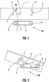
- Fig. 1 illustrates a side view of an exemplary embodiment of a locking mechanism 100 according to this disclosure.
- the locking mechanism 100 includes an alignment structure 3 and a gravity load and locking structure 4 disposed on a side of an article 1 to be locked, and a mounting structure 2 for supporting the article 1.
- the mounting structure 2 is rigidly supported on a fixed surface.
- the mounting structure 2 may be mounted to a workbench or other rigid support.
- the alignment structure 3 is spaced apart from the gravity load and locking structure 4 by a distance associated with a length of the mounting structure 2.
- the alignment structure 3 is configured to be immobile relative to the article 1.
- the alignment structure 3 is integral with the side of the article 1, but in other embodiments, the alignment structure may be a separate component connected to the article 1, such as by a weld, screws, snaps, etc.
- the alignment structure 3 defines an alignment surface A.
- the gravity load and locking structure 4 is movably connected to the side of the article 1 so as to be movable between an open and unlocked state as illustrated in Fig. 1 and a closed and locked position as described in more detail below.
- the gravity load and locking structure 4 is rotatably connected to the article 1, such as by a pivot 102 which can be a pin, bearing, or the like, so as to be rotatable about an axis that is normal to the side of the article 1.
- the gravity load and locking structure 4 is movably connected to the side of the article 1 in other ways.
- the gravity load and locking structure 4 includes a gravity load portion 5 and a first locking surface C that is rotationally offset from the gravity load portion 5 about the axis of rotation of the pin 102.
- the gravity load and locking structure 4 is defined by a first C-shaped curve that includes the gravity load portion 5, and a second C-shaped curve that includes the first locking surface C on an inside thereof.
- the first C-shaped curve is rotationally offset about the pin 102 from the second C-shaped curve, and the top of the first C-shaped curve is connected to the top of the second C-shaped curve.
- the gravity load and locking structure 4 may have other shapes.
- the gravity load and locking structure 4 is configured to be rotationally biased toward an unrestrained position as illustrated in Fig. 1 .
- the gravity load portion 5 of the gravity load and locking structure 4 has a higher weight relative to a remainder of the gravity load and locking structure 4.
- the higher weight may be due to, for example, a different material in the gravity load portion 5, additional material in the gravity load portion 5, or the gravity load portion 5 may be solid while at least a portion of the remainder of the gravity load and locking structure 4 is hollow.
- the higher weight of the gravity load portion 5 creates a moment about the pin 102 that biases the rotational position of gravity load and locking structure 4 due to gravity such that, when unrestrained, the gravity load and locking structure 4 rotates to the unrestrained position in Fig. 1 .
- the gravity load and locking structure is biased toward the unrestrained position via any other acceptable technique, such as via a spring, or via an biasing force applied by a further bias member, for example.
- the mounting structure 2 defines an alignment surface B, a second locking surface D and a load surface F.
- the alignment surface B is on a right side of the mounting structure 2 in Fig. 1 , and is complementary with the alignment surface A, such that the alignment surface B is configured to engage / be received by the alignment surface A.
- the second locking surface D is opposite the alignment surface B, on the left of the mounting structure 2 in Fig. 1 , but in other embodiments, the second locking surface D may be at other locations on the mounting structure 2.
- the second locking surface D is complementary with the first locking surface C, such that the first locking surface C of the gravity load and locking structure 4 is configured to receive / engage the second locking surface D of the mounting structure 2.
- the load surface F extends between the second locking surface D and the alignment surface B on a side of the mounting structure 2 facing the gravity load portion 5.
- the mounting structure 2 is a substantially linear member with rounded ends, although in other embodiments, the mounting structure 2 may have other shapes.
- the alignment surface A of the alignment structure 3 is aligned with the alignment surface B of the mounting structure 2 so that the alignment surface B is received in the alignment structure 3 as illustrated in Fig. 2 .
- the article 1 in Fig. 2 is at an angle relative to the mounting structure 2 so that the gravity load and locking structure 4 is above the alignment structure 3.
- This configuration enables the alignment surface B to be received in the alignment structure 3 without interference from the gravity load and locking structure 4.
- the gravity load portion 5 has rotated the gravity load and locking structure 4 from its positon in Fig. 1 relative to the article 1 since, when unrestrained, the position of the gravity load and locking structure is based on gravity and not on an orientation of the article 1.
- the article 1 is pivoted toward the mounting structure 2 about the alignment surface B.
- the gravity load portion 5 of the gravity load and locking structure 4 defines a load surface E facing toward the load surface F of the mounting structure 2.
- the alignment structure 3 operates as a pivot by which the article 1 may be rotated to move the gravity load and locking structure 4 toward the mounting structure 2.
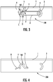
- the article 1 is rotated in a counter-clockwise direction from its position in Fig. 2 to a position in Fig. 3 where the article 1 is level with the mounting structure 2.
- the load surface E of the gravity load portion 5 comes into contact with and bears against the load surface F of the mounting structure 2. Since the mounting structure 2 is rigidly supported, as the article 1 continues to rotate about the alignment structure 3, the pin 102 moves in a downward direction. Because the load surface E of the gravity load portion 5 is restrained by the load surface E of the mounting structure, the continued motion of the article 1 counteracts the biasing force acting on the gravity load and locking surface 4, and causes the gravity load and locking structure 4 to rotate about the pin 102, in this embodiment in a counter-clockwise direction. As least some of counter-action of the biasing force may be due to the weight of the article 1 pushing the article 1 toward the mounting structure 2.
- the rotation of the article 1 causes the locking surface C of the gravity load and locking structure 4 to move toward the locking surface D until the locking surface C comes into contact with the locking surface D, as illustrated in Fig. 3 .
- the locking mechanism 100 is in a closed but unlocked state.
- the locking surface D also acts as a stop for the locking surface C, and delimits a range of motion of the gravity load and locking structure 4.
- the weight of the article is allowed to be supported by the load surface F of the mounting structure via the load surface E of the gravity load and locking structure 4. Because the locking surface C is stopped against the locking surface D, the load surface E can no longer move in response to the action of the load surface F. Thus, the weight of the article biases the load surface E against the load surface F, and results in the locking surface C being biased against the locking surface D so that the mounting structure 2 is held captive between the locking surface C of the gravity load and locking structure 4 and the alignment structure 3.
- the gravity load and locking structure 4 will not be able to rotate toward the unrestrained position until the weight of the article 1 is removed from the load surface F.
- the article 1 is held captive on the mounting structure 2, and the locking mechanism 100 is in a closed and locked state.
- the locking surface C is complementary to the locking surface D, such that the engagement of the locking surfaces C and D results in a form connection, whereby the geometric engagement between the locking surfaces C and D holds the article 1 in place relative to the mounting structure 2.
- the engagement of the locking surfaces C and D results in a force connection, whereby friction between the locking surfaces C and D holds the article 1 in place relative to the mounting structure 2.
- Other types of acceptable engagements are also contemplated, such as via magnets, suction, or the like.
- the locking mechanism 100 automatically engages a locked state due to the weight of the article 1 once the article 1 is properly positioned relative to the mounting structure, and automatically disengages the locked state when the weight of the article 1 is otherwise supported to enable removal of the article 1 from the mounting structure 2.
- the article 1 may be pivoted about the alignment surface B via the alignment structure 3 to move the article 1 from the level position in Fig. 3 toward the angled position in Fig. 2 , whereby the locking mechanism is once again open and unlocked.
- the locking mechanism 100 with the behavior described above is a gravity or weight actuated locking mechanism.
- the state of the locking mechanism is based on not only the mechanical configuration of the locking mechanism 100 or the positions and orientations of the locking mechanism 100 as a whole or the article 1 in particular, but also upon a support condition of the weight of the article 1 to be restrained.
- a locking mechanism 100 it may be desirable to mount an article such as a power tool on a surface such as a workbench, without requiring the manual actuation of a locking mechanism, such that the article is restrained at to both its position and orientation.
- a locking mechanism 100 may align the power tool with a mounting structure 2 that is mounted on the workbench, and release the weight of the power tool. Since the weight of the tool is at least partially supported by the mounting structure 2, the locking mechanism 100 is in a locked state, and the tool cannot be repositioned or reoriented without otherwise supporting the weight of the tool.
- a locking mechanism 100 may also be desirable to remove an article such as a power tool from a surface such as a workbench without requiring the manual release of a locking mechanism.
- a user may lift the article 1 away from the mounting structure 2. The act of lifting the article 1 supports the weight of the article 1, such that the locking mechanism is unlocked, and thus the article 1 may be freely removed.
- Fig. 4 illustrates a side view of another exemplary embodiment of a locking mechanism 200 according to the disclosure that further includes a position engagement structure 6.
- the position engagement structure 6 is connected to the side of the article 1, and is configured to provide an additional bias force on the gravity load and locking structure 4 that biases the gravity load and locking structure toward and/or the unrestrained position.
- an article 1 may be desirably mounted at an orientation at an angle to the level positon in Fig. 2 .
- the article 1 may be subject to external forces, such as motion during transport, vibrations, etc.
- the gravity load and locking structure may undesirably rotate such that the gravity load and locking structure 4 is out of alignment with the mounting structure 2 and thus is unable to allow mounting of the article 1 thereon.
- a user is manipulating an article 1. Such manipulation might otherwise result in the gravity load and locking structure rotating about the pin 102 so that the article 1 cannot be received on the mounting structure 2 in the fashion described above.
- the position engagement structure 6 may be engaged to apply a bias force that acts to bias the gravity load and locking structure toward the unrestrained position to ensure that the article 1 may be mounted despite the motion of the user.
- rotation of the gravity load and locking structure 4 causes the positon engagement structure 6 to disengage, such that after the article 1 is aligned with the mounting structure 2, the bias force of the position engagement structure is no longer applied.
- an article 1 is mounted on a mounting structure 2 in a moving vehicle.
- the weight of the article 1 may be temporarily removed from the mounting structure 2, which might unlock the locking mechanism.
- the position engagement structure 6 may be engaged to apply a bias force that acts to bias the gravity load and locking structure 4 away from the unrestrained position, so that the bias force of the position engagement structure 6 must be overcome in addition to the weight of the article 1 in order to unlock the locking mechanism.
- rotation of the gravity load and locking structure 4 causes the positon engagement structure 6 to disengage, such that after the bias force of the position engagement structure 6 and the weight of the article 1 are overcome, the bias force of the position engagement structure 6 is no longer applied.
- Figs. 5-7 illustrate another exemplary embodiment of a locking mechanism 300 that further includes a safety member 7 and release member 8.
- the safety member 7, once engaged, is configured to fix the gravity load and locking structure 4 in place.
- the safety member 7 enables fixing the gravity load and locking structure 4 in any desired rotational position.
- a user may fix the gravity load and locking structure 4 in an open state to prevent locking of the locking mechanism 300, or may fix the gravity load and locking structure 4 in a closed state to prevent unlocking of the locking mechanism.
- the release member 8 is configured to disengage the safety member 7.
- the position engagement structure 6 is engaged with the gravity load and locking structure 4, and the safety structure 7 that has been disengaged by the release member 8.
- Fig, 6 illustrates the locking mechanism 300 of Fig, 5 whereat the article 1 is properly oriented for mounting with the mounting structure 2. Since the safety member 7 is disengaged, the gravity load and locking structure 4 is free to rotate about the pin 102. In Fig. 7 , the safety member 7 has been engaged, and thus the gravity load and locking structure 4 cannot rotate toward the unrestrained position even when the weight of the article 1 is removed from the mounting structure 2.
- Figs. 8 and 9 illustrate yet another exemplary embodiment of a locking mechanism 400.
- the locking mechanism 400 includes a mounting structure 2 that has external mounting pins 2.
- a pin 2 on the right in Fig. 9 includes the alignment surface B
- a pin 2 on the left in Fig. 9 includes the locking surface D and load surface F, but in other embodiments, the surfaces B, D, and F can be in different locations.
- the gravity load and locking structure 4 is configured to rotate clockwise once the load surface C of the gravity load portion 5 encounters the load surface D of the mounting structure 2, as illustrated by the change in position of the gravity load and locking structure 4 between Figs. 8 and 9 .
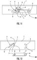
- Figs. 10 and 11 illustrate a further embodiment of a locking mechanism 500.
- the gravity load portion 5 is separate from a locking structure 4.
- the gravity load and locking structure 4 does not move by rotating about an axis normal to the article 1.
- the locking structure 4 is movably mounted be movable laterally relative to the article 1.
- the locking structure 4 has a substantially single curve C-like shape with a linear guide portion H at the top of the C-like shape that is configured to engage the gravity load structure 5.
- the gravity load structure 5 is mounted to the article 1 above the locking structure 4 so as to be movable in a vertical direction relative to the article 1.
- the gravity load structure 5 is a substantially linear member that is oriented at an angle relative to the article 1, toward the right and down in Figs. 10 and 11 , that defines an angled surface G facing toward the linear guide portion H.
- the load surface F of the mounting structure 2 acts on the load surface E of the gravity load structure to move the gravity load structure 5 upwards.
- the angled surface G bears against the linear guide portion H of the locking structure 4 and causes the locking structure 4 to move towards the mounting structure 2, toward the right in Figs. 10 and 11 , until the locking surface C of the locking structure 4 comes into contact with the locking surface D of the mounting structure.
- the locking surface C is urged against the locking surface D, and the article 1 is held captive via the action of the locking structure 4 and alignment structure 3 on the mounting structure 2.
- the article 1 can be mounted on the mounting structure 2 without requiring the article 1 be oriented at an angle. In other words, the article can be positioned vertically above the mounting structure 2 and moved vertically to engage the gravity load structure 5 without any pivoting. Similarly, the article 1 can then be removed from the mounting structure 2 with a vertical motion without any pivoting.
- Figs. 12 and 13 illustrate another exemplary embodiment of a locking mechanism 600 whereby the locking surface D and the second load surface F of the mounting structure form a locking slot, and whereby the locking surface C and first load surface E of the gravity load and locking structure 4 form a locking key 5 configured to engage the locking slot.
- the locking key 5 is rotated into the locking slot so as to engage the locking surface D and hold the article 1 captive on the mounting structure 2.
- Fig. 13 illustrates the locking mechanism 600 of Fig. 12 in the locked state.
- the gravity load and locking structure 4 as illustrated in Fig. 12 includes a gravity load portion 5 that is substantially linear, although other shapes of gravity load and locking structures having a locking key are also contemplated.
- the gravity load portion 5 includes a curved portion having an engagement surface.
- load elements 5 and locking elements 4 are also contemplated.
Description
- This disclosure relates generally to locking mechanisms, and, more particularly, to gravity or weight actuated locking mechanisms, in particular for mounting systems configured to mount power tools onto a work surface.
- Locking mechanisms of various types have long been used for a wide variety of applications. A locking mechanism generally has two states, a locked state, whereby the locking mechanism restrains an article, and an un-locked state, whereby the article is not restrained. An actuation member is generally is operable to switch the locking mechanism between the locked and un-locked states. Different types of locking mechanisms and actuation members may be optimal for different types of applications. For instance, it may be desirable for a locking mechanism to self-engage and automatically switch between the un-locked state and the locked state under certain circumstances, such as the position or orientation of the article, for example.
- In one example,
U.S. Pat. No. 5,123,664 describes a locking mechanism for removably coupling an ice skate runner to a skate shoe without manual manipulation of the locking mechanism. Where a definition or use of a term in a reference is inconsistent or contrary to the definition of that term provided herein, the definition of that term provided herein applies to this disclosure and the definition of that term in the reference does not apply to this disclosure. InU.S. Pat. No. 5,123,664 , a user positions a slot of the runner over a pin on the skate shoe. Stepping into the skate shoe pushes a locking end of the runner into a snap-locking mechanism on the shoe, and the user's weight causes the snap-locking mechanism to engage and lock the locking end of the runner in place. In order to unlock the snap-locking mechanism and remove the runner, the user manually engages a release that disengages the snap-locking mechanism. - In some applications, it is desirable that an article can be released without having to engage a manual release. Self-disengaging locking mechanisms have been developed that are configured to un-lock under certain conditions.
U.S. Pat. No. 5,042,856 describes a locking mechanism for a dumpster lid that uses a counterweight such that when the dumpster is moved from an upright to an inverted position, i.e. when being emptied by a garbage collection truck, gravity acts on the counterweight and unlocks the lid. Other similar examples known in the art include hooks that release at a certain orientation, or moving elements that are brought into an actuation position by gravity when in a certain orientation, such as, for example, the rolling sphere in the gravity locking articulation of a briefcase that unlocks when the briefcase is properly oriented, as described inU.S. Pat. No. 5,369,843 . Some locking mechanisms, such as ski bindings, are designed to automatically release under extreme forces such as those experienced in a ski crash. - However, in some applications, it is desirable to restrain the orientation and position of the article in a way that enables easy installation and removal of the article without manual manipulation of a locking member or release member and without requiring an undue amount of force. In an example, it is often desirable to use a mounting system to mount an article such as a power tool like a miter saw onto a workspace. Such mounting system desirably restrains both the location and orientation of the power tool on the workspace, as movement or rotation may damage a workpiece or the tool, or injure a user. Such systems also desirably provide for easy installation and removal of the tool from the mounting system.
- Various types of mounting systems for power tools have been developed. Generally, such mounting systems either completely restrain the tool, such as by using clamps, bolts, etc., thus requiring manual release of such restraints in order to remove the tool, or only partially restrain the tool, such as by drop-in mounts or groove-and-slide mounts which permit vertical and lateral motion respectively. Therefore, what is needed is a locking mechanism that automatically engages when an article is properly positioned, restrains the location and orientation of the article when engaged, and disengages without requiring use of a manual release.
-
US 2006/0076756 A1 discloses a table saw cart comprised of a framework of a carrier containing multiple lateral and longitudinal frames. -
US 6,666,485 B1 discloses a locking/unlocking device for a waste collection container for automatically locking/unlocking, by gravity. - The following is a brief summary of subject matter described in greater detail herein. This summary is not intended to be limiting as to the scope of this disclosure or to the claims.
According to an embodiment, a gravity locking mechanism having the features ofclaim 1 is provided. - In order to facilitate locking and unlocking an article to and from a mounting system, respectively, without manual actuation of an actuation member, a locking mechanism according to this disclosure is configured so as to be actuated by weight of the article. In other words, the weight of the article actuates the locking mechanism to switch from an unlocked state to a locked state. Additionally, the locking mechanism is disengaged, i.e., switched from the locked state to the unlocked state, when the weight of the article is removed.
- In an embodiment, the mounting structure is rigidly supported on a surface, such as a workbench, wall, or the like, and defines a first alignment surface, a first locking surface, and a first load surface. An article to be locked in terms of orientation and position on the surface includes an alignment structure, a gravity load structure, and a locking structure.
- The alignment structure is fixed to the article, and defines a second alignment surface that, once engaged with the first alignment surface, aligns the article with the mounting structure.
- The gravity load structure is movable on the article, is biased toward an unrestrained position, and defines a second load surface facing toward the mounting structure. As the article moves toward the mounting structure, the second load surface comes into contact with and bears against the first load surface to move the gravity load structure away from the unrestrained position.
- The locking structure is movably attached to the article, and configured such that a movement of the gravity load structure away from and toward the unrestrained position corresponds with a movement of the locking structure toward and away from a closed position respectively. The locking structure defines a second locking surface that engages the first locking surface in the closed position to delimit the corresponding movement of the locking structure and the gravity load structure such that as at least a portion of a weight of the article is supported on the first load surface via the second load surface, the second locking surface is urged against the first locking surface to hold the mounting structure captive between the locking structure and the alignment structure and lock the locking mechanism.
- In an embodiment, the gravity load structure is integral with the locking structure to form a gravity load and locking structure. In an embodiment, the gravity load and locking structure is mounted to the article so as to be pivotable about an axis normal to a side of the article. In an embodiment, the gravity load and locking structure defines a key member configured to be received in a complementary slot defined in the mounting structure in order to engage the mounting structure.
- In another embodiment, the locking structure is configured to move laterally relative to the article, and the gravity load structure is configured to move vertically relative to the article.
- In one embodiment, once the first alignment surface is engaged with the second alignment surface, the alignment structure acts as a pivot to rotate the article toward the mounting structure so that the first load surface bears against the second load surface to move the gravity load structure away from the unrestrained position.
- In another embodiment, the mounting structure is a substantially linear member, where the first alignment surface defines one end of the linear member, the first locking surface defines an opposite end of the linear member, and the load surface defines a side of the linear member therebetween facing toward the gravity load structure.
- In one embodiment, the mounting structure includes a pair of rigidly supported external pins. A first pin includes the first alignment surface, and the alignment structure is configured to engage the first pin. A second pin includes the first load surface and the first locking surface and the gravity load structure and locking structure are configured to engage the second pin.
- In an embodiment, the locking mechanism also includes a position engagement structure configured to apply an additional bias on at least one of the gravity load structure and the locking structure. The addition bias may be configured to act to move the gravity load structure and the locking structure toward the unrestrained position and away from the closed position respectively, or to act to move the gravity load structure and the locking structure away from the unrestrained position and toward the closed position respectively. In one embodiment, the position engagement structure is further configured to disengage the additional bias once the additional bias force is overcome by a counter-acting force.
- In another embodiment, the locking mechanism further includes a safety structure that is configured to engage the gravity load structure and the locking structure to inhibit the movement of the gravity load structure and the locking structure.
- The above presents a simplified summary of this disclosure in order to provide a basic understanding of some aspects of the technologies disclosed herein, and is not an extensive or complete overview of such topics. As such, the summary above does not delineate the scope of this disclosure, and is not intended to identify key or critical aspects of the disclosure. Further details are provided by the detailed description, the claims, and the drawings.
-
-
FIG. 1 is a side view of an exemplary embodiment of a locking mechanism according to the disclosure in an open position. -
FIG. 2 is a side view of the locking mechanism ofFIG. 1 with the article to be mounted properly positioned for mounting using the locking mechanism. -
FIG. 3 is a side view of the locking mechanism ofFIG. 1 in a closed position. -
FIG. 4 is a side view of another exemplary embodiment of a locking mechanism according to the disclosure in an open position. -
FIG. 5 is a side view of a further exemplary embodiment of a locking mechanism according to the disclosure in an open position. -
FIG. 6 is a side view of the locking mechanism ofFIG. 5 with the article to be mounted properly positioned for mounting using the locking mechanism. -
FIG. 7 is a side view of the locking mechanism ofFIG. 5 in a closed position. -
FIG. 8 is a side view of an additional exemplary embodiment of a locking mechanism according to the disclosure in an open position. -
FIG. 9 is a side view of the locking mechanism ofFIG. 8 in a closed position. -
Fig. 10 is a side view of yet another exemplary embodiment of a locking mechanism according to the disclosure in an open position. -
Fig. 11 is a side view of the locking mechanism ofFig. 10 in a closed position. -
Fig. 12 is a side view of a still further exemplary locking mechanism according to the disclosure in an open position. -
Fig. 13 is a side view of the locking mechanism ofFig. 12 in a closed position. -
Fig. 14 is a side view of another exemplary embodiment of a locking mechanism according to the disclosure in an open position. -
Fig. 15 is a side view of the locking mechanism ofFig. 12 in a closed position. - For the purposes of promoting an understanding of the principles of the embodiments described herein, reference is now made to the drawings and descriptions in the following written specification. No limitation to the scope of the subject matter is intended by the references.
-
Fig. 1 illustrates a side view of an exemplary embodiment of alocking mechanism 100 according to this disclosure. Thelocking mechanism 100 includes analignment structure 3 and a gravity load and lockingstructure 4 disposed on a side of anarticle 1 to be locked, and a mountingstructure 2 for supporting thearticle 1. Although not illustrated inFig. 1 , the mountingstructure 2 is rigidly supported on a fixed surface. For example, the mountingstructure 2 may be mounted to a workbench or other rigid support. Thealignment structure 3 is spaced apart from the gravity load and lockingstructure 4 by a distance associated with a length of the mountingstructure 2. - The
alignment structure 3 is configured to be immobile relative to thearticle 1. In this embodiment, thealignment structure 3 is integral with the side of thearticle 1, but in other embodiments, the alignment structure may be a separate component connected to thearticle 1, such as by a weld, screws, snaps, etc. Thealignment structure 3 defines an alignment surface A. - The gravity load and locking
structure 4 is movably connected to the side of thearticle 1 so as to be movable between an open and unlocked state as illustrated inFig. 1 and a closed and locked position as described in more detail below. In this embodiment, the gravity load and lockingstructure 4 is rotatably connected to thearticle 1, such as by apivot 102 which can be a pin, bearing, or the like, so as to be rotatable about an axis that is normal to the side of thearticle 1. In other embodiments such as, for example, some of the other embodiments described below, the gravity load and lockingstructure 4 is movably connected to the side of thearticle 1 in other ways. As illustrated inFig. 1 , the gravity load and lockingstructure 4 includes agravity load portion 5 and a first locking surface C that is rotationally offset from thegravity load portion 5 about the axis of rotation of thepin 102. - In the embodiment illustrated in
Fig. 1 , the gravity load and lockingstructure 4 is defined by a first C-shaped curve that includes thegravity load portion 5, and a second C-shaped curve that includes the first locking surface C on an inside thereof. The first C-shaped curve is rotationally offset about thepin 102 from the second C-shaped curve, and the top of the first C-shaped curve is connected to the top of the second C-shaped curve. In other embodiments, the gravity load and lockingstructure 4 may have other shapes. - The gravity load and locking
structure 4 is configured to be rotationally biased toward an unrestrained position as illustrated inFig. 1 . In this embodiment, thegravity load portion 5 of the gravity load and lockingstructure 4 has a higher weight relative to a remainder of the gravity load and lockingstructure 4. The higher weight may be due to, for example, a different material in thegravity load portion 5, additional material in thegravity load portion 5, or thegravity load portion 5 may be solid while at least a portion of the remainder of the gravity load and lockingstructure 4 is hollow. The higher weight of thegravity load portion 5 creates a moment about thepin 102 that biases the rotational position of gravity load and lockingstructure 4 due to gravity such that, when unrestrained, the gravity load and lockingstructure 4 rotates to the unrestrained position inFig. 1 . - In other embodiments, the gravity load and locking structure is biased toward the unrestrained position via any other acceptable technique, such as via a spring, or via an biasing force applied by a further bias member, for example.
- The mounting
structure 2 defines an alignment surface B, a second locking surface D and a load surface F. The alignment surface B is on a right side of the mountingstructure 2 inFig. 1 , and is complementary with the alignment surface A, such that the alignment surface B is configured to engage / be received by the alignment surface A. - In this embodiment, the second locking surface D is opposite the alignment surface B, on the left of the mounting
structure 2 inFig. 1 , but in other embodiments, the second locking surface D may be at other locations on the mountingstructure 2. The second locking surface D is complementary with the first locking surface C, such that the first locking surface C of the gravity load and lockingstructure 4 is configured to receive / engage the second locking surface D of the mountingstructure 2. The load surface F extends between the second locking surface D and the alignment surface B on a side of the mountingstructure 2 facing thegravity load portion 5. In this embodiment, the mountingstructure 2 is a substantially linear member with rounded ends, although in other embodiments, the mountingstructure 2 may have other shapes. - In order to mount the
article 1 on the mountingstructure 2, the alignment surface A of thealignment structure 3 is aligned with the alignment surface B of the mountingstructure 2 so that the alignment surface B is received in thealignment structure 3 as illustrated inFig. 2 . Thearticle 1 inFig. 2 is at an angle relative to the mountingstructure 2 so that the gravity load and lockingstructure 4 is above thealignment structure 3. This configuration enables the alignment surface B to be received in thealignment structure 3 without interference from the gravity load and lockingstructure 4. As illustrated inFig. 2 , because the gravity load and lockingstructure 4 is unrestrained, thegravity load portion 5 has rotated the gravity load and lockingstructure 4 from its positon inFig. 1 relative to thearticle 1 since, when unrestrained, the position of the gravity load and locking structure is based on gravity and not on an orientation of thearticle 1. - To move the locking mechanism from the open and unlocked state of
Figs. 1 and 2 to a closed but unlocked state illustrated inFig. 3 , thearticle 1 is pivoted toward the mountingstructure 2 about the alignment surface B. Thegravity load portion 5 of the gravity load and lockingstructure 4 defines a load surface E facing toward the load surface F of the mountingstructure 2. Thealignment structure 3 operates as a pivot by which thearticle 1 may be rotated to move the gravity load and lockingstructure 4 toward the mountingstructure 2. In this embodiment, thearticle 1 is rotated in a counter-clockwise direction from its position inFig. 2 to a position inFig. 3 where thearticle 1 is level with the mountingstructure 2. - As the article is rotated from the angled position in
Fig. 2 to the level position inFig. 3 , the load surface E of thegravity load portion 5 comes into contact with and bears against the load surface F of the mountingstructure 2. Since the mountingstructure 2 is rigidly supported, as thearticle 1 continues to rotate about thealignment structure 3, thepin 102 moves in a downward direction. Because the load surface E of thegravity load portion 5 is restrained by the load surface E of the mounting structure, the continued motion of thearticle 1 counteracts the biasing force acting on the gravity load and lockingsurface 4, and causes the gravity load and lockingstructure 4 to rotate about thepin 102, in this embodiment in a counter-clockwise direction. As least some of counter-action of the biasing force may be due to the weight of thearticle 1 pushing thearticle 1 toward the mountingstructure 2. - The rotation of the
article 1 causes the locking surface C of the gravity load and lockingstructure 4 to move toward the locking surface D until the locking surface C comes into contact with the locking surface D, as illustrated inFig. 3 . Once the locking surface C of the gravity load and lockingstructure 4 is in contact with the locking surface D of the mountingstructure 2, as illustrated inFig. 3 , thelocking mechanism 100 is in a closed but unlocked state. The locking surface D also acts as a stop for the locking surface C, and delimits a range of motion of the gravity load and lockingstructure 4. - To move the
locking mechanism 100 from the closed but unlocked state into a closed and locked state, at least a portion of the weight of the article is allowed to be supported by the load surface F of the mounting structure via the load surface E of the gravity load and lockingstructure 4. Because the locking surface C is stopped against the locking surface D, the load surface E can no longer move in response to the action of the load surface F. Thus, the weight of the article biases the load surface E against the load surface F, and results in the locking surface C being biased against the locking surface D so that the mountingstructure 2 is held captive between the locking surface C of the gravity load and lockingstructure 4 and thealignment structure 3. - Once at least a part of the weight of the
article 1 is supported via the load surface E on the load surface F, the gravity load and lockingstructure 4 will not be able to rotate toward the unrestrained position until the weight of thearticle 1 is removed from the load surface F. Thus, thearticle 1 is held captive on the mountingstructure 2, and thelocking mechanism 100 is in a closed and locked state. - For example, in this embodiment, the locking surface C is complementary to the locking surface D, such that the engagement of the locking surfaces C and D results in a form connection, whereby the geometric engagement between the locking surfaces C and D holds the
article 1 in place relative to the mountingstructure 2. In another embodiment, the engagement of the locking surfaces C and D results in a force connection, whereby friction between the locking surfaces C and D holds thearticle 1 in place relative to the mountingstructure 2. Other types of acceptable engagements are also contemplated, such as via magnets, suction, or the like. - Once the
locking mechanism 100 is in the closed and locked state, the angle of thearticle 1 relative to the mountingstructure 2 cannot be changed without the weight of thearticle 1 being removed from the load surface F since the mountingstructure 2 is held captive between thealignment structure 3 and the gravity load and lockingstructure 4. In contrast, when in the closed but unlocked state, thearticle 1 may be freely rotated away from the mountingstructure 1, since the weight of thearticle 1 is otherwise supported. In other words, thelocking mechanism 100 automatically engages a locked state due to the weight of thearticle 1 once thearticle 1 is properly positioned relative to the mounting structure, and automatically disengages the locked state when the weight of thearticle 1 is otherwise supported to enable removal of thearticle 1 from the mountingstructure 2. Once the weight of thearticle 1 is otherwise supported, thearticle 1 may be pivoted about the alignment surface B via thealignment structure 3 to move thearticle 1 from the level position inFig. 3 toward the angled position inFig. 2 , whereby the locking mechanism is once again open and unlocked. - The
locking mechanism 100 with the behavior described above is a gravity or weight actuated locking mechanism. In other words, the state of the locking mechanism is based on not only the mechanical configuration of thelocking mechanism 100 or the positions and orientations of thelocking mechanism 100 as a whole or thearticle 1 in particular, but also upon a support condition of the weight of thearticle 1 to be restrained. - In an exemplary use case, it may be desirable to mount an article such as a power tool on a surface such as a workbench, without requiring the manual actuation of a locking mechanism, such that the article is restrained at to both its position and orientation. By using a
locking mechanism 100 according to this disclosure, a user may align the power tool with a mountingstructure 2 that is mounted on the workbench, and release the weight of the power tool. Since the weight of the tool is at least partially supported by the mountingstructure 2, thelocking mechanism 100 is in a locked state, and the tool cannot be repositioned or reoriented without otherwise supporting the weight of the tool. - It may also be desirable to remove an article such as a power tool from a surface such as a workbench without requiring the manual release of a locking mechanism. By using a
locking mechanism 100 according to this disclosure, a user may lift thearticle 1 away from the mountingstructure 2. The act of lifting thearticle 1 supports the weight of thearticle 1, such that the locking mechanism is unlocked, and thus thearticle 1 may be freely removed. - In the following embodiments of locking mechanisms according to this disclosure, similar elements are referred to with like references. The following embodiments are also described so as to highlight differences from the
locking mechanism 100. Unless stated otherwise, elements in the embodiments below operate and are configured in a similar fashion to like elements in thelocking mechanism 100 described above. -
Fig. 4 illustrates a side view of another exemplary embodiment of alocking mechanism 200 according to the disclosure that further includes aposition engagement structure 6. Theposition engagement structure 6 is connected to the side of thearticle 1, and is configured to provide an additional bias force on the gravity load and lockingstructure 4 that biases the gravity load and locking structure toward and/or the unrestrained position. - In an exemplary use case, an
article 1 may be desirably mounted at an orientation at an angle to the level positon inFig. 2 . In another example, thearticle 1 may be subject to external forces, such as motion during transport, vibrations, etc. In such cases, the gravity load and locking structure may undesirably rotate such that the gravity load and lockingstructure 4 is out of alignment with the mountingstructure 2 and thus is unable to allow mounting of thearticle 1 thereon. - In one example, a user is manipulating an
article 1. Such manipulation might otherwise result in the gravity load and locking structure rotating about thepin 102 so that thearticle 1 cannot be received on the mountingstructure 2 in the fashion described above. Theposition engagement structure 6 may be engaged to apply a bias force that acts to bias the gravity load and locking structure toward the unrestrained position to ensure that thearticle 1 may be mounted despite the motion of the user. In an embodiment, rotation of the gravity load and lockingstructure 4 causes thepositon engagement structure 6 to disengage, such that after thearticle 1 is aligned with the mountingstructure 2, the bias force of the position engagement structure is no longer applied. - In another example, an
article 1 is mounted on a mountingstructure 2 in a moving vehicle. Upon the vehicle hitting a bump, the weight of thearticle 1 may be temporarily removed from the mountingstructure 2, which might unlock the locking mechanism. Theposition engagement structure 6 may be engaged to apply a bias force that acts to bias the gravity load and lockingstructure 4 away from the unrestrained position, so that the bias force of theposition engagement structure 6 must be overcome in addition to the weight of thearticle 1 in order to unlock the locking mechanism. In an embodiment, rotation of the gravity load and lockingstructure 4 causes thepositon engagement structure 6 to disengage, such that after the bias force of theposition engagement structure 6 and the weight of thearticle 1 are overcome, the bias force of theposition engagement structure 6 is no longer applied. -
Figs. 5-7 illustrate another exemplary embodiment of alocking mechanism 300 that further includes asafety member 7 andrelease member 8. Thesafety member 7, once engaged, is configured to fix the gravity load and lockingstructure 4 in place. Thus, thesafety member 7 enables fixing the gravity load and lockingstructure 4 in any desired rotational position. For example, a user may fix the gravity load and lockingstructure 4 in an open state to prevent locking of thelocking mechanism 300, or may fix the gravity load and lockingstructure 4 in a closed state to prevent unlocking of the locking mechanism. Therelease member 8 is configured to disengage thesafety member 7. InFig. 5 , theposition engagement structure 6 is engaged with the gravity load and lockingstructure 4, and thesafety structure 7 that has been disengaged by therelease member 8. -
Fig, 6 illustrates thelocking mechanism 300 ofFig, 5 whereat thearticle 1 is properly oriented for mounting with the mountingstructure 2. Since thesafety member 7 is disengaged, the gravity load and lockingstructure 4 is free to rotate about thepin 102. InFig. 7 , thesafety member 7 has been engaged, and thus the gravity load and lockingstructure 4 cannot rotate toward the unrestrained position even when the weight of thearticle 1 is removed from the mountingstructure 2. - However, it should be understood that releasing of the
safety structure 7 via therelease member 8 does not unlock thelocking mechanism 300. Even when thesafety structure 7 has been disengaged, thelocking mechanism 300 is still in the locked state due to the portion of the weight of thearticle 1 still bearing on the mountingstructure 2. In other words, while thesafety structure 7 can be configured to prevent thelocking mechanism 300 from being unlocked, releasing thesafety structure 7 without removing the portion of weight of thearticle 1 would not itself unlock thelocking mechanism 300. -
Figs. 8 and9 illustrate yet another exemplary embodiment of alocking mechanism 400. As illustrated inFig. 9 , rather than the substantially linear mounting structure described above, thelocking mechanism 400 includes a mountingstructure 2 that has external mounting pins 2. Apin 2 on the right inFig. 9 includes the alignment surface B, and apin 2 on the left inFig. 9 includes the locking surface D and load surface F, but in other embodiments, the surfaces B, D, and F can be in different locations. In the embodiment illustrated inFigs. 8 and9 , the gravity load and lockingstructure 4 is configured to rotate clockwise once the load surface C of thegravity load portion 5 encounters the load surface D of the mountingstructure 2, as illustrated by the change in position of the gravity load and lockingstructure 4 betweenFigs. 8 and9 . -
Figs. 10 and11 illustrate a further embodiment of alocking mechanism 500. In this embodiment, thegravity load portion 5 is separate from a lockingstructure 4. Unlike some other embodiments, the gravity load and lockingstructure 4 does not move by rotating about an axis normal to thearticle 1. - Instead, the locking
structure 4 is movably mounted be movable laterally relative to thearticle 1. In this embodiment, the lockingstructure 4 has a substantially single curve C-like shape with a linear guide portion H at the top of the C-like shape that is configured to engage thegravity load structure 5. - The
gravity load structure 5 is mounted to thearticle 1 above the lockingstructure 4 so as to be movable in a vertical direction relative to thearticle 1. Thegravity load structure 5 is a substantially linear member that is oriented at an angle relative to thearticle 1, toward the right and down inFigs. 10 and11 , that defines an angled surface G facing toward the linear guide portion H. - As the
article 1 moves toward the mountingstructure 2, the load surface F of the mountingstructure 2 acts on the load surface E of the gravity load structure to move thegravity load structure 5 upwards. As thegravity load structure 5 moves upwards, the angled surface G bears against the linear guide portion H of the lockingstructure 4 and causes the lockingstructure 4 to move towards the mountingstructure 2, toward the right inFigs. 10 and11 , until the locking surface C of the lockingstructure 4 comes into contact with the locking surface D of the mounting structure. Once at least a portion of the weight of thearticle 1 bears on the mountingstructure 2, the locking surface C is urged against the locking surface D, and thearticle 1 is held captive via the action of the lockingstructure 4 andalignment structure 3 on the mountingstructure 2. - Because, in the unlocked position shown in
Fig. 10 , the lockingstructure 4 is horizontally spaced away from the locked position shown inFig. 11 (i.e., to the left of the locked position inFig. 11 ), thearticle 1 can be mounted on the mountingstructure 2 without requiring thearticle 1 be oriented at an angle. In other words, the article can be positioned vertically above the mountingstructure 2 and moved vertically to engage thegravity load structure 5 without any pivoting. Similarly, thearticle 1 can then be removed from the mountingstructure 2 with a vertical motion without any pivoting. -
Figs. 12 and13 illustrate another exemplary embodiment of alocking mechanism 600 whereby the locking surface D and the second load surface F of the mounting structure form a locking slot, and whereby the locking surface C and first load surface E of the gravity load and lockingstructure 4 form a locking key 5 configured to engage the locking slot. When the weight of thearticle 1 causes the locking key 5 to bear against the second load surface F, the lockingkey 5 is rotated into the locking slot so as to engage the locking surface D and hold thearticle 1 captive on the mountingstructure 2.Fig. 13 illustrates thelocking mechanism 600 ofFig. 12 in the locked state. The gravity load and lockingstructure 4 as illustrated inFig. 12 includes agravity load portion 5 that is substantially linear, although other shapes of gravity load and locking structures having a locking key are also contemplated. As an example, in an exemplary embodiment of alocking mechanism 700 illustrated inFigs. 14 and15 , thegravity load portion 5 includes a curved portion having an engagement surface. - Other shapes and configurations of
load elements 5 and lockingelements 4 are also contemplated. - While the example of a mounting system configured to mount power tools such as a miter saw to a work surface has been described above, it should be understood that the locking mechanism according to the disclosure can be used for a wide variety of applications, including but not limited to television and picture wall mounts, mountings for kitchen appliances, vehicle cup holders, lid fasteners, weight-actuated locks for chair wheels, and other mounting applications.
Claims (15)
- A gravity locking mechanism (100) comprising a mounting structure (2) and an article (1) removably mountable to the mounting structure (2):wherein the mounting structure (2) that is rigidly supported on a surface, and comprises a first alignment surface (A);a first locking surface (C); anda first load surface (E); andthe article (1) lockable on the surface that includes:an alignment structure (3) fixed to the article (1), that defines a second alignment surface (B) complementary to the first alignment surface (A) that enables alignment of the article (1) with the mounting structure (2) via engagement with the first alignment surface (A);a gravity load structure (5) movably attached to the article (1), that is biased by gravity toward an unrestrained position, and that defines a second load surface (F) configured to bear against the first load surface (E) and move the gravity load structure (5) away from the unrestrained position as the article (1) is moved toward a mounted position relative to the mounting structure (2); anda locking structure (4) movably attached to the article (1), that is configured such that a movement of the gravity load structure (5) away from and toward the unrestrained position corresponds with a movement of the locking structure (4) toward and away from a closed position respectively, and such that the locking structure (4) is in the closed position when the article (1) is in the mounted position,the locking structure (4) defining a second locking surface (D) that engages the first locking surface (C) in the closed position to delimit the corresponding movement of the locking structure (4) and the gravity load structure (5), such that as at least a portion of a weight of the article (1) is supported on the first load surface (E) via the second load surface (F), the second locking surface (D) is urged against the first locking surface (C) to hold the mounting structure (2) captive between the locking structure (4) and the alignment structure and lock the locking mechanism.
- The locking mechanism of claim 1, wherein the gravity load structure (5) is integral with the locking structure (4) to form a gravity load and locking structure (4).
- The locking mechanism of claim 2, wherein the gravity load and locking structure (4) is mounted to the article (1) so as to be pivotable about an axis normal to a side of the article (1).
- The locking mechanism of claim 2, wherein the gravity load and locking structure (4) defines a key member configured to be received in a complementary slot defined in the mounting structure (2) in order to engage the mounting structure (2).
- The locking mechanism of claim 1, wherein the locking structure (4) is configured to move laterally relative to the article (1), and the gravity load structure (5) is configured to move vertically relative to the article (1).
- The locking mechanism of claim 1, further comprising:
an alignment structure (3) fixed to the article (1) and configured to engage with a surface of the mounting structure (2) to align the article (1) with the mounting structure (2). - The locking mechanism of claim 6, wherein in the closed position, the mounting structure (2) is held captive between the alignment structure (3) and the locking structure (4).
- The locking mechanism of claim 7, wherein the alignment structure (3), once engaged with the mounting structure (2), enables the article (1) to pivot about the alignment structure (3) toward the mounting structure (2) and causes the mounting structure (2) to act on the gravity load structure (5) counter to the bias to move the gravity load structure (5) away from the unrestrained position.
- The locking mechanism of claim 6, wherein the alignment structure (3) is adapted to engage a first pin of the mounting structure (2), and the locking structure (4) and gravity load structure (5) each are adapted to engage a second pin of the mounting structure (2).
- The locking mechanism of claim 1, wherein the bias is configured to cause a corresponding movement of the locking device away from the closed position and the gravity load device toward the unrestrained position when the weight of the article (1) is removed from the mounting structure (2) so as not to be supported by the gravity load structure (5) in order to unlock the locking mechanism (100).
- The locking mechanism of claim 1, further comprising:
a position engagement structure (6) configured to apply an additional bias on at least one of the gravity load structure (5) and the locking structure (4). - The locking mechanism of claim 11, wherein the additional bias acts to move the gravity load structure (5) and the locking structure (4) toward the unrestrained position and away from the closed position respectively.
- The locking mechanism of claim 11, wherein the additional bias acts to move the gravity load structure (5) and the locking structure (4) away from the unrestrained position and toward the closed position respectively.
- The locking mechanism of claim 11, wherein the position engagement structure (6) is further adapted to disengage the additional bias once the additional bias force is overcome by a counter-acting force, wherein the position engagement structure (6) is adapted to disengage by rotation of the gravity load and locking structure (4) such that after the article (1) is aligned with the mounting structure (2), the bias force of the position engagement structure is no longer applied.
- The locking mechanism of claim 1, further comprising:
a safety structure (7) that is configured to engage the gravity load structure (5) and the locking structure (4) to inhibit the movement of the gravity load structure (5) and the locking structure (4).
Applications Claiming Priority (2)
| Application Number | Priority Date | Filing Date | Title |
|---|---|---|---|
| US201462069980P | 2014-10-29 | 2014-10-29 | |
| PCT/US2015/057767 WO2016069720A1 (en) | 2014-10-29 | 2015-10-28 | Gravity locking mechanism |
Publications (3)
| Publication Number | Publication Date |
|---|---|
| EP3212868A1 EP3212868A1 (en) | 2017-09-06 |
| EP3212868A4 EP3212868A4 (en) | 2018-07-18 |
| EP3212868B1 true EP3212868B1 (en) | 2020-10-14 |
Family
ID=55851628
Family Applications (1)
| Application Number | Title | Priority Date | Filing Date |
|---|---|---|---|
| EP15853874.4A Active EP3212868B1 (en) | 2014-10-29 | 2015-10-28 | Gravity locking mechanism |
Country Status (3)
| Country | Link |
|---|---|
| US (1) | US10350745B2 (en) |
| EP (1) | EP3212868B1 (en) |
| WO (1) | WO2016069720A1 (en) |
Families Citing this family (1)
| Publication number | Priority date | Publication date | Assignee | Title |
|---|---|---|---|---|
| WO2015061370A1 (en) | 2013-10-21 | 2015-04-30 | Milwaukee Electric Tool Corporation | Adapter for power tool devices |
Citations (1)
| Publication number | Priority date | Publication date | Assignee | Title |
|---|---|---|---|---|
| US2627435A (en) * | 1951-02-06 | 1953-02-03 | Frederik J Borrup | Automatic lock |
Family Cites Families (24)
| Publication number | Priority date | Publication date | Assignee | Title |
|---|---|---|---|---|
| US1490874A (en) * | 1923-10-20 | 1924-04-15 | Nettlefold & Sons Ltd | Catch for windows or the like |
| US2697389A (en) | 1949-04-11 | 1954-12-21 | Earle D Heckman | Lock type manhole cover |
| US3642314A (en) | 1970-03-18 | 1972-02-15 | Overhead Door Corp | Gravity-actuated lock |
| US5042856A (en) | 1990-04-27 | 1991-08-27 | Goodman Lowell R | Automatic locking mechanism for dumpster lid |
| US5123664A (en) | 1991-02-04 | 1992-06-23 | Demars Daniel G | Snap lock, step in, replacement skate runner |
| US5094578A (en) | 1991-02-04 | 1992-03-10 | Master Industries, Inc. | Self-locking retainer clip |
| US5201445A (en) | 1991-05-20 | 1993-04-13 | Axelman Bart I | Tool holder with self-stabilizing swivel mount |
| US5415314A (en) * | 1993-06-21 | 1995-05-16 | Mccollum; Chris A. | Gravity locking mechanism employing first and second pendulums for securing the lid of a refuse container |
| US5369843A (en) | 1993-09-29 | 1994-12-06 | Yu; Johnson C. T. | Gravity locking articulation for a briefcase |
| GB2286626B (en) * | 1994-02-11 | 1997-09-24 | Autoliv Dev | Improvements in or relating to a locking arrangement |
| US5419598A (en) * | 1994-04-28 | 1995-05-30 | Kreitzer; Joseph D. | Lock for trash bin |
| US5586008A (en) | 1994-09-06 | 1996-12-17 | Methode Electronics, Inc. | Gravity latch for surface mount components |
| US5513862A (en) * | 1994-11-29 | 1996-05-07 | Chuang; Chien-Hsiung | Skate with wedge-shaped height adjuster |
| DE29806599U1 (en) * | 1998-04-09 | 1998-07-16 | Ms Trade Gmbh & Co Kissmark Sp | Snowboard entry binding |
| FR2798120B1 (en) * | 1999-09-03 | 2001-11-16 | Citec Environnement | AUTOMATIC DEVICE BY GRAVITY OF LOCKING / UNLOCKING THE COVER OF A TRAY AND TRAY EQUIPPED WITH SUCH A DEVICE |
| US6397534B1 (en) | 2000-06-12 | 2002-06-04 | Steelcase Development Corporation | Cover member lock for partition panels |
| DE60237685D1 (en) * | 2001-06-29 | 2010-10-28 | Mission Itech Hockey Inc | SLIDING CHASSIS WITH TILTING CONTROL |
| US7213829B2 (en) * | 2004-09-24 | 2007-05-08 | Super Made Products Co., Ltd. | Table saw cart |
| US7416421B2 (en) | 2006-07-31 | 2008-08-26 | Automation Components, Inc. | Enclosure with integral snap acting mounting feet |
| DE102009020717B4 (en) * | 2009-05-11 | 2013-09-26 | Gerhard Weusthof | chop saw |
| CN201555001U (en) | 2009-08-18 | 2010-08-18 | 宁波丽晶时代电子线缆有限公司 | Flat panel television wall-mounted frame with self-locking dropping-proof function |
| US20100148523A1 (en) * | 2010-02-26 | 2010-06-17 | Chi-Chih Tai | Gate Latch |
| US8984818B2 (en) | 2010-10-06 | 2015-03-24 | Sunrun South Llc | Snap-in mounting systems for laminate solar panels |
| US8454030B2 (en) * | 2011-01-25 | 2013-06-04 | Bauer Hockey, Inc. | Ice skate blade assembly |
-
2015
- 2015-10-28 EP EP15853874.4A patent/EP3212868B1/en active Active
- 2015-10-28 WO PCT/US2015/057767 patent/WO2016069720A1/en active Application Filing
- 2015-10-28 US US14/925,013 patent/US10350745B2/en active Active
Patent Citations (1)
| Publication number | Priority date | Publication date | Assignee | Title |
|---|---|---|---|---|
| US2627435A (en) * | 1951-02-06 | 1953-02-03 | Frederik J Borrup | Automatic lock |
Also Published As
| Publication number | Publication date |
|---|---|
| EP3212868A4 (en) | 2018-07-18 |
| EP3212868A1 (en) | 2017-09-06 |
| WO2016069720A1 (en) | 2016-05-06 |
| US10350745B2 (en) | 2019-07-16 |
| US20160121477A1 (en) | 2016-05-05 |
Similar Documents
| Publication | Publication Date | Title |
|---|---|---|
| AU2020204281B2 (en) | Container mounting assembly | |
| US8070181B2 (en) | Convertible cart | |
| US7681893B2 (en) | Folding support for table machine | |
| US20090174162A1 (en) | Mobile base for a table saw | |
| AU2018202637B2 (en) | Electrode assembly for measurement of platelet function in whole blood | |
| WO2004091993A2 (en) | Hand truck, step ladder and dolly device | |
| US8794454B2 (en) | Bicycle storage system | |
| EP3212868B1 (en) | Gravity locking mechanism | |
| US20080142658A1 (en) | Baseframe With Attachment | |
| CN109572788B (en) | Gearbox repair trolley | |
| US20080073304A1 (en) | Collapsible transport frame | |
| EP2258601B1 (en) | System and method for detachably mounting an infant carrier device on a support structure | |
| CN209834043U (en) | Turnover equipment | |
| JPS6326045Y2 (en) | ||
| GB2400088A (en) | Releasable attachment system for a container | |
| JP2011046281A (en) | Conveying carriage apparatus | |
| CN211308626U (en) | Prevent slow-witted type turnover vehicle | |
| CN220253397U (en) | Pull formula bears module and battery package frame | |
| EP2045165A2 (en) | Wheelbarrow | |
| CN213262926U (en) | Inertia control mechanism | |
| JPH07230A (en) | Table | |
| JPS6328908Y2 (en) | ||
| JPH0535567Y2 (en) | ||
| CA2571634A1 (en) | Baseframe with attachment | |
| WO2013020018A1 (en) | Bicycle storage system |
Legal Events
| Date | Code | Title | Description |
|---|---|---|---|
| STAA | Information on the status of an ep patent application or granted ep patent |
Free format text: STATUS: THE INTERNATIONAL PUBLICATION HAS BEEN MADE |
|
| PUAI | Public reference made under article 153(3) epc to a published international application that has entered the european phase |
Free format text: ORIGINAL CODE: 0009012 |
|
| STAA | Information on the status of an ep patent application or granted ep patent |
Free format text: STATUS: REQUEST FOR EXAMINATION WAS MADE |
|
| 17P | Request for examination filed |
Effective date: 20170529 |
|
| AK | Designated contracting states |
Kind code of ref document: A1 Designated state(s): AL AT BE BG CH CY CZ DE DK EE ES FI FR GB GR HR HU IE IS IT LI LT LU LV MC MK MT NL NO PL PT RO RS SE SI SK SM TR |
|
| AX | Request for extension of the european patent |
Extension state: BA ME |
|
| RAP1 | Party data changed (applicant data changed or rights of an application transferred) |
Owner name: ROBERT BOSCH GMBH |
|
| DAV | Request for validation of the european patent (deleted) | ||
| DAX | Request for extension of the european patent (deleted) | ||
| REG | Reference to a national code |
Ref country code: DE Ref legal event code: R079 Ref document number: 602015060598 Country of ref document: DE Free format text: PREVIOUS MAIN CLASS: E05B0063000000 Ipc: F16M0011040000 |
|
| A4 | Supplementary search report drawn up and despatched |
Effective date: 20180614 |
|
| RIC1 | Information provided on ipc code assigned before grant |
Ipc: B25H 1/08 20060101ALI20180608BHEP Ipc: F16M 11/04 20060101AFI20180608BHEP |
|
| RAP1 | Party data changed (applicant data changed or rights of an application transferred) |
Owner name: ROBERT BOSCH GMBH |
|
| GRAP | Despatch of communication of intention to grant a patent |
Free format text: ORIGINAL CODE: EPIDOSNIGR1 |
|
| STAA | Information on the status of an ep patent application or granted ep patent |
Free format text: STATUS: GRANT OF PATENT IS INTENDED |
|
| INTG | Intention to grant announced |
Effective date: 20200504 |
|
| GRAS | Grant fee paid |
Free format text: ORIGINAL CODE: EPIDOSNIGR3 |
|
| GRAA | (expected) grant |
Free format text: ORIGINAL CODE: 0009210 |
|
| STAA | Information on the status of an ep patent application or granted ep patent |
Free format text: STATUS: THE PATENT HAS BEEN GRANTED |
|
| AK | Designated contracting states |
Kind code of ref document: B1 Designated state(s): AL AT BE BG CH CY CZ DE DK EE ES FI FR GB GR HR HU IE IS IT LI LT LU LV MC MK MT NL NO PL PT RO RS SE SI SK SM TR |
|
| REG | Reference to a national code |
Ref country code: GB Ref legal event code: FG4D |
|
| REG | Reference to a national code |
Ref country code: AT Ref legal event code: REF Ref document number: 1323928 Country of ref document: AT Kind code of ref document: T Effective date: 20201015 Ref country code: CH Ref legal event code: EP |
|
| REG | Reference to a national code |
Ref country code: DE Ref legal event code: R096 Ref document number: 602015060598 Country of ref document: DE |
|
| REG | Reference to a national code |
Ref country code: IE Ref legal event code: FG4D |
|
| REG | Reference to a national code |
Ref country code: AT Ref legal event code: MK05 Ref document number: 1323928 Country of ref document: AT Kind code of ref document: T Effective date: 20201014 |
|
| REG | Reference to a national code |
Ref country code: NL Ref legal event code: MP Effective date: 20201014 |
|
| PG25 | Lapsed in a contracting state [announced via postgrant information from national office to epo] |
Ref country code: FI Free format text: LAPSE BECAUSE OF FAILURE TO SUBMIT A TRANSLATION OF THE DESCRIPTION OR TO PAY THE FEE WITHIN THE PRESCRIBED TIME-LIMIT Effective date: 20201014 Ref country code: PT Free format text: LAPSE BECAUSE OF FAILURE TO SUBMIT A TRANSLATION OF THE DESCRIPTION OR TO PAY THE FEE WITHIN THE PRESCRIBED TIME-LIMIT Effective date: 20210215 Ref country code: RS Free format text: LAPSE BECAUSE OF FAILURE TO SUBMIT A TRANSLATION OF THE DESCRIPTION OR TO PAY THE FEE WITHIN THE PRESCRIBED TIME-LIMIT Effective date: 20201014 Ref country code: NO Free format text: LAPSE BECAUSE OF FAILURE TO SUBMIT A TRANSLATION OF THE DESCRIPTION OR TO PAY THE FEE WITHIN THE PRESCRIBED TIME-LIMIT Effective date: 20210114 Ref country code: NL Free format text: LAPSE BECAUSE OF FAILURE TO SUBMIT A TRANSLATION OF THE DESCRIPTION OR TO PAY THE FEE WITHIN THE PRESCRIBED TIME-LIMIT Effective date: 20201014 Ref country code: GR Free format text: LAPSE BECAUSE OF FAILURE TO SUBMIT A TRANSLATION OF THE DESCRIPTION OR TO PAY THE FEE WITHIN THE PRESCRIBED TIME-LIMIT Effective date: 20210115 |
|
| REG | Reference to a national code |
Ref country code: LT Ref legal event code: MG4D |
|
| PG25 | Lapsed in a contracting state [announced via postgrant information from national office to epo] |
Ref country code: AT Free format text: LAPSE BECAUSE OF FAILURE TO SUBMIT A TRANSLATION OF THE DESCRIPTION OR TO PAY THE FEE WITHIN THE PRESCRIBED TIME-LIMIT Effective date: 20201014 Ref country code: ES Free format text: LAPSE BECAUSE OF FAILURE TO SUBMIT A TRANSLATION OF THE DESCRIPTION OR TO PAY THE FEE WITHIN THE PRESCRIBED TIME-LIMIT Effective date: 20201014 Ref country code: BG Free format text: LAPSE BECAUSE OF FAILURE TO SUBMIT A TRANSLATION OF THE DESCRIPTION OR TO PAY THE FEE WITHIN THE PRESCRIBED TIME-LIMIT Effective date: 20210114 Ref country code: PL Free format text: LAPSE BECAUSE OF FAILURE TO SUBMIT A TRANSLATION OF THE DESCRIPTION OR TO PAY THE FEE WITHIN THE PRESCRIBED TIME-LIMIT Effective date: 20201014 Ref country code: LV Free format text: LAPSE BECAUSE OF FAILURE TO SUBMIT A TRANSLATION OF THE DESCRIPTION OR TO PAY THE FEE WITHIN THE PRESCRIBED TIME-LIMIT Effective date: 20201014 Ref country code: IS Free format text: LAPSE BECAUSE OF FAILURE TO SUBMIT A TRANSLATION OF THE DESCRIPTION OR TO PAY THE FEE WITHIN THE PRESCRIBED TIME-LIMIT Effective date: 20210214 Ref country code: SE Free format text: LAPSE BECAUSE OF FAILURE TO SUBMIT A TRANSLATION OF THE DESCRIPTION OR TO PAY THE FEE WITHIN THE PRESCRIBED TIME-LIMIT Effective date: 20201014 |
|
| REG | Reference to a national code |
Ref country code: CH Ref legal event code: PL |
|
| PG25 | Lapsed in a contracting state [announced via postgrant information from national office to epo] |
Ref country code: LU Free format text: LAPSE BECAUSE OF NON-PAYMENT OF DUE FEES Effective date: 20201028 Ref country code: HR Free format text: LAPSE BECAUSE OF FAILURE TO SUBMIT A TRANSLATION OF THE DESCRIPTION OR TO PAY THE FEE WITHIN THE PRESCRIBED TIME-LIMIT Effective date: 20201014 |
|
| REG | Reference to a national code |
Ref country code: DE Ref legal event code: R097 Ref document number: 602015060598 Country of ref document: DE Ref country code: BE Ref legal event code: MM Effective date: 20201031 |
|
| PG25 | Lapsed in a contracting state [announced via postgrant information from national office to epo] |
Ref country code: MC Free format text: LAPSE BECAUSE OF FAILURE TO SUBMIT A TRANSLATION OF THE DESCRIPTION OR TO PAY THE FEE WITHIN THE PRESCRIBED TIME-LIMIT Effective date: 20201014 Ref country code: LT Free format text: LAPSE BECAUSE OF FAILURE TO SUBMIT A TRANSLATION OF THE DESCRIPTION OR TO PAY THE FEE WITHIN THE PRESCRIBED TIME-LIMIT Effective date: 20201014 Ref country code: SM Free format text: LAPSE BECAUSE OF FAILURE TO SUBMIT A TRANSLATION OF THE DESCRIPTION OR TO PAY THE FEE WITHIN THE PRESCRIBED TIME-LIMIT Effective date: 20201014 Ref country code: CZ Free format text: LAPSE BECAUSE OF FAILURE TO SUBMIT A TRANSLATION OF THE DESCRIPTION OR TO PAY THE FEE WITHIN THE PRESCRIBED TIME-LIMIT Effective date: 20201014 Ref country code: EE Free format text: LAPSE BECAUSE OF FAILURE TO SUBMIT A TRANSLATION OF THE DESCRIPTION OR TO PAY THE FEE WITHIN THE PRESCRIBED TIME-LIMIT Effective date: 20201014 Ref country code: RO Free format text: LAPSE BECAUSE OF FAILURE TO SUBMIT A TRANSLATION OF THE DESCRIPTION OR TO PAY THE FEE WITHIN THE PRESCRIBED TIME-LIMIT Effective date: 20201014 Ref country code: SK Free format text: LAPSE BECAUSE OF FAILURE TO SUBMIT A TRANSLATION OF THE DESCRIPTION OR TO PAY THE FEE WITHIN THE PRESCRIBED TIME-LIMIT Effective date: 20201014 |
|
| PLBE | No opposition filed within time limit |
Free format text: ORIGINAL CODE: 0009261 |
|
| STAA | Information on the status of an ep patent application or granted ep patent |
Free format text: STATUS: NO OPPOSITION FILED WITHIN TIME LIMIT |
|
| PG25 | Lapsed in a contracting state [announced via postgrant information from national office to epo] |
Ref country code: LI Free format text: LAPSE BECAUSE OF NON-PAYMENT OF DUE FEES Effective date: 20201031 Ref country code: DK Free format text: LAPSE BECAUSE OF FAILURE TO SUBMIT A TRANSLATION OF THE DESCRIPTION OR TO PAY THE FEE WITHIN THE PRESCRIBED TIME-LIMIT Effective date: 20201014 Ref country code: CH Free format text: LAPSE BECAUSE OF NON-PAYMENT OF DUE FEES Effective date: 20201031 Ref country code: BE Free format text: LAPSE BECAUSE OF NON-PAYMENT OF DUE FEES Effective date: 20201031 |
|
| 26N | No opposition filed |
Effective date: 20210715 |
|
| PG25 | Lapsed in a contracting state [announced via postgrant information from national office to epo] |
Ref country code: IE Free format text: LAPSE BECAUSE OF NON-PAYMENT OF DUE FEES Effective date: 20201028 Ref country code: IT Free format text: LAPSE BECAUSE OF FAILURE TO SUBMIT A TRANSLATION OF THE DESCRIPTION OR TO PAY THE FEE WITHIN THE PRESCRIBED TIME-LIMIT Effective date: 20201014 Ref country code: AL Free format text: LAPSE BECAUSE OF FAILURE TO SUBMIT A TRANSLATION OF THE DESCRIPTION OR TO PAY THE FEE WITHIN THE PRESCRIBED TIME-LIMIT Effective date: 20201014 |
|
| PG25 | Lapsed in a contracting state [announced via postgrant information from national office to epo] |
Ref country code: SI Free format text: LAPSE BECAUSE OF FAILURE TO SUBMIT A TRANSLATION OF THE DESCRIPTION OR TO PAY THE FEE WITHIN THE PRESCRIBED TIME-LIMIT Effective date: 20201014 |
|
| PG25 | Lapsed in a contracting state [announced via postgrant information from national office to epo] |
Ref country code: IS Free format text: LAPSE BECAUSE OF FAILURE TO SUBMIT A TRANSLATION OF THE DESCRIPTION OR TO PAY THE FEE WITHIN THE PRESCRIBED TIME-LIMIT Effective date: 20210214 Ref country code: TR Free format text: LAPSE BECAUSE OF FAILURE TO SUBMIT A TRANSLATION OF THE DESCRIPTION OR TO PAY THE FEE WITHIN THE PRESCRIBED TIME-LIMIT Effective date: 20201014 Ref country code: MT Free format text: LAPSE BECAUSE OF FAILURE TO SUBMIT A TRANSLATION OF THE DESCRIPTION OR TO PAY THE FEE WITHIN THE PRESCRIBED TIME-LIMIT Effective date: 20201014 Ref country code: CY Free format text: LAPSE BECAUSE OF FAILURE TO SUBMIT A TRANSLATION OF THE DESCRIPTION OR TO PAY THE FEE WITHIN THE PRESCRIBED TIME-LIMIT Effective date: 20201014 |
|
| PG25 | Lapsed in a contracting state [announced via postgrant information from national office to epo] |
Ref country code: MK Free format text: LAPSE BECAUSE OF FAILURE TO SUBMIT A TRANSLATION OF THE DESCRIPTION OR TO PAY THE FEE WITHIN THE PRESCRIBED TIME-LIMIT Effective date: 20201014 |
|
| PGFP | Annual fee paid to national office [announced via postgrant information from national office to epo] |
Ref country code: DE Payment date: 20221215 Year of fee payment: 8 |
|
| PGFP | Annual fee paid to national office [announced via postgrant information from national office to epo] |
Ref country code: GB Payment date: 20231025 Year of fee payment: 9 |
|
| PGFP | Annual fee paid to national office [announced via postgrant information from national office to epo] |
Ref country code: FR Payment date: 20231023 Year of fee payment: 9 |