EP3211766A1 - Electric generator, foundation pedestal for electric generator and maintenance method for electric generator - Google Patents
Electric generator, foundation pedestal for electric generator and maintenance method for electric generator Download PDFInfo
- Publication number
- EP3211766A1 EP3211766A1 EP17158240.6A EP17158240A EP3211766A1 EP 3211766 A1 EP3211766 A1 EP 3211766A1 EP 17158240 A EP17158240 A EP 17158240A EP 3211766 A1 EP3211766 A1 EP 3211766A1
- Authority
- EP
- European Patent Office
- Prior art keywords
- electric generator
- foundation pedestal
- carrier device
- foundation
- floor face
- Prior art date
- Legal status (The legal status is an assumption and is not a legal conclusion. Google has not performed a legal analysis and makes no representation as to the accuracy of the status listed.)
- Granted
Links
Images




Classifications
-
- H—ELECTRICITY
- H02—GENERATION; CONVERSION OR DISTRIBUTION OF ELECTRIC POWER
- H02K—DYNAMO-ELECTRIC MACHINES
- H02K15/00—Processes or apparatus specially adapted for manufacturing, assembling, maintaining or repairing of dynamo-electric machines
- H02K15/50—Disassembling, repairing or modifying dynamo-electric machines
-
- B—PERFORMING OPERATIONS; TRANSPORTING
- B65—CONVEYING; PACKING; STORING; HANDLING THIN OR FILAMENTARY MATERIAL
- B65G—TRANSPORT OR STORAGE DEVICES, e.g. CONVEYORS FOR LOADING OR TIPPING, SHOP CONVEYOR SYSTEMS OR PNEUMATIC TUBE CONVEYORS
- B65G7/00—Devices for assisting manual moving or tilting heavy loads
- B65G7/02—Devices adapted to be interposed between loads and the ground or floor, e.g. crowbars with means for assisting conveyance of loads
- B65G7/04—Rollers
-
- B—PERFORMING OPERATIONS; TRANSPORTING
- B65—CONVEYING; PACKING; STORING; HANDLING THIN OR FILAMENTARY MATERIAL
- B65G—TRANSPORT OR STORAGE DEVICES, e.g. CONVEYORS FOR LOADING OR TIPPING, SHOP CONVEYOR SYSTEMS OR PNEUMATIC TUBE CONVEYORS
- B65G7/00—Devices for assisting manual moving or tilting heavy loads
- B65G7/02—Devices adapted to be interposed between loads and the ground or floor, e.g. crowbars with means for assisting conveyance of loads
- B65G7/06—Devices adapted to be interposed between loads and the ground or floor, e.g. crowbars with means for assisting conveyance of loads using fluid at high pressure supplied from an independent source to provide a cushion between load and ground
-
- F—MECHANICAL ENGINEERING; LIGHTING; HEATING; WEAPONS; BLASTING
- F01—MACHINES OR ENGINES IN GENERAL; ENGINE PLANTS IN GENERAL; STEAM ENGINES
- F01D—NON-POSITIVE DISPLACEMENT MACHINES OR ENGINES, e.g. STEAM TURBINES
- F01D15/00—Adaptations of machines or engines for special use; Combinations of engines with devices driven thereby
- F01D15/10—Adaptations for driving, or combinations with, electric generators
-
- F—MECHANICAL ENGINEERING; LIGHTING; HEATING; WEAPONS; BLASTING
- F01—MACHINES OR ENGINES IN GENERAL; ENGINE PLANTS IN GENERAL; STEAM ENGINES
- F01D—NON-POSITIVE DISPLACEMENT MACHINES OR ENGINES, e.g. STEAM TURBINES
- F01D25/00—Component parts, details, or accessories, not provided for in, or of interest apart from, other groups
- F01D25/28—Supporting or mounting arrangements, e.g. for turbine casing
- F01D25/285—Temporary support structures, e.g. for testing, assembling, installing, repairing; Assembly methods using such structures
-
- F—MECHANICAL ENGINEERING; LIGHTING; HEATING; WEAPONS; BLASTING
- F16—ENGINEERING ELEMENTS AND UNITS; GENERAL MEASURES FOR PRODUCING AND MAINTAINING EFFECTIVE FUNCTIONING OF MACHINES OR INSTALLATIONS; THERMAL INSULATION IN GENERAL
- F16M—FRAMES, CASINGS OR BEDS OF ENGINES, MACHINES OR APPARATUS, NOT SPECIFIC TO ENGINES, MACHINES OR APPARATUS PROVIDED FOR ELSEWHERE; STANDS; SUPPORTS
- F16M7/00—Details of attaching or adjusting engine beds, frames, or supporting-legs on foundation or base; Attaching non-moving engine parts, e.g. cylinder blocks
-
- F—MECHANICAL ENGINEERING; LIGHTING; HEATING; WEAPONS; BLASTING
- F16—ENGINEERING ELEMENTS AND UNITS; GENERAL MEASURES FOR PRODUCING AND MAINTAINING EFFECTIVE FUNCTIONING OF MACHINES OR INSTALLATIONS; THERMAL INSULATION IN GENERAL
- F16M—FRAMES, CASINGS OR BEDS OF ENGINES, MACHINES OR APPARATUS, NOT SPECIFIC TO ENGINES, MACHINES OR APPARATUS PROVIDED FOR ELSEWHERE; STANDS; SUPPORTS
- F16M9/00—Special layout of foundations with respect to machinery to be supported
-
- H—ELECTRICITY
- H02—GENERATION; CONVERSION OR DISTRIBUTION OF ELECTRIC POWER
- H02K—DYNAMO-ELECTRIC MACHINES
- H02K15/00—Processes or apparatus specially adapted for manufacturing, assembling, maintaining or repairing of dynamo-electric machines
-
- H—ELECTRICITY
- H02—GENERATION; CONVERSION OR DISTRIBUTION OF ELECTRIC POWER
- H02K—DYNAMO-ELECTRIC MACHINES
- H02K5/00—Casings; Enclosures; Supports
-
- H—ELECTRICITY
- H02—GENERATION; CONVERSION OR DISTRIBUTION OF ELECTRIC POWER
- H02K—DYNAMO-ELECTRIC MACHINES
- H02K5/00—Casings; Enclosures; Supports
- H02K5/26—Means for adjusting casings relative to their supports
-
- F—MECHANICAL ENGINEERING; LIGHTING; HEATING; WEAPONS; BLASTING
- F05—INDEXING SCHEMES RELATING TO ENGINES OR PUMPS IN VARIOUS SUBCLASSES OF CLASSES F01-F04
- F05D—INDEXING SCHEME FOR ASPECTS RELATING TO NON-POSITIVE-DISPLACEMENT MACHINES OR ENGINES, GAS-TURBINES OR JET-PROPULSION PLANTS
- F05D2230/00—Manufacture
- F05D2230/72—Maintenance
-
- H—ELECTRICITY
- H02—GENERATION; CONVERSION OR DISTRIBUTION OF ELECTRIC POWER
- H02K—DYNAMO-ELECTRIC MACHINES
- H02K15/00—Processes or apparatus specially adapted for manufacturing, assembling, maintaining or repairing of dynamo-electric machines
- H02K15/02—Processes or apparatus specially adapted for manufacturing, assembling, maintaining or repairing of dynamo-electric machines of stator or rotor bodies
Definitions
- Embodiments described herein relate generally to an electric generator, a foundation pedestal for an electric generator, and a maintenance method for an electric generator.
- Single-shaft type combined cycle power plants which drive a single electric generator by a gas turbine and a steam turbine include a form in which the gas turbine and the steam turbine are connected via a single shaft with the electric generator located therebetween.
- a rotor For the maintenance of an electric generator, a rotor is pulled out of a stator of the electric generator, and the rotor and the stator undergo internal inspection and repair. At this time, a space for pulling out the rotor in the axial direction is required on one axial end side of the electric generator.
- a space for pulling out the rotor cannot be obtained due to the presence of the engines at both of its ends. As such, there is a drawback that one of the engines, i.e., the gas turbine or the steam turbine, must be disassembled at the time of the maintenance of the electric generator.
- a method that does not require disassembly of the engines (hereinafter called a "first method") is known.
- a temporary work floor is constructed above either engine, the electric generator is lifted up by a portal crane, and the rotor of the electric generator is pulled out onto the temporary work floor to conduct inspection of the electric generator.
- a platform is provided above the steam turbine, then the electric generator is lifted up to the level of the platform by a temporary gantry crane, etc., then the electric generator is placed on a temporary support column, and the rotor is pulled out onto the platform to conduct inspection of the electric generator.
- a further method that does not require disassembly of the engines (hereinafter called a "third method") is known.
- the electric generator is raised with a jack to form a gap between it and a foundation pedestal, the foundation for the electric generator is provided with a temporary rail in an axially perpendicular direction, a wheeled dolly to run on the rail is placed at the lower portion of the electric generator, the electric generator is laterally moved to the position where pulling of the rotor of the electric generator does not interfere with the engine, and thereafter the rotor is pulled out to conduct the maintenance of the electric generator.
- the first method and the second method involve many auxiliary operations for the maintenance of an electric generator, such as installation of a temporary work floor (platform) and a temporary crane, and as such, they incur additional costs and work time and also create a problem of safety due to high uplift of the electric generator. Furthermore, providing the temporary work floor (platform) above the steam turbine leads to a problem of posing limitations on the maintenance of the steam turbine.
- the third method involves many auxiliary operations for the axially perpendicular movement of the electric generator, such as jacking up the electric generator, installation of the temporary rail and attachment of the wheeled dolly, and as such, it incurs additional costs and work time and also creates a problem of increasing items to be checked for safety relating to, for example, strength of the temporary rail onto which a load is concentrated.
- a maintenance method for an electric generator applied to a power plant in which both axial ends of the electric generator are connected to respective rotary machines includes: providing the electric generator with leg plates for placing the electric generator on a floor face of a foundation pedestal, forming a bottom portion of the electric generator to have a bottom plane capable of supporting a weight of the electric generator, and forming a gap between the bottom plane of the electric generator and an opposing floor face of the foundation pedestal such that a carrier device capable of lifting up and horizontally moving the electric generator can be inserted into the gap while the electric generator is placed on the floor face of the foundation pedestal via the leg plates; and providing the carrier device in the gap, lifting up and horizontally moving the electric generator by the carrier device, and thereafter doing maintenance of the electric generator.
- FIG. 1 is a side view showing the shafting structure of a single-shaft type combined cycle power plant (combined-cycle power plant) adopting an electric generator driven at both ends according to one embodiment.
- This plant is a combined-cycle power plant which drives an electric generator by a gas turbine and a steam turbine, wherein a gas turbine 32, and a medium-to-high pressure steam turbine 36 and a low pressure steam turbine 37 are disposed at the respective ends of an electric generator 34, connected to each other via an intermediate shaft 33, a clutch 35, or the like, and linearly arranged on one axis as shown in FIG. 1 . Also, the gas turbine 32, the medium-to-high pressure steam turbine 36, the low pressure steam turbine 37, and the electric generator 34 are each installed on foundation pedestals 38 and 6 made of, for example, reinforced concrete, as shown in FIG. 1 .
- FIG. 2 shows the structure of the electric generator according to this embodiment.
- an electric generator to take, regarding the extracting direction of a terminal for extracting generated electric power, the arrangement of a cooler, the distance (center height) from the level of a foundation pedestal for installation of leg plates to the center of the axis of a rotor, and so on.
- the electric generator 34 since the electric generator 34 is moved in the lateral direction only with a slight uplift, it is a prerequisite to have a structure that does not cause the main structure of the electric generator 34, such as a terminal 3, a cooler, and a frame, to interfere with the foundation pedestal during the movement in the lateral direction.
- FIG. 2 is drawn as one example of the electric generator 34 that satisfies such a prerequisite, and the extracting direction of the terminal 3 is the area above the electric generator.
- the electric generator 34 is placed on the foundation pedestal 6 using leg plates 4 arranged at four corners, and secured by means of foundation bolts and key structures (omitted in the figures).
- a bottom plane 5 of the electric generator 34 which is surrounded by the leg plates 4 at the four corners of the electric generator 34, is at a position higher than the bottom face of the leg plates 4 and forms a gap 8 between it and a floor face 7 of the foundation pedestal when the electric generator 34 is viewed from the lateral direction.
- FIGS. 3 to 5 show examples of the bottom plane 5 of the electric generator 34 when viewed from below.
- the bottom plane 5 of the electric generator is for evenly transferring the electric generator's own weight to a carrier device (described later).
- the bottom plane 5 may be formed with a flat plate structure or as non-continuous structural faces in a grid pattern or a shelf plate pattern.
- a carrier device 9 is inserted from the side into the gap 8 formed between the bottom plane 5 of the electric generator and the floor face 7 of the foundation pedestal as shown in FIG. 6 .
- the carrier device 9 is a device capable of lifting up and horizontally moving the electric generator 34.
- the carrier device 9 shown in FIG. 6 is an example of the carrier device in which carriers of an air float type are adopted.
- FIG. 7A and FIG. 7B show one example of the carrier device adopting air float-type carriers.
- FIG. 7A is a side view and FIG. 7B is a bottom view (view seen from the direction of arrow A that is in the middle of FIG. 7A ).
- FIG. 8 shows an operation principle of the air float-type carriers. Note that the arrows in FIG. 8 represent flows of compressed air.
- the carrier device 9 shown in FIG. 6 has a structure in which a plurality of air float-type carriers 22 are fixed under a load-receiving plate 21 as shown in FIG. 7A and FIG. 7B , and which includes casters 26 that contact the ground during the non-actuation of compressed air.
- the air float-type carrier 22 includes mainly a base 23 and a bag 24, and lifts up the load loaded upon base 23 using the air pressure in the bag created by supplying compressed air from an air supply port 25 to the inside of the bag 24. At this time, a thin film of air is formed between the bag 24 and a floor face 27, providing an advantage that a frictional force during the carriage is very small. There is also an advantage that the height of the carrier device 9 can be lowered.
- the gap 8 formed between the bottom plane 5 of the electric generator and the floor face 7 of the foundation pedestal is larger than the height of the carrier device 9 during the non-actuation of compressed air by the carrier device 9. This allows easy insertion of the carrier device 9 into the gap 8 by means of the casters 26 attached to the carrier device 9, without an operation of jacking up the electric generator 34.
- both ends of the rotor axis of the electric generator 34 should be disconnected from other rotor axes in advance, and structural elements of the electric generator should be disconnected from structural elements of the foundation in advance. Also, the pipe arrangement of the electric generator, structural elements of the foundation, etc., that would interfere with the electric generator 34 at the lateral movement should be disassembled.
- the piping of the electric generator should be formed into a structure that can be easily disassembled in order to avoid interference with the lateral movement; for example, a flange connection at the same level of the floor face 7 of the foundation pedestal may be adopted, or a flanged short pipe may be provided at the level of the floor face 7 of the foundation pedestal.
- a stud structure protruding upward beyond the floor face 7 of the foundation pedestal should be eliminated and a foundation bolt having a tap on the side of the foundation pedestal 6 and being screwed from above the leg plates 4 may be adopted, and the members that would interfere with the electric generator 34 during the lateral movement, such as an excitation bus bar standing from below the foundation pedestal 6, should be formed into a structure that can be easily disassembled.
- air pressure is actuated for the carrier device 9 to lift up the electric generator 34 and to bring the leg plates 4 into a state of floating above the foundation pedestal 6.
- FIG. 10 shows an example in which a carrier drive device 10 associated with the carrier device 9 is adopted.
- FIG. 11 shows an example in which a chain block 12 and wire 11 are adopted between the electric generator 34 and an anchor 13 of the foundation pedestal, as the motive power for the lateral movement.
- Other methods such as one using a winch or a crane may also be taken.
- a movement guide 14 for the carrier device as shown in FIG. 12 or a stopper would improve the workability and safety.
- This movement guide 14 or stopper may be provided on the floor face of the foundation pedestal on a permanent basis, or provided only for the work time by means of fastening, etc.
- the electric generator 34 is lowered by discharging the air pressure of the carrier device 9 and is placed on the foundation pedestal 6 via the leg plates 4. At this position, disassembly of the electric generator 34 and maintenance operations including taking out the rotor are conducted.
- the electric generator 34 can be returned to its original position by carrying out the respective steps described as the pre-maintenance steps above in a reverse manner.
- the pressure for the carrier device 9 is actuated again for the uplift and the lateral movement of the electric generator 34.
- the pressure of the carrier device 9 is discharged, and the electric generator 34 is installed at the given position on the foundation pedestal 6 via the leg plates 4 and connected to the rotary machines at the respective axial ends.
- the carrier device 9 itself can be utilized as a jacking device for the electric generator 34 for the alignment adjustment task, so the necessity of setting up a new jacking device can be eliminated and the efficiency in re-installation operations can be achieved.
- preparation for the movement of the electric generator is completed only by inserting the carrier device 9 into the gap 8 formed between the electric generator 34 and the foundation pedestal 6, without lifting up (jacking up) the electric generator 34, and the electric generator 34 can be easily moved. Since a temporary crane or a work cradle for lifting up the electric generator 34, or installation work for the temporary equipment for the lateral movement of the electric generator 34 is not required, the maintenance costs and work time can be reduced. Moreover, with the smaller amount of uplift of the electric generator 34, operational safety is improved, too. Also, the weight of the electric generator 34 during carriage is received over a wide area of the floor face 7 of the foundation pedestal, so the load on the foundation pedestal 6 can be mitigated, also contributing to the reduction in basic costs during the construction.
- FIG. 13A and FIG. 13B are a side view and a top view mainly showing the modification example of the structure of the foundation pedestal 6.
- the gap 8 between the bottom plane 5 of the electric generator and the floor face 7 of the foundation pedestal is provided by forming the bottom plane 5 of the electric generator to be higher than the bottom face of the leg plates 4.
- the gap 8 is provided by forming a floor face 15 of the foundation pedestal, located at the corresponding portion, to be lower than the floor face 7 of the foundation pedestal where the leg plates 4 are placed. That is, the floor face of the foundation pedestal at the position facing the bottom plane 5 of the electric generator is made lower than the floor face of the foundation pedestal for the placement of the leg plates 4.
- this low floor face 15 of the foundation pedestal is formed as the underside of a groove 16 having a width in the axial direction of the electric generator which is equal to or greater than the width of the carrier device 9, and having a length in the axially perpendicular direction of the electric generator which assumes the movement range of the electric generator 34 and the size, etc., of a drive mechanism associated with the carrier device.
- the carrier device 9 When conducting maintenance with such a structure, the carrier device 9 is positioned within the groove 16 and inserted below the bottom plane 5 of the electric generator 34, and then the electric generator 34 is lifted up and moved in the lateral direction to a predetermined position by the carrier device 9 in the groove 16.
- the height of the center of the rotational axis of the electric generator 34 from the floor face 7 of the foundation pedestal (so-called center height) can be made lower than in the above-described embodiment by the amount of the gap.
- the side faces of the groove 16 may serve as a movement guide or a stopper for the movement of the carrier device, the need to provide a separate movement guide or stopper can be eliminated.
- the movement face for the carrier device is defined, there is also an advantage that a smooth floor face required for the carrier device can be easily formed and maintained.
- FIG. 14A and FIG. 14B are a side view and a top view mainly showing the modification example of the structure of the electric generator 34.
- the load capacity of the carrier device 9 depends on the surface area of the bottom plane 5 of the electric generator, so if the electric generator has a large weight for the surface area of the bottom plane 5 of the electric generator, the carrier device 9 would lack a sufficient load capacity.
- a load-receiving extension rack 17 for extending the area of the bottom plane 5 of the electric generator in the axially perpendicular direction of the electric generator is added to the side face of the stator 2 of the electric generator, as shown in FIG. 14A and FIG. 14B .
- the load-receiving extension rack 17 may be formed integrally with the stator 2 of the electric generator or as a separate member attached by means of fastening, etc., to the stator 2 of the electric generator.
- providing the load-receiving extension rack 17 can suitably extend the area of the bottom plane 5 of the electric generator. Therefore, the load restriction of the carrier device 9 can be eliminated and the design margin of the carrier device can be increased. Together, the weight of the applicable electric generator 34 can be increased.
- FIG. 15 is a side view showing the modification example of the maintenance method for the electric generator 34.
- the carrier device 9 supports the electric generator 34.
- a central axis 18 of the electric generator which corresponds to the center of gravity of the electric generator 34 may shift from a central axis 19 of the carrier device which corresponds to the center position (load-receiving center) of the carrier device 9. In such an instance, an uneven load may be applied to the carrier device 9 and the intended performance might not be achieved.
- the central axis 18 of the electric generator and the central axis 19 of the carrier device can be approximated to each other by adjusting the center of gravity of the electric generator 34 through the addition of the counter weight 20 to one end of the electric generator 34 or disassembly of part of the structure of the electric generator before the carriage operation. Therefore, the load on the carrier device 9 can be evenly distributed.
- FIG. 16 is a side view showing a modification example of the carrier device 9 (carrier device of the combination of an air-pressure or water-pressure or oil-pressure lift-up mechanism and a dolly with rollers).
- FIG. 17 is a side view showing a modification example of the carrier device 9 (carrier device of the combination of an air-pressure or water-pressure or oil-pressure lift-up mechanism and rollers).
- a carrier device 9A having an air-pressure or water-pressure or oil-pressure jack 28, and having a dolly 29 with rollers on which the jack 28 is mounted as shown in FIG. 16 , or a carrier device 9B having rollers 31 on which jack 28 and a jack seating 30 for attachment of the jack 28 are also mounted as shown in FIG. 17 may be adopted, as well as the carrier device 9 using the air float-type carriers 22 as shown in FIG. 8 for the above first embodiment.
- the air float-type carriers 22 cause the device to float due to a thin film of air, producing a very small frictional resistance during the lateral movement and providing the advantages of simplifying the drive mechanism and changeover for the lateral movement, and reducing the dimensions in the height direction as compared to other modes.
- the air float-type carriers 22 allow a relatively small load capacity.
- the modes to use a jack as shown in FIG. 16 and FIG. 17 can increase the load capacity by adopting, in particular, a pressure medium using water pressure or oil pressure.
- FIG. 18 is a top view showing the modification example of the maintenance operations for the electric generator 34.
- the above embodiment shows an example in which maintenance and inspection are conducted upon moving the electric generator 34 by the carrier device 9 in the lateral direction over the floor face 7 of the foundation pedestal as shown in FIG. 9 .
- the maintenance and inspection for the electric generator 34 may be conducted not only upon the lateral movement, but also upon horizontal rotation as shown in FIG. 18 whereby the rotor 1 is pulled out and the rotor 1 and the stator 2 are subjected to internal inspection.
- steps for the maintenance operations for the electric generator 34 in this modification example are the same as the steps in the above embodiment except the step to horizontally rotate the electric generator 34.
- the method of horizontally rotating the electric generator 34 can reduce the movement range of the electric generator 34. Therefore, the required sizes of the foundation pedestal and the floor face 7 of the foundation pedestal can also be reduced, contributing to the reduction in basic costs during the construction.
Landscapes
- Engineering & Computer Science (AREA)
- General Engineering & Computer Science (AREA)
- Power Engineering (AREA)
- Mechanical Engineering (AREA)
- Manufacturing & Machinery (AREA)
- Manufacture Of Motors, Generators (AREA)
Abstract
Description
- Embodiments described herein relate generally to an electric generator, a foundation pedestal for an electric generator, and a maintenance method for an electric generator.
- Single-shaft type combined cycle power plants which drive a single electric generator by a gas turbine and a steam turbine include a form in which the gas turbine and the steam turbine are connected via a single shaft with the electric generator located therebetween.
- For the maintenance of an electric generator, a rotor is pulled out of a stator of the electric generator, and the rotor and the stator undergo internal inspection and repair. At this time, a space for pulling out the rotor in the axial direction is required on one axial end side of the electric generator. However, for the electric generator connected with engines at its both ends as above, a space for pulling out the rotor cannot be obtained due to the presence of the engines at both of its ends. As such, there is a drawback that one of the engines, i.e., the gas turbine or the steam turbine, must be disassembled at the time of the maintenance of the electric generator.
- Relating to the maintenance of an electric generator connected with engines at both of its axial ends, a method that does not require disassembly of the engines (hereinafter called a "first method") is known. According to this first method, a temporary work floor is constructed above either engine, the electric generator is lifted up by a portal crane, and the rotor of the electric generator is pulled out onto the temporary work floor to conduct inspection of the electric generator.
- Also, relating to the maintenance of an electric generator connected with engines at both of its axial ends, another method that does not require disassembly of the engines (hereinafter called a "second method") is known. According to this second method, a platform is provided above the steam turbine, then the electric generator is lifted up to the level of the platform by a temporary gantry crane, etc., then the electric generator is placed on a temporary support column, and the rotor is pulled out onto the platform to conduct inspection of the electric generator.
- Also, relating to the maintenance of an electric generator connected with engines at both of its axial ends, a further method that does not require disassembly of the engines (hereinafter called a "third method") is known. According to this third method, the electric generator is raised with a jack to form a gap between it and a foundation pedestal, the foundation for the electric generator is provided with a temporary rail in an axially perpendicular direction, a wheeled dolly to run on the rail is placed at the lower portion of the electric generator, the electric generator is laterally moved to the position where pulling of the rotor of the electric generator does not interfere with the engine, and thereafter the rotor is pulled out to conduct the maintenance of the electric generator.
- The first method and the second method involve many auxiliary operations for the maintenance of an electric generator, such as installation of a temporary work floor (platform) and a temporary crane, and as such, they incur additional costs and work time and also create a problem of safety due to high uplift of the electric generator. Furthermore, providing the temporary work floor (platform) above the steam turbine leads to a problem of posing limitations on the maintenance of the steam turbine.
- Also, the third method involves many auxiliary operations for the axially perpendicular movement of the electric generator, such as jacking up the electric generator, installation of the temporary rail and attachment of the wheeled dolly, and as such, it incurs additional costs and work time and also creates a problem of increasing items to be checked for safety relating to, for example, strength of the temporary rail onto which a load is concentrated.
- In view of the foregoing, techniques that allow safe maintenance operations while reducing the maintenance costs and work time for an electric generator are desired.
- In general, according to one embodiment, there is provided a maintenance method for an electric generator applied to a power plant in which both axial ends of the electric generator are connected to respective rotary machines. The maintenance method includes: providing the electric generator with leg plates for placing the electric generator on a floor face of a foundation pedestal, forming a bottom portion of the electric generator to have a bottom plane capable of supporting a weight of the electric generator, and forming a gap between the bottom plane of the electric generator and an opposing floor face of the foundation pedestal such that a carrier device capable of lifting up and horizontally moving the electric generator can be inserted into the gap while the electric generator is placed on the floor face of the foundation pedestal via the leg plates; and providing the carrier device in the gap, lifting up and horizontally moving the electric generator by the carrier device, and thereafter doing maintenance of the electric generator.
- The invention can be more fully understood from the following detailed description when taken in conjunction with the accompanying drawings, in which:
-
FIG. 1 is a side view showing a shafting structure of a single-shaft type combined cycle power plant (combined-cycle power plant) adopting an electric generator driven at both ends according to one embodiment; -
FIG. 2 is a side view showing a structure of the electric generator according to the same embodiment; -
FIG. 3 is a bottom view showing one example of a bottom structure of the electric generator in the same embodiment; -
FIG. 4 is a bottom view showing another example of the bottom structure of the electric generator in the same embodiment; -
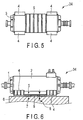
FIG. 5 is a bottom view showing another example of the bottom structure of the electric generator in the same embodiment; -
FIG. 6 is a side view for description of one example of a maintenance method for the electric generator according to the same embodiment; -
FIG. 7A and FIG. 7B are a side view and a bottom view showing a structure of a carrier device used in the same embodiment (where carriers of an air float type are adopted); -
FIG. 8 is a sectional view for description of an operation principle of the air float-type carriers used in the same embodiment; -
FIG. 9 is a top view for description of one example of the maintenance method for the electric generator according to the same embodiment; -
FIG. 10 is a front view for description of one example of the maintenance method for the electric generator according to the same embodiment; -
FIG. 11 is a front view for description of another example of the maintenance method for the electric generator according to the same embodiment; -
FIG. 12 is a sectional view showing one example of a structure of a carrier device guide used in the same embodiment; -
FIG. 13A and FIG. 13B are a side view and a top view showing a modification example of a structure of a foundation pedestal according to the same embodiment; -
FIG. 14A and FIG. 14B are a side view and a top view showing a modification example of the structure of the electric generator according to the same embodiment; -
FIG. 15 is a side view for description of a modification example of the maintenance method for the electric generator according to the same embodiment; -
FIG. 16 is a side view showing a modification example of the carrier device (carrier device of the combination of an air-pressure or water-pressure or oil-pressure lift-up mechanism and a dolly with rollers) used in the same embodiment; -
FIG. 17 is a side view showing another modification example of the carrier device (carrier device of the combination of an air-pressure or water-pressure or oil-pressure lift-up mechanism and rollers) used in the same embodiment; and -
FIG. 18 is a top view showing another modification example of the maintenance method for the electric generator according to the same embodiment. - Hereinafter, embodiments will be described with reference to the drawings.
- First, a shafting structure of a plant including an electric generator as an inspection target will be described.
-
FIG. 1 is a side view showing the shafting structure of a single-shaft type combined cycle power plant (combined-cycle power plant) adopting an electric generator driven at both ends according to one embodiment. - This plant is a combined-cycle power plant which drives an electric generator by a gas turbine and a steam turbine, wherein a
gas turbine 32, and a medium-to-highpressure steam turbine 36 and a lowpressure steam turbine 37 are disposed at the respective ends of anelectric generator 34, connected to each other via anintermediate shaft 33, aclutch 35, or the like, and linearly arranged on one axis as shown inFIG. 1 . Also, thegas turbine 32, the medium-to-highpressure steam turbine 36, the lowpressure steam turbine 37, and theelectric generator 34 are each installed onfoundation pedestals FIG. 1 . - Note that, in the following descriptions, the direction that is perpendicular and horizontal to the rotational axis of the electric generator will be called a "lateral direction".
-
FIG. 2 shows the structure of the electric generator according to this embodiment. - Generally, there are various forms for an electric generator to take, regarding the extracting direction of a terminal for extracting generated electric power, the arrangement of a cooler, the distance (center height) from the level of a foundation pedestal for installation of leg plates to the center of the axis of a rotor, and so on. In this embodiment, since the
electric generator 34 is moved in the lateral direction only with a slight uplift, it is a prerequisite to have a structure that does not cause the main structure of theelectric generator 34, such as aterminal 3, a cooler, and a frame, to interfere with the foundation pedestal during the movement in the lateral direction.FIG. 2 is drawn as one example of theelectric generator 34 that satisfies such a prerequisite, and the extracting direction of theterminal 3 is the area above the electric generator. - The
electric generator 34 is placed on thefoundation pedestal 6 usingleg plates 4 arranged at four corners, and secured by means of foundation bolts and key structures (omitted in the figures). Abottom plane 5 of theelectric generator 34, which is surrounded by theleg plates 4 at the four corners of theelectric generator 34, is at a position higher than the bottom face of theleg plates 4 and forms agap 8 between it and afloor face 7 of the foundation pedestal when theelectric generator 34 is viewed from the lateral direction. -
FIGS. 3 to 5 show examples of thebottom plane 5 of theelectric generator 34 when viewed from below. - The
bottom plane 5 of the electric generator is for evenly transferring the electric generator's own weight to a carrier device (described later). Thus, as shown by hatched lines inFIGS. 3 to 5 , thebottom plane 5 may be formed with a flat plate structure or as non-continuous structural faces in a grid pattern or a shelf plate pattern. - When conducting maintenance with such structures, a
carrier device 9 is inserted from the side into thegap 8 formed between thebottom plane 5 of the electric generator and thefloor face 7 of the foundation pedestal as shown inFIG. 6 . Thecarrier device 9 is a device capable of lifting up and horizontally moving theelectric generator 34. Thecarrier device 9 shown inFIG. 6 is an example of the carrier device in which carriers of an air float type are adopted. -
FIG. 7A and FIG. 7B show one example of the carrier device adopting air float-type carriers.FIG. 7A is a side view andFIG. 7B is a bottom view (view seen from the direction of arrow A that is in the middle ofFIG. 7A ). Also,FIG. 8 shows an operation principle of the air float-type carriers. Note that the arrows inFIG. 8 represent flows of compressed air. - The
carrier device 9 shown inFIG. 6 has a structure in which a plurality of air float-type carriers 22 are fixed under a load-receivingplate 21 as shown inFIG. 7A and FIG. 7B , and which includescasters 26 that contact the ground during the non-actuation of compressed air. - The air float-
type carrier 22 includes mainly abase 23 and abag 24, and lifts up the load loaded uponbase 23 using the air pressure in the bag created by supplying compressed air from anair supply port 25 to the inside of thebag 24. At this time, a thin film of air is formed between thebag 24 and afloor face 27, providing an advantage that a frictional force during the carriage is very small. There is also an advantage that the height of thecarrier device 9 can be lowered. - The
gap 8 formed between thebottom plane 5 of the electric generator and thefloor face 7 of the foundation pedestal is larger than the height of thecarrier device 9 during the non-actuation of compressed air by thecarrier device 9. This allows easy insertion of thecarrier device 9 into thegap 8 by means of thecasters 26 attached to thecarrier device 9, without an operation of jacking up theelectric generator 34. - Note that both ends of the rotor axis of the
electric generator 34 should be disconnected from other rotor axes in advance, and structural elements of the electric generator should be disconnected from structural elements of the foundation in advance. Also, the pipe arrangement of the electric generator, structural elements of the foundation, etc., that would interfere with theelectric generator 34 at the lateral movement should be disassembled. - Additionally, the piping of the electric generator should be formed into a structure that can be easily disassembled in order to avoid interference with the lateral movement; for example, a flange connection at the same level of the
floor face 7 of the foundation pedestal may be adopted, or a flanged short pipe may be provided at the level of thefloor face 7 of the foundation pedestal. For also the structural elements of the foundation, such as a foundation bolt, a stud structure protruding upward beyond thefloor face 7 of the foundation pedestal should be eliminated and a foundation bolt having a tap on the side of thefoundation pedestal 6 and being screwed from above theleg plates 4 may be adopted, and the members that would interfere with theelectric generator 34 during the lateral movement, such as an excitation bus bar standing from below thefoundation pedestal 6, should be formed into a structure that can be easily disassembled. - Next, air pressure is actuated for the
carrier device 9 to lift up theelectric generator 34 and to bring theleg plates 4 into a state of floating above thefoundation pedestal 6. - Thereafter, the
electric generator 34 is moved in the lateral direction over thefloor face 7 of the foundation pedestal by thecarrier device 9 as shown inFIG. 9 . Two examples of the method for the lateral movement of theelectric generator 34 are shown inFIG. 10 and FIG. 11. FIG. 10 shows an example in which acarrier drive device 10 associated with thecarrier device 9 is adopted.FIG. 11 shows an example in which achain block 12 andwire 11 are adopted between theelectric generator 34 and ananchor 13 of the foundation pedestal, as the motive power for the lateral movement. Other methods such as one using a winch or a crane may also be taken. - At the lateral movement, providing a
movement guide 14 for the carrier device as shown inFIG. 12 or a stopper would improve the workability and safety. This movement guide 14 or stopper may be provided on the floor face of the foundation pedestal on a permanent basis, or provided only for the work time by means of fastening, etc. - After the lateral movement to the position where a
rotor 1 can be pulled out without interfering with other equipment, theelectric generator 34 is lowered by discharging the air pressure of thecarrier device 9 and is placed on thefoundation pedestal 6 via theleg plates 4. At this position, disassembly of theelectric generator 34 and maintenance operations including taking out the rotor are conducted. - The respective steps of the maintenance operations of the
electric generator 34 described above are summarized as follows: - An axis disconnection step to disconnect the rotary machines at the respective axial ends of the
electric generator 34; - A foundation disconnection step to disconnect the
foundation pedestal 6 for theelectric generator 34 from theleg plates 4; - A disassembly step to disassemble, on the side of the
electric generator 34 and the side of thefoundation pedestal 6, structural elements that would cause interference between theelectric generator 34 and thefoundation pedestal 6 during the axially perpendicular movement of theelectric generator 34; - A carrier device insertion step to insert the
carrier device 9 into thegap 8; - A carriage step to lift up the
electric generator 34 by the actuation of thecarrier device 9 and laterally move theelectric generator 34 over thefloor face 7 of the foundation pedestal to a predetermined position; and - An electric generator placement step to place the
electric generator 34 at the predetermined position on thefoundation pedestal 6 via theleg plates 4. - After completing the maintenance operations for the
electric generator 34, theelectric generator 34 can be returned to its original position by carrying out the respective steps described as the pre-maintenance steps above in a reverse manner. In this instance, the pressure for thecarrier device 9 is actuated again for the uplift and the lateral movement of theelectric generator 34. After theelectric generator 34 is returned to the given installation position, the pressure of thecarrier device 9 is discharged, and theelectric generator 34 is installed at the given position on thefoundation pedestal 6 via theleg plates 4 and connected to the rotary machines at the respective axial ends. - For this re-installation of the
electric generator 34, alignment between the rotor axes to be connected and the respective ends of theelectric generator 34 needs to be adjusted. In this task, vertical adjustment is performed by varying the thickness of shims inserted under theleg plates 4, and the horizontal position of theelectric generator 34 is finely adjusted. In any case, however, jacking up theelectric generator 34 would be required. In the embodiment, the uplift function of thecarrier device 9 may also be utilized for this work, and thus, theelectric generator 34 can be installed while performing the alignment adjustment without a changeover after the lateral movement of theelectric generator 34. In other words, thecarrier device 9 itself can be utilized as a jacking device for theelectric generator 34 for the alignment adjustment task, so the necessity of setting up a new jacking device can be eliminated and the efficiency in re-installation operations can be achieved. - According to this embodiment as above, preparation for the movement of the electric generator is completed only by inserting the
carrier device 9 into thegap 8 formed between theelectric generator 34 and thefoundation pedestal 6, without lifting up (jacking up) theelectric generator 34, and theelectric generator 34 can be easily moved. Since a temporary crane or a work cradle for lifting up theelectric generator 34, or installation work for the temporary equipment for the lateral movement of theelectric generator 34 is not required, the maintenance costs and work time can be reduced. Moreover, with the smaller amount of uplift of theelectric generator 34, operational safety is improved, too. Also, the weight of theelectric generator 34 during carriage is received over a wide area of thefloor face 7 of the foundation pedestal, so the load on thefoundation pedestal 6 can be mitigated, also contributing to the reduction in basic costs during the construction. - Next, a modification example 1 of the above embodiment will be described with reference to
FIG. 13A and FIG. 13B . -
FIG. 13A and FIG. 13B are a side view and a top view mainly showing the modification example of the structure of thefoundation pedestal 6. - In the embodiment described above, the
gap 8 between thebottom plane 5 of the electric generator and thefloor face 7 of the foundation pedestal is provided by forming thebottom plane 5 of the electric generator to be higher than the bottom face of theleg plates 4. In contrast, in the modification example 1 shown inFIG. 13A and FIG. 13B , thegap 8 is provided by forming afloor face 15 of the foundation pedestal, located at the corresponding portion, to be lower than thefloor face 7 of the foundation pedestal where theleg plates 4 are placed. That is, the floor face of the foundation pedestal at the position facing thebottom plane 5 of the electric generator is made lower than the floor face of the foundation pedestal for the placement of theleg plates 4. - Also, this
low floor face 15 of the foundation pedestal is formed as the underside of agroove 16 having a width in the axial direction of the electric generator which is equal to or greater than the width of thecarrier device 9, and having a length in the axially perpendicular direction of the electric generator which assumes the movement range of theelectric generator 34 and the size, etc., of a drive mechanism associated with the carrier device. - When conducting maintenance with such a structure, the
carrier device 9 is positioned within thegroove 16 and inserted below thebottom plane 5 of theelectric generator 34, and then theelectric generator 34 is lifted up and moved in the lateral direction to a predetermined position by thecarrier device 9 in thegroove 16. - According to this modification example, the height of the center of the rotational axis of the
electric generator 34 from thefloor face 7 of the foundation pedestal (so-called center height) can be made lower than in the above-described embodiment by the amount of the gap. Also, since the side faces of thegroove 16 may serve as a movement guide or a stopper for the movement of the carrier device, the need to provide a separate movement guide or stopper can be eliminated. Together, as the movement face for the carrier device is defined, there is also an advantage that a smooth floor face required for the carrier device can be easily formed and maintained. - Next, a modification example 2 of the above embodiment will be described with reference to
FIG. 14A and FIG. 14B . -
FIG. 14A and FIG. 14B are a side view and a top view mainly showing the modification example of the structure of theelectric generator 34. - In the first embodiment described above, the load capacity of the
carrier device 9 depends on the surface area of thebottom plane 5 of the electric generator, so if the electric generator has a large weight for the surface area of thebottom plane 5 of the electric generator, thecarrier device 9 would lack a sufficient load capacity. In such an instance, a load-receivingextension rack 17 for extending the area of thebottom plane 5 of the electric generator in the axially perpendicular direction of the electric generator (constituting a plane flush with thebottom plane 5 of the electric generator) is added to the side face of thestator 2 of the electric generator, as shown inFIG. 14A and FIG. 14B . - The load-receiving
extension rack 17 may be formed integrally with thestator 2 of the electric generator or as a separate member attached by means of fastening, etc., to thestator 2 of the electric generator. - According to this modification example, providing the load-receiving
extension rack 17 can suitably extend the area of thebottom plane 5 of the electric generator. Therefore, the load restriction of thecarrier device 9 can be eliminated and the design margin of the carrier device can be increased. Together, the weight of the applicableelectric generator 34 can be increased. - Next, a modification example 3 of the above embodiment will be described with reference to
FIG. 15 . -
FIG. 15 is a side view showing the modification example of the maintenance method for theelectric generator 34. - In the first embodiment described above, when the
electric generator 34 is laterally moved, thecarrier device 9 supports theelectric generator 34. Depending on a structure of theelectric generator 34 or a form of the movement, acentral axis 18 of the electric generator which corresponds to the center of gravity of theelectric generator 34 may shift from acentral axis 19 of the carrier device which corresponds to the center position (load-receiving center) of thecarrier device 9. In such an instance, an uneven load may be applied to thecarrier device 9 and the intended performance might not be achieved. - Accordingly, it is effective to approximate the
central axis 19 of the carrier device to thecentral axis 18 of the electric generator by adjusting the axial position of thecarrier device 9; however, dimensional constraints on thecarrier device 9, theelectric generator 34, or the foundation may not allow a sufficient adjustment. To deal with this, it is possible to adjust the position of thecentral axis 18 of the electric generator by disassembling part of the components of theelectric generator 34 to reduce the load before operating thecarrier device 9, but as another method, it is also possible to add anecessary counter weight 20 to the electric generator as shown inFIG. 15 to approximate thecentral axis 18 of the electric generator to thecentral axis 19 of the carrier device and equally distribute the load onto the carrier device. - According to this modification example, when the center of gravity of the
electric generator 34 and the load-receiving center of thecarrier device 9 are deviated beyond a tolerable value, thecentral axis 18 of the electric generator and thecentral axis 19 of the carrier device can be approximated to each other by adjusting the center of gravity of theelectric generator 34 through the addition of thecounter weight 20 to one end of theelectric generator 34 or disassembly of part of the structure of the electric generator before the carriage operation. Therefore, the load on thecarrier device 9 can be evenly distributed. - Next, a modification example 4 of the above embodiment will be described with reference to
FIG. 16 and FIG. 17 . -
FIG. 16 is a side view showing a modification example of the carrier device 9 (carrier device of the combination of an air-pressure or water-pressure or oil-pressure lift-up mechanism and a dolly with rollers). Also,FIG. 17 is a side view showing a modification example of the carrier device 9 (carrier device of the combination of an air-pressure or water-pressure or oil-pressure lift-up mechanism and rollers). - As a carrier device for conducting maintenance operations, a
carrier device 9A having an air-pressure or water-pressure or oil-pressure jack 28, and having adolly 29 with rollers on which thejack 28 is mounted as shown inFIG. 16 , or acarrier device 9B having rollers 31 on whichjack 28 and ajack seating 30 for attachment of thejack 28 are also mounted as shown inFIG. 17 may be adopted, as well as thecarrier device 9 using the air float-type carriers 22 as shown inFIG. 8 for the above first embodiment. - As described above, the air float-
type carriers 22 cause the device to float due to a thin film of air, producing a very small frictional resistance during the lateral movement and providing the advantages of simplifying the drive mechanism and changeover for the lateral movement, and reducing the dimensions in the height direction as compared to other modes. However, the air float-type carriers 22 allow a relatively small load capacity. On the other hand, while the dimension in the height direction is increased, the modes to use a jack as shown inFIG. 16 and FIG. 17 can increase the load capacity by adopting, in particular, a pressure medium using water pressure or oil pressure. - Next, a modification example 5 of the above embodiment will be described with reference to
FIG. 18 . -
FIG. 18 is a top view showing the modification example of the maintenance operations for theelectric generator 34. - The above embodiment shows an example in which maintenance and inspection are conducted upon moving the
electric generator 34 by thecarrier device 9 in the lateral direction over thefloor face 7 of the foundation pedestal as shown inFIG. 9 . The maintenance and inspection for theelectric generator 34 may be conducted not only upon the lateral movement, but also upon horizontal rotation as shown inFIG. 18 whereby therotor 1 is pulled out and therotor 1 and thestator 2 are subjected to internal inspection. - Note that the steps for the maintenance operations for the
electric generator 34 in this modification example are the same as the steps in the above embodiment except the step to horizontally rotate theelectric generator 34. - According to this modification example, the method of horizontally rotating the
electric generator 34 can reduce the movement range of theelectric generator 34. Therefore, the required sizes of the foundation pedestal and thefloor face 7 of the foundation pedestal can also be reduced, contributing to the reduction in basic costs during the construction. - While certain embodiments have been described, these embodiments have been presented by way of example only, and are not intended to limit the scope of the inventions. Indeed, the novel embodiments described herein may be embodied in a variety of other forms; furthermore, various omissions, substitutions and changes in the form of the embodiments described herein may be made. The accompanying claims and their equivalents are intended to cover such forms or modifications as would fall within the scope of the inventions.
Claims (22)
- A maintenance method for an electric generator (34) applied to a power plant in which both axial ends of the electric generator (34) are connected to respective rotary machines, the maintenance method characterized by comprising:providing the electric generator (34) with leg plates (4) for placing the electric generator (34) on a floor face (7) of a foundation pedestal (6), forming a bottom portion of the electric generator (34) to have a bottom plane (5) capable of supporting a weight of the electric generator (34), and forming a gap (8) between the bottom plane (5) of the electric generator (34) and an opposing floor face (7) of the foundation pedestal (6) such that a carrier device (9) capable of lifting up and horizontally moving the electric generator (34) can be inserted into the gap (8) while the electric generator (34) is placed on the floor face (7) of the foundation pedestal (6) via the leg plates (4); andproviding the carrier device (9) in the gap (8), and lifting up and horizontally moving the electric generator (34) by the carrier device (9), and thereafter doing maintenance of the electric generator (34).
- The maintenance method according to claim 1,
wherein part or whole of the gap (8) is formed by forming the bottom plane (5) of the electric generator (34) to be higher than a bottom face of the leg plates (4). - The maintenance method according to claim 1,
wherein part or whole of the gap (8) is formed by forming the floor face (7) of the foundation pedestal (6) which faces the bottom plane (5) of the electric generator (34) to be lower than the floor face (7) of the foundation pedestal (6) where the leg plates (4) are disposed. - The maintenance method according to claim 3, further comprising forming a groove (16) at the floor face (7) of the foundation pedestal (6) which faces the bottom plane (5) of the electric generator (34), the groove having a width equal to or greater than a width of the carrier device (9) in the axial direction of the electric generator (34).
- The maintenance method according to claim 1, further comprising forming the electric generator (34) not to have a structure which interferes with the foundation pedestal (6) during the horizontal movement of the electric generator (34), or forming the electric generator (34) to have a component which interferes with the foundation pedestal (6) to be in an easily detachable structure.
- The maintenance method according to claim 1, further comprising forming the foundation pedestal (6) not to have a structure which interferes with the electric generator (34) during the horizontal movement of the electric generator (34), or forming the foundation pedestal (6) to have a component which interferes with the electric generator (34) to be in an easily detachable structure.
- The maintenance method according to claim 1, further comprising providing a load-receiving extension rack (17) to a side face of the electric generator (34), the load-receiving extension rack (17) extending an area of the bottom plane (5) of the electric generator (34) in an axially perpendicular direction of the electric generator (34).
- The maintenance method according to claim 1, further comprising: an axis disconnection step to disconnect the rotary machines at the respective axial ends of the electric generator (34); a foundation disconnection step to disconnect the leg plates (4) from the foundation pedestal (6) for the electric generator (34); a disassembly step to disassemble, on a side of the electric generator (34) and a side of the foundation pedestal (6), structural elements which cause interference between the electric generator (34) and the foundation pedestal (6) during the horizontal movement of the electric generator (34); a carrier device (9) insertion step to insert the carrier device (9) into the gap (8); a carriage step to lift up the electric generator (34) by actuation of the carrier device (9) and horizontally move the electric generator (34) over the floor face (7) of the foundation pedestal (6) to a predetermined position; and an electric generator (34) placement step to place the electric generator (34) at the predetermined position on the foundation pedestal (6) via the leg plates (4).
- The maintenance method according to claim 1, further comprising forming the carrier device (9) to have an air-float type carrier (22) capable of using air pressure to carry an item via an air film, and have a caster (26) to rest upon during non-actuation of air pressure.
- The maintenance method according to claim 1, further comprising forming the carrier device (9) to have an air-pressure or water-pressure or oil-pressure jack (28), and have a dolly (29) with rollers on which the jack (28) is mounted.
- The maintenance method according to claim 1, further comprising forming the carrier device (9) to have an air-pressure or water-pressure or oil-pressure jack (28), and have rollers (31) arranged under a seating (30) for attachment of the jack (28).
- The maintenance method according to claim 1, further comprising providing a movement guide (14) or a stopper to limit a movement range of the carrier device (9) during the horizontal movement of the electric generator (34) by the carrier device (9).
- The maintenance method according to claim 1, further comprising returning the electric generator (34) to an original position by performing the respective steps in a reverse manner after maintenance of the electric generator (34), and adjusting alignment of the electric generator (34) to the rotary machines at the respective axial ends using an uplift function of the carrier device (9).
- The maintenance method according to claim 8, further comprising adding a counter weight to one end of the electric generator (34) or disassembling part of the electric generator (34) before the movement of the electric generator (34) by the carrier device (9), so as to reduce a shift between a center of gravity of the electric generator (34) and a load-receiving center of the carrier device (9).
- An electric generator (34) of which both axial ends are connected to respective rotary machines, the electric generator (34) characterized by comprising:leg plates (4) for placing the electric generator (34) on a floor face (7) of a foundation pedestal (6); anda bottom plane (5) capable of supporting a weight of the electric generator (34) at a bottom portion;wherein a gap (8) is formed between the bottom plane (5) of the electric generator (34) and an opposing floor face (7) of the foundation pedestal (6) such that a carrier device (9) capable of lifting up and horizontally moving the electric generator (34) can be inserted into the gap (8) while the electric generator (34) is placed on the floor face (7) of the foundation pedestal (6) via the leg plates (4).
- The electric generator (34) according to claim 15, wherein part or whole of the gap (8) is formed by forming the bottom plane (5) of the electric generator (34) to be higher than a bottom face of the leg plates (4).
- The electric generator (34) according to claim 15, wherein a structure to interfere with the foundation pedestal (6) is absent during the horizontal movement of the electric generator (34), or a component which interferes with the foundation pedestal (6) is formed to be in an easily detachable structure.
- The electric generator (34) according to claim 15, further comprising a load-receiving extension rack (17) to extend an area of the bottom plane (5) of the electric generator (34) in an axially perpendicular direction of the electric generator (34).
- A foundation pedestal (6) for an electric generator (34) of which both axial ends are connected to respective rotary machines, the foundation pedestal (6) characterized by comprising:a floor face (7) for placing the electric generator (34),wherein a gap (8) is formed between a bottom plane (5) of the electric generator (34) and the floor face (7) of the foundation pedestal (6) which faces the bottom plane (5) of the electric generator (34) such that a carrier device (9) capable of lifting up and horizontally moving the electric generator (34) can be inserted into the gap (8) while the electric generator (34) is placed on the floor face (7) of the foundation pedestal (6) via leg plates (4).
- The foundation pedestal (6) according to claim 19, wherein part or whole of the gap (8) is formed by forming the floor face (7) of the foundation pedestal (6) which faces the bottom plane (5) of the electric generator (34) to be lower than the floor face (7) of the foundation pedestal (6) where the leg plates (4) are disposed.
- The foundation pedestal (6) according to claim 19, wherein a groove (16) is formed at the floor face (7) of the foundation pedestal (6) which faces the bottom plane (5) of the electric generator (34), the groove having a width equal to or greater than a width of the carrier device (9) in a horizontal direction in which the electric generator (34) moves.
- The foundation pedestal (6) according to claim 19, wherein a structure which interferes with the electric generator (34) is absent during the horizontal movement of the electric generator (34), or a component which interferes with the electric generator (34) is formed to be in an easily detachable structure.
Applications Claiming Priority (1)
| Application Number | Priority Date | Filing Date | Title |
|---|---|---|---|
| JP2016037702A JP2017158246A (en) | 2016-02-29 | 2016-02-29 | Generator, foundation base for generator, and maintenance method for generator |
Publications (2)
| Publication Number | Publication Date |
|---|---|
| EP3211766A1 true EP3211766A1 (en) | 2017-08-30 |
| EP3211766B1 EP3211766B1 (en) | 2019-03-27 |
Family
ID=58412841
Family Applications (1)
| Application Number | Title | Priority Date | Filing Date |
|---|---|---|---|
| EP17158240.6A Active EP3211766B1 (en) | 2016-02-29 | 2017-02-27 | Electric generator, foundation pedestal for electric generator and maintenance method for electric generator |
Country Status (5)
| Country | Link |
|---|---|
| US (1) | US20170250593A1 (en) |
| EP (1) | EP3211766B1 (en) |
| JP (1) | JP2017158246A (en) |
| KR (1) | KR20170101786A (en) |
| CN (1) | CN107134898A (en) |
Cited By (42)
| Publication number | Priority date | Publication date | Assignee | Title |
|---|---|---|---|---|
| CN109217527A (en) * | 2018-11-02 | 2019-01-15 | 徐州惠博机电科技有限公司 | A kind of motor with elastic easily assembling bracket |
| WO2020162940A1 (en) * | 2019-02-07 | 2020-08-13 | Siemens Energy, Inc. | Foundation for a generator |
| US10815764B1 (en) | 2019-09-13 | 2020-10-27 | Bj Energy Solutions, Llc | Methods and systems for operating a fleet of pumps |
| US10895202B1 (en) | 2019-09-13 | 2021-01-19 | Bj Energy Solutions, Llc | Direct drive unit removal system and associated methods |
| US10954770B1 (en) | 2020-06-09 | 2021-03-23 | Bj Energy Solutions, Llc | Systems and methods for exchanging fracturing components of a hydraulic fracturing unit |
| US10961908B1 (en) | 2020-06-05 | 2021-03-30 | Bj Energy Solutions, Llc | Systems and methods to enhance intake air flow to a gas turbine engine of a hydraulic fracturing unit |
| US10968837B1 (en) | 2020-05-14 | 2021-04-06 | Bj Energy Solutions, Llc | Systems and methods utilizing turbine compressor discharge for hydrostatic manifold purge |
| US10989180B2 (en) | 2019-09-13 | 2021-04-27 | Bj Energy Solutions, Llc | Power sources and transmission networks for auxiliary equipment onboard hydraulic fracturing units and associated methods |
| US11002189B2 (en) | 2019-09-13 | 2021-05-11 | Bj Energy Solutions, Llc | Mobile gas turbine inlet air conditioning system and associated methods |
| US11015594B2 (en) | 2019-09-13 | 2021-05-25 | Bj Energy Solutions, Llc | Systems and method for use of single mass flywheel alongside torsional vibration damper assembly for single acting reciprocating pump |
| US11015536B2 (en) | 2019-09-13 | 2021-05-25 | Bj Energy Solutions, Llc | Methods and systems for supplying fuel to gas turbine engines |
| US11022526B1 (en) | 2020-06-09 | 2021-06-01 | Bj Energy Solutions, Llc | Systems and methods for monitoring a condition of a fracturing component section of a hydraulic fracturing unit |
| US11028677B1 (en) | 2020-06-22 | 2021-06-08 | Bj Energy Solutions, Llc | Stage profiles for operations of hydraulic systems and associated methods |
| US11063491B2 (en) | 2018-11-19 | 2021-07-13 | General Electric Company | Generator mounting adaptor |
| US11066915B1 (en) | 2020-06-09 | 2021-07-20 | Bj Energy Solutions, Llc | Methods for detection and mitigation of well screen out |
| US11109508B1 (en) | 2020-06-05 | 2021-08-31 | Bj Energy Solutions, Llc | Enclosure assembly for enhanced cooling of direct drive unit and related methods |
| US11125066B1 (en) | 2020-06-22 | 2021-09-21 | Bj Energy Solutions, Llc | Systems and methods to operate a dual-shaft gas turbine engine for hydraulic fracturing |
| US11149533B1 (en) | 2020-06-24 | 2021-10-19 | Bj Energy Solutions, Llc | Systems to monitor, detect, and/or intervene relative to cavitation and pulsation events during a hydraulic fracturing operation |
| US11193360B1 (en) | 2020-07-17 | 2021-12-07 | Bj Energy Solutions, Llc | Methods, systems, and devices to enhance fracturing fluid delivery to subsurface formations during high-pressure fracturing operations |
| US11208880B2 (en) | 2020-05-28 | 2021-12-28 | Bj Energy Solutions, Llc | Bi-fuel reciprocating engine to power direct drive turbine fracturing pumps onboard auxiliary systems and related methods |
| US11208953B1 (en) | 2020-06-05 | 2021-12-28 | Bj Energy Solutions, Llc | Systems and methods to enhance intake air flow to a gas turbine engine of a hydraulic fracturing unit |
| US11220895B1 (en) | 2020-06-24 | 2022-01-11 | Bj Energy Solutions, Llc | Automated diagnostics of electronic instrumentation in a system for fracturing a well and associated methods |
| US11236739B2 (en) | 2019-09-13 | 2022-02-01 | Bj Energy Solutions, Llc | Power sources and transmission networks for auxiliary equipment onboard hydraulic fracturing units and associated methods |
| US11268346B2 (en) | 2019-09-13 | 2022-03-08 | Bj Energy Solutions, Llc | Fuel, communications, and power connection systems |
| US11408794B2 (en) | 2019-09-13 | 2022-08-09 | Bj Energy Solutions, Llc | Fuel, communications, and power connection systems and related methods |
| US11415125B2 (en) | 2020-06-23 | 2022-08-16 | Bj Energy Solutions, Llc | Systems for utilization of a hydraulic fracturing unit profile to operate hydraulic fracturing units |
| US11428165B2 (en) | 2020-05-15 | 2022-08-30 | Bj Energy Solutions, Llc | Onboard heater of auxiliary systems using exhaust gases and associated methods |
| US11473413B2 (en) | 2020-06-23 | 2022-10-18 | Bj Energy Solutions, Llc | Systems and methods to autonomously operate hydraulic fracturing units |
| US11560845B2 (en) | 2019-05-15 | 2023-01-24 | Bj Energy Solutions, Llc | Mobile gas turbine inlet air conditioning system and associated methods |
| US11624326B2 (en) | 2017-05-21 | 2023-04-11 | Bj Energy Solutions, Llc | Methods and systems for supplying fuel to gas turbine engines |
| US11635074B2 (en) | 2020-05-12 | 2023-04-25 | Bj Energy Solutions, Llc | Cover for fluid systems and related methods |
| US11639654B2 (en) | 2021-05-24 | 2023-05-02 | Bj Energy Solutions, Llc | Hydraulic fracturing pumps to enhance flow of fracturing fluid into wellheads and related methods |
| US11643915B2 (en) | 2020-06-09 | 2023-05-09 | Bj Energy Solutions, Llc | Drive equipment and methods for mobile fracturing transportation platforms |
| US11867118B2 (en) | 2019-09-13 | 2024-01-09 | Bj Energy Solutions, Llc | Methods and systems for supplying fuel to gas turbine engines |
| US11933153B2 (en) | 2020-06-22 | 2024-03-19 | Bj Energy Solutions, Llc | Systems and methods to operate hydraulic fracturing units using automatic flow rate and/or pressure control |
| US11939853B2 (en) | 2020-06-22 | 2024-03-26 | Bj Energy Solutions, Llc | Systems and methods providing a configurable staged rate increase function to operate hydraulic fracturing units |
| US12065968B2 (en) | 2019-09-13 | 2024-08-20 | BJ Energy Solutions, Inc. | Systems and methods for hydraulic fracturing |
| US12281964B2 (en) | 2019-09-13 | 2025-04-22 | Bj Energy Solutions, Llc | Fuel, communications, and power connection systems and related methods |
| US12338772B2 (en) | 2019-09-13 | 2025-06-24 | Bj Energy Solutions, Llc | Systems, assemblies, and methods to enhance intake air flow to a gas turbine engine of a hydraulic fracturing unit |
| US12378864B2 (en) | 2021-10-25 | 2025-08-05 | Bj Energy Solutions, Llc | Systems and methods to reduce acoustic resonance or disrupt standing wave formation in a fluid manifold of a high-pressure fracturing system |
| US12516632B2 (en) | 2019-09-13 | 2026-01-06 | Bj Energy Solutions, Llc | Turbine engine exhaust duct system and methods for noise dampening and attenuation |
| US12631102B2 (en) | 2024-07-18 | 2026-05-19 | Bj Energy Solutions, Llc | Systems and methods to autonomously operate hydraulic fracturing units |
Families Citing this family (8)
| Publication number | Priority date | Publication date | Assignee | Title |
|---|---|---|---|---|
| KR101895752B1 (en) * | 2018-03-20 | 2018-09-05 | 한창수 | Apparatus for repairing of electric generator |
| CN109660063B (en) * | 2019-03-05 | 2023-09-26 | 浙江晋一特种电机有限公司 | A vibration damping base for permanent magnet synchronous motor and its installation method |
| JP7126802B1 (en) * | 2020-10-30 | 2022-08-29 | 東芝三菱電機産業システム株式会社 | Conveyor |
| EP4514723B1 (en) * | 2022-04-29 | 2026-04-15 | Abb Schweiz Ag | Conveyor drive system |
| US20240141799A1 (en) * | 2022-11-02 | 2024-05-02 | Siemens Energy Global GmbH & Co. KG | Disassembly and reassembly of a generator rotor in a plant |
| CN116164151B (en) * | 2023-04-21 | 2023-07-18 | 东方电气集团东方电机有限公司 | Ball valve mounting structure and hydroelectric power generation system |
| KR20260014375A (en) * | 2024-07-23 | 2026-01-30 | 한국수력원자력 주식회사 | Apparatus and method for moving Emergency Diesel Generator in power plant |
| CN118646224B (en) * | 2024-08-19 | 2024-10-22 | 中信重工机械股份有限公司 | Construction method for modifying permanent magnet synchronous driving system of on-line elevator |
Citations (5)
| Publication number | Priority date | Publication date | Assignee | Title |
|---|---|---|---|---|
| JPS58163246A (en) * | 1982-03-19 | 1983-09-28 | Hitachi Ltd | How to pull out and disassemble the rotor of a rotating electrical machine |
| US5609018A (en) * | 1994-08-19 | 1997-03-11 | Abb Management Ag | Combined installation for gas and steam turbines |
| US20050150095A1 (en) * | 2004-01-08 | 2005-07-14 | General Electric Company | Methods of generator rotor removal in a combined-cycle stag application |
| US20120228974A1 (en) * | 2011-03-10 | 2012-09-13 | General Electric Company | Centerline generator support system and method of elevating a centerline generator from a support surface |
| WO2015064208A1 (en) * | 2013-10-30 | 2015-05-07 | 三菱日立パワーシステムズ株式会社 | Generator inspection method |
Family Cites Families (15)
| Publication number | Priority date | Publication date | Assignee | Title |
|---|---|---|---|---|
| JPS57106213U (en) * | 1980-12-19 | 1982-06-30 | ||
| JPS5997585U (en) * | 1982-12-22 | 1984-07-02 | 株式会社日立製作所 | Structure of rotating electrical machine |
| JPH076698Y2 (en) * | 1985-03-20 | 1995-02-15 | 株式会社明電舎 | Turbine generator |
| JPH0610217U (en) * | 1992-07-20 | 1994-02-08 | 鹿島建設株式会社 | Mobile device |
| JP3525260B2 (en) * | 1992-10-02 | 2004-05-10 | 山九株式会社 | Transfer device |
| JP3431852B2 (en) * | 1998-03-30 | 2003-07-28 | 豊田スチールセンター株式会社 | Heavy object transfer device and heavy object transfer method |
| JP2002187606A (en) * | 2000-12-25 | 2002-07-02 | Mitsubishi Heavy Ind Ltd | Carrying device for container and carrying method |
| JP2003120903A (en) * | 2001-10-10 | 2003-04-23 | Toshiba Corp | Exhaust heat recovery boiler and its transportation method |
| CN102624147B (en) * | 2011-01-26 | 2016-03-23 | 阿尔斯通技术有限公司 | Improve the method in power plant |
| CN102651588A (en) * | 2011-02-25 | 2012-08-29 | 上海宝钢设备检修有限公司 | Drawing method of gas turbine generator rotor in overhauling operation |
| ITFI20120114A1 (en) * | 2012-06-08 | 2013-12-09 | Nuovo Pignone Srl | "MODULAR GAS PLANT TURBINE WITH A HEAVY DUTY GAS TURBINE" |
| CN103633787A (en) * | 2012-08-29 | 2014-03-12 | 上海宝钢工业技术服务有限公司 | Reassembling method of disassembled and repaired turbonator |
| US10054253B2 (en) * | 2014-12-05 | 2018-08-21 | General Electric Company | System for laterally moving industrial machine |
| CN204578308U (en) * | 2015-05-12 | 2015-08-19 | 华电(北京)热电有限公司 | Transport trainset |
| CN105141076B (en) * | 2015-08-25 | 2018-01-23 | 内蒙古伊泰煤制油有限责任公司 | A kind of method of electrical machmary maintenance |
-
2016
- 2016-02-29 JP JP2016037702A patent/JP2017158246A/en active Pending
-
2017
- 2017-02-17 KR KR1020170021340A patent/KR20170101786A/en not_active Ceased
- 2017-02-23 CN CN201710099049.0A patent/CN107134898A/en active Pending
- 2017-02-27 EP EP17158240.6A patent/EP3211766B1/en active Active
- 2017-02-28 US US15/445,346 patent/US20170250593A1/en not_active Abandoned
Patent Citations (5)
| Publication number | Priority date | Publication date | Assignee | Title |
|---|---|---|---|---|
| JPS58163246A (en) * | 1982-03-19 | 1983-09-28 | Hitachi Ltd | How to pull out and disassemble the rotor of a rotating electrical machine |
| US5609018A (en) * | 1994-08-19 | 1997-03-11 | Abb Management Ag | Combined installation for gas and steam turbines |
| US20050150095A1 (en) * | 2004-01-08 | 2005-07-14 | General Electric Company | Methods of generator rotor removal in a combined-cycle stag application |
| US20120228974A1 (en) * | 2011-03-10 | 2012-09-13 | General Electric Company | Centerline generator support system and method of elevating a centerline generator from a support surface |
| WO2015064208A1 (en) * | 2013-10-30 | 2015-05-07 | 三菱日立パワーシステムズ株式会社 | Generator inspection method |
Non-Patent Citations (1)
| Title |
|---|
| ANONYMOUS: "Utilities - Air Caster", 25 January 2016 (2016-01-25), XP055391142, Retrieved from the Internet <URL:https://web.archive.org/web/20160125201910/http://www.aircaster.com/applications/utilities/> [retrieved on 20170714] * |
Cited By (160)
| Publication number | Priority date | Publication date | Assignee | Title |
|---|---|---|---|---|
| US11624326B2 (en) | 2017-05-21 | 2023-04-11 | Bj Energy Solutions, Llc | Methods and systems for supplying fuel to gas turbine engines |
| CN109217527A (en) * | 2018-11-02 | 2019-01-15 | 徐州惠博机电科技有限公司 | A kind of motor with elastic easily assembling bracket |
| US11063491B2 (en) | 2018-11-19 | 2021-07-13 | General Electric Company | Generator mounting adaptor |
| WO2020162940A1 (en) * | 2019-02-07 | 2020-08-13 | Siemens Energy, Inc. | Foundation for a generator |
| US12060688B2 (en) | 2019-02-07 | 2024-08-13 | Siemens Energy, Inc. | Foundation for a generator |
| US11560845B2 (en) | 2019-05-15 | 2023-01-24 | Bj Energy Solutions, Llc | Mobile gas turbine inlet air conditioning system and associated methods |
| US11473997B2 (en) | 2019-09-13 | 2022-10-18 | Bj Energy Solutions, Llc | Fuel, communications, and power connection systems and related methods |
| US11319878B2 (en) | 2019-09-13 | 2022-05-03 | Bj Energy Solutions, Llc | Direct drive unit removal system and associated methods |
| US11619122B2 (en) | 2019-09-13 | 2023-04-04 | Bj Energy Solutions, Llc | Methods and systems for operating a fleet of pumps |
| US10982596B1 (en) | 2019-09-13 | 2021-04-20 | Bj Energy Solutions, Llc | Direct drive unit removal system and associated methods |
| US10989180B2 (en) | 2019-09-13 | 2021-04-27 | Bj Energy Solutions, Llc | Power sources and transmission networks for auxiliary equipment onboard hydraulic fracturing units and associated methods |
| US11002189B2 (en) | 2019-09-13 | 2021-05-11 | Bj Energy Solutions, Llc | Mobile gas turbine inlet air conditioning system and associated methods |
| US11015594B2 (en) | 2019-09-13 | 2021-05-25 | Bj Energy Solutions, Llc | Systems and method for use of single mass flywheel alongside torsional vibration damper assembly for single acting reciprocating pump |
| US11015536B2 (en) | 2019-09-13 | 2021-05-25 | Bj Energy Solutions, Llc | Methods and systems for supplying fuel to gas turbine engines |
| US12510070B2 (en) | 2019-09-13 | 2025-12-30 | Bj Energy Solutions, Llc | Systems and method for use of single mass flywheel alongside torsional vibration damper assembly for single acting reciprocating pump |
| US12510028B2 (en) | 2019-09-13 | 2025-12-30 | Bj Energy Solutions, Llc | Direct drive unit removal system and associated methods |
| US12497879B2 (en) | 2019-09-13 | 2025-12-16 | Bj Energy Solutions, Llc | Power sources and transmission networks for auxiliary equipment onboard hydraulic fracturing units and associated methods |
| US11608725B2 (en) | 2019-09-13 | 2023-03-21 | Bj Energy Solutions, Llc | Methods and systems for operating a fleet of pumps |
| US11060455B1 (en) | 2019-09-13 | 2021-07-13 | Bj Energy Solutions, Llc | Mobile gas turbine inlet air conditioning system and associated methods |
| US12467348B2 (en) | 2019-09-13 | 2025-11-11 | Bj Energy Solutions, Llc | Methods and systems for operating a fleet of pumps |
| US11604113B2 (en) | 2019-09-13 | 2023-03-14 | Bj Energy Solutions, Llc | Fuel, communications, and power connection systems and related methods |
| US11092152B2 (en) | 2019-09-13 | 2021-08-17 | Bj Energy Solutions, Llc | Systems and method for use of single mass flywheel alongside torsional vibration damper assembly for single acting reciprocating pump |
| US10815764B1 (en) | 2019-09-13 | 2020-10-27 | Bj Energy Solutions, Llc | Methods and systems for operating a fleet of pumps |
| US11598263B2 (en) | 2019-09-13 | 2023-03-07 | Bj Energy Solutions, Llc | Mobile gas turbine inlet air conditioning system and associated methods |
| US11578660B1 (en) | 2019-09-13 | 2023-02-14 | Bj Energy Solutions, Llc | Direct drive unit removal system and associated methods |
| US12338772B2 (en) | 2019-09-13 | 2025-06-24 | Bj Energy Solutions, Llc | Systems, assemblies, and methods to enhance intake air flow to a gas turbine engine of a hydraulic fracturing unit |
| US11149726B1 (en) | 2019-09-13 | 2021-10-19 | Bj Energy Solutions, Llc | Systems and method for use of single mass flywheel alongside torsional vibration damper assembly for single acting reciprocating pump |
| US11156159B1 (en) | 2019-09-13 | 2021-10-26 | Bj Energy Solutions, Llc | Mobile gas turbine inlet air conditioning system and associated methods |
| US12281964B2 (en) | 2019-09-13 | 2025-04-22 | Bj Energy Solutions, Llc | Fuel, communications, and power connection systems and related methods |
| US12276577B2 (en) | 2019-09-13 | 2025-04-15 | Bj Energy Solutions, Llc | Fuel, communications, and power connection systems and related methods |
| US12092100B2 (en) | 2019-09-13 | 2024-09-17 | Bj Energy Solutions, Llc | Systems and method for use of single mass flywheel alongside torsional vibration damper assembly for single acting reciprocating pump |
| US11629584B2 (en) | 2019-09-13 | 2023-04-18 | Bj Energy Solutions, Llc | Power sources and transmission networks for auxiliary equipment onboard hydraulic fracturing units and associated methods |
| US12065968B2 (en) | 2019-09-13 | 2024-08-20 | BJ Energy Solutions, Inc. | Systems and methods for hydraulic fracturing |
| US10895202B1 (en) | 2019-09-13 | 2021-01-19 | Bj Energy Solutions, Llc | Direct drive unit removal system and associated methods |
| US12516632B2 (en) | 2019-09-13 | 2026-01-06 | Bj Energy Solutions, Llc | Turbine engine exhaust duct system and methods for noise dampening and attenuation |
| US11236739B2 (en) | 2019-09-13 | 2022-02-01 | Bj Energy Solutions, Llc | Power sources and transmission networks for auxiliary equipment onboard hydraulic fracturing units and associated methods |
| US12049808B2 (en) | 2019-09-13 | 2024-07-30 | Bj Energy Solutions, Llc | Methods and systems for operating a fleet of pumps |
| US11971028B2 (en) | 2019-09-13 | 2024-04-30 | Bj Energy Solutions, Llc | Systems and method for use of single mass flywheel alongside torsional vibration damper assembly for single acting reciprocating pump |
| US11555756B2 (en) | 2019-09-13 | 2023-01-17 | Bj Energy Solutions, Llc | Fuel, communications, and power connection systems and related methods |
| US10907459B1 (en) | 2019-09-13 | 2021-02-02 | Bj Energy Solutions, Llc | Methods and systems for operating a fleet of pumps |
| US11268346B2 (en) | 2019-09-13 | 2022-03-08 | Bj Energy Solutions, Llc | Fuel, communications, and power connection systems |
| US11530602B2 (en) | 2019-09-13 | 2022-12-20 | Bj Energy Solutions, Llc | Power sources and transmission networks for auxiliary equipment onboard hydraulic fracturing units and associated methods |
| US11280331B2 (en) | 2019-09-13 | 2022-03-22 | Bj Energy Solutions, Llc | Systems and method for use of single mass flywheel alongside torsional vibration damper assembly for single acting reciprocating pump |
| US11280266B2 (en) | 2019-09-13 | 2022-03-22 | Bj Energy Solutions, Llc | Mobile gas turbine inlet air conditioning system and associated methods |
| US11287350B2 (en) | 2019-09-13 | 2022-03-29 | Bj Energy Solutions, Llc | Fuel, communications, and power connection methods |
| US11655763B1 (en) | 2019-09-13 | 2023-05-23 | Bj Energy Solutions, Llc | Direct drive unit removal system and associated methods |
| US10961912B1 (en) | 2019-09-13 | 2021-03-30 | Bj Energy Solutions, Llc | Direct drive unit removal system and associated methods |
| US11512642B1 (en) | 2019-09-13 | 2022-11-29 | Bj Energy Solutions, Llc | Direct drive unit removal system and associated methods |
| US11649766B1 (en) | 2019-09-13 | 2023-05-16 | Bj Energy Solutions, Llc | Mobile gas turbine inlet air conditioning system and associated methods |
| US11867118B2 (en) | 2019-09-13 | 2024-01-09 | Bj Energy Solutions, Llc | Methods and systems for supplying fuel to gas turbine engines |
| US11859482B2 (en) | 2019-09-13 | 2024-01-02 | Bj Energy Solutions, Llc | Power sources and transmission networks for auxiliary equipment onboard hydraulic fracturing units and associated methods |
| US11346280B1 (en) | 2019-09-13 | 2022-05-31 | Bj Energy Solutions, Llc | Direct drive unit removal system and associated methods |
| US11719234B2 (en) | 2019-09-13 | 2023-08-08 | Bj Energy Solutions, Llc | Systems and method for use of single mass flywheel alongside torsional vibration damper assembly for single acting reciprocating pump |
| US11613980B2 (en) | 2019-09-13 | 2023-03-28 | Bj Energy Solutions, Llc | Methods and systems for operating a fleet of pumps |
| US11473503B1 (en) | 2019-09-13 | 2022-10-18 | Bj Energy Solutions, Llc | Direct drive unit removal system and associated methods |
| US11767791B2 (en) | 2019-09-13 | 2023-09-26 | Bj Energy Solutions, Llc | Mobile gas turbine inlet air conditioning system and associated methods |
| US11401865B1 (en) | 2019-09-13 | 2022-08-02 | Bj Energy Solutions, Llc | Direct drive unit removal system and associated methods |
| US11408794B2 (en) | 2019-09-13 | 2022-08-09 | Bj Energy Solutions, Llc | Fuel, communications, and power connection systems and related methods |
| US11761846B2 (en) | 2019-09-13 | 2023-09-19 | Bj Energy Solutions, Llc | Fuel, communications, and power connection systems and related methods |
| US11460368B2 (en) | 2019-09-13 | 2022-10-04 | Bj Energy Solutions, Llc | Fuel, communications, and power connection systems and related methods |
| US11725583B2 (en) | 2019-09-13 | 2023-08-15 | Bj Energy Solutions, Llc | Mobile gas turbine inlet air conditioning system and associated methods |
| US11708829B2 (en) | 2020-05-12 | 2023-07-25 | Bj Energy Solutions, Llc | Cover for fluid systems and related methods |
| US12404856B2 (en) | 2020-05-12 | 2025-09-02 | Bj Energy Solutions, Llc | Cover for fluid systems and related methods |
| US11635074B2 (en) | 2020-05-12 | 2023-04-25 | Bj Energy Solutions, Llc | Cover for fluid systems and related methods |
| US10968837B1 (en) | 2020-05-14 | 2021-04-06 | Bj Energy Solutions, Llc | Systems and methods utilizing turbine compressor discharge for hydrostatic manifold purge |
| US11898504B2 (en) | 2020-05-14 | 2024-02-13 | Bj Energy Solutions, Llc | Systems and methods utilizing turbine compressor discharge for hydrostatic manifold purge |
| US11624321B2 (en) | 2020-05-15 | 2023-04-11 | Bj Energy Solutions, Llc | Onboard heater of auxiliary systems using exhaust gases and associated methods |
| US11698028B2 (en) | 2020-05-15 | 2023-07-11 | Bj Energy Solutions, Llc | Onboard heater of auxiliary systems using exhaust gases and associated methods |
| US11434820B2 (en) | 2020-05-15 | 2022-09-06 | Bj Energy Solutions, Llc | Onboard heater of auxiliary systems using exhaust gases and associated methods |
| US11959419B2 (en) | 2020-05-15 | 2024-04-16 | Bj Energy Solutions, Llc | Onboard heater of auxiliary systems using exhaust gases and associated methods |
| US11428165B2 (en) | 2020-05-15 | 2022-08-30 | Bj Energy Solutions, Llc | Onboard heater of auxiliary systems using exhaust gases and associated methods |
| US11542868B2 (en) | 2020-05-15 | 2023-01-03 | Bj Energy Solutions, Llc | Onboard heater of auxiliary systems using exhaust gases and associated methods |
| US11365616B1 (en) | 2020-05-28 | 2022-06-21 | Bj Energy Solutions, Llc | Bi-fuel reciprocating engine to power direct drive turbine fracturing pumps onboard auxiliary systems and related methods |
| US11814940B2 (en) | 2020-05-28 | 2023-11-14 | Bj Energy Solutions Llc | Bi-fuel reciprocating engine to power direct drive turbine fracturing pumps onboard auxiliary systems and related methods |
| US11603745B2 (en) | 2020-05-28 | 2023-03-14 | Bj Energy Solutions, Llc | Bi-fuel reciprocating engine to power direct drive turbine fracturing pumps onboard auxiliary systems and related methods |
| US11313213B2 (en) | 2020-05-28 | 2022-04-26 | Bj Energy Solutions, Llc | Bi-fuel reciprocating engine to power direct drive turbine fracturing pumps onboard auxiliary systems and related methods |
| US11208880B2 (en) | 2020-05-28 | 2021-12-28 | Bj Energy Solutions, Llc | Bi-fuel reciprocating engine to power direct drive turbine fracturing pumps onboard auxiliary systems and related methods |
| US11723171B2 (en) | 2020-06-05 | 2023-08-08 | Bj Energy Solutions, Llc | Enclosure assembly for enhanced cooling of direct drive unit and related methods |
| US11208953B1 (en) | 2020-06-05 | 2021-12-28 | Bj Energy Solutions, Llc | Systems and methods to enhance intake air flow to a gas turbine engine of a hydraulic fracturing unit |
| US11378008B2 (en) | 2020-06-05 | 2022-07-05 | Bj Energy Solutions, Llc | Systems and methods to enhance intake air flow to a gas turbine engine of a hydraulic fracturing unit |
| US11129295B1 (en) | 2020-06-05 | 2021-09-21 | Bj Energy Solutions, Llc | Enclosure assembly for enhanced cooling of direct drive unit and related methods |
| US11746698B2 (en) | 2020-06-05 | 2023-09-05 | Bj Energy Solutions, Llc | Systems and methods to enhance intake air flow to a gas turbine engine of a hydraulic fracturing unit |
| US11598264B2 (en) | 2020-06-05 | 2023-03-07 | Bj Energy Solutions, Llc | Systems and methods to enhance intake air flow to a gas turbine engine of a hydraulic fracturing unit |
| US11109508B1 (en) | 2020-06-05 | 2021-08-31 | Bj Energy Solutions, Llc | Enclosure assembly for enhanced cooling of direct drive unit and related methods |
| US11891952B2 (en) | 2020-06-05 | 2024-02-06 | Bj Energy Solutions, Llc | Systems and methods to enhance intake air flow to a gas turbine engine of a hydraulic fracturing unit |
| US11627683B2 (en) | 2020-06-05 | 2023-04-11 | Bj Energy Solutions, Llc | Enclosure assembly for enhanced cooling of direct drive unit and related methods |
| US12408291B2 (en) | 2020-06-05 | 2025-09-02 | Bj Energy Solutions, Llc | Enclosure assembly for enhanced cooling of direct drive unit and related methods |
| US10961908B1 (en) | 2020-06-05 | 2021-03-30 | Bj Energy Solutions, Llc | Systems and methods to enhance intake air flow to a gas turbine engine of a hydraulic fracturing unit |
| US11300050B2 (en) | 2020-06-05 | 2022-04-12 | Bj Energy Solutions, Llc | Systems and methods to enhance intake air flow to a gas turbine engine of a hydraulic fracturing unit |
| US11261717B2 (en) | 2020-06-09 | 2022-03-01 | Bj Energy Solutions, Llc | Systems and methods for exchanging fracturing components of a hydraulic fracturing unit |
| US11066915B1 (en) | 2020-06-09 | 2021-07-20 | Bj Energy Solutions, Llc | Methods for detection and mitigation of well screen out |
| US11939854B2 (en) | 2020-06-09 | 2024-03-26 | Bj Energy Solutions, Llc | Methods for detection and mitigation of well screen out |
| US11208881B1 (en) | 2020-06-09 | 2021-12-28 | Bj Energy Solutions, Llc | Methods and systems for detection and mitigation of well screen out |
| US11319791B2 (en) | 2020-06-09 | 2022-05-03 | Bj Energy Solutions, Llc | Methods and systems for detection and mitigation of well screen out |
| US11629583B2 (en) | 2020-06-09 | 2023-04-18 | Bj Energy Solutions, Llc | Systems and methods for exchanging fracturing components of a hydraulic fracturing unit |
| US11867046B2 (en) | 2020-06-09 | 2024-01-09 | Bj Energy Solutions, Llc | Systems and methods for exchanging fracturing components of a hydraulic fracturing unit |
| US11566506B2 (en) | 2020-06-09 | 2023-01-31 | Bj Energy Solutions, Llc | Methods for detection and mitigation of well screen out |
| US11339638B1 (en) | 2020-06-09 | 2022-05-24 | Bj Energy Solutions, Llc | Systems and methods for exchanging fracturing components of a hydraulic fracturing unit |
| US10954770B1 (en) | 2020-06-09 | 2021-03-23 | Bj Energy Solutions, Llc | Systems and methods for exchanging fracturing components of a hydraulic fracturing unit |
| US11643915B2 (en) | 2020-06-09 | 2023-05-09 | Bj Energy Solutions, Llc | Drive equipment and methods for mobile fracturing transportation platforms |
| US11015423B1 (en) | 2020-06-09 | 2021-05-25 | Bj Energy Solutions, Llc | Systems and methods for exchanging fracturing components of a hydraulic fracturing unit |
| US12305495B2 (en) | 2020-06-09 | 2025-05-20 | Bj Energy Solutions, Llc | Systems and methods for exchanging fracturing components of a hydraulic fracturing unit |
| US11512570B2 (en) | 2020-06-09 | 2022-11-29 | Bj Energy Solutions, Llc | Systems and methods for exchanging fracturing components of a hydraulic fracturing unit |
| US12385379B2 (en) | 2020-06-09 | 2025-08-12 | Bj Energy Solutions, Llc | Methods for detection and mitigation of well screen out |
| US11022526B1 (en) | 2020-06-09 | 2021-06-01 | Bj Energy Solutions, Llc | Systems and methods for monitoring a condition of a fracturing component section of a hydraulic fracturing unit |
| US11085281B1 (en) | 2020-06-09 | 2021-08-10 | Bj Energy Solutions, Llc | Systems and methods for exchanging fracturing components of a hydraulic fracturing unit |
| US12286874B2 (en) | 2020-06-22 | 2025-04-29 | Bj Energy Solutions, Llc | Systems and methods to operate hydraulic fracturing units using automatic flow rate and/or pressure control |
| US11639655B2 (en) | 2020-06-22 | 2023-05-02 | Bj Energy Solutions, Llc | Systems and methods to operate a dual-shaft gas turbine engine for hydraulic fracturing |
| US11952878B2 (en) | 2020-06-22 | 2024-04-09 | Bj Energy Solutions, Llc | Stage profiles for operations of hydraulic systems and associated methods |
| US12584394B2 (en) | 2020-06-22 | 2026-03-24 | Bj Energy Solutions, Llc | Systems and methods to operate a dual-shaft gas turbine engine for hydraulic fracturing |
| US11939853B2 (en) | 2020-06-22 | 2024-03-26 | Bj Energy Solutions, Llc | Systems and methods providing a configurable staged rate increase function to operate hydraulic fracturing units |
| US11933153B2 (en) | 2020-06-22 | 2024-03-19 | Bj Energy Solutions, Llc | Systems and methods to operate hydraulic fracturing units using automatic flow rate and/or pressure control |
| US11732565B2 (en) | 2020-06-22 | 2023-08-22 | Bj Energy Solutions, Llc | Systems and methods to operate a dual-shaft gas turbine engine for hydraulic fracturing |
| US11125066B1 (en) | 2020-06-22 | 2021-09-21 | Bj Energy Solutions, Llc | Systems and methods to operate a dual-shaft gas turbine engine for hydraulic fracturing |
| US11598188B2 (en) | 2020-06-22 | 2023-03-07 | Bj Energy Solutions, Llc | Stage profiles for operations of hydraulic systems and associated methods |
| US11898429B2 (en) | 2020-06-22 | 2024-02-13 | Bj Energy Solutions, Llc | Systems and methods to operate a dual-shaft gas turbine engine for hydraulic fracturing |
| US11408263B2 (en) | 2020-06-22 | 2022-08-09 | Bj Energy Solutions, Llc | Systems and methods to operate a dual-shaft gas turbine engine for hydraulic fracturing |
| US12326075B2 (en) | 2020-06-22 | 2025-06-10 | Bj Energy Solutions, Llc | Stage profiles for operations of hydraulic systems and associated methods |
| US11208879B1 (en) | 2020-06-22 | 2021-12-28 | Bj Energy Solutions, Llc | Stage profiles for operations of hydraulic systems and associated methods |
| US11028677B1 (en) | 2020-06-22 | 2021-06-08 | Bj Energy Solutions, Llc | Stage profiles for operations of hydraulic systems and associated methods |
| US11236598B1 (en) | 2020-06-22 | 2022-02-01 | Bj Energy Solutions, Llc | Stage profiles for operations of hydraulic systems and associated methods |
| US11572774B2 (en) | 2020-06-22 | 2023-02-07 | Bj Energy Solutions, Llc | Systems and methods to operate a dual-shaft gas turbine engine for hydraulic fracturing |
| US11566505B2 (en) | 2020-06-23 | 2023-01-31 | Bj Energy Solutions, Llc | Systems and methods to autonomously operate hydraulic fracturing units |
| US11649820B2 (en) | 2020-06-23 | 2023-05-16 | Bj Energy Solutions, Llc | Systems and methods of utilization of a hydraulic fracturing unit profile to operate hydraulic fracturing units |
| US11661832B2 (en) | 2020-06-23 | 2023-05-30 | Bj Energy Solutions, Llc | Systems and methods to autonomously operate hydraulic fracturing units |
| US12065917B2 (en) | 2020-06-23 | 2024-08-20 | Bj Energy Solutions, Llc | Systems and methods to autonomously operate hydraulic fracturing units |
| US11415125B2 (en) | 2020-06-23 | 2022-08-16 | Bj Energy Solutions, Llc | Systems for utilization of a hydraulic fracturing unit profile to operate hydraulic fracturing units |
| US11428218B2 (en) | 2020-06-23 | 2022-08-30 | Bj Energy Solutions, Llc | Systems and methods of utilization of a hydraulic fracturing unit profile to operate hydraulic fracturing units |
| US11939974B2 (en) | 2020-06-23 | 2024-03-26 | Bj Energy Solutions, Llc | Systems and methods of utilization of a hydraulic fracturing unit profile to operate hydraulic fracturing units |
| US11466680B2 (en) | 2020-06-23 | 2022-10-11 | Bj Energy Solutions, Llc | Systems and methods of utilization of a hydraulic fracturing unit profile to operate hydraulic fracturing units |
| US11719085B1 (en) | 2020-06-23 | 2023-08-08 | Bj Energy Solutions, Llc | Systems and methods to autonomously operate hydraulic fracturing units |
| US11473413B2 (en) | 2020-06-23 | 2022-10-18 | Bj Energy Solutions, Llc | Systems and methods to autonomously operate hydraulic fracturing units |
| US11299971B2 (en) | 2020-06-24 | 2022-04-12 | Bj Energy Solutions, Llc | System of controlling a hydraulic fracturing pump or blender using cavitation or pulsation detection |
| US11149533B1 (en) | 2020-06-24 | 2021-10-19 | Bj Energy Solutions, Llc | Systems to monitor, detect, and/or intervene relative to cavitation and pulsation events during a hydraulic fracturing operation |
| US12534992B2 (en) | 2020-06-24 | 2026-01-27 | Bj Energy Solutions, Llc | Systems and methods to monitor, detect, and/or intervene relative to cavitation and pulsation events during a hydraulic fracturing operation |
| US11255174B2 (en) | 2020-06-24 | 2022-02-22 | Bj Energy Solutions, Llc | Automated diagnostics of electronic instrumentation in a system for fracturing a well and associated methods |
| US11220895B1 (en) | 2020-06-24 | 2022-01-11 | Bj Energy Solutions, Llc | Automated diagnostics of electronic instrumentation in a system for fracturing a well and associated methods |
| US11542802B2 (en) | 2020-06-24 | 2023-01-03 | Bj Energy Solutions, Llc | Hydraulic fracturing control assembly to detect pump cavitation or pulsation |
| US11274537B2 (en) | 2020-06-24 | 2022-03-15 | Bj Energy Solutions, Llc | Method to detect and intervene relative to cavitation and pulsation events during a hydraulic fracturing operation |
| US11668175B2 (en) | 2020-06-24 | 2023-06-06 | Bj Energy Solutions, Llc | Automated diagnostics of electronic instrumentation in a system for fracturing a well and associated methods |
| US11692422B2 (en) | 2020-06-24 | 2023-07-04 | Bj Energy Solutions, Llc | System to monitor cavitation or pulsation events during a hydraulic fracturing operation |
| US11512571B2 (en) | 2020-06-24 | 2022-11-29 | Bj Energy Solutions, Llc | Automated diagnostics of electronic instrumentation in a system for fracturing a well and associated methods |
| US12286872B2 (en) | 2020-06-24 | 2025-04-29 | Bj Energy Solutions, Llc | Automated diagnostics of electronic instrumentation in a system for fracturing a well and associated methods |
| US11506040B2 (en) | 2020-06-24 | 2022-11-22 | Bj Energy Solutions, Llc | Automated diagnostics of electronic instrumentation in a system for fracturing a well and associated methods |
| US11746638B2 (en) | 2020-06-24 | 2023-09-05 | Bj Energy Solutions, Llc | Automated diagnostics of electronic instrumentation in a system for fracturing a well and associated methods |
| US11391137B2 (en) | 2020-06-24 | 2022-07-19 | Bj Energy Solutions, Llc | Systems and methods to monitor, detect, and/or intervene relative to cavitation and pulsation events during a hydraulic fracturing operation |
| US11608727B2 (en) | 2020-07-17 | 2023-03-21 | Bj Energy Solutions, Llc | Methods, systems, and devices to enhance fracturing fluid delivery to subsurface formations during high-pressure fracturing operations |
| US11255175B1 (en) | 2020-07-17 | 2022-02-22 | Bj Energy Solutions, Llc | Methods, systems, and devices to enhance fracturing fluid delivery to subsurface formations during high-pressure fracturing operations |
| US11365615B2 (en) | 2020-07-17 | 2022-06-21 | Bj Energy Solutions, Llc | Methods, systems, and devices to enhance fracturing fluid delivery to subsurface formations during high-pressure fracturing operations |
| US11603744B2 (en) | 2020-07-17 | 2023-03-14 | Bj Energy Solutions, Llc | Methods, systems, and devices to enhance fracturing fluid delivery to subsurface formations during high-pressure fracturing operations |
| US11994014B2 (en) | 2020-07-17 | 2024-05-28 | Bj Energy Solutions, Llc | Methods, systems, and devices to enhance fracturing fluid delivery to subsurface formations during high-pressure fracturing operations |
| US11920450B2 (en) | 2020-07-17 | 2024-03-05 | Bj Energy Solutions, Llc | Methods, systems, and devices to enhance fracturing fluid delivery to subsurface formations during high-pressure fracturing operations |
| US11193360B1 (en) | 2020-07-17 | 2021-12-07 | Bj Energy Solutions, Llc | Methods, systems, and devices to enhance fracturing fluid delivery to subsurface formations during high-pressure fracturing operations |
| US11193361B1 (en) | 2020-07-17 | 2021-12-07 | Bj Energy Solutions, Llc | Methods, systems, and devices to enhance fracturing fluid delivery to subsurface formations during high-pressure fracturing operations |
| US11867045B2 (en) | 2021-05-24 | 2024-01-09 | Bj Energy Solutions, Llc | Hydraulic fracturing pumps to enhance flow of fracturing fluid into wellheads and related methods |
| US12428943B2 (en) | 2021-05-24 | 2025-09-30 | Bj Energy Solutions, Llc | Hydraulic fracturing pumps to enhance flow of fracturing fluid into wellheads and related methods |
| US11639654B2 (en) | 2021-05-24 | 2023-05-02 | Bj Energy Solutions, Llc | Hydraulic fracturing pumps to enhance flow of fracturing fluid into wellheads and related methods |
| US11732563B2 (en) | 2021-05-24 | 2023-08-22 | Bj Energy Solutions, Llc | Hydraulic fracturing pumps to enhance flow of fracturing fluid into wellheads and related methods |
| US12378864B2 (en) | 2021-10-25 | 2025-08-05 | Bj Energy Solutions, Llc | Systems and methods to reduce acoustic resonance or disrupt standing wave formation in a fluid manifold of a high-pressure fracturing system |
| US12631102B2 (en) | 2024-07-18 | 2026-05-19 | Bj Energy Solutions, Llc | Systems and methods to autonomously operate hydraulic fracturing units |
Also Published As
| Publication number | Publication date |
|---|---|
| JP2017158246A (en) | 2017-09-07 |
| CN107134898A (en) | 2017-09-05 |
| KR20170101786A (en) | 2017-09-06 |
| US20170250593A1 (en) | 2017-08-31 |
| EP3211766B1 (en) | 2019-03-27 |
Similar Documents
| Publication | Publication Date | Title |
|---|---|---|
| EP3211766B1 (en) | Electric generator, foundation pedestal for electric generator and maintenance method for electric generator | |
| CN103370533B (en) | Transport of drive train components in wind turbine nacelles | |
| CN104471302B (en) | Transportable gas turbine module, land gas turbine device and assembling method thereof | |
| CN102628420B (en) | A wind turbine generator with a lifting device | |
| CN110735713A (en) | Medium-high power split vehicle-mounted gas turbine generator set | |
| CN201122882Y (en) | A device for assembling stator and rotor of permanent magnet motor | |
| EP2667493B1 (en) | Method of vertically assembling a generator of a wind turbine | |
| CN105247767A (en) | Method and apparatus for generator stator core separation | |
| KR101481089B1 (en) | Method for drawing generator rotor shaft of combined power plant using lifting device | |
| KR101829071B1 (en) | Centerline generator support system and method of elevating a centerline generator from a support surface | |
| JP6145026B2 (en) | How to check the generator | |
| CN106744271A (en) | Wind turbine blade hoisting tooling, sling, hoisting method and disassembly method | |
| CN101580214A (en) | Hydraulic lifting method for large-scale equipment | |
| GB2459021A (en) | Generator and rotor removal operation from a single shaft combined cycle machine | |
| EP2530300B1 (en) | Nacelle main frame structure and drive train assembly for a wind turbine | |
| US20030143071A1 (en) | Turbine-unit disassembling method and turbine unit | |
| EP1677001A2 (en) | System for removing the cover roof from a wind turbine | |
| KR101069777B1 (en) | movement equipment of high load goods | |
| CN102211750B (en) | Self-jacking working platform device | |
| KR101895752B1 (en) | Apparatus for repairing of electric generator | |
| CN218805960U (en) | Disk cabinet transportation and installation equipment | |
| CN202377753U (en) | Device for assembling and disassembling fan gearbox | |
| JP2018057111A (en) | Generator rotor removal method, generator installation method, turbine building and generator base | |
| JP2025512482A (en) | Wind Turbine Tower Detachable Self-supporting System for All Wind Turbine Components | |
| JP3182468U (en) | Ultra-thin long hydraulic slope |
Legal Events
| Date | Code | Title | Description |
|---|---|---|---|
| PUAI | Public reference made under article 153(3) epc to a published international application that has entered the european phase |
Free format text: ORIGINAL CODE: 0009012 |
|
| STAA | Information on the status of an ep patent application or granted ep patent |
Free format text: STATUS: REQUEST FOR EXAMINATION WAS MADE |
|
| 17P | Request for examination filed |
Effective date: 20170227 |
|
| AK | Designated contracting states |
Kind code of ref document: A1 Designated state(s): AL AT BE BG CH CY CZ DE DK EE ES FI FR GB GR HR HU IE IS IT LI LT LU LV MC MK MT NL NO PL PT RO RS SE SI SK SM TR |
|
| AX | Request for extension of the european patent |
Extension state: BA ME |
|
| GRAP | Despatch of communication of intention to grant a patent |
Free format text: ORIGINAL CODE: EPIDOSNIGR1 |
|
| STAA | Information on the status of an ep patent application or granted ep patent |
Free format text: STATUS: GRANT OF PATENT IS INTENDED |
|
| RIC1 | Information provided on ipc code assigned before grant |
Ipc: F16M 1/00 20060101ALI20180830BHEP Ipc: H02K 15/00 20060101ALI20180830BHEP Ipc: H02K 5/00 20060101AFI20180830BHEP Ipc: F01D 15/10 20060101ALI20180830BHEP Ipc: H02K 15/02 20060101ALN20180830BHEP Ipc: F01D 25/28 20060101ALI20180830BHEP Ipc: F16M 9/00 20060101ALI20180830BHEP Ipc: F16M 7/00 20060101ALI20180830BHEP Ipc: H02K 5/26 20060101ALI20180830BHEP |
|
| INTG | Intention to grant announced |
Effective date: 20180917 |
|
| GRAS | Grant fee paid |
Free format text: ORIGINAL CODE: EPIDOSNIGR3 |
|
| GRAA | (expected) grant |
Free format text: ORIGINAL CODE: 0009210 |
|
| STAA | Information on the status of an ep patent application or granted ep patent |
Free format text: STATUS: THE PATENT HAS BEEN GRANTED |
|
| AK | Designated contracting states |
Kind code of ref document: B1 Designated state(s): AL AT BE BG CH CY CZ DE DK EE ES FI FR GB GR HR HU IE IS IT LI LT LU LV MC MK MT NL NO PL PT RO RS SE SI SK SM TR |
|
| REG | Reference to a national code |
Ref country code: GB Ref legal event code: FG4D |
|
| REG | Reference to a national code |
Ref country code: CH Ref legal event code: EP |
|
| REG | Reference to a national code |
Ref country code: AT Ref legal event code: REF Ref document number: 1114203 Country of ref document: AT Kind code of ref document: T Effective date: 20190415 |
|
| REG | Reference to a national code |
Ref country code: IE Ref legal event code: FG4D |
|
| REG | Reference to a national code |
Ref country code: DE Ref legal event code: R096 Ref document number: 602017002875 Country of ref document: DE |
|
| PG25 | Lapsed in a contracting state [announced via postgrant information from national office to epo] |
Ref country code: SE Free format text: LAPSE BECAUSE OF FAILURE TO SUBMIT A TRANSLATION OF THE DESCRIPTION OR TO PAY THE FEE WITHIN THE PRESCRIBED TIME-LIMIT Effective date: 20190327 Ref country code: LT Free format text: LAPSE BECAUSE OF FAILURE TO SUBMIT A TRANSLATION OF THE DESCRIPTION OR TO PAY THE FEE WITHIN THE PRESCRIBED TIME-LIMIT Effective date: 20190327 Ref country code: NO Free format text: LAPSE BECAUSE OF FAILURE TO SUBMIT A TRANSLATION OF THE DESCRIPTION OR TO PAY THE FEE WITHIN THE PRESCRIBED TIME-LIMIT Effective date: 20190627 Ref country code: FI Free format text: LAPSE BECAUSE OF FAILURE TO SUBMIT A TRANSLATION OF THE DESCRIPTION OR TO PAY THE FEE WITHIN THE PRESCRIBED TIME-LIMIT Effective date: 20190327 |
|
| REG | Reference to a national code |
Ref country code: NL Ref legal event code: MP Effective date: 20190327 |
|
| PG25 | Lapsed in a contracting state [announced via postgrant information from national office to epo] |
Ref country code: BG Free format text: LAPSE BECAUSE OF FAILURE TO SUBMIT A TRANSLATION OF THE DESCRIPTION OR TO PAY THE FEE WITHIN THE PRESCRIBED TIME-LIMIT Effective date: 20190627 Ref country code: GR Free format text: LAPSE BECAUSE OF FAILURE TO SUBMIT A TRANSLATION OF THE DESCRIPTION OR TO PAY THE FEE WITHIN THE PRESCRIBED TIME-LIMIT Effective date: 20190628 Ref country code: RS Free format text: LAPSE BECAUSE OF FAILURE TO SUBMIT A TRANSLATION OF THE DESCRIPTION OR TO PAY THE FEE WITHIN THE PRESCRIBED TIME-LIMIT Effective date: 20190327 Ref country code: NL Free format text: LAPSE BECAUSE OF FAILURE TO SUBMIT A TRANSLATION OF THE DESCRIPTION OR TO PAY THE FEE WITHIN THE PRESCRIBED TIME-LIMIT Effective date: 20190327 Ref country code: LV Free format text: LAPSE BECAUSE OF FAILURE TO SUBMIT A TRANSLATION OF THE DESCRIPTION OR TO PAY THE FEE WITHIN THE PRESCRIBED TIME-LIMIT Effective date: 20190327 Ref country code: HR Free format text: LAPSE BECAUSE OF FAILURE TO SUBMIT A TRANSLATION OF THE DESCRIPTION OR TO PAY THE FEE WITHIN THE PRESCRIBED TIME-LIMIT Effective date: 20190327 |
|
| REG | Reference to a national code |
Ref country code: AT Ref legal event code: MK05 Ref document number: 1114203 Country of ref document: AT Kind code of ref document: T Effective date: 20190327 |
|
| PG25 | Lapsed in a contracting state [announced via postgrant information from national office to epo] |
Ref country code: IT Free format text: LAPSE BECAUSE OF FAILURE TO SUBMIT A TRANSLATION OF THE DESCRIPTION OR TO PAY THE FEE WITHIN THE PRESCRIBED TIME-LIMIT Effective date: 20190327 Ref country code: RO Free format text: LAPSE BECAUSE OF FAILURE TO SUBMIT A TRANSLATION OF THE DESCRIPTION OR TO PAY THE FEE WITHIN THE PRESCRIBED TIME-LIMIT Effective date: 20190327 Ref country code: CZ Free format text: LAPSE BECAUSE OF FAILURE TO SUBMIT A TRANSLATION OF THE DESCRIPTION OR TO PAY THE FEE WITHIN THE PRESCRIBED TIME-LIMIT Effective date: 20190327 Ref country code: AL Free format text: LAPSE BECAUSE OF FAILURE TO SUBMIT A TRANSLATION OF THE DESCRIPTION OR TO PAY THE FEE WITHIN THE PRESCRIBED TIME-LIMIT Effective date: 20190327 Ref country code: PT Free format text: LAPSE BECAUSE OF FAILURE TO SUBMIT A TRANSLATION OF THE DESCRIPTION OR TO PAY THE FEE WITHIN THE PRESCRIBED TIME-LIMIT Effective date: 20190727 Ref country code: SK Free format text: LAPSE BECAUSE OF FAILURE TO SUBMIT A TRANSLATION OF THE DESCRIPTION OR TO PAY THE FEE WITHIN THE PRESCRIBED TIME-LIMIT Effective date: 20190327 Ref country code: ES Free format text: LAPSE BECAUSE OF FAILURE TO SUBMIT A TRANSLATION OF THE DESCRIPTION OR TO PAY THE FEE WITHIN THE PRESCRIBED TIME-LIMIT Effective date: 20190327 Ref country code: EE Free format text: LAPSE BECAUSE OF FAILURE TO SUBMIT A TRANSLATION OF THE DESCRIPTION OR TO PAY THE FEE WITHIN THE PRESCRIBED TIME-LIMIT Effective date: 20190327 |
|
| PG25 | Lapsed in a contracting state [announced via postgrant information from national office to epo] |
Ref country code: SM Free format text: LAPSE BECAUSE OF FAILURE TO SUBMIT A TRANSLATION OF THE DESCRIPTION OR TO PAY THE FEE WITHIN THE PRESCRIBED TIME-LIMIT Effective date: 20190327 Ref country code: PL Free format text: LAPSE BECAUSE OF FAILURE TO SUBMIT A TRANSLATION OF THE DESCRIPTION OR TO PAY THE FEE WITHIN THE PRESCRIBED TIME-LIMIT Effective date: 20190327 |
|
| PG25 | Lapsed in a contracting state [announced via postgrant information from national office to epo] |
Ref country code: IS Free format text: LAPSE BECAUSE OF FAILURE TO SUBMIT A TRANSLATION OF THE DESCRIPTION OR TO PAY THE FEE WITHIN THE PRESCRIBED TIME-LIMIT Effective date: 20190727 Ref country code: AT Free format text: LAPSE BECAUSE OF FAILURE TO SUBMIT A TRANSLATION OF THE DESCRIPTION OR TO PAY THE FEE WITHIN THE PRESCRIBED TIME-LIMIT Effective date: 20190327 |
|
| REG | Reference to a national code |
Ref country code: DE Ref legal event code: R097 Ref document number: 602017002875 Country of ref document: DE |
|
| PG25 | Lapsed in a contracting state [announced via postgrant information from national office to epo] |
Ref country code: DK Free format text: LAPSE BECAUSE OF FAILURE TO SUBMIT A TRANSLATION OF THE DESCRIPTION OR TO PAY THE FEE WITHIN THE PRESCRIBED TIME-LIMIT Effective date: 20190327 |
|
| PLBE | No opposition filed within time limit |
Free format text: ORIGINAL CODE: 0009261 |
|
| STAA | Information on the status of an ep patent application or granted ep patent |
Free format text: STATUS: NO OPPOSITION FILED WITHIN TIME LIMIT |
|
| PG25 | Lapsed in a contracting state [announced via postgrant information from national office to epo] |
Ref country code: SI Free format text: LAPSE BECAUSE OF FAILURE TO SUBMIT A TRANSLATION OF THE DESCRIPTION OR TO PAY THE FEE WITHIN THE PRESCRIBED TIME-LIMIT Effective date: 20190327 |
|
| 26N | No opposition filed |
Effective date: 20200103 |
|
| PG25 | Lapsed in a contracting state [announced via postgrant information from national office to epo] |
Ref country code: TR Free format text: LAPSE BECAUSE OF FAILURE TO SUBMIT A TRANSLATION OF THE DESCRIPTION OR TO PAY THE FEE WITHIN THE PRESCRIBED TIME-LIMIT Effective date: 20190327 |
|
| REG | Reference to a national code |
Ref country code: CH Ref legal event code: PL |
|
| REG | Reference to a national code |
Ref country code: BE Ref legal event code: MM Effective date: 20200229 |
|
| PG25 | Lapsed in a contracting state [announced via postgrant information from national office to epo] |
Ref country code: MC Free format text: LAPSE BECAUSE OF FAILURE TO SUBMIT A TRANSLATION OF THE DESCRIPTION OR TO PAY THE FEE WITHIN THE PRESCRIBED TIME-LIMIT Effective date: 20190327 Ref country code: LU Free format text: LAPSE BECAUSE OF NON-PAYMENT OF DUE FEES Effective date: 20200227 |
|
| PG25 | Lapsed in a contracting state [announced via postgrant information from national office to epo] |
Ref country code: CH Free format text: LAPSE BECAUSE OF NON-PAYMENT OF DUE FEES Effective date: 20200229 Ref country code: LI Free format text: LAPSE BECAUSE OF NON-PAYMENT OF DUE FEES Effective date: 20200229 |
|
| PG25 | Lapsed in a contracting state [announced via postgrant information from national office to epo] |
Ref country code: IE Free format text: LAPSE BECAUSE OF NON-PAYMENT OF DUE FEES Effective date: 20200227 |
|
| PG25 | Lapsed in a contracting state [announced via postgrant information from national office to epo] |
Ref country code: BE Free format text: LAPSE BECAUSE OF NON-PAYMENT OF DUE FEES Effective date: 20200229 |
|
| GBPC | Gb: european patent ceased through non-payment of renewal fee |
Effective date: 20210227 |
|
| PG25 | Lapsed in a contracting state [announced via postgrant information from national office to epo] |
Ref country code: GB Free format text: LAPSE BECAUSE OF NON-PAYMENT OF DUE FEES Effective date: 20210227 |
|
| PG25 | Lapsed in a contracting state [announced via postgrant information from national office to epo] |
Ref country code: MT Free format text: LAPSE BECAUSE OF FAILURE TO SUBMIT A TRANSLATION OF THE DESCRIPTION OR TO PAY THE FEE WITHIN THE PRESCRIBED TIME-LIMIT Effective date: 20190327 Ref country code: CY Free format text: LAPSE BECAUSE OF FAILURE TO SUBMIT A TRANSLATION OF THE DESCRIPTION OR TO PAY THE FEE WITHIN THE PRESCRIBED TIME-LIMIT Effective date: 20190327 |
|
| PG25 | Lapsed in a contracting state [announced via postgrant information from national office to epo] |
Ref country code: MK Free format text: LAPSE BECAUSE OF FAILURE TO SUBMIT A TRANSLATION OF THE DESCRIPTION OR TO PAY THE FEE WITHIN THE PRESCRIBED TIME-LIMIT Effective date: 20190327 |
|
| PGFP | Annual fee paid to national office [announced via postgrant information from national office to epo] |
Ref country code: FR Payment date: 20231229 Year of fee payment: 8 |
|
| PGFP | Annual fee paid to national office [announced via postgrant information from national office to epo] |
Ref country code: DE Payment date: 20231229 Year of fee payment: 8 |
|
| REG | Reference to a national code |
Ref country code: DE Ref legal event code: R119 Ref document number: 602017002875 Country of ref document: DE |
|
| PG25 | Lapsed in a contracting state [announced via postgrant information from national office to epo] |
Ref country code: DE Free format text: LAPSE BECAUSE OF NON-PAYMENT OF DUE FEES Effective date: 20250902 |
|
| PG25 | Lapsed in a contracting state [announced via postgrant information from national office to epo] |
Ref country code: FR Free format text: LAPSE BECAUSE OF NON-PAYMENT OF DUE FEES Effective date: 20250228 |