EP3211399A1 - Bonded structure, method for manufacturing same, and bonding state detection method - Google Patents
Bonded structure, method for manufacturing same, and bonding state detection method Download PDFInfo
- Publication number
- EP3211399A1 EP3211399A1 EP16737265.5A EP16737265A EP3211399A1 EP 3211399 A1 EP3211399 A1 EP 3211399A1 EP 16737265 A EP16737265 A EP 16737265A EP 3211399 A1 EP3211399 A1 EP 3211399A1
- Authority
- EP
- European Patent Office
- Prior art keywords
- optical fiber
- distributed optical
- bonded structure
- adhesive
- structure according
- Prior art date
- Legal status (The legal status is an assumption and is not a legal conclusion. Google has not performed a legal analysis and makes no representation as to the accuracy of the status listed.)
- Granted
Links
- 238000001514 detection method Methods 0.000 title claims abstract description 22
- 238000000034 method Methods 0.000 title claims abstract description 20
- 238000004519 manufacturing process Methods 0.000 title claims abstract description 14
- 239000013307 optical fiber Substances 0.000 claims abstract description 233
- 239000000853 adhesive Substances 0.000 claims abstract description 75
- 230000001070 adhesive effect Effects 0.000 claims abstract description 75
- 238000005253 cladding Methods 0.000 claims description 6
- 238000003825 pressing Methods 0.000 claims description 5
- 239000000463 material Substances 0.000 claims description 4
- 230000008439 repair process Effects 0.000 description 31
- 230000006872 improvement Effects 0.000 description 27
- 230000035945 sensitivity Effects 0.000 description 26
- 238000012360 testing method Methods 0.000 description 20
- 230000008859 change Effects 0.000 description 11
- 230000008602 contraction Effects 0.000 description 11
- 239000002131 composite material Substances 0.000 description 9
- 230000006835 compression Effects 0.000 description 9
- 238000007906 compression Methods 0.000 description 9
- 230000003287 optical effect Effects 0.000 description 9
- 238000001228 spectrum Methods 0.000 description 9
- 239000012790 adhesive layer Substances 0.000 description 7
- 229920000049 Carbon (fiber) Polymers 0.000 description 6
- 239000004917 carbon fiber Substances 0.000 description 6
- VNWKTOKETHGBQD-UHFFFAOYSA-N methane Chemical compound C VNWKTOKETHGBQD-UHFFFAOYSA-N 0.000 description 6
- 229920001169 thermoplastic Polymers 0.000 description 6
- 229920001187 thermosetting polymer Polymers 0.000 description 6
- 239000004416 thermosoftening plastic Substances 0.000 description 6
- 238000010586 diagram Methods 0.000 description 4
- 239000000835 fiber Substances 0.000 description 4
- 238000007689 inspection Methods 0.000 description 4
- 238000006243 chemical reaction Methods 0.000 description 3
- 229920005989 resin Polymers 0.000 description 3
- 239000011347 resin Substances 0.000 description 3
- OKTJSMMVPCPJKN-UHFFFAOYSA-N Carbon Chemical compound [C] OKTJSMMVPCPJKN-UHFFFAOYSA-N 0.000 description 2
- 239000004734 Polyphenylene sulfide Substances 0.000 description 2
- 229910052782 aluminium Inorganic materials 0.000 description 2
- XAGFODPZIPBFFR-UHFFFAOYSA-N aluminium Chemical compound [Al] XAGFODPZIPBFFR-UHFFFAOYSA-N 0.000 description 2
- 229910052799 carbon Inorganic materials 0.000 description 2
- 239000003795 chemical substances by application Substances 0.000 description 2
- 238000012790 confirmation Methods 0.000 description 2
- 230000000694 effects Effects 0.000 description 2
- 238000011156 evaluation Methods 0.000 description 2
- 239000012535 impurity Substances 0.000 description 2
- 238000012986 modification Methods 0.000 description 2
- 230000004048 modification Effects 0.000 description 2
- 238000000465 moulding Methods 0.000 description 2
- 229920000069 polyphenylene sulfide Polymers 0.000 description 2
- 230000008569 process Effects 0.000 description 2
- 239000013585 weight reducing agent Substances 0.000 description 2
- 229910000838 Al alloy Inorganic materials 0.000 description 1
- 239000000805 composite resin Substances 0.000 description 1
- 230000007423 decrease Effects 0.000 description 1
- 230000007547 defect Effects 0.000 description 1
- 238000006073 displacement reaction Methods 0.000 description 1
- 239000003822 epoxy resin Substances 0.000 description 1
- 230000002349 favourable effect Effects 0.000 description 1
- 239000003365 glass fiber Substances 0.000 description 1
- 230000017525 heat dissipation Effects 0.000 description 1
- 238000005304 joining Methods 0.000 description 1
- 238000003475 lamination Methods 0.000 description 1
- 239000007788 liquid Substances 0.000 description 1
- 239000007769 metal material Substances 0.000 description 1
- 238000012544 monitoring process Methods 0.000 description 1
- 229920000647 polyepoxide Polymers 0.000 description 1
- 238000006116 polymerization reaction Methods 0.000 description 1
- 230000001105 regulatory effect Effects 0.000 description 1
- 238000013519 translation Methods 0.000 description 1
Images


Classifications
-
- G—PHYSICS
- G02—OPTICS
- G02B—OPTICAL ELEMENTS, SYSTEMS OR APPARATUS
- G02B6/00—Light guides; Structural details of arrangements comprising light guides and other optical elements, e.g. couplings
- G02B6/02—Optical fibres with cladding with or without a coating
- G02B6/02057—Optical fibres with cladding with or without a coating comprising gratings
- G02B6/02076—Refractive index modulation gratings, e.g. Bragg gratings
- G02B6/02195—Refractive index modulation gratings, e.g. Bragg gratings characterised by means for tuning the grating
- G02B6/022—Refractive index modulation gratings, e.g. Bragg gratings characterised by means for tuning the grating using mechanical stress, e.g. tuning by compression or elongation, special geometrical shapes such as "dog-bone" or taper
-
- B—PERFORMING OPERATIONS; TRANSPORTING
- B32—LAYERED PRODUCTS
- B32B—LAYERED PRODUCTS, i.e. PRODUCTS BUILT-UP OF STRATA OF FLAT OR NON-FLAT, e.g. CELLULAR OR HONEYCOMB, FORM
- B32B7/00—Layered products characterised by the relation between layers; Layered products characterised by the relative orientation of features between layers, or by the relative values of a measurable parameter between layers, i.e. products comprising layers having different physical, chemical or physicochemical properties; Layered products characterised by the interconnection of layers
- B32B7/04—Interconnection of layers
- B32B7/12—Interconnection of layers using interposed adhesives or interposed materials with bonding properties
-
- B—PERFORMING OPERATIONS; TRANSPORTING
- B32—LAYERED PRODUCTS
- B32B—LAYERED PRODUCTS, i.e. PRODUCTS BUILT-UP OF STRATA OF FLAT OR NON-FLAT, e.g. CELLULAR OR HONEYCOMB, FORM
- B32B15/00—Layered products comprising a layer of metal
- B32B15/04—Layered products comprising a layer of metal comprising metal as the main or only constituent of a layer, which is next to another layer of the same or of a different material
- B32B15/08—Layered products comprising a layer of metal comprising metal as the main or only constituent of a layer, which is next to another layer of the same or of a different material of synthetic resin
-
- B—PERFORMING OPERATIONS; TRANSPORTING
- B32—LAYERED PRODUCTS
- B32B—LAYERED PRODUCTS, i.e. PRODUCTS BUILT-UP OF STRATA OF FLAT OR NON-FLAT, e.g. CELLULAR OR HONEYCOMB, FORM
- B32B15/00—Layered products comprising a layer of metal
- B32B15/20—Layered products comprising a layer of metal comprising aluminium or copper
-
- B—PERFORMING OPERATIONS; TRANSPORTING
- B32—LAYERED PRODUCTS
- B32B—LAYERED PRODUCTS, i.e. PRODUCTS BUILT-UP OF STRATA OF FLAT OR NON-FLAT, e.g. CELLULAR OR HONEYCOMB, FORM
- B32B27/00—Layered products comprising a layer of synthetic resin
- B32B27/06—Layered products comprising a layer of synthetic resin as the main or only constituent of a layer, which is next to another layer of the same or of a different material
-
- B—PERFORMING OPERATIONS; TRANSPORTING
- B32—LAYERED PRODUCTS
- B32B—LAYERED PRODUCTS, i.e. PRODUCTS BUILT-UP OF STRATA OF FLAT OR NON-FLAT, e.g. CELLULAR OR HONEYCOMB, FORM
- B32B3/00—Layered products comprising a layer with external or internal discontinuities or unevennesses, or a layer of non-planar form; Layered products having particular features of form
- B32B3/02—Layered products comprising a layer with external or internal discontinuities or unevennesses, or a layer of non-planar form; Layered products having particular features of form characterised by features of form at particular places, e.g. in edge regions
- B32B3/08—Layered products comprising a layer with external or internal discontinuities or unevennesses, or a layer of non-planar form; Layered products having particular features of form characterised by features of form at particular places, e.g. in edge regions characterised by added members at particular parts
- B32B3/085—Layered products comprising a layer with external or internal discontinuities or unevennesses, or a layer of non-planar form; Layered products having particular features of form characterised by features of form at particular places, e.g. in edge regions characterised by added members at particular parts spaced apart pieces on the surface of a layer
-
- B—PERFORMING OPERATIONS; TRANSPORTING
- B32—LAYERED PRODUCTS
- B32B—LAYERED PRODUCTS, i.e. PRODUCTS BUILT-UP OF STRATA OF FLAT OR NON-FLAT, e.g. CELLULAR OR HONEYCOMB, FORM
- B32B3/00—Layered products comprising a layer with external or internal discontinuities or unevennesses, or a layer of non-planar form; Layered products having particular features of form
- B32B3/26—Layered products comprising a layer with external or internal discontinuities or unevennesses, or a layer of non-planar form; Layered products having particular features of form characterised by a particular shape of the outline of the cross-section of a continuous layer; characterised by a layer with cavities or internal voids ; characterised by an apertured layer
- B32B3/263—Layered products comprising a layer with external or internal discontinuities or unevennesses, or a layer of non-planar form; Layered products having particular features of form characterised by a particular shape of the outline of the cross-section of a continuous layer; characterised by a layer with cavities or internal voids ; characterised by an apertured layer characterised by a layer having non-uniform thickness
-
- B—PERFORMING OPERATIONS; TRANSPORTING
- B32—LAYERED PRODUCTS
- B32B—LAYERED PRODUCTS, i.e. PRODUCTS BUILT-UP OF STRATA OF FLAT OR NON-FLAT, e.g. CELLULAR OR HONEYCOMB, FORM
- B32B3/00—Layered products comprising a layer with external or internal discontinuities or unevennesses, or a layer of non-planar form; Layered products having particular features of form
- B32B3/26—Layered products comprising a layer with external or internal discontinuities or unevennesses, or a layer of non-planar form; Layered products having particular features of form characterised by a particular shape of the outline of the cross-section of a continuous layer; characterised by a layer with cavities or internal voids ; characterised by an apertured layer
- B32B3/28—Layered products comprising a layer with external or internal discontinuities or unevennesses, or a layer of non-planar form; Layered products having particular features of form characterised by a particular shape of the outline of the cross-section of a continuous layer; characterised by a layer with cavities or internal voids ; characterised by an apertured layer characterised by a layer comprising a deformed thin sheet, i.e. the layer having its entire thickness deformed out of the plane, e.g. corrugated, crumpled
-
- B—PERFORMING OPERATIONS; TRANSPORTING
- B32—LAYERED PRODUCTS
- B32B—LAYERED PRODUCTS, i.e. PRODUCTS BUILT-UP OF STRATA OF FLAT OR NON-FLAT, e.g. CELLULAR OR HONEYCOMB, FORM
- B32B9/00—Layered products comprising a layer of a particular substance not covered by groups B32B11/00 - B32B29/00
- B32B9/005—Layered products comprising a layer of a particular substance not covered by groups B32B11/00 - B32B29/00 comprising one layer of ceramic material, e.g. porcelain, ceramic tile
- B32B9/007—Layered products comprising a layer of a particular substance not covered by groups B32B11/00 - B32B29/00 comprising one layer of ceramic material, e.g. porcelain, ceramic tile comprising carbon, e.g. graphite, composite carbon
-
- B—PERFORMING OPERATIONS; TRANSPORTING
- B32—LAYERED PRODUCTS
- B32B—LAYERED PRODUCTS, i.e. PRODUCTS BUILT-UP OF STRATA OF FLAT OR NON-FLAT, e.g. CELLULAR OR HONEYCOMB, FORM
- B32B9/00—Layered products comprising a layer of a particular substance not covered by groups B32B11/00 - B32B29/00
- B32B9/04—Layered products comprising a layer of a particular substance not covered by groups B32B11/00 - B32B29/00 comprising such particular substance as the main or only constituent of a layer, which is next to another layer of the same or of a different material
- B32B9/045—Layered products comprising a layer of a particular substance not covered by groups B32B11/00 - B32B29/00 comprising such particular substance as the main or only constituent of a layer, which is next to another layer of the same or of a different material of synthetic resin
-
- C—CHEMISTRY; METALLURGY
- C09—DYES; PAINTS; POLISHES; NATURAL RESINS; ADHESIVES; COMPOSITIONS NOT OTHERWISE PROVIDED FOR; APPLICATIONS OF MATERIALS NOT OTHERWISE PROVIDED FOR
- C09J—ADHESIVES; NON-MECHANICAL ASPECTS OF ADHESIVE PROCESSES IN GENERAL; ADHESIVE PROCESSES NOT PROVIDED FOR ELSEWHERE; USE OF MATERIALS AS ADHESIVES
- C09J5/00—Adhesive processes in general; Adhesive processes not provided for elsewhere, e.g. relating to primers
-
- G—PHYSICS
- G01—MEASURING; TESTING
- G01L—MEASURING FORCE, STRESS, TORQUE, WORK, MECHANICAL POWER, MECHANICAL EFFICIENCY, OR FLUID PRESSURE
- G01L1/00—Measuring force or stress, in general
- G01L1/24—Measuring force or stress, in general by measuring variations of optical properties of material when it is stressed, e.g. by photoelastic stress analysis using infrared, visible light, ultraviolet
- G01L1/242—Measuring force or stress, in general by measuring variations of optical properties of material when it is stressed, e.g. by photoelastic stress analysis using infrared, visible light, ultraviolet the material being an optical fibre
- G01L1/243—Measuring force or stress, in general by measuring variations of optical properties of material when it is stressed, e.g. by photoelastic stress analysis using infrared, visible light, ultraviolet the material being an optical fibre using means for applying force perpendicular to the fibre axis
- G01L1/245—Measuring force or stress, in general by measuring variations of optical properties of material when it is stressed, e.g. by photoelastic stress analysis using infrared, visible light, ultraviolet the material being an optical fibre using means for applying force perpendicular to the fibre axis using microbending
-
- G—PHYSICS
- G01—MEASURING; TESTING
- G01M—TESTING STATIC OR DYNAMIC BALANCE OF MACHINES OR STRUCTURES; TESTING OF STRUCTURES OR APPARATUS, NOT OTHERWISE PROVIDED FOR
- G01M11/00—Testing of optical apparatus; Testing structures by optical methods not otherwise provided for
- G01M11/08—Testing mechanical properties
- G01M11/083—Testing mechanical properties by using an optical fiber in contact with the device under test [DUT]
- G01M11/086—Details about the embedment of the optical fiber within the DUT
-
- G—PHYSICS
- G01—MEASURING; TESTING
- G01N—INVESTIGATING OR ANALYSING MATERIALS BY DETERMINING THEIR CHEMICAL OR PHYSICAL PROPERTIES
- G01N19/00—Investigating materials by mechanical methods
- G01N19/04—Measuring adhesive force between materials, e.g. of sealing tape, of coating
-
- G—PHYSICS
- G01—MEASURING; TESTING
- G01N—INVESTIGATING OR ANALYSING MATERIALS BY DETERMINING THEIR CHEMICAL OR PHYSICAL PROPERTIES
- G01N33/00—Investigating or analysing materials by specific methods not covered by groups G01N1/00 - G01N31/00
- G01N33/44—Resins; rubber; leather
-
- G—PHYSICS
- G02—OPTICS
- G02B—OPTICAL ELEMENTS, SYSTEMS OR APPARATUS
- G02B6/00—Light guides; Structural details of arrangements comprising light guides and other optical elements, e.g. couplings
- G02B6/02—Optical fibres with cladding with or without a coating
- G02B6/02057—Optical fibres with cladding with or without a coating comprising gratings
- G02B6/02076—Refractive index modulation gratings, e.g. Bragg gratings
-
- G—PHYSICS
- G02—OPTICS
- G02B—OPTICAL ELEMENTS, SYSTEMS OR APPARATUS
- G02B6/00—Light guides; Structural details of arrangements comprising light guides and other optical elements, e.g. couplings
- G02B6/24—Coupling light guides
- G02B6/26—Optical coupling means
- G02B6/34—Optical coupling means utilising prism or grating
-
- B—PERFORMING OPERATIONS; TRANSPORTING
- B32—LAYERED PRODUCTS
- B32B—LAYERED PRODUCTS, i.e. PRODUCTS BUILT-UP OF STRATA OF FLAT OR NON-FLAT, e.g. CELLULAR OR HONEYCOMB, FORM
- B32B2250/00—Layers arrangement
- B32B2250/40—Symmetrical or sandwich layers, e.g. ABA, ABCBA, ABCCBA
-
- B—PERFORMING OPERATIONS; TRANSPORTING
- B32—LAYERED PRODUCTS
- B32B—LAYERED PRODUCTS, i.e. PRODUCTS BUILT-UP OF STRATA OF FLAT OR NON-FLAT, e.g. CELLULAR OR HONEYCOMB, FORM
- B32B2307/00—Properties of the layers or laminate
- B32B2307/50—Properties of the layers or laminate having particular mechanical properties
- B32B2307/546—Flexural strength; Flexion stiffness
-
- B—PERFORMING OPERATIONS; TRANSPORTING
- B32—LAYERED PRODUCTS
- B32B—LAYERED PRODUCTS, i.e. PRODUCTS BUILT-UP OF STRATA OF FLAT OR NON-FLAT, e.g. CELLULAR OR HONEYCOMB, FORM
- B32B2605/00—Vehicles
- B32B2605/18—Aircraft
Definitions
- the present invention relates to a bonded structure, a method for manufacturing the same, and a bonding state detection method.
- carbon fiber composite materials have been used in structures such as aircraft structures where weight reduction is required.
- An example of a method used for monitoring the resin curing of carbon fiber composite materials is a method using an optical fiber provided with an internal grating sensor, such as the method disclosed in Patent Literature (PTL) 1.
- PTL Patent Literature
- bonding of the members is conducted, for example, during autoclave molding.
- autoclave molding although the autoclave pressure and the bag pressure are measured, the pressure of the bond itself is not measured.
- the present invention has been developed in light of these circumstances, and has an object of providing a bonded structure, a method for manufacturing the same, and a bonding state detection method which are capable of determining whether or not members are bonded together appropriately.
- the bonded structure, the method for manufacturing the same, and the bonding state detection method according to the present invention employ the following aspects.
- a bonded structure includes a first member, a second member, an adhesive that bonds the first member and the second member together, and a distributed optical fiber that is sandwiched between the first member and the second member, wherein the cross-sectional shape of the distributed optical fiber deforms in accordance with the bonding state.
- the bonding state between the first member and the second member is detected on the basis of the axial deformation in the distributed optical fiber converted from the radial deformation.
- the first member and the second member are bonded together by applying an appropriate pressure with the adhesive disposed between the members.
- the distributed optical fiber sandwiched between the first member and the second member is used for detecting the bonding state between the first member and the second member.
- Optical fibers include multipoint optical fibers and distributed optical fibers.
- a diffraction grating provided in a non-continuous manner in the optical fiber functions as a sensor. Accordingly, when a multipoint optical fiber is used as a pressure sensor, the bonding state can only be detected at positions where the grating is provided, namely only at non-continuous locations along the axial direction of the multipoint optical fiber, meaning there are locations where detection of the bonding state is impossible.
- the entire fiber in the axial direction functions as a sensor. Further, changes in the optical spectrum in the distributed optical fiber are relatively insensitive to radial deformation in the distributed optical fiber, but very sensitive to axial deformation. Accordingly, in this configuration, by converting radial deformation in the distributed optical fiber into axial deformation, the pressure applied to the distributed optical fiber is detected on the basis of this axial deformation. As a result, the distributed optical fiber can be used to continuously detect the bonding state between the first member and the second member.
- the bonding state can be detected continuously along the axial direction of the distributed optical fiber, meaning a determination can be made as to whether or not the members are bonded together appropriately.
- the distributed optical fiber has a property of contracting or expanding when the first member and the second member reach a bonded state compared with the case where the first member and the second member are in an unbonded state.
- the distributed optical fiber contracts or expands when the first member and the second member reach a bonded state.
- This contraction or expansion of the distributed optical fiber means radial deformation of the distributed optical fiber has been converted to axial deformation.
- this configuration can easily convert radial deformation in the distributed optical fiber to axial deformation.
- the distributed optical fiber when the first member and the second member are in an unbonded state, the distributed optical fiber may be arranged in a wave-like shape relative to the direction of the first member and the second member.
- the distributed optical fiber contracts linearly. Accordingly, in this configuration, radial deformation in the distributed optical fiber can be easily converted to axial deformation.
- the distributed optical fiber may be sandwiched between the first member and the second member via a wave-like member having a wave-like surface.
- the distributed optical fiber can be easily arranged in a wave-like shape.
- the surface of the adhesive that contacts the distributed optical fiber may have a wave-like shape.
- the distributed optical fiber can be easily arranged in a wave-like shape.
- At least one of the first member and the second member may have a wave-like surface that contacts the distributed optical fiber.
- the distributed optical fiber can be easily arranged in a wave-like shape.
- the cladding that coats the core of the distributed optical fiber may be formed with repeating large diameter sections and small diameter sections.
- this configuration can easily convert radial deformation in the distributed optical fiber to axial deformation.
- the distributed optical fiber may be sandwiched between the first member and the second member in a state embedded in a flexible member.
- the flexible member has an optical fiber embedment portion in which the distributed optical fiber is embedded, and a plurality of feet protruding from the optical fiber embedment portion, with the plurality of feet arranged with spaces therebetween.
- this configuration by embedding the distributed optical fiber in a flexible member, and then disposing the flexible member between the first member and the second member, when the first member and the second member reach a bonded state and pressure is applied in the radial direction of the distributed optical fiber, the distributed optical fiber expands.
- this configuration can easily convert radial deformation in the distributed optical fiber to axial deformation.
- a method for manufacturing a bonded structure according to a second aspect of the present invention includes a step of applying an adhesive to at least one of a first member and a second member, and a step of sandwiching a distributed optical fiber between the first member and the second member to which the adhesive has been applied, and applying pressure, thereby deforming the cross-sectional shape of the distributed optical fiber and bonding the first member and the second member together.
- the radial deformation in the distributed optical fiber that occurs as a result of the pressure application is converted to axial deformation, and the bonding state between the first member and the second member is detected on the basis of this axial deformation.
- the distributed optical fiber is formed from a material that has a property of contracting or expanding when the first member and the second member reach a bonded state compared with the case where the first member and the second member are in an unbonded state.
- the distributed optical fiber when the first member and the second member are in an unbonded state, the distributed optical fiber may be arranged in a wave-like shape relative to the direction of the first member and the second member.
- the distributed optical fiber may be sandwiched between the first member and the second member via a wave-like member having a wave-like surface.
- the surface of the adhesive that contacts the distributed optical fiber may have a wave-like shape.
- At least one of the first member and the second member may be formed with a wave-like surface that contacts the distributed optical fiber.
- the distributed optical fiber may be sandwiched between the first member and the second member via a flexible member having an optical fiber embedment portion in which the distributed optical fiber is embedded and a plurality of feet protruding from the optical fiber embedment portion and arranged with spaces therebetween.
- a bonding state detection method includes a first step of bonding a first member and a second member with an adhesive while sandwiching a distributed optical fiber between the members, and a second step of detecting the bonding state between the first member and the second member on the basis of the axial deformation in the distributed optical fiber converted from the radial deformation.
- the distributed optical fiber may be arranged on the first member, a release film, the aforementioned adhesive and the second member then stacked thereon and pressure applied, and the appropriateness of the pressure then detected by the distributed optical fiber.
- the present invention has the excellent effect of enabling a determination to be made as to whether or not members are bonded together appropriately.
- Fig. 1 is an exploded perspective view illustrating a bonded structure 10 according to the first embodiment.
- laminated sheets of a carbon fiber composite material are used as examples of the members to be bonded.
- the bonded structure 10 can be used, for example, as a structural material for aircraft, automobiles, and wind turbines and the like.
- the bonded structure 10 includes a laminated sheet 12A, a laminated sheet 12B, an adhesive 14 that bonds the laminated sheet 12A and the laminated sheet 12B, and a distributed optical fiber 16 that is sandwiched between the laminated sheet 12A and the laminated sheet 12B.
- the distributed optical fiber 16 is used as a pressure sensor for detecting the bonding state between the laminated sheet 12A and the laminated sheet 12B based on the axial deformation of the optical fiber. Details concerning the axial deformation are described below.
- the distributed optical fiber 16 is, for example, a single-mode fiber having a cladding diameter of 125 ⁇ m and having a circular cross-sectional shape.
- the distributed optical fiber 16 has a property of contracting or expanding when the laminated sheet 12A and the laminated sheet 12B reach a bonded state compared with the case where the laminated sheet 12A and the laminated sheet 12B are in an unbonded state.
- the cross-sectional shape of the distributed optical fiber 16 (the transverse sectional shape perpendicular to the axial direction of the distributed optical fiber 16) when the laminated sheet 12A and the laminated sheet 12B reach a bonded state is an elliptical shape.
- the transverse sectional shape describes the cross-sectional shape when the distributed optical fiber 16 is cut across the length of the fiber.
- the adhesive 14 is used, for example, in the form of an adhesive layer. There are no particular limitations on the type of adhesive 14 used, and for example an epoxy resin-based adhesive may be used.
- planar shapes of the laminated sheets 12A and 12B illustrated in Fig. 1 are square, but this is merely an example, and the planar shapes of the laminated sheets 12A and 12B are not limited to squares.
- the shapes of the laminated sheets 12A and 12B need not necessarily be planar shapes.
- the adhesive 14 is only applied to one of the laminated sheets 12A and 12B, but this is not a limitation, and the adhesive 14 may also be applied to both of the laminated sheets 12A and 12B.
- the distributed optical fiber 16 illustrated in Fig. 1 is bent a plurality of times with an end section 16A and an end section 16B both protruding from the same side of the laminated sheets 12A and 12B, but this is merely an example, and the distributed optical fiber 16 need not necessarily be sandwiched in a bent configuration, and the end section 16A and the end section 16B may protrude from different sides of the laminated sheets 12A and 12B. Input and output of light may occur at the same end section of the distributed optical fiber 16.
- the end sections 16A and 16B of the distributed optical fiber 16 are connected to a measuring diagnostic device 22 via connectors 20.
- the measuring diagnostic device 22 inputs light of a prescribed wavelength from the end section 16A (input port) of the distributed optical fiber 16, the light is reflected inside the distributed optical fiber 16, and the light exiting from the end section 16A (hereafter referred to as "reflected light") is detected and an optical spectrum is obtained.
- the laminated sheets 12A and 12B are bonded together by applying pressure with the adhesive 14 sandwiched between the sheets.
- pressure is also applied to the distributed optical fiber 16.
- the application of pressure to the laminated sheets 12A and 12B is also referred to as "compression".
- Birefringence in an optical fiber 15 is described below with reference to Figs. 3 and 4 .
- the optical spectrum In a state where no pressure is applied to the optical fiber 15, the optical spectrum has a single peak, as illustrated in Fig. 3 .
- the cross-sectional shape of the optical fiber 15 which was circular, deforms and changes, for example to an elliptical shape (a flattened circle or oval shape).
- the optical spectrum changes to a shape having multiple (for example two) peaks. This is birefringence of the optical fiber 15.
- optical fiber 15 examples include multipoint optical fibers and the distributed optical fiber 16 used in the first embodiment.
- a diffraction grating provided in a non-continuous manner in the core functions as a sensor.
- the optical spectrum is sensitive to radial deformation in the multipoint optical fiber. In other words, when pressure is applied, the optical spectrum output from the multipoint optical fiber changes in the manner described using Figs. 3 and 4 .
- a multipoint optical fiber is used as a pressure sensor, then pressure detection can only be conducted at locations where the grating is provided.
- the bonding state can only be detected at non-continuous locations along the axial direction of the multipoint optical fiber.
- locations where the grating is not provided are excluded from detection of the bonding state.
- the distributed optical fiber 16 used in the first embodiment functions as a sensor along the entire length of the fiber in the axial direction. Changes in the optical spectrum in the distributed optical fiber 16 are relatively insensitive to radial deformation of the distributed optical fiber, but very sensitive to axial deformation.
- the bonded structure 10 converts radial deformation in the distributed optical fiber 16 into axial deformation, as illustrated in Fig. 5 .
- the peak position of the reflected light differs from the position prior to contraction or expansion. Accordingly, by measuring the displacement in the peak position of the reflected light before and after the contraction or expansion, the amount of deformation (amount of strain) in the axial direction of the distributed optical fiber 16 can be detected. As described above, the amount of deformation (amount of strain) in the axial direction indicates the bonding state between the laminated sheets 12A and 12B.
- axial deformation in the distributed optical fiber 16 can be used to detect the bonding state between the laminated sheet 12A and the laminated sheet 12B continuously along the axial direction of the distributed optical fiber 16.
- the members to be bonded are the laminated sheets 12A and 12B of a carbon composite material
- the pressure device in the first embodiment, an autoclave is one possible example
- the bonding state is detected by the distributed optical fiber 16. Accordingly, in the first embodiment, when the laminated sheets 12A and 12B of a carbon composite material are bonded together as members, a determination can be made as to whether or not the members have been bonded together appropriately.
- the distributed optical fiber 16 according to the first embodiment is arranged so that when the laminated sheet 12A and the laminated sheet 12B reach a bonded state, the optical fiber contracts or expands compared with the case where the laminated sheet 12A and the laminated sheet 12B are in an unbonded state.
- the contraction or expansion of the distributed optical fiber 16 accompanying the application of pressure in the radial direction of the distributed optical fiber 16 means that radial deformation in the distributed optical fiber 16 has been converted to axial deformation.
- Fig. 6 are schematic views illustrating an example of the arrangement of the distributed optical fiber 16 according to the first embodiment of the present invention.
- the distributed optical fiber 16 is embedded in a sensitivity improvement element described below.
- Fig. 6(A) illustrates the case where the laminated sheet 12A (not shown in the drawing) and the laminated sheet 12B (not shown in the drawing) are in an unbonded state (an uncompressed state).
- the distributed optical fiber 16 is arranged in a wave-like shape relative to the direction of the laminated sheet 12A and the laminated sheet 12B.
- the distributed optical fiber 16 is arranged so that the direction of the curves (the inflection points) of the optical fiber is along the lamination direction of the laminated sheet 12A and the laminated sheet 12B.
- Fig. 6(B) illustrates the case where the laminated sheet 12A and the laminated sheet 12B are in a bonded state.
- Fig. 7 is a schematic view illustrating the arrangement of the distributed optical fiber 16 according to the first embodiment. As illustrated in Fig. 7 , the distributed optical fiber 16 according to the first embodiment is sandwiched between the laminated sheet 12A and the laminated sheet 12B via a sensitivity improvement element 30.
- the sensitivity improvement element 30 is a wave-like member having a wave-shaped surface.
- This wave-like shape could also be described as a shape having continuous undulations.
- the wave-like shape may have arc-shaped undulations as illustrated in the example of Fig. 7 , or polygonal undulations such as triangular or square shapes.
- the sensitivity improvement element 30 may, for example, be a cured adhesive of an adhesive such as a chemical-curing, thermosetting or thermoplastic adhesive.
- a chemical-curing adhesive is an adhesive in which, for example, the curing reaction is initiated by mixing two liquids composed of a main agent and a curing agent respectively.
- An example of a chemical-curing adhesive is EA9394 manufactured by Henkel Corporation.
- thermosetting adhesive is an adhesive that undergoes a curing reaction by application of external heat to the adhesive.
- An example of a thermosetting adhesive is FM300-2 manufactured by Cytec Solvay Group.
- thermoplastic adhesive is an adhesive in which a polymerization reaction is initiated by applying heat to the adhesive, and the curing reaction then proceeds upon heat dissipation.
- An example of a thermoplastic adhesive is PPS resin (Poly Phenylene Sulfide resin).
- a shim of an uncured prepreg or the like used for regulating the space between the bonded portions may be used as the sensitivity improvement element 30.
- an element prepared by curing the aforementioned FM300-2 manufactured by Cytec Solvay Group was used as one example of the sensitivity improvement element 30.
- FM300-2 manufactured by Cytec Solvay Group was also used as the adhesive 14.
- the sensitivity improvement element 30 by curing the same adhesive as that used for the adhesive 14, the sensitivity improvement element 30 and the adhesive 14 can be integrated (assimilated) during the bonding process for the bonded structure 10, meaning the sensitivity improvement element 30 does not become an impurity within the bonded structure 10. As a result, the strength does not deteriorate near the locations where the sensitivity improvement element 30 has been inserted.
- Which of a chemical-curing adhesive, a thermosetting adhesive and a thermoplastic adhesive is selected for the sensitivity improvement element 30 can be determined as appropriate based on factors such as the shape of the sensitivity improvement element 30 and the type of adhesive 14 used.
- Fig. 8 illustrates the test results (dashed lines a and b) for a bonded structure 10 according to the first embodiment that does not use the sensitivity improvement element 30, and the test results (solid lines A and B) for a bonded structure 10 using the sensitivity improvement element 30.
- the test piece was, for example, a bonded structure 10 in which the distributed optical fiber 16 was sandwiched between the sensitivity improvement element 30 and the laminated sheets 12A and 12B composed of aluminum sheets, with pressure applied to this bonded structure 10 from the vertical direction.
- the “Length (m)” shown along the horizontal axis of Fig. 8 represents the length of the distributed optical fiber 16, and indicates the position of pressure detection.
- the “Strain ( ⁇ )” shown along the vertical axis of Fig. 8 is a value indicating the strain in the axial direction of the distributed optical fiber 16, wherein a positive value indicates an expansion and a negative value indicates a contraction.
- the portion where pressure was applied to the bonded structure 10 (hereafter referred to as the "compressed portion") is from about 6.5 m to 6.6 m.
- the pressure applied to the bonded structure 10 in the test was 0.1 MPa (dashed line a and solid line A) or 0.4 MPa (dashed line b and solid line B).
- the dashed lines a and b indicating the test results for the bonded structure 10 not using the sensitivity improvement element 30 displayed slight fluctuations in the axial strain in the compressed portion, but the changes did not exhibit good sensitivity to the pressure.
- the solid lines A and B representing the test results for the bonded structure 10 using the sensitivity improvement element 30 show large changes in the negative value of the axial strain in the compressed portion.
- the changes in the solid line B (0.4 MPa) that indicates the test conducted at higher pressure were larger than the changes in the solid line A (0.1 MPa).
- the pressure applied to the bonded structure 10 can be determined from the measured axial strain.
- the bonded structure 10 includes the laminated sheet 12A, the laminated sheet 12B, the adhesive 14 that bonds the laminated sheet 12A and the laminated sheet 12B together, and the distributed optical fiber 16 sandwiched between the laminated sheet 12A and the laminated sheet 12B.
- the bonding state between the laminated sheet 12A and the laminated sheet 12B is detected on the basis of the axial deformation in the distributed optical fiber 16 converted from the radial deformation.
- the bonding state can be detected continuously along the axial direction of the distributed optical fiber 16 by converting the radial deformation in the distributed optical fiber 16 to axial deformation, and therefore a determination can be made as to whether or not the members have been appropriately bonded together.
- the quality following bonding has conventionally been confirmed by detecting the pressure applied to the entire bonded structure 10, but because the distributed optical fiber 16 enables the pressure to be detected at the actual bonding location, the adequacy of the bonding step can be evaluated more precisely.
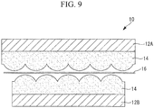
- Fig. 9 is a longitudinal sectional view illustrating the configuration of a bonded structure 10 according to the second embodiment prior to the application of pressure. Structural items in Fig. 9 that are the same as items in Fig. 7 are labeled using the same signs as Fig. 7 , and description of these items is omitted.
- Fig. 10 is a schematic view illustrating the positional change in axial strain before and after compression of the bonded structure 10 according to the second embodiment. In Fig. 10 , the case where axial strain occurs as contraction of the distributed optical fiber 16 is represented by a change in the positive direction.
- the adhesive 14 (adhesive layer) is applied so that the surface of the adhesive that contacts the distributed optical fiber 16 has a wave-like shape.
- the bonded structure 10 according to the second embodiment enables the distributed optical fiber 16 to be easily arranged in a wave-like shape, without using the sensitivity improvement element 30 (also see Fig. 10 ).
- the external shape of the distributed optical fiber 16 conforms to the contact surface with the adhesive layer and adopts a wave-like shape, and subsequently, the distributed optical fiber 16 contracts at that location, thereby increasing the axial strain, and meaning the bonding state in the bonded structure 10 can be detected.
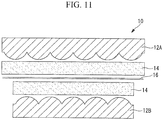
- Fig. 11 is a longitudinal sectional view illustrating the configuration of a bonded structure 10 according to the third embodiment prior to the application of pressure.
- Structural items in Fig. 11 that are the same as items in Fig. 7 are labeled using the same signs as Figs. 7 and 9 , and description of these items is omitted.
- Fig. 12 is a schematic view illustrating the positional change in axial strain before and after compression of the bonded structure 10 according to the third embodiment. In Fig. 12 , the case where axial strain occurs as contraction of the distributed optical fiber 16 is represented by a change in the positive direction.
- the surfaces of the laminated sheet 12A and the laminated sheet 12B that contact the distributed optical fiber 16 are formed with wave-like shapes.
- the bonded structure 10 according to the third embodiment enables the distributed optical fiber 16 to be easily arranged in a wave-like shape, without using the sensitivity improvement element 30 (also see Fig. 12 ).
- the external shape of the distributed optical fiber 16 conforms to the contact surface with the adhesive layer and adopts a wave-like shape, and subsequently, the distributed optical fiber 16 contracts at that location, thereby increasing the axial strain, and meaning the bonding state in the bonded structure 10 can be detected.
- both the laminated sheet 12A and the laminated sheet 12B are formed with wave-like surfaces, but this is not a limitation, and a configuration in which only one of the laminated sheet 12A and the laminated sheet 12B has a wave-like shape may also be used.
- Fig. 13 shows structural views of a distributed optical fiber 16 according to the fourth embodiment, wherein Fig. 13(A) is a perspective view, and Fig. 13(B) is a cross-sectional view.
- Fig. 14 is a longitudinal sectional view illustrating the configuration of a bonded structure 10 according to the fourth embodiment prior to the application of pressure.
- Fig. 15 is a schematic view illustrating the positional change in axial strain before and after compression of the bonded structure 10 according to the fourth embodiment. In Fig. 15 , the case where axial strain occurs as expansion of the distributed optical fiber 16 is represented by a change in the positive direction, and the case where axial strain occurs as contraction of the distributed optical fiber 16 is represented by a change in the negative direction.
- a cladding 16D that coats a core 16C of the distributed optical fiber 16 is formed with repeating large diameter sections 17A and small diameter sections 17B.
- the core 16C is provided linearly along the axial center of the cladding 16D.
- the bonded structure 10 according to the fourth embodiment can easily convert radial deformation in the distributed optical fiber 16 to axial deformation.
- the axial strain increases in those portions where the core 16C has expanded, whereas the axial strain decreases in those portions where the core 16C has contracted, thus enabling detection of the bonding state in the bonded structure 10.
- Fig. 16 is a longitudinal sectional view illustrating the configuration of a bonded structure 21 according to the fifth embodiment prior to the application of pressure.
- Fig. 17 is a diagram illustrating the bonded structure 21 of Fig. 16 following application of pressure in the vertical direction.
- Fig. 18 is a partial longitudinal sectional view describing a flexible member 40 according to the fifth embodiment.
- the bonded structure 21 includes the laminated sheet 12A, the laminated sheet 12B, the adhesive 14 that bonds the laminated sheet 12A and the laminated sheet 12B, and the distributed optical fiber 16 that is sandwiched between the laminated sheet 12A and the laminated sheet 12B.
- the bonded structure 21 also includes the flexible member 40.
- the distributed optical fiber 16 is sandwiched between the laminated sheet 12A and the laminated sheet 12B via the flexible member 40.
- the flexible member 40 is, for example, a cured adhesive.
- the adhesive may be a chemical-curing, thermosetting or thermoplastic adhesive. Which of a chemical-curing adhesive, a thermosetting adhesive and a thermoplastic adhesive is selected for the flexible member 40 can be determined as appropriate based on factors such as the shape of the flexible member 40 and the type of adhesive 14 used.
- the flexible member 40 and the adhesive 14 can be integrated (assimilated) during the bonding process for the bonded structure 21, meaning the flexible member 40 does not become an impurity within the bonded structure 21. As a result, the strength does not deteriorate near the locations where the flexible member 40 has been inserted.
- the flexible member 40 has an optical fiber embedment portion 41 and a plurality of feet 42.
- the optical fiber embedment portion 41 has a sheet-like form.
- the distributed optical fiber 16 is embedded in the optical fiber embedment portion 41.
- the distributed optical fiber 16 is embedded in the optical fiber embedment portion 41 by being sandwiched between an optical fiber embedment portion 41A and an optical fiber embedment portion 41B.
- a thickness t 1 of the optical fiber embedment portion 41 with the distributed optical fiber 16 embedded therein is typically at least 10 ⁇ m but not more than 1,000 ⁇ m, and is preferably at least 50 ⁇ m but not more than 200 ⁇ m. If the thickness t 1 is too thin, then the optical fiber tends to become exposed through the element. If the thickness t 1 is too great, then there is a strong possibility that the entire element including the optical fiber may protrude from the adhesive layer.
- the thickness t 1 of the optical fiber embedment portion 41 may be set within the above range in accordance with the thickness of the adhesive (the adhesive layer) and the bonding pressure and the like.
- the plurality of feet 42 are provided so as to protrude from the surface of the optical fiber embedment portion 41B. Although not indicated in Figs. 16 to 18 , the feet 42 extend across the width direction of the sheet (in the direction perpendicular to the surface of the paper).
- the plurality of feet 42 are arranged on the surface of the optical fiber embedment portion 41B with a prescribed spacing s between the feet.
- the prescribed spacing s is greater than a height t 2 of the flexible member 40 (s/t 2 >1).
- the height t 2 of the flexible member 40 is the distance from the tip of the feet to the surface of the optical fiber embedment portion 41A.
- a width w of each of the feet 42 is less than the prescribed spacing s (w ⁇ s).
- the tips of the plurality of feet 42 contact the laminated sheet 12B.
- the plurality of feet 42 support the optical fiber embedment portion 41 so that a gap is formed between the optical fiber embedment portion 41B and the laminated sheet 12B.
- the bonded structure 21 according to the fifth embodiment can easily convert radial deformation in the distributed optical fiber 16 to axial deformation. This enables detection of the bonding state in the bonded structure 21.
- the flexible member 40 by setting the thickness t 1 of the optical fiber embedment portion 41, the thickness t 2 of the flexible member 40, the width w of the feet 42, and the spacing s between adjacent feet 42 so as to satisfy the size correlations described above, the flexible member 40 can be warped in a stable manner, enabling favorable detection of the bonding state in the bonded structure 21.
- Fig. 19 illustrates test results for the bonded structure 21 according to the fifth embodiment.
- the test piece was a bonded structure 21 in which the flexible member 40 containing the embedded distributed optical fiber 16 was sandwiched between laminated sheets 12A and 12B composed of aluminum sheets, with pressure than applied to this bonded structure 21 from the vertical direction.
- the “Length (m)” shown along the horizontal axis of Fig. 19 represents the length of the distributed optical fiber 16, and indicates the position of pressure detection.
- the “Strain ( ⁇ )” shown along the vertical axis of Fig. 19 is a value indicating the strain in the axial direction of the distributed optical fiber 16, wherein a positive value indicates an expansion and a negative value indicates a contraction.
- the portion where pressure was applied to the bonded structure 21 (hereafter referred to as the "compressed portion") is from about 5.43 m to 5.56 m.
- the pressure applied to the bonded structure 21 in the test was within a range from 0.18 atm (about 0.018 MPa) to 0.97 atm (about 0.1 MPa).
- Fig. 20 illustrates test results for the bonded structure 21 according to the first embodiment.
- the test piece was the bonded structure 10 having the distributed optical fiber 16 sandwiched between the sensitivity improvement element 30 and the laminated sheets 12A and 12B, and pressure was applied from the vertical direction of the bonded structure 10.
- the distributed optical fiber 16 used was the same as that used in the tests of Fig. 19 .
- the “Length (m)” shown along the horizontal axis of Fig. 20 represents the length of the distributed optical fiber 16, and indicates the position of pressure detection.
- the “Strain ( ⁇ )” shown along the vertical axis of Fig. 20 is a value indicating the strain in the axial direction of the distributed optical fiber 16, wherein a positive value indicates an expansion and a negative value indicates a contraction.
- the portion where pressure was applied to the bonded structure 21 (hereafter referred to as the "compressed portion") is from about 7.052 m to 7.156 m.
- the pressure applied to the bonded structure 10 in the test was within a range from 0.18 atm (about 0.018 MPa) to 0.98 atm (about 0.1 MPa).
- each of the above embodiments was described using the case where the laminated sheets 12A and 12B of a carbon fiber composite material were used as the members to be bonded, but the present invention is not limited to such members, and the members to be bonded may be fiber-reinforced resin-based composite materials reinforced with glass fiber or the like, or metal materials such as aluminum alloys.
- the bonded structure 10 according to the embodiments described above may also be used for repairing damaged composite material structures.
- Fig. 21 is a schematic view illustrating an example of a bonded structure 10 that can be used for repair.
- the distributed optical fiber 16 is arranged so as to extend along the direction perpendicular to the surface of the paper.
- the distributed optical fiber 16 is arranged on a damaged laminated sheet 12C (item to be bonded) within a region requiring repair. Then, a release film 32 provided with a thermocouple, the adhesive 14, and a repair ply 12D that acts as the laminated sheet for repairing the region requiring repair are stacked on top of the distributed optical fiber 16. The region requiring repair is then covered with a bagging film 34, the structure is subjected to vacuum evacuation, and the region requiring repair is autoclaved.
- the temperatures of the repair ply 12D and the laminated sheet 12C are measured by the thermocouple, and the pressure is measured by the distributed optical fiber 16. This enables confirmation to be made that the temperature and pressure for the repair are appropriate, namely that the autoclaving conditions are appropriate.
- the release film 32 is peeled off, and the distributed optical fiber 16 is removed.
- the adhesive 14 and the repair ply 12D are then once again stacked in the region requiring repair, and following covering with the bagging film 34, autoclaving is performed under the confirmed appropriate conditions.
- An optical fiber according to the fourth embodiment described above may also be used as the distributed optical fiber 16. Further, an adhesive according to the second embodiment may be used as the adhesive 14. A structure according to the third embodiment may be used as the repair ply 12D. The sensitivity improvement element 30 according to the first embodiment may also be used.
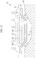
- Fig. 22 is a schematic view illustrating an example of a bonded structure 21 that can be used for repair.
- Fig. 22 illustrates the state prior to pressure application.
- the distributed optical fiber 16 is arranged so as to extend left top right along the surface of the paper.
- the flexible member 40 containing the embedded distributed optical fiber 16 is arranged on the region requiring repair of the damaged laminated sheet 12C (item to be bonded).
- the adhesive 14 and the repair ply 12D used as the laminated sheet for repairing the region requiring repair are then stacked on top of the flexible member 40.
- a separate release film 32 is disposed between the flexible member 40 and the adhesive 14, between the adhesive 14 and the repair ply 12D, and on top of the repair ply 12D.
- the region requiring repair is then covered with a bagging film 34, and pressurized by vacuum evacuation or the like.
- the pressure applied to the repair ply 12D and the laminated sheet 12C is measured by the distributed optical fiber 16. This enables confirmation to be made that the pressure for the repair is appropriate.
- the release films 32 are peeled off, and the flexible member 40 is removed.
- the adhesive 14 and the repair ply 12D are then once again stacked in the region requiring repair, and following covering with the bagging film 34, the repair is performed under the confirmed appropriate conditions.
Abstract
Description
- The present invention relates to a bonded structure, a method for manufacturing the same, and a bonding state detection method.
- Conventionally, carbon fiber composite materials have been used in structures such as aircraft structures where weight reduction is required.
- An example of a method used for monitoring the resin curing of carbon fiber composite materials is a method using an optical fiber provided with an internal grating sensor, such as the method disclosed in Patent Literature (PTL) 1.
- Members of carbon fiber composite materials are generally joined together using fasteners such as rivets or bolts.
- When joining members together, using an adhesive is optimal in terms of factors such as weight reduction and operational efficiency, but evaluation of the bond quality is necessary. Evaluation of the bond quality is performed by bonding the members together with an adhesive, and then conducting an ultrasonic flaw detection inspection or the like.
- {PTL 1}
Japanese Translation of PCT International Application, Publication No. 2000-501176 - However, in an ultrasonic flaw detection inspection, although defects such as voids in the adhesive layer or peeling of the members can be detected, the bonding strength cannot be evaluated. This is because the bonding strength depends on factors such as the pressure applied to the members during bonding, and pressure cannot be examined in an ultrasonic flaw detection inspection. Moreover, ultrasonic flaw detection inspections require considerable time and effort, and also require that the inspector is appropriately qualified.
- When carbon fiber composite materials are used as members, bonding of the members is conducted, for example, during autoclave molding. During autoclave molding, although the autoclave pressure and the bag pressure are measured, the pressure of the bond itself is not measured.
- As a result of these circumstances, when members are joined together by bonding, the resulting structures have significant safety tolerances, and therefore in those locations where safety is particularly important, the members tend to be joined by fasteners rather than bonded using an adhesive.
- The present invention has been developed in light of these circumstances, and has an object of providing a bonded structure, a method for manufacturing the same, and a bonding state detection method which are capable of determining whether or not members are bonded together appropriately.
- In order to achieve the above object, the bonded structure, the method for manufacturing the same, and the bonding state detection method according to the present invention employ the following aspects.
- A bonded structure according to a first aspect of the present invention includes a first member, a second member, an adhesive that bonds the first member and the second member together, and a distributed optical fiber that is sandwiched between the first member and the second member, wherein the cross-sectional shape of the distributed optical fiber deforms in accordance with the bonding state. In this first aspect, the bonding state between the first member and the second member is detected on the basis of the axial deformation in the distributed optical fiber converted from the radial deformation.
- According to this configuration, the first member and the second member are bonded together by applying an appropriate pressure with the adhesive disposed between the members. The distributed optical fiber sandwiched between the first member and the second member is used for detecting the bonding state between the first member and the second member.
- Optical fibers include multipoint optical fibers and distributed optical fibers.
- In multipoint optical fibers, a diffraction grating provided in a non-continuous manner in the optical fiber functions as a sensor. Accordingly, when a multipoint optical fiber is used as a pressure sensor, the bonding state can only be detected at positions where the grating is provided, namely only at non-continuous locations along the axial direction of the multipoint optical fiber, meaning there are locations where detection of the bonding state is impossible.
- On the other hand, in the case of distributed optical fibers, the entire fiber in the axial direction functions as a sensor. Further, changes in the optical spectrum in the distributed optical fiber are relatively insensitive to radial deformation in the distributed optical fiber, but very sensitive to axial deformation. Accordingly, in this configuration, by converting radial deformation in the distributed optical fiber into axial deformation, the pressure applied to the distributed optical fiber is detected on the basis of this axial deformation. As a result, the distributed optical fiber can be used to continuously detect the bonding state between the first member and the second member.
- As described above, in this configuration, by converting radial deformation in the distributed optical fiber into axial deformation, the bonding state can be detected continuously along the axial direction of the distributed optical fiber, meaning a determination can be made as to whether or not the members are bonded together appropriately.
- In the first aspect described above, the distributed optical fiber has a property of contracting or expanding when the first member and the second member reach a bonded state compared with the case where the first member and the second member are in an unbonded state.
- According to this configuration, the distributed optical fiber contracts or expands when the first member and the second member reach a bonded state. This contraction or expansion of the distributed optical fiber means radial deformation of the distributed optical fiber has been converted to axial deformation.
- Accordingly, this configuration can easily convert radial deformation in the distributed optical fiber to axial deformation.
- In the first aspect described above, when the first member and the second member are in an unbonded state, the distributed optical fiber may be arranged in a wave-like shape relative to the direction of the first member and the second member.
- According to this configuration, by arranging the distributed optical fiber in a wave-like shape in an unbonded state, when the first member and the second member reach a bonded state and pressure is applied in the radial direction of the distributed optical fiber, the distributed optical fiber contracts linearly. Accordingly, in this configuration, radial deformation in the distributed optical fiber can be easily converted to axial deformation.
- In the first aspect described above, the distributed optical fiber may be sandwiched between the first member and the second member via a wave-like member having a wave-like surface.
- According to this configuration, the distributed optical fiber can be easily arranged in a wave-like shape.
- In the first aspect described above, the surface of the adhesive that contacts the distributed optical fiber may have a wave-like shape.
- According to this configuration, the distributed optical fiber can be easily arranged in a wave-like shape.
- In the first aspect described above, at least one of the first member and the second member may have a wave-like surface that contacts the distributed optical fiber.
- According to this configuration, the distributed optical fiber can be easily arranged in a wave-like shape.
- In the first aspect described above, the cladding that coats the core of the distributed optical fiber may be formed with repeating large diameter sections and small diameter sections.
- According to this configuration, when pressure is applied in the radial direction of the distributed optical fiber, the large diameter sections contract, whereas the small diameter sections expand. As a result, the core of the distributed optical fiber expands in the axial direction.
- Accordingly, this configuration can easily convert radial deformation in the distributed optical fiber to axial deformation.
- In the first aspect described above, the distributed optical fiber may be sandwiched between the first member and the second member in a state embedded in a flexible member. The flexible member has an optical fiber embedment portion in which the distributed optical fiber is embedded, and a plurality of feet protruding from the optical fiber embedment portion, with the plurality of feet arranged with spaces therebetween.
- According to this configuration, by embedding the distributed optical fiber in a flexible member, and then disposing the flexible member between the first member and the second member, when the first member and the second member reach a bonded state and pressure is applied in the radial direction of the distributed optical fiber, the distributed optical fiber expands. As a result, this configuration can easily convert radial deformation in the distributed optical fiber to axial deformation.
- A method for manufacturing a bonded structure according to a second aspect of the present invention includes a step of applying an adhesive to at least one of a first member and a second member, and a step of sandwiching a distributed optical fiber between the first member and the second member to which the adhesive has been applied, and applying pressure, thereby deforming the cross-sectional shape of the distributed optical fiber and bonding the first member and the second member together.
- In the second aspect described above, the radial deformation in the distributed optical fiber that occurs as a result of the pressure application is converted to axial deformation, and the bonding state between the first member and the second member is detected on the basis of this axial deformation.
- In the second aspect described above, the distributed optical fiber is formed from a material that has a property of contracting or expanding when the first member and the second member reach a bonded state compared with the case where the first member and the second member are in an unbonded state.
- In the second aspect described above, when the first member and the second member are in an unbonded state, the distributed optical fiber may be arranged in a wave-like shape relative to the direction of the first member and the second member.
- In the second aspect described above, the distributed optical fiber may be sandwiched between the first member and the second member via a wave-like member having a wave-like surface.
- In the second aspect described above, the surface of the adhesive that contacts the distributed optical fiber may have a wave-like shape.
- In the second aspect described above, at least one of the first member and the second member may be formed with a wave-like surface that contacts the distributed optical fiber.
- In the second aspect described above, the distributed optical fiber may be sandwiched between the first member and the second member via a flexible member having an optical fiber embedment portion in which the distributed optical fiber is embedded and a plurality of feet protruding from the optical fiber embedment portion and arranged with spaces therebetween.
- A bonding state detection method according to a third aspect of the present invention includes a first step of bonding a first member and a second member with an adhesive while sandwiching a distributed optical fiber between the members, and a second step of detecting the bonding state between the first member and the second member on the basis of the axial deformation in the distributed optical fiber converted from the radial deformation.
- In the third aspect described above, the distributed optical fiber may be arranged on the first member, a release film, the aforementioned adhesive and the second member then stacked thereon and pressure applied, and the appropriateness of the pressure then detected by the distributed optical fiber.
- The present invention has the excellent effect of enabling a determination to be made as to whether or not members are bonded together appropriately.
-
- {
Fig. 1 } An exploded perspective view illustrating a bonded structure according to a first embodiment of the present invention. - {
Fig. 2 } A schematic plan view of a measuring diagnostic device according to the first embodiment of the present invention. - {
Fig. 3 } A diagram illustrating the optical spectrum when no pressure is applied to an optical fiber according to the first embodiment of the present invention. - {
Fig. 4 } A diagram illustrating the optical spectrum when pressure is applied to an optical fiber according to the first embodiment of the present invention. - {
Fig. 5 } A schematic view designating radial deformation and axial deformation of a distributed optical fiber according to the first embodiment of the present invention. - {
Fig. 6 } Schematic views illustrating the arrangement of a distributed optical fiber according to the first embodiment of the present invention, wherein (A) illustrates an unbonded state, and (B) illustrates a bonded state. - {
Fig. 7 } A schematic view illustrating the arrangement of a distributed optical fiber according to the first embodiment of the present invention. - {
Fig. 8 } A graph illustrating the test results for a bonded structure using a sensitivity improvement element according to the first embodiment of the present invention. - {
Fig. 9 } A longitudinal sectional view illustrating the configuration of a bonded structure according to a second embodiment of the present invention. - {
Fig. 10 } A schematic view illustrating the positional change in axial strain before and after compression of a bonded structure according to the second embodiment of the present invention. - {
Fig. 11 } A longitudinal sectional view illustrating the configuration of a bonded structure according to a third embodiment of the present invention. - {
Fig. 12 } A schematic view illustrating the positional change in axial strain before and after compression of a bonded structure according to the third embodiment of the present invention. - {
Fig. 13 } Structural views of a distributed optical fiber according to a fourth embodiment of the present invention, wherein (A) is a perspective view, and (B) is a cross-sectional view. - {
Fig. 14 } A longitudinal sectional view illustrating the configuration of a bonded structure according to the fourth embodiment of the present invention. - {
Fig. 15 } A schematic view illustrating the positional change in axial strain before and after compression of a bonded structure according to the fourth embodiment of the present invention. - {
Fig. 16 } A longitudinal sectional view illustrating the configuration of a bonded structure according to a fifth embodiment of the present invention. - {
Fig. 17 } A diagram illustrating the bonded structure ofFig. 16 following application of pressure in the vertical direction. - {
Fig. 18 } A partial longitudinal sectional view illustrating the configuration of a flexible member according to the fifth embodiment of the present invention. - {
Fig. 19 } A graph illustrating the test results for a bonded structure using a flexible member according to the fifth embodiment of the present invention. - {
Fig. 20 } A graph illustrating the test results for a bonded structure using a sensitivity improvement element according to the first embodiment of the present invention. - {
Fig. 21 } A schematic view illustrating an example of a bonded structure according to another embodiment of the present invention. - {
Fig. 22 } A schematic view illustrating an example of a bonded structure according to yet another embodiment of the present invention. - Embodiments of the bonded structure and the bonding state detection method of the present invention are described below with reference to the drawings.
- 1
- A first embodiment of the present invention is described below.
-
Fig. 1 is an exploded perspective view illustrating a bondedstructure 10 according to the first embodiment. In the first embodiment, laminated sheets of a carbon fiber composite material are used as examples of the members to be bonded. By combining a plurality of structures, the bondedstructure 10 can be used, for example, as a structural material for aircraft, automobiles, and wind turbines and the like. - The bonded
structure 10 includes alaminated sheet 12A, alaminated sheet 12B, an adhesive 14 that bonds thelaminated sheet 12A and thelaminated sheet 12B, and a distributedoptical fiber 16 that is sandwiched between thelaminated sheet 12A and thelaminated sheet 12B. The distributedoptical fiber 16 is used as a pressure sensor for detecting the bonding state between thelaminated sheet 12A and thelaminated sheet 12B based on the axial deformation of the optical fiber. Details concerning the axial deformation are described below. The distributedoptical fiber 16 is, for example, a single-mode fiber having a cladding diameter of 125 µm and having a circular cross-sectional shape. - The distributed
optical fiber 16 has a property of contracting or expanding when thelaminated sheet 12A and thelaminated sheet 12B reach a bonded state compared with the case where thelaminated sheet 12A and thelaminated sheet 12B are in an unbonded state. The cross-sectional shape of the distributed optical fiber 16 (the transverse sectional shape perpendicular to the axial direction of the distributed optical fiber 16) when thelaminated sheet 12A and thelaminated sheet 12B reach a bonded state is an elliptical shape. The transverse sectional shape describes the cross-sectional shape when the distributedoptical fiber 16 is cut across the length of the fiber. - The adhesive 14 is used, for example, in the form of an adhesive layer. There are no particular limitations on the type of
adhesive 14 used, and for example an epoxy resin-based adhesive may be used. - Prior to bonding with the adhesive 14, at least one of the
laminated sheets - The planar shapes of the
laminated sheets Fig. 1 are square, but this is merely an example, and the planar shapes of thelaminated sheets laminated sheets Fig. 1 , the adhesive 14 is only applied to one of thelaminated sheets laminated sheets - The distributed
optical fiber 16 illustrated inFig. 1 is bent a plurality of times with anend section 16A and anend section 16B both protruding from the same side of thelaminated sheets optical fiber 16 need not necessarily be sandwiched in a bent configuration, and theend section 16A and theend section 16B may protrude from different sides of thelaminated sheets optical fiber 16. - As illustrated in
Fig. 2 , theend sections optical fiber 16 are connected to a measuringdiagnostic device 22 viaconnectors 20. The measuringdiagnostic device 22 inputs light of a prescribed wavelength from theend section 16A (input port) of the distributedoptical fiber 16, the light is reflected inside the distributedoptical fiber 16, and the light exiting from theend section 16A (hereafter referred to as "reflected light") is detected and an optical spectrum is obtained. - The
laminated sheets laminated sheets optical fiber 16. In the following description, the application of pressure to thelaminated sheets - Birefringence in an
optical fiber 15 is described below with reference toFigs. 3 and 4 . - In a state where no pressure is applied to the
optical fiber 15, the optical spectrum has a single peak, as illustrated inFig. 3 . In contrast, when pressure is applied to theoptical fiber 15 from only a prescribed direction (the vertical direction inFigs. 3 and 4 ), then as illustrated inFig. 4 , the cross-sectional shape of theoptical fiber 15, which was circular, deforms and changes, for example to an elliptical shape (a flattened circle or oval shape). As a result, the optical spectrum changes to a shape having multiple (for example two) peaks. This is birefringence of theoptical fiber 15. When thelaminated sheets optical fiber 15 sandwiched between thelaminated sheets - Examples of the
optical fiber 15 include multipoint optical fibers and the distributedoptical fiber 16 used in the first embodiment. - In multipoint optical fibers, a diffraction grating provided in a non-continuous manner in the core functions as a sensor. In multipoint optical fibers, the optical spectrum is sensitive to radial deformation in the multipoint optical fiber. In other words, when pressure is applied, the optical spectrum output from the multipoint optical fiber changes in the manner described using
Figs. 3 and 4 . - However, if a multipoint optical fiber is used as a pressure sensor, then pressure detection can only be conducted at locations where the grating is provided. In other words, the bonding state can only be detected at non-continuous locations along the axial direction of the multipoint optical fiber. As a result, locations where the grating is not provided are excluded from detection of the bonding state.
- On the other hand, the distributed
optical fiber 16 used in the first embodiment functions as a sensor along the entire length of the fiber in the axial direction. Changes in the optical spectrum in the distributedoptical fiber 16 are relatively insensitive to radial deformation of the distributed optical fiber, but very sensitive to axial deformation. - Accordingly, in order to detect the bonding state between the
laminated sheet 12A and thelaminated sheet 12B using the distributedoptical fiber 16 that is sensitive to axial deformation, the bondedstructure 10 according to the first embodiment converts radial deformation in the distributedoptical fiber 16 into axial deformation, as illustrated inFig. 5 . - When the distributed
optical fiber 16 deforms in the axial direction, namely contracts or expands, the peak position of the reflected light differs from the position prior to contraction or expansion. Accordingly, by measuring the displacement in the peak position of the reflected light before and after the contraction or expansion, the amount of deformation (amount of strain) in the axial direction of the distributedoptical fiber 16 can be detected. As described above, the amount of deformation (amount of strain) in the axial direction indicates the bonding state between thelaminated sheets - Accordingly, in the bonded
structure 10 used in the first embodiment, axial deformation in the distributedoptical fiber 16 can be used to detect the bonding state between thelaminated sheet 12A and thelaminated sheet 12B continuously along the axial direction of the distributedoptical fiber 16. - In the first embodiment, in which the members to be bonded are the
laminated sheets laminated sheets optical fiber 16. Accordingly, in the first embodiment, when thelaminated sheets - Next is a description of specific methods for converting radial deformation in the distributed
optical fiber 16 into axial deformation. - The distributed
optical fiber 16 according to the first embodiment is arranged so that when thelaminated sheet 12A and thelaminated sheet 12B reach a bonded state, the optical fiber contracts or expands compared with the case where thelaminated sheet 12A and thelaminated sheet 12B are in an unbonded state. - When the
laminated sheet 12A and thelaminated sheet 12B reach a bonded state, the contraction or expansion of the distributedoptical fiber 16 accompanying the application of pressure in the radial direction of the distributedoptical fiber 16 means that radial deformation in the distributedoptical fiber 16 has been converted to axial deformation. -
Fig. 6 (Fig. 6(A) and Fig. 6(B) ) are schematic views illustrating an example of the arrangement of the distributedoptical fiber 16 according to the first embodiment of the present invention. InFig. 6 (Fig. 6(A) and Fig. 6(B) ), the distributedoptical fiber 16 is embedded in a sensitivity improvement element described below. -
Fig. 6(A) illustrates the case where thelaminated sheet 12A (not shown in the drawing) and thelaminated sheet 12B (not shown in the drawing) are in an unbonded state (an uncompressed state). - When the
laminated sheet 12A and thelaminated sheet 12B are in an unbonded state, the distributedoptical fiber 16 is arranged in a wave-like shape relative to the direction of thelaminated sheet 12A and thelaminated sheet 12B. In other words, the distributedoptical fiber 16 is arranged so that the direction of the curves (the inflection points) of the optical fiber is along the lamination direction of thelaminated sheet 12A and thelaminated sheet 12B. -
Fig. 6(B) illustrates the case where thelaminated sheet 12A and thelaminated sheet 12B are in a bonded state. - As illustrated in
Fig. 6(B) , when pressure is applied in the radial direction of the distributedoptical fiber 16 in order to bond thelaminated sheet 12A and thelaminated sheet 12B together, a force is applied in substantially a perpendicular direction to the compression direction, and linear deformation of the wave-like arranged distributedoptical fiber 16 causes contraction in the axial direction. As a result, the radial deformation in the distributedoptical fiber 16 is easily converted to axial deformation. -
Fig. 7 is a schematic view illustrating the arrangement of the distributedoptical fiber 16 according to the first embodiment. As illustrated inFig. 7 , the distributedoptical fiber 16 according to the first embodiment is sandwiched between thelaminated sheet 12A and thelaminated sheet 12B via asensitivity improvement element 30. Thesensitivity improvement element 30 is a wave-like member having a wave-shaped surface. - This wave-like shape could also be described as a shape having continuous undulations. The wave-like shape may have arc-shaped undulations as illustrated in the example of
Fig. 7 , or polygonal undulations such as triangular or square shapes. - The
sensitivity improvement element 30 may, for example, be a cured adhesive of an adhesive such as a chemical-curing, thermosetting or thermoplastic adhesive. - A chemical-curing adhesive is an adhesive in which, for example, the curing reaction is initiated by mixing two liquids composed of a main agent and a curing agent respectively. An example of a chemical-curing adhesive is EA9394 manufactured by Henkel Corporation.
- A thermosetting adhesive is an adhesive that undergoes a curing reaction by application of external heat to the adhesive. An example of a thermosetting adhesive is FM300-2 manufactured by Cytec Solvay Group.
- A thermoplastic adhesive is an adhesive in which a polymerization reaction is initiated by applying heat to the adhesive, and the curing reaction then proceeds upon heat dissipation. An example of a thermoplastic adhesive is PPS resin (Poly Phenylene Sulfide resin).
- A shim of an uncured prepreg or the like used for regulating the space between the bonded portions may be used as the
sensitivity improvement element 30. - In the first embodiment, an element prepared by curing the aforementioned FM300-2 manufactured by Cytec Solvay Group was used as one example of the
sensitivity improvement element 30. In one example of the first embodiment, FM300-2 manufactured by Cytec Solvay Group was also used as the adhesive 14. - In this manner, by forming the
sensitivity improvement element 30 by curing the same adhesive as that used for the adhesive 14, thesensitivity improvement element 30 and the adhesive 14 can be integrated (assimilated) during the bonding process for the bondedstructure 10, meaning thesensitivity improvement element 30 does not become an impurity within the bondedstructure 10. As a result, the strength does not deteriorate near the locations where thesensitivity improvement element 30 has been inserted. - Which of a chemical-curing adhesive, a thermosetting adhesive and a thermoplastic adhesive is selected for the
sensitivity improvement element 30 can be determined as appropriate based on factors such as the shape of thesensitivity improvement element 30 and the type ofadhesive 14 used. -
Fig. 8 illustrates the test results (dashed lines a and b) for a bondedstructure 10 according to the first embodiment that does not use thesensitivity improvement element 30, and the test results (solid lines A and B) for a bondedstructure 10 using thesensitivity improvement element 30. The test piece was, for example, a bondedstructure 10 in which the distributedoptical fiber 16 was sandwiched between thesensitivity improvement element 30 and thelaminated sheets structure 10 from the vertical direction. - The "Length (m)" shown along the horizontal axis of
Fig. 8 represents the length of the distributedoptical fiber 16, and indicates the position of pressure detection. The "Strain (µε)" shown along the vertical axis ofFig. 8 is a value indicating the strain in the axial direction of the distributedoptical fiber 16, wherein a positive value indicates an expansion and a negative value indicates a contraction. - In the test, the portion where pressure was applied to the bonded structure 10 (hereafter referred to as the "compressed portion") is from about 6.5 m to 6.6 m. The pressure applied to the bonded
structure 10 in the test was 0.1 MPa (dashed line a and solid line A) or 0.4 MPa (dashed line b and solid line B). - In
Fig. 8 , the dot and dash line O represents the case where the pressure is 0 MPa, namely the case where no compression was applied, and represents no axial strain as indicated by Strain = 0. - The dashed lines a and b indicating the test results for the bonded
structure 10 not using thesensitivity improvement element 30 displayed slight fluctuations in the axial strain in the compressed portion, but the changes did not exhibit good sensitivity to the pressure. - On the other hand, the solid lines A and B representing the test results for the bonded
structure 10 using thesensitivity improvement element 30 show large changes in the negative value of the axial strain in the compressed portion. The changes in the solid line B (0.4 MPa) that indicates the test conducted at higher pressure were larger than the changes in the solid line A (0.1 MPa). - In the solid lines A and B, based on the fact that a negative change in the axial strain occurs continuously in the compressed portion, it is evident that the bonded
structure 10 using thesensitivity improvement element 30 is continuously detecting the bonding state. - By preparing in advance information (for example, tabulated information) indicating the relationship between the size of the axial strain and the pressure, and then referencing the tabulated information against actually measured axial strain values, the pressure applied to the bonded
structure 10 can be determined from the measured axial strain. - As described above, the bonded
structure 10 according to the first embodiment includes thelaminated sheet 12A, thelaminated sheet 12B, the adhesive 14 that bonds thelaminated sheet 12A and thelaminated sheet 12B together, and the distributedoptical fiber 16 sandwiched between thelaminated sheet 12A and thelaminated sheet 12B. The bonding state between thelaminated sheet 12A and thelaminated sheet 12B is detected on the basis of the axial deformation in the distributedoptical fiber 16 converted from the radial deformation. - In this manner, in the bonded
structure 10 according to the first embodiment, the bonding state can be detected continuously along the axial direction of the distributedoptical fiber 16 by converting the radial deformation in the distributedoptical fiber 16 to axial deformation, and therefore a determination can be made as to whether or not the members have been appropriately bonded together. - More specifically, in the case where pressure is applied during the bonding step for the bonded
structure 10, the quality following bonding has conventionally been confirmed by detecting the pressure applied to the entire bondedstructure 10, but because the distributedoptical fiber 16 enables the pressure to be detected at the actual bonding location, the adequacy of the bonding step can be evaluated more precisely. - A second embodiment of the present invention is described below.
-
Fig. 9 is a longitudinal sectional view illustrating the configuration of a bondedstructure 10 according to the second embodiment prior to the application of pressure. Structural items inFig. 9 that are the same as items inFig. 7 are labeled using the same signs asFig. 7 , and description of these items is omitted.Fig. 10 is a schematic view illustrating the positional change in axial strain before and after compression of the bondedstructure 10 according to the second embodiment. InFig. 10 , the case where axial strain occurs as contraction of the distributedoptical fiber 16 is represented by a change in the positive direction. - As illustrated in
Fig. 9 , in the bondedstructure 10 according to the second embodiment, the adhesive 14 (adhesive layer) is applied so that the surface of the adhesive that contacts the distributedoptical fiber 16 has a wave-like shape. As a result, the bondedstructure 10 according to the second embodiment enables the distributedoptical fiber 16 to be easily arranged in a wave-like shape, without using the sensitivity improvement element 30 (also seeFig. 10 ). - As illustrated in
Fig. 10 , when the bondedstructure 10 according to the second embodiment is compressed, the external shape of the distributedoptical fiber 16 conforms to the contact surface with the adhesive layer and adopts a wave-like shape, and subsequently, the distributedoptical fiber 16 contracts at that location, thereby increasing the axial strain, and meaning the bonding state in the bondedstructure 10 can be detected. - A third embodiment of the present invention is described below.
-
Fig. 11 is a longitudinal sectional view illustrating the configuration of a bondedstructure 10 according to the third embodiment prior to the application of pressure. Structural items inFig. 11 that are the same as items inFig. 7 are labeled using the same signs asFigs. 7 and9 , and description of these items is omitted.Fig. 12 is a schematic view illustrating the positional change in axial strain before and after compression of the bondedstructure 10 according to the third embodiment. InFig. 12 , the case where axial strain occurs as contraction of the distributedoptical fiber 16 is represented by a change in the positive direction. - As illustrated in
Fig. 11 , in the bondedstructure 10 according to the third embodiment, the surfaces of thelaminated sheet 12A and thelaminated sheet 12B that contact the distributedoptical fiber 16 are formed with wave-like shapes. As a result, the bondedstructure 10 according to the third embodiment enables the distributedoptical fiber 16 to be easily arranged in a wave-like shape, without using the sensitivity improvement element 30 (also seeFig. 12 ). - As illustrated in
Fig. 12 , when the bondedstructure 10 according to the third embodiment is compressed, the external shape of the distributedoptical fiber 16 conforms to the contact surface with the adhesive layer and adopts a wave-like shape, and subsequently, the distributedoptical fiber 16 contracts at that location, thereby increasing the axial strain, and meaning the bonding state in the bondedstructure 10 can be detected. - In the example of
Fig. 11 , both thelaminated sheet 12A and thelaminated sheet 12B are formed with wave-like surfaces, but this is not a limitation, and a configuration in which only one of thelaminated sheet 12A and thelaminated sheet 12B has a wave-like shape may also be used. - A fourth embodiment of the present invention is described below.
-
Fig. 13 (Fig. 13(A) and Fig. 13(B) ) shows structural views of a distributedoptical fiber 16 according to the fourth embodiment, whereinFig. 13(A) is a perspective view, andFig. 13(B) is a cross-sectional view.Fig. 14 is a longitudinal sectional view illustrating the configuration of a bondedstructure 10 according to the fourth embodiment prior to the application of pressure.Fig. 15 is a schematic view illustrating the positional change in axial strain before and after compression of the bondedstructure 10 according to the fourth embodiment. InFig. 15 , the case where axial strain occurs as expansion of the distributedoptical fiber 16 is represented by a change in the positive direction, and the case where axial strain occurs as contraction of the distributedoptical fiber 16 is represented by a change in the negative direction. - Structural items in
Fig. 13 (Fig. 13(A) and Fig. 13(B) ) throughFig. 15 that are the same as items inFig. 7 are labeled using the same signs asFig. 7 , and description of these items is omitted. - As illustrated in
Fig. 13 (Fig. 13(A) and Fig. 13(B) ) andFig. 14 , acladding 16D that coats acore 16C of the distributedoptical fiber 16 is formed with repeatinglarge diameter sections 17A andsmall diameter sections 17B. Thecore 16C is provided linearly along the axial center of thecladding 16D. - As illustrated in
Fig. 15 , when thelaminated sheet 12A and thelaminated sheet 12B reach a bonded state and pressure is applied in the radial direction of the distributedoptical fiber 16, thelarge diameter sections 17A contract, while thesmall diameter sections 17B expand. This causes thecore 16C of the distributedoptical fiber 16 to expand in the axial direction. - As a result, the bonded
structure 10 according to the fourth embodiment can easily convert radial deformation in the distributedoptical fiber 16 to axial deformation. - As illustrated in
Fig. 15 , the axial strain increases in those portions where thecore 16C has expanded, whereas the axial strain decreases in those portions where thecore 16C has contracted, thus enabling detection of the bonding state in the bondedstructure 10. - A fifth embodiment of the present invention is described below.
-
Fig. 16 is a longitudinal sectional view illustrating the configuration of a bondedstructure 21 according to the fifth embodiment prior to the application of pressure.Fig. 17 is a diagram illustrating the bondedstructure 21 ofFig. 16 following application of pressure in the vertical direction.Fig. 18 is a partial longitudinal sectional view describing aflexible member 40 according to the fifth embodiment. - Structural items in
Fig. 16 to Fig. 18 that are the same as items inFig. 7 are labeled using the same signs asFig. 7 , and description of these items is omitted. - In a similar manner to the bonded
structure 10, the bondedstructure 21 includes thelaminated sheet 12A, thelaminated sheet 12B, the adhesive 14 that bonds thelaminated sheet 12A and thelaminated sheet 12B, and the distributedoptical fiber 16 that is sandwiched between thelaminated sheet 12A and thelaminated sheet 12B. The bondedstructure 21 also includes theflexible member 40. The distributedoptical fiber 16 is sandwiched between thelaminated sheet 12A and thelaminated sheet 12B via theflexible member 40. - The
flexible member 40 is, for example, a cured adhesive. The adhesive may be a chemical-curing, thermosetting or thermoplastic adhesive. Which of a chemical-curing adhesive, a thermosetting adhesive and a thermoplastic adhesive is selected for theflexible member 40 can be determined as appropriate based on factors such as the shape of theflexible member 40 and the type ofadhesive 14 used. By forming theflexible member 40 by curing the same adhesive as that used for the adhesive 14, theflexible member 40 and the adhesive 14 can be integrated (assimilated) during the bonding process for the bondedstructure 21, meaning theflexible member 40 does not become an impurity within the bondedstructure 21. As a result, the strength does not deteriorate near the locations where theflexible member 40 has been inserted. - The
flexible member 40 has an optical fiber embedment portion 41 and a plurality offeet 42. InFig. 16 , the optical fiber embedment portion 41 has a sheet-like form. The distributedoptical fiber 16 is embedded in the optical fiber embedment portion 41. For example, inFig. 16 , the distributedoptical fiber 16 is embedded in the optical fiber embedment portion 41 by being sandwiched between an opticalfiber embedment portion 41A and an opticalfiber embedment portion 41B. - A thickness t1 of the optical fiber embedment portion 41 with the distributed
optical fiber 16 embedded therein is typically at least 10 µm but not more than 1,000 µm, and is preferably at least 50 µm but not more than 200 µm. If the thickness t1 is too thin, then the optical fiber tends to become exposed through the element. If the thickness t1 is too great, then there is a strong possibility that the entire element including the optical fiber may protrude from the adhesive layer. The thickness t1 of the optical fiber embedment portion 41 may be set within the above range in accordance with the thickness of the adhesive (the adhesive layer) and the bonding pressure and the like. - The plurality of
feet 42 are provided so as to protrude from the surface of the opticalfiber embedment portion 41B. Although not indicated inFigs. 16 to 18 , thefeet 42 extend across the width direction of the sheet (in the direction perpendicular to the surface of the paper). The plurality offeet 42 are arranged on the surface of the opticalfiber embedment portion 41B with a prescribed spacing s between the feet. The prescribed spacing s is greater than a height t2 of the flexible member 40 (s/t2>1). The height t2 of theflexible member 40 is the distance from the tip of the feet to the surface of the opticalfiber embedment portion 41A. A width w of each of thefeet 42 is less than the prescribed spacing s (w<s). InFig. 16 , the tips of the plurality offeet 42 contact thelaminated sheet 12B. In the state where no pressure is applied, the plurality offeet 42 support the optical fiber embedment portion 41 so that a gap is formed between the opticalfiber embedment portion 41B and thelaminated sheet 12B. - As illustrated in
Fig. 17 , when pressure is applied to the bondedstructure 21 from the vertical direction, those portions of the optical fiber embedment portion 41 and the distributedoptical fiber 16 embedded therein that are positioned between thefeet 42 warp. These warped portions contact thelaminated sheet 12B, and thelaminated sheet 12A and thelaminated sheet 12B are bonded together. When thelaminated sheet 12A and thelaminated sheet 12B reach a bonded state and pressure is applied in the radial direction of the distributedoptical fiber 16, the core of the distributedoptical fiber 16 expands in the axial direction. - As a result, the bonded
structure 21 according to the fifth embodiment can easily convert radial deformation in the distributedoptical fiber 16 to axial deformation. This enables detection of the bonding state in the bondedstructure 21. In the fifth embodiment, by setting the thickness t1 of the optical fiber embedment portion 41, the thickness t2 of theflexible member 40, the width w of thefeet 42, and the spacing s betweenadjacent feet 42 so as to satisfy the size correlations described above, theflexible member 40 can be warped in a stable manner, enabling favorable detection of the bonding state in the bondedstructure 21. -
Fig. 19 illustrates test results for the bondedstructure 21 according to the fifth embodiment. The test piece was a bondedstructure 21 in which theflexible member 40 containing the embedded distributedoptical fiber 16 was sandwiched betweenlaminated sheets structure 21 from the vertical direction. - The "Length (m)" shown along the horizontal axis of
Fig. 19 represents the length of the distributedoptical fiber 16, and indicates the position of pressure detection. The "Strain (µε)" shown along the vertical axis ofFig. 19 is a value indicating the strain in the axial direction of the distributedoptical fiber 16, wherein a positive value indicates an expansion and a negative value indicates a contraction. - In the test, the portion where pressure was applied to the bonded structure 21 (hereafter referred to as the "compressed portion") is from about 5.43 m to 5.56 m. The pressure applied to the bonded
structure 21 in the test was within a range from 0.18 atm (about 0.018 MPa) to 0.97 atm (about 0.1 MPa). - In
Fig. 19 , when the pressure was 0.18 atm, there was no axial strain. The axial strain fluctuated by greater amounts as the pressure was increased. -
Fig. 20 illustrates test results for the bondedstructure 21 according to the first embodiment. The test piece was the bondedstructure 10 having the distributedoptical fiber 16 sandwiched between thesensitivity improvement element 30 and thelaminated sheets structure 10. The distributedoptical fiber 16 used was the same as that used in the tests ofFig. 19 . - The "Length (m)" shown along the horizontal axis of
Fig. 20 represents the length of the distributedoptical fiber 16, and indicates the position of pressure detection. The "Strain (µε)" shown along the vertical axis ofFig. 20 is a value indicating the strain in the axial direction of the distributedoptical fiber 16, wherein a positive value indicates an expansion and a negative value indicates a contraction. - In the test, the portion where pressure was applied to the bonded structure 21 (hereafter referred to as the "compressed portion") is from about 7.052 m to 7.156 m. The pressure applied to the bonded
structure 10 in the test was within a range from 0.18 atm (about 0.018 MPa) to 0.98 atm (about 0.1 MPa). - In
Fig. 20 , when the pressure was 0.18 atm, there was no axial strain. The axial strain increased as the pressure was increased. - As illustrated in
Fig. 19 andFig. 20 , positive (or negative) axial strain occurred continuously in the compressed portion. As a result, it is evident that in both the bondedstructure 10 of the first embodiment and the bondedstructure 21 of the fifth embodiment, the bonding state is being detected continuously. Comparison ofFig. 19 andFig. 20 reveals larger changes in the axial strain inFig. 19 . Based on these results, it is evident that the bondedstructure 21 of the fifth embodiment exhibits superior pressure tracking properties to the bondedstructure 10 of the first embodiment. - Although the present invention has been described above using the aforementioned embodiments, the technical scope of the present invention is in no way limited by the embodiments described above. Various modifications and improvements can be made to the above embodiments without departing from the features of the present invention, and all such modifications and improvements are also included within the technical scope of the invention. The above embodiments may also be combined as appropriate.
- For example, each of the above embodiments was described using the case where the
laminated sheets - The bonded
structure 10 according to the embodiments described above may also be used for repairing damaged composite material structures. -
Fig. 21 is a schematic view illustrating an example of a bondedstructure 10 that can be used for repair. In the example illustrated inFig. 21 , the distributedoptical fiber 16 is arranged so as to extend along the direction perpendicular to the surface of the paper. - As illustrated in
Fig. 21 , the distributedoptical fiber 16 is arranged on a damagedlaminated sheet 12C (item to be bonded) within a region requiring repair. Then, arelease film 32 provided with a thermocouple, the adhesive 14, and arepair ply 12D that acts as the laminated sheet for repairing the region requiring repair are stacked on top of the distributedoptical fiber 16. The region requiring repair is then covered with abagging film 34, the structure is subjected to vacuum evacuation, and the region requiring repair is autoclaved. - Accordingly, during the autoclaving, the temperatures of the
repair ply 12D and thelaminated sheet 12C are measured by the thermocouple, and the pressure is measured by the distributedoptical fiber 16. This enables confirmation to be made that the temperature and pressure for the repair are appropriate, namely that the autoclaving conditions are appropriate. - Once the autoclaving conditions have been confirmed as being appropriate, the
release film 32 is peeled off, and the distributedoptical fiber 16 is removed. The adhesive 14 and therepair ply 12D are then once again stacked in the region requiring repair, and following covering with the baggingfilm 34, autoclaving is performed under the confirmed appropriate conditions. - In this manner, by arranging the distributed
optical fiber 16 on thelaminated sheet 12C that requires repair, stacking therelease film 32, the adhesive 14 and therepair ply 12D on top, and then applying pressure and using the distributedoptical fiber 16 to detect the appropriateness of the pressure, the adequacy of the repair process can be evaluated, and a quality guarantee can be given for the repaired region. - An optical fiber according to the fourth embodiment described above may also be used as the distributed
optical fiber 16. Further, an adhesive according to the second embodiment may be used as the adhesive 14. A structure according to the third embodiment may be used as therepair ply 12D. Thesensitivity improvement element 30 according to the first embodiment may also be used. -
Fig. 22 is a schematic view illustrating an example of a bondedstructure 21 that can be used for repair.Fig. 22 illustrates the state prior to pressure application. In the example illustrated inFig. 22 , the distributedoptical fiber 16 is arranged so as to extend left top right along the surface of the paper. - As illustrated in
Fig. 22 , theflexible member 40 containing the embedded distributedoptical fiber 16 is arranged on the region requiring repair of the damagedlaminated sheet 12C (item to be bonded). The adhesive 14 and therepair ply 12D used as the laminated sheet for repairing the region requiring repair are then stacked on top of theflexible member 40. Aseparate release film 32 is disposed between theflexible member 40 and the adhesive 14, between the adhesive 14 and therepair ply 12D, and on top of therepair ply 12D. The region requiring repair is then covered with abagging film 34, and pressurized by vacuum evacuation or the like. - As a result, the pressure applied to the
repair ply 12D and thelaminated sheet 12C is measured by the distributedoptical fiber 16. This enables confirmation to be made that the pressure for the repair is appropriate. - Once the pressure conditions for repair have been confirmed as being appropriate, the
release films 32 are peeled off, and theflexible member 40 is removed. The adhesive 14 and therepair ply 12D are then once again stacked in the region requiring repair, and following covering with the baggingfilm 34, the repair is performed under the confirmed appropriate conditions. - In this manner, by arranging the distributed
optical fiber 16 on thelaminated sheet 12C that requires repair, stacking therelease film 32, the adhesive 14 and therepair ply 12D on top, and then applying pressure and using the distributedoptical fiber 16 to detect the appropriateness of the pressure, the adequacy of the repair process can be evaluated, and a quality guarantee can be given for the repaired region. -
- 10, 21:
- Bonded structure
- 12A:
- Laminated sheet
- 12B:
- Laminated sheet
- 12C:
- Laminated sheet
- 12D:
- Repair ply
- 14:
- Adhesive
- 16:
- Distributed optical fiber
- 16C:
- Core
- 16D:
- Cladding
- 20:
- Connector
- 30:
- Sensitivity improvement element
- 32:
- Release film
- 34:
- Bagging film
- 40:
- Flexible member
- 41A, B:
- Optical fiber embedment portion
- 42:
- Foot
Claims (19)
- A bonded structure comprising:a first member,a second member,an adhesive that bonds the first member and the second member together, anda distributed optical fiber sandwiched between the first member and the second member, whereina cross-sectional shape of the distributed optical fiber deforms in accordance with a bonding state.
- The bonded structure according to Claim 1, wherein a bonding state between the first member and the second member is detected based on an axial deformation in the distributed optical fiber converted from a radial deformation in the distributed optical fiber.
- The bonded structure according to Claim 1 or Claim 2, wherein the distributed optical fiber has a property of contracting or expanding when the first member and the second member reach a bonded state compared with a case where the first member and the second member are in an unbonded state.
- The bonded structure according to Claim 3, wherein when the first member and the second member are in an unbonded state, the distributed optical fiber is arranged in a wave-like shape relative to a direction of the first member and the second member.
- The bonded structure according to Claim 4, wherein the distributed optical fiber is sandwiched between the first member and the second member via a wave-like member having a wave-like surface.
- The bonded structure according to Claim 4, wherein a surface of the adhesive that contacts the distributed optical fiber has a wave-like shape.
- The bonded structure according to Claim 4, wherein at least one of the first member and the second member has a wave-like surface that contacts the distributed optical fiber.
- The bonded structure according to Claim 3, wherein a cladding that coats a core of the distributed optical fiber is formed with repeating large diameter sections and small diameter sections.
- The bonded structure according to Claim 4, wherein
the distributed optical fiber is sandwiched between the first member and the second member in a state embedded in a flexible member,
the flexible member has an optical fiber embedment portion in which the distributed optical fiber is embedded, and a plurality of feet protruding from the optical fiber embedment portion, and
the plurality of feet are arranged with spaces therebetween. - A method for manufacturing a bonded structure, comprising:a step of applying an adhesive to at least one of a first member and a second member, anda step of sandwiching a distributed optical fiber between the first member and the second member to which the adhesive has been applied, and applying pressure, thereby deforming a cross-sectional shape of the distributed optical fiber and bonding the first member and the second member together.
- The method for manufacturing a bonded structure according to Claim 10, wherein a radial deformation in the distributed optical fiber that occurs as a result of the pressure application is converted to an axial deformation, and a bonding state between the first member and the second member is detected based on the axial deformation.
- The method for manufacturing a bonded structure according to Claim 10 or Claim 11, wherein the distributed optical fiber is formed from a material that has a property of contracting or expanding when the first member and the second member reach a bonded state compared with a case where the first member and the second member are in an unbonded state.
- The method for manufacturing a bonded structure according to Claim 12, wherein when the first member and the second member are in an unbonded state, the distributed optical fiber is arranged in a wave-like shape relative to a direction of the first member and the second member.
- The method for manufacturing a bonded structure according to Claim 12, wherein the distributed optical fiber is sandwiched between the first member and the second member via a wave-like member having a wave-like surface.
- The method for manufacturing a bonded structure according to Claim 12, wherein a surface of the adhesive that contacts the distributed optical fiber has a wave-like shape.
- The method for manufacturing a bonded structure according to Claim 12, wherein at least one of the first member and the second member is formed with a wave-like surface that contacts the distributed optical fiber.
- The method for manufacturing a bonded structure according to Claim 12, wherein the distributed optical fiber is sandwiched between the first member and the second member via a flexible member having an optical fiber embedment portion in which the distributed optical fiber is embedded and a plurality of feet protruding from the optical fiber embedment portion and arranged with spaces therebetween.
- A bonding state detection method comprising:a first step of bonding a first member and a second member with an adhesive while sandwiching a distributed optical fiber between the members, anda second step of detecting a bonding state between the first member and the second member based on an axial deformation in the distributed optical fiber converted from a radial deformation in the distributed optical fiber.
- The bonding state detection method according to Claim 18, wherein the distributed optical fiber is arranged on the first member, a release film, the adhesive and the second member are then stacked thereon and pressure is applied, and the appropriateness of the pressure is detected by the distributed optical fiber.
Applications Claiming Priority (2)
| Application Number | Priority Date | Filing Date | Title |
|---|---|---|---|
| JP2015005748 | 2015-01-15 | ||
| PCT/JP2016/050229 WO2016114194A1 (en) | 2015-01-15 | 2016-01-06 | Bonded structure, method for manufacturing same, and bonding state detection method |
Publications (3)
| Publication Number | Publication Date |
|---|---|
| EP3211399A1 true EP3211399A1 (en) | 2017-08-30 |
| EP3211399A4 EP3211399A4 (en) | 2017-11-29 |
| EP3211399B1 EP3211399B1 (en) | 2019-03-27 |
Family
ID=56405741
Family Applications (1)
| Application Number | Title | Priority Date | Filing Date |
|---|---|---|---|
| EP16737265.5A Active EP3211399B1 (en) | 2015-01-15 | 2016-01-06 | Bonded structure, method for manufacturing same, and bonding state detection method |
Country Status (4)
| Country | Link |
|---|---|
| US (1) | US10345515B2 (en) |
| EP (1) | EP3211399B1 (en) |
| JP (1) | JP6740138B2 (en) |
| WO (1) | WO2016114194A1 (en) |
Cited By (1)
| Publication number | Priority date | Publication date | Assignee | Title |
|---|---|---|---|---|
| US11181360B2 (en) * | 2018-03-08 | 2021-11-23 | Mitsubishi Heavy Industries, Ltd. | Evaluating method and evaluation system |
Families Citing this family (1)
| Publication number | Priority date | Publication date | Assignee | Title |
|---|---|---|---|---|
| JP7402142B2 (en) | 2020-10-01 | 2023-12-20 | 鹿島建設株式会社 | Measuring method, optical fiber cable and measuring device |
Family Cites Families (25)
| Publication number | Priority date | Publication date | Assignee | Title |
|---|---|---|---|---|
| US5015842A (en) | 1989-06-01 | 1991-05-14 | United Technologies Corporation | High density fiber optic damage detection system |
| US5281388A (en) | 1992-03-20 | 1994-01-25 | Mcdonnell Douglas Corporation | Resin impregnation process for producing a resin-fiber composite |
| US5399854A (en) | 1994-03-08 | 1995-03-21 | United Technologies Corporation | Embedded optical sensor capable of strain and temperature measurement using a single diffraction grating |
| US5469520A (en) | 1994-09-30 | 1995-11-21 | United Technologies Corporation | Compression-tuned fiber grating |
| US5770155A (en) | 1995-11-21 | 1998-06-23 | United Technologies Corporation | Composite structure resin cure monitoring apparatus using an optical fiber grating sensor |
| US5828059A (en) | 1996-09-09 | 1998-10-27 | Udd; Eric | Transverse strain measurements using fiber optic grating based sensors |
| JPH11300951A (en) | 1998-04-24 | 1999-11-02 | Canon Inc | Ink jet recording head and its production |
| JP2000079693A (en) | 1998-06-26 | 2000-03-21 | Canon Inc | Ink jet print head and manufacture thereof |
| JP2000343706A (en) | 1999-06-04 | 2000-12-12 | Canon Inc | Ink jet recording head and production thereof |
| EP1057638B1 (en) | 1999-06-04 | 2007-01-31 | Canon Kabushiki Kaisha | Liquid discharge head and liquid discharge apparatus |
| JP2001296110A (en) | 2000-04-17 | 2001-10-26 | Ntt Advanced Technology Corp | Sticking type optical fiber sensor |
| JP2002219108A (en) | 2001-01-25 | 2002-08-06 | Computer Convenience:Kk | Optical ballistocardiograph |
| JP3647400B2 (en) | 2001-08-21 | 2005-05-11 | Tdk株式会社 | Compound optical element |
| JP4027258B2 (en) | 2003-04-18 | 2007-12-26 | 本田技研工業株式会社 | Debonding inspection method for bonded parts |
| JP2005164938A (en) | 2003-12-02 | 2005-06-23 | Fujikura Ltd | Optical fiber, producing method of optical fiber, producing apparatus of optical fiber and optical connector |
| CN101087989B (en) | 2004-10-15 | 2011-06-08 | 摩根研究股份有限公司 | Embeddable polarimetric fiber optic sensor and method for monitoring of structures |
| US7359586B2 (en) | 2004-11-12 | 2008-04-15 | Gennadii Ivtsenkov | Fiber optic strain sensor and associated data acquisition system |
| JP2006352053A (en) | 2005-05-20 | 2006-12-28 | Noritsu Koki Co Ltd | Laser beam emitting apparatus |
| DE102007008464B4 (en) | 2007-02-19 | 2012-01-05 | Hottinger Baldwin Messtechnik Gmbh | Optical strain gauge |
| JP5354497B2 (en) | 2009-07-10 | 2013-11-27 | ニューブレクス株式会社 | Distributed fiber optic pressure sensor system |
| JP2011185790A (en) * | 2010-03-09 | 2011-09-22 | Ihi Corp | Delamination detecting method of laminating material and embedding method of optical fiber sensor |
| JP5666998B2 (en) | 2011-06-24 | 2015-02-12 | 日本板硝子株式会社 | Cured state measuring device and cured state measuring method |
| CN102841052A (en) | 2011-06-24 | 2012-12-26 | 日本板硝子株式会社 | Apparatus and method for measuring degree of cure of adhesive agent |
| JP6174132B2 (en) * | 2013-05-14 | 2017-08-02 | 三菱重工業株式会社 | Adhesive structure and adhesion state detection method |
| JP6022059B2 (en) * | 2013-06-10 | 2016-11-09 | 三菱電機株式会社 | Honeycomb sandwich structure and method for manufacturing honeycomb sandwich structure |
-
2016
- 2016-01-06 EP EP16737265.5A patent/EP3211399B1/en active Active
- 2016-01-06 WO PCT/JP2016/050229 patent/WO2016114194A1/en active Application Filing
- 2016-01-06 US US15/537,543 patent/US10345515B2/en active Active
- 2016-01-06 JP JP2016569320A patent/JP6740138B2/en active Active
Cited By (1)
| Publication number | Priority date | Publication date | Assignee | Title |
|---|---|---|---|---|
| US11181360B2 (en) * | 2018-03-08 | 2021-11-23 | Mitsubishi Heavy Industries, Ltd. | Evaluating method and evaluation system |
Also Published As
| Publication number | Publication date |
|---|---|
| JPWO2016114194A1 (en) | 2017-11-02 |
| US20170341340A1 (en) | 2017-11-30 |
| EP3211399A4 (en) | 2017-11-29 |
| US10345515B2 (en) | 2019-07-09 |
| EP3211399B1 (en) | 2019-03-27 |
| WO2016114194A1 (en) | 2016-07-21 |
| JP6740138B2 (en) | 2020-08-12 |
Similar Documents
| Publication | Publication Date | Title |
|---|---|---|
| Ashrafi et al. | Adhesively bonded single lap joints with non-flat interfaces | |
| KR101859783B1 (en) | Composite structures having composite-to-metal joints and method for making the same | |
| CN107228901B (en) | Composite formed method, inspection system and method, aeronautic structure body | |
| Baker | A proposed approach for certification of bonded composite repairs to flight-critical airframe structure | |
| Priyadarsini et al. | Numerical and experimental study of buckling of advanced fiber composite cylinders under axial compression | |
| Tserpes et al. | Strain and damage monitoring in CFRP fuselage panels using fiber Bragg grating sensors. Part I: Design, manufacturing and impact testing | |
| JP5251004B2 (en) | Preform manufacturing method, preform, and fiber reinforced plastic girder | |
| Davidson et al. | Effect of fiber waviness on the compressive strength of unidirectional carbon composites | |
| EP3211399B1 (en) | Bonded structure, method for manufacturing same, and bonding state detection method | |
| JP2013156200A (en) | Honeycomb sandwich structure including optical fiber sensor, and method of manufacturing the same | |
| JP6174132B2 (en) | Adhesive structure and adhesion state detection method | |
| Haq et al. | Fiber Bragg-grating sensor array for health monitoring of bonded composite lap-joints | |
| EP2811289A1 (en) | Thermographic inspection system for composite wind turbine blade | |
| Wong | Interfacial stresses in sandwich structures subjected to temperature and mechanical loads | |
| US20210047057A1 (en) | Pipe structure, truss structure, and artificial satellite using the same | |
| Minguet et al. | Buckling and failure of sandwich plates with graphite-epoxy faces and various cores | |
| Schmitz et al. | Buckling of multiple discrete composite bundles in the elastomeric foundation of a curvature-morphing skin | |
| EP2821219A1 (en) | Method of producing a composite honeycomb | |
| Kwon et al. | Buckling and debond growth of partial debonds in adhesively bonded composite splice joints | |
| Miner et al. | Design, testing, analysis, and material properties of carbon fiber reinforced polymers | |
| Abouzeida et al. | Design, manufacture and testing of an FBG-instrumented composite wing | |
| Gemaraju et al. | Epoxy-based CFRP composites with induced single and multiple delaminations: flexural performance under four-point loading using digital image correlation | |
| Chen et al. | Long-term creep monitoring of composite wing leading edge using embedded fiber Bragg grating | |
| He et al. | Damage propagation prediction of composite joint under tensile loading and experimental verification using FBG sensors | |
| Schmitz et al. | Development and investigation of a hybrid curvature-morphing skin structure |
Legal Events
| Date | Code | Title | Description |
|---|---|---|---|
| STAA | Information on the status of an ep patent application or granted ep patent |
Free format text: STATUS: THE INTERNATIONAL PUBLICATION HAS BEEN MADE |
|
| PUAI | Public reference made under article 153(3) epc to a published international application that has entered the european phase |
Free format text: ORIGINAL CODE: 0009012 |
|
| STAA | Information on the status of an ep patent application or granted ep patent |
Free format text: STATUS: REQUEST FOR EXAMINATION WAS MADE |
|
| 17P | Request for examination filed |
Effective date: 20170524 |
|
| AK | Designated contracting states |
Kind code of ref document: A1 Designated state(s): AL AT BE BG CH CY CZ DE DK EE ES FI FR GB GR HR HU IE IS IT LI LT LU LV MC MK MT NL NO PL PT RO RS SE SI SK SM TR |
|
| AX | Request for extension of the european patent |
Extension state: BA ME |
|
| A4 | Supplementary search report drawn up and despatched |
Effective date: 20171026 |
|
| RIC1 | Information provided on ipc code assigned before grant |
Ipc: B32B 3/28 20060101ALI20171020BHEP Ipc: G01N 19/04 20060101AFI20171020BHEP Ipc: B32B 9/00 20060101ALI20171020BHEP Ipc: B32B 9/04 20060101ALI20171020BHEP Ipc: B32B 27/06 20060101ALI20171020BHEP Ipc: B32B 7/12 20060101ALI20171020BHEP Ipc: B32B 3/26 20060101ALI20171020BHEP Ipc: B32B 15/08 20060101ALI20171020BHEP Ipc: B32B 15/20 20060101ALI20171020BHEP Ipc: G01L 1/24 20060101ALI20171020BHEP Ipc: C09J 5/00 20060101ALI20171020BHEP Ipc: B32B 3/08 20060101ALI20171020BHEP Ipc: G01N 33/44 20060101ALI20171020BHEP |
|
| DAV | Request for validation of the european patent (deleted) | ||
| DAX | Request for extension of the european patent (deleted) | ||
| GRAP | Despatch of communication of intention to grant a patent |
Free format text: ORIGINAL CODE: EPIDOSNIGR1 |
|
| STAA | Information on the status of an ep patent application or granted ep patent |
Free format text: STATUS: GRANT OF PATENT IS INTENDED |
|
| INTG | Intention to grant announced |
Effective date: 20180928 |
|
| GRAS | Grant fee paid |
Free format text: ORIGINAL CODE: EPIDOSNIGR3 |
|
| GRAA | (expected) grant |
Free format text: ORIGINAL CODE: 0009210 |
|
| STAA | Information on the status of an ep patent application or granted ep patent |
Free format text: STATUS: THE PATENT HAS BEEN GRANTED |
|
| AK | Designated contracting states |
Kind code of ref document: B1 Designated state(s): AL AT BE BG CH CY CZ DE DK EE ES FI FR GB GR HR HU IE IS IT LI LT LU LV MC MK MT NL NO PL PT RO RS SE SI SK SM TR |
|
| REG | Reference to a national code |
Ref country code: GB Ref legal event code: FG4D |
|
| REG | Reference to a national code |
Ref country code: CH Ref legal event code: EP |
|
| REG | Reference to a national code |
Ref country code: AT Ref legal event code: REF Ref document number: 1113690 Country of ref document: AT Kind code of ref document: T Effective date: 20190415 |
|
| REG | Reference to a national code |
Ref country code: IE Ref legal event code: FG4D |
|
| REG | Reference to a national code |
Ref country code: DE Ref legal event code: R096 Ref document number: 602016011641 Country of ref document: DE |
|
| PG25 | Lapsed in a contracting state [announced via postgrant information from national office to epo] |
Ref country code: SE Free format text: LAPSE BECAUSE OF FAILURE TO SUBMIT A TRANSLATION OF THE DESCRIPTION OR TO PAY THE FEE WITHIN THE PRESCRIBED TIME-LIMIT Effective date: 20190327 Ref country code: NO Free format text: LAPSE BECAUSE OF FAILURE TO SUBMIT A TRANSLATION OF THE DESCRIPTION OR TO PAY THE FEE WITHIN THE PRESCRIBED TIME-LIMIT Effective date: 20190627 Ref country code: FI Free format text: LAPSE BECAUSE OF FAILURE TO SUBMIT A TRANSLATION OF THE DESCRIPTION OR TO PAY THE FEE WITHIN THE PRESCRIBED TIME-LIMIT Effective date: 20190327 Ref country code: LT Free format text: LAPSE BECAUSE OF FAILURE TO SUBMIT A TRANSLATION OF THE DESCRIPTION OR TO PAY THE FEE WITHIN THE PRESCRIBED TIME-LIMIT Effective date: 20190327 |
|
| REG | Reference to a national code |
Ref country code: NL Ref legal event code: MP Effective date: 20190327 |
|
| PG25 | Lapsed in a contracting state [announced via postgrant information from national office to epo] |
Ref country code: BG Free format text: LAPSE BECAUSE OF FAILURE TO SUBMIT A TRANSLATION OF THE DESCRIPTION OR TO PAY THE FEE WITHIN THE PRESCRIBED TIME-LIMIT Effective date: 20190627 Ref country code: LV Free format text: LAPSE BECAUSE OF FAILURE TO SUBMIT A TRANSLATION OF THE DESCRIPTION OR TO PAY THE FEE WITHIN THE PRESCRIBED TIME-LIMIT Effective date: 20190327 Ref country code: NL Free format text: LAPSE BECAUSE OF FAILURE TO SUBMIT A TRANSLATION OF THE DESCRIPTION OR TO PAY THE FEE WITHIN THE PRESCRIBED TIME-LIMIT Effective date: 20190327 Ref country code: RS Free format text: LAPSE BECAUSE OF FAILURE TO SUBMIT A TRANSLATION OF THE DESCRIPTION OR TO PAY THE FEE WITHIN THE PRESCRIBED TIME-LIMIT Effective date: 20190327 Ref country code: HR Free format text: LAPSE BECAUSE OF FAILURE TO SUBMIT A TRANSLATION OF THE DESCRIPTION OR TO PAY THE FEE WITHIN THE PRESCRIBED TIME-LIMIT Effective date: 20190327 Ref country code: GR Free format text: LAPSE BECAUSE OF FAILURE TO SUBMIT A TRANSLATION OF THE DESCRIPTION OR TO PAY THE FEE WITHIN THE PRESCRIBED TIME-LIMIT Effective date: 20190628 |
|
| REG | Reference to a national code |
Ref country code: AT Ref legal event code: MK05 Ref document number: 1113690 Country of ref document: AT Kind code of ref document: T Effective date: 20190327 |
|
| PG25 | Lapsed in a contracting state [announced via postgrant information from national office to epo] |
Ref country code: CZ Free format text: LAPSE BECAUSE OF FAILURE TO SUBMIT A TRANSLATION OF THE DESCRIPTION OR TO PAY THE FEE WITHIN THE PRESCRIBED TIME-LIMIT Effective date: 20190327 Ref country code: RO Free format text: LAPSE BECAUSE OF FAILURE TO SUBMIT A TRANSLATION OF THE DESCRIPTION OR TO PAY THE FEE WITHIN THE PRESCRIBED TIME-LIMIT Effective date: 20190327 Ref country code: SK Free format text: LAPSE BECAUSE OF FAILURE TO SUBMIT A TRANSLATION OF THE DESCRIPTION OR TO PAY THE FEE WITHIN THE PRESCRIBED TIME-LIMIT Effective date: 20190327 Ref country code: PT Free format text: LAPSE BECAUSE OF FAILURE TO SUBMIT A TRANSLATION OF THE DESCRIPTION OR TO PAY THE FEE WITHIN THE PRESCRIBED TIME-LIMIT Effective date: 20190727 Ref country code: AL Free format text: LAPSE BECAUSE OF FAILURE TO SUBMIT A TRANSLATION OF THE DESCRIPTION OR TO PAY THE FEE WITHIN THE PRESCRIBED TIME-LIMIT Effective date: 20190327 Ref country code: IT Free format text: LAPSE BECAUSE OF FAILURE TO SUBMIT A TRANSLATION OF THE DESCRIPTION OR TO PAY THE FEE WITHIN THE PRESCRIBED TIME-LIMIT Effective date: 20190327 Ref country code: EE Free format text: LAPSE BECAUSE OF FAILURE TO SUBMIT A TRANSLATION OF THE DESCRIPTION OR TO PAY THE FEE WITHIN THE PRESCRIBED TIME-LIMIT Effective date: 20190327 Ref country code: ES Free format text: LAPSE BECAUSE OF FAILURE TO SUBMIT A TRANSLATION OF THE DESCRIPTION OR TO PAY THE FEE WITHIN THE PRESCRIBED TIME-LIMIT Effective date: 20190327 |
|
| PG25 | Lapsed in a contracting state [announced via postgrant information from national office to epo] |
Ref country code: SM Free format text: LAPSE BECAUSE OF FAILURE TO SUBMIT A TRANSLATION OF THE DESCRIPTION OR TO PAY THE FEE WITHIN THE PRESCRIBED TIME-LIMIT Effective date: 20190327 Ref country code: PL Free format text: LAPSE BECAUSE OF FAILURE TO SUBMIT A TRANSLATION OF THE DESCRIPTION OR TO PAY THE FEE WITHIN THE PRESCRIBED TIME-LIMIT Effective date: 20190327 |
|
| PG25 | Lapsed in a contracting state [announced via postgrant information from national office to epo] |
Ref country code: IS Free format text: LAPSE BECAUSE OF FAILURE TO SUBMIT A TRANSLATION OF THE DESCRIPTION OR TO PAY THE FEE WITHIN THE PRESCRIBED TIME-LIMIT Effective date: 20190727 Ref country code: AT Free format text: LAPSE BECAUSE OF FAILURE TO SUBMIT A TRANSLATION OF THE DESCRIPTION OR TO PAY THE FEE WITHIN THE PRESCRIBED TIME-LIMIT Effective date: 20190327 |
|
| REG | Reference to a national code |
Ref country code: DE Ref legal event code: R097 Ref document number: 602016011641 Country of ref document: DE |
|
| PG25 | Lapsed in a contracting state [announced via postgrant information from national office to epo] |
Ref country code: DK Free format text: LAPSE BECAUSE OF FAILURE TO SUBMIT A TRANSLATION OF THE DESCRIPTION OR TO PAY THE FEE WITHIN THE PRESCRIBED TIME-LIMIT Effective date: 20190327 |
|
| PLBE | No opposition filed within time limit |
Free format text: ORIGINAL CODE: 0009261 |
|
| STAA | Information on the status of an ep patent application or granted ep patent |
Free format text: STATUS: NO OPPOSITION FILED WITHIN TIME LIMIT |
|
| PG25 | Lapsed in a contracting state [announced via postgrant information from national office to epo] |
Ref country code: SI Free format text: LAPSE BECAUSE OF FAILURE TO SUBMIT A TRANSLATION OF THE DESCRIPTION OR TO PAY THE FEE WITHIN THE PRESCRIBED TIME-LIMIT Effective date: 20190327 |
|
| 26N | No opposition filed |
Effective date: 20200103 |
|
| PG25 | Lapsed in a contracting state [announced via postgrant information from national office to epo] |
Ref country code: TR Free format text: LAPSE BECAUSE OF FAILURE TO SUBMIT A TRANSLATION OF THE DESCRIPTION OR TO PAY THE FEE WITHIN THE PRESCRIBED TIME-LIMIT Effective date: 20190327 |
|
| PG25 | Lapsed in a contracting state [announced via postgrant information from national office to epo] |
Ref country code: MC Free format text: LAPSE BECAUSE OF FAILURE TO SUBMIT A TRANSLATION OF THE DESCRIPTION OR TO PAY THE FEE WITHIN THE PRESCRIBED TIME-LIMIT Effective date: 20190327 |
|
| REG | Reference to a national code |
Ref country code: CH Ref legal event code: PL |
|
| REG | Reference to a national code |
Ref country code: BE Ref legal event code: MM Effective date: 20200131 |
|
| PG25 | Lapsed in a contracting state [announced via postgrant information from national office to epo] |
Ref country code: LU Free format text: LAPSE BECAUSE OF NON-PAYMENT OF DUE FEES Effective date: 20200106 |
|
| PG25 | Lapsed in a contracting state [announced via postgrant information from national office to epo] |
Ref country code: LI Free format text: LAPSE BECAUSE OF NON-PAYMENT OF DUE FEES Effective date: 20200131 Ref country code: BE Free format text: LAPSE BECAUSE OF NON-PAYMENT OF DUE FEES Effective date: 20200131 Ref country code: CH Free format text: LAPSE BECAUSE OF NON-PAYMENT OF DUE FEES Effective date: 20200131 |
|
| PG25 | Lapsed in a contracting state [announced via postgrant information from national office to epo] |
Ref country code: IE Free format text: LAPSE BECAUSE OF NON-PAYMENT OF DUE FEES Effective date: 20200106 |
|
| PG25 | Lapsed in a contracting state [announced via postgrant information from national office to epo] |
Ref country code: MT Free format text: LAPSE BECAUSE OF FAILURE TO SUBMIT A TRANSLATION OF THE DESCRIPTION OR TO PAY THE FEE WITHIN THE PRESCRIBED TIME-LIMIT Effective date: 20190327 Ref country code: CY Free format text: LAPSE BECAUSE OF FAILURE TO SUBMIT A TRANSLATION OF THE DESCRIPTION OR TO PAY THE FEE WITHIN THE PRESCRIBED TIME-LIMIT Effective date: 20190327 |
|
| PG25 | Lapsed in a contracting state [announced via postgrant information from national office to epo] |
Ref country code: MK Free format text: LAPSE BECAUSE OF FAILURE TO SUBMIT A TRANSLATION OF THE DESCRIPTION OR TO PAY THE FEE WITHIN THE PRESCRIBED TIME-LIMIT Effective date: 20190327 |
|
| PGFP | Annual fee paid to national office [announced via postgrant information from national office to epo] |
Ref country code: DE Payment date: 20221130 Year of fee payment: 8 |
|
| PGFP | Annual fee paid to national office [announced via postgrant information from national office to epo] |
Ref country code: GB Payment date: 20231130 Year of fee payment: 9 |
|
| PGFP | Annual fee paid to national office [announced via postgrant information from national office to epo] |
Ref country code: FR Payment date: 20231212 Year of fee payment: 9 |