EP3211361A1 - Measuring probe - Google Patents
Measuring probe Download PDFInfo
- Publication number
- EP3211361A1 EP3211361A1 EP17157600.2A EP17157600A EP3211361A1 EP 3211361 A1 EP3211361 A1 EP 3211361A1 EP 17157600 A EP17157600 A EP 17157600A EP 3211361 A1 EP3211361 A1 EP 3211361A1
- Authority
- EP
- European Patent Office
- Prior art keywords
- measuring probe
- detection elements
- signal
- processing circuit
- stylus
- Prior art date
- Legal status (The legal status is an assumption and is not a legal conclusion. Google has not performed a legal analysis and makes no representation as to the accuracy of the status listed.)
- Granted
Links
Images



Classifications
-
- G—PHYSICS
- G01—MEASURING; TESTING
- G01B—MEASURING LENGTH, THICKNESS OR SIMILAR LINEAR DIMENSIONS; MEASURING ANGLES; MEASURING AREAS; MEASURING IRREGULARITIES OF SURFACES OR CONTOURS
- G01B21/00—Measuring arrangements or details thereof, where the measuring technique is not covered by the other groups of this subclass, unspecified or not relevant
-
- G—PHYSICS
- G01—MEASURING; TESTING
- G01B—MEASURING LENGTH, THICKNESS OR SIMILAR LINEAR DIMENSIONS; MEASURING ANGLES; MEASURING AREAS; MEASURING IRREGULARITIES OF SURFACES OR CONTOURS
- G01B7/00—Measuring arrangements characterised by the use of electric or magnetic techniques
- G01B7/004—Measuring arrangements characterised by the use of electric or magnetic techniques for measuring coordinates of points
- G01B7/008—Measuring arrangements characterised by the use of electric or magnetic techniques for measuring coordinates of points using coordinate measuring machines
- G01B7/012—Contact-making feeler heads therefor
-
- G—PHYSICS
- G01—MEASURING; TESTING
- G01B—MEASURING LENGTH, THICKNESS OR SIMILAR LINEAR DIMENSIONS; MEASURING ANGLES; MEASURING AREAS; MEASURING IRREGULARITIES OF SURFACES OR CONTOURS
- G01B21/00—Measuring arrangements or details thereof, where the measuring technique is not covered by the other groups of this subclass, unspecified or not relevant
- G01B21/20—Measuring arrangements or details thereof, where the measuring technique is not covered by the other groups of this subclass, unspecified or not relevant for measuring contours or curvatures, e.g. determining profile
-
- G—PHYSICS
- G01—MEASURING; TESTING
- G01B—MEASURING LENGTH, THICKNESS OR SIMILAR LINEAR DIMENSIONS; MEASURING ANGLES; MEASURING AREAS; MEASURING IRREGULARITIES OF SURFACES OR CONTOURS
- G01B7/00—Measuring arrangements characterised by the use of electric or magnetic techniques
- G01B7/001—Constructional details of gauge heads
Definitions
- the present invention relates to a measuring probe, and in particular to a measuring probe capable of reducing measurement directional dependency of sensitivity with a simple configuration while maintaining high sensitivity.
- a first aspect of the present invention provides a measuring probe including: a stylus having a contact part to be brought into contact with an object to be measured; a probe housing capable of supporting the stylus on an axial center; detection elements capable of detecting a movement of the contact part; and a signal processing circuit that processes outputs of the detection elements.
- the measuring probe includes a plurality of supporting members in an axial direction of the probe housing, the supporting member having a rotationally symmetric shape and allowing for an attitude change of the stylus.
- Four said detection elements are disposed at fourfold symmetric positions in at least one of the plurality of supporting members that includes a deformable arm part.
- the signal processing circuit includes a first processing part that processes the outputs of the detection elements to output three displacement signals representing displacement components of the contact part in mutually perpendicular three directions, respectively.
- a third aspect of the present invention provides the above-described measuring probe, wherein the first processing part includes: a first addition part that adds all of four outputs from the four detection elements; and subtraction parts that subtract, from outputs of two of the detection elements at positions different from each other by an angle of 90 degrees around the axial center, outputs of the detection elements at positions different from the two of the detection elements by an angle of 180 degrees, respectively, and the second processing part include: squaring parts that square the three displacement signals, respectively; and a second addition part that adds all of squared signals outputted from the squaring parts.
- a fifth aspect of the present invention provides the above-described measuring probe, wherein the second processing part further includes multiplication parts that multiply signal levels of the three displacement signals by predetermined coefficients, respectively.
- An eighth aspect of the present invention provides the above-described measuring probe, wherein the signal processing circuit includes any of a low-pass filter, a high-pass filter, and a band-pass filter in a preceding stage of the comparison part.
- the probe main body 302 is supported by a spindle 224 of the drive mechanism 220.
- the stylus module 304 is coupled to the probe main body 302 with a kinematic joint (to be described later) in such a manner that the stylus module 304 can be detached from and attached to the probe main body 302 with high positional reproducibility.
- the measuring probe 300 will be described below in detail. Note that the longitudinal direction on the plane of paper in FIG. 2 is defined as a Z direction, the horizontal direction on the plane of paper is defined as an X direction, and the direction perpendicular to the plane of paper is defined as a Y direction for the purpose of the following description. Therefore, the direction of the axial center O of the measuring probe 300 (axial direction O) coincides with the Z direction.
- the probe housing 306 includes an attachment part 308, a circuit placement part 310, a fixing member 314, a bottom member (wall member) 316, and a main body cover 318.
- the attachment part 308 is a part to be attached to the spindle 224 at the upper end of the measuring probe 300.
- the attachment part 308 is provided with, for example, a head to be inserted into a fitting part provided in the spindle 224.
- the attachment part 308 serves also as one connection terminal capable of electrically connecting to the motion controller 500.
- the other connection terminal 309 is provided on the axial center O of the attachment part 308.
- the attachment part 308 and the connection terminal 309 are connected to the signal processing circuit 320 disposed in the circuit placement part 310 without developing a short circuit with each other by insulating members Mi1 to Mi3.
- the circuit placement part 310 is disposed at the lower end of the attachment part 308.
- the signal processing circuit 320 is a circuit that processes the outputs of the detection elements 325 and outputs a touch signal (contact sensed signal) Sout for notifying that the object W to be measured has been in contact with the contact part 362.
- the signal processing circuit 320 is configured to obtain deflection amounts in the three X, Y, and Z directions from the outputs of the four detection elements 325, combine the deflection amounts in the three directions, and output the touch signal Sout when the contact part 362 has a certain displacement or greater (the specific configuration will be described later).
- the signal processing circuit 320 may be provided with a temperature sensor so that a measurement error of the measuring probe 300 generated due to heat is corrected in accordance with the output of the temperature sensor.
- the supporting members 322 and 324 are elastically-deformable members disposed in the axial direction O of the probe housing 306 that allow for attitude changes of the stylus 336.
- a stainless steel material for example, may be used (other materials may be used) for the supporting members 322 and 324.
- each of the supporting members 322 and 324 has a rotationally symmetric shape including the total of four deformable arm parts at positions shifted from one another by an angle of 90 degrees in the circumferential direction thereof (around the axial center O), as illustrated in FIG. 3 . These four arm parts are formed on the same plane.
- the supporting members 322 and 324 have the same thickness and the same structures except that widths of their arm parts are different from each other (without being limited thereto, the supporting members 322 and 324 may have arm part thicknesses, lengths, and shapes different from each other, or the entire supporting members 322 and 324 may have shapes different from each other). For this reason, the supporting member 324 in which the detection elements 325 are disposed will be described below and a description overlapping with that for the supporting member 322 will be omitted. Note that the structures of the supporting members are not limited to the shapes illustrated in the present embodiment.
- the supporting member 324 is a generally circular plate-shaped member including, in addition to rectangular arm parts 324B, a central part 324A connected to the coupling shaft 326, and a peripheral part 324C coupled to the central part 324A with the arm parts 324B and connected to the probe housing 306.
- the peripheral part 324C is positioned in the outermost portion of the supporting member 324.
- the arm parts 324B extend linearly in a radial direction, and are disposed on the inner side of the peripheral part 324C.
- the central part 324A is disposed on the further inner side of the arm parts 324B.
- the supporting member 324 is configured such that the central part 324A moves vertically and horizontally by a displacement of the coupling shaft 326 with respect to the probe housing 306 and the arm parts 324B elastically deform accordingly.
- the permanent magnet 330 is fixed to the lower surface of the flange member 328 on the axial center O.
- the three balls 332 are disposed with rotational symmetry at intervals of 120 degrees in the circumferential direction on a lower end periphery of the flange member 328 so as to surround the permanent magnet 330.
- the aforementioned stylus module 304 includes an over-travel mechanism 334 and the stylus 336 supported by the over-travel mechanism 334.
- the flange part 338 is a member corresponding to the flange member 328. More specifically, the flange part 338 is provided with three V-grooves 340 at intervals of 120 degrees in the circumferential direction of the flange part 338 so as to be in contact with the balls 332.
- a magnetic member (which may be a permanent magnet) 342 attracted to the permanent magnet 330 is disposed in the flange part 338 so as to face the permanent magnet 330.
- the V-grooves 340 are each to be in contact with the surface of the corresponding ball 332 as illustrated in FIG. 2 .
- the flange part 338 is seated on (in contact with) the flange member 328 at six points.
- the flange member 328 and the flange part 338 can be coupled to each other while achieving high positioning accuracy.
- the flange part 338 and the flange member 328 constitute a kinematic joint (referred to also as a kinematic coupling; the same applies hereinafter), which is a coupling mechanism wherein they can be detached from and attached to each other.
- This kinematic joint allows for the achievement of high positioning reproducibility even when the probe main body 302 and the stylus module 304 are repeatedly detached from and attached to each other.
- the kinematic joint is not limited to the combination of the V-groove and the ball, but may be a combination of a pair of rollers and a ball. Alternatively, the combination of the V-groove and the ball with the opposite arrangement may be employed.
- the extended part 344 is formed integrally with the outer periphery of the flange part 338.
- the extended part 344 houses the coil spring 350 capable of expanding and contracting in the axial direction O therein.
- the stylus holder 346 is provided at an end of the extended part 344 in the axial direction O.
- the stylus holder 346 is connected to the extended part 344 with bolts.
- the upper surface of the stylus holder 346 closer to the coil spring 350 movably supports the flange part 356 of the stylus 336 pressed by the coil spring 350.
- Three balls 348 are disposed on the upper surface of the stylus holder 346 closer to the coil spring 350 at intervals of 120 degrees in the circumferential direction thereof.
- V-grooves 358 are provided on the lower surface of the flange part 356 at intervals of 120 degrees in the circumferential direction thereof so as to correspond to the balls 348. Note that an axial direction of the V-groove 358 is approximately the same as the radial direction toward the axial center O. In other words, it can be said that the stylus holder 346 and the flange part 356 constitute the aforementioned kinematic joint.
- the first processing part 364 processes the outputs of the detection elements 325 to output three displacement signals Vx, Vy, and Vz representing displacement components of the contact part 362 in the mutually perpendicular three X, Y, and Z directions, respectively.
- the first processing part 364 includes subtraction parts 364X and 364Y and an addition part (first addition part) 364Z, as illustrated in FIG. 4 .
- the subtraction parts 364X and 364Y subtract (calculate a difference) the outputs of the detection elements 325 at positions different from the aforementioned two detection elements 325 by an angle of 180 degrees (in the X direction and in the Y direction), respectively.
- the subtraction parts 364X and 364Y then output the displacement signals Vx and Vy, respectively.
- the addition part 364Z adds all of the four outputs from the four detection elements 325.
- the addition part 364Z then outputs the displacement signal Vz.
- the second processing part 366 outputs a composite signal Vout obtained by combining the three displacement signals Vx, Vy, and Vz.
- the second processing part 366 includes: three multiplication parts 368X, 368Y, and 368Z; three squaring parts 370X, 370Y, and 370Z; an addition part (second addition part) 372; and a square-root operation part 374, as illustrated in FIG. 4 .
- the three multiplication parts 368X, 368Y, and 368Z multiply the signal levels of the displacement signals Vx, Vy, and Vz by predetermined coefficients Kx, Ky, and Kz, respectively, to change the signal levels of the displacement signals Vx, Vy, and Vz relative to one another.
- the predetermined coefficients Kx, Ky, and Kz are set, when a first reference value Vs1 and a second reference value Vs2 are respectively set as predetermined reference values Vs, so as to calibrate differences among the displacement amounts of the contact part 362 in the three X, Y, and Z directions when the composite signal Vout reaches the second reference value Vs2 from the first reference value Vs1.
- this calibration makes the amounts of displacement of the contact part 362 identical with one another in the three X, Y, and Z directions when the composite signal Vout is changed from the first reference value Vs1 to the second reference value Vs2.
- all of the predetermined coefficients Kx, Ky, and Kz may be the same, two of the predetermined coefficients Kx, Ky, and Kz may be the same, or the predetermined coefficients Kx, Ky, and Kz may be different from one another.
- a signal processing circuit 420 includes a filter part 475 in the second embodiment.
- a low-pass filter, a high-pass filter, or a band-pass filter may be set in the filter part 475.
- the low-pass filter can effectively eliminate the effects of noise due to disturbance vibration, electrical noise, and probe vibration due to the movement of the probe.
- the high-pass filter can eliminate an effect such as the one which causes the output of a detection element 425 to fluctuate gently due to an influence of temperature, for example, and the effect of noise close to a DC component generated by the attitude (for example, horizontal attitude) of the measuring probe 300.
- the band-pass filter can eliminate the effects of the aforementioned ranges.
- the filter part is not limited thereto as long as the filter part is provided in the preceding stage of the comparison part.
- the present invention can be applied to a wide range of measuring probes used for measuring three-dimensional shapes of objects to be measured. In doing so, the present invention can be applied not only to measuring probes for coordinate measuring machines but also to measuring probes used in machine tools.
Landscapes
- Physics & Mathematics (AREA)
- General Physics & Mathematics (AREA)
- A Measuring Device Byusing Mechanical Method (AREA)
- Length Measuring Devices With Unspecified Measuring Means (AREA)
Abstract
Description
- 0001 The present invention relates to a measuring probe, and in particular to a measuring probe capable of reducing measurement directional dependency of sensitivity with a simple configuration while maintaining high sensitivity.
- 0002 A measuring probe as described in
Japanese Translation of PCT International Application Publication No. H09-507918 - 0003 In the measuring probe of
Patent Literature 1, however, detection signals outputted from the detection elements with respect to a given strain amount unfortunately have directional dependency since the number of the detection elements are three. In other words, even though a sensitivity correction of the touch signal is performed, a correction table is required for such a correction and the measuring probe is thereby complicated. If no correction is made, there is a possibility of being unable to eliminate the directional dependency of sensitivity. - 0004 The present invention has been made in order to solve the above-described problems in the conventional techniques, and an object thereof is to provide a measuring probe capable of reducing measurement directional dependency of sensitivity with a simple configuration while maintaining high sensitivity.
- 0005 To solve the above-described problems, a first aspect of the present invention provides a measuring probe including: a stylus having a contact part to be brought into contact with an object to be measured; a probe housing capable of supporting the stylus on an axial center; detection elements capable of detecting a movement of the contact part; and a signal processing circuit that processes outputs of the detection elements. The measuring probe includes a plurality of supporting members in an axial direction of the probe housing, the supporting member having a rotationally symmetric shape and allowing for an attitude change of the stylus. Four said detection elements are disposed at fourfold symmetric positions in at least one of the plurality of supporting members that includes a deformable arm part. The signal processing circuit includes a first processing part that processes the outputs of the detection elements to output three displacement signals representing displacement components of the contact part in mutually perpendicular three directions, respectively.
- 0006 A second aspect of the present invention provides the above-described measuring probe, wherein the signal processing circuit further includes: a second processing part that outputs a composite signal obtained by combining the three displacement signals; and a comparison part that compares a signal level of the composite signal with a predetermined reference value. The signal processing circuit outputs a touch signal when the signal level of the composite signal is higher than or equal to the predetermined reference value.
- 0007 A third aspect of the present invention provides the above-described measuring probe, wherein the first processing part includes: a first addition part that adds all of four outputs from the four detection elements; and subtraction parts that subtract, from outputs of two of the detection elements at positions different from each other by an angle of 90 degrees around the axial center, outputs of the detection elements at positions different from the two of the detection elements by an angle of 180 degrees, respectively, and the second processing part include: squaring parts that square the three displacement signals, respectively; and a second addition part that adds all of squared signals outputted from the squaring parts.
- 0008 A fourth aspect of the present invention provides the above-described measuring probe, wherein the second processing part further includes a square-root operation part that calculates square root of an output of the second addition part to output the composite signal.
- 0009 A fifth aspect of the present invention provides the above-described measuring probe, wherein the second processing part further includes multiplication parts that multiply signal levels of the three displacement signals by predetermined coefficients, respectively.
- 0010 A sixth aspect of the present invention provides the above-described measuring probe, wherein the predetermined coefficients are respectively set, when a first reference value and a second reference value are set as the predetermined reference values, so as to calibrate differences among displacement amounts of the contact part in the three directions when the composite signal reaches the second reference value from the first reference value.
- 0011 A seventh aspect of the present invention that is not claimed provides the above-described measuring probe, wherein a plurality of the styluses is prepared, and the predetermined coefficients are changed for each of the styluses.
- 0012 An eighth aspect of the present invention provides the above-described measuring probe, wherein the signal processing circuit includes any of a low-pass filter, a high-pass filter, and a band-pass filter in a preceding stage of the comparison part.
- 0013 A ninth aspect of the present invention provides the above-described measuring probe, wherein the signal processing circuit is configured to output the touch signal, when a certain amount of displacement and a certain amount of measuring force are applied in an arbitrary direction, to the contact part in a reference position that is not applied with the measuring force.
- 0014 A tenth aspect of the present invention provides the above-described measuring probe, wherein the signal processing circuit is further configured to correct a displacement amount in a direction perpendicular to the axial direction in accordance with a deflection amount of the stylus, when the contact part is applied with a measuring force in the direction perpendicular to the axial direction.
- 0015 According to the present invention, the measuring probe capable of reducing measurement directional dependency of sensitivity with the simple configuration while maintaining high sensitivity can be obtained. These and other novel features and advantages of the present invention will become apparent from the following detailed description of preferred embodiments.
- The preferred embodiments will be described with reference to the drawings, wherein like elements have been denoted throughout the figures with like reference numerals, and wherein;
- 0016
-
FIG. 1 is a schematic diagram illustrating an example of a measuring system using a measuring probe according to a first embodiment of the present invention; -
FIG. 2 is a schematic diagram illustrating a cross section of the measuring probe ofFIG. 1 ; -
FIG. 3 is a block diagram illustrating a configuration of the measuring probe ofFIG. 2 ; -
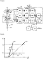
FIG. 4 is a block diagram illustrating a configuration of a signal processing circuit ofFIG. 3 ; -
FIG. 5 is a schematic diagram illustrating a relationship between coefficients in multiplication parts ofFIG. 4 ; and -
FIG. 6 is a block diagram illustrating a configuration of a measuring probe according to a second embodiment of the present invention. - 0017 An example of an embodiment of the present invention will be described below in detail with reference to the drawings.
- 0018 The first embodiment of a measuring system of the present invention will be described with reference to
FIGS. 1 to 5 . - 0019 The general configuration of a
measuring system 100 will be described first. - 0020 As illustrated in
FIG. 1 , themeasuring system 100 includes: acoordinate measuring machine 200 that moves ameasuring probe 300; an operation part 110 having manually-operatedjoysticks 111; and amotion controller 500 that controls operations of thecoordinate measuring machine 200. Themeasuring system 100 also includes : ahost computer 600 that operates thecoordinate measuring machine 200 via themotion controller 500 and processes measured data obtained by thecoordinate measuring machine 200 to determine, for example, the dimensions and shape of an object W to be measured; aninput unit 120 for inputting, for example, measurement conditions; and anoutput unit 130 for outputting a result of measurement. - 0021 As illustrated in
FIG. 1 , thecoordinate measuring machine 200 includes: themeasuring probe 300; asurface plate 210; adrive mechanism 220 provided to stand on thesurface plate 210, for three-dimensionally moving themeasuring probe 300; and a drive sensor that detects a drive amount of thedrive mechanism 220. - 0022 The general configuration of the
measuring probe 300 will be described next. - 0023 As illustrated in
FIG. 2 , themeasuring probe 300 includes: astylus 336 having acontact part 362 to be brought into contact with the object W to be measured; aprobe housing 306 capable of supporting thestylus 336 on an axial center O;detection elements 325 capable of detecting a movement of thecontact part 362 from the axial center O and a movement of thecontact part 362 on the axial center O; and asignal processing circuit 320 that processes the outputs of thedetection elements 325 to output a touch signal Sout (i.e. , themeasuring probe 300 is configured as a touch signal probe). Note that thestylus 336 is included in astylus module 304, and theprobe housing 306 and thedetection elements 325 are included in a probemain body 302. The probemain body 302 is supported by aspindle 224 of thedrive mechanism 220. Thestylus module 304 is coupled to the probemain body 302 with a kinematic joint (to be described later) in such a manner that thestylus module 304 can be detached from and attached to the probemain body 302 with high positional reproducibility. - 0024 The
measuring probe 300 will be described below in detail. Note that the longitudinal direction on the plane of paper inFIG. 2 is defined as a Z direction, the horizontal direction on the plane of paper is defined as an X direction, and the direction perpendicular to the plane of paper is defined as a Y direction for the purpose of the following description. Therefore, the direction of the axial center O of the measuring probe 300 (axial direction O) coincides with the Z direction. - 0025 As illustrated in
FIG. 2 , the probemain body 302 includes theprobe housing 306, asignal processing circuit 320, supportingmembers detection elements 325, acoupling shaft 326, aflange member 328, apermanent magnet 330, andballs 332. - 0026 As illustrated in
FIG. 2 , theprobe housing 306 includes anattachment part 308, acircuit placement part 310, afixing member 314, a bottom member (wall member) 316, and amain body cover 318. - 0027 As illustrated in
FIG. 2 , theattachment part 308 is a part to be attached to thespindle 224 at the upper end of themeasuring probe 300. Theattachment part 308 is provided with, for example, a head to be inserted into a fitting part provided in thespindle 224. Theattachment part 308 serves also as one connection terminal capable of electrically connecting to themotion controller 500. Theother connection terminal 309 is provided on the axial center O of theattachment part 308. Theattachment part 308 and theconnection terminal 309 are connected to thesignal processing circuit 320 disposed in thecircuit placement part 310 without developing a short circuit with each other by insulating members Mi1 to Mi3. Thecircuit placement part 310 is disposed at the lower end of theattachment part 308. Thecircuit placement part 310 has a generally triangular cross section, which is perpendicular to the axial center O, except for a disk-shapedupper end part 310A and a disk-shapedlower flange 312 provided at the lower end thereof. Thesignal processing circuit 320 is disposed along the generally triangular outer periphery of thecircuit placement part 310. Thecircuit placement part 310 is disposed above the supportingmembers circuit placement part 310 is disposed on the side opposite to thestylus module 304 with respect to the supportingmembers circuit placement part 310. Thus, thecircuit placement part 310 can be shaped with high stiffness. Thecircuit placement part 310 can be formed from a low-expansion material in order to reduce expansion and contraction due to heat generated from thesignal processing circuit 320. - 0028 As illustrated in
FIG. 2 , thefixing member 314 is fixed to a lower endperipheral part 312B of thelower flange 312 via the supportingmember 322. The fixingmember 314 has a cylindrical shape provided with anopening 314A on the axial center O. Note that facingparts peripheral part 312B in thelower flange 312 and on the upper end side of the inner circumference of the fixingmember 314, respectively. The facingparts member 322 without contact. A distance between the facingparts member 322 is determined so that a displacement of the supportingmember 322 is regulated to fall within the range of elastic deformation. - 0029 Four recesses 314C are provided on a lower end inner surface of the fixing
member 314 with fourfold symmetry. Thebottom member 316 is fixed to a lower end peripheral part of the fixingmember 314 via the supportingmember 324 interposed therebetween. Thebottom member 316 has an annular shape. Themain body cover 318 has a cylindrical shape. Themain body cover 318 is disposed over the outer peripheries of thecircuit placement part 310, thelower flange 312, the fixingmember 314, and thebottom member 316, so as to cover the whole of thesignal processing circuit 320. Themain body cover 318 is fixed to the fixingmember 314 with bolts. - 0030 As illustrated in
FIG. 4 , thesignal processing circuit 320 is a circuit that processes the outputs of thedetection elements 325 and outputs a touch signal (contact sensed signal) Sout for notifying that the object W to be measured has been in contact with thecontact part 362. In brief, thesignal processing circuit 320 is configured to obtain deflection amounts in the three X, Y, and Z directions from the outputs of the fourdetection elements 325, combine the deflection amounts in the three directions, and output the touch signal Sout when thecontact part 362 has a certain displacement or greater (the specific configuration will be described later). Note that thesignal processing circuit 320 may be provided with a temperature sensor so that a measurement error of the measuringprobe 300 generated due to heat is corrected in accordance with the output of the temperature sensor. - 0031 As illustrated in
FIG. 2 , the supportingmembers probe housing 306 that allow for attitude changes of thestylus 336. A stainless steel material, for example, may be used (other materials may be used) for the supportingmembers members FIG. 3 . These four arm parts are formed on the same plane. The supportingmembers members members member 324 in which thedetection elements 325 are disposed will be described below and a description overlapping with that for the supportingmember 322 will be omitted. Note that the structures of the supporting members are not limited to the shapes illustrated in the present embodiment. - 0032 As illustrated in
FIG. 3 , the supportingmember 324 is a generally circular plate-shaped member including, in addition torectangular arm parts 324B, acentral part 324A connected to thecoupling shaft 326, and a peripheral part 324C coupled to thecentral part 324A with thearm parts 324B and connected to theprobe housing 306. The peripheral part 324C is positioned in the outermost portion of the supportingmember 324. Thearm parts 324B extend linearly in a radial direction, and are disposed on the inner side of the peripheral part 324C. Thecentral part 324A is disposed on the further inner side of thearm parts 324B. The supportingmember 324 is configured such that thecentral part 324A moves vertically and horizontally by a displacement of thecoupling shaft 326 with respect to theprobe housing 306 and thearm parts 324B elastically deform accordingly. - 0033 As illustrated in
FIG. 3 , thedetection element 325 is an affixed type strain gauge, for example, for detecting a strain amount of the supportingmember 324 in which thedetection element 325 is disposed. Thedetection elements 325 are disposed on, and fixed to, for example, with an adhesive, therespective arm parts 324B of the supportingmember 324. - 0034 As illustrated in
FIGS. 2 and3 , thecoupling shaft 326 has a generally cylindrical shape and couples the two supportingmembers coupling shaft 326 is held on the axial center O by the two supportingmembers lower flange 312, the fixingmember 314, and thebottom member 316. Thecoupling shaft 326 integrally supports theflange member 328. - 0035 As illustrated in
FIG. 2 , theflange member 328 has a generally disk shape. Theflange member 328 faces thebottom member 316 in the axial direction O without contact and faces themain body cover 318 in the radial direction without contact. Theflange member 328 supports thestylus module 304. Here, a viscous material VM, such as a grease oil, is filled in at least part of a gap between thebottom member 316 and theflange member 328. This allows at least the viscous material VM to damp a displacement of theflange member 328 with respect to thebottom member 316. Thus, the occurrence of unwanted vibrations in the XY direction and the Z direction generated along with a movement of the measuringprobe 300 can be reduced, thereby preventing an increase in noise associated with an increase in sensitivity of the measuringprobe 300. Note that rubber (an elastic material) such as silicone may be used instead of the viscous material VM. Thepermanent magnet 330 is fixed to the lower surface of theflange member 328 on the axial center O. The threeballs 332 are disposed with rotational symmetry at intervals of 120 degrees in the circumferential direction on a lower end periphery of theflange member 328 so as to surround thepermanent magnet 330. - 0036 As illustrated in
FIG. 2 , theaforementioned stylus module 304 includes anover-travel mechanism 334 and thestylus 336 supported by theover-travel mechanism 334. - 0037 As illustrated in
FIG. 2 , theover-travel mechanism 334 is a mechanism that changes the position of thestylus 336 when a force larger than a measuring force F upon outputting the touch signal Sout is applied to thestylus 336 and restores the position of thestylus 336 automatically when such a large force disappears. In other words, theover-travel mechanism 334 works to change the position of thestylus 336 upon the application of a large force to thestylus 336 before thestylus module 304 comes off from the probemain body 302. Specifically, theover-travel mechanism 334 includes aflange part 338, anextended part 344, astylus holder 346, and acoil spring 350. - 0038 As illustrated in
FIG. 2 , theflange part 338 is a member corresponding to theflange member 328. More specifically, theflange part 338 is provided with three V-grooves 340 at intervals of 120 degrees in the circumferential direction of theflange part 338 so as to be in contact with theballs 332. A magnetic member (which may be a permanent magnet) 342 attracted to thepermanent magnet 330 is disposed in theflange part 338 so as to face thepermanent magnet 330. - 0039 Here, the V-
grooves 340 are each to be in contact with the surface of thecorresponding ball 332 as illustrated inFIG. 2 . Thus, when thepermanent magnet 330 and themagnetic member 342 are being attracted to each other by a predetermined magnetic force, theflange part 338 is seated on (in contact with) theflange member 328 at six points. In other words, theflange member 328 and theflange part 338 can be coupled to each other while achieving high positioning accuracy. More specifically, theflange part 338 and theflange member 328 constitute a kinematic joint (referred to also as a kinematic coupling; the same applies hereinafter), which is a coupling mechanism wherein they can be detached from and attached to each other. This kinematic joint allows for the achievement of high positioning reproducibility even when the probemain body 302 and thestylus module 304 are repeatedly detached from and attached to each other. Note that the kinematic joint is not limited to the combination of the V-groove and the ball, but may be a combination of a pair of rollers and a ball. Alternatively, the combination of the V-groove and the ball with the opposite arrangement may be employed. In other words, the kinematic joint is not limited to the combination of the V-groove and the ball as long as the six-point seating can be achieved (the same applies to the following kinematic joint). Note that thestylus module 304 can drop off from the flange member 328 (including not only a case when theballs 332 are not in contact with all of the V-grooves 340 but also a case when only part of theballs 332 is not in contact with the V-grooves 340; the same applies hereinafter) when a large force is applied to thestylus 336 from the lateral direction (the direction perpendicular to the axial direction O), thereby preventing the breakage of the probe main body 302 (thus, the predetermined magnetic force by which thepermanent magnet 330 and themagnetic member 342 are attracted to each other is a force corresponding to the aforementioned large force; the same applies hereinafter). - 0040 As illustrated in
FIG. 2 , theextended part 344 is formed integrally with the outer periphery of theflange part 338. Theextended part 344 houses thecoil spring 350 capable of expanding and contracting in the axial direction O therein. Thestylus holder 346 is provided at an end of theextended part 344 in the axial direction O. Thestylus holder 346 is connected to theextended part 344 with bolts. The upper surface of thestylus holder 346 closer to thecoil spring 350 movably supports theflange part 356 of thestylus 336 pressed by thecoil spring 350. Threeballs 348 are disposed on the upper surface of thestylus holder 346 closer to thecoil spring 350 at intervals of 120 degrees in the circumferential direction thereof. Three V-grooves 358 are provided on the lower surface of theflange part 356 at intervals of 120 degrees in the circumferential direction thereof so as to correspond to theballs 348. Note that an axial direction of the V-groove 358 is approximately the same as the radial direction toward the axial center O. In other words, it can be said that thestylus holder 346 and theflange part 356 constitute the aforementioned kinematic joint. - 0041 Thus, when the
flange part 356 is being pressed by thecoil spring 350 with a predetermined spring force, theflange part 356 is seated on (in contact with) thestylus holder 346 at six points. This allows for positioning at the fixed position. In other words, theover-travel mechanism 334 can achieve the highly-reproducible positioning of thestylus 336 with respect to theflange part 338 within a range of the measuring force F not greater than the pressing force of thecoil spring 350. When a force larger than the predetermined spring force given by thecoil spring 350 is applied to thestylus 336, theflange part 356 can be removed off from thestylus holder 346, thereby preventing the dropping off of thestylus module 304 from the probemain body 302. While the facingparts member 322 to fall within the range of elastic deformation, the predetermined spring force given by thecoil spring 350 is preferably set smaller than the measuring force F exceeding the range of elastic deformation of the supportingmembers - 0042 As illustrated in
FIG. 2 , thestylus 336 includes: theflange part 356 supported by thestylus holder 346 as described above; arod part 360 extending from theflange part 356 in the axial direction O; and thecontact part 362 provided at the tip of therod part 360. - 0043 As illustrated in
FIG. 2 , the base end of therod part 360 is attached to theflange part 356. The tip of therod part 360 is provided with thespherical contact part 362 to be brought into contact with the object W to be measured (i.e., thestylus 336 includes thecontact part 362 to be brought into contact with the object W to be measured). Note that when no displacement of thestylus 336 in the XY direction occurs, the direction of the central axis of thestylus 336 coincides with the Z direction (the axial direction O). - 0044 Next, the
signal processing circuit 320 will be described next with reference toFIGS. 3 and4 . - 0045 As illustrated in
FIG. 3 , thesignal processing circuit 320 includes afirst processing part 364, asecond processing part 366, a referencevalue setting part 376, and acomparison part 378. - 0046 As illustrated in
FIG. 3 , thefirst processing part 364 processes the outputs of thedetection elements 325 to output three displacement signals Vx, Vy, and Vz representing displacement components of thecontact part 362 in the mutually perpendicular three X, Y, and Z directions, respectively. Specifically, thefirst processing part 364 includessubtraction parts FIG. 4 . From the outputs of the twodetection elements 325 at positions different from each other by an angle of 90 degrees around the axial center O, thesubtraction parts detection elements 325 at positions different from the aforementioned twodetection elements 325 by an angle of 180 degrees (in the X direction and in the Y direction), respectively. Thesubtraction parts addition part 364Z adds all of the four outputs from the fourdetection elements 325. Theaddition part 364Z then outputs the displacement signal Vz. - 0047 As illustrated in
FIG. 3 , thesecond processing part 366 outputs a composite signal Vout obtained by combining the three displacement signals Vx, Vy, and Vz. Specifically, thesecond processing part 366 includes: threemultiplication parts parts root operation part 374, as illustrated inFIG. 4 . The threemultiplication parts contact part 362 in the three X, Y, and Z directions when the composite signal Vout reaches the second reference value Vs2 from the first reference value Vs1. In other words, this calibration makes the amounts of displacement of thecontact part 362 identical with one another in the three X, Y, and Z directions when the composite signal Vout is changed from the first reference value Vs1 to the second reference value Vs2. Note that all of the predetermined coefficients Kx, Ky, and Kz may be the same, two of the predetermined coefficients Kx, Ky, and Kz may be the same, or the predetermined coefficients Kx, Ky, and Kz may be different from one another. - 0048 Specifically, the relation between the X direction and the Z direction of the
contact part 362 for the predetermined coefficients Kx, Kz will be described with reference toFIG. 5 (a description about the Y direction will be omitted because of its similarity to the X direction). InFIG. 5 , the vertical axis represents the predetermined reference value Vs, and the horizontal axis represents a displacement Dp of thecontact part 362.FIG. 5 is a graph with a solid line Zax showing a displacement of thecontact part 362 in the Z direction and with a broken line Xax showing a displacement of thecontact part 362 in the X direction. For example, a Z-direction displacement amount ΔZ and an X-direction displacement amount ΔX of thecontact part 362 from the first reference value Vs1 to the second reference value Vs2, and the predetermined coefficients Kz and Kx satisfy the relationship as expressed by Expression (1).
- 0050 Note that a plurality of
styluses 336, which can be detached from and attached to thestylus module 304, are prepared, and the predetermined coefficients Kx, Ky, and Kz are changed for each of thestyluses 336. The predetermined coefficients Kx, Ky, and Kz are obtained when a reference sphere (may be not a reference sphere but the object W to be measured itself) provided on thesurface plate 210 is measured by the measuringprobe 300, for example. The predetermined coefficients Kx, Ky, and Kz are then stored in a storage part (the storage part may be provided in thesignal processing circuit 320, themotion controller 500, or the host computer 600). Needless to say, the predetermined coefficients Kx, Ky, and Kz may be stored in the storage part before measuring the reference sphere. - 0051 As illustrated in
FIG. 4 , the three squaringparts multiplication parts addition part 372 adds all of squared signals Vsx, Vsy, and Vsz outputted from the squaringparts root operation part 374 calculates the square root of the output of theaddition part 372 to output the composite signal Vout. - 0052 As illustrated in
FIG. 3 , the referencevalue setting part 376 is a part that sets the predetermined reference value Vs. For example, the predetermined reference value Vs may be set via theinput unit 120, or may be set on the basis of a value stored in the storage part of thehost computer 600. - 0053 As illustrated in
FIG. 3 , thecomparison part 378 compares the signal level of the composite signal Vout with the predetermined reference value Vs, binarizes the comparison result of the composite signal Vout, and outputs the binarized value. More specifically, thecomparison part 378 outputs the touch signal Sout, which is a HIGH signal, when the signal level of the composite signal Vout is higher than or equal to the predetermined reference value Vs. Note that the circuit for the signal processing up to the composite signal Vout may be either an analog signal processing circuit or a digital signal processing circuit. - 0054 As described above, since the
detection elements 325 are disposed with fourfold symmetry in the present embodiment, the outputs of thedetection elements 325 disposed on thearm parts 324B can be easily calculated into displacement components in the three X, Y, and Z directions. At the same time, measurement sensitivity can be made isotropic around the axial center O. Note that the present invention is not limited thereto. The arm part may have an integral circular plate shape without being separated into four. Alternatively, a supporting member with a rotationally symmetric shape including arm parts in a multiple of four (for example, eight arm parts without being limited to four) may be employed. Alternatively, not two but three or more supporting members may be employed. Note that the supporting member without the detection elements does not necessarily need to include the arm parts in a multiple of four. Alternatively, two or more supporting members, each supporting the detection elements, may be employed. - 0055 Specifically, the
first processing part 364 includes thesubtraction parts addition part 364Z, and thesecond processing part 366 includes the squaringparts addition part 372 in the present embodiment. This allows thesignal processing circuit 320 to output the touch signal Sout with the simple configuration. Without being limited thereto, the first processing part and the second processing part may have different configurations. - 0056 In the present embodiment, the
second processing part 366 further includes the square-root operation part 374. Consequently, the predetermined reference value Vs in thecomparison part 378 can be assumed to be in the same dimension as the displacement amounts of thecontact part 362. Thus, the predetermined reference value Vs can be set easily. Without being limited thereto, no square-root operation part may be provided. - 0057 In the present embodiment, the
second processing part 366 further includes themultiplication parts contact part 362 when the touch signal Sout is outputted. Thus, isotropic sensitivity can be achieved in the three X, Y, and Z directions. Note that the present invention is not limited thereto. Only part of the multiplication parts may be provided or no multiplication parts may be provided. The multiplication parts may not necessarily achieve isotropic sensitivity in the three X, Y, and Z directions. - 0058 Furthermore, the predetermined coefficients Kx, Ky, and Kz are set in the present embodiment, when the first reference value Vs1 and the second reference value Vs2 are respectively set as the predetermined reference values Vs, so as to calibrate differences among the displacement amounts of the
contact part 362 in the three X, Y, and Z directions when the composite signal Vout reaches the second reference value Vs2 from the first reference value Vs1. Thus, the use of such predetermined coefficients Kx, Ky, and Kz allows the touch signal Sout to be outputted with a constant displacement amount in all of the three X, Y, and Z directions. Without being limited thereto, the predetermined coefficients Kx, Ky, and Kz may be determined by a different method. - 0059 In the present embodiment, the plurality of
styluses 336 is prepared, and the predetermined coefficients Kx, Ky, and Kz are changed for each of thestyluses 336. Thus, when a different stylus 336 (including its length) is used, the characteristics thereof can be corrected, thereby allowing for measurement with high sensitivity. Note that the present invention is not limited thereto. The predetermined coefficients Kx, Ky, and Kz may not necessarily be changed even when a plurality of styluses is prepared. - 0060 In the present embodiment, the
detection element 325 is an affixed type strain gauge. In other words, a highly-sensitive and low-cost detection element can be used as thedetection element 325. Moreover, the position at which thedetection element 325 is affixed can be easily adjusted. Thedetection element 325 does not detect a transient impact force only but can send an output corresponding to the deflection amount stably for a certain period of time. This can eliminate a need to provide a circuit for performing delay time adjustments even if output timing for the deflection amounts in the three X, Y, and Z directions is shifted from one another in thedetection elements 325. Without being limited thereto, the detection element may be a strain gauge or PZT, for example, formed on the arm part by means of direct deposition, for example. - 0061 In other words, according to the present embodiment, the measurement directional dependency of sensitivity can be reduced with the simple configuration while maintaining high sensitivity.
- 0062 While the present invention has been described taking the first embodiment as an example, the present invention is not limited to the first embodiment. In other words, modifications and design alterations are obviously possible without departing from the scope of the present invention.
- 0063 For example, the output of the
second processing part 366 is directly compared with the predetermined reference value Vs in thecomparison part 378 in the first embodiment. However, the present invention is not limited thereto. For example, the present invention may be configured as in the second embodiment illustrated inFIG. 6 . The second embodiment is different from the first embodiment only in that a filter part is provided between a second processing part and a comparison part in a signal processing circuit. Accordingly, only the first digit of the reference numerals of elements excluding those relating to the filter part is basically changed and the description about those elements will be omitted. - 0064 As illustrated in
FIG. 6 , asignal processing circuit 420 includes afilter part 475 in the second embodiment. A low-pass filter, a high-pass filter, or a band-pass filter may be set in thefilter part 475. The low-pass filter can effectively eliminate the effects of noise due to disturbance vibration, electrical noise, and probe vibration due to the movement of the probe. The high-pass filter can eliminate an effect such as the one which causes the output of adetection element 425 to fluctuate gently due to an influence of temperature, for example, and the effect of noise close to a DC component generated by the attitude (for example, horizontal attitude) of the measuringprobe 300. The band-pass filter can eliminate the effects of the aforementioned ranges. The filter part is not limited thereto as long as the filter part is provided in the preceding stage of the comparison part. - 0065 In the first embodiment, such a correction as to eliminate the directional dependency can be made when the touch signal Sout is outputted. However, no particular consideration is made for the directional dependency of the measuring force F upon outputting the touch signal Sout. In view of this, the signal processing circuit may be configured, for example, to output the touch signal Sout, when a certain amount of displacement and a certain amount of measuring force F are applied in an arbitrary direction, to the contact part in the reference position that is not applied with the measuring force F. In such a case, the force sensitivity of the contact part can be made uniform in all directions, thus allowing for an increase in measurement accuracy. A correction coefficient for such a purpose may be obtained, for example, when the reference sphere provided on the surface plate is measured by the measuring probe, and may be stored in the storage part (the storage part may be provided in the signal processing circuit, the motion controller, or the host computer). Needless to say, such a correction coefficient may be stored in the storage part before measuring the reference sphere.
- 0066 In the first embodiment, no consideration is made for a case in which the axis of the
stylus 336 and the axis of thecoupling shaft 326 do not overlap each other on the same straight line even when the touch signal Sout is outputted. In other words, no bend of thestylus 336 is taken into consideration. However, the present invention is not limited thereto. For example, the signal processing circuit may be configured to correct a displacement amount in the direction perpendicular to the axial direction O in accordance with a deflection amount of the stylus, when the contact part is applied with the measuring force F in the direction perpendicular to the axial direction O. In this case, the deflection amount under the application of the measuring force F can also be corrected in the measuring probe. Consequently, the touch signal Sout can be outputted with smaller directional dependency. The correction coefficient for such a purpose can be similarly obtained, for example, when the reference sphere provided on the surface plate is measured by the measuring probe, and may be stored in the storage part (the storage part may be provided in the signal processing circuit, the motion controller, or the host computer). Needless to say, such a correction coefficient may be stored in the storage part before measuring the reference sphere (it may be the object W to be measured itself). 0067 - While the signal processing circuit includes the first processing part and the second processing part in the above-described embodiment, the present invention is not limited thereto. For example, without providing the second processing part in the signal processing circuit, the displacement signals Vx, Vy, and Vz, which are the outputs of the first processing part, may be directly outputted from the signal processing circuit. In other words, the measuring probe may be not the touch signal probe described in the above-described embodiment but a scanning probe. Even when the measuring probe is configured as a scanning probe, only the multiplication parts of the second processing part may be provided and the displacement output signals Vax, Vay, and Vaz may be outputted from the signal processing circuit. Alternatively, even when the measuring probe is configured as a touch signal probe, the touch signal Sout and the displacement output signals Vax, Vay, and Vaz indicated by broken lines may be outputted from the signal processing circuit as in
FIG. 4 illustrating the above-described embodiment. - 0068 The present invention can be applied to a wide range of measuring probes used for measuring three-dimensional shapes of objects to be measured. In doing so, the present invention can be applied not only to measuring probes for coordinate measuring machines but also to measuring probes used in machine tools.
Claims (9)
- A measuring probe(300) comprising:a stylus(336, 436) having a contact part(362, 462) to be brought into contact with an object to be measured;a probe housing(306) capable of supporting the stylus(336, 436) on an axial center(O);detection elements (325, 425) capable of detecting a movement of the contact part(362, 462);a signal processing circuit (320, 420) that processes outputs of the detection elements(325, 425); anda plurality of supporting members (322, 324, 422, 424) in an axial direction(O) of the probe housing(306), the supporting member(322, 324, 422, 424) having a rotationally symmetric shape and allowing for an attitude change of the stylus (336, 436), whereinfour said detection elements(325, 425) are disposed at fourfold symmetric positions in at least one of the plurality of supporting members (322, 324, 422, 424) that includes a deformable arm part(324B), andthe signal processing circuit(320, 420) includes a first processing part(364, 464) that processes the outputs of the detection elements(325, 425) to output three displacement signals(Vx, Vy, Vz) representing displacement components of the contact part(362, 462) in mutually perpendicular three directions, respectively.
- The measuring probe(300) according to claim 1, wherein
the signal processing circuit(320, 420) further includes: a second processing part(366, 466) that outputs a composite signal(Vout) obtained by combining the three displacement signals (Vx, Vy, Vz) ; and a comparison part (378, 478) that compares a signal level of the composite signal(Vout) with a predetermined reference value(Vs), and
the signal processing circuit(320, 420) outputs a touch signal(Sout) when the signal level of the composite signal(Vout) is higher than or equal to the predetermined reference value (Vs) . - The measuring probe(300) according to claim 2, wherein
the first processing part(364, 464) includes: a first addition part(364Z) that adds all of four outputs from the four detection elements(325, 425); and subtraction parts(364X, 364Y) that subtract, from outputs of two of the detection elements (325, 425) at positions different from each other by an angle of 90 degrees around the axial center (O), outputs of the detection elements (325, 425) at positions different from the two of the detection elements(325, 425) by an angle of 180 degrees, respectively, and
the second processing part(366, 466) include: squaring parts(370X, 370Y, 370Z) that square the three displacement signals(Vx, Vy, Vz, Vax, Vay, Vaz), respectively; and a second addition part (372) that adds all of squared signals (Vsx, Vsy, Vsz) outputted from the squaring parts(370X, 370Y, 370Z). - The measuring probe(300) according to claim 3, wherein the second processing part(366, 466) further includes a square-root operation part(374) that calculates square root of an output of the second addition part(372) to output the composite signal(Vout).
- The measuring probe(300) according to any one of claims 2 to 4, wherein the second processing part further includes multiplication parts (368X, 368Y, 368Z) that multiply signal levels of the three displacement signals(Vx, Vy, Vz) by predetermined coefficients(Kx, Ky, Kz), respectively.
- The measuring probe(300) according to claim 5, wherein the predetermined coefficients (Kx, Ky, Kz) are respectively set, when a first reference value(Vs1) and a second reference value(Vs2) are set as the predetermined reference values(Vs), so as to calibrate differences among displacement amounts of the contact part(362, 462) in the three directions when the composite signal (Vout) reaches the second reference value (Vs2) from the first reference value(Vs1).
- The measuring probe according to any one of claims 2 to 6, wherein the signal processing circuit(420) includes any of a low-pass filter, a high-pass filter, and a band-pass filter in a preceding stage of the comparison part(478).
- The measuring probe(300) according to any one of claims 2 to 7, wherein the signal processing circuit (320, 420) is configured to output the touch signal (Sout), when a certain amount of displacement and a certain amount of measuring force(F) are applied in an arbitrary direction, to the contact part(362, 462) in a reference position that is not applied with the measuring force(F).
- The measuring probe(300) according to any one of claims 1 to 8, wherein the signal processing circuit (320, 420) is further configured to correct a displacement amount in a direction perpendicular to the axial direction(O) in accordance with a deflection amount of the stylus (336, 436), when the contact part (362, 462) is applied with a measuring force(F) in the direction perpendicular to the axial direction(O).
Applications Claiming Priority (1)
| Application Number | Priority Date | Filing Date | Title |
|---|---|---|---|
| JP2016036473A JP6212148B2 (en) | 2016-02-26 | 2016-02-26 | Measuring probe |
Publications (2)
| Publication Number | Publication Date |
|---|---|
| EP3211361A1 true EP3211361A1 (en) | 2017-08-30 |
| EP3211361B1 EP3211361B1 (en) | 2018-04-11 |
Family
ID=58158916
Family Applications (1)
| Application Number | Title | Priority Date | Filing Date |
|---|---|---|---|
| EP17157600.2A Active EP3211361B1 (en) | 2016-02-26 | 2017-02-23 | Measuring probe |
Country Status (4)
| Country | Link |
|---|---|
| US (1) | US10415949B2 (en) |
| EP (1) | EP3211361B1 (en) |
| JP (1) | JP6212148B2 (en) |
| CN (1) | CN107131853B (en) |
Families Citing this family (15)
| Publication number | Priority date | Publication date | Assignee | Title |
|---|---|---|---|---|
| JP6484108B2 (en) * | 2015-05-22 | 2019-03-13 | 株式会社ミツトヨ | Method for controlling shape measuring apparatus |
| WO2017182875A1 (en) * | 2016-04-21 | 2017-10-26 | Mitutoyo Corporation | Coordinate measurement probe body |
| JP6341962B2 (en) | 2016-08-26 | 2018-06-13 | 株式会社ミツトヨ | Three-dimensional measuring apparatus and coordinate correction method |
| JP6295299B2 (en) | 2016-08-26 | 2018-03-14 | 株式会社ミツトヨ | Coordinate correction method and three-dimensional measuring apparatus |
| JP2018031754A (en) | 2016-08-26 | 2018-03-01 | 株式会社ミツトヨ | Three-dimensional measurement device and coordinate correction method |
| CN110118515B (en) * | 2018-02-06 | 2020-12-08 | 清华大学深圳研究生院 | A method and device for verifying the precision of a surgical needle |
| CN108895953B (en) * | 2018-05-11 | 2020-08-21 | 深圳清华大学研究院 | Contact type measuring head, three-coordinate measuring machine and tool setting gauge |
| JP6738883B2 (en) * | 2018-11-28 | 2020-08-12 | 株式会社ミツトヨ | Probe unit and measurement system |
| JP6898966B2 (en) * | 2019-06-07 | 2021-07-07 | 株式会社ミツトヨ | Defect judgment unit |
| JP7530272B2 (en) * | 2020-11-06 | 2024-08-07 | 株式会社ミツトヨ | Shape measuring device and abnormality detection method |
| US11644299B2 (en) * | 2020-12-31 | 2023-05-09 | Mitutoyo Corporation | Inductive position sensor signal gain control for coordinate measuring machine probe |
| US11733021B2 (en) | 2021-12-22 | 2023-08-22 | Mitutoyo Corporation | Modular configuration for coordinate measuring machine probe |
| US12188765B2 (en) | 2022-09-07 | 2025-01-07 | Mitutoyo Corporation | Adjustable update rate for measuring probe |
| US12287194B2 (en) * | 2022-11-29 | 2025-04-29 | Mitutoyo Corporation | Motion mechanism for measuring probe |
| US12488448B2 (en) | 2023-07-20 | 2025-12-02 | Mitutoyo Corporation | Machine vision system with objective lens and collision protection |
Citations (4)
| Publication number | Priority date | Publication date | Assignee | Title |
|---|---|---|---|---|
| US5345689A (en) * | 1991-05-25 | 1994-09-13 | Renishaw Metrology Limited | Measuring probe |
| JPH09507918A (en) | 1994-11-17 | 1997-08-12 | レニショウ パブリック リミテッド カンパニー | Contact probe |
| DE10122200A1 (en) * | 2001-05-08 | 2002-11-14 | Zeiss Carl | Probe for a coordinate measuring machine. Coordinate measuring device, calibration body for a coordinate measuring device and method for calibrating a coordinate measuring device |
| US20040118000A1 (en) * | 2001-02-23 | 2004-06-24 | Roland Roth | Coordinate measuring apparatus for contacting a workpiece, touch probe for a coordinate measuring apparatus and method of operating a coordinate measuring apparatus |
Family Cites Families (49)
| Publication number | Priority date | Publication date | Assignee | Title |
|---|---|---|---|---|
| US4158919A (en) * | 1976-03-24 | 1979-06-26 | Rolls-Royce Limited | Apparatus for measuring displacement in at least two orthogonal dimensions |
| US4866854A (en) * | 1986-12-05 | 1989-09-19 | The Charles Stark Draper Laboratory, Inc. | Multiple axis displacement sensor |
| JPH04178509A (en) * | 1990-11-13 | 1992-06-25 | Tokyo Seimitsu Co Ltd | Measurement method for coordinate measuring machine |
| EP0521703B1 (en) * | 1991-07-03 | 1995-11-02 | Renishaw Metrology Limited | Signal processing circuit for trigger probe |
| US5210410A (en) * | 1991-09-26 | 1993-05-11 | The Board Of Trustees Of The Leland Stanford Junior University | Scanning probe microscope having scan correction |
| DE4204602A1 (en) * | 1992-02-15 | 1993-08-19 | Zeiss Carl Fa | METHOD FOR MEASURING COORDINATES ON WORKPIECES |
| JP2587565B2 (en) * | 1992-05-28 | 1997-03-05 | 株式会社ミツトヨ | Copying probe |
| DE69323289T3 (en) * | 1992-12-24 | 2003-04-24 | Renishaw Plc, Wotton-Under-Edge | Probe and signal processing circuit therefor |
| DE4325744C1 (en) * | 1993-07-31 | 1994-12-15 | Heidenhain Gmbh Dr Johannes | Multicoordinate probe |
| JP3075981B2 (en) * | 1996-04-05 | 2000-08-14 | 松下電器産業株式会社 | Shape measuring device |
| US5822877A (en) * | 1996-06-20 | 1998-10-20 | Brown & Sharpe Manufacturing Company | Multi-probe system for dimensional metrology |
| US6044569A (en) * | 1997-02-10 | 2000-04-04 | Mitutoyo Corporation | Measuring method and measuring instrument |
| JP3285320B2 (en) | 1997-02-17 | 2002-05-27 | 株式会社ミツトヨ | Touch signal probe |
| US6131301A (en) * | 1997-07-18 | 2000-10-17 | Renishaw Plc | Method of and apparatus for measuring workpieces using a coordinate positioning machine |
| GB2336433B (en) * | 1998-04-14 | 2002-02-06 | Mitutoyo Corp | Touch signal probe |
| JP3130289B2 (en) * | 1998-08-04 | 2001-01-31 | 株式会社ミツトヨ | Touch signal probe |
| GB2348706B (en) * | 1999-04-02 | 2003-09-24 | Mitutoyo Corp | Movement control mechanism of contact-type vibrating probe |
| JP3819250B2 (en) * | 2000-05-15 | 2006-09-06 | 株式会社ミツトヨ | Excitation contact detection sensor |
| JP3500125B2 (en) * | 2001-02-14 | 2004-02-23 | 株式会社ミツトヨ | Elastic body vibration detection system |
| JP3820357B2 (en) * | 2001-08-07 | 2006-09-13 | 株式会社ミツトヨ | Measuring method and measuring apparatus |
| JP2003065748A (en) * | 2001-08-29 | 2003-03-05 | Mitsutoyo Corp | Measuring device |
| JP3961258B2 (en) * | 2001-10-10 | 2007-08-22 | 株式会社ミツトヨ | Touch sensor and probe for fine shape measuring device |
| US6895359B2 (en) * | 2002-11-25 | 2005-05-17 | Mitutoyo Corporation | Workpiece coordinate system origin setting method, workpiece coordinate system origin setting program and workpiece coordinate system origin setting device of a surface property measuring machine |
| GB0228368D0 (en) * | 2002-12-05 | 2003-01-08 | Renishaw Plc | Probe for high speed scanning |
| GB2417090A (en) * | 2003-04-28 | 2006-02-15 | Stephen James Crampton | CMM arm with exoskeleton |
| JP4330388B2 (en) * | 2003-07-28 | 2009-09-16 | 株式会社ミツトヨ | Copy probe |
| JP4695374B2 (en) * | 2003-11-25 | 2011-06-08 | 株式会社ミツトヨ | Surface scanning measuring device and scanning probe correction table creation method |
| US7693325B2 (en) * | 2004-01-14 | 2010-04-06 | Hexagon Metrology, Inc. | Transprojection of geometry data |
| GB0506158D0 (en) * | 2005-03-24 | 2005-05-04 | Renishaw Plc | Measurement probe |
| JP2007040822A (en) * | 2005-08-03 | 2007-02-15 | Mitsutoyo Corp | Workpiece measuring method |
| JP4828974B2 (en) * | 2006-03-16 | 2011-11-30 | 株式会社ミツトヨ | Screw measuring method, screw measuring probe, and screw measuring device using the same |
| JP2007309684A (en) * | 2006-05-16 | 2007-11-29 | Mitsutoyo Corp | Measurement controller, surface property measuring instrument, and measurement control method |
| DK2190530T3 (en) * | 2007-09-13 | 2018-02-19 | Toby D Henderson | PATIENT POSITIONING SYSTEM |
| JP3140476U (en) | 2008-01-15 | 2008-03-27 | 株式会社ミツトヨ | Excitation contact detection sensor |
| JP5089428B2 (en) | 2008-02-21 | 2012-12-05 | 株式会社ミツトヨ | Scanning measuring device |
| GB0804467D0 (en) * | 2008-03-11 | 2008-04-16 | Renishaw Plc | Touch trigger measurement probe |
| US20110112786A1 (en) * | 2009-11-06 | 2011-05-12 | Hexagon Metrology Ab | Cmm with improved sensors |
| DE102010018250A1 (en) * | 2010-04-23 | 2011-10-27 | Carl Zeiss Industrielle Messtechnik Gmbh | Method for measuring coordinates on workpieces on a coordinate measuring machine |
| IT1402715B1 (en) * | 2010-10-29 | 2013-09-18 | Marposs Spa | PROBE PROBE |
| CN202562431U (en) * | 2012-05-24 | 2012-11-28 | 曹玉 | Micrometric displacement measurement device |
| JP6093538B2 (en) * | 2012-10-11 | 2017-03-08 | 株式会社ミツトヨ | Thread shape measurement method |
| JP5747180B2 (en) * | 2012-12-06 | 2015-07-08 | パナソニックIpマネジメント株式会社 | Shape measuring method and shape measuring apparatus |
| DE102013001457A1 (en) * | 2013-01-28 | 2014-07-31 | Blum-Novotest Gmbh | In a workpiece processing machine to be recorded temperature-compensated probe and method for temperature compensation of a probe |
| JP6189153B2 (en) * | 2013-09-18 | 2017-08-30 | 株式会社ミツトヨ | Insulator type measuring instrument |
| US9429416B2 (en) * | 2013-12-06 | 2016-08-30 | Tesa Sa | Accessory for coordinate measuring machine |
| JP6049786B2 (en) * | 2015-03-05 | 2016-12-21 | 株式会社ミツトヨ | Measuring probe |
| US9528824B2 (en) * | 2015-03-31 | 2016-12-27 | Mitutoyo Corporation | Tactile probing system |
| US9791262B2 (en) * | 2015-12-17 | 2017-10-17 | Mitutoyo Corporation | Measurement device with multiplexed position signals |
| US10145666B2 (en) * | 2016-12-19 | 2018-12-04 | Mitutoyo Corporation | Touch probe for CMM including digital signal communication |
-
2016
- 2016-02-26 JP JP2016036473A patent/JP6212148B2/en not_active Expired - Fee Related
-
2017
- 2017-02-23 US US15/440,280 patent/US10415949B2/en active Active
- 2017-02-23 EP EP17157600.2A patent/EP3211361B1/en active Active
- 2017-02-24 CN CN201710104606.3A patent/CN107131853B/en active Active
Patent Citations (4)
| Publication number | Priority date | Publication date | Assignee | Title |
|---|---|---|---|---|
| US5345689A (en) * | 1991-05-25 | 1994-09-13 | Renishaw Metrology Limited | Measuring probe |
| JPH09507918A (en) | 1994-11-17 | 1997-08-12 | レニショウ パブリック リミテッド カンパニー | Contact probe |
| US20040118000A1 (en) * | 2001-02-23 | 2004-06-24 | Roland Roth | Coordinate measuring apparatus for contacting a workpiece, touch probe for a coordinate measuring apparatus and method of operating a coordinate measuring apparatus |
| DE10122200A1 (en) * | 2001-05-08 | 2002-11-14 | Zeiss Carl | Probe for a coordinate measuring machine. Coordinate measuring device, calibration body for a coordinate measuring device and method for calibrating a coordinate measuring device |
Also Published As
| Publication number | Publication date |
|---|---|
| US20170248402A1 (en) | 2017-08-31 |
| CN107131853A (en) | 2017-09-05 |
| CN107131853B (en) | 2020-02-07 |
| US10415949B2 (en) | 2019-09-17 |
| JP6212148B2 (en) | 2017-10-11 |
| EP3211361B1 (en) | 2018-04-11 |
| JP2017151069A (en) | 2017-08-31 |
Similar Documents
| Publication | Publication Date | Title |
|---|---|---|
| EP3211361B1 (en) | Measuring probe | |
| US10393495B2 (en) | Measuring probe | |
| US11268874B2 (en) | Defect judging unit of measuring probe and defect judging method thereof | |
| JP6966471B2 (en) | Coordinate measurement probe body | |
| KR101477120B1 (en) | Capacitive 6-axial force/torque sensor | |
| CN111238433B (en) | Probe unit and measurement system | |
| US10078026B2 (en) | Multi-component force-torque sensing device with reduced cross-talk for twist-compression testing machine | |
| EP4379313A1 (en) | Motion mechanism for measuring probe | |
| US20250130032A1 (en) | A scanning probe | |
| JP2018532124A (en) | Force measuring device | |
| KR101533920B1 (en) | Capacitive 3-axial strength sensor | |
| US20240200924A1 (en) | Touch trigger probe with capacitive sensor | |
| KR100605058B1 (en) | Contact Probes for 3D Measurement | |
| Ferreira et al. | Universal characterization method for 3D tactile probing systems | |
| JP2026057388A (en) | Force sensor with dynamic error correction function, and dynamic error correction method considering base acceleration. | |
| JP2016109515A (en) | Probe head for three-dimensional coordinate measuring instrument |
Legal Events
| Date | Code | Title | Description |
|---|---|---|---|
| PUAI | Public reference made under article 153(3) epc to a published international application that has entered the european phase |
Free format text: ORIGINAL CODE: 0009012 |
|
| STAA | Information on the status of an ep patent application or granted ep patent |
Free format text: STATUS: THE APPLICATION HAS BEEN PUBLISHED |
|
| AK | Designated contracting states |
Kind code of ref document: A1 Designated state(s): AL AT BE BG CH CY CZ DE DK EE ES FI FR GB GR HR HU IE IS IT LI LT LU LV MC MK MT NL NO PL PT RO RS SE SI SK SM TR |
|
| AX | Request for extension of the european patent |
Extension state: BA ME |
|
| STAA | Information on the status of an ep patent application or granted ep patent |
Free format text: STATUS: REQUEST FOR EXAMINATION WAS MADE |
|
| 17P | Request for examination filed |
Effective date: 20171017 |
|
| RBV | Designated contracting states (corrected) |
Designated state(s): AL AT BE BG CH CY CZ DE DK EE ES FI FR GB GR HR HU IE IS IT LI LT LU LV MC MK MT NL NO PL PT RO RS SE SI SK SM TR |
|
| GRAP | Despatch of communication of intention to grant a patent |
Free format text: ORIGINAL CODE: EPIDOSNIGR1 |
|
| STAA | Information on the status of an ep patent application or granted ep patent |
Free format text: STATUS: GRANT OF PATENT IS INTENDED |
|
| INTG | Intention to grant announced |
Effective date: 20180102 |
|
| GRAS | Grant fee paid |
Free format text: ORIGINAL CODE: EPIDOSNIGR3 |
|
| GRAA | (expected) grant |
Free format text: ORIGINAL CODE: 0009210 |
|
| STAA | Information on the status of an ep patent application or granted ep patent |
Free format text: STATUS: THE PATENT HAS BEEN GRANTED |
|
| AK | Designated contracting states |
Kind code of ref document: B1 Designated state(s): AL AT BE BG CH CY CZ DE DK EE ES FI FR GB GR HR HU IE IS IT LI LT LU LV MC MK MT NL NO PL PT RO RS SE SI SK SM TR |
|
| REG | Reference to a national code |
Ref country code: GB Ref legal event code: FG4D |
|
| REG | Reference to a national code |
Ref country code: CH Ref legal event code: EP |
|
| REG | Reference to a national code |
Ref country code: AT Ref legal event code: REF Ref document number: 988515 Country of ref document: AT Kind code of ref document: T Effective date: 20180415 |
|
| REG | Reference to a national code |
Ref country code: IE Ref legal event code: FG4D |
|
| REG | Reference to a national code |
Ref country code: DE Ref legal event code: R096 Ref document number: 602017000030 Country of ref document: DE |
|
| REG | Reference to a national code |
Ref country code: NL Ref legal event code: MP Effective date: 20180411 |
|
| REG | Reference to a national code |
Ref country code: LT Ref legal event code: MG4D |
|
| PG25 | Lapsed in a contracting state [announced via postgrant information from national office to epo] |
Ref country code: NL Free format text: LAPSE BECAUSE OF FAILURE TO SUBMIT A TRANSLATION OF THE DESCRIPTION OR TO PAY THE FEE WITHIN THE PRESCRIBED TIME-LIMIT Effective date: 20180411 |
|
| PG25 | Lapsed in a contracting state [announced via postgrant information from national office to epo] |
Ref country code: PL Free format text: LAPSE BECAUSE OF FAILURE TO SUBMIT A TRANSLATION OF THE DESCRIPTION OR TO PAY THE FEE WITHIN THE PRESCRIBED TIME-LIMIT Effective date: 20180411 Ref country code: BG Free format text: LAPSE BECAUSE OF FAILURE TO SUBMIT A TRANSLATION OF THE DESCRIPTION OR TO PAY THE FEE WITHIN THE PRESCRIBED TIME-LIMIT Effective date: 20180711 Ref country code: LT Free format text: LAPSE BECAUSE OF FAILURE TO SUBMIT A TRANSLATION OF THE DESCRIPTION OR TO PAY THE FEE WITHIN THE PRESCRIBED TIME-LIMIT Effective date: 20180411 Ref country code: NO Free format text: LAPSE BECAUSE OF FAILURE TO SUBMIT A TRANSLATION OF THE DESCRIPTION OR TO PAY THE FEE WITHIN THE PRESCRIBED TIME-LIMIT Effective date: 20180711 Ref country code: ES Free format text: LAPSE BECAUSE OF FAILURE TO SUBMIT A TRANSLATION OF THE DESCRIPTION OR TO PAY THE FEE WITHIN THE PRESCRIBED TIME-LIMIT Effective date: 20180411 Ref country code: FI Free format text: LAPSE BECAUSE OF FAILURE TO SUBMIT A TRANSLATION OF THE DESCRIPTION OR TO PAY THE FEE WITHIN THE PRESCRIBED TIME-LIMIT Effective date: 20180411 Ref country code: AL Free format text: LAPSE BECAUSE OF FAILURE TO SUBMIT A TRANSLATION OF THE DESCRIPTION OR TO PAY THE FEE WITHIN THE PRESCRIBED TIME-LIMIT Effective date: 20180411 Ref country code: SE Free format text: LAPSE BECAUSE OF FAILURE TO SUBMIT A TRANSLATION OF THE DESCRIPTION OR TO PAY THE FEE WITHIN THE PRESCRIBED TIME-LIMIT Effective date: 20180411 |
|
| PG25 | Lapsed in a contracting state [announced via postgrant information from national office to epo] |
Ref country code: HR Free format text: LAPSE BECAUSE OF FAILURE TO SUBMIT A TRANSLATION OF THE DESCRIPTION OR TO PAY THE FEE WITHIN THE PRESCRIBED TIME-LIMIT Effective date: 20180411 Ref country code: RS Free format text: LAPSE BECAUSE OF FAILURE TO SUBMIT A TRANSLATION OF THE DESCRIPTION OR TO PAY THE FEE WITHIN THE PRESCRIBED TIME-LIMIT Effective date: 20180411 Ref country code: GR Free format text: LAPSE BECAUSE OF FAILURE TO SUBMIT A TRANSLATION OF THE DESCRIPTION OR TO PAY THE FEE WITHIN THE PRESCRIBED TIME-LIMIT Effective date: 20180712 Ref country code: LV Free format text: LAPSE BECAUSE OF FAILURE TO SUBMIT A TRANSLATION OF THE DESCRIPTION OR TO PAY THE FEE WITHIN THE PRESCRIBED TIME-LIMIT Effective date: 20180411 |
|
| REG | Reference to a national code |
Ref country code: AT Ref legal event code: MK05 Ref document number: 988515 Country of ref document: AT Kind code of ref document: T Effective date: 20180411 |
|
| PG25 | Lapsed in a contracting state [announced via postgrant information from national office to epo] |
Ref country code: PT Free format text: LAPSE BECAUSE OF FAILURE TO SUBMIT A TRANSLATION OF THE DESCRIPTION OR TO PAY THE FEE WITHIN THE PRESCRIBED TIME-LIMIT Effective date: 20180813 |
|
| REG | Reference to a national code |
Ref country code: DE Ref legal event code: R097 Ref document number: 602017000030 Country of ref document: DE |
|
| PG25 | Lapsed in a contracting state [announced via postgrant information from national office to epo] |
Ref country code: RO Free format text: LAPSE BECAUSE OF FAILURE TO SUBMIT A TRANSLATION OF THE DESCRIPTION OR TO PAY THE FEE WITHIN THE PRESCRIBED TIME-LIMIT Effective date: 20180411 Ref country code: SK Free format text: LAPSE BECAUSE OF FAILURE TO SUBMIT A TRANSLATION OF THE DESCRIPTION OR TO PAY THE FEE WITHIN THE PRESCRIBED TIME-LIMIT Effective date: 20180411 Ref country code: CZ Free format text: LAPSE BECAUSE OF FAILURE TO SUBMIT A TRANSLATION OF THE DESCRIPTION OR TO PAY THE FEE WITHIN THE PRESCRIBED TIME-LIMIT Effective date: 20180411 Ref country code: AT Free format text: LAPSE BECAUSE OF FAILURE TO SUBMIT A TRANSLATION OF THE DESCRIPTION OR TO PAY THE FEE WITHIN THE PRESCRIBED TIME-LIMIT Effective date: 20180411 Ref country code: EE Free format text: LAPSE BECAUSE OF FAILURE TO SUBMIT A TRANSLATION OF THE DESCRIPTION OR TO PAY THE FEE WITHIN THE PRESCRIBED TIME-LIMIT Effective date: 20180411 Ref country code: DK Free format text: LAPSE BECAUSE OF FAILURE TO SUBMIT A TRANSLATION OF THE DESCRIPTION OR TO PAY THE FEE WITHIN THE PRESCRIBED TIME-LIMIT Effective date: 20180411 |
|
| PLBE | No opposition filed within time limit |
Free format text: ORIGINAL CODE: 0009261 |
|
| STAA | Information on the status of an ep patent application or granted ep patent |
Free format text: STATUS: NO OPPOSITION FILED WITHIN TIME LIMIT |
|
| PG25 | Lapsed in a contracting state [announced via postgrant information from national office to epo] |
Ref country code: IT Free format text: LAPSE BECAUSE OF FAILURE TO SUBMIT A TRANSLATION OF THE DESCRIPTION OR TO PAY THE FEE WITHIN THE PRESCRIBED TIME-LIMIT Effective date: 20180411 Ref country code: SM Free format text: LAPSE BECAUSE OF FAILURE TO SUBMIT A TRANSLATION OF THE DESCRIPTION OR TO PAY THE FEE WITHIN THE PRESCRIBED TIME-LIMIT Effective date: 20180411 |
|
| 26N | No opposition filed |
Effective date: 20190114 |
|
| PG25 | Lapsed in a contracting state [announced via postgrant information from national office to epo] |
Ref country code: MC Free format text: LAPSE BECAUSE OF FAILURE TO SUBMIT A TRANSLATION OF THE DESCRIPTION OR TO PAY THE FEE WITHIN THE PRESCRIBED TIME-LIMIT Effective date: 20180411 Ref country code: LU Free format text: LAPSE BECAUSE OF NON-PAYMENT OF DUE FEES Effective date: 20190223 |
|
| REG | Reference to a national code |
Ref country code: BE Ref legal event code: MM Effective date: 20190228 |
|
| REG | Reference to a national code |
Ref country code: IE Ref legal event code: MM4A |
|
| PG25 | Lapsed in a contracting state [announced via postgrant information from national office to epo] |
Ref country code: IE Free format text: LAPSE BECAUSE OF NON-PAYMENT OF DUE FEES Effective date: 20190223 |
|
| PG25 | Lapsed in a contracting state [announced via postgrant information from national office to epo] |
Ref country code: BE Free format text: LAPSE BECAUSE OF NON-PAYMENT OF DUE FEES Effective date: 20190228 |
|
| PG25 | Lapsed in a contracting state [announced via postgrant information from national office to epo] |
Ref country code: TR Free format text: LAPSE BECAUSE OF FAILURE TO SUBMIT A TRANSLATION OF THE DESCRIPTION OR TO PAY THE FEE WITHIN THE PRESCRIBED TIME-LIMIT Effective date: 20180411 |
|
| PG25 | Lapsed in a contracting state [announced via postgrant information from national office to epo] |
Ref country code: MT Free format text: LAPSE BECAUSE OF NON-PAYMENT OF DUE FEES Effective date: 20190223 |
|
| REG | Reference to a national code |
Ref country code: CH Ref legal event code: PL |
|
| PG25 | Lapsed in a contracting state [announced via postgrant information from national office to epo] |
Ref country code: CH Free format text: LAPSE BECAUSE OF NON-PAYMENT OF DUE FEES Effective date: 20200229 Ref country code: LI Free format text: LAPSE BECAUSE OF NON-PAYMENT OF DUE FEES Effective date: 20200229 |
|
| PG25 | Lapsed in a contracting state [announced via postgrant information from national office to epo] |
Ref country code: CY Free format text: LAPSE BECAUSE OF FAILURE TO SUBMIT A TRANSLATION OF THE DESCRIPTION OR TO PAY THE FEE WITHIN THE PRESCRIBED TIME-LIMIT Effective date: 20180411 |
|
| PG25 | Lapsed in a contracting state [announced via postgrant information from national office to epo] |
Ref country code: IS Free format text: LAPSE BECAUSE OF FAILURE TO SUBMIT A TRANSLATION OF THE DESCRIPTION OR TO PAY THE FEE WITHIN THE PRESCRIBED TIME-LIMIT Effective date: 20180811 |
|
| PG25 | Lapsed in a contracting state [announced via postgrant information from national office to epo] |
Ref country code: HU Free format text: LAPSE BECAUSE OF FAILURE TO SUBMIT A TRANSLATION OF THE DESCRIPTION OR TO PAY THE FEE WITHIN THE PRESCRIBED TIME-LIMIT; INVALID AB INITIO Effective date: 20170223 |
|
| PG25 | Lapsed in a contracting state [announced via postgrant information from national office to epo] |
Ref country code: SI Free format text: LAPSE BECAUSE OF FAILURE TO SUBMIT A TRANSLATION OF THE DESCRIPTION OR TO PAY THE FEE WITHIN THE PRESCRIBED TIME-LIMIT Effective date: 20180411 |
|
| PG25 | Lapsed in a contracting state [announced via postgrant information from national office to epo] |
Ref country code: MK Free format text: LAPSE BECAUSE OF FAILURE TO SUBMIT A TRANSLATION OF THE DESCRIPTION OR TO PAY THE FEE WITHIN THE PRESCRIBED TIME-LIMIT Effective date: 20180411 |
|
| PGFP | Annual fee paid to national office [announced via postgrant information from national office to epo] |
Ref country code: GB Payment date: 20260219 Year of fee payment: 10 |
|
| PGFP | Annual fee paid to national office [announced via postgrant information from national office to epo] |
Ref country code: DE Payment date: 20260218 Year of fee payment: 10 |
|
| PGFP | Annual fee paid to national office [announced via postgrant information from national office to epo] |
Ref country code: FR Payment date: 20260218 Year of fee payment: 10 |