EP3211328A1 - Dunstabzugshaube mit näherungsschalter und verfahren zur steuerung einer dunstabzugshaube - Google Patents
Dunstabzugshaube mit näherungsschalter und verfahren zur steuerung einer dunstabzugshaube Download PDFInfo
- Publication number
- EP3211328A1 EP3211328A1 EP17153324.3A EP17153324A EP3211328A1 EP 3211328 A1 EP3211328 A1 EP 3211328A1 EP 17153324 A EP17153324 A EP 17153324A EP 3211328 A1 EP3211328 A1 EP 3211328A1
- Authority
- EP
- European Patent Office
- Prior art keywords
- voltage
- extractor hood
- electrode
- hood
- extractor
- Prior art date
- Legal status (The legal status is an assumption and is not a legal conclusion. Google has not performed a legal analysis and makes no representation as to the accuracy of the status listed.)
- Granted
Links
Images


Classifications
-
- F—MECHANICAL ENGINEERING; LIGHTING; HEATING; WEAPONS; BLASTING
- F24—HEATING; RANGES; VENTILATING
- F24C—DOMESTIC STOVES OR RANGES ; DETAILS OF DOMESTIC STOVES OR RANGES, OF GENERAL APPLICATION
- F24C15/00—Details
- F24C15/20—Removing cooking fumes
- F24C15/2021—Arrangement or mounting of control or safety systems
-
- H—ELECTRICITY
- H03—ELECTRONIC CIRCUITRY
- H03K—PULSE TECHNIQUE
- H03K17/00—Electronic switching or gating, i.e. not by contact-making and –breaking
- H03K17/94—Electronic switching or gating, i.e. not by contact-making and –breaking characterised by the way in which the control signals are generated
- H03K17/945—Proximity switches
- H03K17/955—Proximity switches using a capacitive detector
-
- H—ELECTRICITY
- H03—ELECTRONIC CIRCUITRY
- H03K—PULSE TECHNIQUE
- H03K17/00—Electronic switching or gating, i.e. not by contact-making and –breaking
- H03K17/94—Electronic switching or gating, i.e. not by contact-making and –breaking characterised by the way in which the control signals are generated
- H03K17/96—Touch switches
- H03K17/962—Capacitive touch switches
-
- H—ELECTRICITY
- H03—ELECTRONIC CIRCUITRY
- H03K—PULSE TECHNIQUE
- H03K2217/00—Indexing scheme related to electronic switching or gating, i.e. not by contact-making or -breaking covered by H03K17/00
- H03K2217/0081—Power supply means, e.g. to the switch driver
-
- H—ELECTRICITY
- H03—ELECTRONIC CIRCUITRY
- H03K—PULSE TECHNIQUE
- H03K2217/00—Indexing scheme related to electronic switching or gating, i.e. not by contact-making or -breaking covered by H03K17/00
- H03K2217/94—Indexing scheme related to electronic switching or gating, i.e. not by contact-making or -breaking covered by H03K17/00 characterised by the way in which the control signal is generated
- H03K2217/96—Touch switches
- H03K2217/9607—Capacitive touch switches
- H03K2217/960735—Capacitive touch switches characterised by circuit details
- H03K2217/960745—Capacitive differential; e.g. comparison with reference capacitance
Definitions
- the invention relates to an extractor hood.
- the invention relates to a proximity switch for controlling a function of the extractor hood and a method for controlling a cooker hood.
- Extractor hoods are arranged in the area of a hotplate to extract fumes and vapors from the cooking area.
- the hood is mounted above the cooking surface and includes an electric driven fan for extracting air and optionally an electric lighting of the cooking area.
- a control device for controlling functions of the extractor hood, in particular for operating the fan in different power levels and / or for controlling the lighting, a control device is provided which can be operated, for example, by means of a capacitive proximity switch, which is also called a sensor switch.
- the proximity switch comprises a sensor electrode whose capacitance can be determined with respect to the ground potential. For example, when a user approaches a finger to the electrode, the capacitance changes and an associated function can be triggered.
- the extractor hood comprises a cover, on the inside of which the described sensor electrode is arranged.
- the cover is usually made of glass or plastic and can assume a thickness of several millimeters.
- the user may hold a finger on the outside of the cover in the region of the electrode.
- the thicker the cover the weaker the influence on the capacity of the user's finger.
- the invention has for its object to provide a technique that allows the reliable use of a capacitive proximity switch on a cooker hood even with a thicker cover.
- the invention solves these Task by means of the subjects of the independent claims. Subclaims indicate preferred embodiments.
- the invention is based on the finding that the capacitance which arises at the electrode can be improved if the electrode is charged to an increased voltage.
- the object is achieved by an extractor hood with a capacitive proximity switch for controlling an electrical function of the extractor hood.
- the proximity switch is configured to determine a change in an electrical capacitance on an electrode and the electrode is covered by a non-conductive cover to a user.
- the extractor hood is characterized in that a voltage boost is provided to charge the electrode to a higher voltage than a supply voltage of the capacitive proximity switch.
- a control device for the hood usually works with a supply voltage, which is generally provided by means of a power supply from a mains voltage (230 V in Europe).
- the supply voltage is in the range of a few volts, for example between about 5 to about 20 V. If the electrode is charged to a higher voltage than the supply voltage, for example about 30 to 60 V, so can a change in capacitance, in particular by moving A finger of a user may be caused in the region of the electrode, lead to a larger capacitance change, which can also be determined more easily or safely.
- a switching safety or an operability of the extractor hood can be improved thereby.
- the user's action or working conditions can be improved by the improved operability of the extractor hood.
- the voltage boost comprises a charge pump.
- the supply voltage usually includes a DC voltage, which can be raised in another embodiment by means of a DC-DC converter, in particular a boost converter to a higher voltage.
- the charge pump has the advantage of requiring only one capacitor instead of one coil, as a result of which the charge pump can be constructed comparatively inexpensively.
- the charge The electrode usually requires only a small current, so that weakly dimensioned and thus cost-effective components, in particular capacitors, can be used.
- the charge pump comprises a plurality of cascaded stages, that is, one after the other.
- One stage of the charge pump can approximately double its input voltage.
- the individual stages can be constructed in a corresponding manner, whereby the voltage boost can be easily realized.
- the supply voltage is multiplied by a factor corresponding to the number of stages.
- the output voltage may be reduced by the sum of the open circuit voltages of diodes provided in each stage.
- the supply voltage be increased by at least 150%. Further, it is preferable that the increase is 200% or more.
- the voltage boost which is described below with reference to FIG. 2 will be described in more detail, a doubling of the supply voltage - minus the open circuit voltages of two diodes - causes.
- the extractor hood comprises an oscillator.
- the oscillator is preferably designed as a tilt oscillator and serves to provide an AC voltage for the voltage boost.
- the oscillator is preferably operated on the basis of the supply voltage.
- the tilting rocker can be simple and inexpensive.
- the AC voltage provided does not have to be particularly frequency stable, so that the tilt oscillator can be without concern.
- the tilt oscillator includes a first inverting gate and the charge pump includes a second inverting gate. Both gates are advantageously integrated in a common electronic component.
- the electronic component may comprise a standard CMOS circuit.
- CD4093 four inverting gates with Schmitt trigger are included, so that, for example, an oscillator and three stages of a charge pump can be constructed inexpensively.
- a microcontroller which is adapted to control the electrical function of the extractor hood.
- the microcontroller implements an oscillator to provide an AC voltage for the voltage boost.
- the microcontroller may include a programmable counter that conveniently divides and externally accesses a predetermined clock frequency.
- the alternating voltage can also be generated by means of a program which runs on the microcontroller and implements the inversion of an output signal at predetermined time intervals.
- the microcontroller may additionally or alternatively also be set up to determine a voltage at the electrode and to compare it with a previously determined voltage.
- the microcontroller can monitor the voltage across the electrode and determine a change in capacitance based on a change in voltage. If the change in capacitance exceeds a certain value or if the rate of change of the capacitance exceeds a certain value, the activation or deactivation of the proximity switch can be determined by a user. As a consequence, a function of the extractor hood assigned to the capacitive proximity switch can be activated or deactivated.
- the object is achieved by a method for controlling an extractor hood, comprising the steps of raising a supply voltage to a higher voltage, charging a capacitance on an electrode by means of the raised voltage, determining a change effected by a user of the extractor hood the capacity, and controlling an electric function of the hood depending on the particular change.
- the raising of the supply voltage to a higher voltage can preferably be done by using a charge pump.
- the charging of the capacitance on an electrode is preferably understood as the setting of a capacitance on the combination of sensor electrode and ground electrode acting as a capacitor.
- At least parts of the process may be performed by means of a microcomputer or microcontroller.
- FIG. 1 shows a schematic representation of parts of a cooker hood 100.
- the hood 100 is adapted to be mounted in the region of a cooking area to carry away air or vapor.
- the extractor hood 100 comprises a fan 105, which is also referred to as a fan, and optionally a lighting device 110.
- a connection 115 is provided for connection to a power grid.
- the lighting device 110 and the fan 105 are preferably operated with electric power, which is obtained from the terminal 115, wherein a switching device 120 may be provided for controlling the fan 105 and the lighting device 110.
- the extractor hood 100 is preferably controlled by means of a control device 125.
- the controller 125 may include a programmable microcomputer or microcontroller and is powered by a voltage that is preferably provided by a power supply 130 connected to the terminal 115.
- a supply voltage 135 provided by the power supply 130 is usually in the range between about 5 and about 20 V.
- a capacitive proximity switch 145 is provided, which is connected to the control device 125.
- the proximity switch 145 includes an electrode 150, which may also be referred to as a capacitor electrode or sensor electrode and whose capacitance with respect to a ground potential 155 may be determined by means of a sensor circuit 160.
- the sensor circuit 160 charges the electrode 150 with respect to the ground potential 155 on the basis of the supply voltage 135 and monitors the voltage which is established at the electrode 150.
- the sensor circuit 160 charges the electrode 150 with respect to the ground potential 155 on the basis of the supply voltage 135 and monitors the voltage which is established at the electrode 150.
- the user 140 approaches the electrode 150 with a body part, it thereby influences its capacitance with respect to the ground potential 155, so that the voltage applied to the electrode 150 also changes.
- This voltage change is sensed by the sensor circuit 160 and a corresponding signal is passed on to the control device 125, which can then control an electrical function of the extractor hood 100, in particular an operating state of the fan 105
- the electrode 150 is usually electrically insulated from an outside of the extractor hood 100.
- the hood 100 comprises a cover 165, on the inside of which the electrode 150 is mounted.
- the cover 165 may be made of a glass or plastic and preferably forms part of a housing of the extractor hood 100, in particular the viewing hood of the hood 100.
- the cover 165 may also be referred to as a panel of an operating unit of the hood 100.
- the capacitance on the electrode 150 is dependent on the size A of a surface of the electrode 150 and a distance between the user 140 and the electrode 150.
- the cover 165 has a wall thickness d such that the distance of the user 140 from the electrode 150 is not less than d can be. Therefore, the greater the wall thickness d, the less the difference between the capacitance on the electrode 150 in the presence and absence of the user 140. It is proposed to charge the electrode 150 to a higher voltage than the supply voltage 135 to provide a voltage change. which may be caused by the capacitance change, to be able to detect improved. In particular, the invention proposes to provide a voltage boost 170 to raise the supply voltage 135 to a higher voltage and to charge the electrode 150 by means of the raised voltage.
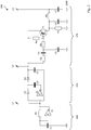
- FIG. 2 shows a circuit 200 for controlling a hood 100 as that of FIG. 1 ,
- the circuit 200 may in particular be provided by the capacitive proximity switch 145 in FIG FIG. 1 be included and used there as a boost 170.
- the circuit 200 includes an oscillator 205, a charge pump 210, and an evaluation circuit 215.
- the oscillator 205 may be formed in any manner. In the illustrated preferred embodiment, it is constructed as a tilt oscillator around an inverting gate A1 with a resistor R1 and a capacitor C1.
- the gate A1 preferably comprises a Schmitt trigger and can be produced, for example, in CMOS technology.
- the gate A1 is operated on the supply voltage 135.
- the oscillator 205 provides a square wave voltage that does not exceed the supply voltage 135.
- the charge pump 210 is configured to multiply the DC voltage at the terminal L1.
- the charge pump 210 is formed by an inverting gate A2, diodes D1 and D2, and capacitors C2 and C3.
- An output voltage of the charge pump 210 is applied to the exemplary marked terminal L2 and is preferably more than 150% of the input voltage at the terminal L1.
- the output voltage at terminal L2 is twice the input voltage at terminal L1 minus the sum of the freewheeling voltages of diodes D1 and D2.
- the illustrated charge pump 210 comprises two stages, but it may also be designed in one stage or with more than two stages. As a result, the input voltage, which can correspond at most to the supply voltage 135, can also be increased by a larger factor. An example of this will be given below with reference to FIG. 3 described in more detail.
- the evaluation circuit 215 comprises a capacitor C5, which in the illustration of FIG. 1 is formed by the electrode 150 and the ground potential 155.
- the capacitor C5 is charged by means of the resistor R2 and the capacitor C4 on the basis of the voltage at the terminal L2.
- the voltage between C4 and C5 changes as the capacitance of the capacitor C5 changes, particularly as a user 140 approaches or leaves the electrode 150. In this case, the voltage on the capacitor C5 temporarily rises or falls.
- the illustrated evaluation circuit 215 with a transistor T1, resistors R3 to R6 and capacitors C6 and C7. If the capacitance of the capacitor C5 increases by approaching the user 140 to the electrode 150, the voltage at the base of the transistor T1 decreases, so that the transistor T1 conducts and sets the resistor R6 to the voltage at the terminal L2. At the illustrated terminal L3, this is shown by a rapid increase in the voltage applied to C6, C7 and L3. The capacitor C5 is recharged via the resistor R2 and the capacitor C4, so that its voltage rises again until the transistor T1 blocks. Then, the voltage at the terminal L3 substantially resumes the ground potential 155 due to the resistance R5. In other words, a positive pulse can be observed at L3 when the user 140 comes into the area of the electrode 150.
- the voltage change across the capacitor C5 can also be determined in another embodiment by means of a microcontroller which digitizes the voltage at the capacitor C5 at regular intervals and determines changes numerically.
- the microcontroller can be used, for example, by the control device 125 in FIG. 1 includes his. As a result, a plurality of discrete components of the evaluation circuit 215 can be saved.
- the microcontroller may also be used to form the oscillator 205.
- the microcontroller may be programmed to provide a square wave voltage that is routed to the input of the charge pump 210 at terminal L1.
- the illustrated tilt oscillator about the inverting gate A1 can be omitted.
- the oscillator 205 may also be implemented in another way, for example by means of a quartz, a ceramic resonator or a feedback flip-flop.
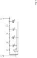
- FIG. 3 shows a variant of the charge pump 210 of FIG. 2 ,
- the variant shown here comprises a third stage with a diode D3 and a capacitor C2 'and an optional fourth stage with a diode D4 and a capacitor C3'.
- the four-stage charge pump 210 can realize a quadrupling of the input voltage at the terminal L1, reduced by the sum of the freewheeling voltages of the diodes D1 to D4.
- the three-stage charge pump 210 without the diode D4 and the capacitor C3 ' approximately a tripling - reduced by the sum of the freewheeling voltages of the diodes D1 to D3 - realize the input voltage to the terminal L1.
- FIG. 4 shows a flow diagram of an embodiment of the inventive method 400 for controlling a hood 100 as that of FIG. 1 ,
- the method 400 may be performed at least in part on the processing device 125.
- step 405 the supply voltage 135 is boosted, as described in detail above with respect to the charge pump 210.
- a capacitor C5 is then charged in a step 410, which is preferably formed by an electrode 150 with respect to a ground potential 155, as described above with reference to FIG FIG. 1 is explained in more detail. Steps 405 and 410 may be concurrent with other steps of method 400.
- a voltage across the capacitor C5 and the capacitance at the electrode 150, respectively, is determined. Subsequently, the determined voltage is compared with a predetermined value in a step 420. In a step 425, it is then decided whether the voltage has changed by more than a predetermined threshold or whether the rate of change exceeds another predetermined threshold. If this is not the case, this part of the method 400 can return to step 415. Otherwise, a function of the extractor hood 100 assigned to the electrode 150 is controlled in a step 430, preferably by means of the processing device 125. In particular, this function may include setting a predetermined speed of the fan 105 or a predetermined luminance of the lighting device 110. Subsequently, this part of the method 400 preferably returns to step 415.
- the invention can also be expressed in the following way.
- the purpose of the invention is to optimize a circuit 200 for capacitive measurement, so that switching signals through media 165, such as glass or plastic discs, which are thicker than, for example, 4 mm, are better detectable.
- the capacitive measurement is used on an extractor hood 100 for detecting a switching event in a control panel.
- the switching event may include approaching or removing a user 140 from a region of a sensor electrode 150.
- hoods 100 with glass or plastic front are usually capacitive touch control 145 used. Behind each switch is an electrode 150 for capacitance measurement.
- the relative permittivity ⁇ r of the capacitor C5, which comprises the electrode 150 is changed. That is, there is a change in the capacitance C of the capacitor C5.
- Previously known circuits 200 only work up to a limited material thickness d between capacitor electrode 150 and finger 140. Furthermore, usually only a low voltage 135 is available for detecting the capacitance. By a proposed circuit for boosting voltage 170, the voltage at the capacitor C5 is increased for detection and thus allows the use of thick media 165, through which a switching signal can be detected.
- the invention preferably includes for a voltage boost 170 to combine an oscillator 205 with a charge pump 210.
- a voltage boost 170 to combine an oscillator 205 with a charge pump 210.
- an oscillator 205 is implemented as a tilt oscillator with an inverting Schmitt trigger.
- the charge pump 210 includes two stages. It can also be equipped with one or more than two steps.
- the capacitance measurement can be constructed with a PNP transistor T1.
- the increase in capacitance C5 changes the current at the base and the signal at terminal L3 changes.
- the present invention has a number of advantages.
- the signal change at C5 as the user 140 approaches or removes the finger is substantially larger and thus easier to detect.
- switching signals can also be detected by thicker media, such as glass or plastic discs 165 of more than 4 mm.
- Advantages of the circuit 200 especially in those areas where only a small supply voltage 135 is available.
- the circuit 200 can be constructed inexpensively and compactly with their few components.
- the circuit 200 may be used in any capacitive touch panel 145.
Landscapes
- Engineering & Computer Science (AREA)
- Chemical & Material Sciences (AREA)
- Combustion & Propulsion (AREA)
- Mechanical Engineering (AREA)
- General Engineering & Computer Science (AREA)
- Switches That Are Operated By Magnetic Or Electric Fields (AREA)
Abstract
Description
- Die Erfindung betrifft eine Dunstabzugshaube. Insbesondere betrifft die Erfindung einen Näherungsschalter zur Steuerung einer Funktion der Dunstabzugshaube sowie ein Verfahren zur Steuerung einer Dunstabzugshaube.
- Dunstabzugshauben werden im Bereich einer Kochstelle angeordnet, um Dünste und Wrasen aus dem Bereich der Kochstelle abzusaugen. Üblicherweise wird die Dunstabzugshaube über der Kochstelle angebracht und umfasst ein elektrische angetriebenes Gebläse zum Absaugen von Luft sowie optional eine elektrische Beleuchtung der Kochstelle.
- Zur Steuerung von Funktionen der Dunstabzugshaube, insbesondere zum Betreiben des Gebläses in unterschiedlichen Leistungsstufen und/oder zur Steuerung der Beleuchtung ist eine Steuereinrichtung vorgesehen, die beispielsweise mittels eines kapazitiven Näherungsschalters, der auch Sensorschalter genannt wird, bedient werden kann. Der Näherungsschalter umfasst eine Sensorelektrode, deren Kapazität bezüglich dem Erde-Potential bestimmt werden kann. Nähert ein Benutzer beispielsweise einen Finger an die Elektrode an, so verändert sich die Kapazität und eine zugeordnete Funktion kann ausgelöst werden.
- Die Dunstabzugshaube umfasst eine Abdeckung, auf deren Innenseite die beschriebene Sensorelektrode angeordnet ist. Die Abdeckung ist üblicherweise aus Glas oder Kunststoff herstellbar und kann eine Dicke von mehreren Millimetern annehmen. Um den kapazitiven Näherungsschalter zu betätigen, kann der Benutzer einen Finger auf der Außenseite der Abdeckung in den Bereich der Elektrode halten.
- Je dicker die Abdeckung ist, desto schwächer ist die Beeinflussung der Kapazität durch den Finger des Benutzers. Der Erfindung liegt die Aufgabe zugrunde, eine Technik anzugeben, die den zuverlässigen Einsatz eines kapazitiven Näherungsschalters an einer Dunstabzugshaube auch bei einer dickeren Abdeckung zulässt. Die Erfindung löst diese Aufgabe mittels der Gegenstände der unabhängigen Ansprüche. Unteransprüche geben bevorzugte Ausführungsformen an.
- Der Erfindung liegt die Erkenntnis zugrunde, dass die Kapazität, die sich an der Elektrode einstellt, verbessert bestimmt werden kann, wenn die Elektrode auf eine erhöhte Spannung aufgeladen wird.
- Gemäß einem ersten Aspekt wird die Aufgabe gelöst durch eine Dunstabzugshaube mit einem kapazitiven Näherungsschalter zur Steuerung einer elektrischen Funktion der Dunstabzugshaube. Der Näherungsschalter ist dazu eingerichtet, eine Änderung einer elektrischen Kapazität an einer Elektrode zu bestimmen und die Elektrode ist mittels einer nichtleitenden Abdeckung gegenüber einem Benutzer abgedeckt. Die Dunstabzugshaube ist dadurch gekennzeichnet, dass eine Spannungsanhebung vorgesehen ist, um die Elektrode auf eine höhere Spannung als eine Versorgungsspannung des kapazitiven Näherungsschalters aufzuladen.
- Eine Steuereinrichtung für die Dunstabzugshaube arbeitet üblicherweise mit einer Versorgungsspannung, die allgemein mittels eines Netzteils aus einer Netzspannung (230 V in Europa) bereitgestellt wird. Die Versorgungsspannung liegt im Bereich von wenigen Volt, beispielsweise zwischen ca. 5 bis ca. 20 V. Wird die Elektrode auf eine höhere Spannung als die Versorgungsspannung aufgeladen, beispielsweise ca. 30 bis 60 V, so kann eine Kapazitätsänderung, die insbesondere durch das Bewegen eines Fingers eines Benutzers in den Bereich der Elektrode hervorgerufen sein kann, zu einer größeren Kapazitätsänderung führen, die auch leichter oder sicherer bestimmt werden kann. Vorteilhafterweise können dadurch eine Schaltsicherheit oder eine Bedienbarkeit der Dunstabzugshaube verbessert sein. Insbesondere können die Handlungs- oder Arbeitsbedingungen des Benutzers durch die verbesserte Bedienbarkeit der Dunstabzugshaube verbessert sein.
- Es ist besonders bevorzugt, dass die Spannungsanhebung eine Ladungspumpe umfasst. Die Versorgungsspannung umfasst üblicherweise eine Gleichspannung, die in einer anderen Ausführungsform auch mittels eines Gleichspannungswandlers, insbesondere eines Hochsetzstellers, auf eine höhere Spannung angehoben werden kann. Die Ladungspumpe hat jedoch den Vorteil, statt einer Spule nur einen Kondensator zu erfordern, wodurch die Ladungspumpe vergleichsweise kostengünstig aufgebaut werden kann. Die Aufladung der Elektrode erfordert üblicherweise nur einen geringen Strom, sodass schwach dimensionierte und somit kostengünstige Bauelemente, insbesondere Kondensatoren, verwendet werden können.
- Vorzugsweise umfasst die Ladungspumpe mehrere kaskadierte, also hintereinandergeschaltete Stufen. Eine Stufe der Ladungspumpe kann ihre Eingangsspannung ungefähr verdoppeln. Durch das Kaskadieren mehrerer Stufen kann beispielsweise auch eine Verdreifachung, Vervierfachung oder weitere Vervielfachung bewirkt werden. Die einzelnen Stufen können in einander entsprechender Weise aufgebaut sein, wodurch die Spannungsanhebung leicht realisiert werden kann. In einer Ausführungsform wird die Versorgungsspannung mit einem Faktor multipliziert, die der Anzahl der Stufen entspricht. Allerdings kann die Ausgangsspannung um die Summe der Leerlaufspannungen von Dioden verringert sein, die in jeder Stufe vorgesehen sind.
- Allgemein ist bevorzugt, dass die Versorgungsspannung um wenigstens 150 % angehoben wird. Weiter ist bevorzugt, dass die Anhebung 200 % oder mehr beträgt. In einer besonders bevorzugten Ausführungsform der Spannungsanhebung, die unten mit Bezug auf
Figur 2 noch genauer beschrieben wird, wird eine Verdopplung der Versorgungsspannung - abzüglich der Leerlaufspannungen zweier Dioden - bewirkt. - In einer weiteren Ausführungsform umfasst die Dunstabzugshaube einen Oszillator. Der Oszillator ist vorzugsweise als Kippschwinger ausgeführt und dient zur Bereitstellung einer Wechselspannung für die Spannungsanhebung. Der Oszillator wird vorzugsweise auf der Basis der Versorgungsspannung betrieben. Der Kippschwinger kann einfach und kostengünstig aufgebaut sein. Die bereitgestellte Wechselspannung muss nicht besonders frequenzstabil sein, sodass der Kippschwinger ohne Bedenken werden kann.
- In einer Ausführungsform umfasst der Kippschwinger ein erstes invertierendes Gatter und die Ladungspumpe umfasst ein zweites invertierendes Gatter. Dabei sind beide Gatter vorteilhafterweise in einem gemeinsamen elektronischen Bauteil integriert. Das elektronische Bauteil kann insbesondere eine Standard-CMOS-Schaltung umfassen. Beispielsweise sind in der integrierten Schaltung CD4093 vier invertierende Gatter mit Schmitt-Trigger enthalten, sodass beispielsweise ein Oszillator und drei Stufen einer Ladungspumpe kostengünstig aufgebaut werden können.
- In einer weiteren Ausführungsform ist ein Mikrocontroller vorgesehen, der dazu eingerichtet ist, die elektrische Funktion der Dunstabzugshaube zu steuern. In einer Variante realisiert der Mikrocontroller einen Oszillator zur Bereitstellung einer Wechselspannung für die Spannungsanhebung. Beispielsweise kann der Mikrocontroller einen programmierbaren Zähler umfassen, der eine vorbestimmte Taktfrequenz passend herunterteilt und nach außen zugänglich macht. In einer anderen Ausführungsform kann die Wechselspannung auch mittels eines Programms generiert werden, das auf dem Mikrocontroller abläuft und die Invertierung eines Ausgangssignals in vorbestimmten Zeitabständen realisiert.
- Der Mikrocontroller kann zusätzlich oder alternativ auch dazu eingerichtet sein, eine Spannung an der Elektrode zu bestimmen und mit einer zuvor bestimmten Spannung zu vergleichen. Anders ausgedrückt kann der Mikrocontroller die Spannung an der Elektrode überwachen und eine Veränderung der Kapazität auf der Basis einer Veränderung der Spannung bestimmen. Überschreitet die Änderung der Kapazität einen bestimmten Wert oder überschreitet die Änderungsgeschwindigkeit der Kapazität einen bestimmten Wert, so kann das Aktivieren oder Deaktivieren des Näherungsschalters durch einen Benutzer bestimmt werden. In der Folge kann eine dem kapazitiven Näherungsschalter zugeordnete Funktion der Dunstabzugshaube aktiviert oder deaktiviert werden.
- Gemäß einem weiteren Aspekt wird die Aufgabe gelöst durch ein Verfahren zur Steuerung einer Dunstabzugshaube, das die Schritte des Anhebens einer Versorgungsspannung auf eine höhere Spannung, des Aufladens einer Kapazität an einer Elektrode mittels der angehobenen Spannung, des Bestimmens einer durch einen Benutzer der Dunstabzugshaube bewirkten Veränderung der Kapazität, und das Steuern einer elektrischen Funktion der Dunstabzugshaube in Abhängigkeit der bestimmten Veränderung umfasst.
- Das Anheben der Versorgungsspannung auf eine höhere Spannung kann vorzugsweise durch Verwendung einer Ladepumpe erfolgen. Als Aufladen der Kapazität an einer Elektrode wird vorzugsweise das Einstellen einer Kapazität an der als Kondensator wirkenden Kombination aus Sensorelektrode und Erdungselektrode (Ground) verstanden.
- Vorteile und Merkmale, die bezüglich der Dunstabzugshaube beschrieben wurden, gelten soweit anwendbar entsprechend für das erfindungsgemäße Verfahren und umgekehrt.
- Zumindest Teile des Verfahrens können mittels eines Mikrocomputers oder Mikrocontrollers durchgeführt werden.
- Die Erfindung wird nun mit Bezug auf die beigefügten Figuren genauer beschrieben, wobei
- Fig. 1
- eine schematische Darstellung von Teilen einer Dunstabzugshaube;
- Fig. 2
- eine Schaltung zur Steuerung einer Dunstabzugshaube;
- Fig. 3
- eine Variante der Schaltung von
Fig. 2 ; und - Fig. 4
- ein Ablaufdiagramm eines Verfahrens zum Steuern einer Dunstabzugshaube
-
Figur 1 zeigt eine schematische Darstellung von Teilen einer Dunstabzugshaube 100. Die Dunstabzugshaube 100 ist dazu eingerichtet, im Bereich einer Kochstelle angebracht zu werden, um Luft oder Wrasen abzutransportieren. Die Dunstabzugshaube 100 umfasst einen Ventilator 105, der auch als Gebläse bezeichnet wird, und optional eine Beleuchtungseinrichtung 110. Ein Anschluss 115 ist zur Verbindung mit einem Stromnetz vorgesehen. Die Beleuchtungseinrichtung 110 und der Ventilator 105 werden vorzugsweise mit elektrischem Strom betrieben, der vom Anschluss 115 bezogen wird, wobei eine Schalteinrichtung 120 zur Steuerung des Ventilators 105 und der Beleuchtungseinrichtung 110 vorgesehen sein kann. - Die Dunstabzugshaube 100 wird vorzugsweise mittels einer Steuereinrichtung 125 gesteuert. Die Steuereinrichtung 125 kann einen programmierbaren Mikrocomputer oder Mikrocontroller umfassen und wird mit einer elektrischen Spannung betrieben, die vorzugsweise mittels eines Netzteils 130, das mit dem Anschluss 115 verbunden ist, bereitgestellt wird. Eine durch das Netzteil 130 bereitgestellte Versorgungsspannung 135 liegt üblicherweise im Bereich zwischen ca. 5 und ca. 20 V.
- Um einen Steuerungswunsch eines Benutzers 140 abzutasten, ist ein kapazitiver Näherungsschalter 145 vorgesehen, der mit der Steuereinrichtung 125 verbunden ist. Der Näherungsschalter 145 umfasst eine Elektrode 150, die auch als Kondensatorelektrode oder Sensorelektrode bezeichnet werden kann und deren Kapazität bezüglich eines ErdePotentials 155 mittels einer Sensorschaltung 160 bestimmt werden kann. Dazu lädt die Sensorschaltung 160 die Elektrode 150 bezüglich des Erde-Potentials 155 auf der Basis der Versorgungsspannung 135 auf und überwacht die Spannung, die sich an der Elektrode 150 einstellt. Nähert sich der Benutzer 140 mit einem Körperteil an die Elektrode 150 an, so beeinflusst er dadurch deren Kapazität bezüglich des Erde-Potentials 155, sodass sich auch die an der Elektrode 150 anliegende Spannung ändert. Diese Spannungsänderung wird durch die Sensorschaltung 160 abgetastet und ein korrespondierendes Signal wird an die Steuereinrichtung 125 weitergegeben, die daraufhin eine elektrische Funktion der Dunstabzugshaube 100, insbesondere einen Betriebszustand des Ventilators 105 oder der Beleuchtungseinrichtung 110, steuern kann.
- Die Elektrode 150 ist üblicherweise elektrisch isoliert von einer Außenseite der Dunstabzugshaube 100. Vorzugsweise umfasst die Dunstabzugshaube 100 eine Abdeckung 165, auf deren Innenseite die Elektrode 150 angebracht ist. Die Abdeckung 165 kann aus einem Glas oder Kunststoff hergestellt sein und bildet vorzugsweise einen Teil eines Gehäuses der Dunstabzugshaube 100, insbesondere der Sichthaube der Dunstabzugshaube 100. Die Abdeckung 165 kann auch als Blende einer Bedieneinheit der Dunstabzugshaube 100 bezeichnet werden.
- Die Kapazität an der Elektrode 150 ist abhängig von der Größe A einer Oberfläche der Elektrode 150 und einem Abstand zwischen dem Benutzer 140 und der Elektrode 150. Die Abdeckung 165 weist eine Wandstärke d auf, sodass der Abstand des Benutzers 140 zur Elektrode 150 nicht kleiner als d werden kann. Je größer die Wandstärke d ist, desto geringer ist daher der Unterschied zwischen der Kapazität an der Elektrode 150 in Anwesenheit und in Abwesenheit des Benutzers 140. Es wird vorgeschlagen, die Elektrode 150 auf eine höhere Spannung als die Versorgungsspannung 135 aufzuladen, um eine Spannungsänderung, die durch die Kapazitätsänderung bewirkt sein kann, verbessert detektieren zu können. Insbesondere wird erfindungsgemäß vorgeschlagen, eine Spannungsanhebung 170 vorzusehen, um die Versorgungsspannung 135 auf eine höhere Spannung anzuheben und die Elektrode 150 mittels der angehobenen Spannung aufzuladen.
-
Figur 2 zeigt eine Schaltung 200 zur Steuerung einer Dunstabzugshaube 100 wie der vonFigur 1 . Die Schaltung 200 kann insbesondere vom kapazitiven Näherungsschalter 145 inFigur 1 umfasst sein und dort als Spannungsanhebung 170 eingesetzt werden. - Vorzugsweise umfasst die Schaltung 200 einen Oszillator 205, eine Ladungspumpe 210 und eine Auswerteschaltung 215. Der Oszillator 205 kann auf beliebige Weise gebildet werden. In der dargestellten, bevorzugten Ausführungsform ist er als Kippschwinger um ein invertierendes Gatter A1 mit einem Widerstand R1 und einem Kondensator C1 aufgebaut. Das Gatter A1 umfasst vorzugsweise einen Schmitt-Trigger und kann beispielsweise in CMOS-Technik hergestellt sein. Das Gatter A1 wird an der Versorgungsspannung 135 betrieben. An der beispielhaft dargestellten Klemme L1 stellt der Oszillator 205 eine Rechteckspannung bereit, die die Versorgungsspannung 135 nicht übersteigt.
- Die Ladungspumpe 210 ist dazu eingerichtet, die Gleichspannung an der Klemme L1 zu vervielfachen. Dazu sind unterschiedliche Grundschaltungen bekannt, von denen eine bevorzugte in
Figur 2 dargestellt ist. Die Ladungspumpe 210 ist durch ein invertierendes Gatter A2, Dioden D1 und D2 sowie Kondensatoren C2 und C3 gebildet. Eine Ausgangsspannung der Ladungspumpe 210 liegt an der exemplarisch eingezeichneten Klemme L2 an und beträgt vorzugsweise mehr als 150 % der Eingangsspannung an der Klemme L1. In der dargestellten Ausführungsform beträgt die Ausgangsspannung an der Klemme L2 das Doppelte der Eingangsspannung an der Klemme L1 abzüglich der Summe der Freilaufspannungen der Dioden D1 und D2. Die dargestellte Ladungspumpe 210 umfasst zwei Stufen, sie kann jedoch auch einstufig oder mit mehr als zwei Stufen ausgeführt sein. Dadurch kann die Eingangsspannung, die maximal der Versorgungsspannung 135 entsprechen kann, auch um einen größeren Faktor angehoben werden. Ein Beispiel hierzu wird unten mit Bezug aufFigur 3 genauer beschrieben. - Die Auswerteschaltung 215 umfasst einen Kondensator C5, der in der Darstellung von
Figur 1 durch die Elektrode 150 und das Erde-Potential 155 gebildet ist. Der Kondensator C5 wird mittels des Widerstands R2 und des Kondensators C4 auf der Basis der Spannung an der Klemme L2 aufgeladen. Die Spannung zwischen C4 und C5 verändert sich dann, wenn sich die Kapazität des Kondensators C5 ändert, insbesondere wenn sich ein Benutzer 140 der Elektrode 150 annähert oder von ihr entfernt. In diesem Fall steigt oder fällt die Spannung am Kondensator C5 vorübergehend an oder fällt ab. - Eine Möglichkeit, eine derartige Änderung auszuwerten, wird mit der dargestellten Auswerteschaltung 215 mit einem Transistor T1, Widerständen R3 bis R6 und Kondensatoren C6 und C7 realisiert. Vergrößert sich die Kapazität des Kondensators C5 durch Annähern des Benutzers 140 an die Elektrode 150, so sinkt die Spannung an der Basis des Transistors T1 ab, sodass der Transistor T1 leitet und den Widerstand R6 an die Spannung an der Klemme L2 legt. An der beispielhaft dargestellten Klemme L3 zeigt sich dies durch einen raschen Anstieg der an C6, C7 und L3 anliegenden Spannungen. Der Kondensator C5 wird über den Widerstand R2 und den Kondensator C4 nachgeladen, sodass seine Spannung wieder ansteigt bis der Transistor T1 sperrt. Dann entspricht die Spannung an der Klemme L3 wegen des Widerstands R5 im Wesentlichen wieder dem Massepotential 155. Anders ausgedrückt kann an L3 ein positiver Impuls beobachtet werden, wenn der Benutzer 140 in den Bereich der Elektrode 150 gelangt.
- Die Spannungsänderung am Kondensator C5 kann in einer anderen Ausführungsform auch mittels eines Mikrocontrollers bestimmt werden, der in regelmäßigen Abständen die Spannung am Kondensator C5 digitalisiert und Änderungen numerisch bestimmt. Der Mikrocontroller kann beispielsweise von der Steuereinrichtung 125 in
Figur 1 umfasst sein. Dadurch können mehrere diskrete Bauelemente der Auswerteschaltung 215 eingespart werden. - Der Mikrocontroller kann auch dazu verwendet werden, den Oszillator 205 zu bilden. Dazu kann der Mikrocontroller dazu programmiert werden, eine Rechteckspannung bereitzustellen, die an den Eingang der Ladungspumpe 210 an der Klemme L1 geleitet wird. Der dargestellte Kippschwinger um das invertierende Gatter A1 kann dabei entfallen. In noch einer weiteren Ausführungsform kann der Oszillator 205 auch auf eine andere Weise realisiert sein, beispielsweise mittels eines Quarzes, eines keramischen Resonators oder eines rückgekoppelten Flipflops.
-
Figur 3 zeigt eine Variante der Ladungspumpe 210 vonFigur 2 . Die hier dargestellte Variante umfasst eine dritte Stufe mit einer Diode D3 und einem Kondensator C2' und eine optionale vierte Stufe mit einer Diode D4 und einem Kondensator C3'. Die vierstufige Ladungspumpe 210 kann eine Vervierfachung der Eingangsspannung an der Klemme L1, vermindert um die Summe der Freilaufspannungen der Dioden D1 bis D4, realisieren. In entsprechender Weise kann die dreistufige Ladungspumpe 210 ohne die Diode D4 und den Kondensator C3' annähernd eine Verdreifachung - vermindert um die Summe der Freilaufspannungen der Dioden D1 bis D3 - der Eingangsspannung an der Klemme L1 realisieren. -
Figur 4 zeigt ein Ablaufdiagramm einer Ausführungsform des erfindungsgemäßen Verfahrens 400 zum Steuern einer Dunstabzugshaube 100 wie der vonFigur 1 . Das Verfahren 400 kann wenigstens in Teilen auf der Verarbeitungseinrichtung 125 ausgeführt werden. - In einem Schritt 405 wird die Versorgungsspannung 135 angehoben, wie oben bezüglich der Ladungspumpe 210 ausführlich beschrieben ist. Mittels der angehobenen Spannung wird dann in einem Schritt 410 ein Kondensator C5 aufgeladen, der vorzugsweise durch eine Elektrode 150 bezüglich eines Erde-Potentials 155 gebildet ist, wie oben mit Bezug auf
Figur 1 näher erläutert ist. Die Schritte 405 und 410 können nebenläufig zu weiteren Schritten des Verfahrens 400 ablaufen. - In einem Schritt 415 wird eine Spannung an dem Kondensator C5 bzw. der Kapazität an der Elektrode 150 bestimmt. Anschließend wird die bestimmte Spannung in einem Schritt 420 mit einem zuvor bestimmten Wert verglichen. In einem Schritt 425 wird dann entschieden, ob sich die Spannung um mehr als einen vorbestimmten Schwellenwert geändert hat oder ob die Änderungsgeschwindigkeit einen anderen vorbestimmten Schwellenwert übersteigt. Ist dies nicht der Fall, so kann dieser Teil des Verfahrens 400 zum Schritt 415 zurückkehren. Andernfalls wird in einem Schritt 430, vorzugsweise mittels der Verarbeitungseinrichtung 125, eine der Elektrode 150 zugeordnete Funktion der Dunstabzugshaube 100 gesteuert. Diese Funktion kann insbesondere das Einstellen einer vorbestimmten Drehzahl des Ventilators 105 oder einer vorbestimmten Leuchtstärke der Beleuchtungseinrichtung 110 umfassen. Anschließend kehrt dieser Teil des Verfahrens 400 vorzugsweise zum Schritt 415 zurück.
- Die Erfindung kann auch auf die folgende Weise ausgedrückt werden.
- Zweck der Erfindung ist, eine Schaltung 200 zur kapazitiven Messung zu optimieren, so dass Schaltsignale durch Medien 165, wie beispielsweise Glas- oder Kunststoffscheiben, die dicker als beispielsweise 4 mm sind, besser detektierbar sind. Die kapazitive Messung wird an einer Dunstabzugshaube 100 zur Detektion eines Schaltereignisses in einem Bedienteil eingesetzt. Das Schaltereignis kann ein Annähern oder ein Entfernen eines Benutzers 140 aus einem Bereich einer Sensorelektrode 150 umfassen.
- In Dunstabzugshauben 100 mit Glas- oder Kunststofffront (Blende, Halter, Abdeckung 165) werden meist kapazitive Touchbedienteile 145 eingesetzt. Hinter jedem Schalter befindet sich eine Elektrode 150 für eine Kapazitätsmessung. Durch die Annäherung beispielsweise eines Fingers des Benutzers an die Touchfläche im Bereich der Elektrode 150 wird die relative Permittivität εr des Kondensators C5 verändert, der die Elektrode 150 umfasst. Das heißt, es erfolgt eine Änderung der Kapazität C des Kondensators C5.
- Die Kapazität C des Kondensators C5, der durch die Elektrode 150 und das ErdePotential 155 gebildet ist, bestimmt sich wie folgt:

- Beispiele für εr:
- εr Luft: ca. 1
- εr Wasser (menschlicher Finger): ca. 80.
- Wird also ein Objekt wie ein Finger des Benutzers 140 in den Bereich des Kondensators C5 gebracht, so verändert sich dessen Kapazität C.
- Bisher bekannte Schaltungen 200 arbeiten nur bis zu einer begrenzten Materialdicke d zwischen Kondensatorelektrode 150 und Finger 140. Des Weiteren steht meist nur eine geringe Spannung 135 zur Detektion der Kapazität zur Verfügung. Durch eine vorgeschlagene Schaltung zur Spannungsanhebung 170 wird die Spannung am Kondensator C5 zur Detektion erhöht und ermöglicht somit den Einsatz von dicken Medien 165, durch die ein Schaltsignal detektiert werden kann.
- Die Erfindung beinhaltet vorzugsweise für eine Spannungsanhebung 170 einen Oszillator 205 mit einer Ladungspumpe 210 zu kombinieren. Hierdurch entsteht wegen des Einsatzes von nur wenigen Bauteilen eine kostengünstige Spannungsanhebung 170. Durch die Spannungsanhebung 170 kann auch durch dicke Materialien 165 eine Kapazitätsänderung detektiert werden. Durch die Anzahl an Kaskaden (Stufen) kann die Spannungshöhe beliebig angepasst werden.
- In einem Beispiel wird ein Oszillator 205 als Kippschwinger mit invertierendem Schmitt-Trigger ausgeführt. Die Ladungspumpe 210 enthält zwei Stufen. Sie kann wahlweise auch mit einer oder mehr als zwei Stufen ausgestattet werden.
- Die Kapazitätsmessung kann mit einem PNP Transistor T1 aufgebaut sein. Durch die Kapazitätserhöhung C5 wird der Strom an der Basis verändert und das Signal an der Klemme L3 ändert sich.
- Die vorliegende Erfindung weist eine Reihe von Vorteilen auf. Durch die Schaltung 200 ist die Signaländerung an C5 bei Annäherung oder Entfernung des Fingers des Benutzers 140 wesentlich größer und somit leichter zu detektieren. Durch die Schaltung 200 können Schaltsignale auch durch dickere Medien, wie beispielsweise Glas oder Kunststoffscheiben 165 von mehr als 4 mm detektiert werden. Vorteile bietet die Schaltung 200 besonders in solchen Bereichen, in denen nur eine geringe Versorgungsspannung 135 zur Verfügung steht. Die Schaltung 200 kann mit ihren wenigen Komponenten kostengünstig und platzsparend aufgebaut werden. Die Schaltung 200 kann in jedem kapazitiven Touchbedienteil 145 eingesetzt werden.
-
- 100
- Dunstabzugshaube
- 105
- Ventilator
- 110
- Beleuchtungseinrichtung
- 115
- Anschluss
- 120
- Schalteinrichtung
- 125
- Steuereinrichtung
- 130
- Netzteil
- 135
- Versorgungsspannung
- 140
- Benutzer
- 145
- kapazitiver Näherungsschalter
- 150
- Elektrode
- 155
- Erde-Potential (GND)
- 160
- Sensorschaltung
- 165
- Abdeckung
- 170
- Spannungsanhebung
- d
- Wandstärke
- A
- Oberfläche
- 200
- Schaltung
- 205
- Oszillator
- 210
- Ladungspumpe
- 215
- Auswerteschaltung
- L1-L3
- Klemmen
- A1, A2
- invertierende Gatter
- R1-6
- Widerstände
- C1-7
- Kondensatoren
- T1
- Transistor
- D1-D4
- Dioden
- 400
- Verfahren
- 405
- Anheben Versorgungsspannung
- 410
- Aufladen Kapazität
- 415
- Bestimmen Spannung an Kapazität
- 420
- Vergleichen mit früher bestimmtem Wert
- 425
- Unterschied oder Änderungsgeschwindigkeit > Schwellenwert?
- 430
- Steuern Funktion
Claims (9)
- Dunstabzugshaube (100) mit einem kapazitiven Näherungsschalter (145) zur Steuerung einer elektrischen Funktion der Dunstabzugshaube (100),- der dazu eingerichtet ist, eine Änderung einer elektrischen Kapazität an einer Elektrode (150) zu bestimmen,- die mittels einer nichtleitenden Abdeckung (165) gegenüber einem Benutzer (140) abgedeckt ist;dadurch gekennzeichnet, dass- eine Spannungsanhebung (210) vorgesehen ist, um die Elektrode (150) auf eine höhere Spannung als eine Versorgungsspannung (135) des kapazitiven Näherungsschalters (145) aufzuladen.
- Dunstabzugshaube (100) nach Anspruch 1, wobei die Spannungsanhebung (170) eine Ladungspumpe (210) umfasst.
- Dunstabzugshaube (100) nach Anspruch 2, wobei die Ladungspumpe (210) mehrere kaskadierte Stufen (D1, C2; D2, C3; D3, C2'; D4, C3') aufweist.
- Dunstabzugshaube (100) nach einem der vorangehenden Ansprüche, wobei die Versorgungsspannung (135) um wenigstens 150 % angehoben wird.
- Dunstabzugshaube (100) nach einem der vorangehenden Ansprüche, ferner umfassend einen als Kippschwinger ausgeführten Oszillator (205) zur Bereitstellung einer Wechselspannung für die Spannungsanhebung (210).
- Dunstabzugshaube (100) nach Anspruch 5 soweit sich dieser auf Ansprüche 2 oder 3 bezieht, wobei der Kippschwinger (205) ein erstes invertierendes Gatter (A1) und die Ladungspumpe (210) ein zweites invertierendes Gatter (A2) umfasst und beide Gatter (A1, A2) in einem gemeinsamen elektronischen Bauteil integriert sind.
- Dunstabzugshaube (100) nach einem der Ansprüche 1 bis 4, ferner umfassend einen Mikrocontroller (125), der dazu eingerichtet ist, die elektrische Funktion der Dunstabzugshaube (100) zu steuern, wobei der Mikrocontroller (125) einen Oszillator (205) zur Bereitstellung einer Wechselspannung für die Spannungsanhebung (210) realisiert.
- Dunstabzugshaube (100) nach einem der vorangehenden Ansprüche, ferner umfassend einen Mikrocontroller (125), der dazu eingerichtet ist, die elektrische Funktion der Dunstabzugshaube (100) zu steuern, wobei der Mikrocontroller (125) ferner dazu eingerichtet ist, eine Spannung an der Elektrode (150) zu bestimmen und mit einer zuvor bestimmten Spannung zu vergleichen.
- Verfahren (400) zur Steuerung einer Dunstabzugshaube (100), wobei das Verfahren (400) folgende Schritte aufweist:- Anheben (405) einer Versorgungsspannung (135) auf eine höhere Spannung;- Aufladen (410) einer Kapazität einer Elektrode (150) mittels der angehobenen Spannung;- Bestimmen (420, 425) einer durch einen Benutzer (140) der Dunstabzugshaube bewirkten Veränderung der Kapazität; und- Steuern (430) einer elektrischen Funktion der Dunstabzugshaube (100) in Abhängigkeit der bestimmten Veränderung.
Applications Claiming Priority (1)
| Application Number | Priority Date | Filing Date | Title |
|---|---|---|---|
| DE102016202786.7A DE102016202786B4 (de) | 2016-02-23 | 2016-02-23 | Dunstabzugshaube mit Näherungsschalter und Verfahren zur Steuerung einer Dunstabzugshaube |
Publications (2)
| Publication Number | Publication Date |
|---|---|
| EP3211328A1 true EP3211328A1 (de) | 2017-08-30 |
| EP3211328B1 EP3211328B1 (de) | 2020-08-26 |
Family
ID=57906560
Family Applications (1)
| Application Number | Title | Priority Date | Filing Date |
|---|---|---|---|
| EP17153324.3A Active EP3211328B1 (de) | 2016-02-23 | 2017-01-26 | Dunstabzugshaube mit näherungsschalter und verfahren zur steuerung einer dunstabzugshaube |
Country Status (2)
| Country | Link |
|---|---|
| EP (1) | EP3211328B1 (de) |
| DE (1) | DE102016202786B4 (de) |
Citations (4)
| Publication number | Priority date | Publication date | Assignee | Title |
|---|---|---|---|---|
| EP2261568A1 (de) * | 2009-06-12 | 2010-12-15 | Electrolux Home Products Corporation N.V. | Bedieneinrichtung für Küchengerät |
| EP2275907A2 (de) * | 2009-07-16 | 2011-01-19 | Apple Inc. | Erdschlussdetektion für berührungsempfindliche Vorrichtung |
| US8040142B1 (en) * | 2006-03-31 | 2011-10-18 | Cypress Semiconductor Corporation | Touch detection techniques for capacitive touch sense systems |
| US20130241630A1 (en) * | 2012-03-16 | 2013-09-19 | Cypress Semiconductor Corporation | Touch Sensor Driver With Selectable Charge Source |
Family Cites Families (5)
| Publication number | Priority date | Publication date | Assignee | Title |
|---|---|---|---|---|
| FR2735920B1 (fr) * | 1995-06-21 | 1997-10-10 | Sgs Thomson Microelectronics | Generateur de haute tension avec oscillateur asservi a basse tension d'alimentation |
| US6191660B1 (en) * | 1999-03-24 | 2001-02-20 | Cypress Semiconductor Corp. | Programmable oscillator scheme |
| US6377129B1 (en) * | 1999-04-30 | 2002-04-23 | Conexant Systems, Inc. | Programmable relaxation oscillator |
| DE102009012004A1 (de) * | 2009-02-26 | 2010-10-07 | E.G.O. Elektro-Gerätebau GmbH | Dunstabzugshaube und Bedienverfahren dafür |
| DE102009028221A1 (de) * | 2009-08-04 | 2011-02-17 | BSH Bosch und Siemens Hausgeräte GmbH | Dunstabzugshaube mit Bedieneinheit |
-
2016
- 2016-02-23 DE DE102016202786.7A patent/DE102016202786B4/de active Active
-
2017
- 2017-01-26 EP EP17153324.3A patent/EP3211328B1/de active Active
Patent Citations (4)
| Publication number | Priority date | Publication date | Assignee | Title |
|---|---|---|---|---|
| US8040142B1 (en) * | 2006-03-31 | 2011-10-18 | Cypress Semiconductor Corporation | Touch detection techniques for capacitive touch sense systems |
| EP2261568A1 (de) * | 2009-06-12 | 2010-12-15 | Electrolux Home Products Corporation N.V. | Bedieneinrichtung für Küchengerät |
| EP2275907A2 (de) * | 2009-07-16 | 2011-01-19 | Apple Inc. | Erdschlussdetektion für berührungsempfindliche Vorrichtung |
| US20130241630A1 (en) * | 2012-03-16 | 2013-09-19 | Cypress Semiconductor Corporation | Touch Sensor Driver With Selectable Charge Source |
Also Published As
| Publication number | Publication date |
|---|---|
| EP3211328B1 (de) | 2020-08-26 |
| DE102016202786B4 (de) | 2017-11-02 |
| DE102016202786A1 (de) | 2017-08-24 |
Similar Documents
| Publication | Publication Date | Title |
|---|---|---|
| DE102008005783B4 (de) | Feuchteunabhängiger kapazitiver Einklemmschutz | |
| DE10005173A1 (de) | Schaltungsanordnung für ein Sensorelement | |
| DE102008057823A1 (de) | Kapazitives Sensorsystem | |
| EP3149855A1 (de) | Sensoreinrichtung für ein kraftfahrzeug | |
| DE102014117823A1 (de) | Lenkrad für ein Kraftfahrzeug mit einem Sensorsystem und Verfahren zum Erkennen einer Anwesenheit einer menschlichen Hand in einem Greifbereich eines solchen Lenkrads | |
| DE102013209644A1 (de) | Näherungsschalteranordnung mit nichtschaltkontakt und verfahren | |
| EP3719465B1 (de) | Elektrisches installationsmodul | |
| DE68911758T2 (de) | Die Eigenschaften eines Flüssigkristalles nutzender Berührungsschalter. | |
| DE102015104343A1 (de) | Näherungsschalter-anordnung und verfahren zur abstimmung derselben | |
| EP3211328B1 (de) | Dunstabzugshaube mit näherungsschalter und verfahren zur steuerung einer dunstabzugshaube | |
| DE102011078369A1 (de) | Kapazitive Sensoreinrichtung sowie Verfahren zum Kalibrieren einer kapazitiven Sensoreinrichtung | |
| WO2014000891A2 (de) | Kapazitiver sensor für eine kollisionsschutzvorrichtung | |
| DE102011056226A1 (de) | Sensorsystem sowie Verfahren zur Reduktion einer Einschwingzeit eines Sensorsystems | |
| DE102018113879A1 (de) | Verfahren zur Erkennung einer Berührung einer handbetätigten Lenkeinrichtung, insbesondere eines Fahrzeuglenkrads, und Vorrichtung zur Durchführung des Verfahrens | |
| WO2008077503A2 (de) | Vorrichtung und verfahren zur positionsbestimmung bezogen auf eine oberfläche | |
| DE102010039545B4 (de) | Verfahren zum Erfassen von Bewegungen eines Objekts sowie Sensorsystem und Handgerät hierfür | |
| EP2429078B1 (de) | Kapazitive Bedieneinrichtung für ein Haushaltsgerät, Haushaltsgerät und Verfahren zum Betreiben einer kapazitiven Bedieneinrichtung in einem Haushaltsgerät | |
| EP3182860B1 (de) | Möbel mit sensoreinrichtung | |
| DE102009021719A1 (de) | Sensorschaltung | |
| DE102006025069B4 (de) | Sensorelement-Anordnung für eine Bedieneinrichtung und Verfahren zum Betrieb einer solchen Sensorelement-Anordnung | |
| DE102015109549A1 (de) | Näherungsschalteranordnung mit einer Furche zwischen benachbarten Näherungssensoren | |
| DE102014104583A1 (de) | Mobile Bedieneinheit sowie Verfahren zum Bereitstellen einer Gestiksteuerung einer mobilen Bedieneinheit | |
| EP3168992A1 (de) | Bedienvorrichtung und verfahren zum betreiben einer bedienvorrichtung | |
| DE102006045737A1 (de) | Schaltungsanordnung zum Bestimmen einer Kapazität eines kapazitiven Sensorelements | |
| EP2507913B1 (de) | Haushaltsgerät mit einer bedieneinrichtung und verfahren zum bedienen eines haushaltsgeräts |
Legal Events
| Date | Code | Title | Description |
|---|---|---|---|
| PUAI | Public reference made under article 153(3) epc to a published international application that has entered the european phase |
Free format text: ORIGINAL CODE: 0009012 |
|
| STAA | Information on the status of an ep patent application or granted ep patent |
Free format text: STATUS: THE APPLICATION HAS BEEN PUBLISHED |
|
| AK | Designated contracting states |
Kind code of ref document: A1 Designated state(s): AL AT BE BG CH CY CZ DE DK EE ES FI FR GB GR HR HU IE IS IT LI LT LU LV MC MK MT NL NO PL PT RO RS SE SI SK SM TR |
|
| AX | Request for extension of the european patent |
Extension state: BA ME |
|
| STAA | Information on the status of an ep patent application or granted ep patent |
Free format text: STATUS: REQUEST FOR EXAMINATION WAS MADE |
|
| 17P | Request for examination filed |
Effective date: 20180228 |
|
| RBV | Designated contracting states (corrected) |
Designated state(s): AL AT BE BG CH CY CZ DE DK EE ES FI FR GB GR HR HU IE IS IT LI LT LU LV MC MK MT NL NO PL PT RO RS SE SI SK SM TR |
|
| STAA | Information on the status of an ep patent application or granted ep patent |
Free format text: STATUS: EXAMINATION IS IN PROGRESS |
|
| 17Q | First examination report despatched |
Effective date: 20190819 |
|
| GRAP | Despatch of communication of intention to grant a patent |
Free format text: ORIGINAL CODE: EPIDOSNIGR1 |
|
| STAA | Information on the status of an ep patent application or granted ep patent |
Free format text: STATUS: GRANT OF PATENT IS INTENDED |
|
| INTG | Intention to grant announced |
Effective date: 20200414 |
|
| GRAS | Grant fee paid |
Free format text: ORIGINAL CODE: EPIDOSNIGR3 |
|
| GRAA | (expected) grant |
Free format text: ORIGINAL CODE: 0009210 |
|
| STAA | Information on the status of an ep patent application or granted ep patent |
Free format text: STATUS: THE PATENT HAS BEEN GRANTED |
|
| AK | Designated contracting states |
Kind code of ref document: B1 Designated state(s): AL AT BE BG CH CY CZ DE DK EE ES FI FR GB GR HR HU IE IS IT LI LT LU LV MC MK MT NL NO PL PT RO RS SE SI SK SM TR |
|
| REG | Reference to a national code |
Ref country code: GB Ref legal event code: FG4D Free format text: NOT ENGLISH |
|
| REG | Reference to a national code |
Ref country code: CH Ref legal event code: EP |
|
| REG | Reference to a national code |
Ref country code: AT Ref legal event code: REF Ref document number: 1306745 Country of ref document: AT Kind code of ref document: T Effective date: 20200915 |
|
| REG | Reference to a national code |
Ref country code: IE Ref legal event code: FG4D Free format text: LANGUAGE OF EP DOCUMENT: GERMAN |
|
| REG | Reference to a national code |
Ref country code: DE Ref legal event code: R096 Ref document number: 502017006881 Country of ref document: DE |
|
| REG | Reference to a national code |
Ref country code: LT Ref legal event code: MG4D |
|
| PG25 | Lapsed in a contracting state [announced via postgrant information from national office to epo] |
Ref country code: NO Free format text: LAPSE BECAUSE OF FAILURE TO SUBMIT A TRANSLATION OF THE DESCRIPTION OR TO PAY THE FEE WITHIN THE PRESCRIBED TIME-LIMIT Effective date: 20201126 Ref country code: GR Free format text: LAPSE BECAUSE OF FAILURE TO SUBMIT A TRANSLATION OF THE DESCRIPTION OR TO PAY THE FEE WITHIN THE PRESCRIBED TIME-LIMIT Effective date: 20201127 Ref country code: BG Free format text: LAPSE BECAUSE OF FAILURE TO SUBMIT A TRANSLATION OF THE DESCRIPTION OR TO PAY THE FEE WITHIN THE PRESCRIBED TIME-LIMIT Effective date: 20201126 Ref country code: PT Free format text: LAPSE BECAUSE OF FAILURE TO SUBMIT A TRANSLATION OF THE DESCRIPTION OR TO PAY THE FEE WITHIN THE PRESCRIBED TIME-LIMIT Effective date: 20201228 Ref country code: HR Free format text: LAPSE BECAUSE OF FAILURE TO SUBMIT A TRANSLATION OF THE DESCRIPTION OR TO PAY THE FEE WITHIN THE PRESCRIBED TIME-LIMIT Effective date: 20200826 Ref country code: SE Free format text: LAPSE BECAUSE OF FAILURE TO SUBMIT A TRANSLATION OF THE DESCRIPTION OR TO PAY THE FEE WITHIN THE PRESCRIBED TIME-LIMIT Effective date: 20200826 Ref country code: FI Free format text: LAPSE BECAUSE OF FAILURE TO SUBMIT A TRANSLATION OF THE DESCRIPTION OR TO PAY THE FEE WITHIN THE PRESCRIBED TIME-LIMIT Effective date: 20200826 Ref country code: LT Free format text: LAPSE BECAUSE OF FAILURE TO SUBMIT A TRANSLATION OF THE DESCRIPTION OR TO PAY THE FEE WITHIN THE PRESCRIBED TIME-LIMIT Effective date: 20200826 |
|
| REG | Reference to a national code |
Ref country code: NL Ref legal event code: MP Effective date: 20200826 |
|
| PG25 | Lapsed in a contracting state [announced via postgrant information from national office to epo] |
Ref country code: IS Free format text: LAPSE BECAUSE OF FAILURE TO SUBMIT A TRANSLATION OF THE DESCRIPTION OR TO PAY THE FEE WITHIN THE PRESCRIBED TIME-LIMIT Effective date: 20201226 Ref country code: LV Free format text: LAPSE BECAUSE OF FAILURE TO SUBMIT A TRANSLATION OF THE DESCRIPTION OR TO PAY THE FEE WITHIN THE PRESCRIBED TIME-LIMIT Effective date: 20200826 Ref country code: RS Free format text: LAPSE BECAUSE OF FAILURE TO SUBMIT A TRANSLATION OF THE DESCRIPTION OR TO PAY THE FEE WITHIN THE PRESCRIBED TIME-LIMIT Effective date: 20200826 Ref country code: NL Free format text: LAPSE BECAUSE OF FAILURE TO SUBMIT A TRANSLATION OF THE DESCRIPTION OR TO PAY THE FEE WITHIN THE PRESCRIBED TIME-LIMIT Effective date: 20200826 Ref country code: PL Free format text: LAPSE BECAUSE OF FAILURE TO SUBMIT A TRANSLATION OF THE DESCRIPTION OR TO PAY THE FEE WITHIN THE PRESCRIBED TIME-LIMIT Effective date: 20200826 |
|
| PG25 | Lapsed in a contracting state [announced via postgrant information from national office to epo] |
Ref country code: RO Free format text: LAPSE BECAUSE OF FAILURE TO SUBMIT A TRANSLATION OF THE DESCRIPTION OR TO PAY THE FEE WITHIN THE PRESCRIBED TIME-LIMIT Effective date: 20200826 Ref country code: DK Free format text: LAPSE BECAUSE OF FAILURE TO SUBMIT A TRANSLATION OF THE DESCRIPTION OR TO PAY THE FEE WITHIN THE PRESCRIBED TIME-LIMIT Effective date: 20200826 Ref country code: CZ Free format text: LAPSE BECAUSE OF FAILURE TO SUBMIT A TRANSLATION OF THE DESCRIPTION OR TO PAY THE FEE WITHIN THE PRESCRIBED TIME-LIMIT Effective date: 20200826 Ref country code: SM Free format text: LAPSE BECAUSE OF FAILURE TO SUBMIT A TRANSLATION OF THE DESCRIPTION OR TO PAY THE FEE WITHIN THE PRESCRIBED TIME-LIMIT Effective date: 20200826 Ref country code: EE Free format text: LAPSE BECAUSE OF FAILURE TO SUBMIT A TRANSLATION OF THE DESCRIPTION OR TO PAY THE FEE WITHIN THE PRESCRIBED TIME-LIMIT Effective date: 20200826 |
|
| REG | Reference to a national code |
Ref country code: DE Ref legal event code: R097 Ref document number: 502017006881 Country of ref document: DE |
|
| PG25 | Lapsed in a contracting state [announced via postgrant information from national office to epo] |
Ref country code: ES Free format text: LAPSE BECAUSE OF FAILURE TO SUBMIT A TRANSLATION OF THE DESCRIPTION OR TO PAY THE FEE WITHIN THE PRESCRIBED TIME-LIMIT Effective date: 20200826 Ref country code: AL Free format text: LAPSE BECAUSE OF FAILURE TO SUBMIT A TRANSLATION OF THE DESCRIPTION OR TO PAY THE FEE WITHIN THE PRESCRIBED TIME-LIMIT Effective date: 20200826 |
|
| PG25 | Lapsed in a contracting state [announced via postgrant information from national office to epo] |
Ref country code: SK Free format text: LAPSE BECAUSE OF FAILURE TO SUBMIT A TRANSLATION OF THE DESCRIPTION OR TO PAY THE FEE WITHIN THE PRESCRIBED TIME-LIMIT Effective date: 20200826 |
|
| PLBE | No opposition filed within time limit |
Free format text: ORIGINAL CODE: 0009261 |
|
| STAA | Information on the status of an ep patent application or granted ep patent |
Free format text: STATUS: NO OPPOSITION FILED WITHIN TIME LIMIT |
|
| PG25 | Lapsed in a contracting state [announced via postgrant information from national office to epo] |
Ref country code: IT Free format text: LAPSE BECAUSE OF FAILURE TO SUBMIT A TRANSLATION OF THE DESCRIPTION OR TO PAY THE FEE WITHIN THE PRESCRIBED TIME-LIMIT Effective date: 20200826 |
|
| 26N | No opposition filed |
Effective date: 20210527 |
|
| PG25 | Lapsed in a contracting state [announced via postgrant information from national office to epo] |
Ref country code: SI Free format text: LAPSE BECAUSE OF FAILURE TO SUBMIT A TRANSLATION OF THE DESCRIPTION OR TO PAY THE FEE WITHIN THE PRESCRIBED TIME-LIMIT Effective date: 20200826 Ref country code: MC Free format text: LAPSE BECAUSE OF FAILURE TO SUBMIT A TRANSLATION OF THE DESCRIPTION OR TO PAY THE FEE WITHIN THE PRESCRIBED TIME-LIMIT Effective date: 20200826 |
|
| REG | Reference to a national code |
Ref country code: CH Ref legal event code: PL |
|
| GBPC | Gb: european patent ceased through non-payment of renewal fee |
Effective date: 20210126 |
|
| PG25 | Lapsed in a contracting state [announced via postgrant information from national office to epo] |
Ref country code: LU Free format text: LAPSE BECAUSE OF NON-PAYMENT OF DUE FEES Effective date: 20210126 |
|
| REG | Reference to a national code |
Ref country code: BE Ref legal event code: MM Effective date: 20210131 |
|
| PG25 | Lapsed in a contracting state [announced via postgrant information from national office to epo] |
Ref country code: FR Free format text: LAPSE BECAUSE OF NON-PAYMENT OF DUE FEES Effective date: 20210131 |
|
| PG25 | Lapsed in a contracting state [announced via postgrant information from national office to epo] |
Ref country code: CH Free format text: LAPSE BECAUSE OF NON-PAYMENT OF DUE FEES Effective date: 20210131 Ref country code: GB Free format text: LAPSE BECAUSE OF NON-PAYMENT OF DUE FEES Effective date: 20210126 Ref country code: LI Free format text: LAPSE BECAUSE OF NON-PAYMENT OF DUE FEES Effective date: 20210131 |
|
| PG25 | Lapsed in a contracting state [announced via postgrant information from national office to epo] |
Ref country code: IE Free format text: LAPSE BECAUSE OF NON-PAYMENT OF DUE FEES Effective date: 20210126 |
|
| PG25 | Lapsed in a contracting state [announced via postgrant information from national office to epo] |
Ref country code: IS Free format text: LAPSE BECAUSE OF FAILURE TO SUBMIT A TRANSLATION OF THE DESCRIPTION OR TO PAY THE FEE WITHIN THE PRESCRIBED TIME-LIMIT Effective date: 20201226 |
|
| PG25 | Lapsed in a contracting state [announced via postgrant information from national office to epo] |
Ref country code: BE Free format text: LAPSE BECAUSE OF NON-PAYMENT OF DUE FEES Effective date: 20210131 |
|
| REG | Reference to a national code |
Ref country code: AT Ref legal event code: MM01 Ref document number: 1306745 Country of ref document: AT Kind code of ref document: T Effective date: 20220126 |
|
| PG25 | Lapsed in a contracting state [announced via postgrant information from national office to epo] |
Ref country code: AT Free format text: LAPSE BECAUSE OF NON-PAYMENT OF DUE FEES Effective date: 20220126 |
|
| PG25 | Lapsed in a contracting state [announced via postgrant information from national office to epo] |
Ref country code: HU Free format text: LAPSE BECAUSE OF FAILURE TO SUBMIT A TRANSLATION OF THE DESCRIPTION OR TO PAY THE FEE WITHIN THE PRESCRIBED TIME-LIMIT; INVALID AB INITIO Effective date: 20170126 |
|
| PG25 | Lapsed in a contracting state [announced via postgrant information from national office to epo] |
Ref country code: CY Free format text: LAPSE BECAUSE OF FAILURE TO SUBMIT A TRANSLATION OF THE DESCRIPTION OR TO PAY THE FEE WITHIN THE PRESCRIBED TIME-LIMIT Effective date: 20200826 |
|
| PG25 | Lapsed in a contracting state [announced via postgrant information from national office to epo] |
Ref country code: MK Free format text: LAPSE BECAUSE OF FAILURE TO SUBMIT A TRANSLATION OF THE DESCRIPTION OR TO PAY THE FEE WITHIN THE PRESCRIBED TIME-LIMIT Effective date: 20200826 |
|
| PG25 | Lapsed in a contracting state [announced via postgrant information from national office to epo] |
Ref country code: TR Free format text: LAPSE BECAUSE OF FAILURE TO SUBMIT A TRANSLATION OF THE DESCRIPTION OR TO PAY THE FEE WITHIN THE PRESCRIBED TIME-LIMIT Effective date: 20200826 |
|
| PG25 | Lapsed in a contracting state [announced via postgrant information from national office to epo] |
Ref country code: MT Free format text: LAPSE BECAUSE OF FAILURE TO SUBMIT A TRANSLATION OF THE DESCRIPTION OR TO PAY THE FEE WITHIN THE PRESCRIBED TIME-LIMIT Effective date: 20200826 |
|
| PGFP | Annual fee paid to national office [announced via postgrant information from national office to epo] |
Ref country code: DE Payment date: 20260131 Year of fee payment: 10 |