EP3211310A1 - Combustor assembly - Google Patents
Combustor assembly Download PDFInfo
- Publication number
- EP3211310A1 EP3211310A1 EP16206134.5A EP16206134A EP3211310A1 EP 3211310 A1 EP3211310 A1 EP 3211310A1 EP 16206134 A EP16206134 A EP 16206134A EP 3211310 A1 EP3211310 A1 EP 3211310A1
- Authority
- EP
- European Patent Office
- Prior art keywords
- combustor
- combustor dome
- liner
- transition portion
- dome
- Prior art date
- Legal status (The legal status is an assumption and is not a legal conclusion. Google has not performed a legal analysis and makes no representation as to the accuracy of the status listed.)
- Granted
Links
- 230000007704 transition Effects 0.000 claims abstract description 81
- 238000002485 combustion reaction Methods 0.000 claims abstract description 78
- 238000001816 cooling Methods 0.000 claims description 32
- 239000011153 ceramic matrix composite Substances 0.000 claims description 26
- 239000000463 material Substances 0.000 claims description 24
- 230000000712 assembly Effects 0.000 claims description 21
- 238000000429 assembly Methods 0.000 claims description 21
- 238000009751 slip forming Methods 0.000 claims description 6
- 239000007789 gas Substances 0.000 description 21
- 239000000567 combustion gas Substances 0.000 description 10
- 239000000446 fuel Substances 0.000 description 6
- 239000012530 fluid Substances 0.000 description 4
- 239000007769 metal material Substances 0.000 description 4
- HBMJWWWQQXIZIP-UHFFFAOYSA-N silicon carbide Chemical compound [Si+]#[C-] HBMJWWWQQXIZIP-UHFFFAOYSA-N 0.000 description 4
- 239000000203 mixture Substances 0.000 description 3
- 229910010271 silicon carbide Inorganic materials 0.000 description 3
- VYPSYNLAJGMNEJ-UHFFFAOYSA-N Silicium dioxide Chemical compound O=[Si]=O VYPSYNLAJGMNEJ-UHFFFAOYSA-N 0.000 description 2
- PNEYBMLMFCGWSK-UHFFFAOYSA-N aluminium oxide Inorganic materials [O-2].[O-2].[O-2].[Al+3].[Al+3] PNEYBMLMFCGWSK-UHFFFAOYSA-N 0.000 description 2
- 229910052799 carbon Inorganic materials 0.000 description 2
- 239000000919 ceramic Substances 0.000 description 2
- 230000008859 change Effects 0.000 description 2
- 239000000835 fiber Substances 0.000 description 2
- 239000011159 matrix material Substances 0.000 description 2
- 230000007246 mechanism Effects 0.000 description 2
- 230000001141 propulsive effect Effects 0.000 description 2
- 239000011253 protective coating Substances 0.000 description 2
- 238000011144 upstream manufacturing Methods 0.000 description 2
- OKTJSMMVPCPJKN-UHFFFAOYSA-N Carbon Chemical compound [C] OKTJSMMVPCPJKN-UHFFFAOYSA-N 0.000 description 1
- XUIMIQQOPSSXEZ-UHFFFAOYSA-N Silicon Chemical compound [Si] XUIMIQQOPSSXEZ-UHFFFAOYSA-N 0.000 description 1
- -1 Textron's SCS-6) Chemical compound 0.000 description 1
- INJRKJPEYSAMPD-UHFFFAOYSA-N aluminum;silicic acid;hydrate Chemical compound O.[Al].[Al].O[Si](O)(O)O INJRKJPEYSAMPD-UHFFFAOYSA-N 0.000 description 1
- 150000001875 compounds Chemical class 0.000 description 1
- 230000008602 contraction Effects 0.000 description 1
- GUJOJGAPFQRJSV-UHFFFAOYSA-N dialuminum;dioxosilane;oxygen(2-);hydrate Chemical compound O.[O-2].[O-2].[O-2].[Al+3].[Al+3].O=[Si]=O.O=[Si]=O.O=[Si]=O.O=[Si]=O GUJOJGAPFQRJSV-UHFFFAOYSA-N 0.000 description 1
- 230000007613 environmental effect Effects 0.000 description 1
- 238000002347 injection Methods 0.000 description 1
- 239000007924 injection Substances 0.000 description 1
- 239000011256 inorganic filler Substances 0.000 description 1
- 229910003475 inorganic filler Inorganic materials 0.000 description 1
- 239000010443 kyanite Substances 0.000 description 1
- 229910052850 kyanite Inorganic materials 0.000 description 1
- 239000002184 metal Substances 0.000 description 1
- 229910052751 metal Inorganic materials 0.000 description 1
- 238000000034 method Methods 0.000 description 1
- 239000010445 mica Substances 0.000 description 1
- 229910052618 mica group Inorganic materials 0.000 description 1
- 229910052901 montmorillonite Inorganic materials 0.000 description 1
- 230000003647 oxidation Effects 0.000 description 1
- 238000007254 oxidation reaction Methods 0.000 description 1
- 239000002245 particle Substances 0.000 description 1
- 230000037361 pathway Effects 0.000 description 1
- 229910052903 pyrophyllite Inorganic materials 0.000 description 1
- 239000012783 reinforcing fiber Substances 0.000 description 1
- 239000011347 resin Substances 0.000 description 1
- 229920005989 resin Polymers 0.000 description 1
- 229910052594 sapphire Inorganic materials 0.000 description 1
- 239000010980 sapphire Substances 0.000 description 1
- 150000004760 silicates Chemical class 0.000 description 1
- 229910052710 silicon Inorganic materials 0.000 description 1
- 239000010703 silicon Substances 0.000 description 1
- 239000000377 silicon dioxide Substances 0.000 description 1
- 229910052814 silicon oxide Inorganic materials 0.000 description 1
- 230000000153 supplemental effect Effects 0.000 description 1
- 239000000454 talc Substances 0.000 description 1
- 229910052623 talc Inorganic materials 0.000 description 1
- 239000010456 wollastonite Substances 0.000 description 1
- 229910052882 wollastonite Inorganic materials 0.000 description 1
Images


Classifications
-
- F—MECHANICAL ENGINEERING; LIGHTING; HEATING; WEAPONS; BLASTING
- F23—COMBUSTION APPARATUS; COMBUSTION PROCESSES
- F23R—GENERATING COMBUSTION PRODUCTS OF HIGH PRESSURE OR HIGH VELOCITY, e.g. GAS-TURBINE COMBUSTION CHAMBERS
- F23R3/00—Continuous combustion chambers using liquid or gaseous fuel
- F23R3/28—Continuous combustion chambers using liquid or gaseous fuel characterised by the fuel supply
-
- F—MECHANICAL ENGINEERING; LIGHTING; HEATING; WEAPONS; BLASTING
- F23—COMBUSTION APPARATUS; COMBUSTION PROCESSES
- F23R—GENERATING COMBUSTION PRODUCTS OF HIGH PRESSURE OR HIGH VELOCITY, e.g. GAS-TURBINE COMBUSTION CHAMBERS
- F23R3/00—Continuous combustion chambers using liquid or gaseous fuel
- F23R3/007—Continuous combustion chambers using liquid or gaseous fuel constructed mainly of ceramic components
-
- F—MECHANICAL ENGINEERING; LIGHTING; HEATING; WEAPONS; BLASTING
- F23—COMBUSTION APPARATUS; COMBUSTION PROCESSES
- F23R—GENERATING COMBUSTION PRODUCTS OF HIGH PRESSURE OR HIGH VELOCITY, e.g. GAS-TURBINE COMBUSTION CHAMBERS
- F23R3/00—Continuous combustion chambers using liquid or gaseous fuel
- F23R3/002—Wall structures
-
- F—MECHANICAL ENGINEERING; LIGHTING; HEATING; WEAPONS; BLASTING
- F23—COMBUSTION APPARATUS; COMBUSTION PROCESSES
- F23R—GENERATING COMBUSTION PRODUCTS OF HIGH PRESSURE OR HIGH VELOCITY, e.g. GAS-TURBINE COMBUSTION CHAMBERS
- F23R3/00—Continuous combustion chambers using liquid or gaseous fuel
- F23R3/02—Continuous combustion chambers using liquid or gaseous fuel characterised by the air-flow or gas-flow configuration
- F23R3/04—Air inlet arrangements
- F23R3/06—Arrangement of apertures along the flame tube
-
- F—MECHANICAL ENGINEERING; LIGHTING; HEATING; WEAPONS; BLASTING
- F23—COMBUSTION APPARATUS; COMBUSTION PROCESSES
- F23R—GENERATING COMBUSTION PRODUCTS OF HIGH PRESSURE OR HIGH VELOCITY, e.g. GAS-TURBINE COMBUSTION CHAMBERS
- F23R3/00—Continuous combustion chambers using liquid or gaseous fuel
- F23R3/42—Continuous combustion chambers using liquid or gaseous fuel characterised by the arrangement or form of the flame tubes or combustion chambers
- F23R3/50—Combustion chambers comprising an annular flame tube within an annular casing
-
- F—MECHANICAL ENGINEERING; LIGHTING; HEATING; WEAPONS; BLASTING
- F23—COMBUSTION APPARATUS; COMBUSTION PROCESSES
- F23R—GENERATING COMBUSTION PRODUCTS OF HIGH PRESSURE OR HIGH VELOCITY, e.g. GAS-TURBINE COMBUSTION CHAMBERS
- F23R3/00—Continuous combustion chambers using liquid or gaseous fuel
- F23R3/42—Continuous combustion chambers using liquid or gaseous fuel characterised by the arrangement or form of the flame tubes or combustion chambers
- F23R3/52—Toroidal combustion chambers
-
- F—MECHANICAL ENGINEERING; LIGHTING; HEATING; WEAPONS; BLASTING
- F05—INDEXING SCHEMES RELATING TO ENGINES OR PUMPS IN VARIOUS SUBCLASSES OF CLASSES F01-F04
- F05D—INDEXING SCHEME FOR ASPECTS RELATING TO NON-POSITIVE-DISPLACEMENT MACHINES OR ENGINES, GAS-TURBINES OR JET-PROPULSION PLANTS
- F05D2240/00—Components
- F05D2240/35—Combustors or associated equipment
-
- F—MECHANICAL ENGINEERING; LIGHTING; HEATING; WEAPONS; BLASTING
- F05—INDEXING SCHEMES RELATING TO ENGINES OR PUMPS IN VARIOUS SUBCLASSES OF CLASSES F01-F04
- F05D—INDEXING SCHEME FOR ASPECTS RELATING TO NON-POSITIVE-DISPLACEMENT MACHINES OR ENGINES, GAS-TURBINES OR JET-PROPULSION PLANTS
- F05D2300/00—Materials; Properties thereof
- F05D2300/60—Properties or characteristics given to material by treatment or manufacturing
- F05D2300/603—Composites; e.g. fibre-reinforced
- F05D2300/6033—Ceramic matrix composites [CMC]
-
- F—MECHANICAL ENGINEERING; LIGHTING; HEATING; WEAPONS; BLASTING
- F23—COMBUSTION APPARATUS; COMBUSTION PROCESSES
- F23R—GENERATING COMBUSTION PRODUCTS OF HIGH PRESSURE OR HIGH VELOCITY, e.g. GAS-TURBINE COMBUSTION CHAMBERS
- F23R2900/00—Special features of, or arrangements for continuous combustion chambers; Combustion processes therefor
- F23R2900/00005—Preventing fatigue failures or reducing mechanical stress in gas turbine components
-
- F—MECHANICAL ENGINEERING; LIGHTING; HEATING; WEAPONS; BLASTING
- F23—COMBUSTION APPARATUS; COMBUSTION PROCESSES
- F23R—GENERATING COMBUSTION PRODUCTS OF HIGH PRESSURE OR HIGH VELOCITY, e.g. GAS-TURBINE COMBUSTION CHAMBERS
- F23R2900/00—Special features of, or arrangements for continuous combustion chambers; Combustion processes therefor
- F23R2900/00018—Manufacturing combustion chamber liners or subparts
-
- F—MECHANICAL ENGINEERING; LIGHTING; HEATING; WEAPONS; BLASTING
- F23—COMBUSTION APPARATUS; COMBUSTION PROCESSES
- F23R—GENERATING COMBUSTION PRODUCTS OF HIGH PRESSURE OR HIGH VELOCITY, e.g. GAS-TURBINE COMBUSTION CHAMBERS
- F23R2900/00—Special features of, or arrangements for continuous combustion chambers; Combustion processes therefor
- F23R2900/03041—Effusion cooled combustion chamber walls or domes
-
- F—MECHANICAL ENGINEERING; LIGHTING; HEATING; WEAPONS; BLASTING
- F23—COMBUSTION APPARATUS; COMBUSTION PROCESSES
- F23R—GENERATING COMBUSTION PRODUCTS OF HIGH PRESSURE OR HIGH VELOCITY, e.g. GAS-TURBINE COMBUSTION CHAMBERS
- F23R2900/00—Special features of, or arrangements for continuous combustion chambers; Combustion processes therefor
- F23R2900/03042—Film cooled combustion chamber walls or domes
-
- Y—GENERAL TAGGING OF NEW TECHNOLOGICAL DEVELOPMENTS; GENERAL TAGGING OF CROSS-SECTIONAL TECHNOLOGIES SPANNING OVER SEVERAL SECTIONS OF THE IPC; TECHNICAL SUBJECTS COVERED BY FORMER USPC CROSS-REFERENCE ART COLLECTIONS [XRACs] AND DIGESTS
- Y02—TECHNOLOGIES OR APPLICATIONS FOR MITIGATION OR ADAPTATION AGAINST CLIMATE CHANGE
- Y02T—CLIMATE CHANGE MITIGATION TECHNOLOGIES RELATED TO TRANSPORTATION
- Y02T50/00—Aeronautics or air transport
- Y02T50/60—Efficient propulsion technologies, e.g. for aircraft
Definitions
- the present subject matter relates generally to a gas turbine engine, or more particularly to a combustor assembly for a gas turbine engine.
- a gas turbine engine generally includes a fan and a core arranged in flow communication with one another. Additionally, the core of the gas turbine engine general includes, in serial flow order, a compressor section, a combustion section, a turbine section, and an exhaust section.
- air is provided from the fan to an inlet of the compressor section where one or more axial compressors progressively compress the air until it reaches the combustion section.
- Fuel is mixed with the compressed air and burned within the combustion section to provide combustion gases.
- the combustion gases are routed from the combustion section to the turbine section.
- the flow of combustion gasses through the turbine section drives the turbine section and is then routed through the exhaust section, e.g., to atmosphere.
- non-traditional high temperature materials such as ceramic matrix composite (CMC) materials
- CMC ceramic matrix composite
- typical combustion sections include an inner liner, an outer liner, and a dome.
- the inner and outer liners are being formed of CMC materials
- the dome is formed of a metal material.
- the metal dome has conventionally been required to attach certain fuel-air injection assemblies.
- a combustor assembly for a gas turbine engine defining a circumferential direction.
- the combustor assembly includes a liner and a combustor dome.
- the combustor dome and the liner together at least in part define a combustion chamber.
- the combustor dome includes a transition potion and a forward wall.
- the transition portion defines an angle greater than 90 degrees and less than 180 relative to the forward wall. Additionally, the transition portion extends from the forward wall towards the liner.
- a combustor assembly for a gas turbine engine defining a circumferential direction.
- the combustor assembly includes a liner and a combustor dome.
- the combustor dome and the liner together at least in part define a combustion chamber.
- the combustor dome includes a transition potion and a forward wall.
- the forward wall defines a length.
- the transition portion includes a flat extending from the forward wall towards the liner and defines a radius of curvature between the forward wall and the flat of the transition portion between about two percent and about twenty percent of the length of the forward wall.
- FIG. 1 is a schematic cross-sectional view of a gas turbine engine in accordance with an exemplary embodiment of the present disclosure. More particularly, for the embodiment of FIG. 1 , the gas turbine engine is a high-bypass turbofan jet engine 10, referred to herein as "turbofan engine 10." As shown in FIG. 1 , the turbofan engine 10 defines an axial direction A (extending parallel to a longitudinal centerline 12 provided for reference), a radial direction R, and a circumferential direction (not shown) extending about the axial direction A. In general, the turbofan 10 includes a fan section 14 and a core turbine engine 16 disposed downstream from the fan section 14.
- the exemplary core turbine engine 16 depicted generally includes a substantially tubular outer casing 18 that defines an annular inlet 20.
- the outer casing 18 encases and the core turbine engine 16 includes, in serial flow relationship, a compressor section including a booster or low pressure (LP) compressor 22 and a high pressure (HP) compressor 24; a combustion section 26; a turbine section including a high pressure (HP) turbine 28 and a low pressure (LP) turbine 30; and a jet exhaust nozzle section 32.
- a high pressure (HP) shaft or spool 34 drivingly connects the HP turbine 28 to the HP compressor 24.
- a low pressure (LP) shaft or spool 36 drivingly connects the LP turbine 30 to the LP compressor 22.
- the compressor section, combustion section 26, turbine section, and nozzle section 32 together define a core air flowpath 37.
- the fan section 14 includes a variable pitch fan 38 having a plurality of fan blades 40 coupled to a disk 42 in a spaced apart manner.
- the fan blades 40 extend outwardly from disk 42 generally along the radial direction R.
- Each fan blade 40 is rotatable relative to the disk 42 about a pitch axis P by virtue of the fan blades 40 being operatively coupled to a suitable pitch change mechanism 44 configured to collectively vary the pitch of the fan blades 40 in unison.
- the fan blades 40, disk 42, and pitch change mechanism 44 are together rotatable about the longitudinal axis 12 by LP shaft 36 across a power gear box 46.
- the power gear box 46 includes a plurality of gears for adjusting the rotational speed of the fan 38 relative to the LP shaft 36 to a more efficient rotational fan speed.
- the disk 42 is covered by a rotatable front hub 48 aerodynamically contoured to promote an airflow through the plurality of fan blades 40.
- the exemplary fan section 14 includes an annular fan casing or outer nacelle 50 that circumferentially surrounds the fan 38 and/or at least a portion of the core turbine engine 16.
- the exemplary nacelle 50 is supported relative to the core turbine engine 16 by a plurality of circumferentially-spaced outlet guide vanes 52.
- a downstream section 54 of the nacelle 50 extends over an outer portion of the core turbine engine 16 so as to define a bypass airflow passage 56 therebetween.
- a volume of air 58 enters the turbofan 10 through an associated inlet 60 of the nacelle 50 and/or fan section 14.
- a first portion of the air 58 as indicated by arrows 62 is directed or routed into the bypass airflow passage 56 and a second portion of the air 58 as indicated by arrow 64 is directed or routed into the core air flowpath 37, or more specifically into the LP compressor 22.
- the ratio between the first portion of air 62 and the second portion of air 64 is commonly known as a bypass ratio.
- the pressure of the second portion of air 64 is then increased as it is routed through the high pressure (HP) compressor 24 and into the combustion section 26, where it is mixed with fuel and burned to provide combustion gases 66.
- HP high pressure
- the combustion gases 66 are routed through the HP turbine 28 where a portion of thermal and/or kinetic energy from the combustion gases 66 is extracted via sequential stages of HP turbine stator vanes 68 that are coupled to the outer casing 18 and HP turbine rotor blades 70 that are coupled to the HP shaft or spool 34, thus causing the HP shaft or spool 34 to rotate, thereby supporting operation of the HP compressor 24.
- the combustion gases 66 are then routed through the LP turbine 30 where a second portion of thermal and kinetic energy is extracted from the combustion gases 66 via sequential stages of LP turbine stator vanes 72 that are coupled to the outer casing 18 and LP turbine rotor blades 74 that are coupled to the LP shaft or spool 36, thus causing the LP shaft or spool 36 to rotate, thereby supporting operation of the LP compressor 22 and/or rotation of the fan 38.
- the combustion gases 66 are subsequently routed through the jet exhaust nozzle section 32 of the core turbine engine 16 to provide propulsive thrust. Simultaneously, the pressure of the first portion of air 62 is substantially increased as the first portion of air 62 is routed through the bypass airflow passage 56 before it is exhausted from a fan nozzle exhaust section 76 of the turbofan 10, also providing propulsive thrust.
- the HP turbine 28, the LP turbine 30, and the jet exhaust nozzle section 32 at least partially define a hot gas path 78 for routing the combustion gases 66 through the core turbine engine 16.
- turbofan engine 10 depicted in FIG. 1 is provided by way of example only, and that in other exemplary embodiments, the turbofan engine 10 may have any other suitable configuration. It should also be appreciated, that in still other exemplary embodiments, aspects of the present disclosure may be incorporated into any other suitable gas turbine engine. For example, in other exemplary embodiments, aspects of the present disclosure may be incorporated into, e.g., a turboprop engine, a turboshaft engine, or a turbojet engine.
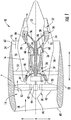
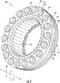
- FIGS. 2 and 3 views are provided of a combustor assembly 100 for a gas turbine engine in accordance with an exemplary embodiment of the present disclosure.
- the combustor assembly 100 of FIGS. 2 and 3 may be positioned in the combustion section 26 of the exemplary turbofan engine 10 of FIG. 1 , which defines an axial direction A, a radial direction R, and a circumferential direction C.
- FIG. 2 provides a perspective view of the combustor assembly 100
- FIG. 3 provides a side, schematic, cross-sectional view of the exemplary combustor assembly 100 of FIG. 2 .
- the combustor assembly 100 generally includes a combustor dome 102 and a combustion chamber liner.
- the combustion chamber liner is configured as a combustion chamber outer liner 104, and the combustor dome 102 and combustion chamber outer liner 104 are formed integrally of a ceramic matrix composite ("CMC") material.
- CMC material is a non-metallic material having high temperature capability.
- Exemplary CMC materials utilized for the combustor dome 102 and combustion chamber liners may include silicon carbide, silicon, silica or alumina matrix materials and combinations thereof.
- Ceramic fibers may be embedded within the matrix, such as oxidation stable reinforcing fibers including monofilaments like sapphire and silicon carbide (e.g., Textron's SCS-6), as well as rovings and yarn including silicon carbide (e.g., Nippon Carbon's NICALON®, Ube Industries' TYRANNO®, and Dow Corning's SYLRAMIC®), alumina silicates (e.g., Nextel's 440 and 480), and chopped whiskers and fibers (e.g., Nextel's 440 and SAFFIL®), and optionally ceramic particles (e.g., oxides of Si, Al, Zr, Y and combinations thereof) and inorganic fillers (e.g., pyrophyllite, wollastonite, mica, talc, kyanite and montmorillonite).
- oxidation stable reinforcing fibers including monofilaments like sapphire and silicon carbide (e.g., Textr
- the combustor dome 102 and combustion chamber outer liner 104 extend along the circumferential direction C and are formed integrally of a single, continuously formed piece of CMC material. More particularly, the combustor dome 102 and combustion chamber outer liner 104 each extend continuously along the circumferential direction C to define an annular shape, without any seams or joints where separate pieces are combined by, e.g., bolting. It will be appreciated that as used herein, a CMC component form integrally of a single, continuously formed piece of CMC material includes a component formed of overlapping and non-overlapping strips or sheets of CMC formed together using a resin or other suitable joining compound.
- combustor assembly 100 additionally includes a combustion chamber inner liner 106. Similar to the combustor dome 102 and combustion chamber outer liner 104, the combustion chamber inner liner 106 also extends continuously along the circumferential direction C to define an annular shape. As will be discussed in greater detail below, the combustion chamber inner liner 106 is joined to the combustor dome 102, such that the combustion chamber inner liner 106 and the integrally formed combustion chamber outer liner 104 and combustor dome 102 together define an annular combustion chamber 108. Accordingly, the exemplary combustor assembly 100 depicted is configured as an annular combustor.
- the combustion chamber outer liner 104 and combustion chamber inner liner 106 each extend generally along the axial direction A-the combustion chamber outer liner 104 extending between a forward end 110 and an aft end 112 and the combustion chamber inner liner 106 similarly extending between a forward end 114 and an aft end 116.
- the combustor dome 102 includes a forward wall 118 and a transition portion.
- the combustor dome 102 depicted includes an outer transition portion 120 and an inner transition portion 122.
- the outer transition portion 120 is positioned along an outer edge of the forward wall 118 along the radial direction R and the inner transition portion 122 is positioned along an inner edge of the forward wall 118 along the radial direction R.
- the inner and outer transition portions 122, 120 each extend circumferentially with the forward wall 118 of the combustor dome 102 (see a FIG. 2 ).
- the outer transition portion 120 extends from the forward wall 118 towards the outer liner 104 and the inner transition portion 122 extends from the forward wall 118 towards the inner liner 106.
- the outer liner 104 is formed integrally with the combustor dome 102 (including the forward wall 118 and the outer transition portion 120), and thus the outer transition portion 120 extends seamlessly from the forward wall 118 to the outer liner 104.
- the combustor dome 102 and combustion chamber outer liner 104 together define a continuous and seamless surface extending from the combustor dome 102 to the combustion chamber outer liner 104. More particularly, the combustor dome 102 and combustion chamber outer liner 104 together define a continuous and seamless inside surface 124 (i.e., facing the combustion chamber 108) and a continuous and seamless outside surface 126 (opposite the inside surface 124).
- the outer transition portion 120 and inner transition portion 122 each define an angle relative to the forward wall 118.
- the outer transition portion 120 and inner transition portion 122 each define an angle 132, 133, respectively, greater than ninety degrees (90°) and less than one hundred and eighty degrees (180°) relative to the forward wall 118.
- the outer transition portion 120 includes a flat 128 (i.e., a substantially flat portion as viewed in the cross-sectional plane depicted in FIG. 4 ) and the inner transition portion 122 similarly includes a flat 130.
- the flats 128, 130 of the outer transition portion 120 and inner transition portion 122 each define an angle 132, 133 greater than ninety degrees (90°) and less than one hundred and eighty degrees (180°) relative to the forward wall 118.
- the angles 132, 133 of the flats 120, 130 relative to the forward wall 118 is between about one hundred and twenty degrees (120°) and one hundred and fifty degrees (150°), such as about one hundred and thirty-five degrees (135°). It should be appreciated, that as used herein, terms of approximation, such as "about” or “approximately,” refer to being within a ten percent (10%) margin of error.
- the exemplary combustor dome 102 additionally defines an outer radius of curvature 134 between the outer flat 128 of the outer transition portion 120 and the forward wall 118.
- the forward wall 118 defines a length 140 between the outer flat 128 and the inner flat 130.
- the outer radius of curvature 134 may be between about two percent (2%) and about twenty percent (20%) of the length 140 of the forward wall 118.
- the outer radius of curvature 134 may be between about five percent (5%) and about fifteen percent (15%) of the length 140 of the forward wall 118, or between about eight percent (8%) and about twelve percent (12%) of the length 140 of the forward wall 118.
- the combustor dome 102 may define an inner radius of curvature 136 between the inner flat 130 of the inner transition portion 122 and the forward wall 118.
- the inner radius of curvature 136 may in certain embodiments, have the same value as the outer radius of curvature 134. It should be appreciated, that as used herein, the term "radius of curvature” refers to radius of a circle that touches a curve at a given point and has the same tangent and curvature at that point.
- the flat 128 of the outer transition portion 120 defines a length 138 and, as stated, the forward wall 118 of the combustor dome 102 also defines the length 140.
- the length 138 of the flat 128 may be between about ten percent (10%) and about thirty-five percent (35%) of the length 140 of the forward wall 118 of the combustor dome 102.
- the length 138 of the flat 128 may be between about fifteen percent (15%) and about thirty percent (30%) of the length 140 of the forward wall 118, or between about twenty percent (20%) and about twenty-five percent (25%) of the length 140 of the forward wall 118.
- the flat 130 of the inner transition portion 122 also defines a length 142 in the cross-sectional plane depicted.
- the length 142 of the flat 130 of the inner transition portion 122 may also be between about ten percent (10%) and about thirty-five percent (35%) of the length 140 of the forward wall 118 of the combustor dome 102.
- the length 142 of the flat 130 may be between about fifteen percent (15%) and about thirty percent (30%) of the length 140 of the forward wall 118, or between about twenty percent (20%) and about twenty-five percent (25%) of the length 140 of the forward wall 118.
- a combustor assembly in accordance with one or more embodiments of the present disclosure may provide for desirable flow characteristics through the combustion chamber as well as around the combustion chamber (e.g., for cooling air flowing around the combustion chamber).
- inclusion of an integrally formed combustion chamber outer liner and combustor dome, and/or inclusion of one or more of the inner and outer transition portions with the combustor dome may allow for more desirable flow characteristics of combustion gasses through the combustion chamber and to a turbine section of a gas turbine engine into which the combustor assembly is installed, as well as around the combustion chamber.
- inclusion of the transition portions in accordance with an embodiment of the present disclosure may allow cooling flow along a hot side of the dome to blend with a cooling flow along a hot side of the liners (introduced through one or more cooling holes on the liners). Such a configuration may thus allow for a cooling flow over portions of the transition portions where no cooling holes may be present. Additionally, inclusion of the transition portions in accordance with an embodiment of the present disclosure may allow smoother cooling flow over the cold sides of the combustor dome and combustor liners, which may provide for less pressure drop for a cooling air provided to downstream cooling holes in the combustor liners.
- configuring the combustor dome, combustion chamber inner liner, and combustion chamber outer liner to each extend continuously along a circumferential direction may further increase the desirable flow characteristics of the combustion gases through the combustion chamber by eliminating any seams (such as any axially extending seams) between circumferentially spaced segments and by allowing for uniform thermal expansion and contraction during operation of the combustor assembly.
- the exemplary combustor assembly 100 depicted in FIGS. 2 through 4 , and described herein, are provided by way of example only and that in other exemplary embodiments of the present disclosure, the combustor assembly 100 may have any other suitable configuration.
- the combustion chamber outer liner 104 may not be formed integrally with the combustor dome 102, and instead may be attached to the combustor dome 102 in any suitable manner.
- the combustion chamber inner liner 106 may be integrally formed with the combustor dome 102 instead of or in addition to the combustion chamber outer liner 104.
- the combustor dome 102 may have any other suitable configuration.
- the combustor dome 102 may not include one or both of the outer transition portion 120 or the inner transition portion 122.
- one or both of the outer transition portion 120 or the inner transition portion 122 may be configured in any other suitable manner.
- the outer transition portion 120 of the combustor dome 102 is formed integrally with and extends seamlessly into the combustion chamber outer liner 104.
- the combustion chamber inner liner 106 is formed separately from the combustor dome 102 and combustion chamber outer liner 104.
- the combustion chamber inner liner 106 is attached to the combustor dome 102 using a bolt 144.
- the combustion chamber inner liner 106 includes an attachment flange 146 extending inward along the radial direction R at the forward end 114 and the combustor dome 102 similarly includes an attachment flange 148 extending inward along the radial direction R at a radially inner end.
- the bolt 144 extends through the flange 146 of the combustion chamber inner liner 106 and the flange 148 of the combustor dome 102 to attach the two components.
- the combustion chamber inner liner 106 and combustor dome 102 abut at an inner surface (i.e., facing the combustion chamber 108) to define a substantially continuous surface, with the exception of a single seam 150 extending circumferentially where the two components are joined.
- the bolt 144 is configured as part of a mounting assembly 152 of the combustor assembly 100.
- the mounting assembly 152 generally includes a support member 145 extending generally between a forward end 147 and an aft end 149, attaching to the combustion chamber inner liner 106 and combustor dome 102 at the forward end 147.
- the support member is mountable to, e.g., a casing or other support structure within the gas turbine engine.
- combustion chamber outer liner 104, combustor dome 102, and combustion chamber inner liner 106 may each be supported within the gas turbine engine at a forward end of the combustor assembly 100 (i.e., at the forward end 114 of the inner liner 106) through the support member 145 of the mounting assembly 152.
- the combustor dome 102 additionally defines an opening 154 and the combustor assembly 100 includes a fuel-air injector hardware assembly 156. More particularly, the combustor dome 102 defines a plurality of openings 154 and the combustor assembly 100 includes a respective plurality of fuel-air injector hardware assemblies 156-each opening 154 configured for receiving a respective one of the plurality of fuel-air injector hardware assemblies 156.
- each of the openings 154 are substantially evenly spaced along the circumferential direction C, or more particularly are substantially evenly spaced from one another along the circumferential direction C.
- the plurality of fuel-air injector hardware assemblies 156 may each include, e.g., a swirler and/or a baffle. Generally, the fuel-air injector hardware assemblies 156 are configured to receive a flow of combustible fuel from a fuel nozzle (not shown) and compressed air from a compressor section of a gas turbine engine in which the combustor assembly 100 is installed (see FIG. 1 ). The fuel-air injector hardware assemblies 156 mix the fuel and compressed air and provide such fuel-air mixture to the combustion chamber 108. Although not depicted, an igniter may extend at least partially into the combustion chamber 108 to initially ignite the fuel-air mixture.
- each fuel-air injector hardware assembly 156 is attached directly to the combustor dome 102 and a respective one of the plurality of openings 154. Additionally, as is depicted, each fuel-air injector hardware assembly 156 extends into or through such opening 154. More particularly, the combustor dome 102 defines a hot side 158 exposed to the combustion chamber 108 and an opposite cold side 160. Although not depicted, combustor dome may include a protective coating, such as an environmental protective coating, at the hot side 158 and/or the cold side 160.
- the combustor dome 102 includes a raised boss 162 extending around each of the plurality of openings 154 in the combustor dome 102 on the cold side 160 of the combustor dome 102, and a groove 164 extending around each of the plurality openings 154 in the combustor dome 102 on the hot side 158 of the combustor dome 102.
- the raised boss 162 and groove 164 of the combustor dome 102 are configured for assisting with mounting the fuel-air injector hardware assemblies 156 directly to the combustor dome 102.
- the raised boss 162 allows for a desired thickness, such that the fuel-air injector hardware assemblies 156 may be attached directly to the combustor dome 102.
- the fuel-air injector hardware assemblies 156 are each attached directly to the hot side 158 of the combustor dome 102 (i.e., at the groove 164) and to the cold side 160 of the combustor dome 102 (i.e., at the raised boss 162).
- the fuel-air injector hardware assemblies 156 are each attached directly to the hot side 158 of the combustor dome 102 (i.e., at the groove 164) and to the cold side 160 of the combustor dome 102 (i.e., at the raised boss 162).
- At least one of the fuel-air injector hardware assemblies 156 is attached directly to the combustor dome 102 independently of an adjacent fuel-air injector hardware assembly 156, or more specifically each of the fuel-air injector hardware assemblies 156 are attached directly to the combustor dome 102 independently of the adjacent fuel-air injector hardware assemblies 156.
- the combustor assembly 100 depicted includes a combustor dome 102 extending continuously along the circumferential direction C, no additional or supplemental supports are required for the combustor dome 102 and plurality of fuel-air injector hardware assemblies 156.
- the combustor dome 102 defines a plurality of cooling holes 166 extending through the combustor dome 102 from the cold side 160 to the hot side 158 to allow for a flow of cooling air therethrough.
- the plurality of cooling holes 166 includes a plurality of cooling holes extending around and encircling at least one of the openings 154 defined in the combustor dome 102 for receiving the respective fuel-air injector hardware assemblies 156.
- the plurality of cooling holes 166 include a plurality of cooling holes extending around and encircling each of the openings 154 defined in the combustor dome 102.
- the combustor dome 102 includes a variety of additional cooling holes 166 defined in the forward wall 118 of the combustor dome 102. Further, the combustor dome 102 defines a plurality of cooling holes 166 extending through the outer transition portion 120 of the combustor dome 102 and the inner transition portion 122 of the combustor dome 102 (see, e.g., FIG. 3 ) from the cold side 160 to the hot side 158 to allow for a flow of cooling air therethrough. Moreover, the combustion chamber outer liner 104 includes a plurality of cooling holes 166 extending therethrough in a similar manner to allow for an additional amount of cooling air to flow therethrough. The cooling air may be provided from a compressor section of a gas turbine engine into which the combustor assembly 100 is installed.
- Inclusion of an integrally formed combustion chamber liner and combustor dome, and/or a combustor dome having one or both of an inner transition portion or outer transition portion, may allow for direct localized cooling of certain areas of the components forming the combustion chamber without substantially disrupting a flow of combustion gasses through the combustion chamber.
- the combustor assembly 100 may have any other suitable configuration.
- the fuel-air injector hardware assemblies 156 may be configured in any other suitable manner, and also may be attached to the combustor dome 102 in any other suitable manner.
- one or more of the combustion chamber outer liner 104, combustor dome 102, and combustion chamber inner liner 106 may have any other suitable configuration of cooling holes 166 or other cooling means for maintaining a temperature of such components within a desired temperature range.
Abstract
Description
- The present subject matter relates generally to a gas turbine engine, or more particularly to a combustor assembly for a gas turbine engine.
- A gas turbine engine generally includes a fan and a core arranged in flow communication with one another. Additionally, the core of the gas turbine engine general includes, in serial flow order, a compressor section, a combustion section, a turbine section, and an exhaust section. In operation, air is provided from the fan to an inlet of the compressor section where one or more axial compressors progressively compress the air until it reaches the combustion section. Fuel is mixed with the compressed air and burned within the combustion section to provide combustion gases. The combustion gases are routed from the combustion section to the turbine section. The flow of combustion gasses through the turbine section drives the turbine section and is then routed through the exhaust section, e.g., to atmosphere.
- More commonly, non-traditional high temperature materials, such as ceramic matrix composite (CMC) materials, are being used as structural components within gas turbine engines. For example, typical combustion sections include an inner liner, an outer liner, and a dome. More commonly, the inner and outer liners are being formed of CMC materials, while the dome is formed of a metal material. The metal dome has conventionally been required to attach certain fuel-air injection assemblies.
- However, certain gas turbine engines have had problems accommodating certain mechanical properties of the CMC materials incorporated therein. For example, CMC materials have different coefficients of thermal expansion than the traditional metal materials. Therefore, the attachment of the inner and outer liners, formed of a CMC material, to the dome, formed of a metal material, may require a fairly complicated attachment assembly. Such attachment assemblies may create aerodynamic hurdles for a flow of combustion gasses through the combustion chamber. For example, such attachment assemblies may disrupt a flow of combustion gasses through the combustion chamber. Accordingly, a combustor assembly capable of utilizing CMC materials while improving the aerodynamics within the combustion chamber would be useful.
- Aspects and advantages of the invention will be set forth in part in the following description, or may be obvious from the description, or may be learned through practice of the invention.
- In one exemplary embodiment of the present disclosure, a combustor assembly for a gas turbine engine defining a circumferential direction is provided. The combustor assembly includes a liner and a combustor dome. The combustor dome and the liner together at least in part define a combustion chamber. Additionally, the combustor dome includes a transition potion and a forward wall. The transition portion defines an angle greater than 90 degrees and less than 180 relative to the forward wall. Additionally, the transition portion extends from the forward wall towards the liner.
- In another exemplary embodiment of the present disclosure a combustor assembly for a gas turbine engine defining a circumferential direction is provided. The combustor assembly includes a liner and a combustor dome. The combustor dome and the liner together at least in part define a combustion chamber. The combustor dome includes a transition potion and a forward wall. The forward wall defines a length. The transition portion includes a flat extending from the forward wall towards the liner and defines a radius of curvature between the forward wall and the flat of the transition portion between about two percent and about twenty percent of the length of the forward wall.
- These and other features, aspects and advantages of the present invention will become better understood with reference to the following description and appended claims. The accompanying drawings, which are incorporated in and constitute a part of this specification, illustrate embodiments of the invention and, together with the description, serve to explain the principles of the invention.
- A full and enabling disclosure of the present invention, including the best mode thereof, directed to one of ordinary skill in the art, is set forth in the specification, which makes reference to the appended figures, in which:
-
FIG. 1 is a schematic cross-sectional view of an exemplary gas turbine engine according to various embodiments of the present subject matter. -
FIG. 2 is a perspective view of a combustor assembly in accordance with an exemplary embodiment of the present disclosure. -
FIG. 3 is a side, cross-sectional view of the exemplary combustor assembly ofFIG. 2 . -
FIG. 4 is a close-up, side, cross-sectional view of the exemplary combustor assembly ofFIG. 2 . -
FIG. 5 is a close-up, side, cross-sectional view of an opening in a combustor dome of the exemplary combustor assembly ofFIG. 2 . - Reference will now be made in detail to present embodiments of the invention, one or more examples of which are illustrated in the accompanying drawings. The detailed description uses numerical and letter designations to refer to features in the drawings. Like or similar designations in the drawings and description have been used to refer to like or similar parts of the invention. As used herein, the terms "first", "second", and "third" may be used interchangeably to distinguish one component from another and are not intended to signify location or importance of the individual components. The terms "upstream" and "downstream" refer to the relative direction with respect to fluid flow in a fluid pathway. For example, "upstream" refers to the direction from which the fluid flows, and "downstream" refers to the direction to which the fluid flows.
- Referring now to the drawings, wherein identical numerals indicate the same elements throughout the figures,
FIG. 1 is a schematic cross-sectional view of a gas turbine engine in accordance with an exemplary embodiment of the present disclosure. More particularly, for the embodiment ofFIG. 1 , the gas turbine engine is a high-bypassturbofan jet engine 10, referred to herein as "turbofan engine 10." As shown inFIG. 1 , theturbofan engine 10 defines an axial direction A (extending parallel to alongitudinal centerline 12 provided for reference), a radial direction R, and a circumferential direction (not shown) extending about the axial direction A. In general, theturbofan 10 includes afan section 14 and acore turbine engine 16 disposed downstream from thefan section 14. - The exemplary
core turbine engine 16 depicted generally includes a substantially tubularouter casing 18 that defines anannular inlet 20. Theouter casing 18 encases and thecore turbine engine 16 includes, in serial flow relationship, a compressor section including a booster or low pressure (LP)compressor 22 and a high pressure (HP)compressor 24; acombustion section 26; a turbine section including a high pressure (HP)turbine 28 and a low pressure (LP)turbine 30; and a jetexhaust nozzle section 32. A high pressure (HP) shaft orspool 34 drivingly connects the HPturbine 28 to the HPcompressor 24. A low pressure (LP) shaft orspool 36 drivingly connects theLP turbine 30 to theLP compressor 22. The compressor section,combustion section 26, turbine section, andnozzle section 32 together define acore air flowpath 37. - For the embodiment depicted, the
fan section 14 includes avariable pitch fan 38 having a plurality offan blades 40 coupled to adisk 42 in a spaced apart manner. As depicted, thefan blades 40 extend outwardly fromdisk 42 generally along the radial direction R. Eachfan blade 40 is rotatable relative to thedisk 42 about a pitch axis P by virtue of thefan blades 40 being operatively coupled to a suitablepitch change mechanism 44 configured to collectively vary the pitch of thefan blades 40 in unison. Thefan blades 40,disk 42, andpitch change mechanism 44 are together rotatable about thelongitudinal axis 12 byLP shaft 36 across apower gear box 46. Thepower gear box 46 includes a plurality of gears for adjusting the rotational speed of thefan 38 relative to theLP shaft 36 to a more efficient rotational fan speed. - Referring still to the exemplary embodiment of
FIG. 1 , thedisk 42 is covered by arotatable front hub 48 aerodynamically contoured to promote an airflow through the plurality offan blades 40. Additionally, theexemplary fan section 14 includes an annular fan casing orouter nacelle 50 that circumferentially surrounds thefan 38 and/or at least a portion of thecore turbine engine 16. Theexemplary nacelle 50 is supported relative to thecore turbine engine 16 by a plurality of circumferentially-spacedoutlet guide vanes 52. Moreover, adownstream section 54 of thenacelle 50 extends over an outer portion of thecore turbine engine 16 so as to define abypass airflow passage 56 therebetween. - During operation of the
turbofan engine 10, a volume ofair 58 enters theturbofan 10 through an associatedinlet 60 of thenacelle 50 and/orfan section 14. As the volume ofair 58 passes across thefan blades 40, a first portion of theair 58 as indicated byarrows 62 is directed or routed into thebypass airflow passage 56 and a second portion of theair 58 as indicated byarrow 64 is directed or routed into thecore air flowpath 37, or more specifically into theLP compressor 22. The ratio between the first portion ofair 62 and the second portion ofair 64 is commonly known as a bypass ratio. The pressure of the second portion ofair 64 is then increased as it is routed through the high pressure (HP)compressor 24 and into thecombustion section 26, where it is mixed with fuel and burned to providecombustion gases 66. - The
combustion gases 66 are routed through theHP turbine 28 where a portion of thermal and/or kinetic energy from thecombustion gases 66 is extracted via sequential stages of HP turbine stator vanes 68 that are coupled to theouter casing 18 and HPturbine rotor blades 70 that are coupled to the HP shaft orspool 34, thus causing the HP shaft orspool 34 to rotate, thereby supporting operation of theHP compressor 24. Thecombustion gases 66 are then routed through theLP turbine 30 where a second portion of thermal and kinetic energy is extracted from thecombustion gases 66 via sequential stages of LPturbine stator vanes 72 that are coupled to theouter casing 18 and LPturbine rotor blades 74 that are coupled to the LP shaft orspool 36, thus causing the LP shaft orspool 36 to rotate, thereby supporting operation of theLP compressor 22 and/or rotation of thefan 38. - The
combustion gases 66 are subsequently routed through the jetexhaust nozzle section 32 of thecore turbine engine 16 to provide propulsive thrust. Simultaneously, the pressure of the first portion ofair 62 is substantially increased as the first portion ofair 62 is routed through thebypass airflow passage 56 before it is exhausted from a fannozzle exhaust section 76 of theturbofan 10, also providing propulsive thrust. TheHP turbine 28, theLP turbine 30, and the jetexhaust nozzle section 32 at least partially define ahot gas path 78 for routing thecombustion gases 66 through thecore turbine engine 16. - It should be appreciated, however, that the
exemplary turbofan engine 10 depicted inFIG. 1 is provided by way of example only, and that in other exemplary embodiments, theturbofan engine 10 may have any other suitable configuration. It should also be appreciated, that in still other exemplary embodiments, aspects of the present disclosure may be incorporated into any other suitable gas turbine engine. For example, in other exemplary embodiments, aspects of the present disclosure may be incorporated into, e.g., a turboprop engine, a turboshaft engine, or a turbojet engine. - Referring now to
FIGS. 2 and3 , views are provided of acombustor assembly 100 for a gas turbine engine in accordance with an exemplary embodiment of the present disclosure. For example, thecombustor assembly 100 ofFIGS. 2 and3 may be positioned in thecombustion section 26 of theexemplary turbofan engine 10 ofFIG. 1 , which defines an axial direction A, a radial direction R, and a circumferential direction C. More particularly,FIG. 2 provides a perspective view of thecombustor assembly 100 andFIG. 3 provides a side, schematic, cross-sectional view of theexemplary combustor assembly 100 ofFIG. 2 . - As shown, the
combustor assembly 100 generally includes acombustor dome 102 and a combustion chamber liner. For the embodiment depicted, the combustion chamber liner is configured as a combustion chamberouter liner 104, and thecombustor dome 102 and combustion chamberouter liner 104 are formed integrally of a ceramic matrix composite ("CMC") material. CMC material is a non-metallic material having high temperature capability. Exemplary CMC materials utilized for thecombustor dome 102 and combustion chamber liners (e.g., the outer liner 104) may include silicon carbide, silicon, silica or alumina matrix materials and combinations thereof. Ceramic fibers may be embedded within the matrix, such as oxidation stable reinforcing fibers including monofilaments like sapphire and silicon carbide (e.g., Textron's SCS-6), as well as rovings and yarn including silicon carbide (e.g., Nippon Carbon's NICALON®, Ube Industries' TYRANNO®, and Dow Corning's SYLRAMIC®), alumina silicates (e.g., Nextel's 440 and 480), and chopped whiskers and fibers (e.g., Nextel's 440 and SAFFIL®), and optionally ceramic particles (e.g., oxides of Si, Al, Zr, Y and combinations thereof) and inorganic fillers (e.g., pyrophyllite, wollastonite, mica, talc, kyanite and montmorillonite). - Additionally, the
combustor dome 102 and combustion chamberouter liner 104 extend along the circumferential direction C and are formed integrally of a single, continuously formed piece of CMC material. More particularly, thecombustor dome 102 and combustion chamberouter liner 104 each extend continuously along the circumferential direction C to define an annular shape, without any seams or joints where separate pieces are combined by, e.g., bolting. It will be appreciated that as used herein, a CMC component form integrally of a single, continuously formed piece of CMC material includes a component formed of overlapping and non-overlapping strips or sheets of CMC formed together using a resin or other suitable joining compound. - As may be seen most clearly in
FIG. 3 ,combustor assembly 100 additionally includes a combustion chamberinner liner 106. Similar to thecombustor dome 102 and combustion chamberouter liner 104, the combustion chamberinner liner 106 also extends continuously along the circumferential direction C to define an annular shape. As will be discussed in greater detail below, the combustion chamberinner liner 106 is joined to thecombustor dome 102, such that the combustion chamberinner liner 106 and the integrally formed combustion chamberouter liner 104 andcombustor dome 102 together define anannular combustion chamber 108. Accordingly, theexemplary combustor assembly 100 depicted is configured as an annular combustor. - Referring to
FIG. 3 in particular, the combustion chamberouter liner 104 and combustion chamberinner liner 106 each extend generally along the axial direction A-the combustion chamberouter liner 104 extending between aforward end 110 and anaft end 112 and the combustion chamberinner liner 106 similarly extending between aforward end 114 and anaft end 116. Additionally, thecombustor dome 102 includes aforward wall 118 and a transition portion. Specifically, thecombustor dome 102 depicted includes anouter transition portion 120 and aninner transition portion 122. Theouter transition portion 120 is positioned along an outer edge of theforward wall 118 along the radial direction R and theinner transition portion 122 is positioned along an inner edge of theforward wall 118 along the radial direction R. The inner andouter transition portions forward wall 118 of the combustor dome 102 (see aFIG. 2 ). - Further, the
outer transition portion 120 extends from theforward wall 118 towards theouter liner 104 and theinner transition portion 122 extends from theforward wall 118 towards theinner liner 106. As stated, for the embodiment depicted theouter liner 104 is formed integrally with the combustor dome 102 (including theforward wall 118 and the outer transition portion 120), and thus theouter transition portion 120 extends seamlessly from theforward wall 118 to theouter liner 104. For example, thecombustor dome 102 and combustion chamberouter liner 104 together define a continuous and seamless surface extending from thecombustor dome 102 to the combustion chamberouter liner 104. More particularly, thecombustor dome 102 and combustion chamberouter liner 104 together define a continuous and seamless inside surface 124 (i.e., facing the combustion chamber 108) and a continuous and seamless outside surface 126 (opposite the inside surface 124). - Referring now briefly to
FIG. 4 , providing a close-up, cross-sectional, schematic view of a forward end of thecombustor assembly 100 ofFIGS. 2 and3 , theouter transition portion 120 andinner transition portion 122 each define an angle relative to theforward wall 118. For the embodiment depicted, theouter transition portion 120 andinner transition portion 122 each define anangle forward wall 118. More specifically, theouter transition portion 120 includes a flat 128 (i.e., a substantially flat portion as viewed in the cross-sectional plane depicted inFIG. 4 ) and theinner transition portion 122 similarly includes a flat 130. Theflats outer transition portion 120 andinner transition portion 122, respectively, each define anangle forward wall 118. Specifically, for the embodiment depicted, theangles flats forward wall 118 is between about one hundred and twenty degrees (120°) and one hundred and fifty degrees (150°), such as about one hundred and thirty-five degrees (135°). It should be appreciated, that as used herein, terms of approximation, such as "about" or "approximately," refer to being within a ten percent (10%) margin of error. - As may also be seen in
FIG. 4 , theexemplary combustor dome 102 additionally defines an outer radius ofcurvature 134 between the outer flat 128 of theouter transition portion 120 and theforward wall 118. Notably, theforward wall 118 defines a length 140 between the outer flat 128 and the inner flat 130. In certain exemplary embodiments, the outer radius ofcurvature 134 may be between about two percent (2%) and about twenty percent (20%) of the length 140 of theforward wall 118. For example, the outer radius ofcurvature 134 may be between about five percent (5%) and about fifteen percent (15%) of the length 140 of theforward wall 118, or between about eight percent (8%) and about twelve percent (12%) of the length 140 of theforward wall 118. Similarly, thecombustor dome 102 may define an inner radius ofcurvature 136 between the inner flat 130 of theinner transition portion 122 and theforward wall 118. The inner radius ofcurvature 136 may in certain embodiments, have the same value as the outer radius ofcurvature 134. It should be appreciated, that as used herein, the term "radius of curvature" refers to radius of a circle that touches a curve at a given point and has the same tangent and curvature at that point. - Moreover, in the cross-sectional plane depicted in
FIG. 4 , the flat 128 of theouter transition portion 120 defines alength 138 and, as stated, theforward wall 118 of thecombustor dome 102 also defines the length 140. Thelength 138 of the flat 128 may be between about ten percent (10%) and about thirty-five percent (35%) of the length 140 of theforward wall 118 of thecombustor dome 102. For example, thelength 138 of the flat 128 may be between about fifteen percent (15%) and about thirty percent (30%) of the length 140 of theforward wall 118, or between about twenty percent (20%) and about twenty-five percent (25%) of the length 140 of theforward wall 118. Further, as is depicted, the flat 130 of theinner transition portion 122 also defines alength 142 in the cross-sectional plane depicted. Thelength 142 of the flat 130 of theinner transition portion 122 may also be between about ten percent (10%) and about thirty-five percent (35%) of the length 140 of theforward wall 118 of thecombustor dome 102. For example, thelength 142 of the flat 130 may be between about fifteen percent (15%) and about thirty percent (30%) of the length 140 of theforward wall 118, or between about twenty percent (20%) and about twenty-five percent (25%) of the length 140 of theforward wall 118. - A combustor assembly in accordance with one or more embodiments of the present disclosure may provide for desirable flow characteristics through the combustion chamber as well as around the combustion chamber (e.g., for cooling air flowing around the combustion chamber). Specifically, inclusion of an integrally formed combustion chamber outer liner and combustor dome, and/or inclusion of one or more of the inner and outer transition portions with the combustor dome, may allow for more desirable flow characteristics of combustion gasses through the combustion chamber and to a turbine section of a gas turbine engine into which the combustor assembly is installed, as well as around the combustion chamber. For example, inclusion of the transition portions in accordance with an embodiment of the present disclosure may allow cooling flow along a hot side of the dome to blend with a cooling flow along a hot side of the liners (introduced through one or more cooling holes on the liners). Such a configuration may thus allow for a cooling flow over portions of the transition portions where no cooling holes may be present. Additionally, inclusion of the transition portions in accordance with an embodiment of the present disclosure may allow smoother cooling flow over the cold sides of the combustor dome and combustor liners, which may provide for less pressure drop for a cooling air provided to downstream cooling holes in the combustor liners. Further, configuring the combustor dome, combustion chamber inner liner, and combustion chamber outer liner to each extend continuously along a circumferential direction may further increase the desirable flow characteristics of the combustion gases through the combustion chamber by eliminating any seams (such as any axially extending seams) between circumferentially spaced segments and by allowing for uniform thermal expansion and contraction during operation of the combustor assembly.
- It should be appreciated, however, that the
exemplary combustor assembly 100 depicted inFIGS. 2 through 4 , and described herein, are provided by way of example only and that in other exemplary embodiments of the present disclosure, thecombustor assembly 100 may have any other suitable configuration. For example, in other exemplary embodiments, the combustion chamberouter liner 104 may not be formed integrally with thecombustor dome 102, and instead may be attached to thecombustor dome 102 in any suitable manner. Further, in certain exemplary embodiments, the combustion chamberinner liner 106 may be integrally formed with thecombustor dome 102 instead of or in addition to the combustion chamberouter liner 104. Moreover, in still other embodiments, thecombustor dome 102 may have any other suitable configuration. For example, in certain embodiments, thecombustor dome 102 may not include one or both of theouter transition portion 120 or theinner transition portion 122. Or alternatively, one or both of theouter transition portion 120 or theinner transition portion 122 may be configured in any other suitable manner. - Referring again to
FIGS. 2 and3 , theouter transition portion 120 of thecombustor dome 102, as stated, is formed integrally with and extends seamlessly into the combustion chamberouter liner 104. By contrast, however, for the embodiment depicted the combustion chamberinner liner 106 is formed separately from thecombustor dome 102 and combustion chamberouter liner 104. The combustion chamberinner liner 106 is attached to thecombustor dome 102 using abolt 144. Specifically, the combustion chamberinner liner 106 includes anattachment flange 146 extending inward along the radial direction R at theforward end 114 and thecombustor dome 102 similarly includes anattachment flange 148 extending inward along the radial direction R at a radially inner end. Thebolt 144 extends through theflange 146 of the combustion chamberinner liner 106 and theflange 148 of thecombustor dome 102 to attach the two components. Notably, the combustion chamberinner liner 106 andcombustor dome 102 abut at an inner surface (i.e., facing the combustion chamber 108) to define a substantially continuous surface, with the exception of asingle seam 150 extending circumferentially where the two components are joined. - The
bolt 144 is configured as part of a mountingassembly 152 of thecombustor assembly 100. The mountingassembly 152 generally includes asupport member 145 extending generally between aforward end 147 and anaft end 149, attaching to the combustion chamberinner liner 106 andcombustor dome 102 at theforward end 147. At theaft end 149, the support member is mountable to, e.g., a casing or other support structure within the gas turbine engine. Accordingly, the combustion chamberouter liner 104,combustor dome 102, and combustion chamberinner liner 106 may each be supported within the gas turbine engine at a forward end of the combustor assembly 100 (i.e., at theforward end 114 of the inner liner 106) through thesupport member 145 of the mountingassembly 152. - Referring still to
FIGS. 2 and3 , thecombustor dome 102 additionally defines anopening 154 and thecombustor assembly 100 includes a fuel-airinjector hardware assembly 156. More particularly, thecombustor dome 102 defines a plurality ofopenings 154 and thecombustor assembly 100 includes a respective plurality of fuel-air injector hardware assemblies 156-eachopening 154 configured for receiving a respective one of the plurality of fuel-airinjector hardware assemblies 156. For the embodiment depicted, each of theopenings 154 are substantially evenly spaced along the circumferential direction C, or more particularly are substantially evenly spaced from one another along the circumferential direction C. - The plurality of fuel-air
injector hardware assemblies 156 may each include, e.g., a swirler and/or a baffle. Generally, the fuel-airinjector hardware assemblies 156 are configured to receive a flow of combustible fuel from a fuel nozzle (not shown) and compressed air from a compressor section of a gas turbine engine in which thecombustor assembly 100 is installed (seeFIG. 1 ). The fuel-airinjector hardware assemblies 156 mix the fuel and compressed air and provide such fuel-air mixture to thecombustion chamber 108. Although not depicted, an igniter may extend at least partially into thecombustion chamber 108 to initially ignite the fuel-air mixture. - Referring now also to
FIG. 5 , providing a close-up, cross-sectional, schematic view of thecombustor dome 102 and a fuelinjector hardware assembly 156, for the embodiment depicted, each fuel-airinjector hardware assembly 156 is attached directly to thecombustor dome 102 and a respective one of the plurality ofopenings 154. Additionally, as is depicted, each fuel-airinjector hardware assembly 156 extends into or throughsuch opening 154. More particularly, thecombustor dome 102 defines ahot side 158 exposed to thecombustion chamber 108 and an oppositecold side 160. Although not depicted, combustor dome may include a protective coating, such as an environmental protective coating, at thehot side 158 and/or thecold side 160. Thecombustor dome 102 includes a raisedboss 162 extending around each of the plurality ofopenings 154 in thecombustor dome 102 on thecold side 160 of thecombustor dome 102, and agroove 164 extending around each of theplurality openings 154 in thecombustor dome 102 on thehot side 158 of thecombustor dome 102. The raisedboss 162 and groove 164 of thecombustor dome 102 are configured for assisting with mounting the fuel-airinjector hardware assemblies 156 directly to thecombustor dome 102. - Specifically, the raised
boss 162 allows for a desired thickness, such that the fuel-airinjector hardware assemblies 156 may be attached directly to thecombustor dome 102. For example, as is depicted the fuel-airinjector hardware assemblies 156 are each attached directly to thehot side 158 of the combustor dome 102 (i.e., at the groove 164) and to thecold side 160 of the combustor dome 102 (i.e., at the raised boss 162). Notably, referring back toFIG. 2 , at least one of the fuel-airinjector hardware assemblies 156 is attached directly to thecombustor dome 102 independently of an adjacent fuel-airinjector hardware assembly 156, or more specifically each of the fuel-airinjector hardware assemblies 156 are attached directly to thecombustor dome 102 independently of the adjacent fuel-airinjector hardware assemblies 156. For example, as thecombustor assembly 100 depicted includes acombustor dome 102 extending continuously along the circumferential direction C, no additional or supplemental supports are required for thecombustor dome 102 and plurality of fuel-airinjector hardware assemblies 156. - As may also be seen most clearly in
FIG. 2 , thecombustor dome 102 defines a plurality ofcooling holes 166 extending through thecombustor dome 102 from thecold side 160 to thehot side 158 to allow for a flow of cooling air therethrough. As may be seen, the plurality of cooling holes 166 includes a plurality of cooling holes extending around and encircling at least one of theopenings 154 defined in thecombustor dome 102 for receiving the respective fuel-airinjector hardware assemblies 156. Particularly, for the embodiment depicted, the plurality ofcooling holes 166 include a plurality of cooling holes extending around and encircling each of theopenings 154 defined in thecombustor dome 102. Additionally, thecombustor dome 102 includes a variety ofadditional cooling holes 166 defined in theforward wall 118 of thecombustor dome 102. Further, thecombustor dome 102 defines a plurality ofcooling holes 166 extending through theouter transition portion 120 of thecombustor dome 102 and theinner transition portion 122 of the combustor dome 102 (see, e.g.,FIG. 3 ) from thecold side 160 to thehot side 158 to allow for a flow of cooling air therethrough. Moreover, the combustion chamberouter liner 104 includes a plurality ofcooling holes 166 extending therethrough in a similar manner to allow for an additional amount of cooling air to flow therethrough. The cooling air may be provided from a compressor section of a gas turbine engine into which thecombustor assembly 100 is installed. - Inclusion of an integrally formed combustion chamber liner and combustor dome, and/or a combustor dome having one or both of an inner transition portion or outer transition portion, may allow for direct localized cooling of certain areas of the components forming the combustion chamber without substantially disrupting a flow of combustion gasses through the combustion chamber.
- It should be appreciated, however, that the exemplary embodiment depicted in
FIGS. 2 through 5 is provided by way of example only, and that in other exemplary embodiments, thecombustor assembly 100 may have any other suitable configuration. For example, in other exemplary embodiments, the fuel-airinjector hardware assemblies 156 may be configured in any other suitable manner, and also may be attached to thecombustor dome 102 in any other suitable manner. Further, in other exemplary embodiments, one or more of the combustion chamberouter liner 104,combustor dome 102, and combustion chamberinner liner 106 may have any other suitable configuration ofcooling holes 166 or other cooling means for maintaining a temperature of such components within a desired temperature range. - This written description uses examples to disclose the invention, including the best mode, and also to enable any person skilled in the art to practice the invention, including making and using any devices or systems and performing any incorporated methods. The patentable scope of the invention is defined by the claims, and may include other examples that occur to those skilled in the art. Such other examples are intended to be within the scope of the claims if they include structural elements that do not differ from the literal language of the claims, or if they include equivalent structural elements with insubstantial differences from the literal languages of the claims.
- Various aspects and embodiments of the present invention are defined by the following numbered clauses:
- 1. A combustor assembly (100) for a gas turbine engine defining a circumferential direction (C), the combustor assembly (100) comprising:
- a liner (104, 106); and
- a combustor dome (102), the combustor dome (102) and the liner (104, 106) together at least in part defining a combustion chamber (108), the combustor dome (102) comprising a transition portion (120, 122) and a forward wall (118), the transition portion (120, 122) defining an angle (132, 133) greater than 90 degrees and less than 180 relative to the forward wall (118) and extending from the forward wall (118) towards the liner (104, 106).
- 2. The combustor assembly of clause 1, wherein the transition portion of the combustor dome is an outer transition portion of the combustor dome, wherein the combustor dome further comprises an inner transition portion, wherein the liner is an outer liner, and wherein the combustor assembly further comprises:
- an inner liner, wherein the inner transition portion defines an angle greater than 90 degrees and less than 180 relative to the forward wall and extends from the forward wall towards the inner liner.
- 3. The combustor assembly of clause 1, wherein the transition portion defines a flat extending away from the forward wall of the combustor dome.
- 4. The combustor assembly of clause 3, wherein the forward wall defines a length, wherein the combustor dome defines a radius of curvature between the flat of the transition portion and the forward wall of the combustor dome, wherein the radius of curvature is between about two percent and about twenty percent of the length of the forward wall.
- 5. The combustor assembly of clause 1, wherein the combustor dome defines a hot side and a cold side, and wherein the combustor dome defines a plurality of cooling holes extending through the transition portion of the combustor dome from the cold side to the hot side to allow for a flow of cooling air.
- 6. The combustor assembly of clause 1, wherein the combustor dome defines a plurality of openings for receiving a respective plurality of fuel-air injector hardware assemblies.
- 7. The combustor assembly of clause 1, wherein the combustor dome is formed integrally of a continuously formed piece of material.
- 8. The combustor assembly of clause 1, wherein the combustor dome extends continuously along the circumferential direction to define an annular shape.
- 9. The combustor assembly of clause1, wherein the combustor dome is formed of a ceramic matrix composite material.
- 10. The combustor assembly of clause 1, wherein the combustor dome is formed integrally with the liner of a ceramic matrix composite material.
- 11. The combustor assembly of
clause 10, wherein combustor dome and liner extend along the circumferential direction to define an annular shape. - 12. A combustor assembly for a gas turbine engine defining a circumferential direction, the combustor assembly comprising:
- a liner; and
- a combustor dome, the combustor dome and the liner together at least in part defining a combustion chamber, the combustor dome comprising a transition potion and a forward wall, the forward wall defining a length, the transition portion comprising a flat extending from the forward wall towards the liner and defining a radius of curvature between the forward wall and the flat of the transition portion between about two percent and about twenty percent of the length of the forward wall.
- 13. The combustor assembly of
clause 12, wherein the flat of the transition portion defines an angle greater than 90 degrees and less than 180 relative to the forward wall. - 14. The combustor assembly of
clause 12, wherein the transition portion of the combustor dome is an outer transition portion of the combustor dome, wherein the combustor dome further comprises an inner transition portion, wherein the liner is an outer liner, and wherein the combustor assembly further comprises:- an inner liner, wherein the inner transition portion defines an angle greater than 90 degrees and less than 180 relative to the forward wall and extends from the forward wall towards the inner liner.
- 15. The combustor assembly of
clause 12, wherein the combustor dome defines a hot side and a cold side, and wherein the combustor dome defines a plurality of cooling holes extending through the transition portion from the cold side to the hot side to allow for a flow of cooling air. - 16. The combustor assembly of
clause 12, wherein the combustor dome defines a plurality of openings for receiving a respective plurality of fuel-air injector hardware assemblies. - 17. The combustor assembly of
clause 12, wherein the combustor dome is formed integrally of a continuously formed piece of material and extends continuously along the circumferential direction to define an annular shape. - 18. The combustor assembly of
clause 12, wherein the combustor dome is formed of a ceramic matrix composite material. - 19. The combustor assembly of
clause 12, wherein the combustor dome is formed integrally with the liner of a ceramic matrix composite material. - 20. The combustor assembly of clause 19, wherein combustor dome and liner extend continuously along the circumferential direction to define an annular shape.
Claims (15)
- A combustor assembly (100) for a gas turbine engine defining a circumferential direction (C), the combustor assembly (100) comprising:a liner (104, 106); anda combustor dome (102), the combustor dome (102) and the liner (104, 106) together at least in part defining a combustion chamber (108), the combustor dome (102) comprising a transition portion (120, 122) and a forward wall (118), the transition portion (120, 122) defining an angle (132, 133) greater than 90 degrees and less than 180 relative to the forward wall (118) and extending from the forward wall (118) towards the liner (104, 106).
- The combustor assembly (100) of claim 1, wherein the transition portion of the combustor dome (102) is an outer transition portion (120) of the combustor dome (102), wherein the combustor dome (102) further comprises an inner transition portion (122), wherein the liner is an outer liner (104), and wherein the combustor assembly (100) further comprises:an inner liner (106), wherein the inner transition portion (122) defines an angle (133) greater than 90 degrees and less than 180 relative to the forward wall (118) and extends from the forward wall (118) towards the inner liner (106).
- The combustor assembly (100) of claim 1 or 2, wherein the transition portion (120, 122) defines a flat (128, 130) extending away from the forward wall (118) of the combustor dome (102).
- The combustor assembly (100) of any preceding claim, wherein the combustor dome (102) defines a hot side (158) and a cold side (160), and wherein the combustor dome (102) defines a plurality of cooling holes (166) extending through the transition portion (120, 122) of the combustor dome (102) from the cold side (160) to the hot side (158) to allow for a flow of cooling air.
- The combustor assembly (100) of any preceding claim, wherein the combustor dome (102) defines a plurality of openings (154) for receiving a respective plurality of fuel-air injector hardware assemblies (156).
- The combustor assembly (100) of any preceding claim, wherein the combustor dome (102) is formed integrally of a continuously formed piece of material, preferably of a ceramic matrix composite (CMC) material.
- The combustor assembly (100) of any preceding claim, wherein the combustor dome (102) extends continuously along the circumferential direction (C) to define an annular shape.
- The combustor assembly (100) of any preceding claim, wherein the combustor dome (102) is formed integrally with the liner (104, 106) of a ceramic matrix composite material and the combustor dome (102) and liner (104, 106) extend along the circumferential direction (C) to define an annular shape.
- A combustor assembly (100) for a gas turbine engine defining a circumferential direction (C), the combustor assembly (100) comprising:a liner (104, 106); anda combustor dome (102), the combustor dome (102) and the liner (104,106) together at least in part defining a combustion chamber (108), the combustor dome (102) comprising a transition portion (120,122) and a forward wall (118), the forward wall (118) defining a length (140), the transition portion (120, 122) comprising a flat (128, 130) extending from the forward wall (118) towards the liner (104,106) and defining a radius of curvature (134, 136) between the forward wall (118) and the flat (128, 130) of the transition portion (120, 122) between about two percent and about twenty percent of the length (140) of the forward wall (118).
- The combustor assembly of claim 9, wherein the flat (128, 130) of the transition portion (120,122) defines an angle (132,133) greater than 90 degrees and less than 180 relative to the forward wall (118).
- The combustor assembly of claim 9 or 10, wherein the transition portion of the combustor dome (102) is an outer transition portion (120) of the combustor dome (102), wherein the combustor dome (102) further comprises an inner transition portion (122), wherein the liner is an outer liner (104), and wherein the combustor assembly (100) further comprises:an inner liner (106), wherein the inner transition portion (122) defines an angle (133) greater than 90 degrees and less than 180 relative to the forward wall (118) and extends from the forward wall (118) towards the inner liner (106).
- The combustor assembly of any of the preceding claims 9 to 11, wherein the combustor dome (102) defines a hot side (158) and a cold side (160), and wherein the combustor dome (102) defines a plurality of cooling holes (166) extending through the transition portion (120, 122) from the cold side (160) to the hot side (158) to allow for a flow of cooling air.
- The combustor assembly of any of the preceding claims 9 to 12, wherein the combustor dome (102) defines a plurality of openings (154) for receiving a respective plurality of fuel-air injector hardware assemblies (156).
- The combustor assembly of any of the preceding claims 9 to 13, wherein the combustor dome (102) is formed integrally of a continuously formed piece of material, preferably of a ceramic matrix composite (CMC) material and extends continuously along the circumferential direction (C) to define an annular shape.
- The combustor assembly of any of the preceding claims 9 to 14, wherein the combustor dome (102) is formed integrally with the liner (104, 106) of a ceramic matrix composite (CMC) material and the combustor dome (102) and liner (104, 106) extend continuously along the circumferential direction (C) to define an annular shape.
Applications Claiming Priority (1)
| Application Number | Priority Date | Filing Date | Title |
|---|---|---|---|
| US15/053,433 US10222065B2 (en) | 2016-02-25 | 2016-02-25 | Combustor assembly for a gas turbine engine |
Publications (2)
| Publication Number | Publication Date |
|---|---|
| EP3211310A1 true EP3211310A1 (en) | 2017-08-30 |
| EP3211310B1 EP3211310B1 (en) | 2021-03-10 |
Family
ID=57588891
Family Applications (1)
| Application Number | Title | Priority Date | Filing Date |
|---|---|---|---|
| EP16206134.5A Active EP3211310B1 (en) | 2016-02-25 | 2016-12-22 | Combustor assembly |
Country Status (5)
| Country | Link |
|---|---|
| US (1) | US10222065B2 (en) |
| EP (1) | EP3211310B1 (en) |
| JP (2) | JP6533208B2 (en) |
| CN (1) | CN107120686B (en) |
| CA (1) | CA2952706C (en) |
Families Citing this family (3)
| Publication number | Priority date | Publication date | Assignee | Title |
|---|---|---|---|---|
| US10941939B2 (en) * | 2017-09-25 | 2021-03-09 | General Electric Company | Gas turbine assemblies and methods |
| CN110107402B (en) * | 2019-04-29 | 2021-06-08 | 中国航空工业集团公司金城南京机电液压工程研究中心 | Ceramic turbine engine |
| US11859819B2 (en) | 2021-10-15 | 2024-01-02 | General Electric Company | Ceramic composite combustor dome and liners |
Citations (5)
| Publication number | Priority date | Publication date | Assignee | Title |
|---|---|---|---|---|
| US3880575A (en) * | 1974-04-15 | 1975-04-29 | Gen Motors Corp | Ceramic combustion liner |
| US3922851A (en) * | 1974-04-05 | 1975-12-02 | Gen Motors Corp | Combustor liner support |
| US3924403A (en) * | 1974-10-24 | 1975-12-09 | Gen Motors Corp | Combustion liner spring support used for hot wire igniter circuit |
| EP2239436A2 (en) * | 2009-04-09 | 2010-10-13 | Pratt & Whitney Canada Corp. | Reverse flow ceramic matrix composite combustor |
| EP2538140A2 (en) * | 2011-06-23 | 2012-12-26 | United Technologies Corporation | Reverse flow combustor duct attachment |
Family Cites Families (18)
| Publication number | Priority date | Publication date | Assignee | Title |
|---|---|---|---|---|
| SE375583B (en) * | 1973-05-22 | 1975-04-21 | United Turbine Ab & Co | |
| US5142871A (en) * | 1991-01-22 | 1992-09-01 | General Electric Company | Combustor dome plate support having uniform thickness arcuate apex with circumferentially spaced coolant apertures |
| US5291732A (en) * | 1993-02-08 | 1994-03-08 | General Electric Company | Combustor liner support assembly |
| US6725667B2 (en) * | 2002-08-22 | 2004-04-27 | General Electric Company | Combustor dome for gas turbine engine |
| US6871488B2 (en) | 2002-12-17 | 2005-03-29 | Pratt & Whitney Canada Corp. | Natural gas fuel nozzle for gas turbine engine |
| US6976363B2 (en) | 2003-08-11 | 2005-12-20 | General Electric Company | Combustor dome assembly of a gas turbine engine having a contoured swirler |
| US7260936B2 (en) * | 2004-08-27 | 2007-08-28 | Pratt & Whitney Canada Corp. | Combustor having means for directing air into the combustion chamber in a spiral pattern |
| US7308794B2 (en) * | 2004-08-27 | 2007-12-18 | Pratt & Whitney Canada Corp. | Combustor and method of improving manufacturing accuracy thereof |
| US7509809B2 (en) * | 2005-06-10 | 2009-03-31 | Pratt & Whitney Canada Corp. | Gas turbine engine combustor with improved cooling |
| US7451600B2 (en) * | 2005-07-06 | 2008-11-18 | Pratt & Whitney Canada Corp. | Gas turbine engine combustor with improved cooling |
| US7624577B2 (en) * | 2006-03-31 | 2009-12-01 | Pratt & Whitney Canada Corp. | Gas turbine engine combustor with improved cooling |
| US8171736B2 (en) * | 2007-01-30 | 2012-05-08 | Pratt & Whitney Canada Corp. | Combustor with chamfered dome |
| FR2929690B1 (en) * | 2008-04-03 | 2012-08-17 | Snecma Propulsion Solide | COMBUSTION CHAMBER SECTORIZED IN CMC FOR GAS TURBINE |
| US8327648B2 (en) | 2008-12-09 | 2012-12-11 | Pratt & Whitney Canada Corp. | Combustor liner with integrated anti-rotation and removal feature |
| FR2953907B1 (en) * | 2009-12-11 | 2012-11-02 | Snecma | COMBUSTION CHAMBER FOR TURBOMACHINE |
| US10228136B2 (en) * | 2016-02-25 | 2019-03-12 | General Electric Company | Combustor assembly |
| US10429070B2 (en) * | 2016-02-25 | 2019-10-01 | General Electric Company | Combustor assembly |
| US10317085B2 (en) * | 2016-02-25 | 2019-06-11 | General Electric Company | Combustor assembly |
-
2016
- 2016-02-25 US US15/053,433 patent/US10222065B2/en active Active
- 2016-12-19 JP JP2016245005A patent/JP6533208B2/en active Active
- 2016-12-22 EP EP16206134.5A patent/EP3211310B1/en active Active
- 2016-12-22 CA CA2952706A patent/CA2952706C/en active Active
- 2016-12-23 CN CN201611273077.1A patent/CN107120686B/en active Active
-
2019
- 2019-05-22 JP JP2019096024A patent/JP7305243B2/en active Active
Patent Citations (5)
| Publication number | Priority date | Publication date | Assignee | Title |
|---|---|---|---|---|
| US3922851A (en) * | 1974-04-05 | 1975-12-02 | Gen Motors Corp | Combustor liner support |
| US3880575A (en) * | 1974-04-15 | 1975-04-29 | Gen Motors Corp | Ceramic combustion liner |
| US3924403A (en) * | 1974-10-24 | 1975-12-09 | Gen Motors Corp | Combustion liner spring support used for hot wire igniter circuit |
| EP2239436A2 (en) * | 2009-04-09 | 2010-10-13 | Pratt & Whitney Canada Corp. | Reverse flow ceramic matrix composite combustor |
| EP2538140A2 (en) * | 2011-06-23 | 2012-12-26 | United Technologies Corporation | Reverse flow combustor duct attachment |
Also Published As
| Publication number | Publication date |
|---|---|
| JP6533208B2 (en) | 2019-06-19 |
| EP3211310B1 (en) | 2021-03-10 |
| CN107120686B (en) | 2020-06-30 |
| JP2019178861A (en) | 2019-10-17 |
| JP2017150797A (en) | 2017-08-31 |
| JP7305243B2 (en) | 2023-07-10 |
| CA2952706A1 (en) | 2017-08-25 |
| US10222065B2 (en) | 2019-03-05 |
| CN107120686A (en) | 2017-09-01 |
| CA2952706C (en) | 2019-09-17 |
| US20170248314A1 (en) | 2017-08-31 |
Similar Documents
| Publication | Publication Date | Title |
|---|---|---|
| EP3211320B1 (en) | Combustor assembly | |
| EP3211313B1 (en) | Combustor assembly | |
| EP3211311B1 (en) | Combuster assembly | |
| EP3211315B1 (en) | Combustor assembly | |
| EP3211321B1 (en) | Combustor assembly | |
| JP7305243B2 (en) | combustor assembly | |
| EP3211312A1 (en) | Combustor assembly | |
| EP3211317A1 (en) | Combustor assembly | |
| US20180100433A1 (en) | Component assembly for a gas turbine engine |
Legal Events
| Date | Code | Title | Description |
|---|---|---|---|
| PUAI | Public reference made under article 153(3) epc to a published international application that has entered the european phase |
Free format text: ORIGINAL CODE: 0009012 |
|
| STAA | Information on the status of an ep patent application or granted ep patent |
Free format text: STATUS: THE APPLICATION HAS BEEN PUBLISHED |
|
| AK | Designated contracting states |
Kind code of ref document: A1 Designated state(s): AL AT BE BG CH CY CZ DE DK EE ES FI FR GB GR HR HU IE IS IT LI LT LU LV MC MK MT NL NO PL PT RO RS SE SI SK SM TR |
|
| AX | Request for extension of the european patent |
Extension state: BA ME |
|
| STAA | Information on the status of an ep patent application or granted ep patent |
Free format text: STATUS: REQUEST FOR EXAMINATION WAS MADE |
|
| 17P | Request for examination filed |
Effective date: 20180228 |
|
| RBV | Designated contracting states (corrected) |
Designated state(s): AL AT BE BG CH CY CZ DE DK EE ES FI FR GB GR HR HU IE IS IT LI LT LU LV MC MK MT NL NO PL PT RO RS SE SI SK SM TR |
|
| STAA | Information on the status of an ep patent application or granted ep patent |
Free format text: STATUS: EXAMINATION IS IN PROGRESS |
|
| 17Q | First examination report despatched |
Effective date: 20181009 |
|
| GRAP | Despatch of communication of intention to grant a patent |
Free format text: ORIGINAL CODE: EPIDOSNIGR1 |
|
| STAA | Information on the status of an ep patent application or granted ep patent |
Free format text: STATUS: GRANT OF PATENT IS INTENDED |
|
| INTG | Intention to grant announced |
Effective date: 20201001 |
|
| GRAS | Grant fee paid |
Free format text: ORIGINAL CODE: EPIDOSNIGR3 |
|
| GRAA | (expected) grant |
Free format text: ORIGINAL CODE: 0009210 |
|
| STAA | Information on the status of an ep patent application or granted ep patent |
Free format text: STATUS: THE PATENT HAS BEEN GRANTED |
|
| AK | Designated contracting states |
Kind code of ref document: B1 Designated state(s): AL AT BE BG CH CY CZ DE DK EE ES FI FR GB GR HR HU IE IS IT LI LT LU LV MC MK MT NL NO PL PT RO RS SE SI SK SM TR |
|
| REG | Reference to a national code |
Ref country code: GB Ref legal event code: FG4D |
|
| REG | Reference to a national code |
Ref country code: AT Ref legal event code: REF Ref document number: 1370219 Country of ref document: AT Kind code of ref document: T Effective date: 20210315 Ref country code: CH Ref legal event code: EP |
|
| REG | Reference to a national code |
Ref country code: IE Ref legal event code: FG4D |
|
| REG | Reference to a national code |
Ref country code: DE Ref legal event code: R096 Ref document number: 602016053937 Country of ref document: DE |
|
| REG | Reference to a national code |
Ref country code: LT Ref legal event code: MG9D |
|
| PG25 | Lapsed in a contracting state [announced via postgrant information from national office to epo] |
Ref country code: GR Free format text: LAPSE BECAUSE OF FAILURE TO SUBMIT A TRANSLATION OF THE DESCRIPTION OR TO PAY THE FEE WITHIN THE PRESCRIBED TIME-LIMIT Effective date: 20210611 Ref country code: FI Free format text: LAPSE BECAUSE OF FAILURE TO SUBMIT A TRANSLATION OF THE DESCRIPTION OR TO PAY THE FEE WITHIN THE PRESCRIBED TIME-LIMIT Effective date: 20210310 Ref country code: HR Free format text: LAPSE BECAUSE OF FAILURE TO SUBMIT A TRANSLATION OF THE DESCRIPTION OR TO PAY THE FEE WITHIN THE PRESCRIBED TIME-LIMIT Effective date: 20210310 Ref country code: NO Free format text: LAPSE BECAUSE OF FAILURE TO SUBMIT A TRANSLATION OF THE DESCRIPTION OR TO PAY THE FEE WITHIN THE PRESCRIBED TIME-LIMIT Effective date: 20210610 Ref country code: LT Free format text: LAPSE BECAUSE OF FAILURE TO SUBMIT A TRANSLATION OF THE DESCRIPTION OR TO PAY THE FEE WITHIN THE PRESCRIBED TIME-LIMIT Effective date: 20210310 Ref country code: BG Free format text: LAPSE BECAUSE OF FAILURE TO SUBMIT A TRANSLATION OF THE DESCRIPTION OR TO PAY THE FEE WITHIN THE PRESCRIBED TIME-LIMIT Effective date: 20210610 |
|
| REG | Reference to a national code |
Ref country code: AT Ref legal event code: MK05 Ref document number: 1370219 Country of ref document: AT Kind code of ref document: T Effective date: 20210310 |
|
| REG | Reference to a national code |
Ref country code: NL Ref legal event code: MP Effective date: 20210310 |
|
| PG25 | Lapsed in a contracting state [announced via postgrant information from national office to epo] |
Ref country code: LV Free format text: LAPSE BECAUSE OF FAILURE TO SUBMIT A TRANSLATION OF THE DESCRIPTION OR TO PAY THE FEE WITHIN THE PRESCRIBED TIME-LIMIT Effective date: 20210310 Ref country code: RS Free format text: LAPSE BECAUSE OF FAILURE TO SUBMIT A TRANSLATION OF THE DESCRIPTION OR TO PAY THE FEE WITHIN THE PRESCRIBED TIME-LIMIT Effective date: 20210310 Ref country code: SE Free format text: LAPSE BECAUSE OF FAILURE TO SUBMIT A TRANSLATION OF THE DESCRIPTION OR TO PAY THE FEE WITHIN THE PRESCRIBED TIME-LIMIT Effective date: 20210310 |
|
| PG25 | Lapsed in a contracting state [announced via postgrant information from national office to epo] |
Ref country code: NL Free format text: LAPSE BECAUSE OF FAILURE TO SUBMIT A TRANSLATION OF THE DESCRIPTION OR TO PAY THE FEE WITHIN THE PRESCRIBED TIME-LIMIT Effective date: 20210310 |
|
| PG25 | Lapsed in a contracting state [announced via postgrant information from national office to epo] |
Ref country code: SM Free format text: LAPSE BECAUSE OF FAILURE TO SUBMIT A TRANSLATION OF THE DESCRIPTION OR TO PAY THE FEE WITHIN THE PRESCRIBED TIME-LIMIT Effective date: 20210310 Ref country code: AT Free format text: LAPSE BECAUSE OF FAILURE TO SUBMIT A TRANSLATION OF THE DESCRIPTION OR TO PAY THE FEE WITHIN THE PRESCRIBED TIME-LIMIT Effective date: 20210310 Ref country code: EE Free format text: LAPSE BECAUSE OF FAILURE TO SUBMIT A TRANSLATION OF THE DESCRIPTION OR TO PAY THE FEE WITHIN THE PRESCRIBED TIME-LIMIT Effective date: 20210310 Ref country code: CZ Free format text: LAPSE BECAUSE OF FAILURE TO SUBMIT A TRANSLATION OF THE DESCRIPTION OR TO PAY THE FEE WITHIN THE PRESCRIBED TIME-LIMIT Effective date: 20210310 |
|
| PG25 | Lapsed in a contracting state [announced via postgrant information from national office to epo] |
Ref country code: SK Free format text: LAPSE BECAUSE OF FAILURE TO SUBMIT A TRANSLATION OF THE DESCRIPTION OR TO PAY THE FEE WITHIN THE PRESCRIBED TIME-LIMIT Effective date: 20210310 Ref country code: RO Free format text: LAPSE BECAUSE OF FAILURE TO SUBMIT A TRANSLATION OF THE DESCRIPTION OR TO PAY THE FEE WITHIN THE PRESCRIBED TIME-LIMIT Effective date: 20210310 Ref country code: PT Free format text: LAPSE BECAUSE OF FAILURE TO SUBMIT A TRANSLATION OF THE DESCRIPTION OR TO PAY THE FEE WITHIN THE PRESCRIBED TIME-LIMIT Effective date: 20210712 Ref country code: PL Free format text: LAPSE BECAUSE OF FAILURE TO SUBMIT A TRANSLATION OF THE DESCRIPTION OR TO PAY THE FEE WITHIN THE PRESCRIBED TIME-LIMIT Effective date: 20210310 Ref country code: IS Free format text: LAPSE BECAUSE OF FAILURE TO SUBMIT A TRANSLATION OF THE DESCRIPTION OR TO PAY THE FEE WITHIN THE PRESCRIBED TIME-LIMIT Effective date: 20210710 |
|
| REG | Reference to a national code |
Ref country code: DE Ref legal event code: R097 Ref document number: 602016053937 Country of ref document: DE |
|
| PLBE | No opposition filed within time limit |
Free format text: ORIGINAL CODE: 0009261 |
|
| STAA | Information on the status of an ep patent application or granted ep patent |
Free format text: STATUS: NO OPPOSITION FILED WITHIN TIME LIMIT |
|
| PG25 | Lapsed in a contracting state [announced via postgrant information from national office to epo] |
Ref country code: DK Free format text: LAPSE BECAUSE OF FAILURE TO SUBMIT A TRANSLATION OF THE DESCRIPTION OR TO PAY THE FEE WITHIN THE PRESCRIBED TIME-LIMIT Effective date: 20210310 Ref country code: ES Free format text: LAPSE BECAUSE OF FAILURE TO SUBMIT A TRANSLATION OF THE DESCRIPTION OR TO PAY THE FEE WITHIN THE PRESCRIBED TIME-LIMIT Effective date: 20210310 Ref country code: AL Free format text: LAPSE BECAUSE OF FAILURE TO SUBMIT A TRANSLATION OF THE DESCRIPTION OR TO PAY THE FEE WITHIN THE PRESCRIBED TIME-LIMIT Effective date: 20210310 |
|
| 26N | No opposition filed |
Effective date: 20211213 |
|
| PG25 | Lapsed in a contracting state [announced via postgrant information from national office to epo] |
Ref country code: SI Free format text: LAPSE BECAUSE OF FAILURE TO SUBMIT A TRANSLATION OF THE DESCRIPTION OR TO PAY THE FEE WITHIN THE PRESCRIBED TIME-LIMIT Effective date: 20210310 |
|
| PG25 | Lapsed in a contracting state [announced via postgrant information from national office to epo] |
Ref country code: IT Free format text: LAPSE BECAUSE OF FAILURE TO SUBMIT A TRANSLATION OF THE DESCRIPTION OR TO PAY THE FEE WITHIN THE PRESCRIBED TIME-LIMIT Effective date: 20210310 |
|
| PG25 | Lapsed in a contracting state [announced via postgrant information from national office to epo] |
Ref country code: IS Free format text: LAPSE BECAUSE OF FAILURE TO SUBMIT A TRANSLATION OF THE DESCRIPTION OR TO PAY THE FEE WITHIN THE PRESCRIBED TIME-LIMIT Effective date: 20210710 |
|
| PG25 | Lapsed in a contracting state [announced via postgrant information from national office to epo] |
Ref country code: MC Free format text: LAPSE BECAUSE OF FAILURE TO SUBMIT A TRANSLATION OF THE DESCRIPTION OR TO PAY THE FEE WITHIN THE PRESCRIBED TIME-LIMIT Effective date: 20210310 |
|
| REG | Reference to a national code |
Ref country code: CH Ref legal event code: PL |
|
| REG | Reference to a national code |
Ref country code: BE Ref legal event code: MM Effective date: 20211231 |
|
| PG25 | Lapsed in a contracting state [announced via postgrant information from national office to epo] |
Ref country code: LU Free format text: LAPSE BECAUSE OF NON-PAYMENT OF DUE FEES Effective date: 20211222 Ref country code: IE Free format text: LAPSE BECAUSE OF NON-PAYMENT OF DUE FEES Effective date: 20211222 |
|
| PG25 | Lapsed in a contracting state [announced via postgrant information from national office to epo] |
Ref country code: BE Free format text: LAPSE BECAUSE OF NON-PAYMENT OF DUE FEES Effective date: 20211231 |
|
| PG25 | Lapsed in a contracting state [announced via postgrant information from national office to epo] |
Ref country code: LI Free format text: LAPSE BECAUSE OF NON-PAYMENT OF DUE FEES Effective date: 20211231 Ref country code: CH Free format text: LAPSE BECAUSE OF NON-PAYMENT OF DUE FEES Effective date: 20211231 |
|
| PG25 | Lapsed in a contracting state [announced via postgrant information from national office to epo] |
Ref country code: HU Free format text: LAPSE BECAUSE OF FAILURE TO SUBMIT A TRANSLATION OF THE DESCRIPTION OR TO PAY THE FEE WITHIN THE PRESCRIBED TIME-LIMIT; INVALID AB INITIO Effective date: 20161222 |
|
| P01 | Opt-out of the competence of the unified patent court (upc) registered |
Effective date: 20230414 |
|
| PG25 | Lapsed in a contracting state [announced via postgrant information from national office to epo] |
Ref country code: CY Free format text: LAPSE BECAUSE OF FAILURE TO SUBMIT A TRANSLATION OF THE DESCRIPTION OR TO PAY THE FEE WITHIN THE PRESCRIBED TIME-LIMIT Effective date: 20210310 |
|
| PGFP | Annual fee paid to national office [announced via postgrant information from national office to epo] |
Ref country code: GB Payment date: 20231121 Year of fee payment: 8 |
|
| PGFP | Annual fee paid to national office [announced via postgrant information from national office to epo] |
Ref country code: FR Payment date: 20231122 Year of fee payment: 8 Ref country code: DE Payment date: 20231121 Year of fee payment: 8 |
|
| PG25 | Lapsed in a contracting state [announced via postgrant information from national office to epo] |
Ref country code: MK Free format text: LAPSE BECAUSE OF FAILURE TO SUBMIT A TRANSLATION OF THE DESCRIPTION OR TO PAY THE FEE WITHIN THE PRESCRIBED TIME-LIMIT Effective date: 20210310 |