EP3211284A1 - Method for removing an underground plastic pipe such as a gas pipe, water pipe, a sewage pipe or the like - Google Patents
Method for removing an underground plastic pipe such as a gas pipe, water pipe, a sewage pipe or the like Download PDFInfo
- Publication number
- EP3211284A1 EP3211284A1 EP17157074.0A EP17157074A EP3211284A1 EP 3211284 A1 EP3211284 A1 EP 3211284A1 EP 17157074 A EP17157074 A EP 17157074A EP 3211284 A1 EP3211284 A1 EP 3211284A1
- Authority
- EP
- European Patent Office
- Prior art keywords
- truncated cone
- pipe
- pit
- tool
- drill string
- Prior art date
- Legal status (The legal status is an assumption and is not a legal conclusion. Google has not performed a legal analysis and makes no representation as to the accuracy of the status listed.)
- Withdrawn
Links
Images


Classifications
-
- F—MECHANICAL ENGINEERING; LIGHTING; HEATING; WEAPONS; BLASTING
- F16—ENGINEERING ELEMENTS AND UNITS; GENERAL MEASURES FOR PRODUCING AND MAINTAINING EFFECTIVE FUNCTIONING OF MACHINES OR INSTALLATIONS; THERMAL INSULATION IN GENERAL
- F16L—PIPES; JOINTS OR FITTINGS FOR PIPES; SUPPORTS FOR PIPES, CABLES OR PROTECTIVE TUBING; MEANS FOR THERMAL INSULATION IN GENERAL
- F16L55/00—Devices or appurtenances for use in, or in connection with, pipes or pipe systems
- F16L55/18—Appliances for use in repairing pipes
-
- B—PERFORMING OPERATIONS; TRANSPORTING
- B09—DISPOSAL OF SOLID WASTE; RECLAMATION OF CONTAMINATED SOIL
- B09B—DISPOSAL OF SOLID WASTE NOT OTHERWISE PROVIDED FOR
- B09B3/00—Destroying solid waste or transforming solid waste into something useful or harmless
- B09B3/30—Destroying solid waste or transforming solid waste into something useful or harmless involving mechanical treatment
- B09B3/35—Shredding, crushing or cutting
-
- E—FIXED CONSTRUCTIONS
- E21—EARTH OR ROCK DRILLING; MINING
- E21B—EARTH OR ROCK DRILLING; OBTAINING OIL, GAS, WATER, SOLUBLE OR MELTABLE MATERIALS OR A SLURRY OF MINERALS FROM WELLS
- E21B7/00—Special methods or apparatus for drilling
- E21B7/28—Enlarging drilled holes, e.g. by counterboring
- E21B7/30—Enlarging drilled holes, e.g. by counterboring without earth removal
-
- F—MECHANICAL ENGINEERING; LIGHTING; HEATING; WEAPONS; BLASTING
- F16—ENGINEERING ELEMENTS AND UNITS; GENERAL MEASURES FOR PRODUCING AND MAINTAINING EFFECTIVE FUNCTIONING OF MACHINES OR INSTALLATIONS; THERMAL INSULATION IN GENERAL
- F16L—PIPES; JOINTS OR FITTINGS FOR PIPES; SUPPORTS FOR PIPES, CABLES OR PROTECTIVE TUBING; MEANS FOR THERMAL INSULATION IN GENERAL
- F16L55/00—Devices or appurtenances for use in, or in connection with, pipes or pipe systems
- F16L55/16—Devices for covering leaks in pipes or hoses, e.g. hose-menders
- F16L55/162—Devices for covering leaks in pipes or hoses, e.g. hose-menders from inside the pipe
- F16L55/165—Devices for covering leaks in pipes or hoses, e.g. hose-menders from inside the pipe a pipe or flexible liner being inserted in the damaged section
- F16L55/1658—Devices for covering leaks in pipes or hoses, e.g. hose-menders from inside the pipe a pipe or flexible liner being inserted in the damaged section the old pipe being ruptured prior to insertion of a new pipe
-
- B—PERFORMING OPERATIONS; TRANSPORTING
- B29—WORKING OF PLASTICS; WORKING OF SUBSTANCES IN A PLASTIC STATE IN GENERAL
- B29B—PREPARATION OR PRETREATMENT OF THE MATERIAL TO BE SHAPED; MAKING GRANULES OR PREFORMS; RECOVERY OF PLASTICS OR OTHER CONSTITUENTS OF WASTE MATERIAL CONTAINING PLASTICS
- B29B17/00—Recovery of plastics or other constituents of waste material containing plastics
- B29B17/02—Separating plastics from other materials
-
- E—FIXED CONSTRUCTIONS
- E21—EARTH OR ROCK DRILLING; MINING
- E21B—EARTH OR ROCK DRILLING; OBTAINING OIL, GAS, WATER, SOLUBLE OR MELTABLE MATERIALS OR A SLURRY OF MINERALS FROM WELLS
- E21B10/00—Drill bits
- E21B10/26—Drill bits with leading portion, i.e. drill bits with a pilot cutter; Drill bits for enlarging the borehole, e.g. reamers
-
- Y—GENERAL TAGGING OF NEW TECHNOLOGICAL DEVELOPMENTS; GENERAL TAGGING OF CROSS-SECTIONAL TECHNOLOGIES SPANNING OVER SEVERAL SECTIONS OF THE IPC; TECHNICAL SUBJECTS COVERED BY FORMER USPC CROSS-REFERENCE ART COLLECTIONS [XRACs] AND DIGESTS
- Y02—TECHNOLOGIES OR APPLICATIONS FOR MITIGATION OR ADAPTATION AGAINST CLIMATE CHANGE
- Y02W—CLIMATE CHANGE MITIGATION TECHNOLOGIES RELATED TO WASTEWATER TREATMENT OR WASTE MANAGEMENT
- Y02W30/00—Technologies for solid waste management
- Y02W30/50—Reuse, recycling or recovery technologies
- Y02W30/62—Plastics recycling; Rubber recycling
Definitions
- the invention relates to a method for removing a laid in the ground plastic pipe such as a gas pipe, a water pipe, a sewer pipe or the like, which z. B. made of PVC, PE, PET material, with a boring device and a rotating drill pipe, wherein first a starting pit at the beginning and a target pit at the end of the pipe length to be removed is dug and then being removed pipe in the starting pit and in the target pit is separated.
- the invention thus raises the problem of disused plastic pipelines, such as gas pipelines, water pipes or sewage pipelines, the use of which is no longer needed or permitted in the ground to remove economically in the ground and supply a recycling process without the earth's surface being removed or digging a ditch, which costs high quality surfaces.
- a drilling device with hydraulic unit alternatively a horizontal drilling rig on carriage for feed and rotation, is then positioned on the pit bottom of the starting pit or at the starting pit.
- a high-pressure pump is connected to the drill, by means of a liquid for flushing and cooling can be pumped through the pipe string.
- the drill pipe is then pushed or retracted from the starting pit through the plastic pipe to be removed to the target pit. If, however, pipe angles or narrow pipe bends are located between the start and target pit, intermediate pits d would have to be formed on the plastic pipe section to be removed at these points. H. Start / Zielgruben be created.
- the tool is mounted on the free linkage comprising a truncated cone or truncated cone peeler.
- the drill string is then withdrawn under rotation and hydraulic train towards the starting pit. Due to the rotation and the tensile force of the hydraulic unit or horizontal drilling machine, the plastic pipe located in the ground is milled, machined or shredded. As a result of a flushing / cooling agent pumped in under high pressure, the milled, chipped or crushed plastic material is rinsed out through the remaining pipe length to the starting pit and discharged. The backflowing rinse / coolant with the plastic particles is sucked in the starting pit by means of a vacuum pump. The extracted rinse / coolant with the plastic particles therein is passed through a recycling separation plant to extract the plastic material for recycling.
- the application of this method is in both areas with simple and mainly with high-quality terrain surfaces of particular advantage when z. B. in the replacement of gas and water pipes they are provided in the urban area with several house connections. Then these branch points for the house connections can be used simultaneously as start and destination pits.
- the method is characterized by the fact that no new routes are required and a minimization of the opening of terrain surfaces is achieved.
- the milled, machined or crushed plastic material can be disposed of appropriately and fed to the economic cycle.
- this consists of a truncated cone or truncated cone peeler, which is designed as a conical cylindrical cone.
- the truncated cone is provided on its front tension side, which has the smaller diameter, with an internal thread into which the free end of the drill string is screwed.
- On the rear side of the truncated cone a souschlägiger threaded neck exists on which a cap or a swivel can be screwed. Due to the cylindrical shape of the truncated cone is ensured by the train of hydraulic good guidance and also a certain seal in or at the end of the plastic pipe to be removed.
- the truncated cone body is provided with radially arranged bores to the continuous passage located in the axis of rotation. Threads are cut in the holes in accordance with local requirements, d. H. Material and soil conditions, the necessary accessories are screwed. These accessories are screw plugs, screw-in nozzles and carbide cutters. These carbide cutters on the bevel cutter serve to mill or machine the plastic pipe by the rotation and the tensile force of the hydraulic unit. The screw-in nozzles push the required flushing / cooling agent.
- the truncated cone cutter as a truncated cone peeler, pockets with contact surfaces on the truncated cone body are milled or formed on the truncated cone body described above. In or on the contact surfaces of the bags sack thread are cut to screw hardmetalischneidplatten there. With the rotation and the tensile force through the hydraulic unit, the plastic pipe is machined or shattered with the carbide cutting plates. Also, the truncated cone body is provided in certain areas with radially arranged bores to the lying in the axis of rotation through channel. In the holes are threaded incisions, in accordance with local requirements, ie material and soil conditions, the necessary accessories are screwed in. These accessories are screw plugs and screw-in nozzles. The screw-in nozzles then push the required flushing / cooling agent.
- the truncated cone or truncated cone peeler is driven by a hydraulic aggregate or a horizontal boring machine.
- a permissible flushing / cooling agent is forced into the working area via the drill pipe and the screw-in nozzles.
- this flushing / cooling agent serves to rinse or discharge the milling, chip or peeling particles along the remaining pipe along the drill string in the direction of the hydraulic unit or starting pit.
- the rinsing / cooling agent is sucked with the plastic particles contained therein by means of a vacuum pump.
- the plastic particles are then separated from the flushing / cooling agent, disposed of appropriately and fed to further processing or to the economic cycle.
- a closure cap or a swivel catch can be screwed onto the piercing threaded neck so that no flushing / cooling agent can escape there.
- a swivel which is provided with an internal thread, matching the threaded neck of the truncated cone or truncated cone peeler, a new pipe or a new line can be attached. Should it be desired to feed in a larger diameter pipe for the existing pipe to be renewed, an expanding head can still be installed between the truncated cone cutter or truncated cone peeler and the swivel catcher.
- the equipped with a hydraulic unit boring device for the extendable pipe string is placed in the starting pit, alternatively, a horizontal boring machine could be placed on carriage in the starting pit area.
- the pipe string is retracted or inserted through the plastic pipe to be removed into the target pit.
- a tool is mounted on the free end of the pipe string, which mills the pipe in the ground under rotation of the pipe string and retracting or retracting the pipe boom in the direction of the starting pit, machined or zersc conception.
- hereby rinsing / cooling medium is pumped through the pipe string during milling, chipping or slicing.
- the flushing / cooling agent exits via the tool and is returned to the starting pit through the existing plastic pipe with the plastic particles along the drill string.
- a truncated cone is used as a tool, are arranged on the truncated cone coat carbide inserts.
- another embodiment of the invention may be present on the truncated cone jacket pockets with contact surfaces in which carbide cutting plates are arranged radially lying or standing.
- the truncated cone is distributed over its circumference with threaded openings for receiving rinsing nozzles penetrated through the flushing, cutting or ZerClungsvorgang the flushing / coolant exits.
- a cap or a swivel can be mounted on the free end of the truncated cone on the threaded stub .
- a new pipe or a new pipe can be pulled in from the target pit.
- the invention also relates in the same way to a device for removing a plastic pipe laid in the ground, such as a gas, water, sewage pipe or the like, which z. B. from PVC, PE, PET material, comprising a drilling device with a rotating drill pipe, which is arranged in a starting pit, alternatively, a horizontal drilling rig on carriage would be possible.
- the device is characterized by the fact that at the free end of the drill string in a target pit a truncated cone-like tool can be fixed, which mills by rotation and train the plastic jacket of the pipe, machined or zersc civil.
- the truncated cone has in this case on its truncated cone hard metal deposits.
- pockets with contact surfaces are provided on the truncated cone body, in which carbide cutting plates are attached.
- the carbide cutting plates protrude radially so that they cut into the tube material due to the conicity and shell it.
- the truncated cone is distributed over its circumference with threaded openings for screwing in flushing nozzles.
- a cap or a swivel can be mounted at the free end of the truncated cone. A new pipe can be pulled in from the target pit via the swivel catcher.
- the invention also relates to the tool for removing a laid in the ground plastic pipe, such as a gas, a water or sewage pipe, which z. B. of PVC, PE, PET material, which cooperates with a drilling device with a rotating drill pipe, which is arranged in a starting pit.
- the tool comprises a truncated cone, which is mounted on the free end of the drill pipe in a target pit, the truncated cone by train and rotation of the drill string, the plastic shell of the tube is milled, machined or zersc conception own.
- the truncated cone on its truncated cone on hard metal inserts. Bags with inserts can also be arranged in the truncated cone casing. Irrigating openings or channels are provided over the circumference of the truncated cone body, which are in communication with the drill pipe channel in the axis of rotation.
- this has recesses on the truncated cone shell, in which molded segment plates can be fixed with a diamond coating by means of a screw.
- the segment plates extend over the lateral surface of the truncated cone body, so that a peeling or cutting surface ring running correspondingly at an angle, which forms a stable alignment and guidance for the peeling and machining process, which essentially adjusts itself to the pipe inner wall provides the rotating truncated cone body.
- the recesses and the shaped segment plates are arranged with diamond coating under a shaped rotation over the lateral surface of the truncated cone on the truncated cone shell.
- the shaped rotation of the truncated cone body from the front connection region to the rear end region results in a kind of quarter-thread shape, which favors the peeling and milling process, since the lateral surface moves helically on the cutting surface ring in the tube.
- the individual recess comprises a step-like edge on which the shaped segment plate rests in the mounted state.
- a step-like support in the recess results between the bottom of the recess and the back of the molded mounted segment plate a slit-shaped flat cavity which is provided for receiving the pumped into the truncated cone flushing.
- the flushing occurs between the shaped segment plates mounted on the recesses at the longitudinal gaps extending between the longitudinal sides of the assembled segment plates.
- the truncated cone body is in this case distributed over its circumference interspersed with flushing channels, which extend between a running in the axis of rotation flushing channel and the recesses.
- the truncated cone has in the axis of rotation a threaded receptacle for an adapter piece to which the drill string is connected.
- a swivel catch can be mounted, by means of which a new pipe can be pulled in from the target pit.
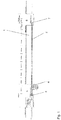
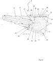
- the FIG. 1 shows in the sectional side view of the method according to the invention for removing a laid in the soil 1 plastic pipe 2.
- the plastic pipe 2 may in this case be a gas, a water or a sewage pipe, which z. B. made of PVC, PE, PET material.
- the method in this case comprises a drilling device 3 and a rotating drill pipe 4, which from a start pit 5 at the beginning to a target pit 6 at the end is inserted through the plastic pipe 2 to be removed.
- the plastic pipe 2 to be removed is first of all separated in the start pit 5 and in the target pit 6, before the drilling device 3 for the extendable drill pipe 4 in the start pit 5, which is equipped with a hydraulic aggregate, is set up in the start pit 5.
- the drill pipe 4 is then retracted or pushed with the drilling device 3 through the plastic pipe 2 to be removed into the target pit 6, as shown in the sectional view of FIG. 1 is shown.
- a tool 8 is attached to the free end 7 of the drill string 4 in the target pit 6, soft milled by rotation of the drill string 4 and retracting or retracting the drill string 4 in the direction of the starting pit 5, the plastic pipe 2 in the ground.
- a rinsing / cooling medium is pumped through the drill pipe 4 during milling or machining.
- the flushing / cooling agent exits via the tool 8 and flows back through the plastic pipe 2 to be removed with the plastic chips into the starting pit 5.
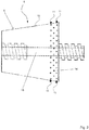
- the tool 8 as such presents itself as a truncated cone 9 or truncated cone 9, as this in the FIG. 2 and 4 is shown in more detail.
- hard metal inserts 11 are arranged, which extend over the circumference, wherein the hard metal inserts 11 can be introduced in the example shown in holes or blind holes.
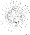
- FIG. 4 a further embodiment is shown, wherein on the truncated cone shell 10 pockets 12 are provided, in which carbide cutting plates 13 are embedded.
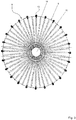
- the cutting plates 13 are in this case attached to contact surfaces in the pocket 12 and protrude radially, wherein in the FIG. 5 four cutting plates 13 are shown, which extend radially over the circumference of the truncated cone shell 10.
- Irrigation openings or channels 14 extend over the circumference of the truncated cone casing 10, as they are in the FIG. 3 but also in the FIG. 4 are shown in more detail. Also in the figure 5 Flushing channels 14 can be seen, which extend radially from the drill pipe channel 15 in the axis of rotation.
- the flushing channels 14 are radially arranged such that they always have an intermediate layer between the hard metal inserts 11, so that corresponding to each cemented carbide insert 11 flushing / cooling agent can escape.
- each cutting plate 13 is associated with a respective flushing channel 14.
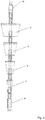
- a swivel 16 can be mounted to the free end 7 of the truncated cone cutter 9, by means of which a not-shown new pipe can be pulled from the target pit 6 from.
- a plurality of truncated cone cutters 9 can be mounted in series with each other, as also shown in FIG FIG. 6 is shown.
- the invention also relates in the same way to the device and the tool 8 for removing a laid in the soil 1 plastic pipe 2, such as a gas pipe or a water pipe, which z. B. made of PVC, PE, PET material.
- the device in this case comprises a drilling device 3 with a rotating drill pipe 4, which is arranged in a start pit 5.
- a frusto-conical tool 8 can be fixed to the free end 7 of the drill string 4 in the target pit 6, which zerfrangle by train and rotation the plastic shell of the tube 2, machined or zersc discourse.
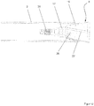
- FIGS. 7 . 8th . 9 and 10 show a further embodiment of the tool 8 according to the invention for carrying out the method.
- this has recesses 18 on the truncated cone shell 10.
- shaped segment plates 19 are fixed with a diamond coating by means of a screw 20.
- the segment plates 19 in this case extend over the lateral surface 23 of the truncated cone body 17, so that forms a correspondingly running at an angle peeling or Zerspanungs Simulationring that a stable alignment for the peeling and machining process, which adjusts itself substantially to the pipe inner wall and guide for the rotating truncated cone body 17, as indicated in the FIG. 12 is recognizable.
- the recesses 18 and the shaped segment plates 19 are arranged on the truncated cone shell 10 with diamond coating under a shaped rotation over the lateral surface of the truncated cone, as shown in FIG. 8 and 10 in the plan view becomes clear.
- the shaped rotation of the truncated cone body 17 from the front connection region to the rear end region results in a kind of quarter-thread shape, which favors the peeling and milling process, since the lateral surface 23 moves helically on the cutting surface ring in the tube 2.
- the individual recess 18 here comprises a step-like edge 24 on which the shaped segment plate 19 rests in the mounted state, as can be seen from the sectional illustrations of FIGS Figures 9 and 10 is apparent.
- the formation of the step-like support in the recess 18 results between the bottom 25 of the recess 18 and the back of the molded mounted segment plate 19, a slit-shaped flat cavity 26 which is provided for receiving the pumped into the truncated cone body 17 flushing.
- the scavenging occurs between the shaped segment plates 19 mounted on the recesses 18 at the longitudinal gap spaces 27 extending between the longitudinal sides of the assembled segment plates 19.
- Truncated cone bodies 17 are particularly in the FIG. 11 closer and better to see where in particular the truncated cone body 17 is shown without the assembled segment plates 19.
- the truncated cone body 17 is here distributed over its circumference with flushing channels 29 interspersed, which extend between a running in the axis of rotation flushing channel 30 and the recesses 18.
- the truncated cone body 17 has in the axis of rotation a threaded receptacle for an adapter piece 31 to which the drill pipe 4 is connected.
Landscapes
- Engineering & Computer Science (AREA)
- General Engineering & Computer Science (AREA)
- Environmental & Geological Engineering (AREA)
- Mechanical Engineering (AREA)
- Geology (AREA)
- Mining & Mineral Resources (AREA)
- Life Sciences & Earth Sciences (AREA)
- Fluid Mechanics (AREA)
- Physics & Mathematics (AREA)
- General Life Sciences & Earth Sciences (AREA)
- Geochemistry & Mineralogy (AREA)
- Earth Drilling (AREA)
- Perforating, Stamping-Out Or Severing By Means Other Than Cutting (AREA)
Abstract
Die Erfindung betrifft ein Verfahren zum Entfernen eines im Erdreich (1) verlegten Kunststoffrohres (2), wie ein Gas-, ein Wasser-, ein Abwasserrohr oder dergleichen, welches aus PVC, PE, PET Material besteht, mit einer Bohrvorrichtung (3) und einem rotierenden Bohrgestänge (4), wobei zunächst eine Startgrube (5) am Anfang und eine Zielgrube (6) am Ende der zu entfernenden Rohrlänge ausgehoben wird, und wobei dann das zu entfernende Kunststoffrohr (2) in der Startgrube (5) und in der Zielgrube (6) aufgetrennt wird. Erfindungsgemäß wird nach dem Verfahren die mit einem Hydraulikaggregat ausgestattete Bohrvorrichtung (3) für das verlängerbare Bohrgestänge (4) in der Startgrube (5) aufgestellt, und das Bohrgestänge (4) durch das zu entfernende Kunststoffrohr (2) bis in die Zielgrube (6) eingefahren bzw. geschoben, und wobei dann an das freie Ende (7) des Bohrgestänges (4) in der Zielgrube (6) ein Werkzeug (8) angesetzt wird, weiches unter Rotation des Bohrgestänges (4) und Einfahren bzw. Zurückziehen des Bohrgestänges (4) in Richtung zur Startgrube (5) das Kunststoffrohr (2) im Erdreich zerfräst bzw. zerspant.The invention relates to a method for removing a in the soil (1) laid plastic pipe (2), such as a gas, a water, sewage pipe or the like, which consists of PVC, PE, PET material, with a drilling device (3) and a rotating drill pipe (4), wherein first a starting pit (5) at the beginning and a target pit (6) is excavated at the end of the pipe length to be removed, and in which case to be removed plastic pipe (2) in the starting pit (5) and in the Target pit (6) is separated. According to the invention equipped with a hydraulic unit drilling device (3) for the extendable drill pipe (4) in the starting pit (5), and the drill pipe (4) through the plastic pipe to be removed (2) into the target pit (6) retracted or pushed, and then at the free end (7) of the drill string (4) in the target pit (6) a tool (8) is recognized soft with rotation of the drill string (4) and retracting or retracting the drill string ( 4) in the direction of the starting pit (5) the plastic pipe (2) zerfräst or machined in the ground.
Description
Die Erfindung betrifft ein Verfahren zum Entfernen eines im Erdreich verlegten Kunststoffrohres wie ein Gasrohr, ein Wasserrohr, ein Abwasserrohr oder dergleichen, welches z. B. aus PVC, PE, PET Material besteht, mit einer Bohrvorrichtung und einem rotierenden Bohrgestänge, wobei zunächst eine Startgrube am Anfang und eine Zielgrube am Ende der zu entfernenden Rohrlänge ausgehoben wird und wobei dann das zu entfernende Rohr in der Startgrube und in der Zielgrube aufgetrennt wird.The invention relates to a method for removing a laid in the ground plastic pipe such as a gas pipe, a water pipe, a sewer pipe or the like, which z. B. made of PVC, PE, PET material, with a boring device and a rotating drill pipe, wherein first a starting pit at the beginning and a target pit at the end of the pipe length to be removed is dug and then being removed pipe in the starting pit and in the target pit is separated.
Aufgrund der fortschreitenden technischen Entwicklung werden im Erdbereich verlegte Altrohre, die z. B. aus PVC, PE oder PET Material bestehen, wie Gas-, Wasser- oder Abwasserrohre stillgelegt, wobei insbesondere diese Rohre, wie gesagt, aus Kunststoffen bestehen. Diese Rohre, soweit sie nicht mehr benötigt werden, verbleiben dann in der Erde. Nur für den Fall, dass aufgrund von Straßenerweiterungen oder von Erneuerungen von Kanälen das darüber liegende Erdreich abgeräumt ist, werden diese Rohre mit geborgen. Ansonsten besteht nur die Möglichkeit, in einem aufwändigen Verfahren, Erde abzutragen oder Gräben auszuheben, um auf diese Weise die Rohre freizulegen, damit diese aus dem Erdreich herausgenommen werden können.Due to the progressive technical development laid in the earth area old pipes, z. B. made of PVC, PE or PET material, such as gas, water or sewage pipes shut down, in particular, these pipes, as I said, made of plastics. These pipes, if they are no longer needed, then remain in the ground. Only in the event that due to road extensions or renewal of channels, the overlying soil is cleared, these pipes with salvaged. Otherwise, it is only possible to remove soil or excavate trenches in an elaborate process in order to expose the pipes so that they can be removed from the ground.
Der Erfindung stellt sich somit das Problem, stillgelegte Kunststoffrohrleitungen, wie beispielsweise Gasrohrleitungen, Wasserleitungen oder Abwasserrohrleitungen, deren Verwendung im Erdreich nicht mehr benötigt werden oder zulässig sind, kostengünstig im Erdreich zu entfernen und einem Recyclingprozess zuzuführen, ohne dass die Erdoberfläche abgetragen werden muss, oder ein Graben ausgehoben werden muss, was bei hochwertigen Oberflächen hohe Kosten verursacht.The invention thus raises the problem of disused plastic pipelines, such as gas pipelines, water pipes or sewage pipelines, the use of which is no longer needed or permitted in the ground to remove economically in the ground and supply a recycling process without the earth's surface being removed or digging a ditch, which costs high quality surfaces.
Erfindungsgemäß wird dieses Problem mit den Merkmalen des Anspruchs 1 sowie des Anspruchs 8 gelöst. Vorteilhafte Ausgestaltungen der Erfindung ergeben sich aus den Unteransprüchen.According to the invention, this problem is solved by the features of
Bei dem erfindungsgemäßen Verfahren zum Entfernen eines im Erdreich verlegten Kunststoffrohres werden zunächst eine Startgrube und eine Zielgrube freigelegt, zwischen denen das erdverlegte Kunststoffrohr entfernt werden soll. Das zu entfernende Kunststoffrohr wird in der Startgrube und in der Zielgrube aufgetrennt. Eine Bohrvorrichtung mit Hydraulikaggregat, ersatzweise ein Horizontalbohrgerät auf Lafette für Vorschub und Rotation, wird dann auf der Grubensohle der Startgrube bzw. an der Startgrube positioniert. Gleichzeitig wird an das Bohrgerät eine Hochdruckpumpe angeschlossen, mittels der eine Flüssigkeit zur Spülung und Kühlung durch das Rohrgestänge gepumpt werden kann.In the method according to the invention for removing a plastic pipe laid in the ground, first of all a starting pit and a target pit are uncovered, between which the buried plastic pipe is to be removed. The plastic pipe to be removed is separated in the starting pit and in the target pit. A drilling device with hydraulic unit, alternatively a horizontal drilling rig on carriage for feed and rotation, is then positioned on the pit bottom of the starting pit or at the starting pit. At the same time a high-pressure pump is connected to the drill, by means of a liquid for flushing and cooling can be pumped through the pipe string.
Das Bohrgestänge wird dann zunächst von der Startgrube aus durch das zu entfernende Kunststoffrohr bis zur Zielgrube geschoben bzw. eingefahren. Sollten zwischen Start- und Zielgrube allerdings Rohrwinkel oder enge Rohrbögen liegen, müssten dann auf dem zu entfernenden Kunststoffrohrabschnitt an diesen Stellen Zwischengruben d. h. Start-/Zielgruben erstellt werden. In der Zielgrube, in die dann das freie Ende des Bohrgestänges ragt, wird das Werkzeug umfassend einen Kegelstumpffräser oder Kegelstumpfschäler auf das freie Gestänge montiert.The drill pipe is then pushed or retracted from the starting pit through the plastic pipe to be removed to the target pit. If, however, pipe angles or narrow pipe bends are located between the start and target pit, intermediate pits d would have to be formed on the plastic pipe section to be removed at these points. H. Start / Zielgruben be created. In the target pit, in which then projects the free end of the drill string, the tool is mounted on the free linkage comprising a truncated cone or truncated cone peeler.
Wenn das Kunststoffrohr nur entfernt werden soll, wird an den Kegelstumpf eine Verschlusskappe aufgeschraubt, die den Bohrgestängekanal rückwärtig verschließt. Soll beispielsweise eine Auswechselung des abgängigen Kunststoffrohres erfolgen, kann auf den Gewindestumpf des Kegelstumpfes ein Drallfänger angeschraubt werden. Wenn nun ein Drallfänger montiert ist, kann hier mit einer entsprechenden Vorrichtung ein neues Rohr oder auch eine Leitung befestigt werden, um dann mit fortschreitendem Einzug des Kegelstumpffräsers oder Kegelstumpfschälers in Richtung Startgrube eingezogen zu werden. Das neue Rohr würde auf diese Weise ohne irgendeine Verschmutzung im Inneren des Rohres eingezogen. Es entstehen keine zusätzlichen Kosten für die Reinigung.If the plastic pipe is only to be removed, a cap is screwed to the truncated cone, which closes the Bohrgestängekanal backward. If, for example, a replacement of the discontinuous plastic pipe takes place, the threaded stump of the truncated cone can be inserted Swivel catch to be screwed on. Now, if a swivel is mounted, a new pipe or a line can be attached here with a corresponding device, to then be drawn with progressing entry of the truncated cone or truncated cone peeler in the direction of starting pit. The new tube would be drawn in this way without any contamination inside the tube. There are no additional costs for cleaning.
Das Bohrgestänge wird dann unter Rotation und hydraulischem Zug Richtung Startgrube zurückgezogen. Durch die Rotation und der Zugkraft des Hydraulikaggregates oder Horizontalbohrgerätes wird das im Erdreich befindliche Kunststoffrohr zerfräst, zerspant bzw. zerschält. In Folge eines unter hohem Druck eingepumpten Spül-/Kühlmittels wird das zerfräste, zerspante oder zerschälte Kunststoffmaterial durch die noch vorhandene Rohrlänge zur Startgrube ausgespült und ausgetragen. Das zurückströmende Spül-/Kühlmittel mit den Kunststoffteilchen wird in der Startgrube mittels einer Vakuumpumpe abgesaugt. Das abgesaugte Spül-/Kühlmittel mit den darin befindlichen Kunststoffteilchen wird über eine Recyclingtrennungsanlage geführt, um das Kunststoffmaterial zu extrahieren, um es einer Wiederverwertung zuzuführen. Die Anwendung dieses Verfahrens ist sowohl in Bereichen mit einfachen sowie hauptsächlich auch mit hochwertigen Geländeoberflächen von besonderem Vorteil, wenn z. B. bei der Auswechselung von Gas- und Wasserleitungen diese im städtischen Bereich mit etlichen Hausanschlüssen versehen sind. Dann können diese Abzweigpunkte für die Hausanschlüsse gleichzeitig als Start- und Zielgruben genutzt werden.The drill string is then withdrawn under rotation and hydraulic train towards the starting pit. Due to the rotation and the tensile force of the hydraulic unit or horizontal drilling machine, the plastic pipe located in the ground is milled, machined or shredded. As a result of a flushing / cooling agent pumped in under high pressure, the milled, chipped or crushed plastic material is rinsed out through the remaining pipe length to the starting pit and discharged. The backflowing rinse / coolant with the plastic particles is sucked in the starting pit by means of a vacuum pump. The extracted rinse / coolant with the plastic particles therein is passed through a recycling separation plant to extract the plastic material for recycling. The application of this method is in both areas with simple and mainly with high-quality terrain surfaces of particular advantage when z. B. in the replacement of gas and water pipes they are provided in the urban area with several house connections. Then these branch points for the house connections can be used simultaneously as start and destination pits.
Das Verfahren zeichnet sich dadurch aus, dass keine neuen Trassen erforderlich sind und eine Minimierung des Öffnens von Geländeoberflächen erzielt wird. Das zerfräste, zerspante oder zerschälte Kunststoffmaterial kann entsprechend entsorgt und dem Wirtschaftskreislauf zugeführt werden.The method is characterized by the fact that no new routes are required and a minimization of the opening of terrain surfaces is achieved. The milled, machined or crushed plastic material can be disposed of appropriately and fed to the economic cycle.
In besonders vorteilhafter Ausgestaltung des Werkzeuges besteht dieses aus einem Kegelstumpffräser oder Kegelstumpfschäler, der als konischer Zylinderkegel ausgebildet ist. Der Kegelstumpf ist an seiner vorderen Zugseite, die den kleineren Durchmesser aufweist, mit einem Innengewinde versehen, in welches das freie Ende des Bohrgestänges eingeschraubt wird. Auf der rückwärtigen Seite des Kegelstumpfes ist ein durchschlägiger Gewindestutzen vorhanden, auf den eine Verschlusskappe oder ein Drallfänger aufgeschraubt werden kann. Durch die zylindrische Form des Kegelstumpfes wird durch den Zug der Hydraulik eine gute Führung und auch eine gewisse Abdichtung im bzw. am Ende des zu entfernenden Kunststoffrohres gewährleistet.In a particularly advantageous embodiment of the tool, this consists of a truncated cone or truncated cone peeler, which is designed as a conical cylindrical cone. The truncated cone is provided on its front tension side, which has the smaller diameter, with an internal thread into which the free end of the drill string is screwed. On the rear side of the truncated cone a durchschlägiger threaded neck exists on which a cap or a swivel can be screwed. Due to the cylindrical shape of the truncated cone is ensured by the train of hydraulic good guidance and also a certain seal in or at the end of the plastic pipe to be removed.
Nach einer ersten Variante des Kegelstumpffräsers ist der Kegelstumpfkörper mit radial angeordneten Bohrungen zu dem in der Rotationsachse liegenden durchgängigen Kanal versehen. In den Bohrungen sind Gewinde eingeschnitten, in die entsprechend den örtlichen Anforderungen, d. h. Material und Bodenverhältnisse, die erforderlichen Zubehörteile eingeschraubt werden. Diese Zubehörteile sind Verschlussschrauben, Einschraubdüsen und Hartmetallfräser. Diese Hartmetallfräser auf dem Kegelfräser dienen dazu, das Kunststoffrohr durch die Rotation und die Zugkraft des Hydraulikaggregates zu zerfräsen bzw. zu zerspanen. Durch die Einschraubdüsen wird das erforderliche Spül-/ Kühlmittel gedrückt.According to a first variant of the truncated cone cutter, the truncated cone body is provided with radially arranged bores to the continuous passage located in the axis of rotation. Threads are cut in the holes in accordance with local requirements, d. H. Material and soil conditions, the necessary accessories are screwed. These accessories are screw plugs, screw-in nozzles and carbide cutters. These carbide cutters on the bevel cutter serve to mill or machine the plastic pipe by the rotation and the tensile force of the hydraulic unit. The screw-in nozzles push the required flushing / cooling agent.
Nach einer weiteren Variante des Kegelstumpffräsers als Kegelstumpfschäler werden an dem zuvor beschriebenen Kegelstumpfkörper Taschen mit Anlageflächen am Kegelstumpfkörper ausgefräst oder eingeformt. In bzw. an den Anlageflächen der Taschen werden Sackgewinde eingeschnitten, um dort Hartmetalischneidplatten anzuschrauben. Mit der Rotation und der Zugkraft durch das Hydraulikaggregat wird mit den Hartmetallschneidplatten das Kunststoffrohr zerspant bzw. zerschält. Auch ist der Kegelstumpfkörper in bestimmten Bereichen mit radial angeordneten Bohrungen zu dem in der Rotationsachse liegenden durchgängigen Kanal versehen. In den Bohrungen sind Gewinde eingeschnitten, in die entsprechend den örtlichen Anforderungen, d. h. Material und Bodenverhältnisse, die erforderlichen Zubehörteile eingeschraubt werden. Diese Zubehörteile sind Verschlussschrauben und Einschraubdüsen. Durch die Einschraubdüsen wird dann das erforderliche Spül-/Kühlmittel gedrückt.According to a further variant of the truncated cone cutter as a truncated cone peeler, pockets with contact surfaces on the truncated cone body are milled or formed on the truncated cone body described above. In or on the contact surfaces of the bags sack thread are cut to screw hardmetalischneidplatten there. With the rotation and the tensile force through the hydraulic unit, the plastic pipe is machined or shattered with the carbide cutting plates. Also, the truncated cone body is provided in certain areas with radially arranged bores to the lying in the axis of rotation through channel. In the holes are threaded incisions, in accordance with local requirements, ie material and soil conditions, the necessary accessories are screwed in. These accessories are screw plugs and screw-in nozzles. The screw-in nozzles then push the required flushing / cooling agent.
Der Kegelstumpffräser oder Kegelstumpfschäler wird über ein Hydraulikaggregat oder ein Horizontalbohrgerät angetrieben. Zur Kühlung beim Zerfräsen, Zerspanen oder Zerschälen wird durch die Hochdruckpumpe ein zulässiges Spül-/Kühlmittel über das Bohrgestänge und die Einschraubdüsen in den Arbeitsbereich gedrückt. Gleichzeitig dient dieses Spül-/Kühlmittel dazu, die Fräs-, Span- oder Schälteilchen über das noch vorhandene Restrohr längs des Bohrgestänges Richtung Hydraulikaggregat bzw. Startgrube auszuspülen bzw. auszutragen. Im Bereich des Hydraulikaggregates, d. h. in der Startgrube, wird das Spül-/Kühlmittel mit den darin befindlichen Kunststoffteilchen mittels einer Vakuumpumpe abgesaugt. In einem Recyclingtrennungsverfahren werden dann die Kunststoffteilchen von dem Spül-/Kühlmittel separiert, entsprechend entsorgt und der Weiterverarbeitung bzw. dem Wirtschaftskreislauf zugeführt.The truncated cone or truncated cone peeler is driven by a hydraulic aggregate or a horizontal boring machine. For cooling during milling, chipping or slicing, a permissible flushing / cooling agent is forced into the working area via the drill pipe and the screw-in nozzles. At the same time, this flushing / cooling agent serves to rinse or discharge the milling, chip or peeling particles along the remaining pipe along the drill string in the direction of the hydraulic unit or starting pit. In the area of the hydraulic unit, d. H. in the starting pit, the rinsing / cooling agent is sucked with the plastic particles contained therein by means of a vacuum pump. In a recycling separation process, the plastic particles are then separated from the flushing / cooling agent, disposed of appropriately and fed to further processing or to the economic cycle.
An der rückwärtigen Stirnflächenseite des Kegelstumpfkörpers kann auf den durchschlägigen Gewindestutzen eine Verschlusskappe oder ein Drallfänger aufgeschraubt werden, damit dort kein Spül-/Kühlmittel austreten kann. Über einen Drallfänger, der mit einem Innengewinde, passend zum Gewindestutzen des Kegelstumpffräsers oder Kegelstumpfschälers versehen ist, kann ein neues Rohr oder eine neue Leitung befestigt werden. Sollte es gewünscht sein für das vorhandene zu erneuernde Rohr ein Rohr mit größerem Durchmesser einzuziehen, kann zwischen dem Kegelstumpffräser oder Kegelstumpfschäler und dem Drallfänger noch ein Aufweitekopf montiert werden.On the rear end face side of the truncated cone body, a closure cap or a swivel catch can be screwed onto the piercing threaded neck so that no flushing / cooling agent can escape there. Via a swivel, which is provided with an internal thread, matching the threaded neck of the truncated cone or truncated cone peeler, a new pipe or a new line can be attached. Should it be desired to feed in a larger diameter pipe for the existing pipe to be renewed, an expanding head can still be installed between the truncated cone cutter or truncated cone peeler and the swivel catcher.
Bei der erfindungsmäßigen Vorrichtung ergeben sich somit folgende Vorteile, die darin zu sehen sind, dass eine komplette Entfernung des vorhandenen Kunststoffrohres aus dem Erdreich und Rückführung in den Wirtschaftskreislauf erfolgen kann. Es müssen keine neuen Trassen, angesichts der wenigen Ressourcen, gerade in innerstädtischen Bereichen, erstellt oder gesucht werden. Daraus ergibt sich eine absolute Kostenoptimierung durch die Minimierung des Öffnens von vor allem hochwertigen Oberflächen.In the apparatus according to the invention, there are thus the following advantages, which can be seen in the fact that a complete removal of the existing plastic pipe from the ground and return to the economic cycle can be done. There is no need to create or search new routes, given the limited resources available, especially in inner-city areas. This results in an absolute cost optimization by minimizing the opening of especially high-quality surfaces.
Gemäß der Erfindung wird hierzu merkmalsgemäß vorgeschlagen, dass die mit einem Hydraulikaggregat ausgestatte Bohrvorrichtung für das verlängerbare Rohrgestänge in der Startgrube aufgestellt wird, ersatzweise könnte auch ein Horizontalbohrgerät auf Lafette im Startgrubenbereich aufgestellt werden. Das Rohrgestänge wird durch das zu entfernende Kunststoffrohr bis in die Zielgrube eingefahren bzw. eingeschoben. In der Zielgrube wird an das freie Ende des Rohrgestänges ein Werkzeug montiert, welches unter Rotation des Rohrgestänges und Einfahren bzw. Zurückziehen des Rohrgestänges in Richtung zur Startgrube das Rohr im Erdreich zerfräst, zerspant oder zerschält.According to the invention, it is proposed according to feature that the equipped with a hydraulic unit boring device for the extendable pipe string is placed in the starting pit, alternatively, a horizontal boring machine could be placed on carriage in the starting pit area. The pipe string is retracted or inserted through the plastic pipe to be removed into the target pit. In the target pit, a tool is mounted on the free end of the pipe string, which mills the pipe in the ground under rotation of the pipe string and retracting or retracting the pipe boom in the direction of the starting pit, machined or zerschält.
In vorteilhafter Ausgestaltung wird hiermit beim Zerfräsen, Zerspanen oder Zerschälen durch das Rohrgestänge Spül-/Kühlmittel gepumpt. Das Spül-/Kühlmittel tritt hierbei über das Werkzeug aus und wird durch das vorhandene Kunststoffrohr mit den Kunststoffteilchen längs des Bohrgestänges zur Startgrube zurückgeleitet. Nach einer besonders vorteilhaften Ausgestaltung der Erfindung wird als Werkzeug ein Kegelstumpf verwendet, an dessen Kegelstumpfmantel Hartmetalleinlagen angeordnet sind. Nach einer anderen Ausführungsform der Erfindung können auch an dem Kegelstumpfmantel Taschen mit Anlageflächen vorhanden sein, in denen Hartmetallschneidplatten radial liegend oder stehend angeordnet sind.In an advantageous embodiment, hereby rinsing / cooling medium is pumped through the pipe string during milling, chipping or slicing. The flushing / cooling agent exits via the tool and is returned to the starting pit through the existing plastic pipe with the plastic particles along the drill string. According to a particularly advantageous embodiment of the invention, a truncated cone is used as a tool, are arranged on the truncated cone coat carbide inserts. According to another embodiment of the invention may be present on the truncated cone jacket pockets with contact surfaces in which carbide cutting plates are arranged radially lying or standing.
In der Weiterbildung ist der Kegelstumpf über seinen Umfang verteilt mit Gewindeöffnungen zur Aufnahme von Spüldüsen durchsetzt, durch die beim Zerfräsungs-, Zerspanungs- oder Zerschälungsvorgang das Spül-/Kühlmittel austritt. Nach einer besonders vorteilhaften Ausgestaltung kann auf das freie Ende des Kegelstumpfes auf den Gewindestumpf eine Verschlusskappe oder ein Drallfänger montiert werden. Mittels des Drallfängers kann ein neues Rohr oder eine neue Leitung von der Zielgrube her eingezogen werden.In the development of the truncated cone is distributed over its circumference with threaded openings for receiving rinsing nozzles penetrated through the flushing, cutting or Zerschälungsvorgang the flushing / coolant exits. According to a particularly advantageous embodiment can on the free end of the truncated cone on the threaded stub a cap or a swivel can be mounted. By means of the swivel catcher, a new pipe or a new pipe can be pulled in from the target pit.
Die Erfindung betrifft in gleicher Weise auch eine Vorrichtung zum Entfernen eines im Erdreich verlegten Kunststoffrohres, wie beispielsweise ein Gas-, Wasser-, Abwasserrohr oder dergleichen, welches z. B. aus PVC, PE, PET Material besteht, umfassend eine Bohrvorrichtung mit einem rotierenden Bohrgestänge, welches in einer Startgrube angeordnet ist, ersatzweise wäre auch ein Horizontalbohrgerät auf Lafette möglich. Die Vorrichtung zeichnet sich hierbei dadurch aus, dass an das freie Ende des Bohrgestänges in einer Zielgrube ein kegelstumpfartiges Werkzeug festlegbar ist, welches durch Rotation und Zug den Kunststoffmantel des Rohres zerfräst, zerspant oder zerschält. Der Kegelstumpf weist hierbei an seinem Kegelstumpfmantel Hartmetalleinlagen auf. Nach einer weiteren Ausgestaltung sind an dem Kegelstumpfkörper Taschen mit Anlageflächen vorgesehen, in denen Hartmetallschneidplatten befestigt sind. Die Hartmetallschneidplatten stehen hier radial ab, sodass sich diese aufgrund der Konizität in das Rohrmaterial einschneiden und dieses zerschälen. Wie bereits beschrieben, ist der Kegelstumpf über seinen Umfang verteilt mit Gewindeöffnungen zum Einschrauben von Spüldüsen durchsetzt. An das freie Ende des Kegelstumpfes kann eine Verschlusskappe oder ein Drallfänger montiert werden. Über den Drallfänger kann eine neue Leitung von der Zielgrube her eingezogen werden.The invention also relates in the same way to a device for removing a plastic pipe laid in the ground, such as a gas, water, sewage pipe or the like, which z. B. from PVC, PE, PET material, comprising a drilling device with a rotating drill pipe, which is arranged in a starting pit, alternatively, a horizontal drilling rig on carriage would be possible. The device is characterized by the fact that at the free end of the drill string in a target pit a truncated cone-like tool can be fixed, which mills by rotation and train the plastic jacket of the pipe, machined or zerschält. The truncated cone has in this case on its truncated cone hard metal deposits. According to a further embodiment, pockets with contact surfaces are provided on the truncated cone body, in which carbide cutting plates are attached. The carbide cutting plates protrude radially so that they cut into the tube material due to the conicity and shell it. As already described, the truncated cone is distributed over its circumference with threaded openings for screwing in flushing nozzles. At the free end of the truncated cone, a cap or a swivel can be mounted. A new pipe can be pulled in from the target pit via the swivel catcher.
Es besteht auch die Möglichkeit bei dem System, dass mehrere Kegelstümpfe in Serie aneinander montiert werden können, um eine deutliche Erhöhung der Durchströmung des Spül-/Kühlmittels zu erreichen, hiermit werden die Kunststoffteilchen schneller und besser transportiert und ausgetragen.There is also the possibility in the system that multiple truncated cones can be mounted in series with each other to achieve a significant increase in the flow of the rinsing / cooling agent, hereby the plastic particles are faster and better transported and discharged.
Die Erfindung betrifft ebenfalls das Werkzeug zum Entfernen eines im Erdreich verlegten Kunststoffrohres, wie beispielsweise ein Gas-, ein Wasser- oder Abwasserrohr, welches z. B. aus PVC, PE, PET Material besteht, welches mit einer Bohrvorrichtung mit einem rotierenden Bohrgestänge zusammenwirkt, das in einer Startgrube angeordnet ist. Das Werkzeug umfasst einen Kegelstumpf, der an das freie Ende des Bohrgestänges in einer Zielgrube montiert wird, wobei der Kegelstumpf durch Zug und Rotation des Bohrgestänges den Kunststoffmantel des Rohres zerfräst, zerspant bzw. zerschält wird. Hierzu weist der Kegelstumpf an seinem Kegelstumpfmantel Hartmetalleinlagen auf. In dem Kegelstumpfmantel können auch Taschen mit Schneidplatten angeordnet sein. Über den Umfang des Kegelstumpfkörpers sind Spülungsöffnungen bzw. Kanäle vorgesehen, die mit dem Bohrgestängekanal in der Rotationsachse in Verbindung stehen.The invention also relates to the tool for removing a laid in the ground plastic pipe, such as a gas, a water or sewage pipe, which z. B. of PVC, PE, PET material, which cooperates with a drilling device with a rotating drill pipe, which is arranged in a starting pit. The tool comprises a truncated cone, which is mounted on the free end of the drill pipe in a target pit, the truncated cone by train and rotation of the drill string, the plastic shell of the tube is milled, machined or zerschält wird. For this purpose, the truncated cone on its truncated cone on hard metal inserts. Bags with inserts can also be arranged in the truncated cone casing. Irrigating openings or channels are provided over the circumference of the truncated cone body, which are in communication with the drill pipe channel in the axis of rotation.
Nach einer besonders vorteilhaften Ausgestaltung des Kegelstumpfkörpers verfügt dieser über Ausnehmungen am Kegelstumpfmantel, in denen geformte Segmentplatten mit einer Diamantbeschichtung mittels einer Verschraubung festlegbar sind. Die Segmentplatten erstrecken sich hierbei über die Mantelfläche des Kegelstumpfkörpers, so dass sich für den Schäl- und Zerspanungsvorgang, der sich im Wesentlichen an der Rohrinnenwand einstellt, ein entsprechend unter einem Winkel verlaufenden Schäl- bzw. Zerspanungsflächenring bildet, der eine stabile Ausrichtung und Führung für den rotierenden Kegelstumpfkörper bereitstellt.According to a particularly advantageous embodiment of the truncated cone body this has recesses on the truncated cone shell, in which molded segment plates can be fixed with a diamond coating by means of a screw. In this case, the segment plates extend over the lateral surface of the truncated cone body, so that a peeling or cutting surface ring running correspondingly at an angle, which forms a stable alignment and guidance for the peeling and machining process, which essentially adjusts itself to the pipe inner wall provides the rotating truncated cone body.
Hierbei sind am Kegelstumpfmantel die Ausnehmungen sowie die geformten Segmentplatten mit Diamantbeschichtung unter einer geformten Verdrehung über die Mantelfläche des Kegelstumpfes angeordnet. Durch die geformte Verdrehung des Kegelstumpfkörpers vom vorderen Anschlussbereich zum hinteren Endbereich ergibt sich eine Art Viertel-Gewinde-Form, welche den Schäl- und Fräsvorgang begünstigt, da die Mantelfläche sich schraubenartig am Zerspanungsflächenring im Rohr bewegt.Here, the recesses and the shaped segment plates are arranged with diamond coating under a shaped rotation over the lateral surface of the truncated cone on the truncated cone shell. The shaped rotation of the truncated cone body from the front connection region to the rear end region results in a kind of quarter-thread shape, which favors the peeling and milling process, since the lateral surface moves helically on the cutting surface ring in the tube.
In Weiterbildung umfasst die einzelne Ausnehmung einen stufenartigen Rand, auf dem die geformte Segmentplatte im montierten Zustand aufliegt.
Durch die Ausbildung einer stufenartigen Auflage in der Ausnehmung ergibt sich zwischen dem Boden der Ausnehmung und der Rückseite der geformten montierten Segmentplatte ein spaltförmiger flacher Hohlraum, der zur Aufnahme für die in den Kegelstumpfkörper gepumpte Spülung vorgesehen ist. Die Spülung tritt zwischen den an den Ausnehmungen montierten geformten Segmentplatten an den längsverlaufenden Spalten aus, die zwischen den Längsseiten der montierten Segmentplatten verlaufen. Für den Zufluss der Spülflüssigkeit in die Spalträume der längsverlaufenden Spalte sind am Kegelstupfkorpus eingeformte Spülschlitze im Kegelstumpfkorpus vorgesehen, die die Verbindung mit den Hohlräumen herstellen. Der Kegelstumpfkorpus ist hierbei über seinen Umfang verteilt mit Spülungskanälen durchsetzt, die sich zwischen einem in der Rotationachse verlaufenden Spülkanal und den Ausnehmungen erstrecken. Der Kegelstumpf weist in der Rotationsachse eine Gewindeaufnahme für ein Adapterstück auf, an dem das Bohrgestänge angeschlossen wird. Somit ergibt sich, dass die Spülflüssigkeit vom Bohrgestänge über den Adapter in die Spülkanäle und dann in die Hohlräume gelangt, von wo sie dann über die eingeformten Spülschlitze in die Spalten gelangt, damit sich die Spülflüssigkeit auf der Mantelfläche verteilt, von wo sie mit dem anfallenden Span in das Rohr zurückströmt.In a further development, the individual recess comprises a step-like edge on which the shaped segment plate rests in the mounted state.
By forming a step-like support in the recess results between the bottom of the recess and the back of the molded mounted segment plate a slit-shaped flat cavity which is provided for receiving the pumped into the truncated cone flushing. The flushing occurs between the shaped segment plates mounted on the recesses at the longitudinal gaps extending between the longitudinal sides of the assembled segment plates. For the inflow of the rinsing liquid into the gaps of the longitudinal column molded scavenging slots in the truncated cone body are provided on Kegelstupfkorpus, which establish the connection with the cavities. The truncated cone body is in this case distributed over its circumference interspersed with flushing channels, which extend between a running in the axis of rotation flushing channel and the recesses. The truncated cone has in the axis of rotation a threaded receptacle for an adapter piece to which the drill string is connected. Thus, it follows that the rinsing fluid from the drill string passes through the adapter into the rinsing channels and then into the cavities, from where it then passes through the molded scavenging slots in the columns, so that the rinsing liquid distributed on the lateral surface, from where it with the accruing Span flows back into the pipe.
An das freie Ende des Kegelstumpfes ist ein Drallfänger montierbar, mittels dem ein neues Rohr von der Zielgrube her eingezogen werden kann.At the free end of the truncated cone a swivel catch can be mounted, by means of which a new pipe can be pulled in from the target pit.
Ein Ausführungsbeispiel der Erfindung ist in den Zeichnungen rein schematisch dargestellt und wird nachfolgend näher beschrieben. Es zeigt
Figur 1- eine Seitenansicht des erfindungsgemäßen Verfahrens;
Figur 2- eine Seitenansicht eines Kegelstumpffräsers gemäß einer ersten Ausführungsform;
Figur 3- eine geschnittene Stirnansicht des Kegelstumpffräsers gemäß der
Figur 2 Figur 4- eine weitere Seitenansicht eines kegelstumpfartigen Werkzeugs gemäß einer weiteren Ausführungsform;
Figur 5- eine Stirnansicht des kegelstumpfartigen Werkzeuges gemäß der
Figur 4 Figur 6- eine Darstellung von mehreren Werkzeugen in der Serienanordnung mit einem endseitig angeordneten Drallfänger;
Figur 7- eine seitliche Darstellung einer weiteren Ausführungsform eines Werkzeugs gemäß der Erfindung,
Figur 8- eine Draufsicht auf das Werkzeug gemäß der
Figur 7 Figur 9- eine geschnittene Seitenansicht gemäß der Schnittlinie A - A in
der Figur 8 ; Figur 10- eine geschnittene Draufsicht gemäß der Schnittlinie B - B in
der Figur 7 ; Figur 11- eine Seitenansicht des Kegelstupfkörpers ohne Segmentplatten und
Figur 12- eine weitere Seitenansicht des erfindungsgemäßen Werkzeugs in einem Rohr.
- FIG. 1
- a side view of the method according to the invention;
- FIG. 2
- a side view of a truncated cutter according to a first embodiment;
- FIG. 3
- a sectional front view of the truncated cutter according to the
FIG. 2 , with radially arranged flushing channels; - FIG. 4
- a further side view of a truncated cone-like tool according to another embodiment;
- FIG. 5
- an end view of the truncated-cone-like tool according to the
FIG. 4 , with integrated inserts; - FIG. 6
- a representation of several tools in the series arrangement with an end mounted swivel;
- FIG. 7
- a side view of another embodiment of a tool according to the invention,
- FIG. 8
- a plan view of the tool according to the
FIG. 7 - FIG. 9
- a sectional side view along the section line A - A in the
FIG. 8 ; - FIG. 10
- a sectional plan view along the section line B - B in the
FIG. 7 ; - FIG. 11
- a side view of the Kegelstupfkörpers without segment plates and
- FIG. 12
- another side view of the tool according to the invention in a tube.
Die
Dann wird an das freie Ende 7 des Bohrgestänges 4 in der Zielgrube 6 ein Werkzeug 8 angesetzt, weiches unter Rotation des Bohrgestänges 4 und Einfahren bzw. Zurückziehen des Bohrgestänges 4 in Richtung zur Startgrube 5 das Kunststoffrohr 2 im Erdreich zerfräst bzw. zerspant. Hierbei wird beim Zerfräsen oder Zerspanen durch das Bohrgestänge 4 ein Spül-/Kühlmittel gepumpt. Das Spül-/Kühlmittel tritt hierbei über das Werkzeug 8 aus und fließt durch das zu entfernende Kunststoffrohr 2 mit den Kunststoffspänen in die Startgrube 5 zurück.Then, a
Das Werkzeug 8 als solches stellt sich hierbei als Kegelstumpffräser 9 oder Kegelstumpfschäler 9 dar, wie dieser in der
Gemäß der Ausführungsform der
Wie insbesondere aus der
Die Erfindung betrifft in gleicher Weise auch die Vorrichtung und das Werkzeug 8 zum Entfernen eines im Erdreich 1 verlegten Kunststoffrohres 2, wie beispielsweise ein Gasrohr oder ein Wasserrohr, welches z. B. aus PVC, PE, PET Material besteht. Die Vorrichtung umfasst hierbei eine Bohrvorrichtung 3 mit einem rotierenden Bohrgestänge 4, welches in einer Startgrube 5 angeordnet ist. Wie insbesondere aus der
Die
Hierbei sind am Kegelstumpfmantel 10 die Ausnehmungen 18 sowie die geformten Segmentplatten 19 mit Diamantbeschichtung unter einer geformten Verdrehung über die Mantelfläche des Kegelstumpfes angeordnet, wie dies aus der
In Weiterbildung umfasst hierbei die einzelne Ausnehmung 18 einen stufenartigen Rand 24, auf dem die geformte Segmentplatte 19 im montierten Zustand aufliegt, wie dies aus den geschnittenen Darstellungen der
Der Kegelstumpfkorpus 17 ist hierbei über seinen Umfang verteilt mit Spülungskanälen 29 durchsetzt, die sich zwischen einem in der Rotationachse verlaufenden Spülkanal 30 und den Ausnehmungen 18 erstrecken. Der Kegelstumpfkörper 17 weist in der Rotationsachse eine Gewindeaufnahme für ein Adapterstück 31 auf, an dem das Bohrgestänge 4 angeschlossen wird. Somit ergibt sich, dass die Spülflüssigkeit vom Bohrgestänge 4 über den Adapter 31 in die Spülkanäle 29 und dann in die Hohlräume 26 gelangt, von wo sie dann über die eingeformten Spülschlitze 28 in die Spalträume 27 gelangt, damit sich die Spülflüssigkeit auf der Mantelfläche 23 verteilt, von wo sie mit dem anfallenden Span in das verbleibende Rohr 2 erkennbar in der
- 0101
- Erdreichsoil
- 0202
- KunststoffrohrPlastic pipe
- 0303
- Bohrvorrichtungdrilling
- 0404
- Bohrgestängedrill pipe
- 0505
- Startgrubestarting pit
- 0606
- Zielgrubetarget pit
- 0707
- Freies Ende BohrgestängeFree end drill pipe
- 0808
- WerkzeugTool
- 0909
- KegelstumpffräserBevel cutter
- 1010
- KegelstumpfmantelTruncated cone
- 1111
- HartmetalleinlageTungsten carbide inserts
- 1212
- TaschenBags
- 1313
- Schneidplattencutting boards
- 1414
- Kanälechannels
- 1515
- BohrgestängekanalBohrgestängekanal
- 1616
- DrallfängerSwivels
- 1717
- KegelstumpfkörperTruncated cone body
- 1818
- Ausnehmungenrecesses
- 1919
- Segmentplattensegment plates
- 2020
- Verschraubungscrew
- 2121
- Vorderer AnschlussbereichFront connection area
- 2222
- Hinterer EndbereichRear end area
- 2323
- Mantelflächelateral surface
- 2424
- Stufenartiger RandStepped edge
- 2525
- Boden AusnehmungBottom recess
- 2626
- Hohlraumcavity
- 2727
- Spalträumegaps
- 2828
- Spülschlitzescavenging
- 2929
- Spülkanäleflushing channels
- 3030
- Spülkanal RotationsachseFlushing channel rotation axis
- 3131
- Adapterstückadapter piece
Claims (19)
gekennzeichnet dadurch,
dass die mit einem Hydraulikaggregat ausgestattete Bohrvorrichtung (3) für das verlängerbare Bohrgestänge (4) in und im Bereich der Startgrube (5) aufgestellt wird, und das Bohrgestänge (4) durch das zu entfernende Kunststoffrohr (2) bis in die Zielgrube (6) eingefahren bzw. geschoben wird, und wobei dann an das freie Ende (7) des Bohrgestänges (4) in der Zielgrube (6) ein Werkzeug (8) angesetzt wird, welches unter Rotation des Bohrgestänges (4) und Einfahren bzw. Zurückziehen des Bohrgestänges (4) in Richtung zur Startgrube (5) das Kunststoffrohr (2) im Erdreich zerfräst, zerspant oder zerschält.Method for removing a plastic pipe (2) laid in the ground (1), such as a gas, a water, a sewage pipe or the like, which is e.g. B. from PVC, PE, PET material, with a drilling device (3) and a rotating drill pipe (4), wherein first a starting pit (5) at the beginning and a target pit (6) is excavated at the end of the pipe length to be removed, and in which case the plastic pipe (2) to be removed is separated in the starting pit (5) and in the target pit (6),
characterized by
that the drill device (3) equipped with a hydraulic aggregate for the extendable drill pipe (4) is placed in and around the start pit (5), and the drill pipe (4) through the plastic pipe (2) to be removed into the target pit (6) is retracted or pushed, and then at the free end (7) of the drill string (4) in the target pit (6) a tool (8) is recognized, which under rotation of the drill string (4) and retracting or retracting the drill string (4) in the direction of the starting pit (5) the plastic pipe (2) milled in the soil, machined or zerschält.
dadurch gekennzeichnet,
dass beim Zerfräsen, Zerspanen oder Zerschälen durch das Bohrgestänge (4) eine Spül-/Kühlmittel gepumpt wird.Method according to claim 1,
characterized,
that a rinsing / cooling medium is pumped through the drill string (4) during milling, cutting or shearing.
dadurch gekennzeichnet,
dass die Spül-/Kühlmittel über das Werkzeug (8) austritt und durch das zu entfernende Kunststoffrohr (2) mit den Kunststoffspänen, -teilchen in die Startgrube (5) zurückfließt.Method according to claims 1 and 2,
characterized,
that the rinsing / cooling agent exits via the tool (8) and flows back through the plastic pipe (2) to be removed with the plastic chips, particles into the starting pit (5).
dadurch gekennzeichnet,
dass als Werkzeug (8) ein Kegelstumpffräser (9) verwendet wird, an dessen Kegelstumpfmantel (10) Hartmetalleinlagen (11) angeordnet sind.Process according to claims 1 to 3,
characterized,
that a bevel cutter (9) is used as a tool (8), at the truncated cone (10) Cemented carbide inserts (11) are arranged.
dadurch gekennzeichnet,
dass an dem Kegelstumpfmantel (10) in Taschen (12) liegende Schneidplatten (13) oder geformte Segmentplatten mit einer Diamantbeschichtung angeordnet sind.Process according to claims 1 to 4,
characterized,
in that cutting inserts (13) located in pockets (12) or shaped segment plates with a diamond coating are arranged on the truncated cone casing (10).
dadurch gekennzeichnet,
dass der Kegelstumpfkörper über seinen Umfang verteilt mit Spülungsöffnungen bzw. Kanälen (14) durchsetzt ist.Process according to claims 1 to 5,
characterized,
that the truncated cone body is distributed over its circumference with flush openings or channels (14) interspersed.
dadurch gekennzeichnet,
dass an das freie Ende (7) des Kegelstumpffräsers (9) ein Drallfänger (16) montierbar ist, mittels dem ein neues Rohr von der Zielgrube (6) her eingezogen wird.Method according to claims 1 to 6,
characterized,
in that a swivel catcher (16) can be mounted on the free end (7) of the truncated cone cutter (9) by means of which a new tube is drawn in from the target pit (6).
dadurch gekennzeichnet,
dass das Werkzeug (8) einen Kegelstumpf umfasst, der an das freie Ende (7) des Bohrgestänges (4) in einer Zielgrube (6) festlegbar ist, wobei der Kegelstumpf durch Zug und Rotation des Bohrgestänges (4) den Kunststoffmantel des Rohres (2) zerfräst, zerspant bzw. zerschält.Tool for carrying out the method for removing a in the soil (1) laid plastic pipe (2), such as a gas, a water or sewage pipe, which z. B. of PVC, PE, PET material which cooperates with a drilling device (3) with a rotating drill pipe (4) which is arranged in a start pit (5),
characterized,
that the tool (8) comprises a truncated cone at the free end (7) of the drill string (4) in a target pit (6) can be fixed, wherein the truncated cone by train and rotation of the drill string (4) the plastic shell of the tube (2) milled, machined or zerschält.
dadurch gekennzeichnet,
dass der Kegelstumpf an seinem Kegelstumpfmantel (10) Hartmetalleinlagen (11) aufweist.Tool according to claim 8,
characterized,
that the truncated cone at its truncated cone (10) hard-metal inserts (11).
dadurch gekennzeichnet,
dass in dem Kegelstumpfmantel (10) in Taschen (12) liegende Schneidplatten (13) angeordnet sind.Tool according to claim 8 and 9,
characterized,
in that lying in the truncated cone jacket (10) in pockets (12) cutting plates (13) are arranged.
dadurch gekennzeichnet,
dass am Kegelstumpfmantel (10) Ausnehmungen (18) vorgesehen sind, in denen geformte Segmentplatten (19) mit einer Diamantbeschichtung mittels einer Verschraubung (20) festlegbar sind.Tool according to claims 8 to 10,
characterized,
in that recesses (18) are provided on the truncated cone casing (10), in which shaped segment plates (19) can be fixed with a diamond coating by means of a screw connection (20).
dadurch gekennzeichnet,
dass am Kegelstumpfmantel (10) die Ausnehmungen (18) sowie die geformten Segmentplatten (19) mit Diamantbeschichtung unter einer geformten Verdrehung über die Mantelfläche (23) des Kegelstumpfes angeordnet sind.Tool according to claims 8 to 11,
characterized,
that the recesses (18) and the shaped segment plates (19) with a diamond coating to a molded twist over the circumferential surface on the truncated cone (10) (23) of the truncated cone are arranged.
dadurch gekennzeichnet,
dass die einzelne Ausnehmung (18) einen stufenartigen Rand (24) umfasst, auf dem die geformte Segmentplatte (19) im montierten Zustand aufliegt.Tool according to claims 8 to 12,
characterized,
in that the individual recess (18) comprises a step-like edge (24) on which the shaped segment plate (19) rests in the assembled state.
dadurch gekennzeichnet,
dass zwischen dem Boden (25) der Ausnehmung (18) und der Rückseite der geformten montierten Segmentplatte (19) ein spaltförmiger Hohlraum (26) für die Spülung vorgesehen ist.Tool according to claims 8 to 13,
characterized,
in that a gap-shaped cavity (26) for flushing is provided between the bottom (25) of the recess (18) and the rear side of the shaped mounted segment plate (19).
dadurch gekennzeichnet,
dass zwischen den an den Ausnehmungen (18) montierten geformten Segmentplatten (19) längsverlaufende Spalträume (27) für die Spülung vorgesehen sind.Tool according to claims 8 to 14,
characterized,
in that longitudinal rinsing spaces (27) for rinsing are provided between the shaped segment plates (19) mounted on the recesses (18).
dadurch gekennzeichnet,
dass die längsverlaufenden Spalträume (27) über eingeformte Spülschlitze (28) am Kegelstumpfkorpus (17) mit den Hohlräumen (26) verbunden sind.Tool according to claims 8 to 15,
characterized,
in that the longitudinal gap spaces (27) are connected to the cavities (26) via molded scavenging slots (28) on the truncated cone body (17).
dadurch gekennzeichnet,
dass der Kegelstumpfkorpus (17) über seinen Umfang verteilt mit Spülungskanälen (29) durchsetzt ist, die sich zwischen einem in der Rotationachse verlaufenden Spülkanal (30) und den Ausnehmungen (18) erstrecken.Tool according to claims 8 to 16,
characterized,
in that the truncated cone body (17) is distributed over its circumference with flushing channels (29) which extend between a flushing channel (30) extending in the axis of rotation and the recesses (18).
dadurch gekennzeichnet,
dass der Kegelstumpfkörper (17) in der Rotationsachse eine Gewindeaufnahme für ein Adapterstück (31) aufweist, an dem das Bohrgestänge (4) anschließbar ist.Tool according to claims 8 to 17,
characterized,
that the truncated cone body (17) in the axis of rotation a threaded receptacle for an adapter piece (31) which is connectable to the the drill string (4).
dadurch gekennzeichnet,
dass an das freie Ende (7) des Kegelstumpfkörpers (17) ein Drallfänger (16) montierbar ist, mittels dem ein neues Rohr von der Zielgrube (6) her eingezogen wird.Device according to claims 8 to 18,
characterized,
in that a swivel catcher (16) can be mounted on the free end (7) of the truncated cone body (17) by means of which a new tube is drawn in from the target pit (6).
Applications Claiming Priority (1)
| Application Number | Priority Date | Filing Date | Title |
|---|---|---|---|
| DE102016103175.5A DE102016103175A1 (en) | 2016-02-23 | 2016-02-23 | A method for removing a buried plastic pipe such as a gas pipe, a water pipe, a sewage pipe or the like. |
Publications (1)
| Publication Number | Publication Date |
|---|---|
| EP3211284A1 true EP3211284A1 (en) | 2017-08-30 |
Family
ID=58098547
Family Applications (1)
| Application Number | Title | Priority Date | Filing Date |
|---|---|---|---|
| EP17157074.0A Withdrawn EP3211284A1 (en) | 2016-02-23 | 2017-02-21 | Method for removing an underground plastic pipe such as a gas pipe, water pipe, a sewage pipe or the like |
Country Status (2)
| Country | Link |
|---|---|
| EP (1) | EP3211284A1 (en) |
| DE (1) | DE102016103175A1 (en) |
Cited By (1)
| Publication number | Priority date | Publication date | Assignee | Title |
|---|---|---|---|---|
| DE202018104992U1 (en) | 2018-08-31 | 2018-12-05 | Birgit Alteilges | Cone cutter for removing a plastic pipe laid in the ground |
Families Citing this family (1)
| Publication number | Priority date | Publication date | Assignee | Title |
|---|---|---|---|---|
| DE102021118185A1 (en) | 2020-07-16 | 2022-01-20 | Andreas Zipperer | Method and drill head for repairing a connection line in the ground, in particular for a house connection |
Citations (3)
| Publication number | Priority date | Publication date | Assignee | Title |
|---|---|---|---|---|
| WO1993009305A1 (en) * | 1991-11-06 | 1993-05-13 | Bruno Granella | Method for the replacement of, in particular, sewage pipes, and a device for carrying out the method |
| WO1996034225A1 (en) * | 1995-04-28 | 1996-10-31 | T.T.I. Trenchless Technologies, Inc. | Method and apparatus for removal of utility line and replacement with polyolefin pipe |
| US5580188A (en) * | 1995-07-17 | 1996-12-03 | Nowak Construction Co., Inc. | Method for replacing buried pipe |
-
2016
- 2016-02-23 DE DE102016103175.5A patent/DE102016103175A1/en not_active Withdrawn
-
2017
- 2017-02-21 EP EP17157074.0A patent/EP3211284A1/en not_active Withdrawn
Patent Citations (3)
| Publication number | Priority date | Publication date | Assignee | Title |
|---|---|---|---|---|
| WO1993009305A1 (en) * | 1991-11-06 | 1993-05-13 | Bruno Granella | Method for the replacement of, in particular, sewage pipes, and a device for carrying out the method |
| WO1996034225A1 (en) * | 1995-04-28 | 1996-10-31 | T.T.I. Trenchless Technologies, Inc. | Method and apparatus for removal of utility line and replacement with polyolefin pipe |
| US5580188A (en) * | 1995-07-17 | 1996-12-03 | Nowak Construction Co., Inc. | Method for replacing buried pipe |
Non-Patent Citations (1)
| Title |
|---|
| RAMEIL M: "WEITERENTWICKLUNGEN IN DER GRABENLOSEN VERLEGUNG UND ERNEUERUNG VONROHRLEITUNGEN FURTHER REFINEMENT OF TRENCHLESS INSTALLATION AND REPLACEMENT OF PIPES", 3R INTERNATIONAL, VULKAN-VERLAG, ESSEN, DE, vol. 39, no. 6, 1 January 2000 (2000-01-01), pages 353 - 356, XP000958496, ISSN: 0340-3386 * |
Cited By (2)
| Publication number | Priority date | Publication date | Assignee | Title |
|---|---|---|---|---|
| DE202018104992U1 (en) | 2018-08-31 | 2018-12-05 | Birgit Alteilges | Cone cutter for removing a plastic pipe laid in the ground |
| EP3617437A1 (en) | 2018-08-31 | 2020-03-04 | Alteilges, Birgit | Cone cutter for removing a plastic pipe laid in the ground |
Also Published As
| Publication number | Publication date |
|---|---|
| DE102016103175A1 (en) | 2017-08-24 |
Similar Documents
| Publication | Publication Date | Title |
|---|---|---|
| DE19780282B3 (en) | Self-supporting expansion drill | |
| DE69632323T2 (en) | DEVICE FOR REPLACING ENGAGED PIPES | |
| DE3587472T2 (en) | METHOD AND DEVICE FOR COMBINED JET AND MECHANICAL DRILLING. | |
| EP3039218B1 (en) | Drill head for expanding a pilot bore in order to create a borehole | |
| DE102013014837A1 (en) | Method and device for removing soil material in front of the front wall of a shield tunneling machine (SVM) | |
| EP3087298A1 (en) | Method and device for trenchless pipe laying | |
| EP3211284A1 (en) | Method for removing an underground plastic pipe such as a gas pipe, water pipe, a sewage pipe or the like | |
| DE2342288C2 (en) | Hydraulic shredding device for core drilling tools | |
| DE4109871A1 (en) | PIPE PRESSING DEVICE AND PIPE PRESSING METHOD FOR LAYING PIPELINES WITH A NON-ACCESSIBLE INTERNAL DIAMETER IN THE GROUND FLOOR | |
| DE102021125909B4 (en) | Expansion drilling device | |
| EP1961871A1 (en) | Constructing method for a pit well with horizontal drain pipes and well as such | |
| DE19610239C1 (en) | Device for enlarging cross-section of pilot bore or for replacing old pipe | |
| DE3304594C2 (en) | Device for cleaning boreholes | |
| DE20306797U1 (en) | Tubular drill for core drilling machine, has fluid supply with outlet located within working circumference of cutting parts | |
| DE2406030A1 (en) | METHOD OF MAKING HOLES IN THE SOIL BY FLUSH DRILLING AND MACHINE FOR CARRYING OUT THE METHOD | |
| DE102007015088B4 (en) | Method for the multi-stage production of a bore and apparatus for carrying out the method | |
| DE102019215501A1 (en) | Milling tool and method for removing a pipe buried in the ground | |
| DE10319800A1 (en) | Hollow crown for core-drilling machine, has pipe with cutting elements arranged at front side along the propulsion direction, and a central fluid supply with its outlet set within the sphere of activity of the cutting elements | |
| EP4368809B1 (en) | Flushing device, in particular for installation in a drill string | |
| DE102013110730B4 (en) | Method and apparatus for removing soil material in front of the pressure wall of a shield tunneling machine (SVM) and a cutting wheel for the device | |
| DE102006003769A1 (en) | Clearing and removing drilling material from a horizontal bore involves using flow of flushing material that loosens and transports drilling material produced by supplying gaseous medium released at one or more points in bore | |
| DE10259111B3 (en) | Longitudinal slitting device for pipeline has carrier body with at least two longitudinally offset cutting roller pairs | |
| DE102015104301B4 (en) | Method and device for laying a pipe underground | |
| DE102007009037A1 (en) | Horizontal filter wells | |
| DE10022621C1 (en) | Underground pipeline renewal method uses micro-tunneling technology for removal of old pipeline and simultaneous laying of new pipeline |
Legal Events
| Date | Code | Title | Description |
|---|---|---|---|
| PUAI | Public reference made under article 153(3) epc to a published international application that has entered the european phase |
Free format text: ORIGINAL CODE: 0009012 |
|
| AK | Designated contracting states |
Kind code of ref document: A1 Designated state(s): AL AT BE BG CH CY CZ DE DK EE ES FI FR GB GR HR HU IE IS IT LI LT LU LV MC MK MT NL NO PL PT RO RS SE SI SK SM TR |
|
| AX | Request for extension of the european patent |
Extension state: BA ME |
|
| STAA | Information on the status of an ep patent application or granted ep patent |
Free format text: STATUS: THE APPLICATION IS DEEMED TO BE WITHDRAWN |
|
| 18D | Application deemed to be withdrawn |
Effective date: 20180301 |