EP3211214A1 - Engine control device - Google Patents
Engine control device Download PDFInfo
- Publication number
- EP3211214A1 EP3211214A1 EP15853028.7A EP15853028A EP3211214A1 EP 3211214 A1 EP3211214 A1 EP 3211214A1 EP 15853028 A EP15853028 A EP 15853028A EP 3211214 A1 EP3211214 A1 EP 3211214A1
- Authority
- EP
- European Patent Office
- Prior art keywords
- cylinder
- fuel ratio
- air
- egr
- dne
- Prior art date
- Legal status (The legal status is an assumption and is not a legal conclusion. Google has not performed a legal analysis and makes no representation as to the accuracy of the status listed.)
- Granted
Links
Images


Classifications
-
- F—MECHANICAL ENGINEERING; LIGHTING; HEATING; WEAPONS; BLASTING
- F02—COMBUSTION ENGINES; HOT-GAS OR COMBUSTION-PRODUCT ENGINE PLANTS
- F02D—CONTROLLING COMBUSTION ENGINES
- F02D41/00—Electrical control of supply of combustible mixture or its constituents
- F02D41/0025—Controlling engines characterised by use of non-liquid fuels, pluralities of fuels, or non-fuel substances added to the combustible mixtures
- F02D41/0047—Controlling exhaust gas recirculation [EGR]
- F02D41/005—Controlling exhaust gas recirculation [EGR] according to engine operating conditions
- F02D41/0052—Feedback control of engine parameters, e.g. for control of air/fuel ratio or intake air amount
-
- F—MECHANICAL ENGINEERING; LIGHTING; HEATING; WEAPONS; BLASTING
- F02—COMBUSTION ENGINES; HOT-GAS OR COMBUSTION-PRODUCT ENGINE PLANTS
- F02D—CONTROLLING COMBUSTION ENGINES
- F02D19/00—Controlling engines characterised by their use of non-liquid fuels, pluralities of fuels, or non-fuel substances added to the combustible mixtures
- F02D19/02—Controlling engines characterised by their use of non-liquid fuels, pluralities of fuels, or non-fuel substances added to the combustible mixtures peculiar to engines working with gaseous fuels
- F02D19/021—Control of components of the fuel supply system
- F02D19/023—Control of components of the fuel supply system to adjust the fuel mass or volume flow
- F02D19/024—Control of components of the fuel supply system to adjust the fuel mass or volume flow by controlling fuel injectors
-
- F—MECHANICAL ENGINEERING; LIGHTING; HEATING; WEAPONS; BLASTING
- F02—COMBUSTION ENGINES; HOT-GAS OR COMBUSTION-PRODUCT ENGINE PLANTS
- F02D—CONTROLLING COMBUSTION ENGINES
- F02D19/00—Controlling engines characterised by their use of non-liquid fuels, pluralities of fuels, or non-fuel substances added to the combustible mixtures
- F02D19/06—Controlling engines characterised by their use of non-liquid fuels, pluralities of fuels, or non-fuel substances added to the combustible mixtures peculiar to engines working with pluralities of fuels, e.g. alternatively with light and heavy fuel oil, other than engines indifferent to the fuel consumed
- F02D19/08—Controlling engines characterised by their use of non-liquid fuels, pluralities of fuels, or non-fuel substances added to the combustible mixtures peculiar to engines working with pluralities of fuels, e.g. alternatively with light and heavy fuel oil, other than engines indifferent to the fuel consumed simultaneously using pluralities of fuels
- F02D19/10—Controlling engines characterised by their use of non-liquid fuels, pluralities of fuels, or non-fuel substances added to the combustible mixtures peculiar to engines working with pluralities of fuels, e.g. alternatively with light and heavy fuel oil, other than engines indifferent to the fuel consumed simultaneously using pluralities of fuels peculiar to compression-ignition engines in which the main fuel is gaseous
-
- F—MECHANICAL ENGINEERING; LIGHTING; HEATING; WEAPONS; BLASTING
- F02—COMBUSTION ENGINES; HOT-GAS OR COMBUSTION-PRODUCT ENGINE PLANTS
- F02D—CONTROLLING COMBUSTION ENGINES
- F02D37/00—Non-electrical conjoint control of two or more functions of engines, not otherwise provided for
- F02D37/02—Non-electrical conjoint control of two or more functions of engines, not otherwise provided for one of the functions being ignition
-
- F—MECHANICAL ENGINEERING; LIGHTING; HEATING; WEAPONS; BLASTING
- F02—COMBUSTION ENGINES; HOT-GAS OR COMBUSTION-PRODUCT ENGINE PLANTS
- F02D—CONTROLLING COMBUSTION ENGINES
- F02D41/00—Electrical control of supply of combustible mixture or its constituents
- F02D41/0025—Controlling engines characterised by use of non-liquid fuels, pluralities of fuels, or non-fuel substances added to the combustible mixtures
- F02D41/0047—Controlling exhaust gas recirculation [EGR]
- F02D41/0065—Specific aspects of external EGR control
- F02D41/0072—Estimating, calculating or determining the EGR rate, amount or flow
-
- F—MECHANICAL ENGINEERING; LIGHTING; HEATING; WEAPONS; BLASTING
- F02—COMBUSTION ENGINES; HOT-GAS OR COMBUSTION-PRODUCT ENGINE PLANTS
- F02D—CONTROLLING COMBUSTION ENGINES
- F02D41/00—Electrical control of supply of combustible mixture or its constituents
- F02D41/02—Circuit arrangements for generating control signals
- F02D41/14—Introducing closed-loop corrections
- F02D41/1438—Introducing closed-loop corrections using means for determining characteristics of the combustion gases; Sensors therefor
- F02D41/1444—Introducing closed-loop corrections using means for determining characteristics of the combustion gases; Sensors therefor characterised by the characteristics of the combustion gases
- F02D41/1454—Introducing closed-loop corrections using means for determining characteristics of the combustion gases; Sensors therefor characterised by the characteristics of the combustion gases the characteristics being an oxygen content or concentration or the air-fuel ratio
- F02D41/1456—Introducing closed-loop corrections using means for determining characteristics of the combustion gases; Sensors therefor characterised by the characteristics of the combustion gases the characteristics being an oxygen content or concentration or the air-fuel ratio with sensor output signal being linear or quasi-linear with the concentration of oxygen
-
- F—MECHANICAL ENGINEERING; LIGHTING; HEATING; WEAPONS; BLASTING
- F02—COMBUSTION ENGINES; HOT-GAS OR COMBUSTION-PRODUCT ENGINE PLANTS
- F02D—CONTROLLING COMBUSTION ENGINES
- F02D41/00—Electrical control of supply of combustible mixture or its constituents
- F02D41/02—Circuit arrangements for generating control signals
- F02D41/14—Introducing closed-loop corrections
- F02D41/1497—With detection of the mechanical response of the engine
- F02D41/1498—With detection of the mechanical response of the engine measuring engine roughness
-
- F—MECHANICAL ENGINEERING; LIGHTING; HEATING; WEAPONS; BLASTING
- F02—COMBUSTION ENGINES; HOT-GAS OR COMBUSTION-PRODUCT ENGINE PLANTS
- F02D—CONTROLLING COMBUSTION ENGINES
- F02D43/00—Conjoint electrical control of two or more functions, e.g. ignition, fuel-air mixture, recirculation, supercharging or exhaust-gas treatment
-
- F—MECHANICAL ENGINEERING; LIGHTING; HEATING; WEAPONS; BLASTING
- F02—COMBUSTION ENGINES; HOT-GAS OR COMBUSTION-PRODUCT ENGINE PLANTS
- F02P—IGNITION, OTHER THAN COMPRESSION IGNITION, FOR INTERNAL-COMBUSTION ENGINES; TESTING OF IGNITION TIMING IN COMPRESSION-IGNITION ENGINES
- F02P5/00—Advancing or retarding ignition; Control therefor
- F02P5/04—Advancing or retarding ignition; Control therefor automatically, as a function of the working conditions of the engine or vehicle or of the atmospheric conditions
- F02P5/145—Advancing or retarding ignition; Control therefor automatically, as a function of the working conditions of the engine or vehicle or of the atmospheric conditions using electrical means
- F02P5/15—Digital data processing
- F02P5/1502—Digital data processing using one central computing unit
- F02P5/1516—Digital data processing using one central computing unit with means relating to exhaust gas recirculation, e.g. turbo
-
- F—MECHANICAL ENGINEERING; LIGHTING; HEATING; WEAPONS; BLASTING
- F02—COMBUSTION ENGINES; HOT-GAS OR COMBUSTION-PRODUCT ENGINE PLANTS
- F02P—IGNITION, OTHER THAN COMPRESSION IGNITION, FOR INTERNAL-COMBUSTION ENGINES; TESTING OF IGNITION TIMING IN COMPRESSION-IGNITION ENGINES
- F02P9/00—Electric spark ignition control, not otherwise provided for
- F02P9/002—Control of spark intensity, intensifying, lengthening, suppression
-
- F—MECHANICAL ENGINEERING; LIGHTING; HEATING; WEAPONS; BLASTING
- F02—COMBUSTION ENGINES; HOT-GAS OR COMBUSTION-PRODUCT ENGINE PLANTS
- F02D—CONTROLLING COMBUSTION ENGINES
- F02D21/00—Controlling engines characterised by their being supplied with non-airborne oxygen or other non-fuel gas
- F02D21/06—Controlling engines characterised by their being supplied with non-airborne oxygen or other non-fuel gas peculiar to engines having other non-fuel gas added to combustion air
- F02D21/08—Controlling engines characterised by their being supplied with non-airborne oxygen or other non-fuel gas peculiar to engines having other non-fuel gas added to combustion air the other gas being the exhaust gas of engine
- F02D2021/083—Controlling engines characterised by their being supplied with non-airborne oxygen or other non-fuel gas peculiar to engines having other non-fuel gas added to combustion air the other gas being the exhaust gas of engine controlling exhaust gas recirculation electronically
-
- F—MECHANICAL ENGINEERING; LIGHTING; HEATING; WEAPONS; BLASTING
- F02—COMBUSTION ENGINES; HOT-GAS OR COMBUSTION-PRODUCT ENGINE PLANTS
- F02D—CONTROLLING COMBUSTION ENGINES
- F02D41/00—Electrical control of supply of combustible mixture or its constituents
- F02D41/24—Electrical control of supply of combustible mixture or its constituents characterised by the use of digital means
- F02D41/26—Electrical control of supply of combustible mixture or its constituents characterised by the use of digital means using computer, e.g. microprocessor
- F02D41/28—Interface circuits
- F02D2041/286—Interface circuits comprising means for signal processing
- F02D2041/288—Interface circuits comprising means for signal processing for performing a transformation into the frequency domain, e.g. Fourier transformation
-
- F—MECHANICAL ENGINEERING; LIGHTING; HEATING; WEAPONS; BLASTING
- F02—COMBUSTION ENGINES; HOT-GAS OR COMBUSTION-PRODUCT ENGINE PLANTS
- F02D—CONTROLLING COMBUSTION ENGINES
- F02D41/00—Electrical control of supply of combustible mixture or its constituents
- F02D41/0025—Controlling engines characterised by use of non-liquid fuels, pluralities of fuels, or non-fuel substances added to the combustible mixtures
- F02D41/0047—Controlling exhaust gas recirculation [EGR]
- F02D41/006—Controlling exhaust gas recirculation [EGR] using internal EGR
-
- F—MECHANICAL ENGINEERING; LIGHTING; HEATING; WEAPONS; BLASTING
- F02—COMBUSTION ENGINES; HOT-GAS OR COMBUSTION-PRODUCT ENGINE PLANTS
- F02P—IGNITION, OTHER THAN COMPRESSION IGNITION, FOR INTERNAL-COMBUSTION ENGINES; TESTING OF IGNITION TIMING IN COMPRESSION-IGNITION ENGINES
- F02P3/00—Other installations
- F02P3/02—Other installations having inductive energy storage, e.g. arrangements of induction coils
- F02P3/04—Layout of circuits
- F02P3/045—Layout of circuits for control of the dwell or anti dwell time
-
- F—MECHANICAL ENGINEERING; LIGHTING; HEATING; WEAPONS; BLASTING
- F02—COMBUSTION ENGINES; HOT-GAS OR COMBUSTION-PRODUCT ENGINE PLANTS
- F02P—IGNITION, OTHER THAN COMPRESSION IGNITION, FOR INTERNAL-COMBUSTION ENGINES; TESTING OF IGNITION TIMING IN COMPRESSION-IGNITION ENGINES
- F02P5/00—Advancing or retarding ignition; Control therefor
- F02P5/04—Advancing or retarding ignition; Control therefor automatically, as a function of the working conditions of the engine or vehicle or of the atmospheric conditions
- F02P5/145—Advancing or retarding ignition; Control therefor automatically, as a function of the working conditions of the engine or vehicle or of the atmospheric conditions using electrical means
- F02P5/15—Digital data processing
- F02P5/152—Digital data processing dependent on pinking
- F02P5/1522—Digital data processing dependent on pinking with particular means concerning an individual cylinder
-
- Y—GENERAL TAGGING OF NEW TECHNOLOGICAL DEVELOPMENTS; GENERAL TAGGING OF CROSS-SECTIONAL TECHNOLOGIES SPANNING OVER SEVERAL SECTIONS OF THE IPC; TECHNICAL SUBJECTS COVERED BY FORMER USPC CROSS-REFERENCE ART COLLECTIONS [XRACs] AND DIGESTS
- Y02—TECHNOLOGIES OR APPLICATIONS FOR MITIGATION OR ADAPTATION AGAINST CLIMATE CHANGE
- Y02T—CLIMATE CHANGE MITIGATION TECHNOLOGIES RELATED TO TRANSPORTATION
- Y02T10/00—Road transport of goods or passengers
- Y02T10/10—Internal combustion engine [ICE] based vehicles
- Y02T10/40—Engine management systems
Definitions
- the present invention relates to a control device of an engine, and particularly to an ignition control device of a spark ignition engine.
- JP 10-73068 A (PTL 1).
- an ignition timing control device of an internal combustion engine equipped with an ignition timing control means to control an ignition timing of the internal combustion engine comprising: an air-fuel-ratio detection means which is provided in an exhaust system of the engine; and an air-fuel ratio estimation means which sets an observer to observe an inner state on the basis of a model describing a behavior of the exhaust system of the engine and receives an output of the air-fuel-ratio detection means to estimate an air-fuel ratio of each cylinder, wherein the ignition timing control means controls the ignition timing of each cylinder of the engine according to an estimated air-fuel ratio of each cylinder.
- an air-fuel-ratio detection means which is provided in an exhaust system of the engine
- an air-fuel ratio estimation means which sets an observer to observe an inner state on the basis of a model describing a behavior of the exhaust system of the engine and receives an output of the air-fuel-ratio detection means to estimate an air-fuel ratio of each cylinder
- the ignition timing control means controls the ignition
- JP 2010-242630 A (PTL 2).
- a control device of a multi-cylinder engine comprising: a supplying air adjustment means that adjusts an air amount to be supplied into a cylinder; an EGR passage through which part of an exhaust is recirculated to an intake system; an EGR gas amount adjustment means which adjusts an EGR gas amount recirculating to the intake system through the EGR passage; a combustion state estimation means which detects or estimates a combustion state of an air-fuel mixture; an air-fuel-ratio detection means which detects an air-fuel ratio of the exhaust; and a control means which controls the supplying air adjustment means and the EGR gas amount adjustment means, wherein the control means performs the EGR at the time of a heavy load operation in which a load of the engine is equal to or more than a predetermined value, and obtains a variation degree of the combustion state between the cylinders and/or a variation degree of the air-fuel ratio between the cylinders on the basis of at least
- PTL 1 fails in taking that a combustion performance is degraded due to the variation in EGR amount among the cylinders into consideration.
- the invention has been made in view of the above problems, and an object thereof is to provide a spark ignition engine in which a cylinder causing a degradation of a combustion stability is specified when a variation in the EGR amount occurs among the cylinders, and suppresses the subject cylinder from being degraded in the combustion stability.
- a cylinder having an excessive EGR amount is specified at the time when the EGR amount varies between the cylinders, and a parameter related to an ignition control of the subject cylinder is corrected to suppress the stability of the subject cylinder from being degraded.
- FIG. 1 is a system diagram illustrating this embodiment.
- a multi-cylinder engine 9 herein, four cylinders
- the air from the outside passes through an air cleaner 1, and flows into the cylinder via an intake manifold 4 and a collector 5.
- An intake amount of air is adjusted by an electronic throttle 3.
- the intake amount of air is detected by an air flow sensor 2.
- an intake air temperature is detected by an intake air temperature sensor 29.
- a crank angle sensor 15 a signal is output every rotation angle of 10° of a crank shaft and every combustion period.
- a water temperature sensor 14 detects a coolant temperature of the engine 9.
- an accelerator opening sensor 13 detects a stepping amount of an accelerator 6, and thus detects a demand torque of a driver.
- the signals of the accelerator opening sensor 13, the air flow sensor 2, the intake air temperature sensor 29, and a throttle opening sensor 17 attached to the electronic throttle 3, the crank angle sensor 15, the water temperature sensor 14 are transmitted to a control unit 16 described below.
- An operation state of the engine 9 is obtained from these sensor outputs, and an air amount, a fuel injection amount, an ignition timing, and a main operation amount of the engine 9 of an EGR amount are optimally calculated.
- a target air amount calculated in the control unit 16 is converted from a target throttle opening to an electronic throttle drive signal, and transmitted to the electronic throttle 3.
- the fuel injection amount is converted into a value opening pulse signal, and transmitted to a fuel injection valve (injector) 7.
- a drive signal to be ignited at the ignition timing calculated by the control unit 16 is transmitted to an ignition plug 8.
- a drive signal is transmitted to an EGR valve 19 such that a target EGR amount calculated by the control unit 16 is executed.
- the injected fuel is mixed with the air from the intake manifold, and flows into the cylinder of the engine 9 so as to form an air-fuel mixture.
- the air-fuel mixture is exploded by a spark generated from the ignition plug 8 at a predetermined ignition timing.
- the piston is pushed down by the combustion pressure to be power of the engine 9.
- the exhaust after the explosion is sent to a three-way catalyst 11 through an exhaust manifold 10. Part of the exhaust is recirculated to the intake side through an exhaust recirculating pipe 18. The amount of recirculation is controlled by the EGR valve 19.
- the air-fuel ratio sensor 12 of the upstream of the catalyst is attached between the engine 9 and the three-way catalyst 11.
- the 02 sensor 20 of the downstream of the catalyst is attached on the downstream side of the three-way catalyst 11.
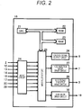
- FIG. 2 is a diagram illustrating an inner configuration of the control unit 16.
- the output values of the respective sensors such as the air flow sensor 2, the air-fuel ratio sensor 12 of the upstream of the catalyst, the accelerator opening sensor 13, the water temperature sensor 14, the crank angle sensor 15, the throttle opening sensor 17, the 02 sensor 20 of the downstream of the catalyst, the intake air temperature sensor 29, and a speed sensor are input.
- These output values are subjected to a signal processing such as noise removal by an input circuit 24 and then transmitted to an input/output port 25.
- the values of the input port is managed by a RAM 23, and subjected to a calculation processing in a CPU 21.
- a control program describing the content of the calculation processing is written in a ROM 22 in advance.
- An operation signal of the ignition plug 8 is set to an ON/OFF signal which is turned on at the time when the primary coil in an ignition output circuit is energized, and turned off at the time when the coil is de-energized.
- the ignition timing is a time to be turned off from on.
- a signal which is set to the output port for the ignition plug 8 is amplified for an ignition output circuit 26 to have energy enough for the combustion, and supplied to the ignition plug 8.
- a drive signal of the fuel injection valve 7 is set to an ON/OFF signal which is turned on at the time of opening and turned off at the time of closing.
- the drive signal is amplified for a fuel injection valve drive circuit 27 to have energy enough to open the fuel injection valve 7, and transmitted to the fuel injection valve 7.
- a drive signal to realize a target opening of the electronic throttle 3 is transmitted to the electronic throttle 3 through an electronic throttle drive circuit 28.
- a drive signal to realize a target opening of the EGR valve 19 is transmitted to the EGR valve 19 through an EGR valve drive circuit 30.
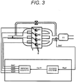
- FIG. 3 is a block diagram illustrating the entire control, which is configured by the following calculation units.
- the “rich cylinder detection unit” calculates the number (Cyl_R) of a cylinder of which the air-fuel ratio is richest.
- the “ignition timing calculation unit” calculates the ignition timings (Adv1 to Adv4) of the first to fourth cylinders.
- the ignition timing of the cylinder indicated by Cyl_R is advanced by a predetermined amount.
- Cyl_R (the number of the rich cylinder (excessive EGR)) is calculated. The details are illustrated in FIG. 4 .
- M_Rabf is a target air-fuel ratio in an air-fuel ratio feedback control or an average air-fuel ratio of all the cylinders.
- the calculation method of TP is a well-known technique, and obtained by the following formula using Qa (air amount) and Ne (rotation speed) for example.
- Qa air amount
- Ne rotation speed
- K is a calibration coefficient for the conversion to the torque equivalent value
- Cyl is the number of cylinders of the engine.
- the map M_Deg_R_Cyl1 is determined according to the engine specification, a position where the air-fuel ratio sensor is attached, and characteristics. The map may be determined from a prototype test.
- Adv1 to Adv4 ignition timings of the first to fourth cylinders
- Adv_hos asdvance angle correction amount
- FIG. 6 is a system diagram illustrating this embodiment. There is provided no external EGR system compared to the first embodiment ( FIG. 1 ). In addition, there are provided an intake valve 31 and an exhaust valve 32 of which the opening/closing timing is controllable. A drive signal is transmitted to the intake valve 31 and the exhaust valve 32 to realize a target opening/closing timing of the intake valve and the exhaust valve which is calculated by the control unit 16.
- the other configurations are the same as those of the first embodiment ( FIG. 1 ), and thus the details will not be described.
- FIG. 7 illustrates the inner configuration of the control unit 16, in which an intake valve drive circuit 33 and an exhaust valve drive circuit 34 are added to the first embodiment ( FIG. 2 ).
- the other configurations are the same as those of the first embodiment ( FIG. 1 ), and thus the details will not be described.
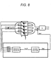
- FIG. 8 is a block diagram illustrating the entire control which is configured by the following calculation units.
- the “rich cylinder detection unit” calculates the number (Cyl_R) of a cylinder of which the air-fuel ratio is richest.
- the “conduction calculation unit” calculates conduction times (Dwell1 to Dwell4) toward ignition coils of the first to fourth cylinders.
- the conduction time toward the ignition coil of the cylinder indicated by Cyl_R is lengthened by a predetermined amount.
- Cyl_R the number of rich cylinder (excessive EGR)
- Cyl_R the number of rich cylinder (excessive EGR)
- FIG. 3 the details are the same as those of the first embodiment, and thus will not be described. Further, this process is performed when an inner EGR amount is equal to or more than a predetermined amount. Since there are a lot of well-known techniques about the inner EGR control, the details thereof will not be described.
- This calculation unit calculates Dwell1 to Dwell4 (the conduction times of the first to fourth cylinders). The details are illustrated in FIG. 9 .
- Dwell_hos (advance angle correction amount) may be changed according to the rich degree (according to an excessive EGR amount).
- FIG. 1 is a system diagram illustrating this embodiment. The configurations are the same as those of the first embodiment ( FIG. 1 ), and thus the details will not be described.
- FIG. 2 is a diagram illustrating the inner configuration of the control unit 16 which is the same as that of the first embodiment ( FIG. 2 ), and thus the details will not be described.
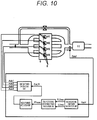
- FIG. 10 is a block diagram illustrating the entire control which is configured by the following calculation units.
- the "two-rotational component calculation unit” calculates a real part (R_2rev) and an imaginary part (I_2rev) of the two-rotational component of the signal (Rabf) of the air-fuel ratio sensor 12.
- the "two-rotational component phase calculation unit” calculates a two-rotational component phase (Phase) from R_2rev and I_2rev.
- the "rich cylinder detection unit” calculates the number (Cyl_R) of a cylinder of which the air-fuel ratio is richest.
- the “ignition timing calculation unit” calculates the ignition timings (Adv1 to Adv4) of the first to fourth cylinders.
- the ignition timing of the cylinder indicated by Cyl_R is advanced by a predetermined amount.
- the real part (R_2rev) and the imaginary part (I_2rev) of the two-rotational component of the signal (Rabf) of the air-fuel ratio sensor 12 are calculated.
- the details are illustrated in FIG. 11 .
- an external EGR amount is equal to or more than a predetermined amount, this process is performed.
- the external EGR control will not be described here in detail since there are a number of well-known techniques.
- a difference between a current value and a previous value of Rabf is calculated, and set to dRabf (a differential value of signals of the air-fuel ratio sensor of the upstream of the catalyst).
- the process (discrete Fourier transform) surrounded by a dotted line in the drawing is performed on dRabf.
- the current value, the previous value, a first value before the previous value, and a second value before the first value of C_R ⁇ dRabf are added and set to R_2rev.
- the current value, the previous value, a first value before the previous value, and a second value before the first value of C_I ⁇ dRabf are added and set to I_2rev.
- C_R and C_I are calculated according to CYLCNT (cylinder No.) as follows.
- CYLCNT is updated when a piston position of an N-th cylinder is at a predetermined value.
- the updating is performed at 110 deg before the compression TDC of the subject cylinder.
- Phase0 (a reference value of the two-rotational component phase) is obtained from R_2rev and I_2rev as follows. arctan 2 I_ 2 rev / R_ 2 rev ⁇ 180 / ⁇
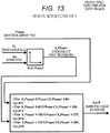
- Cyl_R (the number of the rich cylinder (excessive EGR)) is calculated using Phase. The details are illustrated in FIG. 13 . When an external EGR amount is equal to or more than a predetermined amount, this process is performed.
- the map M_K_Phase1 is determined according to the engine specification, a position where the air-fuel ratio sensor is attached, and characteristics.
- the map may be determined from a prototype test.
- Adv1 to Adv4 ignition timings of the first to fourth cylinders
- FIG. 1 is a system diagram illustrating this embodiment. The configurations are the same as those of the first embodiment ( FIG. 1 ), and thus the details will not be described.
- FIG. 2 is a diagram illustrating the inner configuration of the control unit 16 which is the same as that of the first embodiment ( FIG. 2 ), and thus the details will not be described.
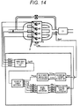
- FIG. 14 is a block diagram illustrating the entire control which is configured by the following calculation units.
- the "two-rotational component calculation unit” calculates a real part (R_2rev) and an imaginary part (I_2rev) of the two-rotational component of the signal (Rabf) of the air-fuel ratio sensor 12.
- the "two-rotational component phase calculation unit” calculates a two-rotational component phase (Phase) from R_2rev and I_2rev.
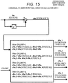
- the "individual-cylinder rotational variation calculation unit” calculates rotational variations (dNe_1, dNe_2, dNe_3, and dNe_4) of the cylinders from a signal of the crank angle sensor 15.
- the "unstable cylinder detection unit” calculates a cylinder (instability flags of the first to fourth cylinders) (f_dNe_1 to f_dNe_4) which becomes unstable by the excessive EGR amount from dNe_1, dNe_2, dNe_3, and dNe_4.
- the "excessive-EGR cylinder detection unit” calculates the number (Cyl_R) of the cylinder having a rich air-fuel ratio due to the most excessive EGR amount.
- the “ignition timing calculation unit” calculates the ignition timings (Adv1 to Adv4) of the first to fourth cylinders.
- the ignition timing of the cylinder indicated by Cyl_R is advanced by a predetermined amount.
- the real part (R_2rev) and the imaginary part (I_2rev) of the two-rotational component of the signal (Rabf) of the air-fuel ratio sensor 12 are calculated. While being illustrated in FIG. 11 , the details are the same as those of the third embodiment, and thus will not be described.
- the two-rotational component phase (Phase) is calculated. While being illustrated in FIG. 12 , the details are the same as those of the third embodiment, and thus will not be described.
- the rotational variations (dNe_1, dNe_2, dNe_3, and dNe_4) of the respective cylinder are calculated.
- the details are illustrated in FIG. 15 .
- the cylinders f_dNe_1 to f_dNe_4 (instability flags of the first to fourth cylinders) of which the stability is degraded due to the excessive EGR amount are detected using dNe_1, dNe_2, dNe_3, and dNe_4.
- the details are illustrated in FIG. 16 .
- an external EGR amount is equal to or more than a predetermined amount, this process is performed.
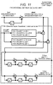
- Cyl_R (the number of the cylinder having the excessive EGR amount) is calculated using Phase and f_dNe_1 to f_dNe_4. The details are illustrated in FIG. 17 . When an external EGR amount is equal to or more than a predetermined amount, this process is performed.
- the map M_K_Phase1 is determined according to the engine specification, a position where the air-fuel ratio sensor is attached, and characteristics.
- the map may be determined from a prototype test.
- Adv1 to Adv4 ignition timings of the first to fourth cylinders
- FIG. 1 is a system diagram illustrating this embodiment. The other configurations are the same as those of the first embodiment ( FIG. 1 ), and thus the details will not be described.
- FIG. 2 is a diagram illustrating the inner configuration of the control unit 16 which is the same as that of the first embodiment ( FIG. 2 ), and thus the details will not be described.
- FIG. 3 is a block diagram illustrating the entire control, which is configured by the following calculation units.
- the “rich cylinder detection unit” calculates the number (Cyl_R) of a cylinder of which the air-fuel ratio is richest.
- the “ignition timing calculation unit” calculates the ignition timings (Adv1 to Adv4) of the first to fourth cylinders.
- the ignition timing of the cylinder indicated by Cyl_R is advanced by a predetermined amount.
- the ignition timings of the other cylinders are lagged by a predetermined amount.
- Cyl_R the number of rich cylinder (excessive EGR) is calculated. While being illustrated in FIG. 4 , the details are the same as those of the first embodiment, and thus will not be described.
- Adv1 to Adv4 ignition timings of the first to fourth cylinders
- Adv_hos asdvance angle correction amount
- Adv_hos_r lag angle correction amount
- the fuel injection amount of the cylinder other than the cylinder having the richest air-fuel ratio may be corrected to be increased.
- An engine control device of the invention controls, for example, a spark ignition engine which includes an EGR means to recirculate an exhaust to a combustion chamber, and an air-fuel-ratio detection means to detect an air-fuel ratio of each cylinder.
- the engine control device includes a means which corrects the ignition timing of the rich cylinder to be advanced or increases the ignition energy of the rich cylinder when the exhaust is recirculated by the EGR means and when the air-fuel ratio varies in the respective cylinders to be a rich air-fuel ratio and to be a lean air-fuel ratio compared to a predetermined value.
- the EGR amount (exhaust recirculating amount) varies among the cylinders by failure and aging of the EGR control system.
- the failure and the aging may include clogging, damage of components, and degradation. It may be considered a state where the variation in EGR amount occurs among the cylinders by an error of the EGR control system.
- G/F a ratio of a gas amount in the cylinder and a fuel amount
- the cylinder having an excessive EGR amount has a less air amount compare to the other cylinders.
- the air-fuel ratio control in the related art uniformly corrects the fuel injection amounts of all the cylinders such that the air-fuel ratio of the exhaust manifold integrated part becomes a target air-fuel ratio. Therefore, a cylinder which contains a less air amount but has the excessive EGR amount becomes relatively rich compared to the other cylinders.
- the richness of the air-fuel ratio of the subject cylinder is suppressed, but the air-fuel ratio becomes lean and thus the combustion stability is degraded still more. Since the cylinder having a rich air-fuel ratio due to the excessive EGR amount is lagged in the combustion speed, it is possible to be improved to be stable by advancing the ignition timing. In addition, since the cylinder having a rich air-fuel ratio due to the excessive EGR is lagged in the combustion speed, it is possible to be improved to be stable by increasing the ignition energy.
- a method of increasing the ignition energy a method of lengthening a spark ignition period and a method of reinforcing the current flowing to the ignition coil are considered.
- the EGR means is at least one of an external EGR means which recirculates the exhaust toward the intake side and an internal EGR means which controls the exhaust to be left in the combustion chamber or directly return.
- the EGR means which recirculates the exhaust to the combustion chamber is at least one of the external EGR means which recirculates the exhaust toward the intake side using a recirculation pipe, and the internal EGR means which controls, for example, an opening/closing period and a lift amount of intake and exhaust valves such that the exhaust is left in the combustion chamber or directly returns.
- the predetermined air-fuel ratio is a target air-fuel ratio or an average air-fuel ratio of all the cylinders in the air-fuel ratio feedback control.
- the rich cylinder is determined as a cylinder having an excessive EGR amount on the basis of the target air-fuel ratio in the air-fuel ratio feedback control or the average air-fuel ratio of all the cylinders.
- the engine control device of the invention includes at least a means which detects a combustion stability of the rich cylinder. When the combustion stability of the rich cylinder departs from a predetermined range, the engine control device corrects the ignition timing of the rich cylinder to be advanced or increases the ignition energy of the rich cylinder.
- the combustion stability is simultaneously degraded. At least the combustion stability of the rich cylinder is detected for each cylinder. When the richness and the combustion stability depart from a predetermined range, the subject cylinder is determined as stable due to the excessive EGR amount. Further, a combustion pressure, torque, and an angular acceleration are considered as the combustion stability.
- the engine control device of the invention includes at least a means which detects an angular acceleration of the rich cylinder.
- the engine control device corrects the ignition timing of the rich cylinder to be advanced or increases the ignition energy of the rich cylinder.
- the combustion stability is simultaneously degraded.
- the degradation of the combustion stability is detected by the angular acceleration of each cylinder.
- the richness and the angular acceleration are equal to or less than a predetermined value, the subject cylinder is determined to have the excessive EGR amount.
- the engine control device of the invention corrects the ignition timing of a cylinder other than the rich cylinder to be lagged, or corrects the fuel injection amount to be increased.
- the cylinder having the excessive EGR amount becomes rich
- the cylinder having a less EGR amount is increased in the air amount in proportion to being rich so as to become lean. Since a knock limit is shifted toward a lagged angle side due to the less EGR amount, the ignition timing of the subject cylinder is lagged. Alternatively, the leaning is released by correcting' the fuel injection amount to be increased.
Landscapes
- Engineering & Computer Science (AREA)
- Chemical & Material Sciences (AREA)
- Combustion & Propulsion (AREA)
- Mechanical Engineering (AREA)
- General Engineering & Computer Science (AREA)
- Signal Processing (AREA)
- Theoretical Computer Science (AREA)
- Oil, Petroleum & Natural Gas (AREA)
- Combined Controls Of Internal Combustion Engines (AREA)
- Electrical Control Of Air Or Fuel Supplied To Internal-Combustion Engine (AREA)
- Output Control And Ontrol Of Special Type Engine (AREA)
- Ignition Installations For Internal Combustion Engines (AREA)
- Electrical Control Of Ignition Timing (AREA)
Abstract
Description
- The present invention relates to a control device of an engine, and particularly to an ignition control device of a spark ignition engine.
- As a background technique in this related art, there is disclosed
JP 10-73068 A JP 2010-242630 A -
- PTL 1:
-
JP 10-73068 A - PTL 2:
-
JP 2010-242630 A -
PTL 1 fails in taking that a combustion performance is degraded due to the variation in EGR amount among the cylinders into consideration. - In addition, it is not possible in
PTL 2 that a cylinder causing a variation in EGR amount is specified to suppress the combustion stability from being degraded in every cylinder. - The invention has been made in view of the above problems, and an object thereof is to provide a spark ignition engine in which a cylinder causing a degradation of a combustion stability is specified when a variation in the EGR amount occurs among the cylinders, and suppresses the subject cylinder from being degraded in the combustion stability.
- In order to solve the above problems, the configurations disclosed in claims are employed for example.
- According to the invention, a cylinder having an excessive EGR amount is specified at the time when the EGR amount varies between the cylinders, and a parameter related to an ignition control of the subject cylinder is corrected to suppress the stability of the subject cylinder from being degraded.
-
- [
FIG. 1] FIG. 1 is a diagram of an engine control system in first, third, fourth, and fifth embodiments. - [
FIG. 2] FIG. 2 is a diagram illustrating an inner configuration of a control unit in the first, third, fourth, and fifth embodiments. - [
FIG. 3] FIG. 3 is a block diagram illustrating the entire control in the first and fifth embodiments. - [
FIG. 4] FIG. 4 is a block diagram of a rich cylinder detection unit in the first, second, and fifth embodiments. - [
FIG. 5] FIG. 5 is a block diagram of an ignition timing calculation unit in the first, third, and fourth embodiments. - [
FIG. 6] FIG. 6 is a diagram of the engine control system in the second embodiment. - [
FIG. 7] FIG. 7 is a diagram illustrating an inner configuration of the control unit in the second embodiment. - [
FIG. 8] FIG. 8 is a block diagram illustrating the entire control in the second embodiment. - [
FIG. 9] FIG. 9 is a block diagram of a conduction time calculation unit in the second embodiment. - [
FIG. 10] FIG. 10 is a block diagram illustrating the entire control in the third embodiment. - [
FIG. 11] FIG. 11 is a block diagram of a two-rotational component calculation unit in the third and fourth embodiments. - [
FIG. 12] FIG. 12 is a block diagram of a two-rotational component phase calculation unit in the third and fourth embodiments. - [
FIG. 13] FIG. 13 is a block diagram of a rich cylinder detection unit in the third embodiment. - [
FIG. 14] FIG. 14 is a block diagram illustrating the entire control in the fourth embodiment. - [
FIG. 15] FIG. 15 is a block diagram of an individual-cylinder rotational variation calculation unit in the fourth embodiment. - [
FIG. 16] FIG. 16 is a block diagram of an unstable cylinder detection unit in the fourth embodiment. - [
FIG. 17] FIG. 17 is a block diagram of an excessive-EGR cylinder detection unit in the fourth embodiment. - [
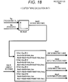
FIG. 18] FIG. 18 is a block diagram of an ignition timing calculation unit in the fifth embodiment. - [
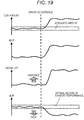
FIG. 19] FIG. 19 is profiles of EGR amount, G/F, A/F, and instability of a specific cylinder at the time when a failure occurs in an EGR control system. - Hereinafter, embodiments will be described using the drawings.
- In this embodiment, the description will be given about an example in which a cylinder having the richest air-fuel ratio is detected using an air-fuel ratio sensor of an exhaust manifold integrated part at the time of executing the external EGR, and an ignition timing of the subject cylinder is advanced.
-
FIG. 1 is a system diagram illustrating this embodiment. In a multi-cylinder engine 9 (herein, four cylinders), the air from the outside passes through anair cleaner 1, and flows into the cylinder via anintake manifold 4 and acollector 5. An intake amount of air is adjusted by anelectronic throttle 3. The intake amount of air is detected by anair flow sensor 2. In addition, an intake air temperature is detected by an intakeair temperature sensor 29. In acrank angle sensor 15, a signal is output every rotation angle of 10° of a crank shaft and every combustion period. Awater temperature sensor 14 detects a coolant temperature of theengine 9. In addition, anaccelerator opening sensor 13 detects a stepping amount of an accelerator 6, and thus detects a demand torque of a driver. - The signals of the
accelerator opening sensor 13, theair flow sensor 2, the intakeair temperature sensor 29, and athrottle opening sensor 17 attached to theelectronic throttle 3, thecrank angle sensor 15, thewater temperature sensor 14 are transmitted to acontrol unit 16 described below. An operation state of theengine 9 is obtained from these sensor outputs, and an air amount, a fuel injection amount, an ignition timing, and a main operation amount of theengine 9 of an EGR amount are optimally calculated. - A target air amount calculated in the
control unit 16 is converted from a target throttle opening to an electronic throttle drive signal, and transmitted to theelectronic throttle 3. The fuel injection amount is converted into a value opening pulse signal, and transmitted to a fuel injection valve (injector) 7. In addition, a drive signal to be ignited at the ignition timing calculated by thecontrol unit 16 is transmitted to anignition plug 8. In addition, a drive signal is transmitted to anEGR valve 19 such that a target EGR amount calculated by thecontrol unit 16 is executed. - The injected fuel is mixed with the air from the intake manifold, and flows into the cylinder of the
engine 9 so as to form an air-fuel mixture. The air-fuel mixture is exploded by a spark generated from theignition plug 8 at a predetermined ignition timing. The piston is pushed down by the combustion pressure to be power of theengine 9. The exhaust after the explosion is sent to a three-way catalyst 11 through anexhaust manifold 10. Part of the exhaust is recirculated to the intake side through an exhaust recirculatingpipe 18. The amount of recirculation is controlled by theEGR valve 19. - The air-
fuel ratio sensor 12 of the upstream of the catalyst is attached between theengine 9 and the three-way catalyst 11. The 02sensor 20 of the downstream of the catalyst is attached on the downstream side of the three-way catalyst 11. -
FIG. 2 is a diagram illustrating an inner configuration of thecontrol unit 16. In anECU 16, the output values of the respective sensors such as theair flow sensor 2, the air-fuel ratio sensor 12 of the upstream of the catalyst, theaccelerator opening sensor 13, thewater temperature sensor 14, thecrank angle sensor 15, thethrottle opening sensor 17, the 02sensor 20 of the downstream of the catalyst, the intakeair temperature sensor 29, and a speed sensor are input. These output values are subjected to a signal processing such as noise removal by aninput circuit 24 and then transmitted to an input/output port 25. The values of the input port is managed by aRAM 23, and subjected to a calculation processing in aCPU 21. A control program describing the content of the calculation processing is written in aROM 22 in advance. The values indicating the respective actuator operation amounts calculated according to the control program are stored in theRAM 23, and then transmitted to the input/output port 25. An operation signal of theignition plug 8 is set to an ON/OFF signal which is turned on at the time when the primary coil in an ignition output circuit is energized, and turned off at the time when the coil is de-energized. The ignition timing is a time to be turned off from on. A signal which is set to the output port for theignition plug 8 is amplified for anignition output circuit 26 to have energy enough for the combustion, and supplied to theignition plug 8. In addition, a drive signal of thefuel injection valve 7 is set to an ON/OFF signal which is turned on at the time of opening and turned off at the time of closing. The drive signal is amplified for a fuel injectionvalve drive circuit 27 to have energy enough to open thefuel injection valve 7, and transmitted to thefuel injection valve 7. A drive signal to realize a target opening of theelectronic throttle 3 is transmitted to theelectronic throttle 3 through an electronicthrottle drive circuit 28. A drive signal to realize a target opening of theEGR valve 19 is transmitted to theEGR valve 19 through an EGRvalve drive circuit 30. - Hereinafter, the description will be given about the control program written in the
ROM 22.FIG. 3 is a block diagram illustrating the entire control, which is configured by the following calculation units. - • Rich cylinder detection unit (
FIG. 4 ) - • Ignition timing calculation unit (
FIG. 5 ) - The "rich cylinder detection unit" calculates the number (Cyl_R) of a cylinder of which the air-fuel ratio is richest. The "ignition timing calculation unit" calculates the ignition timings (Adv1 to Adv4) of the first to fourth cylinders. The ignition timing of the cylinder indicated by Cyl_R is advanced by a predetermined amount. Hereinafter, the details of the respective calculation units will be described.
- In this calculation unit, Cyl_R (the number of the rich cylinder (excessive EGR)) is calculated. The details are illustrated in
FIG. 4 . - When an external EGR amount is equal to or more than a predetermined amount, this process is performed. The external EGR control will not be described here in detail since there are a number of well-known techniques.
- • The engine rotation angle (from a reference angle) is set to Deg_R when Rabf satisfies Rabf < M_Rabf and is minimized during a period of the engine rotates twice. The reference angle may be a predetermined angle such as an intake TDC of a specific cylinder.
- • A value obtained with reference to a map M_Deg_R_Cyl1 using TP (torque equivalent value) and Ne (rotation speed) is set to Deg_R_Cyl1 (a threshold value of the engine rotation angle at the time of being rich).
- • When Deg_R_Cyl1 ≤ Deg_R < Deg_R_Cyl1 + 180, Cyl_R = 1 When Deg_R_Cyl1 + 180 ≤ Deg_R < Deg_R_Cyl1 + 360, Cyl_R = 3 When Deg_R_Cyl1 + 360 ≤ Deg_R < Deg_R_Cyl1 + 540, Gyl_R = 4 When Deg_R_Cyl1 + 540 ≤ Deg_R < Deg_R_Cyl1 + 720, Cyl_R = 2
- M_Rabf is a target air-fuel ratio in an air-fuel ratio feedback control or an average air-fuel ratio of all the cylinders.
- The calculation method of TP is a well-known technique, and obtained by the following formula using Qa (air amount) and Ne (rotation speed) for example.

- Herein, K is a calibration coefficient for the conversion to the torque equivalent value, and Cyl is the number of cylinders of the engine. The map M_Deg_R_Cyl1 is determined according to the engine specification, a position where the air-fuel ratio sensor is attached, and characteristics. The map may be determined from a prototype test.
- In this calculation unit, Adv1 to Adv4 (ignition timings of the first to fourth cylinders) are calculated. The details are illustrated in
FIG. 5 . - • A value obtained with reference to a map M_Adv0 using TP (torque equivalent value) and Ne (rotation speed) is set to Adv0 (reference ignition timing).
- • When Cyl_R = 1


- Further, since a minimum value of Rabf (air-fuel ratio) obtained by the rich cylinder detection unit is a rich degree, Adv_hos (advance angle correction amount) may be changed according to the rich degree (according to an excessive EGR amount).
- In this embodiment, the description will be given about an example in which a cylinder having the richest air-fuel ratio is detected using the air-fuel ratio sensor of the exhaust manifold integrated part at the time of performing the inner EGR, and an ignition energy of the subject cylinder is increased.
-
FIG. 6 is a system diagram illustrating this embodiment. There is provided no external EGR system compared to the first embodiment (FIG. 1 ). In addition, there are provided anintake valve 31 and anexhaust valve 32 of which the opening/closing timing is controllable. A drive signal is transmitted to theintake valve 31 and theexhaust valve 32 to realize a target opening/closing timing of the intake valve and the exhaust valve which is calculated by thecontrol unit 16. The other configurations are the same as those of the first embodiment (FIG. 1 ), and thus the details will not be described. -
FIG. 7 illustrates the inner configuration of thecontrol unit 16, in which an intakevalve drive circuit 33 and an exhaustvalve drive circuit 34 are added to the first embodiment (FIG. 2 ). The other configurations are the same as those of the first embodiment (FIG. 1 ), and thus the details will not be described. - Hereinafter, the description will be given about the control program written in the
ROM 22.FIG. 8 is a block diagram illustrating the entire control which is configured by the following calculation units. - • Rich cylinder detection unit (
FIG. 4 ) - • Conduction time calculation unit (
FIG. 9 ) - The "rich cylinder detection unit" calculates the number (Cyl_R) of a cylinder of which the air-fuel ratio is richest. The "conduction calculation unit" calculates conduction times (Dwell1 to Dwell4) toward ignition coils of the first to fourth cylinders. The conduction time toward the ignition coil of the cylinder indicated by Cyl_R is lengthened by a predetermined amount. Hereinafter, the details of the respective calculation units will be described.
- In this calculation unit, Cyl_R (the number of rich cylinder (excessive EGR)) is calculated. While being illustrated in
FIG. 3 , the details are the same as those of the first embodiment, and thus will not be described. Further, this process is performed when an inner EGR amount is equal to or more than a predetermined amount. Since there are a lot of well-known techniques about the inner EGR control, the details thereof will not be described. - This calculation unit calculates Dwell1 to Dwell4 (the conduction times of the first to fourth cylinders). The details are illustrated in
FIG. 9 . - • A value obtained with reference to a map M_Dwell0 using TP (torque equivalent value) and Ne (rotation speed) is set to Dwell0 (reference conduction time).
- • When Cyl_R = 1


- Further, since a minimum value of Rabf (air-fuel ratio) obtained by the rich cylinder detection unit is a rich degree, Dwell_hos (advance angle correction amount) may be changed according to the rich degree (according to an excessive EGR amount).
- In this embodiment, the description will be given about an example in which a cylinder having the richest air-fuel ratio is detected using a two-rotational frequency component of the engine in the signals of the air-fuel ratio sensors of the exhaust manifold integrated part at the time of executing the external EGR, and the ignition timing of the subject cylinder is advanced.
-
FIG. 1 is a system diagram illustrating this embodiment. The configurations are the same as those of the first embodiment (FIG. 1 ), and thus the details will not be described. -
FIG. 2 is a diagram illustrating the inner configuration of thecontrol unit 16 which is the same as that of the first embodiment (FIG. 2 ), and thus the details will not be described. - Hereinafter, the description will be given about the control program written in the
ROM 22.FIG. 10 is a block diagram illustrating the entire control which is configured by the following calculation units. - • Two-rotational component calculation unit (
FIG. 11 ) - • Two-rotational component phase calculation unit (
FIG. 12 ) - • Rich cylinder detection unit (
FIG. 13 ) - • Ignition timing calculation unit (
FIG. 5 ) - The "two-rotational component calculation unit" calculates a real part (R_2rev) and an imaginary part (I_2rev) of the two-rotational component of the signal (Rabf) of the air-
fuel ratio sensor 12. The "two-rotational component phase calculation unit" calculates a two-rotational component phase (Phase) from R_2rev and I_2rev. The "rich cylinder detection unit" calculates the number (Cyl_R) of a cylinder of which the air-fuel ratio is richest. The "ignition timing calculation unit" calculates the ignition timings (Adv1 to Adv4) of the first to fourth cylinders. The ignition timing of the cylinder indicated by Cyl_R is advanced by a predetermined amount. Hereinafter, the details of the respective calculation units will be described. - In this calculation unit, the real part (R_2rev) and the imaginary part (I_2rev) of the two-rotational component of the signal (Rabf) of the air-
fuel ratio sensor 12 are calculated. The details are illustrated inFIG. 11 . When an external EGR amount is equal to or more than a predetermined amount, this process is performed. The external EGR control will not be described here in detail since there are a number of well-known techniques. - A difference between a current value and a previous value of Rabf is calculated, and set to dRabf (a differential value of signals of the air-fuel ratio sensor of the upstream of the catalyst). The process (discrete Fourier transform) surrounded by a dotted line in the drawing is performed on dRabf. The current value, the previous value, a first value before the previous value, and a second value before the first value of C_R × dRabf are added and set to R_2rev. In addition, the current value, the previous value, a first value before the previous value, and a second value before the first value of C_I × dRabf are added and set to I_2rev. Herein, C_R and C_I are calculated according to CYLCNT (cylinder No.) as follows. CYLCNT is updated when a piston position of an N-th cylinder is at a predetermined value. Herein, it is assumed that the updating is performed at 110 deg before the compression TDC of the subject cylinder.
- When CYLCNT = 1, C_R = 1
- When CYLCNT = 3 or 2, C_R = 0
- When CYLCNT = 4, C_R = -1
- When CYLCNT = 1 or 4, C_I = 0
- When CYLCNT = 3, C_I = 1
- When CYLCNT = 2, C_I = -1
- When a difference between the current value and the previous value of Rabf is subjected to the Fourier transform, it is possible to detect a cylinder having a relatively rich air-fuel ratio among all the cylinders (a cylinder having an air-fuel ratio richer than an average value of all the cylinders).
- In this calculation unit, the two-rotational component phase (Phase) is calculated. The details are illustrated in
FIG. 12 . When an external EGR amount is equal to or more than a predetermined amount, this process is performed. Phase0 (a reference value of the two-rotational component phase) is obtained from R_2rev and I_2rev as follows.
- Herein, arctan2 calculates an arc tangent value (= phase) corresponding to four quadrants (-180 to 180 deg).
- Further, Phase (two-rotational component phase) having a phase range of 0 to 360 deg is obtained. Specifically, Phase = Phase0 + 360 is set at the time of Phase0 < 0, and Phase = Phase0 at the other time.
- In this calculation unit, Cyl_R (the number of the rich cylinder (excessive EGR)) is calculated using Phase. The details are illustrated in
FIG. 13 . When an external EGR amount is equal to or more than a predetermined amount, this process is performed. - • A value obtained with reference to a map M_K_Phase1 using TP (torque equivalent value) and Ne (rotation speed) is set to K_Phase1 (threshold value of the phase at the time of being rich).
- • When K_Phase1 ≤ Phase < K_Phase1 + 90, Cyl_R = 1 When K_Phase1 + 90 ≤ Phase < K_Phase1 + 180, Cyl_R = 3 When K_Phase1 + 180 ≤ Phase < K_Phase1 + 270, Cyl_R = 4 When K_Phase1 + 270 ≤ Phase < K_Phase1 + 360, Cyl_R = 2
- The map M_K_Phase1 is determined according to the engine specification, a position where the air-fuel ratio sensor is attached, and characteristics. The map may be determined from a prototype test.
- In this calculation unit, Adv1 to Adv4 (ignition timings of the first to fourth cylinders) are calculated. While being illustrated in
FIG. 5 , the details are the same as those of the first embodiment, and thus will not be described. - In this embodiment, the description will be given about an example in which a cylinder having an excessive EGR amount is detected using both the air-fuel ratio sensor of the exhaust manifold integrated part and the crank angle sensor at the time of executing the external EGR, and the ignition timing of the subject cylinder is advanced.
-
FIG. 1 is a system diagram illustrating this embodiment. The configurations are the same as those of the first embodiment (FIG. 1 ), and thus the details will not be described. -
FIG. 2 is a diagram illustrating the inner configuration of thecontrol unit 16 which is the same as that of the first embodiment (FIG. 2 ), and thus the details will not be described. - Hereinafter, the description will be given about the control program written in the
ROM 22.FIG. 14 is a block diagram illustrating the entire control which is configured by the following calculation units. - • Two-rotational component calculation unit (
FIG. 11 ) - • Two-rotational component phase calculation unit (
FIG. 12 ) - • Individual-cylinder rotational variation calculation unit (
FIG. 15 ) - • Unstable cylinder detection unit (
FIG. 16 ) - • Excessive-EGR cylinder detection unit (
FIG. 17 ) - • Ignition timing calculation unit (
FIG. 5 ) - The "two-rotational component calculation unit" calculates a real part (R_2rev) and an imaginary part (I_2rev) of the two-rotational component of the signal (Rabf) of the air-
fuel ratio sensor 12. The "two-rotational component phase calculation unit" calculates a two-rotational component phase (Phase) from R_2rev and I_2rev. The "individual-cylinder rotational variation calculation unit" calculates rotational variations (dNe_1, dNe_2, dNe_3, and dNe_4) of the cylinders from a signal of thecrank angle sensor 15. The "unstable cylinder detection unit" calculates a cylinder (instability flags of the first to fourth cylinders) (f_dNe_1 to f_dNe_4) which becomes unstable by the excessive EGR amount from dNe_1, dNe_2, dNe_3, and dNe_4. The "excessive-EGR cylinder detection unit" calculates the number (Cyl_R) of the cylinder having a rich air-fuel ratio due to the most excessive EGR amount. The "ignition timing calculation unit" calculates the ignition timings (Adv1 to Adv4) of the first to fourth cylinders. The ignition timing of the cylinder indicated by Cyl_R is advanced by a predetermined amount. Hereinafter, the details of the respective calculation units will be described. Hereinafter, the details of the respective calculation units will be described. - In this calculation unit, the real part (R_2rev) and the imaginary part (I_2rev) of the two-rotational component of the signal (Rabf) of the air-
fuel ratio sensor 12 are calculated. While being illustrated inFIG. 11 , the details are the same as those of the third embodiment, and thus will not be described. - In this calculation unit, the two-rotational component phase (Phase) is calculated. While being illustrated in
FIG. 12 , the details are the same as those of the third embodiment, and thus will not be described. - In this calculation unit, the rotational variations (dNe_1, dNe_2, dNe_3, and dNe_4) of the respective cylinder are calculated. The details are illustrated in
FIG. 15 . When an external EGR amount is equal to or more than a predetermined amount, this process is performed. - • A difference between the current value and the previous value of Ne (rotation speed) is calculated, and set to dNe (rotational variation).
- • When CYLCNT = 1,
- dNe_1 = dNe_1 (previous value), dNe_2 = dNe_2 (previous value)
- dNe_3 = dNe_3 (previous value), dNe_4 = dNe When CYLCNT = 2,
- dNe_1 = dNe_1 (previous value), dNe_2 = dNe_2 (previous value)
- dNe_3 = dNe, dNe_4 = dNe_4 (previous value) When CYLCNT = 3,
- dNe_1 = dNe_1 (previous value), dNe_2 = dNe
- dNe_3= dNe_3 (previous value), dNe_4 = dNe_4 (previous value)
- dNe_1 = dNe, dNe_2 = dNe_2 (previous value)
- dNe_3 = dNe_3 (previous value), dNe_4 = 4dNe_4 (previous value)
- dNe_1: Rotational variation of the first cylinder
- dNe_2: Rotational variation of the second cylinder
- dNe_3: Rotational variation of the third cylinder
- dNe_4: Rotational variation of the fourth cylinder
- In this calculation unit, the cylinders f_dNe_1 to f_dNe_4 (instability flags of the first to fourth cylinders) of which the stability is degraded due to the excessive EGR amount are detected using dNe_1, dNe_2, dNe_3, and dNe_4. The details are illustrated in
FIG. 16 . When an external EGR amount is equal to or more than a predetermined amount, this process is performed. - • The cylinders are initialized to f_dNe_1 = 0, f_dNe_2 = 0, f_dNe_3 = 0, and f_dNe_4 = 0.
- When dNe_1 ≤ k_dNe, f_dNe_1 = 1
- When dNe_2 ≤ k_dNe, f_dNe_2 = 1
- • When dNe_3 ≤ k_dNe, f_dNe_3 = 1
- When dNe_4 ≤ k_dNe, f_dNe_4 = 1
- In this calculation unit, Cyl_R (the number of the cylinder having the excessive EGR amount) is calculated using Phase and f_dNe_1 to f_dNe_4. The details are illustrated in
FIG. 17 . When an external EGR amount is equal to or more than a predetermined amount, this process is performed. - • A value obtained with reference to a map M_K_Phase1 using TP (torque equivalent value) and Ne (rotation speed) is set to K_Phase1 (threshold value of the phase at the time of being rich).
- • When K_Phase1 ≤ Phase < K_Phase1 + 90 and f_dNe_1 = 1, Cyl_R = 1
- The map M_K_Phase1 is determined according to the engine specification, a position where the air-fuel ratio sensor is attached, and characteristics. The map may be determined from a prototype test.
- In this calculation unit, Adv1 to Adv4 (ignition timings of the first to fourth cylinders) are calculated. While being illustrated in
FIG. 5 , the details are the same as those of the first embodiment, and thus will not be described. - In this embodiment, the description will be given about an example in which a cylinder having the richest air-fuel ratio is detected using an air-fuel ratio sensor of an exhaust manifold integrated part at the time of executing the external EGR, the ignition timing of the subject cylinder is advanced, and the ignition timings of the other cylinders are lagged.
-
FIG. 1 is a system diagram illustrating this embodiment. The other configurations are the same as those of the first embodiment (FIG. 1 ), and thus the details will not be described. -
FIG. 2 is a diagram illustrating the inner configuration of thecontrol unit 16 which is the same as that of the first embodiment (FIG. 2 ), and thus the details will not be described. - Hereinafter, the description will be given about the control program written in the
ROM 22.FIG. 3 is a block diagram illustrating the entire control, which is configured by the following calculation units. - • Rich cylinder detection unit (
FIG. 4 ) - • Ignition timing calculation unit (
FIG. 5 ) - The "rich cylinder detection unit" calculates the number (Cyl_R) of a cylinder of which the air-fuel ratio is richest. The "ignition timing calculation unit" calculates the ignition timings (Adv1 to Adv4) of the first to fourth cylinders. The ignition timing of the cylinder indicated by Cyl_R is advanced by a predetermined amount. The ignition timings of the other cylinders are lagged by a predetermined amount. Hereinafter, the details of the respective calculation units will be described.
- In this calculation unit, Cyl_R (the number of rich cylinder (excessive EGR)) is calculated. While being illustrated in
FIG. 4 , the details are the same as those of the first embodiment, and thus will not be described. - In this calculation unit, Adv1 to Adv4 (ignition timings of the first to fourth cylinders) are calculated. The details are illustrated in
FIG. 18 . - • A value obtained with reference to a map M_Adv0 using TP (torque equivalent value) and Ne (rotation speed) is set to Adv0 (reference ignition timing).
- • When Cyl_R = 1


- Further, since a minimum value of Rabf (air-fuel ratio) obtained by the rich cylinder detection unit is a rich degree, Adv_hos (advance angle correction amount) and Adv_hos_r (lag angle correction amount) may be changed according to the rich degree (according to an excessive EGR amount). In addition, the fuel injection amount of the cylinder other than the cylinder having the richest air-fuel ratio may be corrected to be increased.
- The effects of the configuration of the invention are as follows. An engine control device of the invention controls, for example, a spark ignition engine which includes an EGR means to recirculate an exhaust to a combustion chamber, and an air-fuel-ratio detection means to detect an air-fuel ratio of each cylinder. The engine control device includes a means which corrects the ignition timing of the rich cylinder to be advanced or increases the ignition energy of the rich cylinder when the exhaust is recirculated by the EGR means and when the air-fuel ratio varies in the respective cylinders to be a rich air-fuel ratio and to be a lean air-fuel ratio compared to a predetermined value.
- In other words, in a case where the EGR is performed to recirculate the exhaust to the combustion chamber, the EGR amount (exhaust recirculating amount) varies among the cylinders by failure and aging of the EGR control system. Herein, examples of the failure and the aging may include clogging, damage of components, and degradation. It may be considered a state where the variation in EGR amount occurs among the cylinders by an error of the EGR control system. As illustrated in
FIG. 19 , when a cylinder has an excessive EGR amount due to the variation in EGR amount among the cylinders, G/F (a ratio of a gas amount in the cylinder and a fuel amount) becomes large, and the stability is degraded. On the other hand, the cylinder having an excessive EGR amount has a less air amount compare to the other cylinders. The air-fuel ratio control in the related art uniformly corrects the fuel injection amounts of all the cylinders such that the air-fuel ratio of the exhaust manifold integrated part becomes a target air-fuel ratio. Therefore, a cylinder which contains a less air amount but has the excessive EGR amount becomes relatively rich compared to the other cylinders. - In a case where only the fuel injection amount of the subject cylinder is reduced, the richness of the air-fuel ratio of the subject cylinder is suppressed, but the air-fuel ratio becomes lean and thus the combustion stability is degraded still more. Since the cylinder having a rich air-fuel ratio due to the excessive EGR amount is lagged in the combustion speed, it is possible to be improved to be stable by advancing the ignition timing. In addition, since the cylinder having a rich air-fuel ratio due to the excessive EGR is lagged in the combustion speed, it is possible to be improved to be stable by increasing the ignition energy. Herein, as a method of increasing the ignition energy, a method of lengthening a spark ignition period and a method of reinforcing the current flowing to the ignition coil are considered.
- In addition, in the engine control device of the invention, the EGR means is at least one of an external EGR means which recirculates the exhaust toward the intake side and an internal EGR means which controls the exhaust to be left in the combustion chamber or directly return.
- In other words, the EGR means which recirculates the exhaust to the combustion chamber is at least one of the external EGR means which recirculates the exhaust toward the intake side using a recirculation pipe, and the internal EGR means which controls, for example, an opening/closing period and a lift amount of intake and exhaust valves such that the exhaust is left in the combustion chamber or directly returns.
- In addition, in the engine control device of the invention, the predetermined air-fuel ratio is a target air-fuel ratio or an average air-fuel ratio of all the cylinders in the air-fuel ratio feedback control.
- In other words, due to a variation of the EGR amount among the cylinders, the air-fuel ratio varies between a rich side and a lean side around the target air-fuel ratio in the air-fuel ratio feedback control or an air-fuel ratio of all the cylinders which is substantially equivalent to the target air-fuel ratio. Therefore, the rich cylinder is determined as a cylinder having an excessive EGR amount on the basis of the target air-fuel ratio in the air-fuel ratio feedback control or the average air-fuel ratio of all the cylinders.
- In addition, the engine control device of the invention includes at least a means which detects a combustion stability of the rich cylinder. When the combustion stability of the rich cylinder departs from a predetermined range, the engine control device corrects the ignition timing of the rich cylinder to be advanced or increases the ignition energy of the rich cylinder.
- In other words, as described above, when the cylinder having the excessive EGR amount becomes rich, the combustion stability is simultaneously degraded. At least the combustion stability of the rich cylinder is detected for each cylinder. When the richness and the combustion stability depart from a predetermined range, the subject cylinder is determined as stable due to the excessive EGR amount. Further, a combustion pressure, torque, and an angular acceleration are considered as the combustion stability.
- In addition, the engine control device of the invention includes at least a means which detects an angular acceleration of the rich cylinder. When the angular acceleration of the rich cylinder is equal to or less than a predetermined value, the engine control device corrects the ignition timing of the rich cylinder to be advanced or increases the ignition energy of the rich cylinder.
- In other words, as described above, when the cylinder having the excessive EGR amount becomes rich, the combustion stability is simultaneously degraded. The degradation of the combustion stability is detected by the angular acceleration of each cylinder. When the richness and the angular acceleration are equal to or less than a predetermined value, the subject cylinder is determined to have the excessive EGR amount.
- In addition, the engine control device of the invention corrects the ignition timing of a cylinder other than the rich cylinder to be lagged, or corrects the fuel injection amount to be increased.
- In other words, while the cylinder having the excessive EGR amount becomes rich, the cylinder having a less EGR amount is increased in the air amount in proportion to being rich so as to become lean. Since a knock limit is shifted toward a lagged angle side due to the less EGR amount, the ignition timing of the subject cylinder is lagged. Alternatively, the leaning is released by correcting' the fuel injection amount to be increased.
-
- 1
- air cleaner
- 2
- air flow sensor
- 3
- electronic throttle
- 4
- intake manifold
- 5
- collector
- 6
- accelerator
- 7
- fuel injection valve
- 8
- ignition plug
- 9
- engine
- 10
- exhaust manifold
- 11
- three-way catalyst
- 12
- air-fuel ratio sensor of upstream of catalyst
- 13
- accelerator opening sensor
- 14
- water temperature sensor
- 15
- crank angle sensor
- 16
- control unit
- 17
- throttle opening sensor
- 18
- exhaust recirculating pipe
- 19
- EGR valve
- 20
- 02 sensor of downstream of catalyst
- 21
- CPU
- 22
- ROM
- 23
- RAM
- 24
- input circuit
- 25
- input/output port
- 26
- ignition output circuit
- 27
- fuel injection valve drive circuit
- 28
- electronic throttle drive circuit
- 29
- intake air temperature sensor
- 30
- EGR valve drive circuit
- 31
- intake valve
- 32
- exhaust valve
- 33
- intake valve drive circuit
- 34
- exhaust valve drive circuit
When K_Phase1 + 180 ≤ Phase < K_Phase1 + 270 and
When K_Phase1 + 270 ≤ Phase < K_Phase1 + 360 and f_dNe_2 = 1, Cyl_R = 2
Claims (7)
- An engine control device that controls a spark ignition engine equipped with an EGR device to recirculate an exhaust to a combustion chamber, and detects an air-fuel ratio of each cylinder,
wherein, when the exhaust is recirculated by the EGR device and an air-fuel ratio of each cylinder varies between a rich air-fuel ratio and a lean air-fuel ratio,
an ignition timing of a cylinder having the rich air-fuel ratio is corrected to be advanced, or an ignition energy of the cylinder having the rich air-fuel ratio is increased. - The engine control device according to claim 1,
wherein the EGR device is at least one of
an external EGR device that recirculates the exhaust toward an intake side through an exhaust recirculating pipe, and
an inner EGR device that controls an intake valve and an exhaust valve such that the exhaust is left in the combustion chamber or directly returns. - The engine control device according to claim 1,
wherein the predetermined air-fuel ratio is a target air-fuel ratio in an air-fuel ratio feedback control or an average air-fuel ratio of all the cylinders. - The engine control device according to claim 1,
wherein, when a combustion stability of the cylinder having the rich air-fuel ratio departs from a predetermined range,
the ignition timing of the cylinder having the rich air-fuel ratio is corrected to be advanced, or the ignition energy of the cylinder having the rich air-fuel ratio is increased. - The engine control device according to claim 1,
wherein, when an angular acceleration of the cylinder having the rich air-fuel ratio is equal to or less than a predetermined value,
the ignition timing of the cylinder having the rich air-fuel ratio is corrected to be advanced, or the ignition energy of the cylinder having the rich air-fuel ratio is increased. - The engine control device according to claim 1,
wherein the ignition timing of a cylinder other than the cylinder having the rich air-fuel ratio is corrected to be lagged, or a fuel injection amount is corrected to be increased. - The engine control device according to claim 1,
wherein a correction amount of the ignition timing of the cylinder having the rich air-fuel ratio to be advanced or an increasing amount of the ignition energy of the cylinder having the rich air-fuel ratio is changed on the basis of a degree of a variation in air-fuel ratio of each cylinder.
Applications Claiming Priority (2)
| Application Number | Priority Date | Filing Date | Title |
|---|---|---|---|
| JP2014216812A JP6462311B2 (en) | 2014-10-24 | 2014-10-24 | Engine control device |
| PCT/JP2015/075148 WO2016063639A1 (en) | 2014-10-24 | 2015-09-04 | Engine control device |
Publications (3)
| Publication Number | Publication Date |
|---|---|
| EP3211214A1 true EP3211214A1 (en) | 2017-08-30 |
| EP3211214A4 EP3211214A4 (en) | 2018-07-18 |
| EP3211214B1 EP3211214B1 (en) | 2019-07-31 |
Family
ID=55760684
Family Applications (1)
| Application Number | Title | Priority Date | Filing Date |
|---|---|---|---|
| EP15853028.7A Active EP3211214B1 (en) | 2014-10-24 | 2015-09-04 | Engine control device |
Country Status (5)
| Country | Link |
|---|---|
| US (1) | US10697383B2 (en) |
| EP (1) | EP3211214B1 (en) |
| JP (1) | JP6462311B2 (en) |
| CN (1) | CN107076097B (en) |
| WO (1) | WO2016063639A1 (en) |
Families Citing this family (4)
| Publication number | Priority date | Publication date | Assignee | Title |
|---|---|---|---|---|
| JP2018115555A (en) * | 2017-01-16 | 2018-07-26 | 本田技研工業株式会社 | Control device for internal combustion engine |
| JP7087609B2 (en) * | 2018-04-11 | 2022-06-21 | トヨタ自動車株式会社 | Engine control unit |
| CN113286940A (en) | 2019-01-15 | 2021-08-20 | 三菱重工发动机和增压器株式会社 | Engine operating state determination device, vehicle, and engine operating state determination method |
| JP7200857B2 (en) * | 2019-07-01 | 2023-01-10 | マツダ株式会社 | Engine combustion control device |
Family Cites Families (16)
| Publication number | Priority date | Publication date | Assignee | Title |
|---|---|---|---|---|
| JPH1073068A (en) | 1996-08-29 | 1998-03-17 | Honda Motor Co Ltd | Ignition timing control device for internal combustion engine |
| JP2001271691A (en) * | 2000-03-27 | 2001-10-05 | Mazda Motor Corp | Engine exhaust purification device |
| WO2002103181A1 (en) | 2001-06-18 | 2002-12-27 | Toyota Jidosha Kabushiki Kaisha | Air-fuel ratio controller of internal combustion engine |
| US6725830B2 (en) * | 2002-06-04 | 2004-04-27 | Ford Global Technologies, Llc | Method for split ignition timing for idle speed control of an engine |
| JP4239584B2 (en) | 2002-12-24 | 2009-03-18 | 日産自動車株式会社 | Ignition timing control device for in-cylinder direct injection spark ignition engine |
| JP4466008B2 (en) | 2003-07-31 | 2010-05-26 | 日産自動車株式会社 | Engine fuel injection control device |
| JP2006161691A (en) * | 2004-12-07 | 2006-06-22 | Toyota Motor Corp | Internal combustion engine |
| JP4788632B2 (en) * | 2007-03-07 | 2011-10-05 | トヨタ自動車株式会社 | Internal combustion engine control system |
| JP5204025B2 (en) | 2009-04-07 | 2013-06-05 | 日立オートモティブシステムズ株式会社 | Control device and control method for multi-cylinder engine |
| JP2011027059A (en) * | 2009-07-28 | 2011-02-10 | Hitachi Automotive Systems Ltd | Engine cotrol apparatus |
| JP5103459B2 (en) | 2009-10-30 | 2012-12-19 | 日立オートモティブシステムズ株式会社 | Engine control device |
| JP5427715B2 (en) | 2010-07-14 | 2014-02-26 | 日立オートモティブシステムズ株式会社 | Engine control device |
| DE112010005904B4 (en) | 2010-09-24 | 2016-05-12 | Toyota Jidosha Kabushiki Kaisha | Air-fuel ratio control device for an internal combustion engine |
| JP5461373B2 (en) * | 2010-12-01 | 2014-04-02 | トヨタ自動車株式会社 | Cylinder air-fuel ratio variation abnormality detection device |
| JP5754512B2 (en) | 2011-10-24 | 2015-07-29 | 日産自動車株式会社 | Spark ignition internal combustion engine and method for controlling spark ignition internal combustion engine |
| EP2806146B8 (en) | 2012-01-19 | 2016-12-14 | Honda Motor Co., Ltd. | Control apparatus for internal combustion engine |
-
2014
- 2014-10-24 JP JP2014216812A patent/JP6462311B2/en active Active
-
2015
- 2015-09-04 WO PCT/JP2015/075148 patent/WO2016063639A1/en not_active Ceased
- 2015-09-04 EP EP15853028.7A patent/EP3211214B1/en active Active
- 2015-09-04 US US15/520,178 patent/US10697383B2/en active Active
- 2015-09-04 CN CN201580057298.2A patent/CN107076097B/en active Active
Also Published As
| Publication number | Publication date |
|---|---|
| US20170314482A1 (en) | 2017-11-02 |
| EP3211214B1 (en) | 2019-07-31 |
| JP2016084732A (en) | 2016-05-19 |
| JP6462311B2 (en) | 2019-01-30 |
| CN107076097A (en) | 2017-08-18 |
| WO2016063639A1 (en) | 2016-04-28 |
| CN107076097B (en) | 2019-03-12 |
| EP3211214A4 (en) | 2018-07-18 |
| US10697383B2 (en) | 2020-06-30 |
Similar Documents
| Publication | Publication Date | Title |
|---|---|---|
| JP5103459B2 (en) | Engine control device | |
| EP2284378B1 (en) | Engine control apparatus | |
| US9885305B2 (en) | Method for reducing cylinder air-fuel ratio imbalance | |
| JP2010169038A (en) | Device for determining variation in air-fuel ratio among cylinders of multiple cylinder internal combustion engine | |
| EP2947301B1 (en) | Control device and control method of engine | |
| EP3211214B1 (en) | Engine control device | |
| JP4277897B2 (en) | Control device for internal combustion engine | |
| US7623954B2 (en) | Air-fuel ratio control apparatus and method of internal combustion engine | |
| US10280881B2 (en) | Air quantity calculation device for internal combustion engine | |
| EP2551495B1 (en) | Internal combustion engine controller | |
| EP2570644B1 (en) | Control device for internal combustion engine | |
| JP2010168931A (en) | Ignition timing control device for spark ignition type internal combustion engine | |
| JP6272003B2 (en) | Engine control device | |
| JP2007032515A (en) | Control device for internal combustion engine | |
| JP6115571B2 (en) | Diesel engine control device | |
| JP6046370B2 (en) | Engine control device | |
| US8186336B2 (en) | Fuel control system and method for improved response to feedback from an exhaust system | |
| JP2011052671A (en) | Alcohol concentration estimation device and fuel supply system failure diagnostic device | |
| JP2015117641A (en) | Control device of engine | |
| JP2008045412A (en) | Control device of internal combustion engine having variable valve train |
Legal Events
| Date | Code | Title | Description |
|---|---|---|---|
| STAA | Information on the status of an ep patent application or granted ep patent |
Free format text: STATUS: THE INTERNATIONAL PUBLICATION HAS BEEN MADE |
|
| PUAI | Public reference made under article 153(3) epc to a published international application that has entered the european phase |
Free format text: ORIGINAL CODE: 0009012 |
|
| STAA | Information on the status of an ep patent application or granted ep patent |
Free format text: STATUS: REQUEST FOR EXAMINATION WAS MADE |
|
| 17P | Request for examination filed |
Effective date: 20170524 |
|
| AK | Designated contracting states |
Kind code of ref document: A1 Designated state(s): AL AT BE BG CH CY CZ DE DK EE ES FI FR GB GR HR HU IE IS IT LI LT LU LV MC MK MT NL NO PL PT RO RS SE SI SK SM TR |
|
| AX | Request for extension of the european patent |
Extension state: BA ME |
|
| DAV | Request for validation of the european patent (deleted) | ||
| DAX | Request for extension of the european patent (deleted) | ||
| A4 | Supplementary search report drawn up and despatched |
Effective date: 20180620 |
|
| RIC1 | Information provided on ipc code assigned before grant |
Ipc: F02P 9/00 20060101ALI20180614BHEP Ipc: F02D 41/28 20060101ALI20180614BHEP Ipc: F02D 41/00 20060101ALN20180614BHEP Ipc: F02D 37/02 20060101AFI20180614BHEP Ipc: F02D 41/14 20060101ALI20180614BHEP Ipc: F02P 5/15 20060101ALI20180614BHEP Ipc: F02D 41/02 20060101ALI20180614BHEP Ipc: F02P 5/152 20060101ALI20180614BHEP |
|
| RIC1 | Information provided on ipc code assigned before grant |
Ipc: F02D 41/28 20060101ALI20181204BHEP Ipc: F02D 41/14 20060101ALI20181204BHEP Ipc: F02D 37/02 20060101AFI20181204BHEP Ipc: F02P 9/00 20060101ALI20181204BHEP Ipc: F02P 3/045 20060101ALI20181204BHEP Ipc: F02P 5/152 20060101ALI20181204BHEP Ipc: F02D 41/00 20060101ALN20181204BHEP Ipc: F02P 5/15 20060101ALI20181204BHEP Ipc: F02D 41/02 20060101ALI20181204BHEP |
|
| REG | Reference to a national code |
Ref country code: DE Ref legal event code: R079 Ref document number: 602015034991 Country of ref document: DE Free format text: PREVIOUS MAIN CLASS: F02P0005150000 Ipc: F02D0037020000 |
|
| GRAP | Despatch of communication of intention to grant a patent |
Free format text: ORIGINAL CODE: EPIDOSNIGR1 |
|
| STAA | Information on the status of an ep patent application or granted ep patent |
Free format text: STATUS: GRANT OF PATENT IS INTENDED |
|
| RIC1 | Information provided on ipc code assigned before grant |
Ipc: F02D 41/00 20060101ALN20190123BHEP Ipc: F02D 37/02 20060101AFI20190123BHEP Ipc: F02D 41/28 20060101ALI20190123BHEP Ipc: F02P 5/15 20060101ALI20190123BHEP Ipc: F02P 5/152 20060101ALI20190123BHEP Ipc: F02D 41/02 20060101ALI20190123BHEP Ipc: F02P 3/045 20060101ALI20190123BHEP Ipc: F02P 9/00 20060101ALI20190123BHEP Ipc: F02D 41/14 20060101ALI20190123BHEP |
|
| INTG | Intention to grant announced |
Effective date: 20190206 |
|
| GRAS | Grant fee paid |
Free format text: ORIGINAL CODE: EPIDOSNIGR3 |
|
| GRAA | (expected) grant |
Free format text: ORIGINAL CODE: 0009210 |
|
| STAA | Information on the status of an ep patent application or granted ep patent |
Free format text: STATUS: THE PATENT HAS BEEN GRANTED |
|
| AK | Designated contracting states |
Kind code of ref document: B1 Designated state(s): AL AT BE BG CH CY CZ DE DK EE ES FI FR GB GR HR HU IE IS IT LI LT LU LV MC MK MT NL NO PL PT RO RS SE SI SK SM TR |
|
| REG | Reference to a national code |
Ref country code: CH Ref legal event code: EP Ref country code: GB Ref legal event code: FG4D |
|
| REG | Reference to a national code |
Ref country code: AT Ref legal event code: REF Ref document number: 1161151 Country of ref document: AT Kind code of ref document: T Effective date: 20190815 |
|
| REG | Reference to a national code |
Ref country code: IE Ref legal event code: FG4D |
|
| REG | Reference to a national code |
Ref country code: DE Ref legal event code: R096 Ref document number: 602015034991 Country of ref document: DE |
|
| REG | Reference to a national code |
Ref country code: NL Ref legal event code: MP Effective date: 20190731 |
|
| REG | Reference to a national code |
Ref country code: LT Ref legal event code: MG4D |
|
| REG | Reference to a national code |
Ref country code: AT Ref legal event code: MK05 Ref document number: 1161151 Country of ref document: AT Kind code of ref document: T Effective date: 20190731 |
|
| PG25 | Lapsed in a contracting state [announced via postgrant information from national office to epo] |
Ref country code: PT Free format text: LAPSE BECAUSE OF FAILURE TO SUBMIT A TRANSLATION OF THE DESCRIPTION OR TO PAY THE FEE WITHIN THE PRESCRIBED TIME-LIMIT Effective date: 20191202 Ref country code: SE Free format text: LAPSE BECAUSE OF FAILURE TO SUBMIT A TRANSLATION OF THE DESCRIPTION OR TO PAY THE FEE WITHIN THE PRESCRIBED TIME-LIMIT Effective date: 20190731 Ref country code: HR Free format text: LAPSE BECAUSE OF FAILURE TO SUBMIT A TRANSLATION OF THE DESCRIPTION OR TO PAY THE FEE WITHIN THE PRESCRIBED TIME-LIMIT Effective date: 20190731 Ref country code: FI Free format text: LAPSE BECAUSE OF FAILURE TO SUBMIT A TRANSLATION OF THE DESCRIPTION OR TO PAY THE FEE WITHIN THE PRESCRIBED TIME-LIMIT Effective date: 20190731 Ref country code: LT Free format text: LAPSE BECAUSE OF FAILURE TO SUBMIT A TRANSLATION OF THE DESCRIPTION OR TO PAY THE FEE WITHIN THE PRESCRIBED TIME-LIMIT Effective date: 20190731 Ref country code: NL Free format text: LAPSE BECAUSE OF FAILURE TO SUBMIT A TRANSLATION OF THE DESCRIPTION OR TO PAY THE FEE WITHIN THE PRESCRIBED TIME-LIMIT Effective date: 20190731 Ref country code: BG Free format text: LAPSE BECAUSE OF FAILURE TO SUBMIT A TRANSLATION OF THE DESCRIPTION OR TO PAY THE FEE WITHIN THE PRESCRIBED TIME-LIMIT Effective date: 20191031 Ref country code: NO Free format text: LAPSE BECAUSE OF FAILURE TO SUBMIT A TRANSLATION OF THE DESCRIPTION OR TO PAY THE FEE WITHIN THE PRESCRIBED TIME-LIMIT Effective date: 20191031 Ref country code: AT Free format text: LAPSE BECAUSE OF FAILURE TO SUBMIT A TRANSLATION OF THE DESCRIPTION OR TO PAY THE FEE WITHIN THE PRESCRIBED TIME-LIMIT Effective date: 20190731 |
|
| PG25 | Lapsed in a contracting state [announced via postgrant information from national office to epo] |
Ref country code: GR Free format text: LAPSE BECAUSE OF FAILURE TO SUBMIT A TRANSLATION OF THE DESCRIPTION OR TO PAY THE FEE WITHIN THE PRESCRIBED TIME-LIMIT Effective date: 20191101 Ref country code: AL Free format text: LAPSE BECAUSE OF FAILURE TO SUBMIT A TRANSLATION OF THE DESCRIPTION OR TO PAY THE FEE WITHIN THE PRESCRIBED TIME-LIMIT Effective date: 20190731 Ref country code: ES Free format text: LAPSE BECAUSE OF FAILURE TO SUBMIT A TRANSLATION OF THE DESCRIPTION OR TO PAY THE FEE WITHIN THE PRESCRIBED TIME-LIMIT Effective date: 20190731 Ref country code: LV Free format text: LAPSE BECAUSE OF FAILURE TO SUBMIT A TRANSLATION OF THE DESCRIPTION OR TO PAY THE FEE WITHIN THE PRESCRIBED TIME-LIMIT Effective date: 20190731 Ref country code: IS Free format text: LAPSE BECAUSE OF FAILURE TO SUBMIT A TRANSLATION OF THE DESCRIPTION OR TO PAY THE FEE WITHIN THE PRESCRIBED TIME-LIMIT Effective date: 20191130 Ref country code: RS Free format text: LAPSE BECAUSE OF FAILURE TO SUBMIT A TRANSLATION OF THE DESCRIPTION OR TO PAY THE FEE WITHIN THE PRESCRIBED TIME-LIMIT Effective date: 20190731 |
|
| PG25 | Lapsed in a contracting state [announced via postgrant information from national office to epo] |
Ref country code: TR Free format text: LAPSE BECAUSE OF FAILURE TO SUBMIT A TRANSLATION OF THE DESCRIPTION OR TO PAY THE FEE WITHIN THE PRESCRIBED TIME-LIMIT Effective date: 20190731 |
|
| PG25 | Lapsed in a contracting state [announced via postgrant information from national office to epo] |
Ref country code: IT Free format text: LAPSE BECAUSE OF FAILURE TO SUBMIT A TRANSLATION OF THE DESCRIPTION OR TO PAY THE FEE WITHIN THE PRESCRIBED TIME-LIMIT Effective date: 20190731 Ref country code: RO Free format text: LAPSE BECAUSE OF FAILURE TO SUBMIT A TRANSLATION OF THE DESCRIPTION OR TO PAY THE FEE WITHIN THE PRESCRIBED TIME-LIMIT Effective date: 20190731 Ref country code: DK Free format text: LAPSE BECAUSE OF FAILURE TO SUBMIT A TRANSLATION OF THE DESCRIPTION OR TO PAY THE FEE WITHIN THE PRESCRIBED TIME-LIMIT Effective date: 20190731 Ref country code: EE Free format text: LAPSE BECAUSE OF FAILURE TO SUBMIT A TRANSLATION OF THE DESCRIPTION OR TO PAY THE FEE WITHIN THE PRESCRIBED TIME-LIMIT Effective date: 20190731 Ref country code: PL Free format text: LAPSE BECAUSE OF FAILURE TO SUBMIT A TRANSLATION OF THE DESCRIPTION OR TO PAY THE FEE WITHIN THE PRESCRIBED TIME-LIMIT Effective date: 20190731 |
|
| PG25 | Lapsed in a contracting state [announced via postgrant information from national office to epo] |
Ref country code: IS Free format text: LAPSE BECAUSE OF FAILURE TO SUBMIT A TRANSLATION OF THE DESCRIPTION OR TO PAY THE FEE WITHIN THE PRESCRIBED TIME-LIMIT Effective date: 20200224 Ref country code: MC Free format text: LAPSE BECAUSE OF FAILURE TO SUBMIT A TRANSLATION OF THE DESCRIPTION OR TO PAY THE FEE WITHIN THE PRESCRIBED TIME-LIMIT Effective date: 20190731 Ref country code: SK Free format text: LAPSE BECAUSE OF FAILURE TO SUBMIT A TRANSLATION OF THE DESCRIPTION OR TO PAY THE FEE WITHIN THE PRESCRIBED TIME-LIMIT Effective date: 20190731 Ref country code: SM Free format text: LAPSE BECAUSE OF FAILURE TO SUBMIT A TRANSLATION OF THE DESCRIPTION OR TO PAY THE FEE WITHIN THE PRESCRIBED TIME-LIMIT Effective date: 20190731 Ref country code: CZ Free format text: LAPSE BECAUSE OF FAILURE TO SUBMIT A TRANSLATION OF THE DESCRIPTION OR TO PAY THE FEE WITHIN THE PRESCRIBED TIME-LIMIT Effective date: 20190731 |
|
| REG | Reference to a national code |
Ref country code: CH Ref legal event code: PL |
|
| REG | Reference to a national code |
Ref country code: DE Ref legal event code: R097 Ref document number: 602015034991 Country of ref document: DE |
|
| PLBE | No opposition filed within time limit |
Free format text: ORIGINAL CODE: 0009261 |
|
| STAA | Information on the status of an ep patent application or granted ep patent |
Free format text: STATUS: NO OPPOSITION FILED WITHIN TIME LIMIT |
|
| PG2D | Information on lapse in contracting state deleted |
Ref country code: IS |
|
| PG25 | Lapsed in a contracting state [announced via postgrant information from national office to epo] |
Ref country code: LU Free format text: LAPSE BECAUSE OF NON-PAYMENT OF DUE FEES Effective date: 20190904 Ref country code: IE Free format text: LAPSE BECAUSE OF NON-PAYMENT OF DUE FEES Effective date: 20190904 Ref country code: LI Free format text: LAPSE BECAUSE OF NON-PAYMENT OF DUE FEES Effective date: 20190930 Ref country code: CH Free format text: LAPSE BECAUSE OF NON-PAYMENT OF DUE FEES Effective date: 20190930 Ref country code: IS Free format text: LAPSE BECAUSE OF FAILURE TO SUBMIT A TRANSLATION OF THE DESCRIPTION OR TO PAY THE FEE WITHIN THE PRESCRIBED TIME-LIMIT Effective date: 20191030 |
|
| REG | Reference to a national code |
Ref country code: BE Ref legal event code: MM Effective date: 20190930 |
|
| 26N | No opposition filed |
Effective date: 20200603 |
|
| PG25 | Lapsed in a contracting state [announced via postgrant information from national office to epo] |
Ref country code: SI Free format text: LAPSE BECAUSE OF FAILURE TO SUBMIT A TRANSLATION OF THE DESCRIPTION OR TO PAY THE FEE WITHIN THE PRESCRIBED TIME-LIMIT Effective date: 20190731 Ref country code: BE Free format text: LAPSE BECAUSE OF NON-PAYMENT OF DUE FEES Effective date: 20190930 |
|
| GBPC | Gb: european patent ceased through non-payment of renewal fee |
Effective date: 20191031 |
|
| PG25 | Lapsed in a contracting state [announced via postgrant information from national office to epo] |
Ref country code: GB Free format text: LAPSE BECAUSE OF NON-PAYMENT OF DUE FEES Effective date: 20191031 |
|
| REG | Reference to a national code |
Ref country code: DE Ref legal event code: R082 Ref document number: 602015034991 Country of ref document: DE Representative=s name: MERH-IP MATIAS ERNY REICHL HOFFMANN PATENTANWA, DE Ref country code: DE Ref legal event code: R081 Ref document number: 602015034991 Country of ref document: DE Owner name: HITACHI ASTEMO, LTD., HITACHINAKA-SHI, JP Free format text: FORMER OWNER: HITACHI AUTOMOTIVE SYSTEMS, LTD., HITACHINAKA-SHI, IBARAKI, JP |
|
| PG25 | Lapsed in a contracting state [announced via postgrant information from national office to epo] |
Ref country code: CY Free format text: LAPSE BECAUSE OF FAILURE TO SUBMIT A TRANSLATION OF THE DESCRIPTION OR TO PAY THE FEE WITHIN THE PRESCRIBED TIME-LIMIT Effective date: 20190731 |
|
| PG25 | Lapsed in a contracting state [announced via postgrant information from national office to epo] |
Ref country code: HU Free format text: LAPSE BECAUSE OF FAILURE TO SUBMIT A TRANSLATION OF THE DESCRIPTION OR TO PAY THE FEE WITHIN THE PRESCRIBED TIME-LIMIT; INVALID AB INITIO Effective date: 20150904 Ref country code: MT Free format text: LAPSE BECAUSE OF FAILURE TO SUBMIT A TRANSLATION OF THE DESCRIPTION OR TO PAY THE FEE WITHIN THE PRESCRIBED TIME-LIMIT Effective date: 20190731 |
|
| PG25 | Lapsed in a contracting state [announced via postgrant information from national office to epo] |
Ref country code: MK Free format text: LAPSE BECAUSE OF FAILURE TO SUBMIT A TRANSLATION OF THE DESCRIPTION OR TO PAY THE FEE WITHIN THE PRESCRIBED TIME-LIMIT Effective date: 20190731 |
|
| PGFP | Annual fee paid to national office [announced via postgrant information from national office to epo] |
Ref country code: DE Payment date: 20250730 Year of fee payment: 11 |
|
| PGFP | Annual fee paid to national office [announced via postgrant information from national office to epo] |
Ref country code: FR Payment date: 20250808 Year of fee payment: 11 |