EP3211209A1 - Kraftstoffeinspritzventil - Google Patents
Kraftstoffeinspritzventil Download PDFInfo
- Publication number
- EP3211209A1 EP3211209A1 EP17155167.4A EP17155167A EP3211209A1 EP 3211209 A1 EP3211209 A1 EP 3211209A1 EP 17155167 A EP17155167 A EP 17155167A EP 3211209 A1 EP3211209 A1 EP 3211209A1
- Authority
- EP
- European Patent Office
- Prior art keywords
- sensor element
- fuel injection
- injection valve
- valve according
- wall
- Prior art date
- Legal status (The legal status is an assumption and is not a legal conclusion. Google has not performed a legal analysis and makes no representation as to the accuracy of the status listed.)
- Withdrawn
Links
- 239000000446 fuel Substances 0.000 title claims abstract description 49
- 238000002347 injection Methods 0.000 claims abstract description 48
- 239000007924 injection Substances 0.000 claims abstract description 48
- 230000005499 meniscus Effects 0.000 claims description 6
- 239000000853 adhesive Substances 0.000 claims description 3
- 230000001070 adhesive effect Effects 0.000 claims description 3
- 238000002485 combustion reaction Methods 0.000 description 8
- 230000015572 biosynthetic process Effects 0.000 description 3
- 238000011156 evaluation Methods 0.000 description 3
- 230000035945 sensitivity Effects 0.000 description 3
- 238000009434 installation Methods 0.000 description 2
- 239000007788 liquid Substances 0.000 description 2
- 238000005259 measurement Methods 0.000 description 2
- 230000010349 pulsation Effects 0.000 description 2
- 230000005540 biological transmission Effects 0.000 description 1
- 238000005553 drilling Methods 0.000 description 1
- 230000000694 effects Effects 0.000 description 1
- 230000007613 environmental effect Effects 0.000 description 1
- 239000000463 material Substances 0.000 description 1
Images


Classifications
-
- F—MECHANICAL ENGINEERING; LIGHTING; HEATING; WEAPONS; BLASTING
- F02—COMBUSTION ENGINES; HOT-GAS OR COMBUSTION-PRODUCT ENGINE PLANTS
- F02M—SUPPLYING COMBUSTION ENGINES IN GENERAL WITH COMBUSTIBLE MIXTURES OR CONSTITUENTS THEREOF
- F02M57/00—Fuel-injectors combined or associated with other devices
- F02M57/005—Fuel-injectors combined or associated with other devices the devices being sensors
-
- F—MECHANICAL ENGINEERING; LIGHTING; HEATING; WEAPONS; BLASTING
- F02—COMBUSTION ENGINES; HOT-GAS OR COMBUSTION-PRODUCT ENGINE PLANTS
- F02M—SUPPLYING COMBUSTION ENGINES IN GENERAL WITH COMBUSTIBLE MIXTURES OR CONSTITUENTS THEREOF
- F02M2200/00—Details of fuel-injection apparatus, not otherwise provided for
- F02M2200/24—Fuel-injection apparatus with sensors
- F02M2200/247—Pressure sensors
Definitions
- the invention relates to a fuel injection valve, as it is used for the introduction of fuel, for example in a combustion chamber of an internal combustion engine.
- the invention relates to a fuel injection valve, as for example from the DE 10 2015 206 032 A1 is known.
- a fuel injection valve is used to introduce fuel under high pressure into a combustion chamber of an internal combustion engine, wherein the fuel is finely atomized by the high pressure during the injection and thereby burns efficiently and quietly within the combustion chamber.
- the fuel injection valve has a piston-shaped nozzle needle for controlling the injection, which cooperates with a nozzle seat and thereby opens and closes one or more injection openings.
- the movement of the nozzle needle is usually carried out servo-hydraulic, the actual control by means of an electromagnetic or piezoelectric control valve.
- the exact time and duration of the injection are crucial for a clean and quiet combustion process. For optimal control, it is therefore of great importance to know the actual movement of the nozzle needle in order to be able to perform the control of the corresponding control valve exactly.
- the injection of the fuel is carried out by individual, temporally spaced injections.
- the opening and closing of the injection openings by the movement of the nozzle needle causes corresponding pressure fluctuations within the fuel injection valve, which can be used to detect the needle movement.
- This is from the DE 10 2015 206 032 A1 known, a sensor used to measure the deformation of a residual wall within the fuel injection valve by the pressure of the internal pending fuel and thus detects the pressure fluctuations within the fuel injection valve. Since the pressure fluctuations correlate with the movement of the nozzle needle, conclusions can be drawn on the movement of the nozzle needle.
- the sensor used for this purpose is a deformation sensor comprising a piezoelectric sensor element, which is deformed by the deformation of the residual wall with.
- the electrical voltage caused by the deformation of the piezoelectric element can be tapped and evaluated on the sensor element.
- the sensor element is adhesively bonded flat to the rest of the wall so that the deformation of the residual wall is transferred directly to the sensor element.
- the residual wall must therefore not fall below a certain thickness, so that the deformation remains within tolerable limits.
- a relatively thick residual wall limits the sensitivity, which has a negative effect on the sensitivity of the measurement.
- the fuel injection valve according to the invention with the features of claim 1 has the advantage over that the control of the injection is exactly possible and a correspondingly clean and quiet combustion process can be achieved.
- the fuel injection valve has a holding body with a high-pressure region formed therein, wherein the high-pressure region is limited in a region of the holding body by a residual wall, which is deformed by the pressure in the high-pressure region to the outside.
- a sensor unit for detecting a deformation of the residual wall is present, wherein the sensor unit comprises a piezoelectric, disk-shaped sensor element which is adhesively bonded flat with the rest wall by a bond between the sensor element and the residual wall is present.
- the sensor element has at least one bore.
- the disk-shaped sensor element is deformed to the same extent as the remaining wall, so that an electrical voltage can be tapped on the disk-shaped piezoelectric sensor element.
- a part of the region of the sensor element which is exposed to particularly strong mechanical deformations can be taken out, so that the sensor element as a whole has a higher deformability without mechanically failing.
- the sensor element is designed as a flat annular disk, wherein the bore is advantageously formed centrally in the annular disk-shaped sensor element. This ultimately results in a flat hollow cylinder, which is glued to the residual wall. Since the largest mechanical tensile stress in a flat annular disc at a bulging of the residual wall in the middle of the annular disc, this is taken out by the formation of the central bore, so that an overall greater deformability of the sensor element is made possible without causing mechanical failure of the piezoelectric sensor element comes.
- the bore is configured with an oval cross-section. Due to the oval cross-section, the mechanical relief can be further optimized if the deformation of the annular disk-shaped sensor element is not radially symmetrical, but in consequence of the shape of the fuel injection valve with a preferred direction.
- the bond which is formed between the sensor element and the remainder wall, extends into the bore and forms an inner meniscus with the wall of the bore.
- the bond extends to the outside of the sensor element and thus forms an outer meniscus with the outer wall of the sensor element. This also favors the transmission of the deformation of the residual wall on the sensor element and thus the tappable sensor signal on the sensor element.
- more than one bore is formed in the sensor element. This may be particularly advantageous if the deformation of the sensor element is not radially symmetrical, but with one or more preferred directions. In this case, a targeted relief at the loaded points can be achieved through the holes.
- the residual wall is formed by a recess formed in the holding body and open to the outside of the holding body.
- the thickness of the residual wall can be varied easily, and the recess also offers the advantage that the sensor element is protected within the recess against mechanical influences, especially if the sensor element is completely in the recess; Also, no additional space is needed at the fuel injection valve in this case.
- the sensor unit comprises a housing in which the sensor element is arranged.
- the housing offers both mechanical protection and protection against other environmental influences, such as liquid or gas.
- the sensor element is adhesively bonded with a side surface over the entire surface of the residual wall in an advantageous manner, so that the movement of the residual wall is transmitted directly to the sensor element, without regions of the sensor element not participating in the deformation and thereby causing additional mechanical stresses in the sensor element.
- the sensor element is furthermore advantageously coated on one side surface with a first electrode and on the opposite side surface with a second electrode. Due to an electrical voltage between the Both electrodes, which comes about by the deformation of the sensor element, can determine the degree of deformation of the sensor element and thus tap a corresponding sensor signal, which is a measure of the deformation of the sensor element and thus ultimately for the deformation of the residual wall.
- the two electrodes preferably cover the first or the second side surface of the sensor element over the whole area.
- FIG. 1 a fuel injection valve according to the invention is shown in longitudinal section.
- the fuel injection valve 1 has a holding body 2, which is clamped liquid-tight with a nozzle body 3 by means of a clamping nut 5.
- a high-pressure region is formed, which comprises a pressure chamber 6 and a high-pressure bore 15, wherein the high-pressure bore 15 extends within the holding body 2, and opens into the high pressure chamber 6 formed in the nozzle body 3.
- a piston-shaped nozzle needle 8 is arranged longitudinally displaceable, which cooperates with a formed on the combustion chamber end of the fuel injection valve 1 nozzle seat 10 and thereby a connection between the pressure chamber. 6 and a plurality of injection openings 11 opens and closes.
- the longitudinal movement of the nozzle needle 8 takes place in a manner not shown, for example, servo-hydraulic or by direct force, for example by means of an electromagnet. If the nozzle needle 8 lifts off from the nozzle seat 10, fuel flows out of the pressure chamber 6 through the injection openings 11 and is finely atomized on exiting the injection openings 11 due to the high pressure under which the fuel rests in the pressure chamber 6. If the nozzle needle 8 again moves into contact with the nozzle seat 10, the injection openings 11 are separated from the pressure chamber 6 and the injection is interrupted.
- the fuel ejected through the fuel injection valve 1 is provided in a high-pressure accumulator 17 which is supplied, for example, with a compressed fuel by a high-pressure fuel pump. The fuel is passed from the high-pressure fuel accumulator 17 via a high pressure line 16 into the high pressure bore 15 and from there into the high pressure chamber. 6
- a recess 18 is formed, which is open to the outside of the holding body 2 and in which a sensor unit 20 is arranged.
- the sensor unit 20 is connected via a signal line 23 to an evaluation unit 25, so that an electrical signal supplied by the sensor unit 20 can be evaluated by the evaluation unit 25, which is designed, for example, as a control unit.
- the evaluation unit 25 which is designed, for example, as a control unit.
- FIG. 2 shows an enlarged view of the sensor unit 20 and parts of the holding body 2 in longitudinal section.
- the sensor unit 20 comprises a sensor element 30, which is disc-shaped and consists of a piezoelectric material.
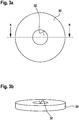
- the sensor element 30 is designed as an annular disc, as in FIG. 3a in a plan view, in FIG. 3b in a perspective view and in Figure 3c shown in a side view.
- the sensor element 30 in this case has a bore 32, which is formed centrally within the sensor element 30, so that ultimately a flat hollow cylinder is formed.
- the sensor element 30 has a first electrode 35 and a second electrode 36, which are applied over the entire area on each side surface of the sensor element 30.
- the first electrode 35 and the second electrode 36 are electrically conductive and connected to a first contact wire 38 and a second contact wire 39.
- the two contact wires 38, 39 are connected via a passage 42, which is formed in the housing 40, with a first contact 44 and a second contact 46, which are located on the outside of the housing 40.
- the signal line 23 can be fixed and thus produce an electrical connection to the evaluation unit 25. Since the sensor element 30 is a piezoelectric sensor element, a deformation of the sensor element 30 generates an electrical voltage between the first electrode 35 and the second electrode 36, which is a measure of the deformation of the sensor element 30.
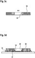
- an adhesive bond 31 is formed between the sensor element 30 and the remainder wall 22, which bonds the sensor element 30 to the remainder of the wall 22.
- the bond 31 is formed so as to cover a part of the wall of the bore 32 and a part of the outside of the sensor element 30, so that an inner meniscus 33 is formed on the inner wall of the bore 32 and also an outer meniscus 34 on the outside of the Sensor element 30, as in 3d figure is shown enlarged again.
- the movement of the residual wall 22 is transferred to the sensor element 30 in a particularly effective manner and thus leads to a higher signal than if only the end face with the second electrode 36 itself were glued to the remaining wall 22.
- the fuel flow within the high-pressure chamber 6 or the high-pressure bore 15 is periodically released or interrupted.
- the liquid column is abruptly decelerated within the pressure chamber 6, resulting in a pressure pulsation within the high-pressure chamber 6, which continues into the high-pressure bore 15.
- This pressure pulsation also affects the deformation of the residual wall 22, wherein the deformation only elastic happens and transmits via the bond 31 to the sensor element 30. From this signal can thus be the movement of the nozzle needle 8, in particular the time at which the nozzle needle 8 rests on the nozzle seat 10, determine and control the injection accordingly.
- the residual wall 22 is pressed by the pressure fluctuations within the high-pressure bore 15 to the outside and deformed accordingly the sensor element 30 so that it is stretched in the region of the first electrode 35 and slightly compressed in the region of the second electrode 36.
- This induces mechanical stresses within the sensor element 30, which would be maximum in the center of the disk-shaped sensor element 30, but are reduced by the formation of the bore 32, since this area is excluded.
- the sensor element 30 can be deformed more strongly by the remaining wall 22 without this being damaged, which in turn makes it possible to make the remaining wall 22 thinner than would be possible with a continuous sensor element 30. This results in a total of a stronger signal on the sensor element 30 without the risk of mechanical damage.
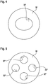
- FIG. 4 shows a further embodiment of the sensor element 30 according to the invention.
- the bore 32 ' is not circular, but has an oval cross-section.
- the mechanical stress within the sensor element 30 can be effectively reduced, in particular, if the deformation of the sensor element 30 does not occur radially symmetrically, but due to the cylindrical shape of the holding body 2 with a preferred direction in which the deformation in the longitudinal direction of the holding body 2 is smaller than tangential to.
- FIG. 5 shows a further embodiment of the sensor element according to the invention, in which case four holes 32 "are formed, which also contribute to a reduction of the mechanical stresses within the sensor element 30, so that even with anisotropic deformation properties of the holder body 2 to an optimal reduction of mechanical stress peaks within the sensor element
Landscapes
- Engineering & Computer Science (AREA)
- Chemical & Material Sciences (AREA)
- Analytical Chemistry (AREA)
- Combustion & Propulsion (AREA)
- Mechanical Engineering (AREA)
- General Engineering & Computer Science (AREA)
- Fuel-Injection Apparatus (AREA)
- Measuring Fluid Pressure (AREA)
Abstract
Description
- Die Erfindung betrifft ein Kraftstoffeinspritzventil, wie es zur Einbringung von Kraftstoff beispielsweise in einen Brennraum einer Brennkraftmaschine Verwendung findet.
- Die Erfindung betrifft ein Kraftstoffeinspritzventil, wie es beispielsweise aus der
DE 10 2015 206 032 A1 bekannt ist. Ein solches Kraftstoffeinspritzventil wird verwendet, um Kraftstoff unter hohem Druck in einen Brennraum einer Brennkraftmaschine einzubringen, wobei der Kraftstoff durch den hohen Druck während der Einspritzung fein zerstäubt wird und dadurch effizient und geräuscharm innerhalb des Brennraums verbrennt. Das Kraftstoffeinspritzventil weist zur Steuerung der Einspritzung eine kolbenförmige Düsennadel auf, welche mit einem Düsensitz zusammenwirkt und dadurch eine oder mehrere Einspritzöffnungen öffnet und schließt. Die Bewegung der Düsennadel wird dabei meistens servo-hydraulisch vorgenommen, wobei die eigentliche Steuerung mittels eines elektromagnetischen oder piezoelektrischen Steuerventils erfolgt. Dabei sind insbesondere der genaue Zeitpunkt und die Dauer der Einspritzung entscheidend für einen sauberen und geräuscharmen Verbrennungsablauf. Für eine optimale Ansteuerung ist es deshalb von großer Wichtigkeit, die tatsächliche Bewegung der Düsennadel zu kennen, um dadurch die Ansteuerung des entsprechenden Steuerventils exakt vornehmen zu können. - Die Einspritzung des Kraftstoffs erfolgt durch einzelne, zeitlich beabstandete Einspritzungen. Das Öffnen und Schließen der Einspritzöffnungen durch die Bewegung der Düsennadel verursacht entsprechend Druckschwankungen innerhalb des Kraftstoffeinspritzventils, die zur Detektion der Nadelbewegung verwendet werden können. Dazu ist aus der
DE 10 2015 206 032 A1 bekannt, einen Sensor zu verwenden, der die Verformung einer Restwand innerhalb des Kraftstoffeinspritzventils durch den Druck des im Inneren anstehenden Kraftstoffs misst und damit die Druckschwankungen innerhalb des Kraftstoffeinspritzventils erfasst. Da die Druckschwankungen mit der Bewegung der Düsennadel korrelieren, lassen sich daraus Rückschlüsse auf die Bewegung der Düsennadel ziehen. - Der hierzu verwendete Sensor ist ein Verformungssensor, der ein piezoelektrisches Sensorelement umfasst, welches durch die Verformung der Restwand mit verformt wird. Die durch die Verformung des Piezoelements verursachte elektrische Spannung kann am Sensorelement abgegriffen und ausgewertet werden. Das Sensorelement ist dazu mit der Restwand flächig verklebt, so dass die Verformung der Restwand auf das Sensorelement unmittelbar übertragen wird. Dabei muss jedoch darauf geachtet werden, dass das piezoelektrische Sensorelement nicht zu stark verformt wird, da die mechanische Stabilität des Piezoelements, insbesondere bei Zugbeanspruchung, nur gering ist. Einerseits darf die Restwand deshalb eine gewisse Dicke nicht unterschreiten, damit die Verformung im tolerierbaren Rahmen bleibt. Andererseits schränkt eine relativ dicke Restwand die Empfindlichkeit ein, was sich negativ auf die Empfindlichkeit der Messung auswirkt.
- Das erfindungsgemäße Kraftstoffeinspritzventil mit den Merkmalen des Patentanspruchs 1 weist demgegenüber den Vorteil auf, dass die Steuerung der Einspritzung exakt möglich ist und ein entsprechend sauberer und geräuscharmer Verbrennungsprozess erreicht werden kann. Dazu weist das Kraftstoffeinspritzventil einen Haltekörper mit einem darin ausgebildeten Hochdruckbereich auf, wobei der Hochdruckbereich in einem Bereich des Haltekörpers durch eine Restwand begrenzt wird, die durch den Druck im Hochdruckbereich nach außen verformbar ist. Weiter ist eine Sensoreinheit zur Detektion einer Verformung der Restwand vorhanden, wobei die Sensoreinheit ein piezoelektrisches, scheibenförmiges Sensorelement umfasst, das mit der Restwand flächig verklebt ist, indem eine Verklebung zwischen dem Sensorelement und der Restwand vorhanden ist. Das Sensorelement weist dabei mindestens eine Bohrung auf.
- Durch die Verformung der Restwand wird das scheibenförmige Sensorelement in gleichem Maße wie die Restwand verformt, so dass eine elektrische Spannung an dem scheibenförmigen piezoelektrischen Sensorelement abgegriffen werden kann. Durch die Ausbildung einer Bohrung kann ein Teil des Bereichs des Sensorelements, das besonders starken mechanischen Verformungen ausgesetzt ist, herausgenommen werden, so dass das Sensorelement insgesamt eine höhere Verformbarkeit aufweist, ohne mechanisch zu versagen. Dies erlaubt es, die Restwand des Kraftstoffeinspritzventils dünner zu gestalten und damit eine stärkere Verformung der Restwand zu erlauben, wodurch sich insgesamt eine höhere Empfindlichkeit der Messung erreichen lässt und die Bewegung der Düsennadel präziser bestimmbar ist.
- In einer ersten vorteilhaften Ausgestaltung ist das Sensorelement als flache Ringscheibe ausgebildet, wobei die Bohrung vorteilhafterweise mittig in dem ringscheibenförmigen Sensorelement ausgebildet ist. Dadurch ergibt sich letztlich ein flacher Hohlzylinder, der mit der Restwand verklebt ist. Da die größte mechanische Zugspannung bei einer flachen Ringscheibe bei einem Aufwölben der Restwand in der Mitte der Ringscheibe auftritt, wird diese durch die Ausbildung der mittigen Bohrung herausgenommen, so dass eine insgesamt stärkere Verformbarkeit des Sensorelements ermöglicht wird, ohne dass es zu einem mechanischen Versagen des piezoelektrischen Sensorelements kommt.
- In einer weiteren vorteilhaften Ausgestaltung ist die Bohrung mit einem ovalen Querschnitt ausgestaltet. Durch den ovalen Querschnitt lässt sich die mechanische Entlastung weiter optimieren, wenn die Verformung des ringscheibenförmigen Sensorelements nicht radialsymmetrisch erfolgt, sondern in Folge der Form des Kraftstoffeinspritzventils mit einer Vorzugsrichtung.
- In einer weiteren vorteilhaften Ausgestaltung erstreckt sich die Verklebung, die zwischen dem Sensorelement und der Restwand ausgebildet ist, bis in die Bohrung hinein und bildet mit der Wand der Bohrung einen inneren Meniskus. Dadurch wird die Verformung der Restwand besonders effektiv auf das Sensorelement übertragen und damit ein besseres Signal erreicht.
- In einer weiteren vorteilhaften Ausgestaltung erstreckt sich die Verklebung bis auf die Außenseite des Sensorelements und bildet somit mit der Außenwand des Sensorelements einen äußeren Meniskus. Auch dies begünstigt die Übertragung der Verformung der Restwand auf das Sensorelement und damit das abgreifbare Sensorsignal am Sensorelement.
- In einer weiteren vorteilhaften Ausgestaltung ist mehr als eine Bohrung im Sensorelement ausgebildet. Dies kann insbesondere dann von Vorteil sein, wenn die Verformung des Sensorelements nicht radial symmetrisch erfolgt, sondern mit einer oder mehreren Vorzugsrichtungen. In diesem Fall kann durch die Bohrungen eine gezielte Entlastung an den belasteten Stellen erreicht werden.
- In einer weiteren vorteilhaften Ausgestaltung ist die Restwand durch eine im Haltekörper ausgebildete und zur Außenseite des Haltekörpers offene Ausnehmung gebildet. Über die Tiefe der Ausnehmung lässt sich die Dicke der Restwand problemlos variieren, und die Ausnehmung bietet darüber hinaus den Vorteil, dass das Sensorelement innerhalb der Ausnehmung gegen mechanische Einflüsse geschützt ist, insbesondere dann, wenn das Sensorelement in der Ausnehmung vollständig Platz findet; auch wird in diesem Fall kein zusätzlicher Bauraum am Kraftstoffeinspritzventil benötigt.
- In einer weiteren vorteilhaften Ausgestaltung umfasst die Sensoreinheit ein Gehäuse, in dem das Sensorelement angeordnet ist. Das Gehäuse bietet sowohl mechanischen Schutz als auch Schutz gegen sonstige Umgebungseinflüsse, wie Flüssigkeit oder Gase.
- Das Sensorelement ist in vorteilhafter Weise mit einer Seitenfläche vollflächig mit der Restwand verklebt, sodass die Bewegung der Restwand unmittelbar an das Sensorelement übertragen wird, ohne dass Bereiche des Sensorelements an der Verformung nicht teilnehmen und dadurch zusätzliche mechanische Spannungen im Sensorelement verursachen.
- Das Sensorelement ist weiterhin in vorteilhafter Weise auf einer Seitenfläche mit einer ersten Elektrode und auf der gegenüberliegenden Seitenfläche mit einer zweiten Elektrode beschichtet. Durch eine elektrische Spannung zwischen den beiden Elektroden, die durch die Verformung des Sensorelements zustande kommt, lässt sich der Grad der Verformung des Sensorelements bestimmen und damit ein entsprechendes Sensorsignal abgreifen, das ein Maß für die Verformung des Sensorelements und damit letztlich für die Verformung der Restwand ist. Dabei bedecken die beiden Elektroden die erste bzw. die zweite Seitenfläche des Sensorelements vorzugsweise vollflächig.
- In der Zeichnung ist ein erfindungsgemäßes Kraftstoffeinspritzventil schematisch dargestellt. Es zeigen:
- Figur 1
- ein erfindungsgemäßes Kraftstoffeinspritzventil im Längsschnitt,
- Figur 2
- eine vergrößerte Darstellung des Kraftstoffeinspritzventils im Bereich der Sensoreinheit,
- Figur 3a
- eine Draufsicht auf das Sensorelement,
- Figur 3b
- eine perspektivische Darstellung des Sensorelements,
- Figur 3c
- einen Querschnitt durch das Sensorelement und
- Figur 3d
- die Verklebung des Sensorelements auf der Restwand, und
- Figur 4
- und
- Figur 5
- jeweils in einer Draufsicht weitere, erfindungsgemäße Sensorelemente.
- In
Figur 1 ist ein erfindungsgemäßes Kraftstoffeinspritzventil im Längsschnitt dargestellt. Das Kraftstoffeinspritzventil 1 weist einen Haltekörper 2 auf, der mit einem Düsenkörper 3 mittels einer Spannmutter 5 flüssigkeitsdicht verspannt ist. Innerhalb des Kraftstoffeinspritzventils 1 ist ein Hochdruckbereich ausgebildet, der einen Druckraum 6 und eine Hochdruckbohrung 15 umfasst, wobei die Hochdruckbohrung 15 innerhalb des Haltekörpers 2 verläuft, und in den in Düsenkörper 3 ausgebildeten Hochdruckraum 6 mündet. Im Hochdruckraum 6 ist eine kolbenförmige Düsennadel 8 längsverschiebbar angeordnet, die mit einem am brennraumseitigen Ende des Kraftstoffeinspritzventils 1 ausgebildeten Düsensitz 10 zusammenwirkt und dadurch eine Verbindung zwischen dem Druckraum 6 und mehreren Einspritzöffnungen 11 öffnet und schließt. Die Längsbewegung der Düsennadel 8 erfolgt dabei in nicht näher dargestellter Weise, beispielsweise servo-hydraulisch oder auch durch direkte Krafteinwirkung, beispielsweise mittels eines Elektromagneten. Hebt die Düsennadel 8 vom Düsensitz 10 ab, so fließt Kraftstoff aus dem Druckraum 6 durch die Einspritzöffnungen 11 und wird durch den hohen Druck, unter dem der Kraftstoff im Druckraum 6 anliegt, beim Austritt aus den Einspritzöffnungen 11 fein zerstäubt. Bewegt sich die Düsennadel 8 wieder in Anlage an den Düsensitz 10, so werden die Einspritzöffnungen 11 vom Druckraum 6 getrennt und die Einspritzung wird unterbrochen. Der durch das Kraftstoffeinspritzventil 1 ausgespritzte Kraftstoff wird in einem Hochdruckspeicher 17 zur Verfügung gestellt, der beispielsweise durch eine Kraftstoffhochdruckpumpe mit verdichtetem Kraftstoff gespeist ist. Der Kraftstoff wird aus dem Kraftstoffhochdruckspeicher 17 über eine Hochdruckleitung 16 in die Hochdruckbohrung 15 geleitet und gelangt von dort in den Hochdruckraum 6. - Im Haltekörper 2 ist eine Ausnehmung 18 ausgebildet, die zur Außenseite des Haltekörpers 2 offen ist und in der eine Sensoreinheit 20 angeordnet ist. Die Sensoreinheit 20 ist über eine Signalleitung 23 mit einer Auswerteeinheit 25 verbunden, sodass ein elektrisches Signal, das von der Sensoreinheit 20 geliefert wird, durch die Auswerteeinheit 25, die beispielsweise als Steuergerät ausgebildet ist, ausgewertet werden kann. Durch die Ausnehmung 18 verbleibt zwischen der Hochdruckbohrung 15 und der Ausnehmung 18 eine Restwand 22, die deutlich dünner ist als die sonstige Wandung, die den Hochdruckkanal 15 begrenzt, sodass durch den Kraftstoffdruck innerhalb der Hochdruckbohrung 15 eine messbare Verformung der Restwand 22 stattfindet.
-
Figur 2 zeigt eine vergrößerte Darstellung der Sensoreinheit 20 und von Teilen des Haltekörpers 2 im Längsschnitt. Die Sensoreinheit 20 umfasst ein Sensorelement 30, das scheibenförmig ausgebildet ist und aus einem piezoelektrischen Material besteht. Das Sensorelement 30 ist dabei als Ringscheibe ausgebildet, wie inFigur 3a in einer Draufsicht, inFigur 3b in einer perspektivischen Darstellung und inFigur 3c in einer Seitenansicht dargestellt. Das Sensorelement 30 weist dabei eine Bohrung 32 auf, die mittig innerhalb des Sensorelements 30 ausgebildet ist, sodass letztlich ein flacher Hohlzylinder gebildet wird. - Wieder bezugnehmend auf
Figur 2 ist hier die Einbausituation des Sensorelements 30 dargestellt. Das Sensorelement 30 weist eine erste Elektrode 35 und eine zweite Elektrode 36 auf, die auf jeweils einer Seitenfläche des Sensorelements 30 vollflächig aufgebracht sind. Die erste Elektrode 35 und die zweite Elektrode 36 sind dabei elektrisch leitend und mit einem ersten Kontaktdraht 38 bzw. einem zweiten Kontaktdraht 39 verbunden. Die beiden Kontaktdrähte 38, 39 sind über eine Durchführung 42, die im Gehäuse 40 ausgebildet ist, mit einem ersten Kontakt 44 bzw. einem zweiten Kontakt 46 verbunden, die sich an der Außenseite des Gehäuses 40 befinden. An diesen beiden Kontakten 44, 45 lässt sich die Signalleitung 23 befestigen und damit eine elektrische Verbindung zur Auswerteeinheit 25 herstellen. Da das Sensorelement 30 ein piezoelektrisches Sensorelement ist, wird durch eine Verformung des Sensorelements 30 eine elektrische Spannung zwischen der ersten Elektrode 35 und der zweiten Elektrode 36 erzeugt, die ein Maß für die Verformung des Sensorelements 30 ist. - Um die Verformung der Restwand 22 auf das Sensorelement 30 möglichst verlustfrei zu übertragen, ist zwischen dem Sensorelement 30 und der Restwand 22 eine Verklebung 31 ausgebildet, die das Sensorelement 30 vollflächig mit der Restwand 22 verbindet. Dabei ist die Verklebung 31 so ausgebildet, dass sie einen Teil der Wandung der Bohrung 32 und einen Teil der Außenseite des Sensorelements 30 bedeckt, sodass ein innerer Meniskus 33 an der Innenwand der Bohrung 32 gebildet wird und ebenso ein äußerer Meniskus 34 an der Außenseite des Sensorelements 30, wie dies in
Figur 3d nochmals vergrößert dargestellt ist. Durch die Ausbildung der Menisken 33, 34 wird die Bewegung der Restwand 22 besonders effektiv auf das Sensorelement 30 übertragen und führt somit zu einem höheren Signal als wenn nur die Stirnseite mit der zweiten Elektrode 36 selbst mit der Restwand 22 verklebt wäre. - Durch die Bewegung der Düsennadel wird der Kraftstofffluss innerhalb des Hochdruckraums 6 bzw. der Hochdruckbohrung 15 periodisch freigegeben bzw. unterbrochen. Insbesondere beim Schließen der Düsennadel 8, d. h. beim Aufsetzen auf den Düsensitz 10, wird die Flüssigkeitssäule innerhalb des Druckraums 6 abrupt abgebremst, was zu einer Druckpulsation innerhalb des Hochdruckraums 6 führt, die sich bis in die Hochdruckbohrung 15 fortsetzt. Diese Druckpulsation wirkt sich auch auf die Verformung der Restwand 22 aus, wobei die Verformung ausschließlich elastisch geschieht und sich über die Verklebung 31 auf das Sensorelement 30 überträgt. Aus diesem Signal lässt sich somit die Bewegung der Düsennadel 8, insbesondere der Zeitpunkt, zu dem die Düsennadel 8 auf dem Düsensitz 10 aufliegt, bestimmen und entsprechend die Einspritzung steuern.
- Die Restwand 22 wird durch die Druckschwankungen innerhalb der Hochdruckbohrung 15 nach außen gedrückt und verformt entsprechend das Sensorelement 30, sodass dieses im Bereich der ersten Elektrode 35 gedehnt und im Bereich der zweiten Elektrode 36 etwas gestaucht wird. Dies induziert mechanische Spannungen innerhalb des Sensorelements 30, die besonders in der Mitte des scheibenförmigen Sensorelements 30 maximal wären, jedoch durch die Ausbildung der Bohrung 32 vermindert sind, da dieser Bereich ausgenommen wird. Dadurch kann das Sensorelement 30 stärker durch die Restwand 22 verformt werden ohne dass dieses Schaden nimmt, was es wiederum ermöglicht, die Restwand 22 dünner zu gestalten als dies bei einem durchgängigen Sensorelement 30 möglich wäre. Damit ergibt sich insgesamt ein stärkeres Signal am Sensorelement 30, ohne dass die Gefahr von mechanischen Schäden besteht.
-
Figur 4 zeigt ein weiteres Ausführungsbeispiel des erfindungsgemäßen Sensorelements 30. Dabei ist die Bohrung 32' nicht kreisrund ausgeführt, sondern weist einen ovalen Querschnitt auf. Dadurch lässt sich die mechanische Spannung innerhalb des Sensorelements 30 insbesondere dann effektiv vermindern, wenn die Verformung des Sensorelements 30 nicht radialsymmetrisch geschieht, sondern in Folge der Zylinderform des Haltekörpers 2 mit einer Vorzugsrichtung, bei der die Verformung in Längsrichtung des Haltekörpers 2 kleiner ist als tangential dazu. -
Figur 5 zeigt ein weiteres Ausführungsbeispiel des erfindungsgemäßen Sensorelements, wobei hier vier Bohrungen 32" ausgebildet sind, die ebenfalls zu einer Verminderung der mechanischen Spannungen innerhalb des Sensorelements 30 beitragen, sodass es auch bei anisotropen Verformungseigenschaften des Haltekörpers 2 zu einer optimalen Verminderung von mechanischen Spannungsspitzen innerhalb des Sensorelements 30 kommen kann. Es sind auch andere Formen von Bohrungen oder eine größere oder kleinere Anzahl von Bohrungen denkbar, je nachdem, welchen mechanischen Verformungen das Sensorelement 30 in seiner konkreten Einbausituation genau ausgesetzt ist.
Claims (13)
- Kraftstoffeinspritzventil (1) mit einem Haltekörper (2) und einem darin ausgebildeten Hochdruckbereich (15; 16), wobei der Hochdruckbereich (15; 16) in einem Bereich des Haltekörpers (2) durch eine Restwand (22) begrenzt wird, die durch den Druck im Hochdruckbereich (15; 16) nach außen verformbar ist, und mit einer Sensoreinheit (20) zur Detektion einer Verformung der Restwand (22), wobei die Sensoreinheit (20) ein piezoelektrisches, scheibenförmiges Sensorelement (30) umfasst, das mit der Restwand (22) flächig verklebt ist, indem eine Verklebung (31) zwischen dem Sensorelement (30) und der Restwand (22) vorhanden ist, dadurch gekennzeichnet, dass das Sensorelement (30) mindestens eine Bohrung (32) aufweist.
- Kraftstoffeinspritzventil nach Anspruch 1, dadurch gekennzeichnet, dass das Sensorelement (30) als flache Ringscheibe ausgebildet ist.
- Kraftstoffeinspritzventil nach Anspruch 2, dadurch gekennzeichnet, dass die Bohrung (32) mittig in dem ringscheibenförmigen Sensorelement (30) ausgebildet ist.
- Kraftstoffeinspritzventil nach Anspruch 1, dadurch gekennzeichnet, dass die Bohrung (32') einen ovalen Querschnitt aufweist.
- Kraftstoffeinspritzventil nach Anspruch 1, dadurch gekennzeichnet, dass sich die Verklebung (31) bis in die Bohrung (32) erstreckt und mit der Wand der Bohrung (32) einen inneren Meniskus (33) bildet.
- Kraftstoffeinspritzventil nach Anspruch 1 oder 5, dadurch gekennzeichnet, dass sich die Verklebung (31) bis auf die Außenseite des Sensorelements (30) erstreckt und mit der Außenwand des Sensorelements (30) einen äußeren Meniskus (34) bildet.
- Kraftstoffeinspritzventil nach Anspruch 1 oder 5, dadurch gekennzeichnet, dass mehr als eine Bohrung (32) im Sensorelement (30") ausgebildet ist.
- Kraftstoffeinspritzventil nach einem der Ansprüche 1 bis 7, dadurch gekennzeichnet, dass die Restwand (22) durch eine im Haltekörper (2) ausgebildete und zur Außenseite des Haltekörpers offene Ausnehmung (18) gebildet wird.
- Kraftstoffeinspritzventil nach einem der Ansprüche 1 bis 8, dadurch gekennzeichnet, dass die Sensoreinheit ein Gehäuse (40) umfasst, in dem das Sensorelement (30) angeordnet ist.
- Kraftstoffeinspritzventil nach einem der Ansprüche 1 bis 9, dadurch gekennzeichnet, dass das Sensorelement (30) mit einer Seitenfläche vollflächig mit der Restwand (22) verklebt ist.
- Kraftstoffeinspritzventil nach Anspruch 10, dadurch gekennzeichnet, dass das Sensorelement (30) auf einer Seitenfläche eine erste Elektrode (35) und auf der gegenüberliegenden Seitenfläche eine zweite Elektrode (36) aufweist.
- Kraftstoffeinspritzventil nach Anspruch 11, dadurch gekennzeichnet, dass die erste Elektrode (35) die erste Seitenfläche des Sensorelements (30) vollflächig bedeckt.
- Kraftstoffeinspritzventil nach Anspruch 11 oder 12, dadurch gekennzeichnet, dass die zweite Elektrode (36) die zweite Seitenfläche des Sensorelements (30) vollflächig bedeckt.
Applications Claiming Priority (1)
| Application Number | Priority Date | Filing Date | Title |
|---|---|---|---|
| DE102016202842.1A DE102016202842A1 (de) | 2016-02-24 | 2016-02-24 | Kraftstoffeinspritzventil |
Publications (1)
| Publication Number | Publication Date |
|---|---|
| EP3211209A1 true EP3211209A1 (de) | 2017-08-30 |
Family
ID=57995106
Family Applications (1)
| Application Number | Title | Priority Date | Filing Date |
|---|---|---|---|
| EP17155167.4A Withdrawn EP3211209A1 (de) | 2016-02-24 | 2017-02-08 | Kraftstoffeinspritzventil |
Country Status (2)
| Country | Link |
|---|---|
| EP (1) | EP3211209A1 (de) |
| DE (1) | DE102016202842A1 (de) |
Citations (5)
| Publication number | Priority date | Publication date | Assignee | Title |
|---|---|---|---|---|
| US4429570A (en) * | 1981-09-25 | 1984-02-07 | Essex Group, Inc. | Injection timing transducer |
| DE19622651A1 (de) * | 1995-06-09 | 1996-12-12 | Unisia Jecs Corp | Zylinderdruck-Erfassungsvorrichtung |
| WO1999032783A1 (en) * | 1997-12-22 | 1999-07-01 | Stanadyne Automotive Corp. | Duration control of common rail fuel injector |
| WO2009019663A2 (en) * | 2007-08-07 | 2009-02-12 | Delphi Technologies, Inc. | Fuel injector and method for controlling fuel injectors |
| DE102015206032A1 (de) | 2015-04-02 | 2016-10-06 | Robert Bosch Gmbh | Kraftstoffinjektor und Verfahren zum Herstellen eines Kraftstoffinjektors |
-
2016
- 2016-02-24 DE DE102016202842.1A patent/DE102016202842A1/de not_active Withdrawn
-
2017
- 2017-02-08 EP EP17155167.4A patent/EP3211209A1/de not_active Withdrawn
Patent Citations (5)
| Publication number | Priority date | Publication date | Assignee | Title |
|---|---|---|---|---|
| US4429570A (en) * | 1981-09-25 | 1984-02-07 | Essex Group, Inc. | Injection timing transducer |
| DE19622651A1 (de) * | 1995-06-09 | 1996-12-12 | Unisia Jecs Corp | Zylinderdruck-Erfassungsvorrichtung |
| WO1999032783A1 (en) * | 1997-12-22 | 1999-07-01 | Stanadyne Automotive Corp. | Duration control of common rail fuel injector |
| WO2009019663A2 (en) * | 2007-08-07 | 2009-02-12 | Delphi Technologies, Inc. | Fuel injector and method for controlling fuel injectors |
| DE102015206032A1 (de) | 2015-04-02 | 2016-10-06 | Robert Bosch Gmbh | Kraftstoffinjektor und Verfahren zum Herstellen eines Kraftstoffinjektors |
Also Published As
| Publication number | Publication date |
|---|---|
| DE102016202842A1 (de) | 2017-08-24 |
Similar Documents
| Publication | Publication Date | Title |
|---|---|---|
| EP2901004A1 (de) | Einspritzventil | |
| EP3286428B1 (de) | Kraftstoffinjektor | |
| WO2011069717A1 (de) | Kraftstoffeinspritzvorrichtung mit nadelpositionsbestimmung | |
| EP0823959A1 (de) | Kraftstoffeinspritzventil für brennkraftmaschinen | |
| EP1309791B1 (de) | Brennstoffeinspritzventil | |
| WO2017102208A1 (de) | Kraftstoffeinspritzdüse | |
| EP1117922B1 (de) | Common-rail-injektor | |
| DE102008000301A1 (de) | Injektor | |
| EP3026254B1 (de) | Injektor mit einem Sensor zur Aufnahme eines Druckverlaufs | |
| EP3001024B1 (de) | Kraftstoffinjektor und verwendung eines kraftstoffinjektors | |
| EP3211209A1 (de) | Kraftstoffeinspritzventil | |
| EP0179278A2 (de) | Drucksensor | |
| WO2005095789A1 (de) | Einrichtung zum einspritzen von kraftstoff in den brennraum einer brennkraftmaschine mit einem nadelhubsensor | |
| EP2864623B1 (de) | Einspritzventil | |
| WO2002092996A1 (de) | Ventil zum steuern von flüssigkeiten | |
| EP3111079B1 (de) | Kraftstoffinjektor | |
| EP3222844B1 (de) | Kraftstoffinjektor | |
| EP3034854B1 (de) | Kraftstoffinjektor und verfahren zur erkennung zumindest des schliesszeitpunkts eines einspritzglieds | |
| DE102017214845A1 (de) | Radialkolbenpumpe | |
| DE102004015045A1 (de) | Verfahren zur Ermittlung der Position eines beweglichen Verschlusselementes eines Einspritzventils | |
| DE102016203822A1 (de) | Kraftstoffeinspritzventil | |
| EP2653712A1 (de) | Kraftstoffinjektor mit Magnetventil | |
| DE102006032743A1 (de) | Aktor zum Hubantrieb eines Stellglieds | |
| DE102020215217A1 (de) | Brennstoffeinspritzventil | |
| DE102021208503A1 (de) | Gasdosierventil für gasförmigen Brennstoff |
Legal Events
| Date | Code | Title | Description |
|---|---|---|---|
| PUAI | Public reference made under article 153(3) epc to a published international application that has entered the european phase |
Free format text: ORIGINAL CODE: 0009012 |
|
| AK | Designated contracting states |
Kind code of ref document: A1 Designated state(s): AL AT BE BG CH CY CZ DE DK EE ES FI FR GB GR HR HU IE IS IT LI LT LU LV MC MK MT NL NO PL PT RO RS SE SI SK SM TR |
|
| AX | Request for extension of the european patent |
Extension state: BA ME |
|
| 17P | Request for examination filed |
Effective date: 20180228 |
|
| RBV | Designated contracting states (corrected) |
Designated state(s): AL AT BE BG CH CY CZ DE DK EE ES FI FR GB GR HR HU IE IS IT LI LT LU LV MC MK MT NL NO PL PT RO RS SE SI SK SM TR |
|
| 17Q | First examination report despatched |
Effective date: 20180903 |
|
| RIC1 | Information provided on ipc code assigned before grant |
Ipc: F02M 57/00 20060101AFI20180824BHEP |
|
| STAA | Information on the status of an ep patent application or granted ep patent |
Free format text: STATUS: THE APPLICATION IS DEEMED TO BE WITHDRAWN |
|
| 18D | Application deemed to be withdrawn |
Effective date: 20190314 |