EP3211154B1 - Manufacturing process of concrete towers for wind turbines - Google Patents
Manufacturing process of concrete towers for wind turbines Download PDFInfo
- Publication number
- EP3211154B1 EP3211154B1 EP16382082.2A EP16382082A EP3211154B1 EP 3211154 B1 EP3211154 B1 EP 3211154B1 EP 16382082 A EP16382082 A EP 16382082A EP 3211154 B1 EP3211154 B1 EP 3211154B1
- Authority
- EP
- European Patent Office
- Prior art keywords
- section
- stage
- cylindrical section
- manufacturing process
- formwork system
- Prior art date
- Legal status (The legal status is an assumption and is not a legal conclusion. Google has not performed a legal analysis and makes no representation as to the accuracy of the status listed.)
- Active
Links
- 238000004519 manufacturing process Methods 0.000 title claims description 37
- 238000009415 formwork Methods 0.000 claims description 97
- 230000009194 climbing Effects 0.000 claims description 70
- 238000010276 construction Methods 0.000 claims description 52
- 230000007704 transition Effects 0.000 claims description 46
- 238000011065 in-situ storage Methods 0.000 claims description 28
- 238000000034 method Methods 0.000 claims description 9
- 230000006978 adaptation Effects 0.000 claims description 8
- 230000008569 process Effects 0.000 claims description 8
- 238000009434 installation Methods 0.000 claims description 4
- 230000004048 modification Effects 0.000 claims description 3
- 238000012986 modification Methods 0.000 claims description 3
- 239000000463 material Substances 0.000 description 5
- 238000010586 diagram Methods 0.000 description 4
- 230000008859 change Effects 0.000 description 2
- 230000003247 decreasing effect Effects 0.000 description 2
- 229910000831 Steel Inorganic materials 0.000 description 1
- 230000007423 decrease Effects 0.000 description 1
- 238000006073 displacement reaction Methods 0.000 description 1
- 230000000694 effects Effects 0.000 description 1
- 239000010959 steel Substances 0.000 description 1
Images
Classifications
-
- E—FIXED CONSTRUCTIONS
- E04—BUILDING
- E04H—BUILDINGS OR LIKE STRUCTURES FOR PARTICULAR PURPOSES; SWIMMING OR SPLASH BATHS OR POOLS; MASTS; FENCING; TENTS OR CANOPIES, IN GENERAL
- E04H12/00—Towers; Masts or poles; Chimney stacks; Water-towers; Methods of erecting such structures
- E04H12/34—Arrangements for erecting or lowering towers, masts, poles, chimney stacks, or the like
- E04H12/342—Arrangements for stacking tower sections on top of each other
-
- B—PERFORMING OPERATIONS; TRANSPORTING
- B66—HOISTING; LIFTING; HAULING
- B66C—CRANES; LOAD-ENGAGING ELEMENTS OR DEVICES FOR CRANES, CAPSTANS, WINCHES, OR TACKLES
- B66C23/00—Cranes comprising essentially a beam, boom, or triangular structure acting as a cantilever and mounted for translatory of swinging movements in vertical or horizontal planes or a combination of such movements, e.g. jib-cranes, derricks, tower cranes
- B66C23/18—Cranes comprising essentially a beam, boom, or triangular structure acting as a cantilever and mounted for translatory of swinging movements in vertical or horizontal planes or a combination of such movements, e.g. jib-cranes, derricks, tower cranes specially adapted for use in particular purposes
- B66C23/20—Cranes comprising essentially a beam, boom, or triangular structure acting as a cantilever and mounted for translatory of swinging movements in vertical or horizontal planes or a combination of such movements, e.g. jib-cranes, derricks, tower cranes specially adapted for use in particular purposes with supporting couples provided by walls of buildings or like structures
- B66C23/207—Cranes comprising essentially a beam, boom, or triangular structure acting as a cantilever and mounted for translatory of swinging movements in vertical or horizontal planes or a combination of such movements, e.g. jib-cranes, derricks, tower cranes specially adapted for use in particular purposes with supporting couples provided by walls of buildings or like structures with supporting couples provided by wind turbines
-
- E—FIXED CONSTRUCTIONS
- E04—BUILDING
- E04H—BUILDINGS OR LIKE STRUCTURES FOR PARTICULAR PURPOSES; SWIMMING OR SPLASH BATHS OR POOLS; MASTS; FENCING; TENTS OR CANOPIES, IN GENERAL
- E04H12/00—Towers; Masts or poles; Chimney stacks; Water-towers; Methods of erecting such structures
- E04H12/02—Structures made of specified materials
- E04H12/12—Structures made of specified materials of concrete or other stone-like material, with or without internal or external reinforcements, e.g. with metal coverings, with permanent form elements
-
- E—FIXED CONSTRUCTIONS
- E04—BUILDING
- E04H—BUILDINGS OR LIKE STRUCTURES FOR PARTICULAR PURPOSES; SWIMMING OR SPLASH BATHS OR POOLS; MASTS; FENCING; TENTS OR CANOPIES, IN GENERAL
- E04H12/00—Towers; Masts or poles; Chimney stacks; Water-towers; Methods of erecting such structures
- E04H12/16—Prestressed structures
-
- E—FIXED CONSTRUCTIONS
- E04—BUILDING
- E04H—BUILDINGS OR LIKE STRUCTURES FOR PARTICULAR PURPOSES; SWIMMING OR SPLASH BATHS OR POOLS; MASTS; FENCING; TENTS OR CANOPIES, IN GENERAL
- E04H12/00—Towers; Masts or poles; Chimney stacks; Water-towers; Methods of erecting such structures
- E04H12/34—Arrangements for erecting or lowering towers, masts, poles, chimney stacks, or the like
- E04H12/341—Arrangements for casting in situ concrete towers or the like
-
- F—MECHANICAL ENGINEERING; LIGHTING; HEATING; WEAPONS; BLASTING
- F03—MACHINES OR ENGINES FOR LIQUIDS; WIND, SPRING, OR WEIGHT MOTORS; PRODUCING MECHANICAL POWER OR A REACTIVE PROPULSIVE THRUST, NOT OTHERWISE PROVIDED FOR
- F03D—WIND MOTORS
- F03D13/00—Assembly, mounting or commissioning of wind motors; Arrangements specially adapted for transporting wind motor components
- F03D13/10—Assembly of wind motors; Arrangements for erecting wind motors
-
- E—FIXED CONSTRUCTIONS
- E04—BUILDING
- E04G—SCAFFOLDING; FORMS; SHUTTERING; BUILDING IMPLEMENTS OR AIDS, OR THEIR USE; HANDLING BUILDING MATERIALS ON THE SITE; REPAIRING, BREAKING-UP OR OTHER WORK ON EXISTING BUILDINGS
- E04G11/00—Forms, shutterings, or falsework for making walls, floors, ceilings, or roofs
- E04G11/06—Forms, shutterings, or falsework for making walls, floors, ceilings, or roofs for walls, e.g. curved end panels for wall shutterings; filler elements for wall shutterings; shutterings for vertical ducts
- E04G11/20—Movable forms; Movable forms for moulding cylindrical, conical or hyperbolical structures; Templates serving as forms for positioning blocks or the like
- E04G11/28—Climbing forms, i.e. forms which are not in contact with the poured concrete during lifting from layer to layer and which are anchored in the hardened concrete
-
- E—FIXED CONSTRUCTIONS
- E04—BUILDING
- E04H—BUILDINGS OR LIKE STRUCTURES FOR PARTICULAR PURPOSES; SWIMMING OR SPLASH BATHS OR POOLS; MASTS; FENCING; TENTS OR CANOPIES, IN GENERAL
- E04H12/00—Towers; Masts or poles; Chimney stacks; Water-towers; Methods of erecting such structures
- E04H2012/006—Structures with truss-like sections combined with tubular-like sections
-
- F—MECHANICAL ENGINEERING; LIGHTING; HEATING; WEAPONS; BLASTING
- F05—INDEXING SCHEMES RELATING TO ENGINES OR PUMPS IN VARIOUS SUBCLASSES OF CLASSES F01-F04
- F05B—INDEXING SCHEME RELATING TO WIND, SPRING, WEIGHT, INERTIA OR LIKE MOTORS, TO MACHINES OR ENGINES FOR LIQUIDS COVERED BY SUBCLASSES F03B, F03D AND F03G
- F05B2230/00—Manufacture
- F05B2230/60—Assembly methods
- F05B2230/61—Assembly methods using auxiliary equipment for lifting or holding
-
- F—MECHANICAL ENGINEERING; LIGHTING; HEATING; WEAPONS; BLASTING
- F05—INDEXING SCHEMES RELATING TO ENGINES OR PUMPS IN VARIOUS SUBCLASSES OF CLASSES F01-F04
- F05B—INDEXING SCHEME RELATING TO WIND, SPRING, WEIGHT, INERTIA OR LIKE MOTORS, TO MACHINES OR ENGINES FOR LIQUIDS COVERED BY SUBCLASSES F03B, F03D AND F03G
- F05B2240/00—Components
- F05B2240/90—Mounting on supporting structures or systems
- F05B2240/91—Mounting on supporting structures or systems on a stationary structure
- F05B2240/912—Mounting on supporting structures or systems on a stationary structure on a tower
-
- Y—GENERAL TAGGING OF NEW TECHNOLOGICAL DEVELOPMENTS; GENERAL TAGGING OF CROSS-SECTIONAL TECHNOLOGIES SPANNING OVER SEVERAL SECTIONS OF THE IPC; TECHNICAL SUBJECTS COVERED BY FORMER USPC CROSS-REFERENCE ART COLLECTIONS [XRACs] AND DIGESTS
- Y02—TECHNOLOGIES OR APPLICATIONS FOR MITIGATION OR ADAPTATION AGAINST CLIMATE CHANGE
- Y02E—REDUCTION OF GREENHOUSE GAS [GHG] EMISSIONS, RELATED TO ENERGY GENERATION, TRANSMISSION OR DISTRIBUTION
- Y02E10/00—Energy generation through renewable energy sources
- Y02E10/70—Wind energy
- Y02E10/72—Wind turbines with rotation axis in wind direction
-
- Y—GENERAL TAGGING OF NEW TECHNOLOGICAL DEVELOPMENTS; GENERAL TAGGING OF CROSS-SECTIONAL TECHNOLOGIES SPANNING OVER SEVERAL SECTIONS OF THE IPC; TECHNICAL SUBJECTS COVERED BY FORMER USPC CROSS-REFERENCE ART COLLECTIONS [XRACs] AND DIGESTS
- Y02—TECHNOLOGIES OR APPLICATIONS FOR MITIGATION OR ADAPTATION AGAINST CLIMATE CHANGE
- Y02E—REDUCTION OF GREENHOUSE GAS [GHG] EMISSIONS, RELATED TO ENERGY GENERATION, TRANSMISSION OR DISTRIBUTION
- Y02E10/00—Energy generation through renewable energy sources
- Y02E10/70—Wind energy
- Y02E10/728—Onshore wind turbines
-
- Y—GENERAL TAGGING OF NEW TECHNOLOGICAL DEVELOPMENTS; GENERAL TAGGING OF CROSS-SECTIONAL TECHNOLOGIES SPANNING OVER SEVERAL SECTIONS OF THE IPC; TECHNICAL SUBJECTS COVERED BY FORMER USPC CROSS-REFERENCE ART COLLECTIONS [XRACs] AND DIGESTS
- Y02—TECHNOLOGIES OR APPLICATIONS FOR MITIGATION OR ADAPTATION AGAINST CLIMATE CHANGE
- Y02P—CLIMATE CHANGE MITIGATION TECHNOLOGIES IN THE PRODUCTION OR PROCESSING OF GOODS
- Y02P70/00—Climate change mitigation technologies in the production process for final industrial or consumer products
- Y02P70/50—Manufacturing or production processes characterised by the final manufactured product
Definitions
- the present invention relates to a manufacturing process of concrete towers for wind turbines which enables executing a concrete tower design manufactured in situ by means of climbing formwork which reduces the execution time of the tower.
- tower geometry it is typically preferred that it has a section that decreases with height, with truncated cones being frequent. This involves modifying the geometry of the internal and external formworks with high frequency, when the construction process is in situ by means of climbing formworks, increasing the number of operations to perform and slowing down the construction time.
- Document EP1227204A1 discloses a manufacturing process of concrete towers for wind turbines according to the preamble of claim 1 and document DE102011053017A1 discloses a concrete tower for wind turbines comprising at least two sections of non-constant outer diameter, a first section and a second section, where the second section is higher than the first section.
- the present invention relates to a manufacturing process according to claim 1 of concrete towers for wind turbines and to a concrete tower for wind turbines formed by a reduced number of different cylindrical sections which enables achieving a compromise between the speed of tower construction and the overuse of materials.
- each different cylindrical section may require a manoeuvre to change formwork system, the fewer number of different cylindrical sections that the tower has, the faster its execution will be but the greater the cost of materials will be. Whilst with a greater number of sections the process would involve a longer construction time although material consumption would be optimized.
- the tower of the present invention achieves said commitment so that the assembly time and resources and the use of materials are optimized overall.
- the proposed process consists of manufacturing in situ the concrete tower using a first climbing formwork system to form cylindrical sections, where the number of operations to change the formwork system is minimized or even eliminated, since the maximum variation in diameter between the larger diameter of a first cylindrical section of concrete tower and the smaller diameter of a second cylindrical section of concrete which will be described below, is delimited so that it is not necessary to use a second climbing formwork system.
- the manufacturing process of concrete towers for wind turbines according to claim 1 comprises:
- the execution stage of the second cylindrical section of concrete tower is carried out so that an inner diameter of the second cylindrical section is smaller than an inner diameter of the first cylindrical section.
- the execution stage of the first cylindrical section and/or the execution stage of the second cylindrical section comprises a modification sub-stage of an inner formwork of the first climbing formwork system and/or of the second climbing formwork system respectively, preferably so that the thickness of the first cylindrical section and/or the second cylindrical section are decreasing in height, reducing the weight of the tower.
- the manufacturing process of concrete towers comprises a construction stage of a top section of concrete tower, preferably on the upper cylindrical section of concrete tower, which allows that the top section of concrete tower and the upper cylindrical section of concrete tower are continuously executed, without horizontal or vertical joints.
- the manufacturing process comprises an assembly stage of the first climbing formwork system on a section of concrete tower manufactured prior to the execution stage of the first cylindrical section of concrete tower.
- the construction stage of the intermediate transition section can be carried out on the first cylindrical section, preferably by means of an adaptation stage of the first climbing formwork system, for the in situ construction of the intermediate transition section, which allows that the intermediate transition section and the first cylindrical section are executed continuously, without horizontal or vertical joints.
- the manufacturing process comprises, after the construction stage of the intermediate transition section and before the execution stage of the second cylindrical section, an adaptation stage of an outer formwork of the first climbing formwork system to the outer diameter of the second cylindrical section.
- an adaptation stage of an outer formwork of the first climbing formwork system to the outer diameter of the second cylindrical section.
- the execution stage of the first cylindrical section and/or the execution stage of the second cylindrical section comprise the following sub-stages:
- both the first cylindrical section and the second cylindrical section are continuously executed, without horizontal or vertical joints.
- a concrete tower for wind turbines comprising at least two sections of constant outer diameter, a first cylindrical section and a second cylindrical section, where the second cylindrical section is higher than the first cylindrical section and where an outer diameter of the second cylindrical section is smaller than an outer diameter of the first cylindrical section, where the first cylindrical section and the second cylindrical section are both intended to be executed in situ by means of a first climbing formwork system.
- the concrete tower also comprises an intermediate transition section disposed between the first cylindrical section and the second cylindrical section, where, preferably said intermediate transition section is a section which is intended to be executed in situ or a prefabricated concrete element.
- the concrete tower also comprises a top section disposed on the second cylindrical section or on an upper cylindrical section, where, preferably said top section is a section which is intended to be executed in situ or a prefabricated concrete element.
- the concrete tower also comprises a lower section of concrete tower which is lower than the first cylindrical section, where said lower section of concrete tower has an outer diameter larger than the outer diameter of the first cylindrical section and where the first cylindrical section is intended to be executed on the lower section of concrete tower.
- the manufacturing process of concrete towers for wind turbines comprises:
- the manufacturing process also comprises a construction stage of an intermediate transition section (3) before the execution stage of the second cylindrical section (2) of concrete tower, where the construction stages of the intermediate transition section (3) and execution stage of the second cylindrical section (2) of concrete tower are repeated until the second cylindrical section (2) is an upper cylindrical section of concrete tower.
- a top section (7) of concrete tower shall be constructed as shall be explained below.
- the manufacturing process comprises an assembly stage of the first climbing formwork system (4) on a lower section (10) of concrete tower manufactured prior to the execution stage of the first cylindrical section (1) of concrete tower, where, preferably, the lower section (10) of concrete tower is manufactured in situ on foundations (11) of the concrete tower.
- the construction stage of the intermediate transition section (3) is carried out on the first cylindrical section (1).
- the intermediate transition section (3) and the first cylindrical section (1) are continuously executed, without horizontal or vertical joints.
- This construction stage of the intermediate transition section (3) on the first cylindrical section (1) can be carried out in two ways:
- the construction stage of the intermediate transition section (3) comprises a manufacturing stage of the intermediate transition section (3) in an area close to a base of the concrete tower and an installation stage of the intermediate transition section (3) manufactured in an area close to a base of the concrete tower, on the first cylindrical section (1), preferably using a crane (6) coupled to the first climbing formwork system (4).
- a crane (6) coupled to the first climbing formwork system (4).
- the manufacturing process of concrete towers for wind turbines comprises, after the construction stage of the intermediate transition section (3) and before the execution stage of the second cylindrical section (2), an adaptation stage of an outer formwork of the first climbing formwork system (4) to the outer diameter of the second cylindrical section (2) and preferably also an adaptation stage of an inner formwork of the first climbing formwork system (4) to an inner diameter of the second cylindrical section (2).
- the construction stage of the top section (7) of concrete tower performed after the execution stage of the upper section of concrete tower is carried out on the upper cylindrical section of concrete tower.
- the upper cylindrical section and the top section (7) are continuously executed, without horizontal or vertical joints.
- This construction stage of the top section (7) on the upper cylindrical section can be carried out:
- the construction stage of the top section (7) of concrete tower comprises a manufacturing stage of the top section (7) in an area close to a base of the concrete tower.
- this construction stage of the top section (7) comprises an installation stage of the top section (7) manufactured in an area close to a base of the concrete tower, on the upper cylindrical section, preferably using a crane (6) coupled to the first climbing formwork system (4). In this way, it dispenses with the concrete setting time as the top section (7) is already prefabricated once installed on the upper cylindrical section.
- the execution stage of the first cylindrical section (1) and/or the execution stage of the second cylindrical section (2) comprise the following sub-stages:
- the first climbing formwork system (4) and/or the second climbing formwork system (5) comprise a set of hydraulic jacks each one of which has two climbing heads, an upper climbing head disposed on a moving part of the hydraulic jack and a lower climbing head disposed on a fixed part of the hydraulic jack.
- Each climbing head comprises a system of pins which makes it possible to be temporarily fixed to a mast which is vertically disposed on the tower surface as a guide or to the tower itself, where the upper climbing head of each hydraulic jack is also solidly joined to a main platform of the first formwork system or of the second formwork system.
- the vertical displacement of the first formwork system or of the second formwork system is achieved by means of the actuation of the hydraulic jack combined with the opening and/or closing of the climbing heads.
- the concrete tower comprises at least two sections of constant outer diameter, a first cylindrical section (1) and a second cylindrical section (2), where the second cylindrical section (2) is higher than the first cylindrical section (1) and where an outer diameter of the second cylindrical section (2) is smaller than an outer diameter of the first cylindrical section (1).
- the first cylindrical section (1) and the second cylindrical section (2) are both intended to be executed in situ by means of a first climbing formwork system (4).
- the concrete tower also comprises an intermediate transition section (3) disposed between the first cylindrical section (1) and the second cylindrical section (2).
- the intermediate transition section (3) is a section which is intended to be executed in situ, whilst in a second example of embodiment, the intermediate transition section (3) is a prefabricated concrete element either formed by a single piece or formed by several modules.
- the prefabricated concrete element is intended to be manufactured in an area close to a base of the concrete tower.
- the intermediate transition section (3) comprises an inner surface with at least one section with truncated cone geometry (31), preferably with an upper part and a lower part, where the section with truncated cone geometry has, in the lower part, a larger diameter which is greater than or equal to an inner diameter of the first cylindrical section (1), and in the upper part a smaller diameter which is smaller than or equal to an inner diameter of the second cylindrical section (2).
- the transition section (3) comprises an outer surface with cylindrical (32) or truncated cone geometry.
- transition section (3) comprises an outer surface with truncated cone geometry
- said outer surface comprises an upper part and a lower part
- the outer surface with truncated cone geometry of the transition section (3) has, in the lower part, a larger diameter which is equal to an outer diameter of the first cylindrical section (1), and in the upper part a smaller diameter which is greater than or equal to an outer diameter of the second cylindrical section (2).
- the first cylindrical section (1) and/or the second cylindrical section (2) comprise at least one first sub-section (51) with a first inner diameter and a second sub-section (52) with a second inner diameter, where the second sub-section (52) is higher than the first sub-section (51) and where the first inner diameter of the first sub-section (51) is smaller than the second inner diameter of the second sub-section (52), as observed in Figure 4 , so that the thickness of the first cylindrical section (1) and/or the second cylindrical section (2) are decreasing in height.
- the concrete tower also comprises a top section (7) disposed on the second cylindrical section (2) or on an upper cylindrical section, where, preferably the top section (7) is a section which is intended to be executed in situ, or a prefabricated concrete element either formed by a single piece or formed by several modules.
- the prefabricated concrete element is intended to be manufactured in the area close to the base of the concrete tower.
- the concrete tower also comprises a lower section (10) which is lower than the first cylindrical section (1) where said lower section (10) of concrete tower has an outer diameter larger than the outer diameter of the first cylindrical section (1) and where the first cylindrical section (1) is intended to be executed on the lower section (10) of concrete tower.
- This lower section (10) may be cylindrical or truncated cone-shaped and is executed in situ preferably by means of non-climbing formworks.
Description
- The present invention relates to a manufacturing process of concrete towers for wind turbines which enables executing a concrete tower design manufactured in situ by means of climbing formwork which reduces the execution time of the tower.
- Current rotors have an increasingly large diameter to increase wind power uptake, which, together with the need to place them at a sufficient height to reduce the cutting effect of the wind, it means that the height of the towers that support them must be increasingly high. At present, the towers exceed 100-120m in height and their construction typically involves the use of large cranes for lifting loads that have limited availability, which makes the project more expensive.
- There are currently several methods for the construction of concrete towers for wind turbines; on the one hand, there are processes where the prefabricated concrete elements are joined together to form tower sections which will be later placed one on another to form the wind turbine tower and, on the other hand, those where the tower is built in situ from a formwork with the geometry of each section of the tower which is filled with concrete and steel and it is climbed as it cures to give the height the required height.
- Each process has certain advantages with respect to the other. For example, using prefabricated concrete elements shortens the assembly time of the tower with respect to building the tower completely in situ, but demands having large-capacity cranes in the wind farm location to lift loads during a greater period of time.
- Furthermore, in terms of tower geometry, it is typically preferred that it has a section that decreases with height, with truncated cones being frequent. This involves modifying the geometry of the internal and external formworks with high frequency, when the construction process is in situ by means of climbing formworks, increasing the number of operations to perform and slowing down the construction time.
- Document
EP1227204A1 discloses a manufacturing process of concrete towers for wind turbines according to the preamble ofclaim 1 and documentDE102011053017A1 discloses a concrete tower for wind turbines comprising at least two sections of non-constant outer diameter, a first section and a second section, where the second section is higher than the first section. - All these drawbacks are resolved with the invention disclosed below.
- The present invention relates to a manufacturing process according to
claim 1 of concrete towers for wind turbines and to a concrete tower for wind turbines formed by a reduced number of different cylindrical sections which enables achieving a compromise between the speed of tower construction and the overuse of materials. - Since the construction of each different cylindrical section may require a manoeuvre to change formwork system, the fewer number of different cylindrical sections that the tower has, the faster its execution will be but the greater the cost of materials will be. Whilst with a greater number of sections the process would involve a longer construction time although material consumption would be optimized. The tower of the present invention achieves said commitment so that the assembly time and resources and the use of materials are optimized overall.
- The increase in construction time that would be involved in executing a truncated cone-shaped tower in situ is so significant due to the number of changes in formworks that the increase in material consumption involved in implementing a tower of cylindrical sections by means of the process of the present invention is compensated.
- Thus, the proposed process consists of manufacturing in situ the concrete tower using a first climbing formwork system to form cylindrical sections, where the number of operations to change the formwork system is minimized or even eliminated, since the maximum variation in diameter between the larger diameter of a first cylindrical section of concrete tower and the smaller diameter of a second cylindrical section of concrete which will be described below, is delimited so that it is not necessary to use a second climbing formwork system.
- In this way, the time during which large-capacity cranes are used for the construction of wind farms is reduced, providing a specific design of concrete tower manufactured in situ by means of a climbing formwork system and an associated process, which reduce the execution time of the tower with respect to other in situ manufacturing solutions.
- The invention is defined by the claims. The manufacturing process of concrete towers for wind turbines according to
claim 1 comprises: - an execution stage of a first section of a concrete tower by means of a formwork system;
- an execution stage of a second section of the concrete tower by means of the formwork system, where the execution stage of the second section is carried out at a height greater than the execution stage of the first section;
- a construction stage of an intermediate transition section before the execution stage of the second section of the concrete tower;
- wherein
- the execution stage of the first section is an execution stage of a first cylindrical section with constant outer diameter and the execution stage of the second section is an execution stage of a second cylindrical section with constant outer diameter, wherein the outer diameter of the second cylindrical section is smaller than an outer diameter of the first cylindrical section;
- the first (1) and the second cylindrical sections (2) are executed in situ by means of only a first climbing formwork system (4), so that it is not necessary to use a second climbing formwork system;
- after the construction stage of the intermediate transition section (3) and before the execution stage of the second cylindrical section (2), an adaption stage of an out formwork of the first climbing formwork system (4) to the outer diameter of the second cylindrical section (2)
- Optionally, the execution stage of the second cylindrical section of concrete tower is carried out so that an inner diameter of the second cylindrical section is smaller than an inner diameter of the first cylindrical section.
- Optionally, the execution stage of the first cylindrical section and/or the execution stage of the second cylindrical section comprises a modification sub-stage of an inner formwork of the first climbing formwork system and/or of the second climbing formwork system respectively, preferably so that the thickness of the first cylindrical section and/or the second cylindrical section are decreasing in height, reducing the weight of the tower.
- The construction stages of the intermediate transition section and execution stage of the second cylindrical section of concrete tower are repeated until the second cylindrical section is an upper cylindrical section of concrete tower.
- After the execution stage of the second cylindrical section of concrete tower, where said second cylindrical section is the upper cylindrical section of concrete tower, the manufacturing process of concrete towers comprises a construction stage of a top section of concrete tower, preferably on the upper cylindrical section of concrete tower, which allows that the top section of concrete tower and the upper cylindrical section of concrete tower are continuously executed, without horizontal or vertical joints.
- Optionally, the manufacturing process comprises an assembly stage of the first climbing formwork system on a section of concrete tower manufactured prior to the execution stage of the first cylindrical section of concrete tower.
- The construction stage of the intermediate transition section can be carried out on the first cylindrical section, preferably by means of an adaptation stage of the first climbing formwork system, for the in situ construction of the intermediate transition section, which allows that the intermediate transition section and the first cylindrical section are executed continuously, without horizontal or vertical joints.
- Optionally, the manufacturing process comprises, after the construction stage of the intermediate transition section and before the execution stage of the second cylindrical section, an adaptation stage of an outer formwork of the first climbing formwork system to the outer diameter of the second cylindrical section. In this way, it is possible to adapt the first climbing formwork system to the geometry of the second cylindrical section without having to replace it by a second formwork system which increases the total assembly time of the tower.
- Preferably, the execution stage of the first cylindrical section and/or the execution stage of the second cylindrical section comprise the following sub-stages:
- a lifting sub-stage of a framework;
- a fixing sub-stage of the framework to the previously manufactured cylindrical section;
- a closing sub-stage of the first climbing formwork system;
- a pouring sub-stage of the concrete inside the first climbing formwork system;
- an opening sub-stage of the first climbing formwork system;
- a climbing sub-stage of the first climbing formwork system;
- Thus established, both the first cylindrical section and the second cylindrical section are continuously executed, without horizontal or vertical joints.
- It is also disclosed a concrete tower for wind turbines comprising at least two sections of constant outer diameter, a first cylindrical section and a second cylindrical section, where the second cylindrical section is higher than the first cylindrical section and where an outer diameter of the second cylindrical section is smaller than an outer diameter of the first cylindrical section, where the first cylindrical section and the second cylindrical section are both intended to be executed in situ by means of a first climbing formwork system.
- Optionally, the concrete tower also comprises an intermediate transition section disposed between the first cylindrical section and the second cylindrical section, where, preferably said intermediate transition section is a section which is intended to be executed in situ or a prefabricated concrete element.
- Optionally, the concrete tower also comprises a top section disposed on the second cylindrical section or on an upper cylindrical section, where, preferably said top section is a section which is intended to be executed in situ or a prefabricated concrete element.
- Optionally, the concrete tower also comprises a lower section of concrete tower which is lower than the first cylindrical section, where said lower section of concrete tower has an outer diameter larger than the outer diameter of the first cylindrical section and where the first cylindrical section is intended to be executed on the lower section of concrete tower.
-
-
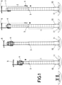
Figure 1 shows a diagram of the different stages of the manufacturing process of concrete towers for wind turbines of the present invention, where the concrete tower thus manufactured comprises a first cylindrical section and a second cylindrical section. -
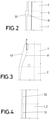
Figure 2 shows a diagram of the construction stage of the intermediate transition section on the first cylindrical section, modifying the first climbing formwork system, so that the construction of the intermediate transition section is carried out in situ. -
Figure 3 shows a diagram of the construction stage of the top section of tower, installing an upper formwork system, so that the construction of the intermediate transition section is carried out in situ. -
Figure 4 shows a diagram of an embodiment of the first cylindrical section or of the second cylindrical section of the tower of the present invention. -
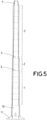
Figure 5 shows an example of embodiment of concrete tower of the present invention, where the concrete tower comprises a first cylindrical section and two second cylindrical sections. - The manufacturing process of concrete towers for wind turbines of the present invention shall be detailed below.
- The manufacturing process of concrete towers for wind turbines comprises:
- an execution stage of a first cylindrical section (1) of concrete tower by means of a first climbing formwork system (4); and
- an execution stage of a second cylindrical section (2) of concrete tower by means of the first climbing formwork system (4) so that an outer diameter of the second cylindrical section (2) is smaller than an outer diameter of the first cylindrical section (1), where the execution stage of the second cylindrical section (2) is carried out at a height greater than the execution stage of the first cylindrical section (1).
- According to the invention, the manufacturing process also comprises a construction stage of an intermediate transition section (3) before the execution stage of the second cylindrical section (2) of concrete tower, where the construction stages of the intermediate transition section (3) and execution stage of the second cylindrical section (2) of concrete tower are repeated until the second cylindrical section (2) is an upper cylindrical section of concrete tower. Next, a top section (7) of concrete tower shall be constructed as shall be explained below.
- The manufacturing process comprises an assembly stage of the first climbing formwork system (4) on a lower section (10) of concrete tower manufactured prior to the execution stage of the first cylindrical section (1) of concrete tower, where, preferably, the lower section (10) of concrete tower is manufactured in situ on foundations (11) of the concrete tower.
- In a first example of embodiment, the construction stage of the intermediate transition section (3) is carried out on the first cylindrical section (1). In this way, the intermediate transition section (3) and the first cylindrical section (1) are continuously executed, without horizontal or vertical joints. This construction stage of the intermediate transition section (3) on the first cylindrical section (1) can be carried out in two ways:
- Performing, before the construction stage of the intermediate transition section (3) on the first cylindrical section (1), an adaptation stage of the first climbing formwork system (4), for the in situ construction of the intermediate transition section (3), as shown in
figure 2 , where the adaptation stage of the first climbing formwork system (4) can be performed:- o modifying an inner formwork of the first climbing formwork system (4), where, preferably, the inner formwork comprises at least one inclined section, so that it generates an inner surface (31) without steps;
- o modifying an outer formwork of the first climbing formwork system (4) or of the second climbing formwork system (5), where, preferably, the outer formwork comprises at least one inclined section, so that it generates an outer surface (32) without steps, so that the outer surface of the tower is highly aerodynamic;
- o modifying an inner formwork and an outer formwork of the first climbing formwork system (4) or of the second climbing formwork system (5), where, preferably, the inner formwork and the outer formwork comprise at least one inclined section, so that it generates an inner surface (31) without steps, and an outer surface (32) without steps, so that the outer surface of the tower is highly aerodynamic.
- Performing, before the construction stage of the intermediate transition section (3) on the first cylindrical section (1), an assembly stage of a first non-climbing formwork system for the in situ construction of the intermediate transition section (3). In this case, the manufacturing process comprises, after the construction stage of the intermediate transition section (3) on the first cylindrical section (1), a dismantling stage of the first non-climbing formwork system.
- In a second example of embodiment, the construction stage of the intermediate transition section (3) comprises a manufacturing stage of the intermediate transition section (3) in an area close to a base of the concrete tower and an installation stage of the intermediate transition section (3) manufactured in an area close to a base of the concrete tower, on the first cylindrical section (1), preferably using a crane (6) coupled to the first climbing formwork system (4). In this way, it avoids modifying the first climbing formwork system (4) and it dispenses with the concrete setting time as the intermediate transition element (3) is already prefabricated once it is installed on the first cylindrical section (1).
- The manufacturing process of concrete towers for wind turbines comprises, after the construction stage of the intermediate transition section (3) and before the execution stage of the second cylindrical section (2), an adaptation stage of an outer formwork of the first climbing formwork system (4) to the outer diameter of the second cylindrical section (2) and preferably also an adaptation stage of an inner formwork of the first climbing formwork system (4) to an inner diameter of the second cylindrical section (2).
- In a first example of embodiment, the construction stage of the top section (7) of concrete tower performed after the execution stage of the upper section of concrete tower is carried out on the upper cylindrical section of concrete tower. In this way, the upper cylindrical section and the top section (7) are continuously executed, without horizontal or vertical joints. This construction stage of the top section (7) on the upper cylindrical section can be carried out:
- Performing, before the construction stage of the top section (7) on the upper cylindrical section, an assembly stage of a second non-climbing formwork system for the in situ construction of the top section (7), where the second non-climbing formwork comprises an inner formwork and an outer formwork, where, preferably, the inner formwork and the outer formwork comprise at least one inclined section, so that they generate an inner surface (41) and an outer surface (42) which enable the connection of one coil of the wind turbine to the tower.
- In a second example of embodiment, the construction stage of the top section (7) of concrete tower comprises a manufacturing stage of the top section (7) in an area close to a base of the concrete tower. Preferably, this construction stage of the top section (7) comprises an installation stage of the top section (7) manufactured in an area close to a base of the concrete tower, on the upper cylindrical section, preferably using a crane (6) coupled to the first climbing formwork system (4). In this way, it dispenses with the concrete setting time as the top section (7) is already prefabricated once installed on the upper cylindrical section.
- The execution stage of the first cylindrical section (1) and/or the execution stage of the second cylindrical section (2) comprise the following sub-stages:
- a lifting sub-stage of a framework;
- a fixing sub-stage of the framework to the previously manufactured cylindrical section (1, 2);
- a closing sub-stage of the first climbing formwork system (4);
- a pouring sub-stage of the concrete inside the first climbing formwork system (4);
- an opening sub-stage of the first climbing formwork system (4);
- a climbing sub-stage of the first climbing formwork system (4);
- The first climbing formwork system (4) and/or the second climbing formwork system (5) comprise a set of hydraulic jacks each one of which has two climbing heads, an upper climbing head disposed on a moving part of the hydraulic jack and a lower climbing head disposed on a fixed part of the hydraulic jack.
- Each climbing head comprises a system of pins which makes it possible to be temporarily fixed to a mast which is vertically disposed on the tower surface as a guide or to the tower itself, where the upper climbing head of each hydraulic jack is also solidly joined to a main platform of the first formwork system or of the second formwork system.
- The vertical displacement of the first formwork system or of the second formwork system is achieved by means of the actuation of the hydraulic jack combined with the opening and/or closing of the climbing heads.
- Below, the concrete tower for wind turbines shall be described in detail.
- The concrete tower comprises at least two sections of constant outer diameter, a first cylindrical section (1) and a second cylindrical section (2), where the second cylindrical section (2) is higher than the first cylindrical section (1) and where an outer diameter of the second cylindrical section (2) is smaller than an outer diameter of the first cylindrical section (1).
- The first cylindrical section (1) and the second cylindrical section (2) are both intended to be executed in situ by means of a first climbing formwork system (4).
- Preferably, the concrete tower also comprises an intermediate transition section (3) disposed between the first cylindrical section (1) and the second cylindrical section (2). In a first example of embodiment, the intermediate transition section (3) is a section which is intended to be executed in situ, whilst in a second example of embodiment, the intermediate transition section (3) is a prefabricated concrete element either formed by a single piece or formed by several modules. Preferably, the prefabricated concrete element is intended to be manufactured in an area close to a base of the concrete tower.
- The intermediate transition section (3) comprises an inner surface with at least one section with truncated cone geometry (31), preferably with an upper part and a lower part, where the section with truncated cone geometry has, in the lower part, a larger diameter which is greater than or equal to an inner diameter of the first cylindrical section (1), and in the upper part a smaller diameter which is smaller than or equal to an inner diameter of the second cylindrical section (2). Preferably, the transition section (3) comprises an outer surface with cylindrical (32) or truncated cone geometry. If the transition section (3) comprises an outer surface with truncated cone geometry, said outer surface comprises an upper part and a lower part, where the outer surface with truncated cone geometry of the transition section (3) has, in the lower part, a larger diameter which is equal to an outer diameter of the first cylindrical section (1), and in the upper part a smaller diameter which is greater than or equal to an outer diameter of the second cylindrical section (2).
- The first cylindrical section (1) and/or the second cylindrical section (2) comprise at least one first sub-section (51) with a first inner diameter and a second sub-section (52) with a second inner diameter, where the second sub-section (52) is higher than the first sub-section (51) and where the first inner diameter of the first sub-section (51) is smaller than the second inner diameter of the second sub-section (52), as observed in
Figure 4 , so that the thickness of the first cylindrical section (1) and/or the second cylindrical section (2) are decreasing in height. - The concrete tower also comprises a top section (7) disposed on the second cylindrical section (2) or on an upper cylindrical section, where, preferably the top section (7) is a section which is intended to be executed in situ, or a prefabricated concrete element either formed by a single piece or formed by several modules. Preferably, the prefabricated concrete element is intended to be manufactured in the area close to the base of the concrete tower.
- The concrete tower also comprises a lower section (10) which is lower than the first cylindrical section (1) where said lower section (10) of concrete tower has an outer diameter larger than the outer diameter of the first cylindrical section (1) and where the first cylindrical section (1) is intended to be executed on the lower section (10) of concrete tower. This lower section (10) may be cylindrical or truncated cone-shaped and is executed in situ preferably by means of non-climbing formworks.
Claims (16)
- Manufacturing process of concrete towers for wind turbines comprising:an execution stage of a first section (1) of a concrete tower by means of a formwork system (4);an execution stage of a second section (2) of the concrete tower by means of the formwork system (4), where the execution stage of the second section (2) is carried out at a height greater than the execution stage of the first section (1);a construction stage of an intermediate transition section (3) before the execution stage of the second section (2) of the concrete tower;whereinthe execution stage of the first section is an execution stage of a first cylindrical section (1) with constant outer diameter and the execution stage of the second section is an execution stage of a second cylindrical section (2) with constant outer diameter, wherein the outer diameter of the second cylindrical section (2) is smaller than an outer diameter of the first cylindrical section (1);the first (1) and the second cylindrical sections (2) are both executed in situ by means of a first climbing formwork system (4), so that it is not necessary to use a second climbing formwork system;the process further comprises, after the construction stage of the intermediate transition section (3) and before the execution stage of the second cylindrical section (2), an adaption stage of an out formwork of the first climbing formwork system (4) to the outer diameter of the second cylindrical section (2).
- Manufacturing process according to claim 1, wherein the construction stages of the intermediate transition section (3) and the execution stage of the second cylindrical section (2) of the concrete tower are repeated until the second cylindrical section (2) is an upper cylindrical section of the concrete tower.
- Manufacturing process according to any of the preceding claims, comprising:
an assembly stage of the first climbing formwork system (4) on a lower section (10) of the concrete tower manufactured prior to the execution stage of the first cylindrical section (1) of the concrete tower. - Manufacturing process according to claim 3, wherein the lower section (10) of the concrete tower is manufactured in situ on a foundation (11) of the concrete tower.
- Manufacturing process according to any of the preceding claims, wherein the construction stage of the intermediate transition section (3) is carried out on the first cylindrical section (1).
- Manufacturing process according to claim 5, comprising, before the construction stage of the intermediate transition section (3) on the first cylindrical section (1), an adaptation stage of the first climbing formwork system (4), for the in situ construction of the intermediate transition section (3).
- Manufacturing process according to claim 5, comprising, before the construction stage of the intermediate transition section (3) on the first cylindrical section (1), an assembly stage of a first non-climbing formwork system for the in situ construction of the intermediate transition section (3).
- Manufacturing process according to any of claims 1 to 3, wherein the construction stage of the intermediate transition section (3) comprises a manufacturing stage of the intermediate transition section (3) in an area close to a base of the concrete tower and an installation stage of the intermediate transition section (3) on the first cylindrical section (1).
- Manufacturing process according to claim 8, comprising, after the construction stage of the intermediate transition section (3) and before the execution stage of the second cylindrical section (2), an adaptation stage of an inner formwork of the first climbing formwork system (4) to an inner diameter of the second cylindrical section (2) .
- Manufacturing process according to any of the preceding claims, wherein the execution stage of the second cylindrical section (2) is carried out so that an inner diameter of the second cylindrical section (2) is smaller than an inner diameter of the first cylindrical section (1) .
- Manufacturing process according to claim 2, comprising a construction stage of a top section (7) after the execution stage of the second cylindrical section (2), where said second cylindrical section (2) is the upper cylindrical section of the concrete tower.
- Manufacturing process according to claim 11, wherein the construction stage of the top section (7) is carried out on the upper cylindrical section of the concrete tower.
- Manufacturing process according to claim 12, comprising, before the construction stage of the top section (7) on the upper cylindrical section, an assembly stage of a second non-climbing formwork system for the in situ construction of the top section (7).
- Manufacturing process according to claim 11, wherein the construction stage of the top section (7) comprises a manufacturing stage of the top section (7) in an area close to a base of the concrete tower, and an installation stage of the top section on the upper cylindrical section.
- Manufacturing process according to any of the preceding claims, wherein the execution stage of the first cylindrical section (1) and/or the execution stage of the second cylindrical section (2) comprise the following sub-stages:a lifting sub-stage of a framework;a fixing sub-stage of the framework to the previously manufactured cylindrical section (1, 2);a closing sub-stage of the first climbing formwork system (4);a pouring sub-stage of the concrete inside the first climbing formwork system (4);an opening sub-stage of the first climbing formwork system (4);a climbing sub-stage of the first climbing formwork system (4);where said sub-stages are repeated until all of the first cylindrical section (1) and/or all of the second cylindrical section (2), respectively, has been executed.
- Manufacturing process according to any of the preceding claims, wherein the execution stage of the first cylindrical section (1) and/or the execution stage of the second cylindrical section (2) comprise a modification sub-stage of an inner formwork of the first climbing formwork system (4).
Priority Applications (5)
| Application Number | Priority Date | Filing Date | Title |
|---|---|---|---|
| EP16382082.2A EP3211154B1 (en) | 2016-02-26 | 2016-02-26 | Manufacturing process of concrete towers for wind turbines |
| ES16382082T ES2911709T3 (en) | 2016-02-26 | 2016-02-26 | Manufacturing procedure of concrete towers for wind turbines |
| DK16382082.2T DK3211154T3 (en) | 2016-02-26 | 2016-02-26 | PROCEDURE FOR MANUFACTURE OF CONCRETE TOWERS FOR WIND TURBINES |
| BR102017003456-9A BR102017003456B1 (en) | 2016-02-26 | 2017-02-21 | MANUFACTURING PROCESS OF CONCRETE TOWERS FOR WIND TURBINES |
| US15/443,606 US10738499B2 (en) | 2016-02-26 | 2017-02-27 | Concrete towers manufacturing method for wind turbines and concrete tower for wind turbine |
Applications Claiming Priority (1)
| Application Number | Priority Date | Filing Date | Title |
|---|---|---|---|
| EP16382082.2A EP3211154B1 (en) | 2016-02-26 | 2016-02-26 | Manufacturing process of concrete towers for wind turbines |
Publications (2)
| Publication Number | Publication Date |
|---|---|
| EP3211154A1 EP3211154A1 (en) | 2017-08-30 |
| EP3211154B1 true EP3211154B1 (en) | 2022-02-23 |
Family
ID=55802317
Family Applications (1)
| Application Number | Title | Priority Date | Filing Date |
|---|---|---|---|
| EP16382082.2A Active EP3211154B1 (en) | 2016-02-26 | 2016-02-26 | Manufacturing process of concrete towers for wind turbines |
Country Status (5)
| Country | Link |
|---|---|
| US (1) | US10738499B2 (en) |
| EP (1) | EP3211154B1 (en) |
| BR (1) | BR102017003456B1 (en) |
| DK (1) | DK3211154T3 (en) |
| ES (1) | ES2911709T3 (en) |
Families Citing this family (4)
| Publication number | Priority date | Publication date | Assignee | Title |
|---|---|---|---|---|
| ES2695626B2 (en) * | 2017-06-30 | 2020-05-19 | Hws Concrete Towers S L | Self-climbing device for vertical and quasi-vertical concrete surfaces and operating procedure. |
| CN111287908B (en) * | 2018-12-06 | 2022-01-04 | 上海风领新能源有限公司 | Construction method of concrete tower tube |
| JP7037516B2 (en) * | 2019-03-13 | 2022-03-16 | 日本コンクリート工業株式会社 | Manufacturing method of steel pipes for joints, upper columns, formwork for forming upper columns and upper columns |
| CN110987057A (en) * | 2019-09-30 | 2020-04-10 | 中交天津港湾工程研究院有限公司 | Hydraulic pressure is automatic monitoring system in high in clouds for creeping formwork |
Family Cites Families (54)
| Publication number | Priority date | Publication date | Assignee | Title |
|---|---|---|---|---|
| US1020005A (en) * | 1910-11-17 | 1912-03-12 | Witthoefft Collapsible Concrete Forms Company | Mold for making concrete chimneys. |
| US1301364A (en) * | 1919-01-06 | 1919-04-22 | Benjamin Biggs | Form for concrete silo construction. |
| US2722040A (en) * | 1951-07-25 | 1955-11-01 | Ludowici Johann Wilhelm | Erection of buildings |
| US2730207A (en) * | 1952-11-28 | 1956-01-10 | Robert E Hall | Collapsible tower and hoist |
| US2857994A (en) * | 1954-03-08 | 1958-10-28 | Patent Scaffolding Co Inc | Erection frames for sectional towers |
| US3211427A (en) * | 1961-01-03 | 1965-10-12 | Jr William T Bristow | Erection apparatus |
| US3497579A (en) * | 1965-03-25 | 1970-02-24 | Maurice Barron | Slip forming apparatus and method |
| JPS5016906B1 (en) * | 1970-06-30 | 1975-06-17 | ||
| US3871612A (en) * | 1972-08-25 | 1975-03-18 | Richard L Weaver | Cylindrical core assembly for silo construction |
| US4016228A (en) * | 1973-03-07 | 1977-04-05 | Enor Nominees Pty. Limited | Method for progressively constructing a wall of cementitious material |
| US3901472A (en) * | 1973-12-10 | 1975-08-26 | Ahlgren Nils H | Adjustable apparatus for sliding form construction |
| US3921362A (en) * | 1974-03-18 | 1975-11-25 | Pablo Cortina Ortega | Method of and means for multi-story building construction |
| US4076778A (en) * | 1975-04-22 | 1978-02-28 | Alan Charles Whitting | Climbing formwork |
| US3991969A (en) * | 1975-11-26 | 1976-11-16 | Oxyer Ronald A | Form positioning apparatus |
| SE428947B (en) * | 1979-03-16 | 1983-08-01 | John Paul Pettersson | EXPANDABLE SLIDING FORM |
| US4272465A (en) * | 1979-05-09 | 1981-06-09 | Hough Reginald D | Method for multi-storied concrete construction and apparatus therefor |
| US4272929A (en) * | 1979-08-23 | 1981-06-16 | Hanson Bror H | Tower and method of construction |
| US4403460A (en) * | 1981-10-01 | 1983-09-13 | Pittsburgh-Des Moines Corporation | Method of erecting an elevated tank using formwork |
| NO157831C (en) * | 1982-10-21 | 1988-06-08 | Selmer As Ing F | FRALAND'S PLATFORM CONSTRUCTION OF ARMED CONCRETE WITH UPPER CONVERSING CARRIERS AND SLIDE FORCE FOR USE IN CASTING THE CARRIERS. |
| US4915345A (en) * | 1987-12-18 | 1990-04-10 | Symons Corporation | Concrete forming system for curved walls |
| US5072555A (en) * | 1988-11-25 | 1991-12-17 | Geiger David H | Super high-rise tower |
| US4974700A (en) * | 1989-06-12 | 1990-12-04 | Gates & Sons, Inc. | Movable support mechanism for construction of elevator shafts and the like |
| US5125617A (en) * | 1990-03-29 | 1992-06-30 | Miller Alan P | Adjustable radius walers for forming |
| DE4116439C1 (en) * | 1991-05-18 | 1992-08-27 | Maier G Paschal Werk | |
| US5946881A (en) * | 1997-12-01 | 1999-09-07 | Chatelain; Paul J. | Form for casting a concrete fence post in situ and process for its use |
| US6260311B1 (en) * | 1999-02-11 | 2001-07-17 | Peter Vladikovic | Concrete form suspension system and method |
| US6299137B1 (en) * | 1999-04-28 | 2001-10-09 | Wesley Allen Bainter | Hydraulic grain storage bin lifting system |
| JP3546754B2 (en) * | 1999-04-30 | 2004-07-28 | Jfeスチール株式会社 | Short-term refurbishment and construction method of blast furnace and mounting device for ring-shaped block |
| US6557817B2 (en) * | 2000-01-18 | 2003-05-06 | Wilian Holding Company | Wall climbing form hoist |
| US6425712B1 (en) * | 2000-09-07 | 2002-07-30 | Liftplate International | Method and apparatus for providing lateral support to a post |
| US6470645B1 (en) * | 2000-11-09 | 2002-10-29 | Beaird Industries, Inc. | Method for making and erecting a wind tower |
| AT410343B (en) * | 2001-01-24 | 2003-03-25 | Rund Stahl Bau Gmbh & Co | METHOD FOR PRODUCING A TOWER-LIKE CONSTRUCTION |
| US7004737B2 (en) * | 2001-08-20 | 2006-02-28 | Matthew Russell | Methods and apparatus for forming concrete structures |
| ES1058539Y (en) * | 2004-10-11 | 2005-04-01 | Inneo21 S L | PERFECTED MODULAR TOWER STRUCTURE FOR WIND TURBINES AND OTHER APPLICATIONS. |
| WO2007012201A1 (en) * | 2005-07-25 | 2007-02-01 | The University Of Manitoba | Composite wind tower systems and methods of manufacture |
| US8316614B2 (en) * | 2007-11-29 | 2012-11-27 | Vestas Wind Systems A/S | Method for establishing a wind turbine on a site |
| US20100281818A1 (en) * | 2009-05-07 | 2010-11-11 | Southworth George L | Method for building wind turbine tower |
| WO2011091799A1 (en) * | 2010-02-01 | 2011-08-04 | Conelto Aps | A tower construction and a method for erecting the tower construction |
| US8621817B1 (en) * | 2010-12-03 | 2014-01-07 | Kenneth Robert Kreizinger | Vertical vibrating screed |
| DK2374966T3 (en) * | 2010-04-06 | 2016-11-07 | Soletanche Freyssinet | A method of building a hybrid tower for a wind turbine |
| US8931235B2 (en) * | 2010-06-15 | 2015-01-13 | Brookes H. Baker | Method for erecting a facility producing electrical energy from wind |
| PT2630307T (en) * | 2010-10-20 | 2016-10-27 | Mhi Vestas Offshore Wind As | Foundation for a wind turbine and method of making same |
| DE102011102316A1 (en) * | 2011-05-25 | 2012-11-29 | Philipp Wagner | Multi-stage process for the erection and maintenance of wind turbines |
| DE102011107804A1 (en) * | 2011-07-17 | 2013-01-17 | Philipp Wagner | Construction principle for tower construction for wind turbines |
| DE102011079314A1 (en) * | 2011-07-18 | 2013-01-24 | Rolf J. Werner | Tower-shaped structure |
| DE102011053017A1 (en) * | 2011-08-26 | 2013-02-28 | Max Bögl Wind AG | Method for erecting a tower construction and tower construction |
| WO2013120889A1 (en) * | 2012-02-17 | 2013-08-22 | Siemens Aktiengesellschaft | Tower |
| WO2014021927A2 (en) * | 2012-08-03 | 2014-02-06 | Lockwood James D | Precast concrete post tensioned segmented wind turbine tower |
| US9617752B2 (en) * | 2012-09-03 | 2017-04-11 | X-Tower Construction GmbH | Tower construction of a wind turbine and method for stabilizing a tower construction of a wind turbine |
| EP2735674B1 (en) * | 2012-11-21 | 2015-09-30 | Siemens Aktiengesellschaft | Slipformed concrete tower |
| US9032674B2 (en) * | 2013-03-05 | 2015-05-19 | Siemens Aktiengesellschaft | Wind turbine tower arrangement |
| DK2824057T3 (en) * | 2013-07-11 | 2017-09-11 | Siemens Ag | Lifting of a tower segment |
| EP3099866B1 (en) * | 2014-01-31 | 2020-09-09 | Gregory John Neighbours | A concrete tower and related formwork and related method of construction |
| CA2946081A1 (en) * | 2014-04-16 | 2015-10-22 | University Of Southern California | Automated construction of towers and columns |
-
2016
- 2016-02-26 EP EP16382082.2A patent/EP3211154B1/en active Active
- 2016-02-26 ES ES16382082T patent/ES2911709T3/en active Active
- 2016-02-26 DK DK16382082.2T patent/DK3211154T3/en active
-
2017
- 2017-02-21 BR BR102017003456-9A patent/BR102017003456B1/en active IP Right Grant
- 2017-02-27 US US15/443,606 patent/US10738499B2/en active Active
Also Published As
| Publication number | Publication date |
|---|---|
| BR102017003456A2 (en) | 2017-11-21 |
| BR102017003456B1 (en) | 2023-01-10 |
| ES2911709T3 (en) | 2022-05-20 |
| US20170247901A1 (en) | 2017-08-31 |
| BR102017003456A8 (en) | 2022-09-13 |
| US10738499B2 (en) | 2020-08-11 |
| EP3211154A1 (en) | 2017-08-30 |
| DK3211154T3 (en) | 2022-05-02 |
Similar Documents
| Publication | Publication Date | Title |
|---|---|---|
| EP2374966B1 (en) | Method of building a hybrid tower for a wind generator | |
| US10738499B2 (en) | Concrete towers manufacturing method for wind turbines and concrete tower for wind turbine | |
| EP2541047B1 (en) | Wind turbine assembling method and wind turbine assembled according to said method | |
| CN102482892B (en) | Telescopic tower assembly and method | |
| EP2479430B1 (en) | Method for assembling shell segments for forming tower sections of a hybrid wind turbine tower | |
| EP2886751B1 (en) | Method for the assembly of frustoconical concrete towers | |
| DK2735674T3 (en) | Sliding shell concrete tower | |
| US9016005B2 (en) | Process and unit for the attachment of a wind turbine's tower to a foundation and wind turbine incorporating said unit | |
| MX2014006813A (en) | Assembly process of a telescopic tower. | |
| EP3329119A2 (en) | Equipment tower having a concrete plinth | |
| AU2015341008B2 (en) | Method for installing a hollow concrete tower made from more than one segment and corresponding hollow concrete tower | |
| EP2980337B1 (en) | Method for assembling diminishing section concrete towers for wind turbines | |
| EP3428447B1 (en) | Pre-assembly slab system for concrete wind turbine towers and method for assembling a pre-assembly slab system for concrete wind turbine towers | |
| EP3786393B1 (en) | Movable module for hoisting telescopic towers and method for hoisting telescopic towers | |
| EP2857615A1 (en) | Mounting method and mounting device of a concrete tower formed with precast pieces | |
| AU2011201502B8 (en) | Method of building a hybrid tower for a wind generator | |
| EP4151854A1 (en) | Telescopic tower construction method | |
| CN111315947A (en) | Method for building a tower having a multi-part tower segment and segments in a multi-part tower segment of a tower |
Legal Events
| Date | Code | Title | Description |
|---|---|---|---|
| PUAI | Public reference made under article 153(3) epc to a published international application that has entered the european phase |
Free format text: ORIGINAL CODE: 0009012 |
|
| STAA | Information on the status of an ep patent application or granted ep patent |
Free format text: STATUS: THE APPLICATION HAS BEEN PUBLISHED |
|
| AK | Designated contracting states |
Kind code of ref document: A1 Designated state(s): AL AT BE BG CH CY CZ DE DK EE ES FI FR GB GR HR HU IE IS IT LI LT LU LV MC MK MT NL NO PL PT RO RS SE SI SK SM TR |
|
| AX | Request for extension of the european patent |
Extension state: BA ME |
|
| STAA | Information on the status of an ep patent application or granted ep patent |
Free format text: STATUS: REQUEST FOR EXAMINATION WAS MADE |
|
| 17P | Request for examination filed |
Effective date: 20180104 |
|
| RBV | Designated contracting states (corrected) |
Designated state(s): AL AT BE BG CH CY CZ DE DK EE ES FI FR GB GR HR HU IE IS IT LI LT LU LV MC MK MT NL NO PL PT RO RS SE SI SK SM TR |
|
| STAA | Information on the status of an ep patent application or granted ep patent |
Free format text: STATUS: EXAMINATION IS IN PROGRESS |
|
| 17Q | First examination report despatched |
Effective date: 20180316 |
|
| RAP1 | Party data changed (applicant data changed or rights of an application transferred) |
Owner name: NORDEX ENERGY SPAIN, S.A. |
|
| STAA | Information on the status of an ep patent application or granted ep patent |
Free format text: STATUS: EXAMINATION IS IN PROGRESS |
|
| GRAP | Despatch of communication of intention to grant a patent |
Free format text: ORIGINAL CODE: EPIDOSNIGR1 |
|
| STAA | Information on the status of an ep patent application or granted ep patent |
Free format text: STATUS: GRANT OF PATENT IS INTENDED |
|
| INTG | Intention to grant announced |
Effective date: 20210316 |
|
| GRAJ | Information related to disapproval of communication of intention to grant by the applicant or resumption of examination proceedings by the epo deleted |
Free format text: ORIGINAL CODE: EPIDOSDIGR1 |
|
| STAA | Information on the status of an ep patent application or granted ep patent |
Free format text: STATUS: EXAMINATION IS IN PROGRESS |
|
| INTC | Intention to grant announced (deleted) | ||
| GRAP | Despatch of communication of intention to grant a patent |
Free format text: ORIGINAL CODE: EPIDOSNIGR1 |
|
| STAA | Information on the status of an ep patent application or granted ep patent |
Free format text: STATUS: GRANT OF PATENT IS INTENDED |
|
| INTG | Intention to grant announced |
Effective date: 20211019 |
|
| GRAS | Grant fee paid |
Free format text: ORIGINAL CODE: EPIDOSNIGR3 |
|
| GRAA | (expected) grant |
Free format text: ORIGINAL CODE: 0009210 |
|
| STAA | Information on the status of an ep patent application or granted ep patent |
Free format text: STATUS: THE PATENT HAS BEEN GRANTED |
|
| AK | Designated contracting states |
Kind code of ref document: B1 Designated state(s): AL AT BE BG CH CY CZ DE DK EE ES FI FR GB GR HR HU IE IS IT LI LT LU LV MC MK MT NL NO PL PT RO RS SE SI SK SM TR |
|
| REG | Reference to a national code |
Ref country code: GB Ref legal event code: FG4D |
|
| REG | Reference to a national code |
Ref country code: CH Ref legal event code: EP |
|
| REG | Reference to a national code |
Ref country code: DE Ref legal event code: R096 Ref document number: 602016069319 Country of ref document: DE |
|
| REG | Reference to a national code |
Ref country code: AT Ref legal event code: REF Ref document number: 1470585 Country of ref document: AT Kind code of ref document: T Effective date: 20220315 |
|
| REG | Reference to a national code |
Ref country code: IE Ref legal event code: FG4D |
|
| REG | Reference to a national code |
Ref country code: FI Ref legal event code: FGE |
|
| REG | Reference to a national code |
Ref country code: DK Ref legal event code: T3 Effective date: 20220426 |
|
| REG | Reference to a national code |
Ref country code: NL Ref legal event code: FP |
|
| REG | Reference to a national code |
Ref country code: SE Ref legal event code: TRGR |
|
| REG | Reference to a national code |
Ref country code: ES Ref legal event code: FG2A Ref document number: 2911709 Country of ref document: ES Kind code of ref document: T3 Effective date: 20220520 |
|
| REG | Reference to a national code |
Ref country code: LT Ref legal event code: MG9D |
|
| REG | Reference to a national code |
Ref country code: NO Ref legal event code: T2 Effective date: 20220223 |
|
| REG | Reference to a national code |
Ref country code: AT Ref legal event code: MK05 Ref document number: 1470585 Country of ref document: AT Kind code of ref document: T Effective date: 20220223 |
|
| PG25 | Lapsed in a contracting state [announced via postgrant information from national office to epo] |
Ref country code: RS Free format text: LAPSE BECAUSE OF FAILURE TO SUBMIT A TRANSLATION OF THE DESCRIPTION OR TO PAY THE FEE WITHIN THE PRESCRIBED TIME-LIMIT Effective date: 20220223 Ref country code: PT Free format text: LAPSE BECAUSE OF FAILURE TO SUBMIT A TRANSLATION OF THE DESCRIPTION OR TO PAY THE FEE WITHIN THE PRESCRIBED TIME-LIMIT Effective date: 20220623 Ref country code: LT Free format text: LAPSE BECAUSE OF FAILURE TO SUBMIT A TRANSLATION OF THE DESCRIPTION OR TO PAY THE FEE WITHIN THE PRESCRIBED TIME-LIMIT Effective date: 20220223 Ref country code: HR Free format text: LAPSE BECAUSE OF FAILURE TO SUBMIT A TRANSLATION OF THE DESCRIPTION OR TO PAY THE FEE WITHIN THE PRESCRIBED TIME-LIMIT Effective date: 20220223 Ref country code: BG Free format text: LAPSE BECAUSE OF FAILURE TO SUBMIT A TRANSLATION OF THE DESCRIPTION OR TO PAY THE FEE WITHIN THE PRESCRIBED TIME-LIMIT Effective date: 20220523 |
|
| PG25 | Lapsed in a contracting state [announced via postgrant information from national office to epo] |
Ref country code: PL Free format text: LAPSE BECAUSE OF FAILURE TO SUBMIT A TRANSLATION OF THE DESCRIPTION OR TO PAY THE FEE WITHIN THE PRESCRIBED TIME-LIMIT Effective date: 20220223 Ref country code: LV Free format text: LAPSE BECAUSE OF FAILURE TO SUBMIT A TRANSLATION OF THE DESCRIPTION OR TO PAY THE FEE WITHIN THE PRESCRIBED TIME-LIMIT Effective date: 20220223 Ref country code: GR Free format text: LAPSE BECAUSE OF FAILURE TO SUBMIT A TRANSLATION OF THE DESCRIPTION OR TO PAY THE FEE WITHIN THE PRESCRIBED TIME-LIMIT Effective date: 20220524 Ref country code: AT Free format text: LAPSE BECAUSE OF FAILURE TO SUBMIT A TRANSLATION OF THE DESCRIPTION OR TO PAY THE FEE WITHIN THE PRESCRIBED TIME-LIMIT Effective date: 20220223 |
|
| PG25 | Lapsed in a contracting state [announced via postgrant information from national office to epo] |
Ref country code: IS Free format text: LAPSE BECAUSE OF FAILURE TO SUBMIT A TRANSLATION OF THE DESCRIPTION OR TO PAY THE FEE WITHIN THE PRESCRIBED TIME-LIMIT Effective date: 20220623 |
|
| REG | Reference to a national code |
Ref country code: CH Ref legal event code: PL |
|
| REG | Reference to a national code |
Ref country code: BE Ref legal event code: MM Effective date: 20220228 |
|
| PG25 | Lapsed in a contracting state [announced via postgrant information from national office to epo] |
Ref country code: SM Free format text: LAPSE BECAUSE OF FAILURE TO SUBMIT A TRANSLATION OF THE DESCRIPTION OR TO PAY THE FEE WITHIN THE PRESCRIBED TIME-LIMIT Effective date: 20220223 Ref country code: SK Free format text: LAPSE BECAUSE OF FAILURE TO SUBMIT A TRANSLATION OF THE DESCRIPTION OR TO PAY THE FEE WITHIN THE PRESCRIBED TIME-LIMIT Effective date: 20220223 Ref country code: RO Free format text: LAPSE BECAUSE OF FAILURE TO SUBMIT A TRANSLATION OF THE DESCRIPTION OR TO PAY THE FEE WITHIN THE PRESCRIBED TIME-LIMIT Effective date: 20220223 Ref country code: LU Free format text: LAPSE BECAUSE OF NON-PAYMENT OF DUE FEES Effective date: 20220226 Ref country code: EE Free format text: LAPSE BECAUSE OF FAILURE TO SUBMIT A TRANSLATION OF THE DESCRIPTION OR TO PAY THE FEE WITHIN THE PRESCRIBED TIME-LIMIT Effective date: 20220223 Ref country code: CZ Free format text: LAPSE BECAUSE OF FAILURE TO SUBMIT A TRANSLATION OF THE DESCRIPTION OR TO PAY THE FEE WITHIN THE PRESCRIBED TIME-LIMIT Effective date: 20220223 |
|
| REG | Reference to a national code |
Ref country code: DE Ref legal event code: R097 Ref document number: 602016069319 Country of ref document: DE |
|
| PG25 | Lapsed in a contracting state [announced via postgrant information from national office to epo] |
Ref country code: MC Free format text: LAPSE BECAUSE OF FAILURE TO SUBMIT A TRANSLATION OF THE DESCRIPTION OR TO PAY THE FEE WITHIN THE PRESCRIBED TIME-LIMIT Effective date: 20220223 Ref country code: AL Free format text: LAPSE BECAUSE OF FAILURE TO SUBMIT A TRANSLATION OF THE DESCRIPTION OR TO PAY THE FEE WITHIN THE PRESCRIBED TIME-LIMIT Effective date: 20220223 |
|
| PLBE | No opposition filed within time limit |
Free format text: ORIGINAL CODE: 0009261 |
|
| STAA | Information on the status of an ep patent application or granted ep patent |
Free format text: STATUS: NO OPPOSITION FILED WITHIN TIME LIMIT |
|
| GBPC | Gb: european patent ceased through non-payment of renewal fee |
Effective date: 20220523 |
|
| PG25 | Lapsed in a contracting state [announced via postgrant information from national office to epo] |
Ref country code: LI Free format text: LAPSE BECAUSE OF NON-PAYMENT OF DUE FEES Effective date: 20220228 Ref country code: IE Free format text: LAPSE BECAUSE OF NON-PAYMENT OF DUE FEES Effective date: 20220226 Ref country code: FR Free format text: LAPSE BECAUSE OF NON-PAYMENT OF DUE FEES Effective date: 20220423 Ref country code: CH Free format text: LAPSE BECAUSE OF NON-PAYMENT OF DUE FEES Effective date: 20220228 |
|
| 26N | No opposition filed |
Effective date: 20221124 |
|
| PG25 | Lapsed in a contracting state [announced via postgrant information from national office to epo] |
Ref country code: SI Free format text: LAPSE BECAUSE OF FAILURE TO SUBMIT A TRANSLATION OF THE DESCRIPTION OR TO PAY THE FEE WITHIN THE PRESCRIBED TIME-LIMIT Effective date: 20220223 Ref country code: BE Free format text: LAPSE BECAUSE OF NON-PAYMENT OF DUE FEES Effective date: 20220228 |
|
| PGFP | Annual fee paid to national office [announced via postgrant information from national office to epo] |
Ref country code: NL Payment date: 20230220 Year of fee payment: 8 |
|
| PGFP | Annual fee paid to national office [announced via postgrant information from national office to epo] |
Ref country code: NO Payment date: 20230217 Year of fee payment: 8 Ref country code: FI Payment date: 20230222 Year of fee payment: 8 Ref country code: ES Payment date: 20230317 Year of fee payment: 8 Ref country code: DK Payment date: 20230220 Year of fee payment: 8 |
|
| PG25 | Lapsed in a contracting state [announced via postgrant information from national office to epo] |
Ref country code: GB Free format text: LAPSE BECAUSE OF NON-PAYMENT OF DUE FEES Effective date: 20220523 |
|
| PGFP | Annual fee paid to national office [announced via postgrant information from national office to epo] |
Ref country code: SE Payment date: 20230220 Year of fee payment: 8 Ref country code: DE Payment date: 20230216 Year of fee payment: 8 |
|
| P01 | Opt-out of the competence of the unified patent court (upc) registered |
Effective date: 20230529 |
|
| PG25 | Lapsed in a contracting state [announced via postgrant information from national office to epo] |
Ref country code: IT Free format text: LAPSE BECAUSE OF FAILURE TO SUBMIT A TRANSLATION OF THE DESCRIPTION OR TO PAY THE FEE WITHIN THE PRESCRIBED TIME-LIMIT Effective date: 20220223 |
|
| PG25 | Lapsed in a contracting state [announced via postgrant information from national office to epo] |
Ref country code: HU Free format text: LAPSE BECAUSE OF FAILURE TO SUBMIT A TRANSLATION OF THE DESCRIPTION OR TO PAY THE FEE WITHIN THE PRESCRIBED TIME-LIMIT; INVALID AB INITIO Effective date: 20160226 |
|
| PGFP | Annual fee paid to national office [announced via postgrant information from national office to epo] |
Ref country code: NL Payment date: 20240220 Year of fee payment: 9 Ref country code: ES Payment date: 20240319 Year of fee payment: 9 |