EP3210922A1 - Elevator run profile modification for smooth rescue - Google Patents
Elevator run profile modification for smooth rescue Download PDFInfo
- Publication number
- EP3210922A1 EP3210922A1 EP17157791.9A EP17157791A EP3210922A1 EP 3210922 A1 EP3210922 A1 EP 3210922A1 EP 17157791 A EP17157791 A EP 17157791A EP 3210922 A1 EP3210922 A1 EP 3210922A1
- Authority
- EP
- European Patent Office
- Prior art keywords
- velocity
- elevator car
- controller
- actual
- determining
- Prior art date
- Legal status (The legal status is an assumption and is not a legal conclusion. Google has not performed a legal analysis and makes no representation as to the accuracy of the status listed.)
- Granted
Links
Images


Classifications
-
- B—PERFORMING OPERATIONS; TRANSPORTING
- B66—HOISTING; LIFTING; HAULING
- B66B—ELEVATORS; ESCALATORS OR MOVING WALKWAYS
- B66B1/00—Control systems of elevators in general
- B66B1/24—Control systems with regulation, i.e. with retroactive action, for influencing travelling speed, acceleration, or deceleration
- B66B1/28—Control systems with regulation, i.e. with retroactive action, for influencing travelling speed, acceleration, or deceleration electrical
- B66B1/30—Control systems with regulation, i.e. with retroactive action, for influencing travelling speed, acceleration, or deceleration electrical effective on driving gear, e.g. acting on power electronics, on inverter or rectifier controlled motor
-
- B—PERFORMING OPERATIONS; TRANSPORTING
- B66—HOISTING; LIFTING; HAULING
- B66B—ELEVATORS; ESCALATORS OR MOVING WALKWAYS
- B66B5/00—Applications of checking, fault-correcting, or safety devices in elevators
- B66B5/02—Applications of checking, fault-correcting, or safety devices in elevators responsive to abnormal operating conditions
- B66B5/028—Safety devices separate from control system in case of power failure, for hydraulical lifts, e.g. braking the hydraulic jack
-
- B—PERFORMING OPERATIONS; TRANSPORTING
- B66—HOISTING; LIFTING; HAULING
- B66B—ELEVATORS; ESCALATORS OR MOVING WALKWAYS
- B66B1/00—Control systems of elevators in general
- B66B1/34—Details, e.g. call counting devices, data transmission from car to control system, devices giving information to the control system
- B66B1/3407—Setting or modification of parameters of the control system
-
- B—PERFORMING OPERATIONS; TRANSPORTING
- B66—HOISTING; LIFTING; HAULING
- B66B—ELEVATORS; ESCALATORS OR MOVING WALKWAYS
- B66B1/00—Control systems of elevators in general
- B66B1/24—Control systems with regulation, i.e. with retroactive action, for influencing travelling speed, acceleration, or deceleration
- B66B1/28—Control systems with regulation, i.e. with retroactive action, for influencing travelling speed, acceleration, or deceleration electrical
- B66B1/285—Control systems with regulation, i.e. with retroactive action, for influencing travelling speed, acceleration, or deceleration electrical with the use of a speed pattern generator
-
- B—PERFORMING OPERATIONS; TRANSPORTING
- B66—HOISTING; LIFTING; HAULING
- B66B—ELEVATORS; ESCALATORS OR MOVING WALKWAYS
- B66B1/00—Control systems of elevators in general
- B66B1/34—Details, e.g. call counting devices, data transmission from car to control system, devices giving information to the control system
- B66B1/36—Means for stopping the cars, cages, or skips at predetermined levels
-
- B—PERFORMING OPERATIONS; TRANSPORTING
- B66—HOISTING; LIFTING; HAULING
- B66B—ELEVATORS; ESCALATORS OR MOVING WALKWAYS
- B66B5/00—Applications of checking, fault-correcting, or safety devices in elevators
- B66B5/02—Applications of checking, fault-correcting, or safety devices in elevators responsive to abnormal operating conditions
- B66B5/021—Applications of checking, fault-correcting, or safety devices in elevators responsive to abnormal operating conditions the abnormal operating conditions being independent of the system
-
- B—PERFORMING OPERATIONS; TRANSPORTING
- B66—HOISTING; LIFTING; HAULING
- B66B—ELEVATORS; ESCALATORS OR MOVING WALKWAYS
- B66B5/00—Applications of checking, fault-correcting, or safety devices in elevators
- B66B5/02—Applications of checking, fault-correcting, or safety devices in elevators responsive to abnormal operating conditions
- B66B5/027—Applications of checking, fault-correcting, or safety devices in elevators responsive to abnormal operating conditions to permit passengers to leave an elevator car in case of failure, e.g. moving the car to a reference floor or unlocking the door
-
- B—PERFORMING OPERATIONS; TRANSPORTING
- B66—HOISTING; LIFTING; HAULING
- B66B—ELEVATORS; ESCALATORS OR MOVING WALKWAYS
- B66B2201/00—Aspects of control systems of elevators
Definitions
- the subject matter disclosed herein relates generally to the field of elevator systems, and specifically to a method and apparatus for bringing an elevator to a controlled stop when power from an external power source is unavailable.
- a typical elevator system includes a car and a counterweight disposed within a hoistway, a plurality of tension ropes that interconnect the car and counterweight, and a drive unit having a drive sheave engaged with the tension ropes to drive the car and the counterweight.
- the ropes, and thereby the car and counterweight, are driven by rotating the drive sheave.
- the drive unit and its associated equipment were housed in a separate machine room.
- Newer elevator systems have eliminated the need for a separate machine room by mounting the drive unit in the hoistway. These elevator systems are referred to as machine room-less systems. Traditionally elevator systems have been dependent on an external power source for operation, which complicates operation in the event external power source is unavailable.
- a method of operating an elevator system includes powering, using a battery, the elevator system when an external power source is unavailable.
- the method also includes controlling, using a controller, a plurality of components of the elevator system.
- the controlling comprises operating at least one of the battery, an elevator car, a drive unit, and a brake.
- the method further includes determining, using the controller, a run profile of the elevator car in response to a selected deceleration.
- the method yet further includes operating, using the controller, the elevator car in response to the run profile determined, and determining, using the controller, an actual velocity of the elevator car.
- further embodiments of the method may include adjusting, using the controller, the run profile to match the actual velocity when the actual velocity is less than a selected velocity.
- further embodiments of the method may include determining, using the controller, an actual electrical current of the drive unit when the actual velocity is not less than a selected velocity; and adjusting, using the controller, the run profile when the actual electrical current is above a selected electrical current.
- further embodiments of the method may include determining, using the controller, an actual electrical current of the drive unit when the actual velocity is not less than a selected velocity; and maintaining, using the controller, the run profile when the actual electrical current is not above a selected electrical current.
- further embodiments of the method may include determining, using the controller, a projected stop position and a velocity of the elevator car; and commanding, using the controller, the brake to stop the elevator car when the projected stop position is within a selected stop position range and the velocity is within a selected velocity range.
- further embodiments of the method may include determining, using the controller, a projected stop position and a velocity of the elevator car; and determining, using the controller, an actual velocity of the elevator car when the projected stop position is not within a selected stop position range or the velocity is not within a selected velocity range.
- an apparatus for operating an elevator system includes a battery to power the elevator system when an external power source is unavailable, an elevator car, a drive unit, a brake, and a controller to control a plurality of components of the elevator system.
- the controlling comprises operating at least one of the battery, the elevator car, the drive unit, and the brake.
- the controller performs operations comprising: determining a run profile of the elevator car in response to a selected deceleration, operating the elevator car in response to the run profile determined, and determining an actual velocity of the elevator car.
- further embodiments of the apparatus may include adjusting the run profile to match the actual velocity when the actual velocity is less than a selected velocity.
- further embodiments of the apparatus may include determining an actual electrical current of the drive unit when the actual velocity is not less than a selected velocity; and adjusting the run profile when the actual electrical current is above a selected electrical current.
- further embodiments of the apparatus may include determining an actual electrical current of the drive unit when the actual velocity is not less than a selected velocity; and maintaining the run profile when the actual electrical current is not above a selected electrical current.
- further embodiments of the apparatus may include determining a projected stop position and a velocity of the elevator car; and commanding the brake to stop the elevator car when the projected stop position is within a selected stop position range and the velocity is within a selected velocity range.
- further embodiments of the apparatus may include determining a projected stop position and a velocity of the elevator car; and determining an actual velocity of the elevator car when the projected stop position is not within a selected stop position range or the velocity is not within a selected velocity range.
- inventions of the present disclosure include an elevator system having a controller to bring an elevator car to a controlled stop when power from an external power source is unavailable. Further technical effects include that the controller avoids electrical current limit faults and velocity tracking faults, while determining an elevator run profile consistent with a selected deceleration rate.
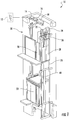
- FIG. 1 shows a schematic view of an elevator system 10, in accordance with an embodiment of the disclosure.
- FIG. 2 shows a block diagram of the elevator system 10 of FIG. 1 , in accordance with an embodiment of the disclosure.
- the elevator system 10 includes an elevator car 23 configured to move vertically upward and downward within a hoistway 50 along a plurality of car guide rails 60.
- the elevator system 10 also includes a counterweight 28 operably connected to the elevator car 23 via a pulley system 26.
- the counterweight 28 is configured to move vertically upward and downward within the hoistway 50.
- the counterweight 28 moves in a direction generally opposite the movement of the elevator car 23, as is known in conventional elevator systems. Movement of the counterweight 28 is guided by counterweight guide rails 70 mounted within the hoistway 50.
- the elevator system 10 also includes an alternating current (AC) power source 12, such as an electrical main line (e.g., 230 volt, single phase).
- the AC power is provided from the AC power source 12 to a switch panel 14, which may include circuit breakers, meters, etc. From the switch panel 14, the AC power is provided to a battery charger 16, which converts the AC power to direct current (DC) power to charge a battery 18.
- the battery 18 may be a lead-acid, lithium ion or other type of battery.
- the battery 18 may power the elevator system 10 when an external power source (e.g. AC power source 12) is unavailable.
- the DC power flows through the controller 30 to a drive unit 20, which inverts the DC power from the battery 18 to AC drive signals.
- the drive unit 20 drives a machine 22 to impart motion to the elevator car 23 via a traction sheave of the machine 22.
- the AC drive signals may be multiphase (e.g., three-phase) drive signals for a three-phase motor in the machine 22.
- the machine 22 also includes a brake 24 that can be activated to stop the machine 22 and elevator car 23.
- the drive unit 20 converts DC power from battery 18 to AC power for driving machine 22 in motoring mode.
- Motoring mode refers to situations where the machine 22 is drawing current from the drive unit 20. For example, motoring mode may occur when an empty elevator car is traveling downwards or a loaded elevator car is traveling upwards.
- the drive unit 20 also converts AC power from machine 22 to DC power for charging battery 18 when operating in regenerative mode.
- Regenerative mode refers to situations where the drive unit 20 receives current from the machine 22 (which acts as a generator) and supplies current back to the AC power source 12. For example, regenerative mode may occur when an empty elevator car is traveling upwards or when a loaded elevator car is traveling downwards.
- motoring mode and regenerative mode may occur in more than just the few examples described above and are within the scope of this disclosure.
- the controller 30 is responsible for controlling the operation of the elevator system 10.
- the controller 30 may include a processor and an associated memory.
- the processor may be but is not limited to a single-processor or multiprocessor system of any of a wide array of possible architectures, including field programmable gate array (FPGA), central processing unit (CPU), application specific integrated circuits (ASIC), digital signal processor (DSP) or graphics processing unit (GPU) hardware arranged homogenously or heterogeneously.
- the memory may be but is not limited to a random access memory (RAM), read only memory (ROM), or other electronic, optical, magnetic or any other computer readable medium.
- the controller 30 is responsible for avoiding electrical current limit faults and velocity tracking faults, while determining a run profile consistent with a selected deceleration rate.
- the run profile may refer to the position, velocity, and/or acceleration of the elevator car 23 as it reaches a selected destination, which may be a safe location for rescue and/or egress from the elevator car 23.
- the run profile may be adjusted by actions including but not limited to changing the velocity of the drive unit 20, the rotational velocity of the traction sheave, or a combination comprising at least one of the foregoing.
- the controller 30 must factor in multiple variables including but not limited to the load, friction, imbalance, and other possible sources of variation.
- the controller 30 adjusts the run profile to match the deceleration due to gravity.
- the controller 30 dictates a run profile that would allow it to keep a balance between energy generated and energy being supplied back to the battery 18 and/or dissipated as heat (i.e. sinking). If the generated energy is more than the amount of energy(e.g. electrical current) that the drive unit 20 is capable of sinking, then the run profile would be adjusted in real time to lower the generated energy.
- utilizing electrical current of the drive unit 20 and/or velocity of the elevator car 23 allows the controller 30 to adapt to hoistway loss variations, load weighing inaccuracies and load imbalance without needing a complex system model or complex parameterization to choose or predict the required deceleration rate to avoid electrical current limit faults or velocity tracking faults.
- FIG. 3 shows a block diagram of a smooth rescue software 300 architecture of the elevator system 10 of FIG. 1 , in accordance with an embodiment of the disclosure.
- the smooth rescue software 300 may be controlled by the controller 30 and may be responsible for bringing the elevator car 23 to a controlled stop in the event the external AC power source 12 is unavailable.
- the controller 30 utilizes the smooth rescue software 300 to avoid electrical current limit faults and velocity tracking faults, while determining a run profile consistent with a selected deceleration rate, as described above.
- the controller 30 may initiate the smooth rescue software 300 when a power loss event occurs at block 304. Once the power lost event has occurred, the smooth rescue software 300 may dictate a run profile based on a selected deceleration at block 306.
- the process of dictating a run profile may include determining a run profile and operating the elevator car in response to the run profile determined.
- the run profile dictates a certain speed and/or deceleration of the elevator car 23 to transition the elevator car 23 to a landing.
- the smooth rescue software 300 may determine the actual velocity of the elevator car 23 and compare the actual velocity to a selected velocity from the dictated run profile at block 308. If the actual velocity is determined to be less than the dictated velocity (i.e., motoring mode), then the smooth rescue software 300 may adjust the run profile to match the actual velocity at block 310. Then the smooth rescue software 300 may check whether the position and velocity stop criteria are met at bock 316, which is discussed later.
- the smooth rescue software 300 may check whether the actual electrical current flowing into the drive unit 20 is above a selected electrical current at block 312.
- the selected electrical current may be a preset fault limit (e.g. of the drive unit 20). If the actual electrical current flowing into the drive unit 20 is above the selected electrical current at block 312, then the smooth rescue software 300 may adjust the run profile to limit the electrical current at block 314 and next check whether the position and velocity stop criteria are met at bock 316.
- Block 314 is used to reduce the amount of current being sunk into the machine 22 so that current sinking limits of the machine are not exceeded.
- the smooth rescue software 300 may maintain the run profile and check whether the position and velocity stop criteria are met at bock 316.
- the position and velocity stop criteria may include a selected stop position range and a selected velocity range of the elevator car 23.
- the position and velocity stop criteria may be met if a projected stop position is within the selected stop position range and a velocity of the elevator car 23 is within the selected velocity range.
- the velocity referred to is the velocity of the elevator car 23 as it approaches the projected stop position. If the velocity is too high, the elevator car may need to decelerate too fast to reach the projected stop position.
- the smooth rescue software 300 may drop the brake 24 at block 318. If the position and velocity stop criteria are not met, then the smooth rescue software 300 may return back to block 306 to dictate the run profile based on a selected deceleration.
Landscapes
- Engineering & Computer Science (AREA)
- Automation & Control Theory (AREA)
- Computer Networks & Wireless Communication (AREA)
- Maintenance And Inspection Apparatuses For Elevators (AREA)
- Elevator Control (AREA)
Abstract
Description
- The subject matter disclosed herein relates generally to the field of elevator systems, and specifically to a method and apparatus for bringing an elevator to a controlled stop when power from an external power source is unavailable.
- A typical elevator system includes a car and a counterweight disposed within a hoistway, a plurality of tension ropes that interconnect the car and counterweight, and a drive unit having a drive sheave engaged with the tension ropes to drive the car and the counterweight. The ropes, and thereby the car and counterweight, are driven by rotating the drive sheave. Traditionally, the drive unit and its associated equipment were housed in a separate machine room.
- Newer elevator systems have eliminated the need for a separate machine room by mounting the drive unit in the hoistway. These elevator systems are referred to as machine room-less systems. Traditionally elevator systems have been dependent on an external power source for operation, which complicates operation in the event external power source is unavailable.
- According to one embodiment, a method of operating an elevator system is provided. The method includes powering, using a battery, the elevator system when an external power source is unavailable. The method also includes controlling, using a controller, a plurality of components of the elevator system. The controlling comprises operating at least one of the battery, an elevator car, a drive unit, and a brake. The method further includes determining, using the controller, a run profile of the elevator car in response to a selected deceleration. The method yet further includes operating, using the controller, the elevator car in response to the run profile determined, and determining, using the controller, an actual velocity of the elevator car.
- In addition to one or more of the features described above, or as an alternative, further embodiments of the method may include adjusting, using the controller, the run profile to match the actual velocity when the actual velocity is less than a selected velocity.
- In addition to one or more of the features described above, or as an alternative, further embodiments of the method may include determining, using the controller, an actual electrical current of the drive unit when the actual velocity is not less than a selected velocity; and adjusting, using the controller, the run profile when the actual electrical current is above a selected electrical current.
- In addition to one or more of the features described above, or as an alternative, further embodiments of the method may include determining, using the controller, an actual electrical current of the drive unit when the actual velocity is not less than a selected velocity; and maintaining, using the controller, the run profile when the actual electrical current is not above a selected electrical current.
- In addition to one or more of the features described above, or as an alternative, further embodiments of the method may include determining, using the controller, a projected stop position and a velocity of the elevator car; and commanding, using the controller, the brake to stop the elevator car when the projected stop position is within a selected stop position range and the velocity is within a selected velocity range.
- In addition to one or more of the features described above, or as an alternative, further embodiments of the method may include determining, using the controller, a projected stop position and a velocity of the elevator car; and determining, using the controller, an actual velocity of the elevator car when the projected stop position is not within a selected stop position range or the velocity is not within a selected velocity range.
- According to another embodiment, an apparatus for operating an elevator system is provided. The apparatus includes a battery to power the elevator system when an external power source is unavailable, an elevator car, a drive unit, a brake, and a controller to control a plurality of components of the elevator system. The controlling comprises operating at least one of the battery, the elevator car, the drive unit, and the brake. The controller performs operations comprising: determining a run profile of the elevator car in response to a selected deceleration, operating the elevator car in response to the run profile determined, and determining an actual velocity of the elevator car.
- In addition to one or more of the features described above, or as an alternative, further embodiments of the apparatus may include adjusting the run profile to match the actual velocity when the actual velocity is less than a selected velocity.
- In addition to one or more of the features described above, or as an alternative, further embodiments of the apparatus may include determining an actual electrical current of the drive unit when the actual velocity is not less than a selected velocity; and adjusting the run profile when the actual electrical current is above a selected electrical current.
- In addition to one or more of the features described above, or as an alternative, further embodiments of the apparatus may include determining an actual electrical current of the drive unit when the actual velocity is not less than a selected velocity; and maintaining the run profile when the actual electrical current is not above a selected electrical current.
- In addition to one or more of the features described above, or as an alternative, further embodiments of the apparatus may include determining a projected stop position and a velocity of the elevator car; and commanding the brake to stop the elevator car when the projected stop position is within a selected stop position range and the velocity is within a selected velocity range.
- In addition to one or more of the features described above, or as an alternative, further embodiments of the apparatus may include determining a projected stop position and a velocity of the elevator car; and determining an actual velocity of the elevator car when the projected stop position is not within a selected stop position range or the velocity is not within a selected velocity range.
- Technical effects of embodiments of the present disclosure include an elevator system having a controller to bring an elevator car to a controlled stop when power from an external power source is unavailable. Further technical effects include that the controller avoids electrical current limit faults and velocity tracking faults, while determining an elevator run profile consistent with a selected deceleration rate.
- The foregoing features and elements may be combined in various combinations without exclusivity, unless expressly indicated otherwise. These features and elements as well as the operation thereof will become more apparent in light of the following description and the accompanying drawings. It should be understood, however, that the following description and drawings are intended to be illustrative and explanatory in nature and non-limiting.
- The foregoing and other features, and advantages of the disclosure are apparent from the following detailed description taken in conjunction with the accompanying drawings in which like elements are numbered alike in the several:
-
FIG. 1 illustrates a schematic view of an elevator system, in accordance with an embodiment of the disclosure; -
FIG. 2 is a block diagram of the elevator system ofFIG. 1 , in accordance with an embodiment of the disclosure; and -
FIG. 3 is a block diagram of a smooth rescue software architecture of the elevator system ofFIG. 1 , in accordance with an embodiment of the disclosure. - Referring now to
FIGs. 1 and2 .FIG. 1 shows a schematic view of anelevator system 10, in accordance with an embodiment of the disclosure.FIG. 2 shows a block diagram of theelevator system 10 ofFIG. 1 , in accordance with an embodiment of the disclosure. Theelevator system 10 includes anelevator car 23 configured to move vertically upward and downward within ahoistway 50 along a plurality ofcar guide rails 60. Theelevator system 10 also includes acounterweight 28 operably connected to theelevator car 23 via apulley system 26. Thecounterweight 28 is configured to move vertically upward and downward within thehoistway 50. Thecounterweight 28 moves in a direction generally opposite the movement of theelevator car 23, as is known in conventional elevator systems. Movement of thecounterweight 28 is guided bycounterweight guide rails 70 mounted within thehoistway 50. - The
elevator system 10 also includes an alternating current (AC)power source 12, such as an electrical main line (e.g., 230 volt, single phase). The AC power is provided from theAC power source 12 to aswitch panel 14, which may include circuit breakers, meters, etc. From theswitch panel 14, the AC power is provided to abattery charger 16, which converts the AC power to direct current (DC) power to charge abattery 18. Thebattery 18 may be a lead-acid, lithium ion or other type of battery. Thebattery 18 may power theelevator system 10 when an external power source (e.g. AC power source 12) is unavailable. The DC power flows through thecontroller 30 to adrive unit 20, which inverts the DC power from thebattery 18 to AC drive signals. Thedrive unit 20 drives amachine 22 to impart motion to theelevator car 23 via a traction sheave of themachine 22. The AC drive signals may be multiphase (e.g., three-phase) drive signals for a three-phase motor in themachine 22. Themachine 22 also includes abrake 24 that can be activated to stop themachine 22 andelevator car 23. - The
drive unit 20 converts DC power frombattery 18 to AC power fordriving machine 22 in motoring mode. Motoring mode refers to situations where themachine 22 is drawing current from thedrive unit 20. For example, motoring mode may occur when an empty elevator car is traveling downwards or a loaded elevator car is traveling upwards. Thedrive unit 20 also converts AC power frommachine 22 to DC power for chargingbattery 18 when operating in regenerative mode. Regenerative mode refers to situations where thedrive unit 20 receives current from the machine 22 (which acts as a generator) and supplies current back to theAC power source 12. For example, regenerative mode may occur when an empty elevator car is traveling upwards or when a loaded elevator car is traveling downwards. As will be appreciated by those of skill in the art, motoring mode and regenerative mode may occur in more than just the few examples described above and are within the scope of this disclosure. - The
controller 30 is responsible for controlling the operation of theelevator system 10. Thecontroller 30 may include a processor and an associated memory. The processor may be but is not limited to a single-processor or multiprocessor system of any of a wide array of possible architectures, including field programmable gate array (FPGA), central processing unit (CPU), application specific integrated circuits (ASIC), digital signal processor (DSP) or graphics processing unit (GPU) hardware arranged homogenously or heterogeneously. The memory may be but is not limited to a random access memory (RAM), read only memory (ROM), or other electronic, optical, magnetic or any other computer readable medium. - In the event the external
AC power source 12 is unavailable, thecontroller 30 is responsible for avoiding electrical current limit faults and velocity tracking faults, while determining a run profile consistent with a selected deceleration rate. The run profile may refer to the position, velocity, and/or acceleration of theelevator car 23 as it reaches a selected destination, which may be a safe location for rescue and/or egress from theelevator car 23. The run profile may be adjusted by actions including but not limited to changing the velocity of thedrive unit 20, the rotational velocity of the traction sheave, or a combination comprising at least one of the foregoing. When calculating the correct run profile thecontroller 30 must factor in multiple variables including but not limited to the load, friction, imbalance, and other possible sources of variation. In the case of motoring runs, where theelevator car 23 stops faster than the dictated run profile due to gravity, thecontroller 30 adjusts the run profile to match the deceleration due to gravity. In the case of regenerative runs, thecontroller 30 dictates a run profile that would allow it to keep a balance between energy generated and energy being supplied back to thebattery 18 and/or dissipated as heat (i.e. sinking). If the generated energy is more than the amount of energy(e.g. electrical current) that thedrive unit 20 is capable of sinking, then the run profile would be adjusted in real time to lower the generated energy. - Advantageously, utilizing electrical current of the
drive unit 20 and/or velocity of theelevator car 23 allows thecontroller 30 to adapt to hoistway loss variations, load weighing inaccuracies and load imbalance without needing a complex system model or complex parameterization to choose or predict the required deceleration rate to avoid electrical current limit faults or velocity tracking faults. - Referring now also to
FIG. 3 , which shows a block diagram of asmooth rescue software 300 architecture of theelevator system 10 ofFIG. 1 , in accordance with an embodiment of the disclosure. Thesmooth rescue software 300 may be controlled by thecontroller 30 and may be responsible for bringing theelevator car 23 to a controlled stop in the event the externalAC power source 12 is unavailable. Thecontroller 30 utilizes thesmooth rescue software 300 to avoid electrical current limit faults and velocity tracking faults, while determining a run profile consistent with a selected deceleration rate, as described above. Thecontroller 30 may initiate thesmooth rescue software 300 when a power loss event occurs atblock 304. Once the power lost event has occurred, thesmooth rescue software 300 may dictate a run profile based on a selected deceleration atblock 306. The process of dictating a run profile may include determining a run profile and operating the elevator car in response to the run profile determined. In the event of power loss, the run profile dictates a certain speed and/or deceleration of theelevator car 23 to transition theelevator car 23 to a landing. - Next, the
smooth rescue software 300 may determine the actual velocity of theelevator car 23 and compare the actual velocity to a selected velocity from the dictated run profile atblock 308. If the actual velocity is determined to be less than the dictated velocity (i.e., motoring mode), then thesmooth rescue software 300 may adjust the run profile to match the actual velocity atblock 310. Then thesmooth rescue software 300 may check whether the position and velocity stop criteria are met atbock 316, which is discussed later. - If the actual velocity is determined to not be less than the dictated velocity at block 308 (i.e., regenerative mode), then the
smooth rescue software 300 may check whether the actual electrical current flowing into thedrive unit 20 is above a selected electrical current atblock 312. The selected electrical current may be a preset fault limit (e.g. of the drive unit 20). If the actual electrical current flowing into thedrive unit 20 is above the selected electrical current atblock 312, then thesmooth rescue software 300 may adjust the run profile to limit the electrical current atblock 314 and next check whether the position and velocity stop criteria are met atbock 316.Block 314 is used to reduce the amount of current being sunk into themachine 22 so that current sinking limits of the machine are not exceeded. This may be achieved by adjusting the run profile to reduce deceleration of theelevator car 23. If the actual electrical current flowing into thedrive unit 20 is not above the selected electrical current atblock 312, then thesmooth rescue software 300 may maintain the run profile and check whether the position and velocity stop criteria are met atbock 316. The position and velocity stop criteria may include a selected stop position range and a selected velocity range of theelevator car 23. The position and velocity stop criteria may be met if a projected stop position is within the selected stop position range and a velocity of theelevator car 23 is within the selected velocity range. The velocity referred to is the velocity of theelevator car 23 as it approaches the projected stop position. If the velocity is too high, the elevator car may need to decelerate too fast to reach the projected stop position. Atblock 316, if the position and velocity stop criteria are met, then thesmooth rescue software 300 may drop thebrake 24 atblock 318. If the position and velocity stop criteria are not met, then thesmooth rescue software 300 may return back to block 306 to dictate the run profile based on a selected deceleration. - The terminology used herein is for the purpose of describing particular embodiments only and is not intended to be limiting. While the description has been presented for purposes of illustration and description, it is not intended to be exhaustive or limited to embodiments in the form disclosed. Many modifications, variations, alterations, substitutions or equivalent arrangement not hereto described will be apparent to those of ordinary skill in the art without departing from the scope of the disclosure. Additionally, while the various embodiments have been described, it is to be understood that aspects may include only some of the described embodiments. Accordingly, the disclosure is not to be seen as limited by the foregoing description, but is only limited by the scope of the appended claims.
Claims (12)
- A method of operating an elevator system, the method comprising:powering, using a battery, the elevator system when an external power source is unavailable;controlling, using a controller, a plurality of components of the elevator system, wherein controlling comprises operating at least one of the battery, an elevator car, a drive unit, and a brake;determining, using the controller, a run profile of the elevator car in response to a selected deceleration;operating, using the controller, the elevator car in response to the run profile determined; anddetermining, using the controller, an actual velocity of the elevator car.
- The method of claim 1, further comprising:adjusting, using the controller, the run profile to match the actual velocity when the actual velocity is less than a selected velocity.
- The method of claim 1, further comprising:determining, using the N2 controller, an actual electrical current of the drive unit when the actual velocity is not less than a selected velocity; andadjusting, using the controller, the run profile when the actual electrical current is above a selected electrical current.
- The method of any of claims 1 to 3, further comprising:determining, using the controller, an actual electrical current of the drive unit when the actual velocity is not less than a selected velocity; andmaintaining, using the controller, the run profile when the actual electrical current is not above a selected electrical current.
- The method of any of claims 2 to 4, further comprising:determining, using the controller, a projected stop position and a velocity of the elevator car; andcommanding, using the controller, the brake to stop the elevator car when the projected stop position is within a selected stop position range and the velocity is within a selected velocity range.
- The method of any of claims 2 to 5, further comprising:determining, using the controller, a projected stop position and a velocity of the elevator car; anddetermining, using the controller, an actual velocity of the elevator car when the projected stop position is not within a selected stop position range or the velocity is not within a selected velocity range.
- An apparatus for operating an elevator system, the apparatus comprising:a battery to power the elevator system when an external power source is unavailable;an elevator car;a drive unit;a brake;a controller to control a plurality of components of the elevator system, wherein controlling comprises operating at least one of the battery, the elevator car, the drive unit, and the brake,wherein the controller performs operations comprising:determining a run profile of the elevator car in response to a selected deceleration,operating the elevator car in response to the run profile determined, anddetermining an actual velocity of the elevator car.
- The apparatus of claim 7, wherein the operations further comprise:adjusting the run profile to match the actual velocity when the actual velocity is less than a selected velocity.
- The apparatus of claim 7 or 8, wherein the operations further comprise:determining an actual electrical current of the drive unit when the actual velocity is not less than a selected velocity; andadjusting the run profile when the actual electrical current is above a selected electrical current.
- The apparatus of any of claims 7 to 9, wherein the operations further comprise:determining an actual electrical current of the drive unit when the actual velocity is not less than a selected velocity; andmaintaining the run profile when the actual electrical current is not above a selected electrical current.
- The apparatus of any of claims 7 to 10, wherein the operations further comprise:determining a projected stop position and a velocity of the elevator car; andcommanding the brake to stop the elevator car when the projected stop position is within a selected stop position range and the velocity is within a selected velocity range.
- The apparatus of any of claims 7 to 11, wherein the operations further comprise:determining a projected stop position and a velocity of the elevator car; anddetermining an actual velocity of the elevator car when the projected stop position is not within a selected stop position range or the velocity is not within a selected velocity range.
Applications Claiming Priority (1)
| Application Number | Priority Date | Filing Date | Title |
|---|---|---|---|
| US15/055,115 US9862568B2 (en) | 2016-02-26 | 2016-02-26 | Elevator run profile modification for smooth rescue |
Publications (2)
| Publication Number | Publication Date |
|---|---|
| EP3210922A1 true EP3210922A1 (en) | 2017-08-30 |
| EP3210922B1 EP3210922B1 (en) | 2019-08-14 |
Family
ID=58158968
Family Applications (1)
| Application Number | Title | Priority Date | Filing Date |
|---|---|---|---|
| EP17157791.9A Active EP3210922B1 (en) | 2016-02-26 | 2017-02-24 | Elevator run profile modification for smooth rescue |
Country Status (5)
| Country | Link |
|---|---|
| US (2) | US9862568B2 (en) |
| EP (1) | EP3210922B1 (en) |
| JP (1) | JP7008414B2 (en) |
| KR (1) | KR102774773B1 (en) |
| CN (1) | CN107128769A (en) |
Cited By (1)
| Publication number | Priority date | Publication date | Assignee | Title |
|---|---|---|---|---|
| CN111217217A (en) * | 2020-03-09 | 2020-06-02 | 上海三菱电梯有限公司 | Elevator information prompting system and elevator information prompting method |
Families Citing this family (4)
| Publication number | Priority date | Publication date | Assignee | Title |
|---|---|---|---|---|
| US9862568B2 (en) | 2016-02-26 | 2018-01-09 | Otis Elevator Company | Elevator run profile modification for smooth rescue |
| US10231167B2 (en) * | 2017-06-30 | 2019-03-12 | Otis Elevator Company | Building access zone specification for mobile applications |
| EP3954642B1 (en) | 2020-08-11 | 2024-10-02 | KONE Corporation | Method and system for an automatic rescue operation of an elevator car |
| CN112357710B (en) * | 2020-11-09 | 2022-02-22 | 广州绰立科技有限公司 | Elevator project debugging method and device and elevator debugging method |
Citations (3)
| Publication number | Priority date | Publication date | Assignee | Title |
|---|---|---|---|---|
| US5969303A (en) * | 1998-03-17 | 1999-10-19 | Inventio Ag | Emergency stop circuit for a direct current elevator drive |
| US20120261217A1 (en) * | 2007-02-13 | 2012-10-18 | Otis Elevator Company | Regenerative drive with backup power supply |
| US20150353321A1 (en) * | 2013-01-17 | 2015-12-10 | Otis Elevator Company | Enhanced deceleration propulsion system for elevators |
Family Cites Families (23)
| Publication number | Priority date | Publication date | Assignee | Title |
|---|---|---|---|---|
| US5241141A (en) | 1990-09-17 | 1993-08-31 | Otis Elevator Company | Elevator profile selection based on absence or presence of passengers |
| US5637841A (en) | 1994-10-17 | 1997-06-10 | Delaware Capital Formation, Inc. | Elevator system |
| US5893432A (en) | 1996-12-31 | 1999-04-13 | Inventio Ag | Controlled emergency stop apparatus for elevators |
| US6199667B1 (en) * | 1996-12-31 | 2001-03-13 | Inventio Ag | Method and apparatus for operating an elevator drive in different performance modes |
| KR100312771B1 (en) * | 1998-12-15 | 2002-05-09 | 장병우 | Driving control apparatus and method in power failure for elevator |
| JP2001240335A (en) * | 2000-02-28 | 2001-09-04 | Mitsubishi Electric Corp | Elevator blackout operation device |
| US6802395B1 (en) | 2003-03-28 | 2004-10-12 | Kone Corporation | System for control and deceleration of elevator during emergency braking |
| US7434664B2 (en) | 2005-03-08 | 2008-10-14 | Kone Corporation | Elevator brake system method and control |
| JP5363112B2 (en) * | 2005-11-23 | 2013-12-11 | オーチス エレベータ カンパニー | System and method for continuously driving hoisting motor for elevator with non-standard power source |
| JP5079517B2 (en) | 2005-11-25 | 2012-11-21 | 三菱電機株式会社 | Elevator emergency stop system |
| WO2007132523A1 (en) * | 2006-05-16 | 2007-11-22 | Mitsubishi Denki Kabushiki Kaisha | Control device for elevator |
| KR101014960B1 (en) | 2006-07-27 | 2011-02-15 | 미쓰비시덴키 가부시키가이샤 | Elevator device |
| WO2008117423A1 (en) * | 2007-03-27 | 2008-10-02 | Mitsubishi Electric Corporation | Brake device for elevator |
| JP5240685B2 (en) | 2007-09-07 | 2013-07-17 | 東芝エレベータ株式会社 | elevator |
| FR2937432B1 (en) | 2008-10-22 | 2015-10-30 | Schneider Toshiba Inverter | METHOD AND DEVICE FOR CONTROLLING A LIFTING LOAD |
| CN201567129U (en) | 2009-11-13 | 2010-09-01 | 潘庠 | Gravity-type non-energy consumption descending and reducing speed controlling mechanical device |
| FI121879B (en) | 2010-04-16 | 2011-05-31 | Kone Corp | Lift system |
| JP2012188229A (en) | 2011-03-10 | 2012-10-04 | Toshiba Elevator Co Ltd | System and method of elevator rescue operation |
| GB2497362B (en) | 2011-12-09 | 2014-12-24 | Control Tech Ltd | A method of controlling movement of a load using comfort peak curve operation |
| CN104334486B (en) | 2012-05-24 | 2017-04-12 | 奥的斯电梯公司 | Adaptive Power Control for Elevator Systems |
| JP2014118232A (en) * | 2012-12-13 | 2014-06-30 | Hitachi Ltd | Elevator control system, and method of the same |
| FI125316B (en) | 2013-09-10 | 2015-08-31 | Kone Corp | Procedure for performing emergency stops and safety arrangements for lifts |
| US9862568B2 (en) | 2016-02-26 | 2018-01-09 | Otis Elevator Company | Elevator run profile modification for smooth rescue |
-
2016
- 2016-02-26 US US15/055,115 patent/US9862568B2/en active Active
-
2017
- 2017-02-24 EP EP17157791.9A patent/EP3210922B1/en active Active
- 2017-02-24 CN CN201710105918.6A patent/CN107128769A/en active Pending
- 2017-02-24 KR KR1020170024608A patent/KR102774773B1/en active Active
- 2017-02-24 JP JP2017032759A patent/JP7008414B2/en active Active
- 2017-10-13 US US15/783,629 patent/US10822197B2/en active Active
Patent Citations (3)
| Publication number | Priority date | Publication date | Assignee | Title |
|---|---|---|---|---|
| US5969303A (en) * | 1998-03-17 | 1999-10-19 | Inventio Ag | Emergency stop circuit for a direct current elevator drive |
| US20120261217A1 (en) * | 2007-02-13 | 2012-10-18 | Otis Elevator Company | Regenerative drive with backup power supply |
| US20150353321A1 (en) * | 2013-01-17 | 2015-12-10 | Otis Elevator Company | Enhanced deceleration propulsion system for elevators |
Cited By (2)
| Publication number | Priority date | Publication date | Assignee | Title |
|---|---|---|---|---|
| CN111217217A (en) * | 2020-03-09 | 2020-06-02 | 上海三菱电梯有限公司 | Elevator information prompting system and elevator information prompting method |
| CN111217217B (en) * | 2020-03-09 | 2022-04-12 | 上海三菱电梯有限公司 | Elevator information prompting system and elevator information prompting method |
Also Published As
| Publication number | Publication date |
|---|---|
| KR102774773B1 (en) | 2025-03-04 |
| US10822197B2 (en) | 2020-11-03 |
| CN107128769A (en) | 2017-09-05 |
| JP7008414B2 (en) | 2022-01-25 |
| JP2017149581A (en) | 2017-08-31 |
| US9862568B2 (en) | 2018-01-09 |
| EP3210922B1 (en) | 2019-08-14 |
| KR20170101146A (en) | 2017-09-05 |
| US20170247223A1 (en) | 2017-08-31 |
| US20180037437A1 (en) | 2018-02-08 |
Similar Documents
| Publication | Publication Date | Title |
|---|---|---|
| US10822197B2 (en) | Elevator run profile modification for smooth rescue | |
| EP3228572B1 (en) | Uninterrupted rescue operation | |
| US11296623B2 (en) | Emergency braking for a drive system | |
| CN109219572B (en) | Elevator drive control during power interruption | |
| EP2945897A1 (en) | Enhanced deceleration propulsion system for elevators | |
| CN101360675B (en) | Control apparatus for elevator | |
| US10773923B2 (en) | Method for avoiding unwanted safety gear tripping in an elevator system, controller adapted to perform such a method, governor brake and elevator system each having such a controller | |
| EP3210923B1 (en) | Advanced smooth rescue operation | |
| AU2016228238A1 (en) | Elevator braking control system | |
| CN101605712A (en) | Lift appliance | |
| JP2005280935A (en) | Elevator control device | |
| EP3103751A1 (en) | Drive assisted emergency stop | |
| US20180215582A1 (en) | Uninterrupted rescue operation | |
| JP2009298582A (en) | Control device of elevator | |
| JP5264145B2 (en) | Elevator control device | |
| BR102017003761B1 (en) | METHOD AND APPARATUS FOR OPERATING AN ELEVATOR SYSTEM | |
| BR102017003803B1 (en) | METHOD AND APPARATUS FOR OPERATING AN ELEVATOR SYSTEM | |
| BR102017003803A2 (en) | METHOD AND APPARATUS FOR OPERATING A LIFTER SYSTEM |
Legal Events
| Date | Code | Title | Description |
|---|---|---|---|
| PUAI | Public reference made under article 153(3) epc to a published international application that has entered the european phase |
Free format text: ORIGINAL CODE: 0009012 |
|
| STAA | Information on the status of an ep patent application or granted ep patent |
Free format text: STATUS: THE APPLICATION HAS BEEN PUBLISHED |
|
| AK | Designated contracting states |
Kind code of ref document: A1 Designated state(s): AL AT BE BG CH CY CZ DE DK EE ES FI FR GB GR HR HU IE IS IT LI LT LU LV MC MK MT NL NO PL PT RO RS SE SI SK SM TR |
|
| AX | Request for extension of the european patent |
Extension state: BA ME |
|
| RAP1 | Party data changed (applicant data changed or rights of an application transferred) |
Owner name: OTIS ELEVATOR COMPANY |
|
| STAA | Information on the status of an ep patent application or granted ep patent |
Free format text: STATUS: REQUEST FOR EXAMINATION WAS MADE |
|
| 17P | Request for examination filed |
Effective date: 20180227 |
|
| RBV | Designated contracting states (corrected) |
Designated state(s): AL AT BE BG CH CY CZ DE DK EE ES FI FR GB GR HR HU IE IS IT LI LT LU LV MC MK MT NL NO PL PT RO RS SE SI SK SM TR |
|
| GRAP | Despatch of communication of intention to grant a patent |
Free format text: ORIGINAL CODE: EPIDOSNIGR1 |
|
| STAA | Information on the status of an ep patent application or granted ep patent |
Free format text: STATUS: GRANT OF PATENT IS INTENDED |
|
| INTG | Intention to grant announced |
Effective date: 20190313 |
|
| GRAS | Grant fee paid |
Free format text: ORIGINAL CODE: EPIDOSNIGR3 |
|
| GRAA | (expected) grant |
Free format text: ORIGINAL CODE: 0009210 |
|
| STAA | Information on the status of an ep patent application or granted ep patent |
Free format text: STATUS: THE PATENT HAS BEEN GRANTED |
|
| AK | Designated contracting states |
Kind code of ref document: B1 Designated state(s): AL AT BE BG CH CY CZ DE DK EE ES FI FR GB GR HR HU IE IS IT LI LT LU LV MC MK MT NL NO PL PT RO RS SE SI SK SM TR |
|
| REG | Reference to a national code |
Ref country code: GB Ref legal event code: FG4D |
|
| REG | Reference to a national code |
Ref country code: CH Ref legal event code: EP Ref country code: AT Ref legal event code: REF Ref document number: 1166776 Country of ref document: AT Kind code of ref document: T Effective date: 20190815 |
|
| REG | Reference to a national code |
Ref country code: DE Ref legal event code: R096 Ref document number: 602017006005 Country of ref document: DE |
|
| REG | Reference to a national code |
Ref country code: IE Ref legal event code: FG4D |
|
| REG | Reference to a national code |
Ref country code: NL Ref legal event code: MP Effective date: 20190814 |
|
| REG | Reference to a national code |
Ref country code: LT Ref legal event code: MG4D |
|
| PG25 | Lapsed in a contracting state [announced via postgrant information from national office to epo] |
Ref country code: FI Free format text: LAPSE BECAUSE OF FAILURE TO SUBMIT A TRANSLATION OF THE DESCRIPTION OR TO PAY THE FEE WITHIN THE PRESCRIBED TIME-LIMIT Effective date: 20190814 Ref country code: SE Free format text: LAPSE BECAUSE OF FAILURE TO SUBMIT A TRANSLATION OF THE DESCRIPTION OR TO PAY THE FEE WITHIN THE PRESCRIBED TIME-LIMIT Effective date: 20190814 Ref country code: BG Free format text: LAPSE BECAUSE OF FAILURE TO SUBMIT A TRANSLATION OF THE DESCRIPTION OR TO PAY THE FEE WITHIN THE PRESCRIBED TIME-LIMIT Effective date: 20191114 Ref country code: NL Free format text: LAPSE BECAUSE OF FAILURE TO SUBMIT A TRANSLATION OF THE DESCRIPTION OR TO PAY THE FEE WITHIN THE PRESCRIBED TIME-LIMIT Effective date: 20190814 Ref country code: HR Free format text: LAPSE BECAUSE OF FAILURE TO SUBMIT A TRANSLATION OF THE DESCRIPTION OR TO PAY THE FEE WITHIN THE PRESCRIBED TIME-LIMIT Effective date: 20190814 Ref country code: LT Free format text: LAPSE BECAUSE OF FAILURE TO SUBMIT A TRANSLATION OF THE DESCRIPTION OR TO PAY THE FEE WITHIN THE PRESCRIBED TIME-LIMIT Effective date: 20190814 Ref country code: NO Free format text: LAPSE BECAUSE OF FAILURE TO SUBMIT A TRANSLATION OF THE DESCRIPTION OR TO PAY THE FEE WITHIN THE PRESCRIBED TIME-LIMIT Effective date: 20191114 Ref country code: PT Free format text: LAPSE BECAUSE OF FAILURE TO SUBMIT A TRANSLATION OF THE DESCRIPTION OR TO PAY THE FEE WITHIN THE PRESCRIBED TIME-LIMIT Effective date: 20191216 |
|
| REG | Reference to a national code |
Ref country code: AT Ref legal event code: MK05 Ref document number: 1166776 Country of ref document: AT Kind code of ref document: T Effective date: 20190814 |
|
| PG25 | Lapsed in a contracting state [announced via postgrant information from national office to epo] |
Ref country code: RS Free format text: LAPSE BECAUSE OF FAILURE TO SUBMIT A TRANSLATION OF THE DESCRIPTION OR TO PAY THE FEE WITHIN THE PRESCRIBED TIME-LIMIT Effective date: 20190814 Ref country code: IS Free format text: LAPSE BECAUSE OF FAILURE TO SUBMIT A TRANSLATION OF THE DESCRIPTION OR TO PAY THE FEE WITHIN THE PRESCRIBED TIME-LIMIT Effective date: 20191214 Ref country code: LV Free format text: LAPSE BECAUSE OF FAILURE TO SUBMIT A TRANSLATION OF THE DESCRIPTION OR TO PAY THE FEE WITHIN THE PRESCRIBED TIME-LIMIT Effective date: 20190814 Ref country code: GR Free format text: LAPSE BECAUSE OF FAILURE TO SUBMIT A TRANSLATION OF THE DESCRIPTION OR TO PAY THE FEE WITHIN THE PRESCRIBED TIME-LIMIT Effective date: 20191115 Ref country code: ES Free format text: LAPSE BECAUSE OF FAILURE TO SUBMIT A TRANSLATION OF THE DESCRIPTION OR TO PAY THE FEE WITHIN THE PRESCRIBED TIME-LIMIT Effective date: 20190814 Ref country code: AL Free format text: LAPSE BECAUSE OF FAILURE TO SUBMIT A TRANSLATION OF THE DESCRIPTION OR TO PAY THE FEE WITHIN THE PRESCRIBED TIME-LIMIT Effective date: 20190814 |
|
| PG25 | Lapsed in a contracting state [announced via postgrant information from national office to epo] |
Ref country code: TR Free format text: LAPSE BECAUSE OF FAILURE TO SUBMIT A TRANSLATION OF THE DESCRIPTION OR TO PAY THE FEE WITHIN THE PRESCRIBED TIME-LIMIT Effective date: 20190814 |
|
| PG25 | Lapsed in a contracting state [announced via postgrant information from national office to epo] |
Ref country code: EE Free format text: LAPSE BECAUSE OF FAILURE TO SUBMIT A TRANSLATION OF THE DESCRIPTION OR TO PAY THE FEE WITHIN THE PRESCRIBED TIME-LIMIT Effective date: 20190814 Ref country code: DK Free format text: LAPSE BECAUSE OF FAILURE TO SUBMIT A TRANSLATION OF THE DESCRIPTION OR TO PAY THE FEE WITHIN THE PRESCRIBED TIME-LIMIT Effective date: 20190814 Ref country code: IT Free format text: LAPSE BECAUSE OF FAILURE TO SUBMIT A TRANSLATION OF THE DESCRIPTION OR TO PAY THE FEE WITHIN THE PRESCRIBED TIME-LIMIT Effective date: 20190814 Ref country code: AT Free format text: LAPSE BECAUSE OF FAILURE TO SUBMIT A TRANSLATION OF THE DESCRIPTION OR TO PAY THE FEE WITHIN THE PRESCRIBED TIME-LIMIT Effective date: 20190814 Ref country code: PL Free format text: LAPSE BECAUSE OF FAILURE TO SUBMIT A TRANSLATION OF THE DESCRIPTION OR TO PAY THE FEE WITHIN THE PRESCRIBED TIME-LIMIT Effective date: 20190814 Ref country code: RO Free format text: LAPSE BECAUSE OF FAILURE TO SUBMIT A TRANSLATION OF THE DESCRIPTION OR TO PAY THE FEE WITHIN THE PRESCRIBED TIME-LIMIT Effective date: 20190814 |
|
| PG25 | Lapsed in a contracting state [announced via postgrant information from national office to epo] |
Ref country code: SK Free format text: LAPSE BECAUSE OF FAILURE TO SUBMIT A TRANSLATION OF THE DESCRIPTION OR TO PAY THE FEE WITHIN THE PRESCRIBED TIME-LIMIT Effective date: 20190814 Ref country code: CZ Free format text: LAPSE BECAUSE OF FAILURE TO SUBMIT A TRANSLATION OF THE DESCRIPTION OR TO PAY THE FEE WITHIN THE PRESCRIBED TIME-LIMIT Effective date: 20190814 Ref country code: IS Free format text: LAPSE BECAUSE OF FAILURE TO SUBMIT A TRANSLATION OF THE DESCRIPTION OR TO PAY THE FEE WITHIN THE PRESCRIBED TIME-LIMIT Effective date: 20200224 Ref country code: SM Free format text: LAPSE BECAUSE OF FAILURE TO SUBMIT A TRANSLATION OF THE DESCRIPTION OR TO PAY THE FEE WITHIN THE PRESCRIBED TIME-LIMIT Effective date: 20190814 |
|
| REG | Reference to a national code |
Ref country code: DE Ref legal event code: R097 Ref document number: 602017006005 Country of ref document: DE |
|
| PLBE | No opposition filed within time limit |
Free format text: ORIGINAL CODE: 0009261 |
|
| STAA | Information on the status of an ep patent application or granted ep patent |
Free format text: STATUS: NO OPPOSITION FILED WITHIN TIME LIMIT |
|
| PG2D | Information on lapse in contracting state deleted |
Ref country code: IS |
|
| 26N | No opposition filed |
Effective date: 20200603 |
|
| PG25 | Lapsed in a contracting state [announced via postgrant information from national office to epo] |
Ref country code: SI Free format text: LAPSE BECAUSE OF FAILURE TO SUBMIT A TRANSLATION OF THE DESCRIPTION OR TO PAY THE FEE WITHIN THE PRESCRIBED TIME-LIMIT Effective date: 20190814 |
|
| REG | Reference to a national code |
Ref country code: CH Ref legal event code: PL |
|
| REG | Reference to a national code |
Ref country code: BE Ref legal event code: MM Effective date: 20200229 |
|
| PG25 | Lapsed in a contracting state [announced via postgrant information from national office to epo] |
Ref country code: MC Free format text: LAPSE BECAUSE OF FAILURE TO SUBMIT A TRANSLATION OF THE DESCRIPTION OR TO PAY THE FEE WITHIN THE PRESCRIBED TIME-LIMIT Effective date: 20190814 Ref country code: LU Free format text: LAPSE BECAUSE OF NON-PAYMENT OF DUE FEES Effective date: 20200224 |
|
| PG25 | Lapsed in a contracting state [announced via postgrant information from national office to epo] |
Ref country code: LI Free format text: LAPSE BECAUSE OF NON-PAYMENT OF DUE FEES Effective date: 20200229 Ref country code: CH Free format text: LAPSE BECAUSE OF NON-PAYMENT OF DUE FEES Effective date: 20200229 |
|
| PG25 | Lapsed in a contracting state [announced via postgrant information from national office to epo] |
Ref country code: IE Free format text: LAPSE BECAUSE OF NON-PAYMENT OF DUE FEES Effective date: 20200224 |
|
| PG25 | Lapsed in a contracting state [announced via postgrant information from national office to epo] |
Ref country code: BE Free format text: LAPSE BECAUSE OF NON-PAYMENT OF DUE FEES Effective date: 20200229 |
|
| GBPC | Gb: european patent ceased through non-payment of renewal fee |
Effective date: 20210224 |
|
| PG25 | Lapsed in a contracting state [announced via postgrant information from national office to epo] |
Ref country code: GB Free format text: LAPSE BECAUSE OF NON-PAYMENT OF DUE FEES Effective date: 20210224 |
|
| PG25 | Lapsed in a contracting state [announced via postgrant information from national office to epo] |
Ref country code: MT Free format text: LAPSE BECAUSE OF FAILURE TO SUBMIT A TRANSLATION OF THE DESCRIPTION OR TO PAY THE FEE WITHIN THE PRESCRIBED TIME-LIMIT Effective date: 20190814 Ref country code: CY Free format text: LAPSE BECAUSE OF FAILURE TO SUBMIT A TRANSLATION OF THE DESCRIPTION OR TO PAY THE FEE WITHIN THE PRESCRIBED TIME-LIMIT Effective date: 20190814 |
|
| PG25 | Lapsed in a contracting state [announced via postgrant information from national office to epo] |
Ref country code: MK Free format text: LAPSE BECAUSE OF FAILURE TO SUBMIT A TRANSLATION OF THE DESCRIPTION OR TO PAY THE FEE WITHIN THE PRESCRIBED TIME-LIMIT Effective date: 20190814 |
|
| PGFP | Annual fee paid to national office [announced via postgrant information from national office to epo] |
Ref country code: DE Payment date: 20260121 Year of fee payment: 10 |
|
| PGFP | Annual fee paid to national office [announced via postgrant information from national office to epo] |
Ref country code: FR Payment date: 20260121 Year of fee payment: 10 |