EP3210860A1 - Construction of a commercial vehicle with at least one profile connection - Google Patents
Construction of a commercial vehicle with at least one profile connection Download PDFInfo
- Publication number
- EP3210860A1 EP3210860A1 EP16157609.5A EP16157609A EP3210860A1 EP 3210860 A1 EP3210860 A1 EP 3210860A1 EP 16157609 A EP16157609 A EP 16157609A EP 3210860 A1 EP3210860 A1 EP 3210860A1
- Authority
- EP
- European Patent Office
- Prior art keywords
- profile
- connection
- panel
- groove
- structure according
- Prior art date
- Legal status (The legal status is an assumption and is not a legal conclusion. Google has not performed a legal analysis and makes no representation as to the accuracy of the status listed.)
- Granted
Links
- 238000010276 construction Methods 0.000 title claims description 11
- 239000010410 layer Substances 0.000 claims description 60
- 239000004033 plastic Substances 0.000 claims description 21
- 229920003023 plastic Polymers 0.000 claims description 21
- 239000000853 adhesive Substances 0.000 claims description 20
- 230000001070 adhesive effect Effects 0.000 claims description 20
- 239000012792 core layer Substances 0.000 claims description 20
- 238000007789 sealing Methods 0.000 claims description 12
- 238000009423 ventilation Methods 0.000 claims description 6
- 229910052751 metal Inorganic materials 0.000 claims description 5
- 239000002184 metal Substances 0.000 claims description 5
- 229910000831 Steel Inorganic materials 0.000 claims description 4
- 229910052782 aluminium Inorganic materials 0.000 claims description 4
- XAGFODPZIPBFFR-UHFFFAOYSA-N aluminium Chemical compound [Al] XAGFODPZIPBFFR-UHFFFAOYSA-N 0.000 claims description 4
- 239000010959 steel Substances 0.000 claims description 4
- 229920002430 Fibre-reinforced plastic Polymers 0.000 claims description 3
- 239000011151 fibre-reinforced plastic Substances 0.000 claims description 3
- 238000001125 extrusion Methods 0.000 claims description 2
- 238000004519 manufacturing process Methods 0.000 abstract description 12
- 238000005187 foaming Methods 0.000 description 5
- 238000005304 joining Methods 0.000 description 5
- 230000015572 biosynthetic process Effects 0.000 description 4
- 239000000463 material Substances 0.000 description 3
- 238000013022 venting Methods 0.000 description 3
- 150000001875 compounds Chemical class 0.000 description 2
- 230000002349 favourable effect Effects 0.000 description 2
- 238000003780 insertion Methods 0.000 description 2
- 230000037431 insertion Effects 0.000 description 2
- 239000007787 solid Substances 0.000 description 2
- 101100498160 Mus musculus Dach1 gene Proteins 0.000 description 1
- 238000004026 adhesive bonding Methods 0.000 description 1
- 230000000295 complement effect Effects 0.000 description 1
- 230000003247 decreasing effect Effects 0.000 description 1
- 238000009826 distribution Methods 0.000 description 1
- 230000009977 dual effect Effects 0.000 description 1
- 229920001971 elastomer Polymers 0.000 description 1
- 239000006260 foam Substances 0.000 description 1
- 238000009413 insulation Methods 0.000 description 1
- 230000005923 long-lasting effect Effects 0.000 description 1
- 238000005457 optimization Methods 0.000 description 1
- 230000035515 penetration Effects 0.000 description 1
- 239000004814 polyurethane Substances 0.000 description 1
- 230000001681 protective effect Effects 0.000 description 1
- 230000002940 repellent Effects 0.000 description 1
- 239000005871 repellent Substances 0.000 description 1
- 239000002356 single layer Substances 0.000 description 1
- 239000002699 waste material Substances 0.000 description 1
Images


Classifications
-
- B—PERFORMING OPERATIONS; TRANSPORTING
- B62—LAND VEHICLES FOR TRAVELLING OTHERWISE THAN ON RAILS
- B62D—MOTOR VEHICLES; TRAILERS
- B62D33/00—Superstructures for load-carrying vehicles
- B62D33/04—Enclosed load compartments ; Frameworks for movable panels, tarpaulins or side curtains
- B62D33/046—Enclosed load compartments ; Frameworks for movable panels, tarpaulins or side curtains built up with flat self-supporting panels; Fixed connections between panels
-
- B—PERFORMING OPERATIONS; TRANSPORTING
- B62—LAND VEHICLES FOR TRAVELLING OTHERWISE THAN ON RAILS
- B62D—MOTOR VEHICLES; TRAILERS
- B62D33/00—Superstructures for load-carrying vehicles
- B62D33/04—Enclosed load compartments ; Frameworks for movable panels, tarpaulins or side curtains
- B62D33/048—Enclosed load compartments ; Frameworks for movable panels, tarpaulins or side curtains for refrigerated goods vehicles
Definitions
- the invention relates to a construction of a commercial vehicle, in particular a truck, trailer or semitrailer, with at least one panel, preferably a Stirnwandpaneel, a 9.wandpaneel or Dachpaneel, and at least one connected via a profile connection to the panel attachment, preferably another panel, one Floor and / or a rear wall frame, wherein the profile connection is formed as a tongue and groove connection of two corresponding and glued together connection profiles.
- Commercial vehicles of the aforementioned type may be, for example, trucks, trailers and semitrailers.
- the commercial vehicles are intended in particular for the transport of goods, such as general cargo, on public roads.
- the commercial vehicles on different types of structures, which provide holds for receiving the goods to be transported.
- so-called tarpaulin structures are known, which have at least one tarpaulin for closing at least one side and / or the roof of the tarpaulin structure. If the tarpaulin can be moved along the side wall, one also speaks of so-called curtainsiders.
- box bodies In so-called box bodies, however, the side walls and the roof are closed by solid walls. Also, the end wall is typically designed as a solid wall in box bodies, while the rear wall is usually formed of two wing doors, a roller shutter or the like to load the box body from the rear can.
- the side walls, the roof and the end wall of box bodies are usually constructed in the form of multi-layer panels comprising an inner structural cover layer, an outer structural cover layer and a core layer of a foamed plastic.
- the cover layers can each themselves be formed multi-layered and serve to stiffen the panels, which is why the cover layers usually have at least one layer of a metal and / or a fiber-reinforced plastic. Since the box bodies are closed and provide a high thermal insulation due to the foamed plastic, box bodies are particularly suitable for the transport of moisture-sensitive and / or temperature-sensitive goods, so for example for the so-called dry transport and / or refrigerated transport.
- the individual panels must be connected to form a box body with other panels and attachments, which may be parts of a back frame, parts of the floor or connected to another panel connecting parts in the attachments. It can also be provided that the side walls, the roof and / or the end wall are composed of several panels. Then it requires a connection of the individual panels of a wall or of the roof with each other, wherein also a panel can be connected via a corresponding profile connection with an attachment of another panel, the other panel may be part of the same wall or the same roof but not necessarily.
- the profile connections should be able to be joined as easily and quickly as possible.
- the connection profiles are produced inexpensively be able to transmit high forces.
- the profile connections must allow sufficient flexibility so that normal twisting of the structure or the like does not lead to damage to the structure or the profile connection. This requirement profile, the known profile connections are not yet satisfactory, so that further optimization is required in this regard.
- the present invention seeks to design the above-mentioned and previously explained construction in such a way and further that it is simple, fast and inexpensive to manufacture and durable and stable.
- a more reliable profile connection is created, which can still be very simple and accurate position paste.
- at least two springs engage in at least two grooves.
- at least a double connection and at least a double positioning is achieved.
- the profile connection is reinforced because the engaging in the two grooves springs provide large-area connection areas or extensive connection surfaces that can be used for bonding the connection profiles with each other.
- the connection profiles can be very easily manufactured and connected to each other, which has a favorable effect on the manufacturing costs of the structure as a whole.
- the manufacturing costs of structures, in particular box bodies, of commercial vehicles, such as in the form of trucks, with a gross vehicle weight of between about 3 and 6 tons are of particular importance.
- Corresponding commercial vehicles are also referred to as vans or delivery vehicles, as these often for delivering goods or shipments to several end customers, and if necessary, commercial as well private end customers are used.
- vans or delivery vehicles which are powered by a motor and directly provided with the structure, there is a very considerable cost pressure for manufacturers, to which the profile connections have a not inconsiderable influence.
- additional cost factors are added that can reduce the influence of the profile connection on the cost of production of the commercial vehicle or body.
- a connection profile may have the at least two grooves and the corresponding connection profile the corresponding at least two springs.
- at least one connection profile but in particular both connection profiles of a profile connection, have both at least one spring and at least one groove.
- groove flanks on the one hand define a groove and on the other hand engage as spring in an opposite groove of the adjacent connection profile. It basically applies that the profile connection can be the firmer, the more efficient the profile connection makes use of the space available for the connection.
- the at least two grooves are at least partially filled with an adhesive and glued to the respectively engaging in the grooves springs.
- an adhesive extends continuously from at least one groove to at least one other groove. This increases the surfaces glued together and can also simplify the introduction of the adhesive.
- the adhesive may for example be provided at only one point, for example, in only one groove and then enter into at least one other groove of the profile connection when joining the profile connection, such as the adhesive displaced by the engagement of a spring in the groove having the adhesive and so in a adjacent groove is pressed.
- the grooves directly connected to one another via the adhesive preferably belong to a connection profile of the profile connection in order to be able to provide a comprehensive and effective cohesive connection within the profile connection.
- the adhesive may be preferable for the adhesive to extend from a groove of one connection profile to a groove in the other connection profile. Then also preferably still the groove of the other connection profile for the provision of cohesive connection is available.
- the profile connection may comprise at least one latching connection between the connection profiles.
- the latching connection is preferably formed between at least one groove and an engaging in the at least one groove spring.
- connection profiles can preferably be formed so that the connection profiles do not have to be pushed into each other exactly to a certain extent or extent. Rather, it can be provided that the connection profiles provide a permanent and firm connection in different far inserted position. In this way, for example, a tolerance compensation for the connection can be provided. It is particularly preferred if the groove / tongue connection is designed as a latching connection and / or the connection profiles cohesively via an adhesive connected, respectively glued, are. Then it does not matter how much the connection profiles are pushed together. For this purpose, it is further preferred if the latching connection has a plurality of latching projections in such a way that different latching projections engage behind each other when the connecting profiles are pushed into each other to different extents.
- connection profiles are pushed into each other, individual locking projections are not actively involved in the formation of a locking connection. However, these could be involved in the formation of the locking connection, if the connection profiles would be further or less pushed into each other.
- At least one spring can have at least two spring sections. These spring sections are assigned in particular each opposite groove flanks. Furthermore, the spring sections are provided, for example, flexible and / or adjustable. The spring sections can thus be adjusted against each other in the direction of the associated groove flanks. For the sake of simplicity, the spring sections can press in the direction of the associated groove flanks due to a restoring force as a result of deformation or pretensioning of the spring sections. For example, the at least one spring can be provided so wide that it can be inserted only by compressing the spring sections in the corresponding groove.
- the spring sections then press again as a result of the resulting from the corresponding deformation of the spring upon engagement with the restoring force in the direction of the associated groove flanks.
- at least one foreign element may be brought between the spring sections, in particular pushed in, so that the spring sections are pressed apart in the direction of the opposite groove flanks by widening of the spring, thus being adjusted against one another in the direction of the respective associated flanks.
- the cover layers can each be formed as a structural layer or comprise a structural layer in order to give the panel the necessary rigidity.
- a layer of plastic, fiber-reinforced plastic, steel or aluminum is considered as a structural layer, since these materials provide the required properties and are affordable.
- the cover layers can also have further layers which can serve, for example, the connection of a cover layer, the protection of the structural layer and / or the visually appealing completion of the cover layer to the outside.
- a core layer of a, in particular foamed, plastic is provided between the cover layers. Such core layers are firm and lightweight at the same time.
- a connection profile of the profile connection can have two longitudinal sides, which are arranged opposite to one another and face outwards relative to the connection profile , These longitudinal sides can then each connected to an outer cover layer of the panel, preferably glued be.
- connection profile of the profile connection on two opposite, outwardly facing or outer longitudinal sides each have a stop for engagement with a free Have end of a cover layer of the panel.
- connection profile from the outside on the cover layers be postponed or the cover layers are accurately positioned on or on the connection profile.
- a connection profile of the profile connection on two opposite outer longitudinal sides each have a rib.
- the ribs can embrace the panel on the outside. So a dirt and moisture repellent completion of the profile connection is achieved.
- the ribs may be formed by groove flanks. The ribs can thus be given a dual function in order to provide a highly integrative profile connection.
- connection profile has an open to the opposite narrow side of the panel receptacle.
- the receptacle is then accessible to the foamed plastic from the core layer. Foamed plastic, which may be excess, can therefore be taken up during foaming of the panel in the recording.
- the receptacle can also have at least one undercut, which provides an undercut as seen from the opposite narrow side. It is further preferred if such an undercut is provided on both sides of the receptacle.
- the foamed plastic forming the core layer of the panel can then extend into the receptacle and engage behind the at least one undercut in a form-fitting manner. After curing of the foamed plastic, so creates a positive connection between the core layer and the material of the core layer and the connection profile.
- this may have a sealing element.
- the sealing element is provided in at least one groove, in particular a groove of at least one connecting profile, and seals a gap between the groove and a corresponding spring engaging in the groove. There will be a Particularly reliable sealing achieved when the sealing element between a free end of the spring and the groove bottom of the associated groove is arranged.
- the sealing element may consist of an elastic plastic or rubber for the sake of simplicity.
- the at least one connection profile may have at least one ventilation channel extending in the longitudinal direction of the connection profile and open at at least one longitudinal end of the connection profile.
- the vent channel between the longitudinal ends of the connection profile has at least one further opening which is directed from the vent channel to the interior of the panel. The opening then forms, at least during the foaming of the panel, a connection between the air in the interior of the panel and in the interior of the ventilation channel of the at least one connecting profile.
- the manufacture of the panel and / or the structure can also be simplified in that the at least one connecting profile is at least substantially symmetrical to a plane parallel to the panel. In that case, it is basically of no importance for the mounting when the longitudinal ends of the connection profile have been interchanged, for example during the production of the panel. So this does not need to be respected and it will reduce the formation of waste.
- connection profile between two cover layers is compressed in a direction perpendicular to the panel can be.
- opposing, outwardly facing longitudinal sides of the connection profile via at least one hinge element at least one at an angle of a maximum of 80 °, preferably at least 70 °, to a plane parallel to the panel extending web and / or by at least one curved web are interconnected.
- the hinge element is formed by at least one of the webs of the aforementioned type. The at least one hinge element or the at least one web can then be adjusted if a sufficient pressure is exerted perpendicular to the panel on the connection profile from the outside.
- the at least one hinge element is formed by two webs which abut one another at an angle of at most 80 °, preferably at least 70 °, with respect to a plane parallel to the panel in a V-shape.
- two hinge elements may, if necessary, limit and / or form a ventilation channel.
- connection profiles it may be expedient to form at least one connecting profile made of plastic, in particular of PVC, preferably as an extrusion profile.
- at least one connecting profile made of metal in particular steel or aluminum may be formed.
- the use of plastic will be less expensive, but the use of metal will provide greater strength and or rigidity.
- At least one panel of the structure at least two, preferably at least three, in particular four, narrow sides each have a connection profile of the type described above to form the previously have described profile connection.
- These may be at least partially at least substantially similar connection profiles and / or at least partially to corresponding connection profiles.
- the corresponding connection profiles are included in particular designed to correspond to one another in such a way that the connection profiles would in principle be suitable for forming a common profile connection.
- a commercial vehicle 1 shown with a structure 2 in the form of a box body.
- the commercial vehicle 1 is a motor-driven truck with a gross vehicle weight of between 3 and 6 tonnes.
- the structure 2 has an end wall 3, two side walls 4 and a roof 5.
- the rear wall 6 of the body 2 is formed in the illustrated and so far preferred construction 2 by two double doors 7, which are hinged to a rear wall frame 8 are posted. But it would also be a roll-up door or the like conceivable.
- the end wall 3, the roof 5 and the side walls 4 are further formed by panels having two outer cover layers 9 and a core layer 10 provided therebetween of a foamed plastic, in particular polyurethane (PU).
- PU polyurethane
- the cover layers 9 are each of multilayer construction and comprise a structural layer of metal or of a, in particular fiber-reinforced, plastic. In addition, the cover layers 9 are provided on the outwardly facing sides with visually appealing and the structure layers protective films.
- the corresponding panels of the structure 2 are also referred to as end wall panel 11, roof panel 12 and side wall panel 13.
- the side wall panel 13 has on both outer sides cover layers 9, which are shown for simplicity as a single-layer cover layers 9. Between the cover layers 9, the core layer 10 is made of foamed plastic. At the illustrated edge of the side wall panel 13, which could also be another panel, which is why it is also generally referred to below as a panel, a connection profile 16 is embedded, which with a further corresponding connection profile 17 of an attachment 18 is a profile connection 15 forms.
- connection profiles of the panel 13 and the attachment 18 could in principle also be interchanged. however, preferred is in the Fig. 2A-B illustrated arrangement of the connection profiles 16,17.
- the attachment 18 may also be an element of an adjacent panel, so for example also at least partially in the adjacent panel be included. This is the case, in particular, when the panels connected via the profile connection 15 are arranged in a common plane, that is, if necessary, together form at least part of a side wall 4, the end wall 3 and / or the roof 5.
- Add-on parts 18 in the sense of an adapter come in particular, but not exclusively or compulsorily, for the connection of separate panels, in particular over corner, so for example for connecting a side wall 4 with the end wall 3 or the roof 5, in question.
- connection profile 16 of the panel 13 and the connection profile 17 of the attachment 18 does not necessarily have to be made in the manner described.
- the assignment of the connection profiles 16,17 could also be interchanged, even if in the Fig. 2A-B shown assignment of the connection profiles 16,17 is preferred. This is due, for example, the possibility of integrating the connection profile 16 of the panel 13 in this or at least partially introduce the connection profile 16 in the panel 13.
- connection profile 16 of the panel 13 is, as in the Fig. 2A is shown glued to its opposite, outwardly facing sides with the cover layers 9.
- connection profile 16 on one of opposite sides, for example formed as lugs, projections 19 which abut from the inside to the cover layers 9 and on both sides of the connection profile 16 an adhesive gap 20 between the opposite, outwardly facing sides of the connection profile 16 and define the associated cover layers 9.
- the adhesive gaps 20 are at least partially filled with an adhesive, which ensures a cohesive connection between the connecting profile 16 and the cover layers 9. In the positioning of the connection profile 16 relative to the cover layers 9 can Tolerances of the cover layers 9 are compensated.
- connection profile 16 may, depending on requirements, protrude more or less far from the cover layers 9 in the joining direction to the outside. Nevertheless, the connection profile 16 has a stop 21 on both outer sides. The stops 21 can get into contact with the associated cover layers 9, but they do not have to. Thus, the connection profile 16 projects as far as possible into the intermediate space between the cover layers 9 until the stops 21 of the connection profile 16 come into contact with at least one edge of the cover layers 9.
- the stops 21 are formed by outwardly projecting lugs 22.
- connection profile 16 In the cross section of the connection profile 16 between the two cover layers 9 of the panel 13, the connection profile 16 has two grooves 13, in each of which a spring 24 of the corresponding connection profile 17 of the attachment 18 engages.
- the stops 21 forming lugs 22 are each provided in the end region of a groove flank 25.
- a spring 26 is provided, which has two separate sections 27 in the illustrated and so far preferred construction 2, which are separated from each other by a slot 28 or gap which is at least substantially parallel to the panel thirteenth extends.
- the spring 26 can be compressed in a direction perpendicular to the panel 13, about to be inserted into the corresponding groove 28 of the connecting section 17 of the attachment 28 can.
- this embodiment allows the corresponding, centrally provided here, spring 26 of the connection profile 16 of the panel 13 to expand in the corresponding groove 28.
- the restoring force can when compressing the spring 26 during insertion into the corresponding groove 28th be formed and take into account the fact that the spring portions 27 push back into its original position.
- the expansion of the spring 26 can be effected by the introduction of at least one foreign element 29 between the spring sections 27. It is particularly effective when the at least one foreign element extends in the longitudinal direction of the connection profile 16 between the spring sections 27.
- the at least one foreign element 29 can be inserted from at least one longitudinal end of the connection profile 16.
- a rod-shaped design of the foreign element 29 offers itself. This is in the profile connection 15 according to Fig. 2B shown, the otherwise the profile connection 15 according to Fig. 2A equivalent.
- the spring sections 27 have outwardly directed latching projections 30, which can engage with latching projections 31 which are directed inwardly and are provided on the groove flanks formed by the springs 24.
- the locking projections allow the formation of a latching connection between the profile connection 15 forming connecting profiles 16,17 by mutual engagement behind the locking projections 30,31.
- the latching projections 30 of at least one spring element 27 need not enter into a latching connection with the corresponding groove 28.
- the groove flanks 25 form, in the illustrated preferred construction 2 together with the stops 21 having lugs 22 springs 32 which engage in a respective groove 33 of the connection profile 17 of the attachment 18.
- the edges of the cover layers 9 are received in the corresponding grooves 33 and the penetration of moisture about avoided by the connection profile 17 of the attachment 18, the edges of the cover layers 9 engages around the outside.
- the corresponding grooves 33 enclose with the inner groove flanks the edges of the cover layers 9.
- connection profile 17 of the attachment 18 engages over the edge of the panel 13 on this side further than on the opposite side of the panel 13, respectively the connection profile sixteenth
- an adhesive 34 is introduced into the central groove 28 of the connection profile 17 of the attachment 18 in the illustrated preferred embodiment 2 before joining the connection profiles 16, 17.
- the groove 28 is thereby filled so far that the adhesive 34 is partially displaced from the groove 28 during insertion of the central spring 26 of the connection profile 16 of the panel 13 in the central groove 28.
- the adhesive 34 thereby passes partially into the grooves 23 of the connection profile 16 of the panel 13 adjoining the central spring 26 and also partly into the two outer grooves 33 of the connection profile 17 of the attachment 18.
- the profile connection 15, the latching projections 30,31 and / or the adhesive 34 are formed and arranged so that the connection profiles 16,17, if necessary, a little further or less can be pushed into each other, about to provide a tolerance compensation.
- the profile connection 15 can then be reliably and firmly joined.
- a sealing element 35 is provided, in particular in the region of the groove bottom.
- a projection 36 is provided in the illustrated and so far preferred structure 2 as well as at the top of the associated spring 32 of the connection profile 16 of the panel 13. Between the groove 33 and the spring 32, respectively between the projections 36, an elastic sealing means 35 is deformed by sealing the gap between the outer groove flank 37 and the spring 32.
- a vent channel 38 is provided, which are open to the two opposite longitudinal ends of the connection profile 16. While the interior of the panel 13 between the cover layers 9 is foamed to form the core layer 10, air is displaced, which can be discharged via the vent passage 38 to the outside. So that the air can enter the venting channel 38, at least one opening 39 can be provided in the venting channel 38, specifically at the core layer 10 facing side of the venting channel 38.
- the opening 39 is in the illustrated and so far preferred construction 2 as a bore with a circular cross-section formed, which, however, represents only a preferred embodiment of the opening 39.
- connection profile 16 has four webs 40, 10 which are oriented essentially obliquely to a vertical of the panel 13 and obliquely to a parallel of the panel 13. Two of these webs 40 have obliquely upward from the outside, in the present case in the direction of the central spring 26. The two other webs 41 have from the outside obliquely downwards and thus in the present case of the central spring 26 toward the core layer 10.
- the webs 40,41 have at least on one side an angle ⁇ , ⁇ to a plane parallel to the panel 13 which is either a maximum of 80 ° or a maximum of 45 °.
- connection profile 16 thus provides a certain transverse elasticity. This is expedient if the panel 13, together with the at least one connecting profile 16 and the cover layers 9, for example for foaming the panel 13, is introduced into a press. Then, a tolerance compensation in a direction perpendicular to the cover layers 9 can take place in the press by the connecting profiles 16 are compressed as needed in this direction.
- this has a receptacle 42 for foamed plastic, which extends due to the foaming of the panel 13 to form the core layer 10 partially into the receptacle 42 into it.
- the receptacle 42 has in this case on the opposite sides of the receptacle 42 rib structures 43, which seen from the core layer 10 and parallel to the panel 13 undercuts, the undercuts are in the illustrated and so far preferred structure 2 of the foamed plastic of the core layer 10 are engaged behind. There is therefore a positive connection between the core layer 10 and the connection profile 16, at least in the extension direction of the connection profile 16.
- connection profiles 16 are then in turn connected as needed with connection profiles 17 of add-on parts 18 to form a profile connection 15.
- the connection profiles 17 of the attachments 18 are in particular similar to each other, even if the connection profiles 17, if necessary, can vary greatly or slightly from each other.
- Fig. 3 is the connection 44 of a side wall panel 13 with the roof panel 12 comprising the profile connection 15 according to Fig. 2A-B shown.
- the attachment 18 is a total of L-shaped, to connect the side wall panel 13 and the roof panel 12 together. In a corresponding manner, the side wall panel 13 is connected to the end wall panel 11. The end wall panel 11 is then like the roof panel 12 connected to the attachment 18, in particular glued.
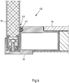
- connection 45 between the side wall panel 13 and the bottom 14 of the body 2 is shown.
- the attachment 18 is elongated in this case formed and forms a complementary lateral stop 46, on which the side wall panel 13 is supported on a sealing element 47.
- the connection 47 between the rear wall frame member 49 and the iswandpaneel 13 comes without another connection profile.
- the side wall panel 13 adjacent to the rear wall frame 8 still has a connection profile 16 according to the type of in the Fig. 2A-B illustrated connection profile 16 of the panel 13.
- the joining of the side wall panel 13 and the attachment 18 of the rear wall frame member 49 is carried out by gluing the attachment 18 with the outside of the side wall panel 13.
Landscapes
- Engineering & Computer Science (AREA)
- Chemical & Material Sciences (AREA)
- Combustion & Propulsion (AREA)
- Transportation (AREA)
- Mechanical Engineering (AREA)
- Physics & Mathematics (AREA)
- Thermal Sciences (AREA)
- Body Structure For Vehicles (AREA)
Abstract
Beschrieben und dargestellt ist ein Aufbau (2) eines Nutzfahrzeugs (1), insbesondere eines Lastkraftwagens, Anhängers oder Sattelaufliegers, mit wenigstens einem Paneel, vorzugsweise einem Stirnwandpaneel (11), einem Seitenwandpaneel (13) oder einem Dachpaneel (12), und mit wenigstens einem über eine Profilverbindung (15) mit dem Paneel verbundenen Anbauteil (18), vorzugsweise eines weiteren Paneels, eines Bodens (14) und/oder eines Rückwandrahmens (8), wobei die Profilverbindung (15) als Nut/Feder-Verbindung aus zwei korrespondierenden und miteinander verklebten Verbindungsprofilen (16,17) gebildet ist. Damit der Aufbau einfach, schnell und kostengünstig zu fertigen sowie langlebig und stabil ist, ist vorgesehen, dass die Profilverbindung (15) wenigstens zwei Nuten (23,28,33) und wenigstens zwei mit den wenigstens zwei Nuten (23,28,33) in Eingriff stehende Federn (24,26,32) aufweist.Described and illustrated is a structure (2) of a commercial vehicle (1), in particular a truck, trailer or semitrailer, with at least one panel, preferably a Stirnwandpaneel (11), a Seitenwandpaneel (13) or a Dachpaneel (12), and at least a via a profile connection (15) connected to the panel attachment (18), preferably another panel, a bottom (14) and / or a rear wall frame (8), wherein the profile connection (15) as a tongue and groove connection of two corresponding and bonded together connecting profiles (16,17) is formed. In order for the structure to be simple, quick and inexpensive to manufacture and durable and stable, it is provided that the profile connection (15) has at least two grooves (23, 28, 33) and at least two with the at least two grooves (23, 28, 33). has engaging springs (24,26,32).
Description
Die Erfindung betrifft einen Aufbau eines Nutzfahrzeugs, insbesondere eines Lastkraftwagens, Anhängers oder Sattelaufliegers, mit wenigstens einem Paneel, vorzugsweise einem Stirnwandpaneel, einem Seitenwandpaneel oder einem Dachpaneel, und mit wenigstens einem über eine Profilverbindung mit dem Paneel verbundenen Anbauteil, vorzugsweise eines weiteren Paneels, eines Bodens und/oder eines Rückwandrahmens, wobei die Profilverbindung als Nut/Feder-Verbindung aus zwei korrespondierenden und miteinander verklebten Verbindungsprofilen gebildet ist.The invention relates to a construction of a commercial vehicle, in particular a truck, trailer or semitrailer, with at least one panel, preferably a Stirnwandpaneel, a Seitenwandpaneel or Dachpaneel, and at least one connected via a profile connection to the panel attachment, preferably another panel, one Floor and / or a rear wall frame, wherein the profile connection is formed as a tongue and groove connection of two corresponding and glued together connection profiles.
Nutzfahrzeuge der vorgenannten Art können beispielsweise Lastkraftwagen, Anhänger und Sattelauflieger sein. Dabei sind die Nutzfahrzeuge insbesondere für den Transport von Gütern, wie Stückgütern, im öffentlichen Straßenverkehr vorgesehen. Zu diesem Zweck weisen die Nutzfahrzeuge unterschiedliche Arten von Aufbauten auf, welche Laderäume zur Aufnahme der zu transportierenden Güter bereitstellen. Es sind beispielsweise sogenannte Planenaufbauten bekannt, welche wenigstens eine Plane zum Verschließen wenigstens einer Seite und/oder des Dachs des Planenaufbaus aufweisen. Wenn die Plane entlang der Seitenwand verschoben werden kann, spricht man auch von sogenannten Curtainsidern.Commercial vehicles of the aforementioned type may be, for example, trucks, trailers and semitrailers. The commercial vehicles are intended in particular for the transport of goods, such as general cargo, on public roads. For this purpose, the commercial vehicles on different types of structures, which provide holds for receiving the goods to be transported. For example, so-called tarpaulin structures are known, which have at least one tarpaulin for closing at least one side and / or the roof of the tarpaulin structure. If the tarpaulin can be moved along the side wall, one also speaks of so-called curtainsiders.
Bei sogenannten Kofferaufbauten sind dagegen die Seitenwände und das Dach durch feste Wände verschlossen. Auch die Stirnwand ist bei Kofferaufbauten typischerweise als feste Wand ausgebildet, während die Rückwand meist aus zwei Flügeltüren, einem Rolltor oder dergleichen gebildet wird, um den Kofferaufbau von hinten beladen zu können. Die Seitenwände, das Dach und die Stirnwand von Kofferaufbauten sind in der Regel in Form von mehrschichtigen Paneelen aufgebaut, die eine innere strukturgebende Decklage, eine äußere strukturgebende Decklage und eine Kernlage aus einem geschäumten Kunststoff umfassen. Die Decklagen können selbst jeweils mehrlagig ausgebildet sein und dienen der Aussteifung der Paneele, weshalb die Decklagen meist wenigstens eine Schicht aus einem Metall und/oder einem faserverstärkten Kunststoff aufweisen. Da die Kofferaufbauten geschlossen sind und infolge des geschäumten Kunststoffs eine hohe thermische Isolation bereitstellen, sind Kofferaufbauten in besonderem Maße für den Transport von feuchtigkeitsempfindlichen und/oder temperaturempfindlichen Gütern, also beispielsweise für den sogenannten Trockentransport und/oder den Kühltransport geeignet.In so-called box bodies, however, the side walls and the roof are closed by solid walls. Also, the end wall is typically designed as a solid wall in box bodies, while the rear wall is usually formed of two wing doors, a roller shutter or the like to load the box body from the rear can. The side walls, the roof and the end wall of box bodies are usually constructed in the form of multi-layer panels comprising an inner structural cover layer, an outer structural cover layer and a core layer of a foamed plastic. The cover layers can each themselves be formed multi-layered and serve to stiffen the panels, which is why the cover layers usually have at least one layer of a metal and / or a fiber-reinforced plastic. Since the box bodies are closed and provide a high thermal insulation due to the foamed plastic, box bodies are particularly suitable for the transport of moisture-sensitive and / or temperature-sensitive goods, so for example for the so-called dry transport and / or refrigerated transport.
Die einzelnen Paneele müssen zur Bildung eines Kofferaufbaus mit anderen Paneelen und Anbauteilen verbunden werden, wobei es sich bei den Anbauteilen um Teile eines Rückwandrahmens, Teile des Bodens oder aber mit einem weiteren Paneel verbundene Anschlussteile handeln kann. Es kann auch vorgesehen sein, dass die Seitenwände, das Dach und/oder die Stirnwand aus mehreren Paneelen zusammengesetzt werden. Dann bedarf es einer Verbindung der einzelnen Paneele einer Wand oder des Dachs untereinander, wobei ebenfalls ein Paneel über eine entsprechende Profilverbindung mit einem Anbauteil eines anderen Paneels verbunden werden kann, wobei das andere Paneel Teil derselben Wand oder desselben Dachs sein kann aber nicht muss.The individual panels must be connected to form a box body with other panels and attachments, which may be parts of a back frame, parts of the floor or connected to another panel connecting parts in the attachments. It can also be provided that the side walls, the roof and / or the end wall are composed of several panels. Then it requires a connection of the individual panels of a wall or of the roof with each other, wherein also a panel can be connected via a corresponding profile connection with an attachment of another panel, the other panel may be part of the same wall or the same roof but not necessarily.
Für die zuvor genannten Verbindungen eines Aufbaus, insbesondere eines Kofferaufbaus, eines Nutzfahrzeugs sind bereits unterschiedliche Verbindungen bekannt. So werden teilweise Profilverbindungen eingesetzt, die als Nut/Feder-Verbindung aus zwei korrespondierenden Verbindungsprofilen gebildet werden. Durch die korrespondierend ausgebildeten Nuten und Federn wird das positionsgenaue Fügen der Profilverbindungen vereinfacht. Zudem können die Verbindungsprofile der Profilverbindungen noch miteinander verklebt werden, um einer dauerhafte Verbindung zu erhalten.For the aforementioned compounds of a structure, in particular a box body, a commercial vehicle different compounds are already known. Thus, partially profile connections are used, which are formed as a tongue and groove connection of two corresponding connection profiles. Due to the correspondingly shaped grooves and springs, the positionally accurate joining of the profile connections is simplified. In addition, the connection profiles of the profile connections can still be glued together to obtain a permanent connection.
Grundsätzlich sollen die Profilverbindungen möglichst einfach und schnell gefügt werden können. Gleichzeitig sollen die Verbindungsprofile kostengünstig hergestellt werden und hohe Kräfte übertragen können. Nicht zuletzt müssen die Profilverbindungen eine ausreichende Flexibilität zulassen, damit übliche Verwindungen des Aufbaus oder dergleichen nicht zu einer Beschädigung des Aufbau bzw. der Profilverbindung führen. Diesem Anforderungsprofil genügen die bekannten Profilverbindungen noch nicht zufriedenstellend, so dass diesbezüglich weiter Optimierungsbedarf besteht.In principle, the profile connections should be able to be joined as easily and quickly as possible. At the same time, the connection profiles are produced inexpensively be able to transmit high forces. Last but not least, the profile connections must allow sufficient flexibility so that normal twisting of the structure or the like does not lead to damage to the structure or the profile connection. This requirement profile, the known profile connections are not yet satisfactory, so that further optimization is required in this regard.
Daher liegt der vorliegenden Erfindung die Aufgabe zugrunde, den eingangs genannten und zuvor näher erläuterten Aufbau derart auszugestalten und weiterzubilden, dass er einfach, schnell und kostengünstig zu fertigen sowie langlebig und stabil ist.Therefore, the present invention seeks to design the above-mentioned and previously explained construction in such a way and further that it is simple, fast and inexpensive to manufacture and durable and stable.
Diese Aufgabe ist bei einem Aufbau nach dem Oberbegriff von Anspruch 1 dadurch gelöst, dass die Profilverbindung wenigstens zwei Nuten und wenigstens zwei mit den wenigstens zwei Nuten in Eingriff stehende Federn aufweist.This object is achieved in a structure according to the preamble of
Durch diese Ausgestaltung wird eine zuverlässigere Profilverbindung geschaffen, die sich dennoch sehr einfach und positionsgenau fügen lässt. Es greifen nämlich wenigstens zwei Federn in wenigstens zwei Nuten. Mithin wird eine wenigstens doppelte Verbindung und eine wenigstens doppelte Positionierung erreicht. Zudem wird die Profilverbindung noch verstärkt, weil die in die zwei Nuten eingreifenden Federn großflächige Verbindungsbereiche bzw. umfangreiche Verbindungsflächen bereitstellen, die sich für das Verkleben der Verbindungsprofile untereinander nutzen lassen. Dennoch können die Verbindungsprofile sehr einfach gefertigt und miteinander verbunden werden, was sich günstig auf die Fertigungskosten des Aufbaus insgesamt auswirkt. Dabei sind insbesondere die Fertigungskosten von Aufbauten, insbesondere Kofferaufbauten, von Nutzfahrzeugen, etwa in Form von Lastkraftwagen, mit einem zulässigen Gesamtgewicht zwischen etwa 3 und 6 Tonnen von besonderer Bedeutung. Entsprechende Nutzfahrzeuge werden auch als Lieferwagen oder Zustellfahrzeuge bezeichnet, da diese oft zum Liefern von Gütern oder Sendungen an mehrere Endkunden, und zwar bedarfsweise gewerbliche als auch private Endkunden genutzt werden. Bei Nutzfahrzeugen, die motorisch angetrieben und direkt mit dem Aufbau versehen sind, besteht für Hersteller ein sehr erheblicher Kostendruck, auf den die Profilverbindungen einen nicht unerheblichen Einfluss haben. Bei Anhängern oder Sattelaufliegern kommen noch weitere Kostenfaktoren hinzu, die den Einfluss der Profilverbindung auf die Fertigungskosten des Nutzfahrzeugs bzw. Aufbaus mindern können.By this configuration, a more reliable profile connection is created, which can still be very simple and accurate position paste. Namely, at least two springs engage in at least two grooves. Thus, at least a double connection and at least a double positioning is achieved. In addition, the profile connection is reinforced because the engaging in the two grooves springs provide large-area connection areas or extensive connection surfaces that can be used for bonding the connection profiles with each other. Nevertheless, the connection profiles can be very easily manufactured and connected to each other, which has a favorable effect on the manufacturing costs of the structure as a whole. In particular, the manufacturing costs of structures, in particular box bodies, of commercial vehicles, such as in the form of trucks, with a gross vehicle weight of between about 3 and 6 tons are of particular importance. Corresponding commercial vehicles are also referred to as vans or delivery vehicles, as these often for delivering goods or shipments to several end customers, and if necessary, commercial as well private end customers are used. For commercial vehicles, which are powered by a motor and directly provided with the structure, there is a very considerable cost pressure for manufacturers, to which the profile connections have a not inconsiderable influence. For trailers or semi-trailers, additional cost factors are added that can reduce the influence of the profile connection on the cost of production of the commercial vehicle or body.
Bei der Profilverbindung kann der Einfachheit halber ein Verbindungsprofil die wenigstens zwei Nuten und das korrespondierende Verbindungsprofil die korrespondierenden wenigstens zwei Federn aufweisen. Allerdings ist es aus konstruktiver Sicht, insbesondere zur Verringerung des Platzbedarfs für die Verbindung, günstig, wenn wenigstens ein Verbindungsprofil, insbesondere aber beide Verbindungsprofile einer Profilverbindung sowohl wenigstens eine Feder als auch wenigstens eine Nut aufweisen. So können beispielsweise Nutflanken einerseits eine Nut definieren und andererseits als Feder in eine gegenüberliegende Nut des angrenzenden Verbindungsprofils eingreifen. Dabei gilt grundsätzlich, dass die Profilverbindung umso fester sein kann, je effizienter die Profilverbindung den für die Verbindung zur Verfügung stehenden Raum ausnutzt.In the case of the profile connection, for the sake of simplicity, a connection profile may have the at least two grooves and the corresponding connection profile the corresponding at least two springs. However, it is favorable from a constructive point of view, in particular for reducing the space required for the connection, if at least one connection profile, but in particular both connection profiles of a profile connection, have both at least one spring and at least one groove. Thus, for example, groove flanks on the one hand define a groove and on the other hand engage as spring in an opposite groove of the adjacent connection profile. It basically applies that the profile connection can be the firmer, the more efficient the profile connection makes use of the space available for the connection.
Bei einer ersten bevorzugten Ausgestaltung des Aufbaus sind die wenigstens zwei Nuten wenigstens teilweise mit einem Klebstoff ausgefüllt und mit den jeweils in die Nuten eingreifenden Federn verklebt. Auf diese Weise wird ein zuverlässiger und langlebiger Stoffschluss zwischen den Verbindungsprofilen erreicht, der zugleich in der Lage ist, sehr hohe Kräfte zu übertragen. Als besonders effektiv und zweckmäßig hat es sich ergeben, wenn sich der Klebstoff zusammenhängend von wenigstens einer Nut bis in wenigstens eine andere Nut erstreckt. Dies vergrößert die miteinander verklebten Flächen und kann zudem das Einbringen des Klebstoffs vereinfachen. Der Klebstoff kann beispielsweise an nur einer Stelle, beispielsweise in nur einer Nut vorgesehen sein und beim Fügen der Profilverbindung dann bis in wenigstens eine andere Nut der Profilverbindung gelangen, etwa weil der Klebstoff durch das Eingreifen einer Feder in die den Klebstoff aufweisende Nut verdrängt und so in eine angrenzende Nut gedrückt wird. Dabei gehören vorzugsweise die über den Klebstoff direkt miteinander verbundenen Nuten zu einem Verbindungsprofil der Profilverbindung, um eine umfangreiche und effektive stoffschlüssige Verbindung innerhalb der Profilverbindung bereitstellen zu können. Gleichzeitig kann es zur Vereinfachung des Aufbringens und der Verteilung des Klebstoffs in der Profilverbindung jedoch bevorzugt sein, wenn sich der Klebstoff von einer Nut des einen Verbindungsprofils in eine Nut des anderen Verbindungsprofils erstreckt. Dann steht zudem vorzugsweise noch die Nut des anderen Verbindungsprofils für die Bereitstellung der stoffschlüssigen Verbindung zur Verfügung.In a first preferred embodiment of the structure, the at least two grooves are at least partially filled with an adhesive and glued to the respectively engaging in the grooves springs. In this way, a reliable and durable material connection between the connection profiles is achieved, which is at the same time able to transmit very high forces. It has proven to be particularly effective and expedient if the adhesive extends continuously from at least one groove to at least one other groove. This increases the surfaces glued together and can also simplify the introduction of the adhesive. The adhesive may for example be provided at only one point, for example, in only one groove and then enter into at least one other groove of the profile connection when joining the profile connection, such as the adhesive displaced by the engagement of a spring in the groove having the adhesive and so in a adjacent groove is pressed. In this case, the grooves directly connected to one another via the adhesive preferably belong to a connection profile of the profile connection in order to be able to provide a comprehensive and effective cohesive connection within the profile connection. At the same time, however, to simplify the application and distribution of the adhesive in the profile connection, it may be preferable for the adhesive to extend from a groove of one connection profile to a groove in the other connection profile. Then also preferably still the groove of the other connection profile for the provision of cohesive connection is available.
Um die Profilverbindung weiter zu verstärken und/oder um die Profilverbindung vor dem vollständigen Aushärten des Klebstoffs sicher zusammen zu halten, etwa während eines weiteren, nachfolgenden Fertigungsschritts, kann die Profilverbindung wenigstens eine Rastverbindung zwischen den Verbindungsprofilen aufweisen. Um eine platzsparende Profilverbindung bereitstellen zu können, wird die Rastverbindung vorzugsweise zwischen wenigstens einer Nut und einer in die wenigstens eine Nut eingreifenden Feder gebildet. So können für einzelne Abschnitte der Profilverbindung doppelte oder mehrfache Funktionalitäten bereitgestellt werden, ohne diese Funktionalitäten bzw. Verbindungen nebeneinander vorsehen zu müssen. Die vorstehenden Vorteile werden insbesondere auch dann erreicht, wenn die Rastverbindung zwischen beiden Nutflanken wenigstens einer Nut und der in diese Nut eingreifenden Feder vorgesehen ist.In order to further strengthen the profile connection and / or to securely hold together the profile connection prior to complete curing of the adhesive, such as during a further, subsequent manufacturing step, the profile connection may comprise at least one latching connection between the connection profiles. In order to provide a space-saving profile connection, the latching connection is preferably formed between at least one groove and an engaging in the at least one groove spring. Thus, duplicate or multiple functionalities can be provided for individual sections of the profile connection without having to provide these functionalities or connections side by side. The above advantages are achieved in particular even if the latching connection between the two groove flanks of at least one groove and the tongue engaging in this groove is provided.
Die Nut/Feder-Verbindung der Verbindungsprofile kann vorzugsweise so ausgebildet werden, dass die Verbindungsprofile nicht exakt bis zu einem bestimmten Maß oder Umfang ineinander geschoben werden müssen. Vielmehr kann vorgesehen sein, dass die Verbindungsprofile auch in unterschiedlich weit eingeschobener Stellung eine dauerhafte und feste Verbindung bereitstellen. Auf diese Weise kann beispielsweise ein Toleranzausgleich für die Verbindung bereitgestellt werden. Dabei ist es besonders bevorzugt, wenn die Nut/Feder-Verbindung als Rastverbindung ausgebildet ist und/oder die Verbindungsprofile stoffschlüssig über einen Klebstoff verbunden, respektive verklebt, sind. Dann kommt es nicht so sehr darauf an, wie weit die Verbindungsprofile ineinandergeschoben sind. Zu diesem Zweck ist es weiter bevorzugt, wenn die Rastverbindung mehrere Rastvorsprünge derart aufweist, dass sich bei unterschiedlich weit ineinander geschobenen Verbindungsprofilen unterschiedliche Rastvorsprünge hintergreifen. Dies kann dazu führen, dass je nachdem wie weit die Verbindungsprofile ineinander geschoben sind, einzelne Rastvorsprünge nicht aktiv an der Bildung einer Rastverbindung beteiligt sind. Diese könnten aber an der Bildung der Rastverbindung beteiligt sein, wenn die Verbindungsprofile weiter oder weniger weit ineinander geschoben wären.The tongue and groove connection of the connection profiles can preferably be formed so that the connection profiles do not have to be pushed into each other exactly to a certain extent or extent. Rather, it can be provided that the connection profiles provide a permanent and firm connection in different far inserted position. In this way, for example, a tolerance compensation for the connection can be provided. It is particularly preferred if the groove / tongue connection is designed as a latching connection and / or the connection profiles cohesively via an adhesive connected, respectively glued, are. Then it does not matter how much the connection profiles are pushed together. For this purpose, it is further preferred if the latching connection has a plurality of latching projections in such a way that different latching projections engage behind each other when the connecting profiles are pushed into each other to different extents. This can lead to depending on how far the connection profiles are pushed into each other, individual locking projections are not actively involved in the formation of a locking connection. However, these could be involved in the formation of the locking connection, if the connection profiles would be further or less pushed into each other.
Um die stoffschlüssige und/oder die Rastverbindung zwischen den Verbindungsprofilen der Profilverbindung zu verstärken und/oder zu bilden, kann wenigstens eine Feder wenigstens zwei Federabschnitte aufweisen. Diese Federabschnitte sind dabei insbesondere jeweils gegenüberliegenden Nutflanken zugeordnet. Ferner sind die Federabschnitte beispielsweise flexibel und/oder verstellbar vorgesehen. Die Federabschnitte lassen sich so gegeneinander in Richtung der zugeordneten Nutflanken verstellen. Die Federabschnitte können dabei der Einfachheit halber aufgrund einer Rückstellkraft infolge einer Verformung oder Vorspannung der Federabschnitte in Richtung der zugehörigen Nutflanken drücken. Beispielweise kann die wenigstens eine Feder so breit vorgesehen sein, dass sie nur unter Zusammendrücken der Federabschnitte in die korrespondierende Nut eingeführt werden kann. In der Nut drücken die Federabschnitte dann wieder infolge der aus der entsprechenden Verformung der Feder beim Eingreifen in die Nut resultierenden Rückstellkraft nach außen in Richtung der zugehörigen Nutflanken. Alternativ oder zusätzlich kann aber auch wenigstens ein Fremdelement zwischen die Federabschnitte gebracht, insbesondere eingeschoben, werden, so dass die Federabschnitte unter Aufweitung der Feder in Richtung der gegenüberliegenden Nutflanken auseinander gedrückt, mithin gegeneinander in Richtung der jeweils zugeordneten Nutzflanken verstellt werden.In order to reinforce and / or form the cohesive and / or latching connection between the connection profiles of the profile connection, at least one spring can have at least two spring sections. These spring sections are assigned in particular each opposite groove flanks. Furthermore, the spring sections are provided, for example, flexible and / or adjustable. The spring sections can thus be adjusted against each other in the direction of the associated groove flanks. For the sake of simplicity, the spring sections can press in the direction of the associated groove flanks due to a restoring force as a result of deformation or pretensioning of the spring sections. For example, the at least one spring can be provided so wide that it can be inserted only by compressing the spring sections in the corresponding groove. In the groove, the spring sections then press again as a result of the resulting from the corresponding deformation of the spring upon engagement with the restoring force in the direction of the associated groove flanks. Alternatively or additionally, however, at least one foreign element may be brought between the spring sections, in particular pushed in, so that the spring sections are pressed apart in the direction of the opposite groove flanks by widening of the spring, thus being adjusted against one another in the direction of the respective associated flanks.
Besonders vorteilhaft hat sich der Einsatz der Profilverbindung in Kombination mit Paneelen erwiesen, die wenigstens zwei äußere strukturgebende Decklagen aufweisen, diese lassen sich zweckmäßig mit einem Verbindungsprofil versehen und zudem leicht mit Anbauteilen verbinden. Die Decklagen können dabei jeweils als Strukturlage ausgebildet sein oder eine Strukturlage umfassen, um dem Paneel die nötige Steifigkeit zu verleihen. Als Strukturlage kommt dabei insbesondere eine Lage aus Kunststoff, faserverstärktem Kunststoff, Stahl oder Aluminium in Frage, da diese Materialen die benötigten Eigenschaften bereitstellen und erschwinglich sind. Die Decklagen können aber bedarfsweise noch weitere Schichten aufweisen, die beispielsweise der Anbindung einer Decklage, dem Schutz der Strukturlage und/oder dem optisch ansprechenden Abschluss der Decklage nach außen dienen können. Alternativ oder zusätzlich zur Ausgestaltung der äußeren Decklagen ist es bevorzugt, wenn zwischen den Decklagen eine Kernlage aus einem, insbesondere geschäumten, Kunststoff vorgesehen ist. Derartige Kernlagen sind fest und gleichzeitig leicht.Particularly advantageous is the use of the profile connection in combination with Paneels proved that have at least two outer structural cover layers, these can be conveniently provided with a connection profile and also easily connect with attachments. The cover layers can each be formed as a structural layer or comprise a structural layer in order to give the panel the necessary rigidity. In particular, a layer of plastic, fiber-reinforced plastic, steel or aluminum is considered as a structural layer, since these materials provide the required properties and are affordable. If required, however, the cover layers can also have further layers which can serve, for example, the connection of a cover layer, the protection of the structural layer and / or the visually appealing completion of the cover layer to the outside. As an alternative or in addition to the embodiment of the outer cover layers, it is preferred if between the cover layers a core layer of a, in particular foamed, plastic is provided. Such core layers are firm and lightweight at the same time.
Um ein Verbindungsprofil fest mit dem Paneel zu verbinden und/oder die entsprechende Schmalseite des Paneels, etwa zum Schutz der Kernlage, zu verschließen, kann ein Verbindungsprofil der Profilverbindung zwei Längsseiten aufweisen, die einander gegenüberliegend angeordnet sind und jeweils bezogen auf das Verbindungsprofil nach außen weisen. Diese Längsseiten können dann jeweils mit einer äußeren Decklage des Paneels verbunden, vorzugsweise verklebt, sein. So wird ein langlebiger Abschluss des Paneels, bedarfsweise über die gesamte Breite der Schmalseite, erreicht und zudem eine feste und dauerhafte Anbindung des Verbindungsprofils an die Decklagen bzw. das Paneel bereitgestellt.In order to firmly connect a connection profile to the panel and / or to close the corresponding narrow side of the panel, for example to protect the core layer, a connection profile of the profile connection can have two longitudinal sides, which are arranged opposite to one another and face outwards relative to the connection profile , These longitudinal sides can then each connected to an outer cover layer of the panel, preferably glued be. Thus, a long-lasting completion of the panel, if necessary, over the entire width of the narrow side, achieved and also provided a firm and permanent connection of the connection profile to the cover layers or the panel.
Um den Abschluss der entsprechenden Schmalseite des Paneels noch zu verbessern oder um die positionsgenaue Montage des Verbindungsprofils am Paneel in einfacher Weise sicherzustellen, kann ein Verbindungsprofil der Profilverbindung an zwei einander gegenüberliegenden, nach außen weisenden bzw. äußeren Längsseiten jeweils einen Anschlag zur Anlage an ein freies Ende einer Decklage des Paneels aufweisen. So kann beispielsweise das Verbindungsprofil von außen auf die Decklagen aufgeschoben werden oder die Decklagen positionsgenau auf bzw. an dem Verbindungsprofil vorgesehen werden.In order to improve the completion of the corresponding narrow side of the panel or to ensure the positionally accurate mounting of the connection profile on the panel in a simple manner, a connection profile of the profile connection on two opposite, outwardly facing or outer longitudinal sides each have a stop for engagement with a free Have end of a cover layer of the panel. For example, the connection profile from the outside on the cover layers be postponed or the cover layers are accurately positioned on or on the connection profile.
Alternativ oder zusätzlich kann ein Verbindungsprofil der Profilverbindung an zwei einander gegenüberliegenden äußeren Längsseiten jeweils eine Rippe aufweisen. Die Rippen können das Paneel außen umgreifen. So wird ein schmutz- und feuchtigkeitsabweisender Abschluss der Profilverbindung erreicht. Um eine hohe Funktionalität der Profilverbindung auf geringem Raum bereitzustellen, können die Rippen durch Nutflanken ausgebildet sein. Den Rippen kann so eine Doppelfunktion verliehen werden, um eine hochintegrative Profilverbindung bereitzustellen.Alternatively or additionally, a connection profile of the profile connection on two opposite outer longitudinal sides each have a rib. The ribs can embrace the panel on the outside. So a dirt and moisture repellent completion of the profile connection is achieved. In order to provide a high functionality of the profile connection in a small space, the ribs may be formed by groove flanks. The ribs can thus be given a dual function in order to provide a highly integrative profile connection.
Um eine feste Verbindung zwischen dem Paneel und dem wenigstens einen Verbindungsprofil der Profilverbindung zu etablieren, kann es zweckmäßig sein, wenn das Verbindungsprofil eine zur gegenüberliegenden Schmalseite des Paneels offene Aufnahme aufweist. Die Aufnahme ist dann zugänglich für den geschäumten Kunststoff aus der Kernlage. Geschäumter Kunststoff, der gegebenenfalls überschüssig ist, kann also beim Ausschäumen des Paneels in der Aufnahme aufgenommen werden. Ferner kann die Aufnahme noch wenigstens eine Hinterschneidung aufweisen, die gesehen von der gegenüberliegenden Schmalseite einen Hinterschnitt bereitstellt. Weiter bevorzugt ist es dabei, wenn an beiden Seiten der Aufnahme eine solche Hinterschneidung vorgesehen ist. Der die Kernlage des Paneels bildende, geschäumte Kunststoff kann sich dann bis in die Aufnahme hinein erstrecken und die wenigstens eine Hinterschneidung formschlüssig hintergreifen. Nach dem Aushärten des geschäumten Kunststoffs, entsteht so ein Formschluss zwischen der Kernlage bzw. dem Material der Kernlage und dem Verbindungsprofil.In order to establish a fixed connection between the panel and the at least one connection profile of the profile connection, it may be expedient if the connection profile has an open to the opposite narrow side of the panel receptacle. The receptacle is then accessible to the foamed plastic from the core layer. Foamed plastic, which may be excess, can therefore be taken up during foaming of the panel in the recording. Furthermore, the receptacle can also have at least one undercut, which provides an undercut as seen from the opposite narrow side. It is further preferred if such an undercut is provided on both sides of the receptacle. The foamed plastic forming the core layer of the panel can then extend into the receptacle and engage behind the at least one undercut in a form-fitting manner. After curing of the foamed plastic, so creates a positive connection between the core layer and the material of the core layer and the connection profile.
Zur Abdichtung der Profilverbindung kann diese ein Dichtelement aufweisen. Dabei bietet es sich der Einfachheit halber an, wenn das Dichtelement in wenigstens einer, insbesondere einer bezogen auf den Aufbau äußeren, Nut wenigstens eines Verbindungsprofils vorgesehen ist und dort einen Spalt zwischen der Nut und einer in die Nut eingreifenden korrespondierenden Feder abdichtet. Dabei wird eine besonders zuverlässige Abdichtung erreicht, wenn das Dichtelement zwischen einem freien Ende der Feder und dem Nutgrund der zugehörigen Nut angeordnet ist. Das Dichtelement kann der Einfachheit halber aus einem elastischen Kunststoff oder Gummi bestehen.To seal the profile connection, this may have a sealing element. For reasons of simplicity, it is useful if the sealing element is provided in at least one groove, in particular a groove of at least one connecting profile, and seals a gap between the groove and a corresponding spring engaging in the groove. There will be a Particularly reliable sealing achieved when the sealing element between a free end of the spring and the groove bottom of the associated groove is arranged. The sealing element may consist of an elastic plastic or rubber for the sake of simplicity.
Um die Paneelherstellung zu vereinfachen und zu beschleunigen, bietet es sich an, das Paneel nach dem Einbringen des wenigstens einen Verbindungsprofils zwischen die Decklagen auszuschäumen. Dabei muss dann aber die durch den geschäumten Kunststoff verdrängte Luft aus dem Paneel entweichen. Zu diesem Zweck kann das wenigstens eine Verbindungsprofil wenigstens einen sich in Längsrichtung des Verbindungsprofils erstreckenden und an wenigstens einem Längsende des Verbindungsprofils offenen Entlüftungskanal aufweisen. Über diesen Entlüftungskanal kann die beim Ausschäumen im inneren des Paneels verdrängte Luft nach außen abgeführt werden. Damit die verdrängte Luft auch problemlos in den Entlüftungskanal gelangen und darin abströmen kann, bietet es sich weiter an, wenn der Entlüftungskanal zwischen den Längsenden des Verbindungsprofils wenigstens eine weitere Öffnung aufweist, die aus dem Entlüftungskanal zum Inneren des Paneels hin gerichtet ist. Die Öffnung bildet dann wenigstens während des Ausschäumens des Paneels eine Verbindung zwischen der Luft im inneren des Paneels und im inneren des Entlüftungskanals des wenigstens einen Verbindungsprofils.In order to simplify and accelerate the panel production, it is advisable to foam the panel after the introduction of the at least one connecting profile between the cover layers. But then the air displaced by the foamed plastic must escape from the panel. For this purpose, the at least one connection profile may have at least one ventilation channel extending in the longitudinal direction of the connection profile and open at at least one longitudinal end of the connection profile. About this vent channel displaced during foaming inside the panel air can be discharged to the outside. Thus, the displaced air can easily enter the vent channel and can flow into it, it continues to offer, when the vent channel between the longitudinal ends of the connection profile has at least one further opening which is directed from the vent channel to the interior of the panel. The opening then forms, at least during the foaming of the panel, a connection between the air in the interior of the panel and in the interior of the ventilation channel of the at least one connecting profile.
Die Herstellung des Paneels und/oder des Aufbaus kann auch dadurch vereinfacht werden, dass das wenigstens eine Verbindungsprofil wenigstens im Wesentlichen symmetrisch zu einer Ebene parallel zum Paneel ausgebildet ist. Dann spielt es für die Montage grundsätzlich keine Rolle, wenn die Längsenden des Verbindungsprofils etwa bei der Fertigung des Paneels vertauscht worden sind. Hierauf muss also nicht geachtet werden und es wird so die Bildung von Ausschuss verringert.The manufacture of the panel and / or the structure can also be simplified in that the at least one connecting profile is at least substantially symmetrical to a plane parallel to the panel. In that case, it is basically of no importance for the mounting when the longitudinal ends of the connection profile have been interchanged, for example during the production of the panel. So this does not need to be respected and it will reduce the formation of waste.
Um für einen Toleranzausgleich beim Bilden eines Paneels in einer Richtung senkrecht zum Paneel zu sorgen, bietet es sich an, wenn das Verbindungsprofil zwischen zwei Decklagen in einer Richtung senkrecht zum Paneel zusammengedrückt werden kann. Um dies zu erreichen, können einander gegenüberliegende, nach außen weisende Längsseiten des Verbindungsprofils über wenigstens ein Scharnierelement, wenigstens einen sich in einem Winkel von maximal 80°, vorzugsweise wenigstens 70°, zu einer Ebene parallel zum Paneel erstreckenden Steg und/oder durch wenigstens einen gebogenen Steg miteinander verbunden sei. Bedarfsweise wird das Scharnierelement durch wenigstens einen der Stege der vorgenannten Art gebildet. Das wenigstens eine Scharnierelement bzw. der wenigstens eine Steg können sich dann verstellen, wenn ein hinreichender Druck von außen senkrecht zum Paneel auf das Verbindungsprofil ausgeübt wird. Besonders zweckmäßig kann es sein, wenn das wenigstens eine Scharnierelement durch zwei Stege gebildet wird, die in einem Winkel von maximal 80°, vorzugsweise wenigstens 70°, bezogen auf eine Ebene parallel zum Paneel V-förmig aufeinander stoßen. Alternativ oder zusätzlich können zwei Scharnierelemente bedarfsweise einen Entlüftungskanal begrenzen und/oder bilden.In order to provide a tolerance compensation when forming a panel in a direction perpendicular to the panel, it is convenient if the connection profile between two cover layers is compressed in a direction perpendicular to the panel can be. To achieve this, opposing, outwardly facing longitudinal sides of the connection profile via at least one hinge element, at least one at an angle of a maximum of 80 °, preferably at least 70 °, to a plane parallel to the panel extending web and / or by at least one curved web are interconnected. If necessary, the hinge element is formed by at least one of the webs of the aforementioned type. The at least one hinge element or the at least one web can then be adjusted if a sufficient pressure is exerted perpendicular to the panel on the connection profile from the outside. It may be particularly useful if the at least one hinge element is formed by two webs which abut one another at an angle of at most 80 °, preferably at least 70 °, with respect to a plane parallel to the panel in a V-shape. Alternatively or additionally, two hinge elements may, if necessary, limit and / or form a ventilation channel.
Für eine einfache und kostengünstige Herstellung der Verbindungsprofile kann es zweckmäßig sein, wenigstens ein Verbindungsprofil aus Kunststoff, insbesondere aus PVC, vorzugsweise als Extrusionsprofil, zu bilden. Alternativ oder zusätzlich kann aber auch wenigstens ein Verbindungsprofil aus Metall, insbesondere Stahl oder Aluminium gebildet werden. Im Regelfall wird die Verwendung von Kunststoff kostengünstiger sein, aber die Verwendung von Metall eine höhere Festigkeit und oder Steifigkeit bereitstellen.For a simple and cost-effective production of the connection profiles, it may be expedient to form at least one connecting profile made of plastic, in particular of PVC, preferably as an extrusion profile. Alternatively or additionally, however, at least one connecting profile made of metal, in particular steel or aluminum may be formed. As a rule, the use of plastic will be less expensive, but the use of metal will provide greater strength and or rigidity.
Um eine Vereinfachung bei der Herstellung des Aufbaus zu erreichen und die Vorteile der Profilverbindung möglichst umfassend nutzen zu können, kann wenigstens ein Paneel des Aufbaus an wenigstens zwei, vorzugsweise wenigstens drei, insbesondere vier, Schmalseiten jeweils ein Verbindungsprofil der zuvor beschriebenen Art zur Bildung der zuvor beschriebenen Profilverbindung aufweisen. Dabei kann es sich wenigstens teilweise um wenigstens im Wesentlichen gleichartige Verbindungsprofile und/oder wenigstens teilweise um korrespondierende Verbindungsprofile handeln. Die korrespondierenden Verbindungsprofile sind dabei insbesondere derart korrespondierend zueinander ausgebildet, dass die Verbindungsprofile grundsätzlich zur Bildung einer gemeinsamen Profilverbindung geeignet wären.In order to achieve a simplification in the production of the structure and to use the advantages of profile connection as possible, at least one panel of the structure at least two, preferably at least three, in particular four, narrow sides each have a connection profile of the type described above to form the previously have described profile connection. These may be at least partially at least substantially similar connection profiles and / or at least partially to corresponding connection profiles. The corresponding connection profiles are included in particular designed to correspond to one another in such a way that the connection profiles would in principle be suitable for forming a common profile connection.
Nachfolgend wird die Erfindung anhand einer lediglich Ausführungsbeispiele darstellenden Zeichnung näher erläutert. In der Zeichnung zeigt
- Fig. 1
- ein Nutzfahrzeug mit einem erfindungsgemäßen Aufbau in einer perspektivischen Ansicht,
- Fig. 2A-B
- eine Profilverbindung des Aufbaus gemäß
Fig. 1 in einer Schnittdarstellung, - Fig. 3
- die Verbindung zwischen einem Seitenwandpaneel und dem Dach des Aufbaus gemäß
Fig. 1 mit der Profilverbindung gemäßFig. 2A in einer Schnittdarstellung, - Fig. 4
- die Verbindung zwischen einem Seitenwandpaneel und dem Boden des Aufbaus gemäß
Fig. 1 mit der Profilverbindung gemäßFig. 2A in einer Schnittdarstellung und - Fig. 5
- die Verbindung zwischen einem Seitenwandpaneel und einem Rückwandrahmenelement des Aufbaus gemäß
Fig. 1 in einer Schnittdarstellung,
- Fig. 1
- a commercial vehicle with a construction according to the invention in a perspective view,
- Fig. 2A-B
- a profile connection of the structure according to
Fig. 1 in a sectional view, - Fig. 3
- the connection between a side wall panel and the roof of the structure according to
Fig. 1 with the profile connection according toFig. 2A in a sectional view, - Fig. 4
- the connection between a Seitenwandpaneel and the bottom of the structure according to
Fig. 1 with the profile connection according toFig. 2A in a sectional view and - Fig. 5
- the connection between a side wall panel and a rear wall frame member of the structure according to
Fig. 1 in a sectional view,
In der
Zur Verbindung der Seitenwände 4 mit dem Dach 5, der Stirnwand 3 und dem Boden 14 dienen bei dem dargestellten und insoweit bevorzugten Aufbau 2 Profilverbindungen 15. Die Profilverbindung 15 zwischen der Seitenwand 3 und entweder dem Dach 5 oder der Stirnwand 4, die beim dargestellten und insoweit bevorzugten Aufbau 2 einander entsprechen, ist in der
Zudem kann das Anbauteil 18 auch ein Element eines angrenzenden Paneels sein, also beispielsweise ebenfalls wenigstens teilweise in dem angrenzenden Paneel aufgenommen sein. Dies ist insbesondere dann der Fall, wenn die über die Profilverbindung 15 verbundenen Paneele in einer gemeinsamen Ebene angeordnet sind, also bedarfsweise zusammen wenigstens einen Teil einer Seitenwand 4, der Stirnwand 3 und/oder des Dachs 5 bilden. Anbauteile 18 im Sinne eines Adapters kommen insbesondere, aber weder ausschließlich noch zwingend, zur Verbindung separater Paneele, insbesondere über Eck, also beispielsweise zum Verbinden einer Seitenwand 4 mit der Stirnwand 3 oder dem Dach 5, in Frage.In addition, the
Vor diesem Hintergrund wird der besseren Verständlichkeit halber und zur Vermeidung unnötiger Wiederholungen weiter zwischen dem Paneel 13 und dem Anbauteil 18 unterschieden, auch wenn das Anbauteil 18 bedarfsweise als Teil eines angrenzenden Paneels verstanden werden kann. Hinzukommt, dass die Unterscheidung zwischen dem Verbindungsprofil 16 des Paneels 13 und dem Verbindungsprofil 17 des Anbauteils 18 nicht zwingend in der beschriebenen Weise zu erfolgen hat. Die Zuordnung der Verbindungsprofile 16,17 könnten auch untereinander getauscht sein, auch wenn die in der
Das Verbindungsprofil 16 des Paneels 13 ist, wie in der
Im Querschnitt des Verbindungsprofils 16 zwischen den beiden Decklagen 9 des Paneels 13 weist das Verbindungsprofil 16 zwei Nuten 13 auf, in die jeweils eine Feder 24 des korrespondierenden Verbindungsprofils 17 des Anbauteils 18 eingreift. Die die Anschläge 21 bildenden Nasen 22 sind dabei im Endbereich jeweils einer Nutflanke 25 vorgesehen.In the cross section of the
Zwischen den Nuten 23 des Verbindungsprofils 16 des Paneels 13 ist eine Feder 26 vorgesehen, die beim dargestellten und insoweit bevorzugten Aufbau 2 zwei separate Abschnitte 27 aufweist, die voneinander durch einen Schlitz 28 oder Spalt getrennt sind, der sich wenigstens im Wesentlichen parallel zum Paneel 13 erstreckt. Durch diese in der
Alternativ oder zusätzlich kann das Aufweiten der Feder 26 durch das Einführen wenigstens eines Fremdelements 29 zwischen die Federabschnitte 27 bewirkt werden. Besonders effektiv ist es dabei, wenn das wenigstens eine Fremdelement in Längsrichtung des Verbindungsprofils 16 zwischen den Federabschnitten 27 verläuft. Der Einfachheit halber kann das wenigstens eine Fremdelement 29 von wenigstens einem Längsende des Verbindungsprofils 16 eingeschoben werden. Dabei bietet sich grundsätzlich eine stabförmige Ausbildung des Fremdelements 29 an. Dies ist bei der Profilverbindung 15 gemäß
Beim dargestellten und insoweit bevorzugten Aufbau 2 weisen die Federabschnitte 27 nach außen gerichtete Rastvorsprünge 30 auf, die mit nach innen gerichteten und an den durch die Federn 24 gebildeten Nutflanken vorgesehenen Rastvorsprüngen 31 in Eingriff gelangen können. Die Rastvorsprünge ermöglichen die Ausbildung einer Rastverbindung zwischen den die Profilverbindung 15 bildenden Verbindungsprofilen 16,17 durch gegenseitiges Hintergreifen der Rastvorsprünge 30,31. Die Rastvorsprünge 30 wenigstens eines Federelements 27 müssen jedoch keine Rastverbindung mit der korrespondierenden Nut 28 eingehen.In the illustrated
Die Nutflanken 25 bilden, beim dargestellten und insoweit bevorzugten Aufbau 2 zusammen mit den die Anschläge 21 aufweisenden Nasen 22 Federn 32, die in jeweils eine Nut 33 des Verbindungsprofils 17 des Anbauteils 18 eingreifen. Zusätzlich greifen bei dem dargestellten und insoweit bevorzugten Aufbau 2 noch die Decklagen 9 in die Nuten 33 ein. Somit werden die Ränder der Decklagen 9 in den entsprechenden Nuten 33 aufgenommen und das Eindringen etwa von Feuchtigkeit vermieden, indem das Verbindungsprofil 17 des Anbauteils 18 die Ränder der Decklagen 9 außen umgreift. Die entsprechenden Nuten 33 umgreifen dabei mit den inneren Nutflanken die Ränder der Decklagen 9. Um die Paneele 13 gegenüber dem Eindringen etwa von Feuchtigkeit oder Schmutz von der Außenseite des Aufbaus 2 stärker zu schützen als vom Laderaum des Aufbaus 2 aus, übergreift das Verbindungsprofil 17 des Anbauteils 18 den Rand des Paneels 13 an dieser Seite weiter als an der gegenüberliegenden Seite des Paneels 13, respektive des Verbindungsprofils 16.The groove flanks 25 form, in the illustrated
Zur sicheren und dauerhaften Verbindung der Verbindungsprofile 16,17 zur Profilverbindung 15 wird beim dargestellten und insoweit bevorzugten Aufbau 2 vor dem Fügen der Verbindungsprofile 16,17 ein Klebstoff 34 in die zentrale Nut 28 des Verbindungsprofils 17 des Anbauteils 18 eingebracht. Die Nut 28 wird dabei soweit gefüllt, dass der Klebstoff 34 beim Einführen der zentralen Feder 26 des Verbindungsprofils 16 des Paneels 13 in die zentrale Nut 28 teilweise aus der Nut 28 verdrängt wird. Der Klebstoff 34 gelangt dabei teilweise in die sich an die zentrale Feder 26 angrenzenden Nuten 23 des Verbindungsprofils 16 des Paneels 13 und ferner teilweise in die beiden äußeren Nuten 33 des Verbindungsprofils 17 des Anbauteils 18.For secure and permanent connection of the connection profiles 16, 17 to the
Die Profilverbindung 15, die Rastvorsprünge 30,31 und/oder der Klebstoff 34 sind so ausgebildet und angeordnet, dass die Verbindungsprofile 16,17 bedarfsweise etwas weiter oder weniger weit ineinander geschoben werden können, etwa um einen Toleranzausgleich bereitzustellen. Die Profilverbindung 15 kann dann dennoch zuverlässig und fest gefügt werden.The
In der der Außenseite des Aufbaus 2 zugeordneten Nut 33 des Verbindungsprofils 17 des Anbauteils 18 ist ein Dichtelement 35 vorgesehen, und zwar insbesondere im Bereich des Nutgrunds. Dort ist beim dargestellten und insoweit bevorzugten Aufbau 2 ebenso wie an der Spitze der zugehörigen Feder 32 des Verbindungsprofils 16 des Paneels 13 ein Vorsprung 36 vorgesehen. Zwischen dem Nut 33 und der Feder 32, respektive zwischen den Vorsprüngen 36, wird ein elastisches Dichtmittel 35 unter Abdichtung des Spalts zwischen der äußeren Nutflanke 37 und der Feder 32 deformiert.In the outside of the
Zwischen den äußeren, mit den Decklagen 9 verklebten Elementen des Verbindungsprofils 16 des Paneels 13 ist ein Entlüftungskanal 38 vorgesehen, der zu den beiden gegenüberliegenden Längssenden des Verbindungsprofils 16 offen sind. Während der Innenraum des Paneels 13 zwischen den Decklagen 9 unter Bildung der Kernlage 10 ausgeschäumt wird, wird Luft verdrängt, die so über den Entlüftungskanal 38 nach außen abgeführt werden kann. Damit die Luft in den Entlüftungskanal 38 gelangen kann, kann wenigstens eine Öffnung 39 im Entlüftungskanal 38 vorgesehen sein, und zwar an der der Kernlage 10 zugewandten Seite des Entlüftungskanals 38. Die Öffnung 39 ist beim dargestellten und insoweit bevorzugten Aufbau 2 als Bohrung mit kreisrundem Querschnitt ausgebildet, was jedoch nur eine bevorzugte Ausgestaltung der Öffnung 39 darstellt.Between the outer, glued to the cover layers 9 elements of the
Im Bereich des Entlüftungskanals 38 weist das Verbindungsprofil 16 vier im Wesentlichen schräg zu einer Senkrechten des Paneels 13 und schräg zu einer Parallelen des Paneels 13 ausgerichtete Stege 40,10 auf. Zwei dieser Stege 40 weisen von außen schräg nach oben, und zwar vorliegend in Richtung der zentralen Feder 26. Die zwei übrigen Stege 41 weisen von außen schräg nach unten und damit vorliegend von der zentralen Feder 26 hin zur Kernlage 10. Die Stege 40,41 weisen zumindest auf einer Seite einen Winkel α,β zu einer Ebene parallel zum Paneel 13 auf der entweder maximal 80° oder maximal 45° beträgt. Dementsprechend werden auch die seitlich von außen auf das Verbindungsprofil 16 einwirkenden Druckkräfte entsprechend schräg bezogen zu einer Parallelen und Senkrechten des Paneels 13 abgeleitet. Die Druckkräfte können folglich, sofern die abzuleitenden Kräfte hoch genug sind, die Stege 40,41 verstellen und zwar insbesondere nach außen, wobei die Breite des Verbindungsprofils 16 senkrecht zu den Decklagen 9 abnimmt. Das Verbindungsprofil 16 stellt also eine gewisse Querelastizität bereit. Dies ist zweckmäßig, wenn das Paneel 13 mitsamt dem wenigstens einen Verbindungsprofil 16 und den Decklagen 9, etwa zum Ausschäumen des Paneels 13, in eine Presse eingebracht wird. Dann kann in der Presse ein Toleranzausgleich in einer Richtung senkrecht zu den Decklagen 9 erfolgen, indem die Verbindungsprofile 16 bedarfsweise in dieser Richtung zusammengedrückt werden.In the area of the
An dem in Richtung der Kernlage 10 weisenden Ende des Verbindungsprofils 16 weist dieses eine Aufnahme 42 für geschäumten Kunststoff auf, der sich infolge des Ausschäumens des Paneels 13 zur Bildung der Kernlage 10 teilweise in die Aufnahme 42 hinein erstreckt. Die Aufnahme 42 weist dabei an den gegenüberliegenden Seiten der Aufnahme 42 Rippenstrukturen 43 auf, die von der Kernlage 10 und parallel zum Paneel 13 gesehen Hinterschneidungen bilden, deren Hinterschnitte beim dargestellten und insoweit bevorzugten Aufbau 2 von dem geschäumten Kunststoff der Kernlage 10 hintergriffen werden. Es besteht daher ein Formschluss zwischen der Kernlage 10 und dem Verbindungsprofil 16, jedenfalls in Auszugsrichtung des Verbindungsprofils 16.At the end pointing in the direction of the
Nicht im Einzelnen dargestellt ist, dass das Paneel 13 an den übrigen drei Schmalseiten gleichartige Verbindungsprofile 16, insbesondere entsprechend dem in der
In der
In der
In der
Claims (15)
dadurch gekennzeichnet, dass die Profilverbindung (15) wenigstens zwei Nuten (23,28,33) und wenigstens zwei mit den wenigstens zwei Nuten (23,28,33) in Eingriff stehende Federn (24,26,32) aufweist.Construction (2) of a commercial vehicle (1), in particular a truck, trailer or semitrailer, with at least one panel, preferably an end wall panel (11), a side wall panel (13) or a roof panel (12), and at least one via a profile connection ( 15) connected to the panel attachment (18), preferably another panel, a bottom (14) and / or a rear wall frame (8), wherein the profile connection (15) as a tongue and groove joint of two corresponding and glued together connecting profiles ( 16,17) is formed,
characterized in that the profile connection (15) has at least two grooves (23,28,33) and at least two with the at least two grooves (23,28,33) in engagement springs (24,26,32).
dadurch gekennzeichnet, dass die wenigstens zwei Nuten (23,28,33) wenigstens teilweise mit einem Klebstoff (34) ausgefüllt und mit den jeweils in die Nuten (23,28,33) eingreifenden Federn (24,26,32) verklebt sind und, vorzugsweise, dass sich der Klebstoff (34) zusammenhängend von wenigstens einer Nut (23,28,33) bis in wenigstens eine andere Nut (23,28,33), insbesondere eines Verbindungsprofils (16,17), erstreckt.Structure according to claim 1,
characterized in that the at least two grooves (23, 28, 33) are at least partially filled with an adhesive (34) and glued to the respective springs (24, 26, 32) engaging in the grooves (23, 28, 33) and in that the adhesive (34) extends continuously from at least one groove (23, 28, 33) to at least one other groove (23, 28, 33), in particular a connecting profile (16, 17).
dadurch gekennzeichnet, dass die Profilverbindung (15) wenigstens eine Rastverbindung, insbesondere zwischen wenigstens einer Nut (23,28,33) und einer in die Nut (23,28,33) eingreifenden Feder (24,26,32), aufweist, und, vorzugsweise, dass die Rastverbindung zwischen beiden Nutflanken einer Nut (23,28,33) und der in die Nut (23,28,33) eingreifenden Feder (24,26,32), vorgesehen ist.Structure according to claim 1 or 2,
characterized in that the profile connection (15) at least one latching connection, in particular between at least one groove (23,28,33) and in the groove (23,28,33) engaging spring (24,26,32), and , preferably that the Locking connection between the two groove flanks of a groove (23,28,33) and in the groove (23,28,33) engaging spring (24,26,32), is provided.
dadurch gekennzeichnet, dass wenigstens eine Feder (26) wenigstens zwei gegenüberliegenden Nutflanken zugeordnete und gegeneinander in Richtung der zugeordneten Nutflanken verstellbare Federabschnitte (27) aufweist und, vorzugsweise, dass die Federabschnitte (27) durch Einbringen eines Fremdelements (29) zwischen die Federabschnitte (27) unter Aufweitung der Feder (26) gegeneinander in Richtung der jeweils zugeordneten Nutzflanken verstellt sind.Structure according to one of claims 1 to 3,
characterized in that at least one spring (26) has at least two opposing groove flanks associated and mutually adjustable in the direction of the associated groove flanks spring portions (27) and, preferably, that the spring portions (27) by introducing a foreign element (29) between the spring portions (27 ) are expanded under expansion of the spring (26) against each other in the direction of each associated payload flanks.
dadurch gekennzeichnet, dass das Paneel wenigstens zwei äußere strukturgebende Decklagen (9), insbesondere jeweils umfassend wenigstens eine Strukturlage, insbesondere aus Kunststoff, faserverstärktem Kunststoff, Stahl oder Aluminium und, vorzugsweise eine dazwischen angeordnete Kernlagen (10) aus einem, insbesondere geschäumten, Kunststoff aufweist.Structure according to one of claims 1 to 4,
characterized in that the panel has at least two outer structuring cover layers (9), in particular in each case comprising at least one structural layer, in particular made of plastic, fiber reinforced plastic, steel or aluminum and, preferably, a core layers (10) arranged therebetween of a, in particular foamed, plastic ,
dadurch gekennzeichnet, dass ein Verbindungsprofil (16) der Profilverbindung (15) zwei einander gegenüberliegende, nach außen weisende und mit einer äußeren Decklage (9) des Paneels verbundene, vorzugsweise verklebte, Längsseiten aufweist.Structure according to claim 5,
characterized in that a connecting profile (16) of the profile connection (15) has two opposite, outwardly facing and connected to an outer cover layer (9) of the panel, preferably glued, longitudinal sides.
dadurch gekennzeichnet, dass ein Verbindungsprofil (16) der Profilverbindung (15) an zwei einander gegenüberliegenden, äußeren Längsseiten jeweils einen Anschlag (21) zur Anlage an ein freies Ende einer Decklage (9) des Paneels aufweist.Structure according to claim 5 or 6,
characterized in that a connecting profile (16) of the profile connection (15) on two opposite, outer longitudinal sides each having a stop (21) for abutment against a free end of a cover layer (9) of the panel.
dadurch gekennzeichnet, dass ein Verbindungsprofil (17) der Profilverbindung (15) an zwei einander gegenüberliegenden äußeren Längsseiten jeweils eine, vorzugsweise eine Nutflanke (37) bildende, des Paneel, insbesondere im Bereich äußerer Decklagen (9) umgreifende, Rippen aufweist.Structure according to one of claims 1 to 7,
characterized in that a connecting profile (17) of the profile connection (15) on two opposite outer longitudinal sides in each case one, preferably a groove flank (37) forming the panel, in particular in the region of outer cover layers (9) encompassing ribs.
dadurch gekennzeichnet, dass wenigstens ein Verbindungsprofil (15) eine zur gegenüberliegenden Schmalseite des Paneels offene Aufnahme (42) aufweist, dass die Aufnahme (42) von der gegenüberliegenden Schmalseite gesehen wenigstens eine Hinterschneidung aufweist und dass ein eine Kernlage (10) des Paneels bildender geschäumter Kunststoff sich bis in die Aufnahme (42) erstreckt und die wenigstens eine Hinterschneidung formschlüssig hintergreift.Structure according to one of claims 5 to 8,
characterized in that at least one connecting profile (15) has an open towards the opposite narrow side of the panel receptacle (42), that the receptacle (42) seen from the opposite narrow side has at least one undercut and that a core layer (10) of the panel forming foamed Plastic extends into the receptacle (42) and the at least one undercut positively engages behind.
dadurch gekennzeichnet, dass in wenigstens einer Nut (33) wenigstens eines Verbindungsprofils (17) ein einen Spalt zwischen der Nut (33) und der in die Nut (33) eingreifenden Feder (32) abdichtendes Dichtelement (35), vorzugsweise zwischen einem freien Ende der Feder (32) und dem Nutgrund der Nut (33), vorgesehen ist.Structure according to one of claims 1 to 9,
characterized in that in at least one groove (33) of at least one connecting profile (17) a sealing between the groove (33) and the groove (33) engaging the spring (32) sealing sealing element (35), preferably between a free end the spring (32) and the groove bottom of the groove (33) is provided.
dadurch gekennzeichnet, dass wenigstens ein Verbindungsprofil (16) wenigstens einen sich in Längsrichtung des Verbindungsprofils (16) erstreckenden und an wenigstens einem Längsende der Verbindungsprofils (16) offenen Entlüftungskanal (38) aufweist und, vorzugsweise, dass der Entlüftungskanal (38) zwischen den Längsenden des Verbindungsprofils (16) wenigstens eine Öffnung (39) zum Inneren des Paneels aufweist.Structure according to one of claims 1 to 10,
characterized in that at least one connection profile (16) has at least one ventilation channel (38) extending in the longitudinal direction of the connection profile (16) and open at at least one longitudinal end of the connection profile (16) and, preferably, that the ventilation channel (38) is between the longitudinal ends of Connecting profile (16) has at least one opening (39) to the interior of the panel.
dadurch gekennzeichnet, dass wenigstens ein Verbindungsprofil (16,17) wenigstens im Wesentlichen symmetrisch zu einer Ebene parallel zum Paneel ausgebildet ist.Structure according to one of claims 1 to 11,
characterized in that at least one connecting profile (16,17) is formed at least substantially symmetrically to a plane parallel to the panel.
dadurch gekennzeichnet, dass zwei einander gegenüberliegende, nach außen weisende Längsseiten eines Verbindungsprofils (16) über wenigstens ein Scharnierelement und/oder wenigstens einen sich in einem Winkel von maximal 80°, vorzugsweise wenigstens 70°, zu einer Ebene parallel zum Paneel erstreckenden Steg (40,41) derart miteinander verbunden sind, so dass die Breite des Verbindungsprofils (16) durch Verstellen des Scharnierelements und/oder des wenigstens einen Stegs (40,41) infolge einer Druckkraft in Querrichtung des Verbindungsprofils (16) variierbar ist.Structure according to one of claims 1 to 12,
characterized in that two opposite, outwardly facing longitudinal sides of a connecting profile (16) via at least one hinge element and / or at least one at an angle of 80 °, preferably at least 70 °, to a plane parallel to the panel extending web (40 , 41) are connected to one another in such a way that the width of the connection profile (16) can be varied by adjusting the hinge element and / or the at least one web (40, 41) as a result of a compressive force in the transverse direction of the connection profile (16).
dadurch gekennzeichnet, dass ein Verbindungsprofil (16) aus Kunststoff, vorzugsweise als Extrusionsprofil, gebildet ist und/oder dass ein Verbindungsprofil (17) aus Metall, insbesondere Stahl oder Aluminium gebildet ist.Structure according to one of claims 1 to 13,
characterized in that a connecting profile (16) made of plastic, preferably as an extrusion profile, is formed and / or that a connecting profile (17) made of metal, in particular steel or aluminum is formed.
dadurch gekennzeichnet, dass wenigstens ein Paneel an wenigstens zwei, vorzugsweise wenigstens drei, insbesondere vier, Schmalseiten ein, insbesondere wenigstens gleichartiges, Verbindungsprofil (16) aufweist.Structure according to one of claims 1 to 14,
characterized in that at least one panel on at least two, preferably at least three, in particular four, narrow sides a, in particular at least similar, connecting profile (16).
Priority Applications (1)
| Application Number | Priority Date | Filing Date | Title |
|---|---|---|---|
| EP16157609.5A EP3210860B1 (en) | 2016-02-26 | 2016-02-26 | Construction of a commercial vehicle with at least one profile connection |
Applications Claiming Priority (1)
| Application Number | Priority Date | Filing Date | Title |
|---|---|---|---|
| EP16157609.5A EP3210860B1 (en) | 2016-02-26 | 2016-02-26 | Construction of a commercial vehicle with at least one profile connection |
Publications (2)
| Publication Number | Publication Date |
|---|---|
| EP3210860A1 true EP3210860A1 (en) | 2017-08-30 |
| EP3210860B1 EP3210860B1 (en) | 2020-01-29 |
Family
ID=55451054
Family Applications (1)
| Application Number | Title | Priority Date | Filing Date |
|---|---|---|---|
| EP16157609.5A Active EP3210860B1 (en) | 2016-02-26 | 2016-02-26 | Construction of a commercial vehicle with at least one profile connection |
Country Status (1)
| Country | Link |
|---|---|
| EP (1) | EP3210860B1 (en) |
Cited By (6)
| Publication number | Priority date | Publication date | Assignee | Title |
|---|---|---|---|---|
| CN109050687A (en) * | 2018-08-29 | 2018-12-21 | 福建省闽铝轻量化汽车制造有限公司 | A kind of modular assembly formula aluminium alloy compartment |
| CN109606480A (en) * | 2018-11-13 | 2019-04-12 | 江西江铃专用车辆厂有限公司 | A kind of new structural full aluminium lightweight counter transport van |
| WO2020050803A2 (en) | 2018-06-29 | 2020-03-12 | Tirsan Treyler Sanayi̇ Ve Ti̇caret Anoni̇m Şi̇rketi̇ | Dumper floor panel construction |
| WO2020106245A2 (en) | 2018-11-21 | 2020-05-28 | Tirsan Treyler Sanayi̇ Ve Ti̇caret Anoni̇m Şi̇rketi̇ | Dumper panels connecting embodiment |
| US20200307723A1 (en) * | 2019-03-27 | 2020-10-01 | Wabash National, L.P. | Composite panel with connecting strip and method |
| WO2023222998A1 (en) * | 2022-05-16 | 2023-11-23 | Lawrence David Limited | Connector |
Citations (3)
| Publication number | Priority date | Publication date | Assignee | Title |
|---|---|---|---|---|
| EP0607575A1 (en) * | 1993-01-21 | 1994-07-27 | Kögel Fahrzeugwerke Aktiengesellschaft | Set of elements for body structure of a van |
| DE9418262U1 (en) * | 1994-11-15 | 1995-12-14 | Willenbrock, Hermann, 27367 Sottrum | Profile arrangement and its use for the production of frame profiles for superstructures |
| EP2431248A1 (en) * | 2010-09-16 | 2012-03-21 | Wilhelm Wißmann GmbH | Floor for a rail vehicle |
-
2016
- 2016-02-26 EP EP16157609.5A patent/EP3210860B1/en active Active
Patent Citations (3)
| Publication number | Priority date | Publication date | Assignee | Title |
|---|---|---|---|---|
| EP0607575A1 (en) * | 1993-01-21 | 1994-07-27 | Kögel Fahrzeugwerke Aktiengesellschaft | Set of elements for body structure of a van |
| DE9418262U1 (en) * | 1994-11-15 | 1995-12-14 | Willenbrock, Hermann, 27367 Sottrum | Profile arrangement and its use for the production of frame profiles for superstructures |
| EP2431248A1 (en) * | 2010-09-16 | 2012-03-21 | Wilhelm Wißmann GmbH | Floor for a rail vehicle |
Cited By (9)
| Publication number | Priority date | Publication date | Assignee | Title |
|---|---|---|---|---|
| WO2020050803A2 (en) | 2018-06-29 | 2020-03-12 | Tirsan Treyler Sanayi̇ Ve Ti̇caret Anoni̇m Şi̇rketi̇ | Dumper floor panel construction |
| CN109050687A (en) * | 2018-08-29 | 2018-12-21 | 福建省闽铝轻量化汽车制造有限公司 | A kind of modular assembly formula aluminium alloy compartment |
| CN109050687B (en) * | 2018-08-29 | 2020-07-03 | 福建省闽铝轻量化汽车制造有限公司 | Modular assembly formula aluminum alloy carriage |
| CN109606480A (en) * | 2018-11-13 | 2019-04-12 | 江西江铃专用车辆厂有限公司 | A kind of new structural full aluminium lightweight counter transport van |
| CN109606480B (en) * | 2018-11-13 | 2021-09-21 | 江西江铃专用车辆厂有限公司 | Full-aluminum lightweight container van-type transport vehicle |
| WO2020106245A2 (en) | 2018-11-21 | 2020-05-28 | Tirsan Treyler Sanayi̇ Ve Ti̇caret Anoni̇m Şi̇rketi̇ | Dumper panels connecting embodiment |
| US20200307723A1 (en) * | 2019-03-27 | 2020-10-01 | Wabash National, L.P. | Composite panel with connecting strip and method |
| US11772715B2 (en) * | 2019-03-27 | 2023-10-03 | Wabash National, L.P. | Composite panel with connecting strip and method |
| WO2023222998A1 (en) * | 2022-05-16 | 2023-11-23 | Lawrence David Limited | Connector |
Also Published As
| Publication number | Publication date |
|---|---|
| EP3210860B1 (en) | 2020-01-29 |
Similar Documents
| Publication | Publication Date | Title |
|---|---|---|
| EP3210860B1 (en) | Construction of a commercial vehicle with at least one profile connection | |
| DE102011111864A1 (en) | Covering system for an interior of a vehicle, method for covering a region of an interior of a vehicle and vehicle with an interior, which is at least partially covered by the cover system | |
| EP2881309B1 (en) | Side wall or roof of a box body of a commercial vehicle | |
| EP3210862A1 (en) | Panel and assembly of a commercial vehicle with an edge profile and a fitting profile attached to it | |
| EP3584145A1 (en) | Panel and assembly of a commercial vehicle for refrigerated transport | |
| EP2116448B1 (en) | Panel for a box body with a rail for fixing additional devices | |
| EP2116461A1 (en) | Box body for a vehicle such as a lorry trailer, trailer or semi trailer | |
| EP2524857B1 (en) | System with individual modules for forming a box body | |
| EP2886426A1 (en) | Tongue and groove connection of a superstructure of a commercial vehicle and method for forming such a connection | |
| EP2116420B1 (en) | Box body with a panel with a fixing device | |
| EP3090926A1 (en) | Floor of a structure of a commercial vehicle | |
| EP3581468A1 (en) | Chassis structure, chassis structure system and chassis of a commercial vehicle | |
| EP3210861B1 (en) | Panel and assembly of a commercial vehicle with a ventilation device | |
| EP3284660B1 (en) | Box body of a commercial vehicle with insertable transport cooling machine | |
| EP2792520B1 (en) | Sealing profile and door assembly with such a sealing profile | |
| EP2664735A1 (en) | Door stay for commercial vehicle superstructures | |
| EP2524855A1 (en) | Structure for a commercial vehicle | |
| EP2524858B1 (en) | Individual module for a box body of a commercial vehicle | |
| DE69601820T2 (en) | Articulated door system for vehicles, containers and similar uses | |
| EP2116460B1 (en) | Box body with a connecting element with two connecting halves | |
| DE10037392A1 (en) | Body in white for a motor vehicle | |
| EP2103466A1 (en) | Door for a box body of a commercial vehicle | |
| EP3590800A1 (en) | Box body for a commercial vehicle provided with load securing profile | |
| EP2103505A1 (en) | Frame element on the front end and/or on the rear end of a box body of a commercial vehicle | |
| EP4137658B1 (en) | Awning assembly |
Legal Events
| Date | Code | Title | Description |
|---|---|---|---|
| PUAI | Public reference made under article 153(3) epc to a published international application that has entered the european phase |
Free format text: ORIGINAL CODE: 0009012 |
|
| STAA | Information on the status of an ep patent application or granted ep patent |
Free format text: STATUS: REQUEST FOR EXAMINATION WAS MADE |
|
| 17P | Request for examination filed |
Effective date: 20170530 |
|
| AK | Designated contracting states |
Kind code of ref document: A1 Designated state(s): AL AT BE BG CH CY CZ DE DK EE ES FI FR GB GR HR HU IE IS IT LI LT LU LV MC MK MT NL NO PL PT RO RS SE SI SK SM TR |
|
| AX | Request for extension of the european patent |
Extension state: BA ME |
|
| STAA | Information on the status of an ep patent application or granted ep patent |
Free format text: STATUS: EXAMINATION IS IN PROGRESS |
|
| 17Q | First examination report despatched |
Effective date: 20180508 |
|
| GRAP | Despatch of communication of intention to grant a patent |
Free format text: ORIGINAL CODE: EPIDOSNIGR1 |
|
| STAA | Information on the status of an ep patent application or granted ep patent |
Free format text: STATUS: GRANT OF PATENT IS INTENDED |
|
| INTG | Intention to grant announced |
Effective date: 20190412 |
|
| GRAJ | Information related to disapproval of communication of intention to grant by the applicant or resumption of examination proceedings by the epo deleted |
Free format text: ORIGINAL CODE: EPIDOSDIGR1 |
|
| STAA | Information on the status of an ep patent application or granted ep patent |
Free format text: STATUS: EXAMINATION IS IN PROGRESS |
|
| GRAP | Despatch of communication of intention to grant a patent |
Free format text: ORIGINAL CODE: EPIDOSNIGR1 |
|
| STAA | Information on the status of an ep patent application or granted ep patent |
Free format text: STATUS: GRANT OF PATENT IS INTENDED |
|
| INTG | Intention to grant announced |
Effective date: 20190823 |
|
| GRAS | Grant fee paid |
Free format text: ORIGINAL CODE: EPIDOSNIGR3 |
|
| GRAA | (expected) grant |
Free format text: ORIGINAL CODE: 0009210 |
|
| STAA | Information on the status of an ep patent application or granted ep patent |
Free format text: STATUS: THE PATENT HAS BEEN GRANTED |
|
| AK | Designated contracting states |
Kind code of ref document: B1 Designated state(s): AL AT BE BG CH CY CZ DE DK EE ES FI FR GB GR HR HU IE IS IT LI LT LU LV MC MK MT NL NO PL PT RO RS SE SI SK SM TR |
|
| REG | Reference to a national code |
Ref country code: GB Ref legal event code: FG4D Free format text: NOT ENGLISH |
|
| REG | Reference to a national code |
Ref country code: CH Ref legal event code: EP |
|
| REG | Reference to a national code |
Ref country code: AT Ref legal event code: REF Ref document number: 1228315 Country of ref document: AT Kind code of ref document: T Effective date: 20200215 |
|
| REG | Reference to a national code |
Ref country code: IE Ref legal event code: FG4D Free format text: LANGUAGE OF EP DOCUMENT: GERMAN |
|
| REG | Reference to a national code |
Ref country code: DE Ref legal event code: R096 Ref document number: 502016008493 Country of ref document: DE |
|
| REG | Reference to a national code |
Ref country code: NL Ref legal event code: MP Effective date: 20200129 |
|
| PG25 | Lapsed in a contracting state [announced via postgrant information from national office to epo] |
Ref country code: RS Free format text: LAPSE BECAUSE OF FAILURE TO SUBMIT A TRANSLATION OF THE DESCRIPTION OR TO PAY THE FEE WITHIN THE PRESCRIBED TIME-LIMIT Effective date: 20200129 Ref country code: FI Free format text: LAPSE BECAUSE OF FAILURE TO SUBMIT A TRANSLATION OF THE DESCRIPTION OR TO PAY THE FEE WITHIN THE PRESCRIBED TIME-LIMIT Effective date: 20200129 Ref country code: NO Free format text: LAPSE BECAUSE OF FAILURE TO SUBMIT A TRANSLATION OF THE DESCRIPTION OR TO PAY THE FEE WITHIN THE PRESCRIBED TIME-LIMIT Effective date: 20200429 Ref country code: PT Free format text: LAPSE BECAUSE OF FAILURE TO SUBMIT A TRANSLATION OF THE DESCRIPTION OR TO PAY THE FEE WITHIN THE PRESCRIBED TIME-LIMIT Effective date: 20200621 |
|
| REG | Reference to a national code |
Ref country code: LT Ref legal event code: MG4D |
|
| PG25 | Lapsed in a contracting state [announced via postgrant information from national office to epo] |
Ref country code: LV Free format text: LAPSE BECAUSE OF FAILURE TO SUBMIT A TRANSLATION OF THE DESCRIPTION OR TO PAY THE FEE WITHIN THE PRESCRIBED TIME-LIMIT Effective date: 20200129 Ref country code: SE Free format text: LAPSE BECAUSE OF FAILURE TO SUBMIT A TRANSLATION OF THE DESCRIPTION OR TO PAY THE FEE WITHIN THE PRESCRIBED TIME-LIMIT Effective date: 20200129 Ref country code: HR Free format text: LAPSE BECAUSE OF FAILURE TO SUBMIT A TRANSLATION OF THE DESCRIPTION OR TO PAY THE FEE WITHIN THE PRESCRIBED TIME-LIMIT Effective date: 20200129 Ref country code: GR Free format text: LAPSE BECAUSE OF FAILURE TO SUBMIT A TRANSLATION OF THE DESCRIPTION OR TO PAY THE FEE WITHIN THE PRESCRIBED TIME-LIMIT Effective date: 20200430 Ref country code: BG Free format text: LAPSE BECAUSE OF FAILURE TO SUBMIT A TRANSLATION OF THE DESCRIPTION OR TO PAY THE FEE WITHIN THE PRESCRIBED TIME-LIMIT Effective date: 20200429 Ref country code: IS Free format text: LAPSE BECAUSE OF FAILURE TO SUBMIT A TRANSLATION OF THE DESCRIPTION OR TO PAY THE FEE WITHIN THE PRESCRIBED TIME-LIMIT Effective date: 20200529 |
|
| PG25 | Lapsed in a contracting state [announced via postgrant information from national office to epo] |
Ref country code: NL Free format text: LAPSE BECAUSE OF FAILURE TO SUBMIT A TRANSLATION OF THE DESCRIPTION OR TO PAY THE FEE WITHIN THE PRESCRIBED TIME-LIMIT Effective date: 20200129 |
|
| REG | Reference to a national code |
Ref country code: CH Ref legal event code: PL |
|
| REG | Reference to a national code |
Ref country code: BE Ref legal event code: MM Effective date: 20200229 |
|
| PG25 | Lapsed in a contracting state [announced via postgrant information from national office to epo] |
Ref country code: SK Free format text: LAPSE BECAUSE OF FAILURE TO SUBMIT A TRANSLATION OF THE DESCRIPTION OR TO PAY THE FEE WITHIN THE PRESCRIBED TIME-LIMIT Effective date: 20200129 Ref country code: RO Free format text: LAPSE BECAUSE OF FAILURE TO SUBMIT A TRANSLATION OF THE DESCRIPTION OR TO PAY THE FEE WITHIN THE PRESCRIBED TIME-LIMIT Effective date: 20200129 Ref country code: CZ Free format text: LAPSE BECAUSE OF FAILURE TO SUBMIT A TRANSLATION OF THE DESCRIPTION OR TO PAY THE FEE WITHIN THE PRESCRIBED TIME-LIMIT Effective date: 20200129 Ref country code: MC Free format text: LAPSE BECAUSE OF FAILURE TO SUBMIT A TRANSLATION OF THE DESCRIPTION OR TO PAY THE FEE WITHIN THE PRESCRIBED TIME-LIMIT Effective date: 20200129 Ref country code: LU Free format text: LAPSE BECAUSE OF NON-PAYMENT OF DUE FEES Effective date: 20200226 Ref country code: DK Free format text: LAPSE BECAUSE OF FAILURE TO SUBMIT A TRANSLATION OF THE DESCRIPTION OR TO PAY THE FEE WITHIN THE PRESCRIBED TIME-LIMIT Effective date: 20200129 Ref country code: ES Free format text: LAPSE BECAUSE OF FAILURE TO SUBMIT A TRANSLATION OF THE DESCRIPTION OR TO PAY THE FEE WITHIN THE PRESCRIBED TIME-LIMIT Effective date: 20200129 Ref country code: LT Free format text: LAPSE BECAUSE OF FAILURE TO SUBMIT A TRANSLATION OF THE DESCRIPTION OR TO PAY THE FEE WITHIN THE PRESCRIBED TIME-LIMIT Effective date: 20200129 Ref country code: SM Free format text: LAPSE BECAUSE OF FAILURE TO SUBMIT A TRANSLATION OF THE DESCRIPTION OR TO PAY THE FEE WITHIN THE PRESCRIBED TIME-LIMIT Effective date: 20200129 Ref country code: EE Free format text: LAPSE BECAUSE OF FAILURE TO SUBMIT A TRANSLATION OF THE DESCRIPTION OR TO PAY THE FEE WITHIN THE PRESCRIBED TIME-LIMIT Effective date: 20200129 |
|
| REG | Reference to a national code |
Ref country code: DE Ref legal event code: R097 Ref document number: 502016008493 Country of ref document: DE |
|
| PG25 | Lapsed in a contracting state [announced via postgrant information from national office to epo] |
Ref country code: CH Free format text: LAPSE BECAUSE OF NON-PAYMENT OF DUE FEES Effective date: 20200229 Ref country code: LI Free format text: LAPSE BECAUSE OF NON-PAYMENT OF DUE FEES Effective date: 20200229 |
|
| PLBE | No opposition filed within time limit |
Free format text: ORIGINAL CODE: 0009261 |
|
| STAA | Information on the status of an ep patent application or granted ep patent |
Free format text: STATUS: NO OPPOSITION FILED WITHIN TIME LIMIT |
|
| 26N | No opposition filed |
Effective date: 20201030 |
|
| PG25 | Lapsed in a contracting state [announced via postgrant information from national office to epo] |
Ref country code: FR Free format text: LAPSE BECAUSE OF NON-PAYMENT OF DUE FEES Effective date: 20200329 Ref country code: IT Free format text: LAPSE BECAUSE OF FAILURE TO SUBMIT A TRANSLATION OF THE DESCRIPTION OR TO PAY THE FEE WITHIN THE PRESCRIBED TIME-LIMIT Effective date: 20200129 Ref country code: IE Free format text: LAPSE BECAUSE OF NON-PAYMENT OF DUE FEES Effective date: 20200226 |
|
| PG25 | Lapsed in a contracting state [announced via postgrant information from national office to epo] |
Ref country code: BE Free format text: LAPSE BECAUSE OF NON-PAYMENT OF DUE FEES Effective date: 20200229 Ref country code: SI Free format text: LAPSE BECAUSE OF FAILURE TO SUBMIT A TRANSLATION OF THE DESCRIPTION OR TO PAY THE FEE WITHIN THE PRESCRIBED TIME-LIMIT Effective date: 20200129 Ref country code: PL Free format text: LAPSE BECAUSE OF FAILURE TO SUBMIT A TRANSLATION OF THE DESCRIPTION OR TO PAY THE FEE WITHIN THE PRESCRIBED TIME-LIMIT Effective date: 20200129 |
|
| GBPC | Gb: european patent ceased through non-payment of renewal fee |
Effective date: 20200429 |
|
| PG25 | Lapsed in a contracting state [announced via postgrant information from national office to epo] |
Ref country code: GB Free format text: LAPSE BECAUSE OF NON-PAYMENT OF DUE FEES Effective date: 20200429 |
|
| PGFP | Annual fee paid to national office [announced via postgrant information from national office to epo] |
Ref country code: DE Payment date: 20210217 Year of fee payment: 6 |
|
| REG | Reference to a national code |
Ref country code: AT Ref legal event code: MM01 Ref document number: 1228315 Country of ref document: AT Kind code of ref document: T Effective date: 20210226 |
|
| PG25 | Lapsed in a contracting state [announced via postgrant information from national office to epo] |
Ref country code: AT Free format text: LAPSE BECAUSE OF NON-PAYMENT OF DUE FEES Effective date: 20210226 |
|
| PG25 | Lapsed in a contracting state [announced via postgrant information from national office to epo] |
Ref country code: TR Free format text: LAPSE BECAUSE OF FAILURE TO SUBMIT A TRANSLATION OF THE DESCRIPTION OR TO PAY THE FEE WITHIN THE PRESCRIBED TIME-LIMIT Effective date: 20200129 Ref country code: MT Free format text: LAPSE BECAUSE OF FAILURE TO SUBMIT A TRANSLATION OF THE DESCRIPTION OR TO PAY THE FEE WITHIN THE PRESCRIBED TIME-LIMIT Effective date: 20200129 Ref country code: CY Free format text: LAPSE BECAUSE OF FAILURE TO SUBMIT A TRANSLATION OF THE DESCRIPTION OR TO PAY THE FEE WITHIN THE PRESCRIBED TIME-LIMIT Effective date: 20200129 |
|
| PG25 | Lapsed in a contracting state [announced via postgrant information from national office to epo] |
Ref country code: MK Free format text: LAPSE BECAUSE OF FAILURE TO SUBMIT A TRANSLATION OF THE DESCRIPTION OR TO PAY THE FEE WITHIN THE PRESCRIBED TIME-LIMIT Effective date: 20200129 Ref country code: AL Free format text: LAPSE BECAUSE OF FAILURE TO SUBMIT A TRANSLATION OF THE DESCRIPTION OR TO PAY THE FEE WITHIN THE PRESCRIBED TIME-LIMIT Effective date: 20200129 |
|
| REG | Reference to a national code |
Ref country code: DE Ref legal event code: R119 Ref document number: 502016008493 Country of ref document: DE |
|
| PG25 | Lapsed in a contracting state [announced via postgrant information from national office to epo] |
Ref country code: DE Free format text: LAPSE BECAUSE OF NON-PAYMENT OF DUE FEES Effective date: 20220901 |