EP2116460B1 - Box body with a connecting element with two connecting halves - Google Patents
Box body with a connecting element with two connecting halves Download PDFInfo
- Publication number
- EP2116460B1 EP2116460B1 EP20080103905 EP08103905A EP2116460B1 EP 2116460 B1 EP2116460 B1 EP 2116460B1 EP 20080103905 EP20080103905 EP 20080103905 EP 08103905 A EP08103905 A EP 08103905A EP 2116460 B1 EP2116460 B1 EP 2116460B1
- Authority
- EP
- European Patent Office
- Prior art keywords
- box body
- joining direction
- halves
- body according
- joining
- Prior art date
- Legal status (The legal status is an assumption and is not a legal conclusion. Google has not performed a legal analysis and makes no representation as to the accuracy of the status listed.)
- Active
Links
- 238000007789 sealing Methods 0.000 claims description 17
- 150000001875 compounds Chemical class 0.000 claims description 5
- 230000002787 reinforcement Effects 0.000 claims description 5
- 239000003566 sealing material Substances 0.000 claims description 3
- 239000000565 sealant Substances 0.000 description 5
- 238000006073 displacement reaction Methods 0.000 description 4
- 238000010276 construction Methods 0.000 description 2
- 238000009434 installation Methods 0.000 description 2
- 230000006641 stabilisation Effects 0.000 description 2
- 238000011105 stabilization Methods 0.000 description 2
- 230000000694 effects Effects 0.000 description 1
- 238000009413 insulation Methods 0.000 description 1
- 238000004519 manufacturing process Methods 0.000 description 1
- 239000000463 material Substances 0.000 description 1
- 230000008092 positive effect Effects 0.000 description 1
- 230000000284 resting effect Effects 0.000 description 1
- 239000007787 solid Substances 0.000 description 1
Images


Classifications
-
- B—PERFORMING OPERATIONS; TRANSPORTING
- B62—LAND VEHICLES FOR TRAVELLING OTHERWISE THAN ON RAILS
- B62D—MOTOR VEHICLES; TRAILERS
- B62D33/00—Superstructures for load-carrying vehicles
- B62D33/04—Enclosed load compartments ; Frameworks for movable panels, tarpaulins or side curtains
- B62D33/046—Enclosed load compartments ; Frameworks for movable panels, tarpaulins or side curtains built up with flat self-supporting panels; Fixed connections between panels
Definitions
- the invention relates to a box body of a truck, trailer and / or trailer, with a sowandpaneel and a Dachpaneel and / or a Bodenpaneel, wherein the iswandpaneel is connected via a connecting element with a Dachpaneel and / or a Bodenpaneel and wherein the connecting element associated with the Sowandpaneel Connecting half and a the roof panel and / or the floor panel associated connecting half.
- the corner amplifiers are each composed of two Eckver43r halves.
- a joining direction is defined, in which the two Eckver43rhbankn are joined together until they abut against corresponding abutment surfaces. In this position, then a screw connection of the two Eckver43r halves.
- a box body of the type mentioned is for example from the EP 09 78 443 A2 known.
- This box body has a rear wall frame, the corner areas are joined together using a corner amplifier.
- Everyone Corner amplifier is composed of two separate each one leg of the corner amplifier forming Eckverorgr halves.
- the two Eckvertownrhhotn have horizontally aligned abutment surfaces and are connected to each other via a vertical screw.
- the side wall panels, the roof panel and the floor panel of the known box body may already include corresponding parts of the rear wall frame with.
- the rear wall frame is simultaneously formed from the individual panels assigned to the different rear wall frame parts, so that additional assembly steps can be saved.
- the present invention is based on the object to design a case structure such and further, that it can be assembled easier, faster and cheaper.
- the invention has recognized that the assembly of the box body can be considerably facilitated if the two connecting halves engage in a form-fitting manner, so that at the same time an exact positioning of the connecting halves is at least possible in the longitudinal extension of the box body to each other when joining. In addition, this position is maintained due to the positive connection but also in subsequent assembly steps, until finally the two connected via the connecting element panels are firmly and permanently connected to each other, after which unintentional displacement of the connecting halves against each other is also prevented in other spatial directions.
- a further advantage according to the invention is that forces can be absorbed in parallel to the longitudinal extension of the box body in any case in part by the form-fitting connection between the individual connecting halves of the connecting element or the connecting elements used by the corresponding design of the connecting elements in the assembled case.
- the connecting halves have corresponding tongue and groove profiles. This is a simple and inexpensive way to produce a positive connection, wherein the positive connection acts in the direction of the longitudinal extent of the box body both forward and backward.
- the positive connection for example by nesting the tongue / groove profiles, can be established in principle in different joining directions.
- the joining direction is preferably horizontal or vertical aligned and arranged perpendicular to the longitudinal extent.
- the joining direction can also be a resulting joining direction from a superimposition of such a horizontal and vertical joining direction.
- the box body of the positive connection of the connecting halves can be made either in the horizontal joining direction, the vertical joining direction or the resulting joining direction.
- the connecting halves fit each other in each case. In this case, depending on the respective joining direction, the connecting halves can first come into engagement with one another at different sections of the connecting region of the connecting element.
- tongue and groove profiles then preferably takes place simultaneously a self-centering.
- the connecting halves are designed to be available either in the first vertical joining direction and in the second horizontal joining direction and / or in the joining direction resulting from the superposition of the first joining direction and the second joining direction, wherein the connecting halves then have at least two corresponding abutment surfaces for positioning the connecting halves relative to each other in the first joining direction and the second joining direction.
- Connecting halves with two corresponding, lying in different planes stop surfaces facilitate the assembly of the box body on, although the Corresponding contours of the two connecting halves in the region of the stop surfaces must be configured correspondingly more complicated in order to provide the two lying in different planes stop surfaces.
- no special effort must be driven to ensure that the joining directions are precisely maintained to ensure a precise matching of the two connecting halves in a direction perpendicular to the L Lucassertreckung the box body without a subsequent adjustment of the connecting halves against each other would be required. This ultimately leads not only to a gain in time when assembling the box body according to the invention, but also to simplify the necessary for the positionally accurate joining of the connecting halves devices.
- the two connecting halves can still be joined positionally accurate, since the two abutment surfaces of the connecting halves also abut each other exactly after joining.
- Another advantage of this embodiment is that the joining directions can be adapted to the circumstances of the individual case, without having to use other connecting elements or subsequent adjustment steps must be provided. This ultimately means that when using uniform fasteners, for example in all corners of the box body, individual panels of the box body in a first joining direction and other panels of the box body can be connected in a second joining direction, without this leading to manufacturing problems. Even three or more different joining directions are at one Box body with uniform fasteners possible, if there is a need.
- connection halves can be positioned relative to each other in three mutually independent spatial directions readily.
- a spatial direction is preferably parallel to the longitudinal extension of the box body.
- the at least two stop surfaces each have a first portion perpendicular to the second joining direction and a second portion perpendicular to the first joining direction.
- the first portion and the second portion of the at least two abutment surfaces define the position of the connecting halves relative to one another and independently of each other in both joining directions. It comes in any of the two joining directions to an unintentional lateral displacement of the connecting halves against each other in a direction parallel to the corresponding portion of the abutment surfaces.
- the first portion and the second portion of the at least two stop surfaces are aligned perpendicular to each other.
- the fixing of the connecting halves can be connected by two screws arranged in a plane defined by the first joining direction and the second joining direction. If both screws are provided in a non-parallel alignment with each other, each of the two screws can absorb the other screw by absorbing tensile forces with respect to the shear forces. At the same time the box body undergoes a Stabilization against entanglement forces occurring during operation of the box body.
- first screw extends parallel to the first joining direction and a second screw extends parallel to the second joining direction.
- first screw extends parallel to the first joining direction and a second screw extends parallel to the second joining direction.
- the joining directions and thus the screws are arranged perpendicular to each other. In the plane defined by the joining directions, one of two normal components of the forces caused by the entanglement of the box body then acts as a pulling force on one of the two screws.
- the joining directions are preferably both arranged perpendicular to the longitudinal extension of the box body, as act in this plane by the entanglement of the box body particularly high forces on the connecting element.
- the abutment surfaces of the two connecting halves permanently abut each other and are not spaced apart in the case of extreme entanglement of the box body, it is advisable, the first portions of the abutment surfaces by the second screw and the second portions of the abutment surfaces by the first screw positively to each other connect.
- the screws are preferably aligned perpendicular to the respective stop surfaces. Unfavorable tilting moments in relation to the two connecting halves can be minimized by the fact that the two screws Sections of the abutment surfaces substantially penetrate or at least are arranged in a direction centered to the respective section. This also allows a space-saving design of the connecting elements.
- the stop surfaces are formed bent relative to the plane defined by the first joining direction and the second joining direction. Corner areas in which voltage peaks can occur are avoided in this way. Moreover, in this case, any imaginable joining direction, which lies within the plane defined by the first and the second joining direction, is substantially perpendicular to a specific section of the corresponding stop surfaces. Thus, normal forces can be transmitted in each of these directions.
- the one half of the connection can extend to the back of the other half of the connection. Then one of the two connecting halves rests on the other half of the connection over the entire width lying in the plane defined by the joining directions.
- a sealing compound and / or a sealing element can be provided between the stop surfaces. It is understood in this context that the abutment surfaces are considered as such within the meaning of the invention even if they are by a sealing element located therebetween or an interposed sealant are spaced from each other.
- At least one connecting half has an undercut for receiving excess sealant and / or the excess part of the sealing element. If a sealing element is used, it can also be received in the undercut in such a way that the sealing element is held there in the desired position independently of a connection of the two connecting halves.
- the connecting element composed of two connection halves can basically be provided at any point between a side wall panel and a roof panel and / or a floor panel. If necessary, it is also possible that the connecting element extends along the entire side wall panel. However, for reasons of weight, the connecting element is preferably provided only at certain points of the connection between the side wall panel and the roof panel and / or the floor panel. In particular, these places are in the corners of the box body. Consequently, the connecting element is thus preferably a so-called corner amplifier.
- the corner amplifier may be formed substantially angularly, each connecting half may represent a leg of the connecting element or the angle. In addition, the longitudinal extension of each of these legs may be parallel to one of the two joining directions.
- FIG. 1 is a truck L with a trailer A, a so-called trailer, shown, the trailer carries a box body 1.
- the box body 1 is composed of two side wall panels 2, a roof panel 3, a bottom panel 4, an end wall 5 and a rear wall 6.
- each of the two side wall panels 2 is fixedly connected both to the roof panel 3 and to the floor panel 4.
- the stability of the box body 1 is achieved essentially by connecting elements 7 in the corners of the end wall 5 and the rear wall 6. These connecting elements 7 are also referred to as corner amplifier.
- corner reinforcements are provided in corresponding profiles of the rear wall frame 8 and the end wall frame 9.
- the rear wall frame and the end wall frame are composed of four sub-profiles, one of which is assigned to each of the roof panel 3, the floor panel 4 and each side wall panel 2.
- the box body could be mounted directly on a truck or a trailer not resting on the truck.
- the same effects and advantages would arise in principle.
- the side wall panels, the roof panel and the floor panel need not be formed as multi-layer or multi-layer panels, although the introduction of a foamed plastic material between two cover layers for insulation and stabilization with low weight is preferred.
- the roof panel, the floor panel and / or the sidewall panels could also have a different structure, e.g. be formed solid.
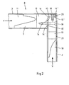
- FIG. 2 is the left upper corner portion of the rear wall frame 8 of the in the Fig. 1 shown case 1 shown.
- the side wall panel 2 and the roof panel 3 which are connected to each other in this corner, the sake of clarity, only the sake of clarity corresponding rear wall frame profiles 10,11 and the connecting element 7 shown. That in the Fig. 2 shown detail of the rear wall frame 8 is shown from a viewing direction from the interior of the box body 1.
- the side wall panel 2 and the roof panel 3 are connected to each other via a connecting element in the form of a rectangular corner reinforcement 5, wherein the connecting element 7 is positively inserted in the two rear wall frame profiles 10,11.
- the connecting element 7 is composed of two different connecting halves 12, 13, wherein the first connecting half 12 is assigned to the roof panel 3 and the second connecting half 13 to the side wall panel 2.
- a dovetail structure is provided at the free end of the first connecting half 12.
- the free end of the second connecting half 13 tapers gradually from the outside in the direction of the inside of the rear wall frame profile 10. Deviating configurations of the free ends of the connecting element formed as an angle are readily conceivable.
- the two connecting halves 12,13 of the connecting element 7 abut against each other at corresponding stop surfaces 14,15.
- the stop surfaces 14,15 are designed such that the two connecting halves 12,13 by the stop surfaces 14,15 both in a first joining direction x vertically in the plane of the side wall panel 2 and in a second joining direction y horizontally in the plane of the roof panel. 3 are positioned against each other.
- the first connection half 12, which is the Roof panel 3 is assigned, on the one hand on the second, the side wall panel 2 associated connection half 13 and at the same time at this.
- the stop surfaces 14,15 of the connecting halves 12,13 of the connecting element 7 extend in the plane defined by the two joining directions x, y plane, which is aligned parallel to the plane of the rear wall frame 8, arcuate.
- This arcuate configuration of the abutment surfaces 14, 15 comprises, for the first connecting half 12 and for the second connecting half 13, in each case a first section 14 ', 15', which is oriented perpendicular to the second joining direction y, and respectively a second section 14 ", 15", which is aligned perpendicular to the first joining direction x.
- the orientation of the portions 14 ', 14 ", 15', 15" of the stop surfaces 14,15 is based on a plane spanned by the two joining directions x, y plane.
- the sections 14 ', 14 ", 15', 15" of the stop surfaces 14,15 as well as the joining directions x, y are aligned perpendicular to each other, the first joining direction x vertically in a plane of the side wall panel 2 and the second joining direction y extends horizontally in a plane of the roof panel 3.
- the two connecting halves 12,13 of the connecting element 7 and thus ultimately the side wall panel 2 and the roof panel 3 are connected to each other via two screws 18,19, the are arranged parallel to a plane defined by the joining directions x, y level.
- the first screw 18 extends parallel to the first joining direction x and the second screw 19 extends parallel to the second joining direction y.
- the second screw 19 in the region of the first portions 14 ', 15' of the stop surfaces 14,15 provided while the first screw 18 in the region of the second portions 14 '', 15 '' of the stop surfaces 14,15 is provided.
- the two connecting halves 12,13 of the connecting element 7 are positively connected to each other in a direction perpendicular to the two joining directions x, y.
- the side wall panel 2 associated connecting half 13 has a groove profile 22 which extends along the entire connection area between the two connecting halves 12,13 extends.
- the groove profile 22 extends centrally and parallel to the abutment surface 15 of the side wall panel 2 associated connecting half 13.
- This abutment surface 15 is divided in a plane parallel to the plane defined by the two joining directions x, y level in two partial stop surfaces 24,25, which located on opposite sides of the groove profile 22. It is not shown in detail that a sealing compound or a sealing element can be provided on the partial stop surfaces 24, 25 of the groove profile 22. Against this sealant or this sealing element of a suitable sealing material, the corresponding connecting half 12 comes in the connected state to the plant.
- the roof panel 3 associated connecting half 12 has a spring profile 26.
- This spring profile 26 also extends along the entire connecting region between the two connecting halves 12,13 and thus also divides the stop surface 14 of the roof panel 3 associated connecting half 12 in two part stop surfaces 27, which are located on opposite sides of the spring profile 26. It is not shown in detail that a sealing compound or a sealing element can be provided on the partial abutment surfaces 27 of the spring profile 26. Against this sealant or this sealing element of a suitable sealing material, the corresponding connecting half 13 comes in the connected state to the plant.
- flanks 28,29 of the spring profile 26 and the groove profile 22 are bevelled with respect to the plane defined by the two joining directions x, y plane. Because of these bevelled edges 28,29 allow the two connecting halves 12,13 a self-centering connection, since the flanks 28,29 of the tongue / groove profiles slide so long until the two connecting halves 12,13 in a direction z perpendicular to the centered on the plane spanned by the two joining directions x, y.
- the screws 18,19 pass through the areas of the connecting halves 12,13, in which the portions of the abutment surfaces 14 ', 14' ', 15', 15 'aligned perpendicular to one of the two joining directions x, y are.
- the two screws 18,19 extend to connect the two connecting halves 12,13 of the connecting element 7 in the plane of the tongue and groove profiles 22,26 of the connecting halves 12,13.
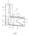
- a right lower corner region of the rear wall frame 8 is shown in a detail.
- This representation is also schematic and takes into account, from the side wall panel 2 and the floor panel 4, which are interconnected in the detail shown, only the back wall frame profiles 30, 31 together with the corner reinforcement. Accordingly, the corner joint seen from the interior of the box body 1 is shown.
- the roof panel 2 associated with the connecting half 12 correspond Fig. 2 and the floor panel 4 associated connection half 12 'from Fig. 5
- the side wall panel 2 associated connection half 13 Fig. 2 and the side wall panel 2 associated connection half 13 'from Fig. 5 Again, the two joining directions x ', y' are again in planes of the two interconnected panels 2,4.
- the two joining directions x ', y' are again in planes of the two interconnected panels 2,4.
- no screw is shown.
- FIG. 12 is a perspective view of the side back frame frame 30 together with the associated connection half 13 ' Fig. 7 is shown, the two corresponding connecting halves 12 ', 13' of the connecting element 7 'for connecting the side wall panel 2 and the bottom panel 4 have corresponding groove / tongue profiles 22', 26 '. Also this profile geometry is in the in the Fig. 5 Corner amplifier shown substantially identical to the tongue and groove profiles 22,26 of the Fig. 2 illustrated corner amplifier.
- each corner amplifier of the type described above in each corner of the end wall frame 9 of the box body 1 is provided.
- the design of the corner amplifier in the end wall frame 9 substantially corresponds to the configuration of the corner amplifier described above.
- the use of the illustrated corner booster in all four corners of both the rear wall frame 8 and the end wall frame 9 allows a particularly simple assembly of the individual panels of the box body 1.
- the side wall panels 2 in a substantially horizontal or at least predominantly horizontal orientation the substantially horizontal floor panel 4 is brought in from the side until the edges of the panels touch, as required, the corner-reinforcing halves of the panels. Subsequently, the side wall panels 2 erected.
- the side wall panels 2 have taken their vertical position, the abutment surfaces of the EckverEntr halves of the two lower corner amplifier abut each other and the Eckverhyroidr halves are screwed together.
Description
Die Erfindung betrifft einen Kofferaufbau eines Lastkraftwagens, Aufliegers und/oder Anhängers, mit einem Seitenwandpaneel sowie einem Dachpaneel und/oder einem Bodenpaneel, wobei das Seitenwandpaneel über ein Verbindungselement mit einem Dachpaneel und/oder einem Bodenpaneel verbunden ist und wobei das Verbindungselement eine dem Seitenwandpaneel zugeordnete Verbindungshälfte und eine dem Dachpaneel und/oder dem Bodenpaneel zugeordnete Verbindungshälfte aufweist.The invention relates to a box body of a truck, trailer and / or trailer, with a Seitenwandpaneel and a Dachpaneel and / or a Bodenpaneel, wherein the Seitenwandpaneel is connected via a connecting element with a Dachpaneel and / or a Bodenpaneel and wherein the connecting element associated with the Seitenwandpaneel Connecting half and a the roof panel and / or the floor panel associated connecting half.
Bei den bekannten Kofferaufbauten der vorgenannten Art handelt es sich im Wesentlichen um Kofferaufbauten mit einen Eckverstärker aufweisenden Rückwandrahmen, wobei die Eckverstärker jeweils aus zwei Eckverstärkerhälften zusammengesetzt sind. Durch die Teilung der Eckverstärker in zwei Eckverstärkerhälften wird die Montage des Rückwandrahmens erleichtert. Entsprechend der jeweiligen Teilung der Eckverstärker wird eine Fügerichtung definiert, in der die beiden Eckverstärkerhälften zusammengefügt werden, bis sie an entsprechenden Anschlagflächen aneinanderliegen. In dieser Position erfolgt dann eine Verschraubung der beiden Eckverstärkerhälften.In the known box bodies of the aforementioned type are essentially to box bodies with a corner amplifier having rear wall frame, the corner amplifiers are each composed of two Eckverstärker halves. By dividing the corner amplifier in two Eckverstärkerhälften the installation of the rear wall frame is facilitated. According to the respective division of the corner amplifier, a joining direction is defined, in which the two Eckverstärkerhälften are joined together until they abut against corresponding abutment surfaces. In this position, then a screw connection of the two Eckverstärker halves.
Ein Kofferaufbau der eingangs genannten Art ist beispielsweise aus der
Die Seitenwandpaneele, das Dachpaneel und das Bodenpaneel des bekannten Kofferaufbaus können bereits entsprechende Teile des Rückwandrahmens mit umfassen. Beim Zusammensetzen der einzelnen Paneele zum Kofferaufbau wird gleichzeitig der Rückwandrahmen aus den einzelnen den unterschiedlichen Paneelen zugeordneten Rückwandrahmenteilen gebildet, so dass zusätzliche Montageschritte eingespart werden können.The side wall panels, the roof panel and the floor panel of the known box body may already include corresponding parts of the rear wall frame with. When assembling the individual panels to the box body, the rear wall frame is simultaneously formed from the individual panels assigned to the different rear wall frame parts, so that additional assembly steps can be saved.
Ein weiterer ähnlicher Kofferaufbau ist in
Die Montage der bekannten Kofferaufbauten ist trotz der Teilung des Verbindungselements in zwei Verbindungshälften mit einem erheblichen Arbeitsaufwand verbunden, der sich unter anderem aus den großen Abmessungen der Paneele des Kofferaufbaus und den geringen Toleranzen, die beim Zusammenbau des Kofferaufbaus eingehalten werden müssen, ergibt. Es besteht daher weiter ein Interesse an einer einfacheren, schnelleren und kostengünstigeren Montage des Kofferaufbaus.The assembly of the known box bodies, despite the division of the connecting element in two connecting halves associated with a considerable amount of work, resulting inter alia from the large dimensions of the panels of the box body and the small tolerances that must be met during assembly of the box body. Therefore, there is still an interest in a simpler, faster and more cost-effective installation of the box body.
Daher liegt der vorliegenden Erfindung die Aufgabe zu Grunde, einen Kofferaufbau derart auszugestalten und weiterzubilden, dass er einfacher, schneller und kostengünstiger zusammengebaut werden kann.Therefore, the present invention is based on the object to design a case structure such and further, that it can be assembled easier, faster and cheaper.
Diese Aufgabe ist bei einem Kofferaufbau gemäß des Oberbegriffs des Anspruchs 1 dadurch gelöst, dass die Verbindungshälften einen Formschluss in einer horizontalen Richtung parallel zur Längserstreckung des Kofferaufbaus bilden.This object is achieved in a case construction according to the preamble of claim 1, characterized in that the connecting halves a positive connection in a horizontal Form direction parallel to the longitudinal extent of the box body.
Die Erfindung hat erkannt, dass der Zusammenbau des Kofferaufbaus erheblich erleichtert werden kann, wenn die beiden Verbindungshälften formschlüssig ineinander greifen, so dass beim Fügen gleichzeitig eine exakte Positionierung der Verbindungshälften jedenfalls in Längserstreckung des Kofferaufbaus zueinander möglich ist. Zudem wird diese Position aufgrund des Formschlusses aber auch bei nachfolgenden Montageschritten beibehalten, bis schließlich die beiden über das Verbindungselement verbundenen Paneele fest und dauerhaft miteinander verbunden sind, wonach ein unbeabsichtigtes Verschieben der Verbindungshälften gegeneinander auch in anderen Raumrichtungen unterbunden wird.The invention has recognized that the assembly of the box body can be considerably facilitated if the two connecting halves engage in a form-fitting manner, so that at the same time an exact positioning of the connecting halves is at least possible in the longitudinal extension of the box body to each other when joining. In addition, this position is maintained due to the positive connection but also in subsequent assembly steps, until finally the two connected via the connecting element panels are firmly and permanently connected to each other, after which unintentional displacement of the connecting halves against each other is also prevented in other spatial directions.
Es hat sich überraschend gezeigt, dass sich die Verwendung von einen Formschluss in Längserstreckung des Kofferaufbaus bildenden Verbindungshälften positiv auf den Montageaufwand auswirkt, denn das formschlüssige Fügen der Verbindungshälften ist zunächst mit einem erhöhten Aufwand verbunden, da das Fügen gleich sehr exakt durchgeführt werden muss. Es ist ein nachträgliches Verschieben der Verbindungshälften gegeneinander nicht mehr oder nur sehr eingeschränkt möglich. Dies führt allerdings wiederum dazu, dass nachfolgende Montageschritte, wie beispielsweise das Verschrauben der Verbindungshälften miteinander, einfacher erfolgen können, da ein Verschieben der Verbindungshälften in Längserstreckung des Kofferaufbaus jedenfalls zum Großteil verhindert wird. Letztlich wird das exakte Positionieren und das Aneinanderlegen der Verbindungshälften in einem Arbeitsschritt zusammengefasst, was also zur Einsparung eines Arbeitsschritts führt, auch wenn der genannte Arbeitsschritt etwas aufwändiger gestaltet ist.It has surprisingly been found that the use of a form fit in the longitudinal extension of the box body forming connecting halves has a positive effect on the assembly effort, because the positive joining of the connecting halves is initially associated with increased effort, since the same must be performed very precisely. It is a subsequent displacement of the connecting halves against each other no longer or only very limited possible. However, this in turn means that subsequent assembly steps, such as screwing the connecting halves together, can be made easier, since a displacement of the connecting halves in the longitudinal extension of the box body is at least largely prevented. Ultimately, the exact positioning and juxtaposition of the connecting halves in one step summarized, which therefore leads to the saving of a work step, even if the mentioned step is designed a little more complex.
Ein weiterer erfindungsgemäßer Vorteil besteht darin, dass durch die entsprechende Ausgestaltung der Verbindungselemente beim fertig montierten Kofferaufbau Kräfte parallel zur Längserstreckung des Kofferaufbaus jedenfalls teilweise von der formschlüssigen Verbindung zwischen den einzelnen Verbindungshälften des Verbindungselements bzw. der verwendeten Verbindungselemente aufgenommen werden können.A further advantage according to the invention is that forces can be absorbed in parallel to the longitudinal extension of the box body in any case in part by the form-fitting connection between the individual connecting halves of the connecting element or the connecting elements used by the corresponding design of the connecting elements in the assembled case.
Bei einer ersten Ausgestaltung des Kofferaufbaus kann eine weitere Vereinfachung der Montage durch Verbindungshälften, die zu einer Selbstzentrierung der Verbindungshälften parallel zur Längserstreckung des Kofferaufbaus führen, erreicht werden. Dadurch wird die exakte Positionierung und damit die Etablierung des Formschlusses deutlich erleichtert. Das Fügen der Verbindungshälften kann letztlich schneller erfolgen.In a first embodiment of the case construction, a further simplification of the assembly by connecting halves, which lead to a self-centering of the connecting halves parallel to the longitudinal extension of the box body can be achieved. As a result, the exact positioning and thus the establishment of the positive connection is much easier. The joining of the connecting halves can ultimately be faster.
Bei einer konstruktiv besonders einfachen Ausführungsform der Verbindungshälften weisen die Verbindungshälften korrespondierende Nut-/Feder-Profile auf. Dies ist eine einfache und kostengünstige Weise einen Formschluss herzustellen, wobei der Formschluss in Richtung der Längsersteckung des Kofferaufbaus sowohl nach vorne als auch nach hinten wirkt.In a structurally particularly simple embodiment of the connecting halves, the connecting halves have corresponding tongue and groove profiles. This is a simple and inexpensive way to produce a positive connection, wherein the positive connection acts in the direction of the longitudinal extent of the box body both forward and backward.
Der Formschluss, beispielsweise durch Ineinanderstecken der Nut-/Feder-Profile, kann dabei prinzipiell in unterschiedlichen Fügerichtungen etabliert werden. Die Fügerichtung ist dabei vorzugsweise horizontal oder vertikal ausgerichtet und senkrecht zur Längserstreckung angeordnet. Alternativ kann die Fügerichtung aber auch eine resultierende Fügerichtung aus einer Überlagerung einer solchen horizontalen und vertikalen Fügerichtung sein. Bei einer besonders bevorzugten Ausgestaltung des Kofferaufbaus kann der Formschluss der Verbindungshälften wahlweise in der horizontalen Fügerichtung, der vertikalen Fügerichtung oder der resultierenden Fügerichtung hergestellt werden. Dadurch wird eine hohe Flexibilität des Verbindens erreicht und es muss nicht eine Fügerichtung ganz exakt eingehalten werden, jedenfalls nicht senkrecht zur Längserstreckung des Kofferaufbaus. Dann passen die Verbindungshälften in jedem Falle aneinander. Dabei können die Verbindungshälften je nach der jeweiligen Fügerichtung an unterschiedlichen Abschnitten des Verbindungsbereichs des Verbindungselements zuerst in Eingriff miteinander kommen. Im Falle von Nut-/Feder-Profilen erfolgt dann vorzugsweise gleichzeitig eine Selbstzentrierung.The positive connection, for example by nesting the tongue / groove profiles, can be established in principle in different joining directions. The joining direction is preferably horizontal or vertical aligned and arranged perpendicular to the longitudinal extent. Alternatively, however, the joining direction can also be a resulting joining direction from a superimposition of such a horizontal and vertical joining direction. In a particularly preferred embodiment of the box body of the positive connection of the connecting halves can be made either in the horizontal joining direction, the vertical joining direction or the resulting joining direction. As a result, a high flexibility of the connection is achieved and it must not be adhered to exactly one joining direction, at least not perpendicular to the longitudinal extent of the box body. Then the connecting halves fit each other in each case. In this case, depending on the respective joining direction, the connecting halves can first come into engagement with one another at different sections of the connecting region of the connecting element. In the case of tongue and groove profiles then preferably takes place simultaneously a self-centering.
In diesem Zusammenhang bietet es sich alternativ oder zusätzlich an, wenn die Verbindungshälften entweder in der ersten vertikalen Fügerichtung und in der zweiten horizontalen Fügerichtung und/oder in der aus der Überlagerung der ersten Fügerichtung sowie der zweiten Fügerichtung resultierenden Fügerichtung fügbar ausgebildet sind, wobei die Verbindungshälften dann wenigstens zwei korrespondierende Anschlagflächen zur Positionierung der Verbindungshälften relativ zueinander in der ersten Fügerichtung und der zweiten Fügerichtung aufweisen.In this context, it is alternatively or additionally suitable if the connecting halves are designed to be available either in the first vertical joining direction and in the second horizontal joining direction and / or in the joining direction resulting from the superposition of the first joining direction and the second joining direction, wherein the connecting halves then have at least two corresponding abutment surfaces for positioning the connecting halves relative to each other in the first joining direction and the second joining direction.
Verbindungshälften mit zwei korrespondierenden, in unterschiedlichen Ebenen liegenden Anschlagflächen erleichtern die Montage des Kofferaufbaus weiter, obwohl die korrespondierenden Konturen der beiden Verbindungshälften im Bereich der Anschlagflächen entsprechend komplizierter ausgestaltet werden müssen, um die beiden in unterschiedlichen Ebenen liegenden Anschlagflächen bereitzustellen. Letztlich muss beim Zusammenbau des erfindungsgemäßen Kofferaufbaus kein besonderer Aufwand dahingehend getrieben werden, dass die Fügerichtungen genau eingehalten werden, um ein exaktes Aneinanderpassen der beiden Verbindungshälften in einer Richtung senkrecht zur Längsertreckung der Kofferaufbaus sicherzustellen, ohne dass eine nachträgliche Justierung der Verbindungshälften gegeneinander erforderlich wäre. Dies führt letztlich nicht nur zu einem Zeitgewinn beim Zusammenbau des erfindungsgemäßen Kofferaufbaus, sondern auch zu einer Vereinfachung der für das positionsgenaue zusammenfügen der Verbindungshälften erforderlichen Vorrichtungen.Connecting halves with two corresponding, lying in different planes stop surfaces facilitate the assembly of the box body on, although the Corresponding contours of the two connecting halves in the region of the stop surfaces must be configured correspondingly more complicated in order to provide the two lying in different planes stop surfaces. Ultimately, when assembling the box body according to the invention no special effort must be driven to ensure that the joining directions are precisely maintained to ensure a precise matching of the two connecting halves in a direction perpendicular to the Längsertreckung the box body without a subsequent adjustment of the connecting halves against each other would be required. This ultimately leads not only to a gain in time when assembling the box body according to the invention, but also to simplify the necessary for the positionally accurate joining of the connecting halves devices.
Sofern es zu Abweichungen in der vorgesehenen Fügerichtung senkrecht zur Längserstreckung des Kofferaufbaus kommt, können die beiden Verbindungshälften trotzdem positionsgenau gefügt werden, da die beiden Anschlagflächen der Verbindungshälften auch dann nach dem Fügen exakt aneinander anliegen. Ein weiterer Vorteil dieser Ausgestaltung liegt darin, dass die Fügerichtungen an die Gegebenheiten des Einzelfalls angepasst werden können, ohne dass andere Verbindungselemente verwendet oder nachfolgende Justierungsschritte vorgesehen werden müssen. Dies bedeutet letztlich auch, dass bei Verwendung von einheitlichen Verbindungselementen, beispielsweise in allen Ecken des Kofferaufbaus, einzelne Paneele des Kofferaufbaus in einer ersten Fügerichtung und andere Paneele des Kofferaufbaus in einer zweiten Fügerichtung verbunden werden können, ohne dass es hierbei zu Fertigungsproblemen kommt. Selbst drei oder mehr unterschiedliche Fügerichtungen sind bei einem Kofferaufbau mit einheitlichen Verbindungselementen möglich, wenn hieran Bedarf besteht.If there are deviations in the intended joining direction perpendicular to the longitudinal extension of the box body, the two connecting halves can still be joined positionally accurate, since the two abutment surfaces of the connecting halves also abut each other exactly after joining. Another advantage of this embodiment is that the joining directions can be adapted to the circumstances of the individual case, without having to use other connecting elements or subsequent adjustment steps must be provided. This ultimately means that when using uniform fasteners, for example in all corners of the box body, individual panels of the box body in a first joining direction and other panels of the box body can be connected in a second joining direction, without this leading to manufacturing problems. Even three or more different joining directions are at one Box body with uniform fasteners possible, if there is a need.
Nicht zuletzt können bei dieser Ausgestaltung die Verbindungshälften ohne weiteres in drei zueinander unabhängigen Raumrichtungen relativ zueinander positioniert werden. Dabei ist eine Raumrichtung vorzugsweise parallel zur Längserstreckung des Kofferaufbaus.Not least, in this embodiment, the connection halves can be positioned relative to each other in three mutually independent spatial directions readily. In this case, a spatial direction is preferably parallel to the longitudinal extension of the box body.
In diesem Zusammenhang weisen die wenigstens zwei Anschlagflächen jeweils einen ersten Abschnitt senkrecht zur zweiten Fügerichtung und einen zweiten Abschnitt senkrecht zur ersten Fügerichtung auf. In diesem Falle legen der erste Abschnitt und der zweite Abschnitt der wenigstens zwei Anschlagflächen die Lage der Verbindungshälften relativ zueinander und unabhängig voneinander in beiden Fügerichtungen fest. Es kommt dabei in keiner der beiden Fügerichtungen zu einem unbeabsichtigten seitlichen Verschieben der Verbindungshälften gegeneinander in einer Richtung parallel zu dem entsprechenden Abschnitt der Anschlagflächen. In diesem Zusammenhang sind der erste Abschnitt und der zweite Abschnitt der wenigstens zwei Anschlagflächen senkrecht zueinander ausgerichtet.In this context, the at least two stop surfaces each have a first portion perpendicular to the second joining direction and a second portion perpendicular to the first joining direction. In this case, the first portion and the second portion of the at least two abutment surfaces define the position of the connecting halves relative to one another and independently of each other in both joining directions. It comes in any of the two joining directions to an unintentional lateral displacement of the connecting halves against each other in a direction parallel to the corresponding portion of the abutment surfaces. In this context, the first portion and the second portion of the at least two stop surfaces are aligned perpendicular to each other.
Alternativ oder zusätzlich kann die Fixierung der Verbindungshälften durch zwei in einer durch die erste Fügerichtung und die zweite Fügerichtung aufgespannten Ebene angeordnete Schrauben verbunden sein. Wenn beide Schrauben in einer nicht parallelen Ausrichtung zueinander vorgesehen sind, kann jede der beiden Schrauben durch Aufnahme von Zugkräften die jeweils andere Schraube in Bezug auf die Scherkräfte entlasten. Gleichzeitig erfährt der Kofferaufbau eine Stabilisierung gegenüber im Betrieb des Kofferaufbaus auftretenden Verschränkungskräften.Alternatively or additionally, the fixing of the connecting halves can be connected by two screws arranged in a plane defined by the first joining direction and the second joining direction. If both screws are provided in a non-parallel alignment with each other, each of the two screws can absorb the other screw by absorbing tensile forces with respect to the shear forces. At the same time the box body undergoes a Stabilization against entanglement forces occurring during operation of the box body.
In diesem Zusammenhang ist es besonders bevorzugt, wenn eine erste Schraube sich parallel zur ersten Fügerichtung und eine zweite Schraube sich parallel zur zweiten Fügerichtung erstreckt. Jede dieser Schrauben kann dann in der entsprechenden Fügerichtung Zugkräfte aufnehmen und das Auftreten von übermäßigen Scherkräften an der jeweils anderen Schraube verhindern. Bei einer weiter bevorzugten Ausgestaltung sind die Fügerichtungen und damit die Schrauben senkrecht zueinander angeordnet. In der durch die Fügerichtungen aufgespannten Ebene wirkt dann jeweils eine von zwei normal zueinanderstehenden Komponenten der durch die Verschränkung des Kofferaufbaus hervorgerufenen Kräfte als Zugkraft auf eine der beiden Schrauben. In diesem Zusammenhang sind die Fügerichtungen vorzugsweise beide senkrecht zur Längserstreckung des Kofferaufbaus angeordnet, da in dieser Ebene durch die Verschränkung des Kofferaufbaus besonders hohe Kräfte auf das Verbindungselement wirken.In this context, it is particularly preferred if a first screw extends parallel to the first joining direction and a second screw extends parallel to the second joining direction. Each of these screws can then absorb tensile forces in the corresponding joining direction and prevent the occurrence of excessive shear forces on the other screw. In a further preferred embodiment, the joining directions and thus the screws are arranged perpendicular to each other. In the plane defined by the joining directions, one of two normal components of the forces caused by the entanglement of the box body then acts as a pulling force on one of the two screws. In this context, the joining directions are preferably both arranged perpendicular to the longitudinal extension of the box body, as act in this plane by the entanglement of the box body particularly high forces on the connecting element.
Damit die Anschlagflächen der beiden Verbindungshälften dauerhaft aneinander anliegen und auch im Falle einer extremen Verschränkung des Kofferaufbaus nicht voneinander beabstandet werden, bietet es sich an, die ersten Abschnitte der Anschlagflächen durch die zweite Schraube und die zweiten Abschnitte der Anschlagflächen durch die erste Schraube kraftschlüssig miteinander zu verbinden. In diesem Zusammenhang sind die Schrauben vorzugsweise senkrecht zu den jeweiligen Anschlagflächen ausgerichtet. Ungünstige Kippmomente in Bezug auf die beiden Verbindungshälften können dadurch minimiert werden, dass die beiden Schrauben die Abschnitte der Anschlagflächen im Wesentlichen durchdringen oder jedenfalls in einer Richtung mittig zu dem jeweiligen Abschnitt angeordnet sind. Dies erlaubt zudem eine platzsparende Ausgestaltung der Verbindungselemente.Thus, the abutment surfaces of the two connecting halves permanently abut each other and are not spaced apart in the case of extreme entanglement of the box body, it is advisable, the first portions of the abutment surfaces by the second screw and the second portions of the abutment surfaces by the first screw positively to each other connect. In this context, the screws are preferably aligned perpendicular to the respective stop surfaces. Unfavorable tilting moments in relation to the two connecting halves can be minimized by the fact that the two screws Sections of the abutment surfaces substantially penetrate or at least are arranged in a direction centered to the respective section. This also allows a space-saving design of the connecting elements.
Bei einer weiter bevorzugten Ausgestaltung des Kofferaufbaus sind die Anschlagflächen in Bezug auf die durch die erste Fügerichtung und die zweite Fügerichtung aufgespannte Ebene gebogen ausgebildet. Eckbereiche, in denen Spannungsspitzen auftreten können, werden auf diese Weise vermieden. Darüber hinaus steht in diesem Falle jede erdenkliche Fügerichtung, die innerhalb von der ersten und der zweiten Fügerichtung aufgespannten Ebene liegt, im Wesentlichen senkrecht auf einem bestimmten Abschnitt der korrespondierenden Anschlagflächen. So können in jeder dieser Richtungen Normalkräfte übertragen werden.In a further preferred embodiment of the box body, the stop surfaces are formed bent relative to the plane defined by the first joining direction and the second joining direction. Corner areas in which voltage peaks can occur are avoided in this way. Moreover, in this case, any imaginable joining direction, which lies within the plane defined by the first and the second joining direction, is substantially perpendicular to a specific section of the corresponding stop surfaces. Thus, normal forces can be transmitted in each of these directions.
Um möglichst langgestreckte Anschlagflächen zu erhalten, kann die eine Verbindungshälfte sich bis zur Rückseite der anderen Verbindungshälfte erstrecken. Dann liegt eine der beiden Verbindungshälften auf der jeweils anderen Verbindungshälfte über die gesamte in der durch die Fügerichtungen aufgespannten Ebene liegenden Breite auf.In order to obtain as long as possible stop surfaces, the one half of the connection can extend to the back of the other half of the connection. Then one of the two connecting halves rests on the other half of the connection over the entire width lying in the plane defined by the joining directions.
Zum Abdichten der Verbindung zwischen dem Seitenwandpaneel einerseits und dem Dachpaneel und/oder dem Bodenpaneel andererseits, kann zwischen den Anschlagflächen eine Dichtmasse und/oder ein Dichtelement vorgesehen sein. Es versteht sich in diesem Zusammenhang, dass die Anschlagflächen im Sinne der Erfindung auch dann als solche angesehen werden, wenn diese durch ein dazwischen befindliches Dichtelement bzw. eine dazwischen befindliche Dichtmasse voneinander beabstandet sind.For sealing the connection between the side wall panel on the one hand and the roof panel and / or the floor panel on the other hand, a sealing compound and / or a sealing element can be provided between the stop surfaces. It is understood in this context that the abutment surfaces are considered as such within the meaning of the invention even if they are by a sealing element located therebetween or an interposed sealant are spaced from each other.
Im Falle der Verwendung einer Dichtmasse und/oder eines Dichtelements, kann es zweckmäßig sein, wenn wenigstens eine Verbindungshälfte eine Hinterschneidung zur Aufnahme von überschüssiger Dichtmasse und/oder des überschüssigen Teils des Dichtelements aufweist. Bei Verwendung eines Dichtelements kann dieses auch derart in der Hinterschneidung aufgenommen sein, dass das Dichtelement dort unabhängig von einer Verbindung der beiden Verbindungshälften in der gewünschten Position gehalten wird.In the case of using a sealant and / or a sealing element, it may be expedient if at least one connecting half has an undercut for receiving excess sealant and / or the excess part of the sealing element. If a sealing element is used, it can also be received in the undercut in such a way that the sealing element is held there in the desired position independently of a connection of the two connecting halves.
Das aus zwei verbindungshälften zusammengesetzte Verbindungselement kann grundsätzlich an jeder Stelle zwischen einem Seitenwandpaneel sowie einem Dachpaneel und/oder einem Bodenpaneel vorgesehen sein. Bedarfsweise ist es auch möglich, dass sich das Verbindungselement entlang des gesamten Seitenwandpaneels erstreckt. Unter anderem aus Gewichtsgründen wird das Verbindungselement allerdings vorzugsweise nur an bestimmten Stellen der Verbindung zwischen dem Seitenwandpaneel und dem Dachpaneel und/oder dem Bodenpaneel vorgesehen sein. Insbesondere liegen diese Stellen in den Eckbereichen des Kofferaufbaus. Folglich handelt es sich bei dem Verbindungselement also vorzugsweise um einen sogenannten Eckverstärker. Der Eckverstärker kann dabei im Wesentlichen winkelförmig ausgebildet sein, wobei jede Verbindungshälfte einen Schenkel des Verbindungselements bzw. des Winkels repräsentieren kann. Zudem kann die Längserstreckung eines jeden dieser Schenkel parallel zu einer der beiden Fügerichtungen sein.The connecting element composed of two connection halves can basically be provided at any point between a side wall panel and a roof panel and / or a floor panel. If necessary, it is also possible that the connecting element extends along the entire side wall panel. However, for reasons of weight, the connecting element is preferably provided only at certain points of the connection between the side wall panel and the roof panel and / or the floor panel. In particular, these places are in the corners of the box body. Consequently, the connecting element is thus preferably a so-called corner amplifier. The corner amplifier may be formed substantially angularly, each connecting half may represent a leg of the connecting element or the angle. In addition, the longitudinal extension of each of these legs may be parallel to one of the two joining directions.
Nachfolgend ist die Verbindung anhand lediglich ein Ausführungsbeispiel darstellenden Zeichnung näher erläutert.
Darin zeigt
- Fig. 1
- einen Lastkraftwagen mit einem einen erfindungsgemäßen Kofferaufbau aufweisenden Auflieger,
- Fig. 2
- ein Detail des oberen Rückwandrahmens des Kofferaufbaus gemäß II aus
Fig. 1 in schematischer, freigeschnittener Ansicht, - Fig. 3
- das Detail aus
Fig. 2 in einer Explosionsdarstellung, - Fig. 4
- den oberen Teil des Rückwandrahmens aus
Fig. 3 in einer perspektivischen Ansicht, - Fig. 5
- ein Detail des unteren Rückwandrahmens des Kofferaufbaus gemäß V aus
Fig. 1 in einer schematischen, freigeschnittenen Ansicht, - Fig. 6
- das Detail aus
Fig. 5 in einer Explosionsdarstellung und - Fig. 7
- den linken Teil des Details aus
Fig. 6 in einer perspektivischen Ansicht.
It shows
- Fig. 1
- a truck with a semitrailer having a box body according to the invention,
- Fig. 2
- a detail of the upper rear wall frame of the box body according to II
Fig. 1 in a schematic, cutaway view, - Fig. 3
- the detail
Fig. 2 in an exploded view, - Fig. 4
- the upper part of the rear wall frame
Fig. 3 in a perspective view, - Fig. 5
- a detail of the lower rear wall frame of the box body according to V from
Fig. 1 in a schematic, cut-away view, - Fig. 6
- the detail
Fig. 5 in an exploded view and - Fig. 7
- the left part of the detail
Fig. 6 in a perspective view.
In der
Der Kofferaufbau könnte alternativ auch direkt auf einem Lastkraftwagen oder einem nicht auf dem Lastkraftwagen aufliegenden Anhänger montiert sein. Dann würden sich prinzipiell die gleichen Effekte und Vorteile ergeben. Zudem müssen die Seitenwandpaneele, das Dachpaneel und das Bodenpaneel nicht als mehrschichtige oder mehrlagige Paneele ausgebildet sein, obwohl das Einbringen eines geschäumten Kunststoffmaterials zwischen zwei Decklagen zur Isolation und Stabilisierung bei gleichzeitig geringem Gewicht bevorzugt ist. Das Dachpaneel, das Bodenpaneel und/oder die Seitenwandpaneele könnten auch eine andere Struktur aufweisen, z.B. massiv ausgebildet sein.Alternatively, the box body could be mounted directly on a truck or a trailer not resting on the truck. In that case, the same effects and advantages would arise in principle. In addition, the side wall panels, the roof panel and the floor panel need not be formed as multi-layer or multi-layer panels, although the introduction of a foamed plastic material between two cover layers for insulation and stabilization with low weight is preferred. The roof panel, the floor panel and / or the sidewall panels could also have a different structure, e.g. be formed solid.
In der
Das Verbindungselement 7 ist aus zwei unterschiedlichen Verbindungshälften 12,13 zusammengesetzt, wobei die erste Verbindungshälfte 12 dem Dachpaneel 3 und die zweite Verbindungshälfte 13 dem Seitenwandpaneel 2 zugeordnet ist. Bei dem dargestellten und insoweit bevorzugten Ausführungsbeispiel ist am freien Ende der ersten Verbindungshälfte 12 eine Schwalbenschwanzstruktur vorgesehen. Dagegen verjüngt sich das freie Ende der zweiten Verbindungshälfte 13 allmählich von der Außenseite in Richtung zur Innenseite des Rückwandrahmenprofils 10. Davon abweichende Ausgestaltungen der freien Enden des als Winkel ausgebildeten Verbindungselements sind ohne weiteres denkbar.The connecting
Die beiden Verbindungshälften 12,13 des Verbindungselements 7 liegen an korrespondierenden Anschlagflächen 14,15 aneinander an. Die Anschlagflächen 14,15 sind dabei derart ausgestaltet, dass die beiden Verbindungshälften 12,13 durch die Anschlagflächen 14,15 sowohl in einer ersten Fügerichtung x vertikal in der Ebene des Seitenwandpaneels 2 als auch in einer zweiten Fügerichtung y horizontal in der Ebene des Dachpaneels 3 gegeneinander positioniert sind. Mit anderen Worten liegt die erste Verbindungshälfte 12, die dem Dachpaneel 3 zugeordnet ist, einerseits auf der zweiten, dem Seitenwandpaneel 2 zugeordneten Verbindungshälfte 13 auf und gleichzeitig an dieser an.The two connecting
Die Anschlagflächen 14,15 der Verbindungshälften 12,13 des Verbindungselements 7 verlaufen in der durch die beiden Fügerichtungen x,y aufgespannten Ebene, die parallel zur Ebene des Rückwandrahmens 8 ausgerichtet ist, bogenförmig. Diese bogenförmige Ausgestaltung der Anschlagflächen 14,15 umfasst für die erste Verbindungshälfte 12 und für die zweite Verbindungshälfte 13 jeweils einen ersten Abschnitt 14',15', der senkrecht zur zweiten Fügerichtung y ausgerichtet ist, und jeweils einen zweiten Abschnitt 14", 15", der senkrecht zur ersten Fügerichtung x ausgerichtet ist. Die Ausrichtung der Abschnitte 14',14 ",15',15 " der Anschlagflächen 14,15 ist dabei bezogen auf eine durch die beiden Fügerichtungen x,y aufgespannte Ebene.The stop surfaces 14,15 of the connecting
Im dargestellten und insoweit bevorzugten Ausführungsbeispiel sind die Abschnitte 14',14 ",15',15 " der Anschlagflächen 14,15 ebenso wie die Fügerichtungen x,y senkrecht zueinander ausgerichtet, wobei die erste Fügerichtung x vertikal in einer Ebene des Seitenwandpaneels 2 und die zweite Fügerichtung y horizontal in einer Ebene des Dachpaneels 3 verläuft. Zudem befindet sich jeweils zwischen den beiden Abschnitten 14',14",15',15 " der Anschlagflächen 14,15 eine im Wesentlichen einem Viertelkreis entsprechende Anschlagflächenkontur 16.In the illustrated preferred embodiment, the
Die beiden Verbindungshälften 12,13 des Verbindungselements 7 und damit letztlich das Seitenwandpaneel 2 und das Dachpaneel 3 werden über zwei Schrauben 18,19 miteinander verbunden, die parallel zu einer durch die Fügerichtungen x,y aufgespannten Ebene angeordnet sind. Bei dem dargestellten und insoweit bevorzugten Ausführungsbeispiel erstreckt sich die erste Schraube 18 parallel zur ersten Fügerichtung x und erstreckt sich die zweite Schraube 19 parallel zur zweiten Fügerichtung y. Dabei ist die zweite Schraube 19 im Bereich der ersten Abschnitte 14' ,15' der Anschlagflächen 14,15 vorgesehen, während die erste Schraube 18 im Bereich der zweiten Abschnitte 14'',15'' der Anschlagflächen 14,15 vorgesehen ist. Durch die entsprechenden Schraubenkräfte werden die ersten Abschnitte 14', 15' und die zweiten Abschnitte 14'',15'' der korrespondierenden Anschlagflächen 14,15 kraftschlüssig aneinander gehalten.The two connecting
Durch die gebogene Ausgestaltung der korrespondierenden Anschlagflächen 14,15 der miteinander verbundenen Verbindungshälften 12,13 weist die erste, dem Dachpaneel 3 zugeordnete Verbindungshälfte 12 an ihrer Oberseite einen Vorsprung 20 auf, der bis zur Rückseite 21 der zweiten Verbindungshälfte 13 reicht, wobei die Rückseite 21 der zweiten Verbindungshälfte 13 in Richtung der Außenseite des Seitenwandpaneels 2 weist.Due to the curved configuration of the corresponding stop surfaces 14,15 of the interconnected connection halves 12,13, the first, the
Wie insbesondere in der Explosionsdarstellung des Eckbereichs der
Das Nutprofil 22 verläuft dabei mittig und parallel zu der Anschlagfläche 15 der dem Seitenwandpaneel 2 zugeordneten Verbindungshälfte 13. Diese Anschlagfläche 15 wird dabei in einer Ebene parallel zu der durch die beiden Fügerichtungen x,y aufgespannten Ebene in zwei Teilanschlagflächen 24,25 unterteilt, die sich auf gegenüberliegenden Seiten des Nutprofils 22 befinden. Nicht im Einzelnen dargestellt ist, dass auf den Teilanschlagflächen 24, 25 des Nutprofils 22 eine Dichtmasse oder ein Dichtelement vorgesehen sein kann. Gegen diese Dichtmasse oder dieses Dichtelement aus einem geeigneten Dichtmaterial kommt die korrespondierende Verbindungshälfte 12 im verbundenen Zustand zur Anlage.The
Korrespondierend zu dem Nutprofil 22 der dem Seitenwandpaneel 2 zugeordneten Verbindungshälfte 13, weist die dem Dachpaneel 3 zugeordnete Verbindungshälfte 12 ein Federprofil 26 auf. Dieses Federprofil 26 erstreckt sich ebenfalls entlang des gesamten Verbindungsbereichs zwischen den beiden Verbindungshälften 12,13 und teilt damit ebenfalls die Anschlagfläche 14 der dem Dachpaneel 3 zugeordneten Verbindungshälfte 12 in zwei Teilanschlagsflächen 27, die sich auf gegenüberliegenden Seiten des Federprofils 26 befinden. Nicht im Einzelnen dargestellt ist, dass auf den Teilanschlagflächen 27 des Federprofils 26 eine Dichtmasse oder ein Dichtelement vorgesehen sein kann. Gegen diese Dichtmasse oder dieses Dichtelement aus einem geeigneten Dichtmaterial kommt die korrespondierende Verbindungshälfte 13 im verbundenen Zustand zur Anlage.Corresponding to the
Die Flanken 28,29 des Federprofils 26 und des Nutprofils 22 sind gegenüber der durch die beiden Fügerichtungen x,y aufgespannten Ebene abgeschrägt. Aufgrund dieser abgeschrägten Flanken 28,29 ermöglichen die beiden Verbindungshälften 12,13 eine selbstzentrierende Verbindung, da die Flanken 28,29 der Nut-/Feder-Profile so lange aneinander abgleiten, bis die beiden Verbindungshälften 12,13 in einer Richtung z senkrecht zu der durch die beiden Fügerichtungen x,y aufgespannten Ebene zentriert aneinanderliegen.The
Bei dem dargestellten und insoweit bevorzugten Ausführungsbeispiel verlaufen die Schrauben 18,19 durch die Bereiche der Verbindungshälften 12,13, in denen die Abschnitte der Anschlagflächen 14',14'',15',15' senkrecht zu einer der beiden Fügerichtungen x, y ausgerichtet sind. Zudem verlaufen die beiden Schrauben 18,19 zum Verbinden der beiden Verbindungshälften 12,13 des Verbindungselements 7 in der Ebene der Nut-/Feder-Profile 22,26 der Verbindungshälften 12,13. Dabei beruht ein Vorteil darin, dass in einer Richtung parallel zur Längserstreckung des Kofferaufbaus 1 zu beiden Seiten der vorzugsweise beiden Schrauben 18,19 ein Teil der Anschlagfläche vorgesehen ist. Das erhöht die Stabilität und vermindert die Gefahr eines übermäßigen Kippmoments.In the illustrated preferred embodiment, the
In der
Entsprechende Schraubverbindungen sind jedoch vorhanden, wie in der Explosionsdarstellung der Eckverbindung aus
Wie insbesondere in der
Nicht im Einzelnen dargestellt ist, dass bei dem dargestellten und insoweit bevorzugten Ausführungsbeispiel auch jeweils ein Eckverstärker der zuvor beschriebenen Art in jeder Ecke des Stirnwandrahmens 9 des Kofferaufbaus 1 vorgesehen ist. Die Ausgestaltung der Eckverstärker im Stirnwandrahmen 9 entspricht im Wesentlichen der Ausgestaltung der zuvor beschriebenen Eckverstärker.It is not shown in detail that in the illustrated and so far preferred embodiment, in each case a corner amplifier of the type described above in each corner of the end wall frame 9 of the box body 1 is provided. The design of the corner amplifier in the end wall frame 9 substantially corresponds to the configuration of the corner amplifier described above.
Die Verwendung des dargestellten und insoweit bevorzugten Eckverstärkers in allen vier Ecken sowohl des Rückwandrahmens 8 als auch des Stirnwandrahmens 9 erlaubt einen besonders einfachen Zusammenbau der einzelnen Paneele des Kofferaufbaus 1. Dabei werden zunächst die Seitenwandpaneele 2 in einer im Wesentlichen horizontalen oder jedenfalls überwiegend horizontalen Ausrichtung an das im Wesentlichen horizontale Bodenpaneel 4 von der Seite herangeführt, bis sich die Kanten der Paneele, bedarfsweise die Eckverstärkerhälften der Paneele, berühren. Anschließend werden die Seitenwandpaneele 2 aufgerichtet. Wenn die Seitenwandpaneele 2 ihre senkrechte Position eingenommen haben, liegen die Anschlagflächen der Eckverstärkerhälften der beiden unteren Eckverstärker aneinander an und werden die Eckverstärkerhälften miteinander verschraubt. Nachdem auf diese Weise das Bodenpaneel 4 und die beiden Seitenwandpaneele 2 miteinander verbunden sind, werden die oberen Ränder der Seitenwandpaneele 2 geringfügig nach außen gebogen. Dann wird das Dachpaneel 3 von oben herabgelassen, bis es mit seinen Eckverstärkerhälften auf den oberen Eckverstärkerhälften der Seitenwandpaneele 2 aufliegt. Anschließend werden die oberen Ränder der Seitenwandpaneele 2 in Richtung des Dachpaneels 3 gedrückt oder gezogen, etwa durch das Anziehen der horizontalen, die Eckverstärkerhälften verbindenden Schrauben 18,19.The use of the illustrated corner booster in all four corners of both the
Claims (14)
- Box body (1) of a lorry (L), a semi-trailer (A) and/or trailer, with a side wall panel (2) and a roof panel (3) and/or a floor panel (4), wherein the side wall panel (2) is connected to a roof panel (3) and/or a floor panel (4) via a connecting element (7, 7') and wherein the connecting element (7, 7') has a connection half (13, 13') associated with the side wall panel (2) and a connection half (12, 12') associated with the roof panel (3) and/or the floor panel (4), characterised in that the connection halves (12, 12', 13, 13') form a positive fit in a horizontal direction (z) parallel to the longitudinal extent of the box body (1).
- Box body according to Claim 1, characterised in that the connection halves (12, 12', 13, 13') are self-centring in the direction (z) parallel to the longitudinal extent of the box body (1).
- Box body according to Claim 1 or Claim 2, characterised in that the connection halves (12, 12', 13, 13') have corresponding groove and tongue profiles (22, 22', 26, 26').
- Box body according to Claim 3, characterised in that the groove and tongue profiles (22, 22', 26, 26') are designed to insert into each other in a first vertical joining direction (x, x'), in a second horizontal joining direction (y, y') and/or in a joining direction resulting from an overlap of the first joining direction (x, x') and the second joining direction (y, y'), and in that the first joining direction (x, x') and the second joining direction (y, y') are formed perpendicular to the longitudinal extent of the body.
- Box body according to any one of the Claims 1 to 4, characterised in that the connection halves (12, 12', 13, 13') are designed to be joinable either in the first vertical joining direction (x, x') and the second horizontal joining direction (y, y') and/or in the joining direction resulting from the overlap of the first joining direction (x, x') and the second joining direction (y, y'), and in that the connection halves (12, 12', 13, 13') have at least two corresponding stop faces (14, 15) for positioning the connection halves (12, 12', 13, 13') relative to each other in the first joining direction (x, x') and the second joining direction (y, y').
- Box body according to Claim 5, characterised in that the at least two stop faces (14, 15) respectively have a first section (14',15') perpendicular to the second joining direction (y, y') and a second section (14" ,15") perpendicular to the first joining direction (x, x').
- Box body according to any one of Claims 1 to 6, characterised in that the connection halves (12, 12', 13, 13') are connected by two bolts (18, 19, 19') arranged in a plane spanned by the first joining direction (x, x') and the second joining direction (y, y').
- Box body according to Claim 7, characterised in that a first bolt (18) extends parallel to the first joining direction (x, x') and a second bolt (19, 19') extends parallel to the second joining direction (y, y'),
- Box body according to Claim 7 or Claim 8, characterised in that the first sections (14', 15') of the stop faces (14, 15) are connected to each other in a non-positive manner by the first bolt (18) and the second sections (14", 15") of the stop faces (14, 15) are connected to each other in a non-positive manner by the second bolt (19, 19').
- Box body according to any one of Claims 5 to 9 characterised in that the stop faces (14, 15) run curved in the plane spanned by the first joining direction (x, x') and the second joining direction (y, y').
- Box body according to any one of Claims 1 to 10 characterised in that the one connection half (12, 12') extends to the rear side (21) of the other connection half (13, 13').
- Box body according to any one of Claims 5 to 11 characterised in that a sealing compound and/or a sealing element is provided between the stop faces (14, 15)
- Box body according to Claim 12 characterised in that at least one connection half (12, 12', 13, 13') has an undercut to receive excess sealing compound and/or excess sealing material.
- Box body according to any one of Claims 1 to 13 characterised in that the connecting element (7, 7') is a corner reinforcement, preferably of a rear wall frame (8) and/or of a front wall frame (5).
Priority Applications (1)
| Application Number | Priority Date | Filing Date | Title |
|---|---|---|---|
| EP20080103905 EP2116460B1 (en) | 2008-05-09 | 2008-05-09 | Box body with a connecting element with two connecting halves |
Applications Claiming Priority (1)
| Application Number | Priority Date | Filing Date | Title |
|---|---|---|---|
| EP20080103905 EP2116460B1 (en) | 2008-05-09 | 2008-05-09 | Box body with a connecting element with two connecting halves |
Publications (2)
| Publication Number | Publication Date |
|---|---|
| EP2116460A1 EP2116460A1 (en) | 2009-11-11 |
| EP2116460B1 true EP2116460B1 (en) | 2012-06-27 |
Family
ID=39719078
Family Applications (1)
| Application Number | Title | Priority Date | Filing Date |
|---|---|---|---|
| EP20080103905 Active EP2116460B1 (en) | 2008-05-09 | 2008-05-09 | Box body with a connecting element with two connecting halves |
Country Status (1)
| Country | Link |
|---|---|
| EP (1) | EP2116460B1 (en) |
Families Citing this family (2)
| Publication number | Priority date | Publication date | Assignee | Title |
|---|---|---|---|---|
| DE202010011050U1 (en) * | 2010-08-04 | 2011-11-18 | Brüggen Oberflächen- und Systemlieferant GmbH | Wall structure of a transport vehicle with side walls |
| EP4296148A1 (en) * | 2022-06-24 | 2023-12-27 | Schmitz Cargobull AG | Box body with back panel and commercial vehicles with a box body |
Family Cites Families (5)
| Publication number | Priority date | Publication date | Assignee | Title |
|---|---|---|---|---|
| FI92376C (en) * | 1992-10-09 | 1994-11-10 | Eurocon Oy | Vehicle load compartment structure |
| US5588693A (en) * | 1994-08-31 | 1996-12-31 | Higginson; Roy C. | Modular truck cargo area body |
| GB2336137B (en) * | 1998-03-21 | 2002-05-01 | Brian Jenkins | A frame member and a frame assembly |
| IT1305327B1 (en) | 1998-08-06 | 2001-05-04 | Furgocar Srl | SYSTEM AND METHOD TO CREATE A RECTANGULAR FRAME FOR CASSONENE IN THERMAL INSULATION VANS |
| DE102006030922A1 (en) * | 2006-07-03 | 2008-01-10 | Schmitz Cargobull Ag | Box-type van body for commercial motor vehicle, has roof and side units provided with frame units, which are combined with wall frames, where frame units have edge connecting units that are connected with each other by cutting connection |
-
2008
- 2008-05-09 EP EP20080103905 patent/EP2116460B1/en active Active
Also Published As
| Publication number | Publication date |
|---|---|
| EP2116460A1 (en) | 2009-11-11 |
Similar Documents
| Publication | Publication Date | Title |
|---|---|---|
| DE60013027T2 (en) | Component and method for its production | |
| EP2004453B1 (en) | Crashbox and damping arrangement with a crashbox | |
| EP3105109B1 (en) | Width-adjustable modular heavy goods vehicle, and transverse frame module for a heavy goods vehicle of said type | |
| EP0333772B1 (en) | Modular building system | |
| EP1643049B1 (en) | Construction with structural profiles | |
| EP2870055A1 (en) | Motor vehicle with a vehicle frame | |
| EP1623881B1 (en) | Crashbox for motor vehicles | |
| DE102016124078B3 (en) | Connecting arrangement for the connection of two control cabinet frame racks | |
| DE2701905A1 (en) | KIT OF SEVERAL EXTRUDED PROFILES FOR THE MANUFACTURING OF WALLS, IN PARTICULAR FOR BODIES OF MOTOR VEHICLES | |
| DE60111777T2 (en) | ARRANGEMENT FOR CONNECTING FRAME LENGTH SUPPLEMENTS | |
| DE69734632T2 (en) | Heat-insulating partition body for insertion between aluminum profiles for use in the manufacture of doors and windows | |
| DE2702691C3 (en) | Bumper, in particular for a motor vehicle | |
| EP3546324A1 (en) | Bumper assembly for a motor vehicle | |
| EP2725159A1 (en) | Holding device, method for producing a holding device, and use of a holding device on a curtain wall | |
| EP2116460B1 (en) | Box body with a connecting element with two connecting halves | |
| DE19539862A1 (en) | Hollow profiles corner connection, especially for window and door frames | |
| DE4227532C2 (en) | Frame profile for the frame of a control cabinet | |
| EP0079068B1 (en) | Trailer for motor vehicles | |
| EP2524857B1 (en) | System with individual modules for forming a box body | |
| EP1132562B1 (en) | carriage fitting for a sliding wing | |
| EP0791528A2 (en) | Body structure for a commercial vehicle, in particular a rescue vehicle such as a fire-fighting vehicle | |
| DD270560A5 (en) | TRAEGER FOR WINDOW FRAME | |
| DE102006001045B4 (en) | Corner connector for door or window frame | |
| EP2524858B1 (en) | Individual module for a box body of a commercial vehicle | |
| DE19619617C1 (en) | Modular component for composite structure |
Legal Events
| Date | Code | Title | Description |
|---|---|---|---|
| PUAI | Public reference made under article 153(3) epc to a published international application that has entered the european phase |
Free format text: ORIGINAL CODE: 0009012 |
|
| AK | Designated contracting states |
Kind code of ref document: A1 Designated state(s): AT BE BG CH CY CZ DE DK EE ES FI FR GB GR HR HU IE IS IT LI LT LU LV MC MT NL NO PL PT RO SE SI SK TR |
|
| AX | Request for extension of the european patent |
Extension state: AL BA MK RS |
|
| 17P | Request for examination filed |
Effective date: 20100429 |
|
| AKX | Designation fees paid |
Designated state(s): AT BE BG CH CY CZ DE DK EE ES FI FR GB GR HR HU IE IS IT LI LT LU LV MC MT NL NO PL PT RO SE SI SK TR |
|
| GRAP | Despatch of communication of intention to grant a patent |
Free format text: ORIGINAL CODE: EPIDOSNIGR1 |
|
| GRAS | Grant fee paid |
Free format text: ORIGINAL CODE: EPIDOSNIGR3 |
|
| GRAA | (expected) grant |
Free format text: ORIGINAL CODE: 0009210 |
|
| AK | Designated contracting states |
Kind code of ref document: B1 Designated state(s): AT BE BG CH CY CZ DE DK EE ES FI FR GB GR HR HU IE IS IT LI LT LU LV MC MT NL NO PL PT RO SE SI SK TR |
|
| REG | Reference to a national code |
Ref country code: GB Ref legal event code: FG4D Free format text: NOT ENGLISH |
|
| REG | Reference to a national code |
Ref country code: CH Ref legal event code: EP |
|
| REG | Reference to a national code |
Ref country code: AT Ref legal event code: REF Ref document number: 564028 Country of ref document: AT Kind code of ref document: T Effective date: 20120715 |
|
| REG | Reference to a national code |
Ref country code: IE Ref legal event code: FG4D Free format text: LANGUAGE OF EP DOCUMENT: GERMAN |
|
| REG | Reference to a national code |
Ref country code: DE Ref legal event code: R096 Ref document number: 502008007562 Country of ref document: DE Effective date: 20120823 |
|
| PG25 | Lapsed in a contracting state [announced via postgrant information from national office to epo] |
Ref country code: LT Free format text: LAPSE BECAUSE OF FAILURE TO SUBMIT A TRANSLATION OF THE DESCRIPTION OR TO PAY THE FEE WITHIN THE PRESCRIBED TIME-LIMIT Effective date: 20120627 Ref country code: NO Free format text: LAPSE BECAUSE OF FAILURE TO SUBMIT A TRANSLATION OF THE DESCRIPTION OR TO PAY THE FEE WITHIN THE PRESCRIBED TIME-LIMIT Effective date: 20120927 Ref country code: FI Free format text: LAPSE BECAUSE OF FAILURE TO SUBMIT A TRANSLATION OF THE DESCRIPTION OR TO PAY THE FEE WITHIN THE PRESCRIBED TIME-LIMIT Effective date: 20120627 Ref country code: SE Free format text: LAPSE BECAUSE OF FAILURE TO SUBMIT A TRANSLATION OF THE DESCRIPTION OR TO PAY THE FEE WITHIN THE PRESCRIBED TIME-LIMIT Effective date: 20120627 |
|
| REG | Reference to a national code |
Ref country code: NL Ref legal event code: VDEP Effective date: 20120627 |
|
| REG | Reference to a national code |
Ref country code: LT Ref legal event code: MG4D Effective date: 20120627 |
|
| PG25 | Lapsed in a contracting state [announced via postgrant information from national office to epo] |
Ref country code: LV Free format text: LAPSE BECAUSE OF FAILURE TO SUBMIT A TRANSLATION OF THE DESCRIPTION OR TO PAY THE FEE WITHIN THE PRESCRIBED TIME-LIMIT Effective date: 20120627 Ref country code: HR Free format text: LAPSE BECAUSE OF FAILURE TO SUBMIT A TRANSLATION OF THE DESCRIPTION OR TO PAY THE FEE WITHIN THE PRESCRIBED TIME-LIMIT Effective date: 20120627 Ref country code: SI Free format text: LAPSE BECAUSE OF FAILURE TO SUBMIT A TRANSLATION OF THE DESCRIPTION OR TO PAY THE FEE WITHIN THE PRESCRIBED TIME-LIMIT Effective date: 20120627 Ref country code: GR Free format text: LAPSE BECAUSE OF FAILURE TO SUBMIT A TRANSLATION OF THE DESCRIPTION OR TO PAY THE FEE WITHIN THE PRESCRIBED TIME-LIMIT Effective date: 20120928 |
|
| PG25 | Lapsed in a contracting state [announced via postgrant information from national office to epo] |
Ref country code: RO Free format text: LAPSE BECAUSE OF FAILURE TO SUBMIT A TRANSLATION OF THE DESCRIPTION OR TO PAY THE FEE WITHIN THE PRESCRIBED TIME-LIMIT Effective date: 20120627 Ref country code: CZ Free format text: LAPSE BECAUSE OF FAILURE TO SUBMIT A TRANSLATION OF THE DESCRIPTION OR TO PAY THE FEE WITHIN THE PRESCRIBED TIME-LIMIT Effective date: 20120627 Ref country code: SK Free format text: LAPSE BECAUSE OF FAILURE TO SUBMIT A TRANSLATION OF THE DESCRIPTION OR TO PAY THE FEE WITHIN THE PRESCRIBED TIME-LIMIT Effective date: 20120627 Ref country code: EE Free format text: LAPSE BECAUSE OF FAILURE TO SUBMIT A TRANSLATION OF THE DESCRIPTION OR TO PAY THE FEE WITHIN THE PRESCRIBED TIME-LIMIT Effective date: 20120627 Ref country code: IS Free format text: LAPSE BECAUSE OF FAILURE TO SUBMIT A TRANSLATION OF THE DESCRIPTION OR TO PAY THE FEE WITHIN THE PRESCRIBED TIME-LIMIT Effective date: 20121027 Ref country code: CY Free format text: LAPSE BECAUSE OF FAILURE TO SUBMIT A TRANSLATION OF THE DESCRIPTION OR TO PAY THE FEE WITHIN THE PRESCRIBED TIME-LIMIT Effective date: 20120627 |
|
| PG25 | Lapsed in a contracting state [announced via postgrant information from national office to epo] |
Ref country code: IT Free format text: LAPSE BECAUSE OF FAILURE TO SUBMIT A TRANSLATION OF THE DESCRIPTION OR TO PAY THE FEE WITHIN THE PRESCRIBED TIME-LIMIT Effective date: 20120627 Ref country code: PL Free format text: LAPSE BECAUSE OF FAILURE TO SUBMIT A TRANSLATION OF THE DESCRIPTION OR TO PAY THE FEE WITHIN THE PRESCRIBED TIME-LIMIT Effective date: 20120627 Ref country code: PT Free format text: LAPSE BECAUSE OF FAILURE TO SUBMIT A TRANSLATION OF THE DESCRIPTION OR TO PAY THE FEE WITHIN THE PRESCRIBED TIME-LIMIT Effective date: 20121029 |
|
| PG25 | Lapsed in a contracting state [announced via postgrant information from national office to epo] |
Ref country code: NL Free format text: LAPSE BECAUSE OF FAILURE TO SUBMIT A TRANSLATION OF THE DESCRIPTION OR TO PAY THE FEE WITHIN THE PRESCRIBED TIME-LIMIT Effective date: 20120627 |
|
| PLBI | Opposition filed |
Free format text: ORIGINAL CODE: 0009260 |
|
| PG25 | Lapsed in a contracting state [announced via postgrant information from national office to epo] |
Ref country code: DK Free format text: LAPSE BECAUSE OF FAILURE TO SUBMIT A TRANSLATION OF THE DESCRIPTION OR TO PAY THE FEE WITHIN THE PRESCRIBED TIME-LIMIT Effective date: 20120627 |
|
| 26 | Opposition filed |
Opponent name: STOLMAR, MATTHIAS Effective date: 20130327 |
|
| PLAX | Notice of opposition and request to file observation + time limit sent |
Free format text: ORIGINAL CODE: EPIDOSNOBS2 |
|
| REG | Reference to a national code |
Ref country code: DE Ref legal event code: R026 Ref document number: 502008007562 Country of ref document: DE Effective date: 20130327 |
|
| PG25 | Lapsed in a contracting state [announced via postgrant information from national office to epo] |
Ref country code: BG Free format text: LAPSE BECAUSE OF FAILURE TO SUBMIT A TRANSLATION OF THE DESCRIPTION OR TO PAY THE FEE WITHIN THE PRESCRIBED TIME-LIMIT Effective date: 20120927 |
|
| PLBB | Reply of patent proprietor to notice(s) of opposition received |
Free format text: ORIGINAL CODE: EPIDOSNOBS3 |
|
| PG25 | Lapsed in a contracting state [announced via postgrant information from national office to epo] |
Ref country code: ES Free format text: LAPSE BECAUSE OF FAILURE TO SUBMIT A TRANSLATION OF THE DESCRIPTION OR TO PAY THE FEE WITHIN THE PRESCRIBED TIME-LIMIT Effective date: 20121008 |
|
| BERE | Be: lapsed |
Owner name: SCHMITZ CARGOBULL A.G. Effective date: 20130531 |
|
| PG25 | Lapsed in a contracting state [announced via postgrant information from national office to epo] |
Ref country code: MC Free format text: LAPSE BECAUSE OF FAILURE TO SUBMIT A TRANSLATION OF THE DESCRIPTION OR TO PAY THE FEE WITHIN THE PRESCRIBED TIME-LIMIT Effective date: 20120627 |
|
| REG | Reference to a national code |
Ref country code: CH Ref legal event code: PL |
|
| GBPC | Gb: european patent ceased through non-payment of renewal fee |
Effective date: 20130509 |
|
| PG25 | Lapsed in a contracting state [announced via postgrant information from national office to epo] |
Ref country code: LI Free format text: LAPSE BECAUSE OF NON-PAYMENT OF DUE FEES Effective date: 20130531 Ref country code: CH Free format text: LAPSE BECAUSE OF NON-PAYMENT OF DUE FEES Effective date: 20130531 |
|
| REG | Reference to a national code |
Ref country code: IE Ref legal event code: MM4A |
|
| PG25 | Lapsed in a contracting state [announced via postgrant information from national office to epo] |
Ref country code: BE Free format text: LAPSE BECAUSE OF NON-PAYMENT OF DUE FEES Effective date: 20130531 |
|
| PG25 | Lapsed in a contracting state [announced via postgrant information from national office to epo] |
Ref country code: GB Free format text: LAPSE BECAUSE OF NON-PAYMENT OF DUE FEES Effective date: 20130509 Ref country code: IE Free format text: LAPSE BECAUSE OF NON-PAYMENT OF DUE FEES Effective date: 20130509 |
|
| REG | Reference to a national code |
Ref country code: AT Ref legal event code: MM01 Ref document number: 564028 Country of ref document: AT Kind code of ref document: T Effective date: 20130509 |
|
| PG25 | Lapsed in a contracting state [announced via postgrant information from national office to epo] |
Ref country code: AT Free format text: LAPSE BECAUSE OF NON-PAYMENT OF DUE FEES Effective date: 20130509 |
|
| PLAB | Opposition data, opponent's data or that of the opponent's representative modified |
Free format text: ORIGINAL CODE: 0009299OPPO |
|
| REG | Reference to a national code |
Ref country code: DE Ref legal event code: R100 Ref document number: 502008007562 Country of ref document: DE |
|
| R26 | Opposition filed (corrected) |
Opponent name: STOLMAR, MATTHIAS Effective date: 20130327 |
|
| PLCK | Communication despatched that opposition was rejected |
Free format text: ORIGINAL CODE: EPIDOSNREJ1 |
|
| PG25 | Lapsed in a contracting state [announced via postgrant information from national office to epo] |
Ref country code: MT Free format text: LAPSE BECAUSE OF FAILURE TO SUBMIT A TRANSLATION OF THE DESCRIPTION OR TO PAY THE FEE WITHIN THE PRESCRIBED TIME-LIMIT Effective date: 20120627 |
|
| PLBN | Opposition rejected |
Free format text: ORIGINAL CODE: 0009273 |
|
| STAA | Information on the status of an ep patent application or granted ep patent |
Free format text: STATUS: OPPOSITION REJECTED |
|
| 27O | Opposition rejected |
Effective date: 20141215 |
|
| PG25 | Lapsed in a contracting state [announced via postgrant information from national office to epo] |
Ref country code: TR Free format text: LAPSE BECAUSE OF FAILURE TO SUBMIT A TRANSLATION OF THE DESCRIPTION OR TO PAY THE FEE WITHIN THE PRESCRIBED TIME-LIMIT Effective date: 20120627 |
|
| PG25 | Lapsed in a contracting state [announced via postgrant information from national office to epo] |
Ref country code: LU Free format text: LAPSE BECAUSE OF NON-PAYMENT OF DUE FEES Effective date: 20130509 Ref country code: HU Free format text: LAPSE BECAUSE OF FAILURE TO SUBMIT A TRANSLATION OF THE DESCRIPTION OR TO PAY THE FEE WITHIN THE PRESCRIBED TIME-LIMIT; INVALID AB INITIO Effective date: 20080509 |
|
| REG | Reference to a national code |
Ref country code: FR Ref legal event code: PLFP Year of fee payment: 9 |
|
| REG | Reference to a national code |
Ref country code: FR Ref legal event code: PLFP Year of fee payment: 10 |
|
| REG | Reference to a national code |
Ref country code: FR Ref legal event code: PLFP Year of fee payment: 11 |
|
| P01 | Opt-out of the competence of the unified patent court (upc) registered |
Effective date: 20230517 |
|
| PGFP | Annual fee paid to national office [announced via postgrant information from national office to epo] |
Ref country code: FR Payment date: 20230523 Year of fee payment: 16 Ref country code: DE Payment date: 20230523 Year of fee payment: 16 |