EP3210538B1 - X-ray generation apparatus for intra-oral x-ray imaging - Google Patents
X-ray generation apparatus for intra-oral x-ray imaging Download PDFInfo
- Publication number
- EP3210538B1 EP3210538B1 EP15853610.2A EP15853610A EP3210538B1 EP 3210538 B1 EP3210538 B1 EP 3210538B1 EP 15853610 A EP15853610 A EP 15853610A EP 3210538 B1 EP3210538 B1 EP 3210538B1
- Authority
- EP
- European Patent Office
- Prior art keywords
- ray
- generation apparatus
- rays
- image
- sources
- Prior art date
- Legal status (The legal status is an assumption and is not a legal conclusion. Google has not performed a legal analysis and makes no representation as to the accuracy of the status listed.)
- Active
Links
- 238000003384 imaging method Methods 0.000 title claims description 19
- 230000005684 electric field Effects 0.000 claims description 6
- 230000008878 coupling Effects 0.000 claims description 4
- 238000010168 coupling process Methods 0.000 claims description 4
- 238000005859 coupling reaction Methods 0.000 claims description 4
- 230000001678 irradiating effect Effects 0.000 claims description 4
- 239000002086 nanomaterial Substances 0.000 claims description 4
- 238000002601 radiography Methods 0.000 description 27
- 230000005540 biological transmission Effects 0.000 description 18
- 238000002591 computed tomography Methods 0.000 description 17
- 210000001519 tissue Anatomy 0.000 description 10
- 238000001514 detection method Methods 0.000 description 9
- 238000000034 method Methods 0.000 description 9
- 238000003745 diagnosis Methods 0.000 description 4
- 238000010894 electron beam technology Methods 0.000 description 4
- 238000005516 engineering process Methods 0.000 description 3
- OKTJSMMVPCPJKN-UHFFFAOYSA-N Carbon Chemical compound [C] OKTJSMMVPCPJKN-UHFFFAOYSA-N 0.000 description 2
- 230000004913 activation Effects 0.000 description 2
- 239000002041 carbon nanotube Substances 0.000 description 2
- 229910021393 carbon nanotube Inorganic materials 0.000 description 2
- 230000000694 effects Effects 0.000 description 2
- 239000011159 matrix material Substances 0.000 description 2
- 239000000126 substance Substances 0.000 description 2
- 230000002238 attenuated effect Effects 0.000 description 1
- 210000003464 cuspid Anatomy 0.000 description 1
- 230000003247 decreasing effect Effects 0.000 description 1
- 239000007943 implant Substances 0.000 description 1
- 230000010365 information processing Effects 0.000 description 1
- 238000009659 non-destructive testing Methods 0.000 description 1
- 239000004065 semiconductor Substances 0.000 description 1
- 230000035807 sensation Effects 0.000 description 1
- 210000004872 soft tissue Anatomy 0.000 description 1
Images


Classifications
-
- A61B6/512—
-
- A—HUMAN NECESSITIES
- A61—MEDICAL OR VETERINARY SCIENCE; HYGIENE
- A61B—DIAGNOSIS; SURGERY; IDENTIFICATION
- A61B5/00—Measuring for diagnostic purposes; Identification of persons
-
- A—HUMAN NECESSITIES
- A61—MEDICAL OR VETERINARY SCIENCE; HYGIENE
- A61B—DIAGNOSIS; SURGERY; IDENTIFICATION
- A61B6/00—Apparatus for radiation diagnosis, e.g. combined with radiation therapy equipment
- A61B6/02—Devices for diagnosis sequentially in different planes; Stereoscopic radiation diagnosis
- A61B6/025—Tomosynthesis
-
- A—HUMAN NECESSITIES
- A61—MEDICAL OR VETERINARY SCIENCE; HYGIENE
- A61B—DIAGNOSIS; SURGERY; IDENTIFICATION
- A61B6/00—Apparatus for radiation diagnosis, e.g. combined with radiation therapy equipment
- A61B6/02—Devices for diagnosis sequentially in different planes; Stereoscopic radiation diagnosis
- A61B6/03—Computerised tomographs
- A61B6/032—Transmission computed tomography [CT]
-
- A—HUMAN NECESSITIES
- A61—MEDICAL OR VETERINARY SCIENCE; HYGIENE
- A61B—DIAGNOSIS; SURGERY; IDENTIFICATION
- A61B6/00—Apparatus for radiation diagnosis, e.g. combined with radiation therapy equipment
- A61B6/40—Apparatus for radiation diagnosis, e.g. combined with radiation therapy equipment with arrangements for generating radiation specially adapted for radiation diagnosis
- A61B6/4007—Apparatus for radiation diagnosis, e.g. combined with radiation therapy equipment with arrangements for generating radiation specially adapted for radiation diagnosis characterised by using a plurality of source units
-
- A—HUMAN NECESSITIES
- A61—MEDICAL OR VETERINARY SCIENCE; HYGIENE
- A61B—DIAGNOSIS; SURGERY; IDENTIFICATION
- A61B6/00—Apparatus for radiation diagnosis, e.g. combined with radiation therapy equipment
- A61B6/44—Constructional features of apparatus for radiation diagnosis
- A61B6/4411—Constructional features of apparatus for radiation diagnosis the apparatus being modular
-
- A—HUMAN NECESSITIES
- A61—MEDICAL OR VETERINARY SCIENCE; HYGIENE
- A61B—DIAGNOSIS; SURGERY; IDENTIFICATION
- A61B6/00—Apparatus for radiation diagnosis, e.g. combined with radiation therapy equipment
- A61B6/46—Apparatus for radiation diagnosis, e.g. combined with radiation therapy equipment with special arrangements for interfacing with the operator or the patient
- A61B6/461—Displaying means of special interest
-
- A61B6/51—
-
- A—HUMAN NECESSITIES
- A61—MEDICAL OR VETERINARY SCIENCE; HYGIENE
- A61B—DIAGNOSIS; SURGERY; IDENTIFICATION
- A61B6/00—Apparatus for radiation diagnosis, e.g. combined with radiation therapy equipment
- A61B6/52—Devices using data or image processing specially adapted for radiation diagnosis
-
- H—ELECTRICITY
- H01—ELECTRIC ELEMENTS
- H01J—ELECTRIC DISCHARGE TUBES OR DISCHARGE LAMPS
- H01J35/00—X-ray tubes
- H01J35/02—Details
- H01J35/04—Electrodes ; Mutual position thereof; Constructional adaptations therefor
- H01J35/06—Cathodes
- H01J35/065—Field emission, photo emission or secondary emission cathodes
-
- A—HUMAN NECESSITIES
- A61—MEDICAL OR VETERINARY SCIENCE; HYGIENE
- A61B—DIAGNOSIS; SURGERY; IDENTIFICATION
- A61B6/00—Apparatus for radiation diagnosis, e.g. combined with radiation therapy equipment
- A61B6/54—Control of apparatus or devices for radiation diagnosis
Definitions
- the present invention relates generally to an intra-oral X-ray radiography. More particularly, the present invention relates to an X-ray generation apparatus for intra-oral X-ray imaging in which various types of images of a tooth and surrounding tissue, namely a field of view, can be obtained.
- X-rays are attenuated according to an X-ray attenuation coefficient, such as photoelectric effect, Compton scattering, and the like, of a substance placed in a path of the X-rays.
- an X-ray attenuation coefficient such as photoelectric effect, Compton scattering, and the like
- X-ray radiography is a radiography method using straightness and attenuation of X-rays, and based on the amount of attenuation accumulated in the course of the X-rays passing through a field of view, it provides an X-ray image of the internal structure of the field of view.
- an X-ray imaging system includes: an X-ray generation apparatus configured to irradiate X-rays to a field of view; an X-ray sensor disposed to face the X-ray generation apparatus with the field of view therebetween, and configured to detect X-rays that have penetrated through the field of view; and an image processing apparatus configured to construct a gray-level X-ray image of an internal structure of the field of view by using X-ray projection data, as a detection result detected by the X-ray sensor.
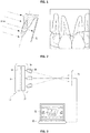
- FIG. 1 is a view showing principle of intra-oral X-ray radiography mainly used in the dental field, and an intra-oral X-ray image according to the intra-oral X-ray radiography.
- intra-oral X-ray radiography is an X-ray radiography technology for obtaining an X-ray image of a limited field of view of a subject, and is performed as follows: an X-ray sensor S is placed inside the subject's mouth; and X-rays are irradiated from an X-ray generation apparatus outside the mouth to the X-ray sensor S, thereby obtaining an X-ray image of a tooth and surrounding tissue that is disposed between the X-ray generation apparatus and the X-ray sensor S.
- the intra-oral X-ray image has advantages of low distortion, excellent resolution and sharpness, and relatively low radiation exposure, so it is mainly used for implant treatment or endodontic treatment requiring high resolution.
- the conventional intra-oral X-ray image is a two-dimensional transmission image, in which results of X-ray attenuation by all the substances including a tooth and surrounding tissue, namely a field of view, that exist between the X-ray generation apparatus and the X-ray sensor S are superimposed on a two-dimensional plane defined as the incident surface of the X-ray sensor S.
- a depth of a desired portion such as s focus
- CT scans are additionally performed to obtain a three-dimensional X-ray image of the field of view or diagnosis is made based entirely on the empirical knowledge of the radiologist.
- the overall length of time and procedures are complicated and subject fatigue is increased, as well as a serious problem of unnecessarily increasing radiation exposure, and in the latter case, there is a deviation of diagnostic results according to the personal experience of the radiologist, and there is a high possibility of subjective judgment, which lowers the reliability of diagnosis.
- US 2013/294666 B1 discloses a digital x-ray unit is arranged to provide transmission of x-ray energy at a series of determined angles and perspectives.
- the transmission of x-ray energy may be captured as series of two-dimensional digital x-ray images, and provided to a processing environment.
- a three-dimensional radiographic image representation may be created from the series of two-dimensional digital x-ray images, and provide for display in various three-dimensional display environments.
- Suitable three-dimensional display environments include a stereoscopic display provided on a three-dimensional electronic display unit, and a virtual three-dimensional environment simulated with a software user interface provided on a two-dimensional electronic display unit.
- US 2009/185660 A1 discloses a multiple spot x-ray generator is provided that includes a plurality of electron generators.
- Each electron generator includes an emitter element to emit an electron beam, a meshed grid adjacent each emitter element to enhance an electric field at a surface of the emitter element, and a focusing element positioned to receive the electron beam from each of the emitter elements and focus the electron beam to form a focal spot on a shielded target anode, the shielded target anode structure producing an array of x-ray focal spots when impinged by electron beams generated by the plurality of electron generators.
- the plurality of electron generators are arranged to form an electron generator matrix that includes activation connections electrically connected to the plurality of electron generators, wherein each electron generator is connected to a pair of the activation connections to receive an electric potential therefrom.
- an object of the present invention is to provide a specific method of not only providing a two-dimensional transmission image (hereinafter, referred to as 'transmission image') but also a three-dimensional tomosynthesis image (hereinafter, referred to as 'tomosynthesis image') and a three-dimensional CT (Computed Tomography) image (hereinafter, referred to as 'CT image') of a tooth and surrounding tissue inside a subject's mouth, namely a field of view by acquiring three-dimensional location information on an arbitrary point within the field of view, particularly, depth information about the direction of X-rays based on the result of intra-oral X-ray radiography.
- 'transmission image' a three-dimensional tomosynthesis image
- 'CT image' Computed Tomography
- a specific object of the present invention is to provide an X-ray generation apparatus for intra-oral X-ray imaging and an intra-oral X-ray imaging system including the same, which are capable of providing a transmission image, a tomosynthesis image, and a CT image of a tooth and surrounding tissue inside a mouth.
- an X-ray generation apparatus for intra-oral X-ray with the features of claim 1.
- Each of the plurality of X-ray sources may irradiate X-rays to form a unit frame of X-ray image of the object.
- Each of the X-ray sources may include an X-ray source module adopting an electric field emission type nanostructure emitter.
- the plurality of X-ray sources may irradiate the X-rays at a rate of 1 to 20 frames per second.
- An X-ray generation apparatus for intra-oral X-ray imaging according to the present invention and an intra-oral X-ray imaging system including the same are capable of providing not only a two-dimensional transmission image but also a three-dimensional tomosynthesis image and a three-dimensional CT image of a tooth and surrounding tissue inside a subject's mouth, namely a field of view. Accordingly, it is possible to identify three-dimensional location information on an arbitrary point within the field of view, particularly, depth information about the direction of X-rays based on the result of intra-oral X-ray radiography without performing additional X-ray radiography, such as computed tomography.
- the present invention without large-sized equipment that includes an X-ray generation apparatus and an X-ray detector rotating around the subject's head, it is possible to obtain various types of X-ray radiography images including a CT image of a part that needs medical treatment. Meanwhile, by using a small-sized intraoral x-ray sensor that is disposed inside the mouth, it is possible dramatically reduce X-ray exposure to the subject compared to the high-quality imaging result. Thereby, diagnostic accuracy can be greatly improved without significant burden on X-ray exposure in the dental field.
- FIG. 2 shows a schematic configuration of an intra-oral X-ray imaging system according to the present invention.
- an intra-oral X-ray imaging system includes: an X-ray generation apparatus 10 configured to irradiate X-rays to a tooth and surrounding tissue, namely a field of view inside a subject's mouth, from outside the mouth; an X-ray sensor apparatus 20 disposed inside the subject's mouth to face the X-ray generation apparatus with the field of view therebetween, and configured to detect the X-rays having penetrated through the field of view; and an image processing apparatus 30 configured to realize an X-ray image of the field of view based on X-rays projection data, namely a detection result of the X-ray sensor apparatus 20.
- the intra-oral X-ray imaging system is characterized in that: the X-ray generation apparatus 10 is configured to irradiate a plurality of X-rays to the field of view at the same angle or different angles; the X-ray sensor apparatus 20 is configured to detect the plurality of X-rays having penetrated through the field of view at the same angle or different angles; and the image processing apparatus 30 is configured to produce and display at least one X-ray image of a two-dimensional transmission image, a tomosynthesis image, and a three-dimensional CT image of the field of view, based on the plurality of X-rays projection data at the same angle or different angles, namely a detection result of the X-ray sensor apparatus 20.
- the X-ray generation apparatus 10 irradiates the X-rays at the same angle or different angles at a rate of 1 to 20 frames per second, and the X-ray sensor apparatus 20 detects the X-rays at a rate of 1 to 20 frames per second.
- the X-ray generation apparatus 10 includes: a plurality of X-ray sources 16 configured to respectively irradiate X-rays at the same angle or different angles to the X-ray sensor apparatus 20; a controller 12 configured to supply driving power and control signals for driving the X-ray sources 16; and a power supply 14 configured to supply driving power for the X-ray sources 16 and the controller 12, wherein the above elements of the X-ray generation apparatus are properly mounted in a body H.
- a side of the body H is provided with a plurality of cones 18, in which some or all of the plurality of X-ray sources 16 is mounted one-to-one, and the cones 18 serves to substantially adjust the direction of the X-rays of the X-ray sources 16.
- FIG. 3 shows an X-ray generation apparatus according to an embodiment of the present invention. See also FIG. 2 .
- the controller 12 and the power supply 14 of the X-ray sensor apparatus 20 may be mounted in the body H, and a side of the body H, for example, a front surface thereof may be provided with the plurality of cones 18. Further, a side of the body H, for example, an upper surface thereof may be provided with a display device D and at least one button B as a user interface for inputting a user operation signal for driving and controlling the X-ray sources 16.
- the plurality of X-ray sources 16 is mounted one-to-one in the plurality of cones 18, wherein as shown in left view a, the plurality of cones 18 are connected to the body H by ball joints (not shown) and the angles may be individually adjusted.
- each of the cones 18 and the X-ray sources 16 may be detachable from the body H via a cable C connecting the X-ray sources 16 and the controller 12. Also in this case, it is possible to adjust the direction and angle of the X-rays irradiated by the respective X-ray sources 16 by adjusting the position and angle of the cones 18.
- the plurality of cones 18 may be provided with an adjusting means, such as a collimator, configured to adjust an irradiation range of the X-rays of the X-ray sources 16 mounted one-to-one in the cones.
- the power supply 14 may include a battery or a power cable connected to an external power source.
- the X-ray sources 16 are modularized and detachably coupled to the body H as an X-ray source module.
- the X-ray sources are coupled and separated through a coupling structure including a plurality of connection terminal electrodes such as a power terminal and a control signal terminal for power and control signal supply.
- the coupling structure is mechanically configured such that an angle thereof is adjusted while the X-ray source module is mounted thereto.
- the X-ray generation apparatus 10 may individually drive the plurality of X-ray sources 16 using the power and the control signals of the power supply 14 and the controller 12 according to a user operation signal input to the at least one button B or control signals from the image processing apparatus, thereby irradiating a plurality of X-rays, and a plurality of X-rays at different angles may be irradiated toward the X-ray sensor apparatus 20 through the adjustment of the angle and position of the cones 18.
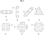
- FIG. 4 shows an example of an arrangement of the X-ray sources of the X-ray generation apparatus according to an embodiment of the present invention. The cones are omitted for convenience.
- the three X-ray sources 16 of the X-ray generation apparatus may be arranged horizontally ( FIG. 4a ), vertically ( FIG. 4b ), diagonally ( FIG. 4c ), or triangularly ( FIG. 4d ).
- the four X-ray sources 16 may be arranged in a quadrangular shape ( FIG. 4e ), a cruciform intersecting vertically and horizontally ( FIG. 4f ), or an X-shape crossing in the left and right diagonal ( FIG. 4g ).
- the plurality of X-ray sources 16 provided in the X-ray generation apparatus 10 are electric field emission type X-ray sources using a nanostructure emitter, such as a CNT (carbon nanotube).
- a nanostructure emitter such as a CNT (carbon nanotube).
- an electric field emission type X-ray source apparatus can obtain high-efficiency X-rays with low power, pulse drive is possible since an operation period is short, and it is small size and light weight. Accordingly, it is suitable for the X-ray generation apparatus 10 of the present invention, in which the plurality of X-ray sources 16 are provided in a single apparatus and individually driven. Further, in this case, the X-ray generation apparatus 10 is capable of irradiating X-rays at a rate of 1 to 20 frames per second.
- FIG. 5 shows performing radiography using the X-ray generation apparatus according to an embodiment of the present invention.
- the X-ray generation apparatus 10 of the intra-oral X-ray imaging system is configured such that the plurality of X-ray sources 16 irradiates X-rays at a same angle or different angles to the field of view, more specifically, to the X-ray sensor apparatus 20 disposed to face the X-ray generation apparatus with the field of view therebetween, on a frame-by-frame basis, and the X-ray sensor apparatus 20 detects the X-rays having penetrated through the field of view at the same angle or different angles on a frame-by-frame basis.
- the left X-ray source 16A irradiates X-rays that can form a one-frame transmission image, to the X-ray sensor apparatus 20 disposed behind the field of view for a predetermined time.
- the X-ray sensor apparatus 20 transmits projection data A of the frame to the image processing apparatus.
- the middle X-ray source 16B irradiates X-rays again that can form a one-frame transmission image.
- the X-ray sensor apparatus 20 transmits projection data B of the frame to the image processing apparatus, and this process is repeated for the right X-ray source 16C to acquire projection data C.
- the X-ray sensor apparatus 20 may transmit X-ray projection data to the image processing apparatus at a rate of 1 to 20 frames per second, whereby the image processing apparatus may display a real-time X-ray video clip.
- the image processing apparatus 30 of the intra-oral X-ray imaging system is configured to construct an image expressed in gray scale by using an X-ray detection result transmitted on a frame-by-frame basis from the X-ray sensor apparatus 20, and produce and display at least one of a two-dimensional transmission image, a tomosynthesis image, and a three-dimensional CT image of the field of view.
- the image processing apparatus 30 may include a monitor 32 configured to display the X-ray image.
- the X-ray detection result of the X-ray sensor apparatus 20 may be transmitted to the image processing apparatus 30 by wire or wirelessly.
- a two-dimensional X-ray projection data acquired by irradiating X-rays at the same angle or different angles, that is, one of the projection data A, B, and C may be displayed as a two-dimensional transmission image of the field of view.
- a two-dimensional transmission image that is constructed by superimposing the projection data A, B, and C in a plane may be displayed.
- a tomosynthesis image may be constructed through a publicly known three-dimensional tomosynthesis image algorithm by using two-dimensional projection data at different angles from each other, that is, the projection data A, B, and C.
- a three-dimensional tomosynthesis image of a field of view by reconstructing data through SAA (Shift And ADD) algorithm that obtains a tomographic image by backprojecting each of the two-dimensional projection data to a plane of interest (POI).
- SAA Shift And ADD
- POI plane of interest
- a user can identify a conventional intra-oral X-ray image or the three-dimensional tomosynthesis image reflecting the depth information on an arbitrary point depending on the purpose.
- a three-dimensional image may be provided by reconstructing the plurality of projection data acquired on a frame-by-frame basis through reconstruction algorithm.
- projection data acquired from more diverse angles than the tomosynthesis image may be required.
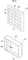
- FIG. 6 shows an X-ray generation apparatus according to an embodiment of the present invention.
- the plurality of X-ray sources is arranged in an array on a single body 101H, and includes a plurality of X-ray source elements 160 using an electric field emission type nanostructure emitter.
- Each of the plurality of X-ray sources is constituted by X-ray source element groups G1, G2, and G3 each including at least one X-ray source element 160.
- the plurality of X-ray source element groups G1, G2, and G3 may be driven in groups.
- a controller provided in the body 101H of the X-ray generation apparatus 101 according to the embodiment of the present invention may drive the plurality of X-ray source elements 160 arranged in an array, individually or in groups.
- the driven X-ray source element groups G1, G2, and G3 irradiate X-rays to the X-ray sensor apparatus 20 in the same direction or different directions, to respectively form a one-frame X-ray transmission image.
- the plurality of X-ray source elements 160 and the X-ray sensor apparatus 20 constitutes a Multi-Source Inverse-Geometry CT system having a plurality of scattered focal spots, whereby it is possible to reconstruct a three-dimensional CT image of the field of view (FOV) that is larger than the sensor area of the X-ray sensor apparatus 20.
- FOV field of view
- FIG. 7 schematically shows a cross section of an X-ray sensor apparatus according to an embodiment of the present invention.
- the X-ray sensor apparatus 20 includes: an X-ray sensor 22 configured to detect X-rays; and a readout circuit 24 configured to read out a detection result of the x-ray sensor 22 to the image processing apparatus 30.
- the X-ray sensor apparatus 20 reads out the X-ray detection result of the x-ray sensor 22 on a frame-by-frame basis.
- the readout circuit 24 may divide the X-ray sensor 22 into a plurality of sections, and may read out the X-ray detection result on a multi-channel basis through a separate channel for each section.
- FIG. 8 schematically shows the concept of a multi-channel readout of the X-ray sensor apparatus according to an embodiment of the present invention.
- the readout circuit 24 may divide an incident surface of the X-ray sensor 22 into at least two sections, and allocate an individual readout channel to each section, thereby simultaneously reading out each channel.
- the embodiment is configured such that the incident surface of the X-ray sensor 22 is divided into three sections 221, 222, and 223, and three separate readout channels ch1, ch2, and ch3 are respectively allocated to each section, thereby simultaneously reading out each channel.
- the X-ray sensor apparatus 20 shortens the readout time of one frame by one third, thereby detecting and reading out X-rays irradiated on a frame-by-frame basis from the at least two X-ray sources, at high speed.
- two or more X-ray sensors 22 or X-ray sensor apparatuses 20 are arranged along a back and forth direction with respect to the x-ray generation apparatus, wherein a predetermined filter may be disposed between the two different X-ray sensors 22 or X-ray sensor apparatuses 20.
- a predetermined filter may be disposed between the two different X-ray sensors 22 or X-ray sensor apparatuses 20.
- X-ray detection results of different energy levels which are gradually decreased by the filter may be obtained, and depending on the energy levels, X-ray images optimized for soft tissues such as skin and x-ray images optimized for hard tissues such as teeth may be obtained, which will be easily understood by those skilled in the art even though there are no separate drawings.
- the X-ray sensor apparatus 20 may be a so-called flexible sensor or a bendable sensor that is bent within a predetermined range according to the shape of a tooth and surrounding tissues in the mouth, whereby it is possible to alleviate the pain that a patient may experience during the X-ray radiography process.
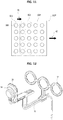
- FIG. 9 shows X-ray generation apparatuses according to various embodiments of the present invention.
- upper view a shows an example of an X-ray generation apparatus 102 including a plurality of X-ray source elements 160 arranged in a quadrangular array on the body 102H; and lower view b shows an example of an X-ray generation apparatus 103 further including a guide frame 103F configured to guide a single body 103M to move within a predetermined range.
- a plurality of X-ray source elements 160 for example, twenty five X-ray source elements 160 are arranged in a 5x5 matrix. These are grouped into one or more than one to form X-ray source element groups GA and GB, wherein a vertically long group, like the left X-ray source element group GA, may be formed, or a square-shaped group, like the upper X-ray source element group GB, may be formed.
- the array form of the X-ray source element groups is not limited to these, and may be variously grouped. Further, the X-ray source element groups are not fixed, but may be set to vary according to the position and size of the field of view.
- a plurality of X-ray source elements 160 are arranged vertically in a single body 103M, and during a series of X-ray radiography processes, the body 103M itself moves along the guide frame 103F to irradiate X-rays at various angles.
- the plurality of X-ray source elements 160 may be individually driven or may be driven in groups by grouping two or more source elements in a group.
- the plurality of X-ray source elements 160 are configured to irradiate X-rays at various angles while moving with respect to the body 103M, and to achieve this, an additional guide frame is provided in the body 103M to allow the plurality of X-ray source elements 160 to be moved.
- FIG. 10 shows performing radiography using an X-ray generation apparatus according to an embodiment of the present invention.
- an X-ray generation apparatus 10M according to the embodiment of FIG. 10 and an intra-oral X-ray imaging system including the same are common to the embodiment shown in FIG. 2 or 5 in that it has a plurality of X-ray sources 16 arranged at various positions on one body H of the X-ray generation apparatus 10M, but the X-ray generation apparatus 10M according to the embodiment of the present invention is different from the embodiment shown in FIG. 2 or 5 in that it is configured to move along a predetermined trajectory R during a series of X-ray radiography processes.
- the predetermined trajectory R may be, for example, an arc-shaped trajectory, but is not limited thereto.
- the predetermined trajectory R may be substantially realized by rails or various types of guide frames that guide the path of the body H.
- the X-ray generation apparatus 10M according to the embodiment of the present invention and the intra-oral X-ray imaging system are configured to move plurality of X-ray sources 16 and/or the body H in parallel with driving a plurality of X-ray sources 16 while driving the plurality of X-ray sources 16, whereby it is possible to obtain X-rays projection data of more frames imaged at more varying angles during a series of intra-oral X-ray radiographies. Accordingly, it is possible to provide a high-quality X-ray CT image with a small-sized intraoral x-ray sensor apparatus 200.
- the X-ray sensor apparatus 200 may include a so-called flexible sensor or a bendable sensor that is bent within a predetermined range according to the shape of a tooth and surrounding tissues in the mouth, or may include a curved X-ray sensor curved at a predetermined curvature.
- the curved X-ray sensor it may be variously provided with various curvatures depending on the position where the X-ray sensor apparatus 200 is mainly disposed in the mouth. Thereby, it is possible to alleviate the pain that a patient may experience during the X-ray radiography process.
- FIG. 11 shows an X-ray generation apparatus according to an embodiment of the present invention.
- An X-ray generation apparatus 102M according to the embodiment of the present invention is similar to the apparatus according to the embodiment shown in FIG. 7a , but is different therefrom in that a body 102H of the X-ray generation apparatus 102M is configured to be movable along a predetermined trajectory.
- X-ray projection data of a frame corresponding to each group GC1, GC2 is acquired in the X-ray sensor apparatus while driving X-ray source element groups GC1 and GC2, each of which is constituted by one or a plurality of X-ray source elements 160, in a direction of arrow A1, and at the same time, it is possible to move the body 102H in a direction of arrow A2.
- the driving of the X-ray source element groups GC1 and GC2 and the movement of the body 102H may be performed at the same time, and the driving of the entire group and the movement of the body 102H may be repeatedly performed alternately.
- the plurality of X-ray source element groups GC1 and GC2 may be grouped such that each group shares some of the X-ray source elements 160. It is preferred that a plurality of X-ray source element groups is configured such that the X-ray irradiation range of one group covers at least an area of a corresponding X-ray sensor. Further, although not shown in the drawing, a collimator may be provided in the path of X-rays of the X-ray generation apparatus, which is configured to adjust the irradiation range of the X-rays that are irradiated by driving each group such to cover an area of the X-ray sensor, respectively.
- FIG. 12 shows an example of a guide holder for intra-oral X-ray radiography.
- a guide holder applied to an intra-oral X-ray imaging system includes: at least two source fasteners 52 configured to allow at least two X-ray sources to be fastened one-to-one thereto; a sensor fastener 54 configured to fasten an X-ray sensor apparatus 20; and a loader 56 configured to connect the at least two source fasteners 52 and the sensor fastener 54 to face each other with a predetermined interval.
- the at least two source fasteners 52 may exhibit an arrangement relation, in which an optimal two-dimensional transmission image and a three-dimensional tomosynthesis image can be obtained, in consideration of the distance between the source fasteners or the distance to the sensor fastener 54.
- the cones 18 of the X-ray generation apparatus 10 shown in FIG. 3 are respectively inserted into each of the at least two source fasteners 52 such that the positions and angles thereof are fixed, and on the other hand, when he X-ray sensor apparatus 20 is fastened to the sensor fastener 54, the at least two X-ray sources 16 and the X-ray sensor apparatus 20 have the optimal arrangement relation, in which a two-dimensional transmission image and a three-dimensional tomosynthesis image may be obtained according to the purpose.
- the sensor fastener 54 and the X-ray sensor apparatus 20 are aligned at desired positions in the subject's mouth, and then X-rays on a frame-by-frame basis are sequentially irradiated from the at least two X-ray sources 16, whereby it is possible to obtain an accurate two-dimensional transmission image and a three-dimensional tomosynthesis image of the field of view at all times.
- the detailed shape of the guide holder such as the loader 56
- the position and quantity of the source fastener 52 may be variously modified according to the positions and quantity of the cones 18 and the X-ray sources 16 of the X-ray generation apparatus 10.
- the present invention may be used in dental or medical X-ray diagnostic equipment as well as industrial non-destructive testing equipment.
Description
- The present invention relates generally to an intra-oral X-ray radiography. More particularly, the present invention relates to an X-ray generation apparatus for intra-oral X-ray imaging in which various types of images of a tooth and surrounding tissue, namely a field of view, can be obtained.
- As is well known, X-rays are attenuated according to an X-ray attenuation coefficient, such as photoelectric effect, Compton scattering, and the like, of a substance placed in a path of the X-rays.
- X-ray radiography is a radiography method using straightness and attenuation of X-rays, and based on the amount of attenuation accumulated in the course of the X-rays passing through a field of view, it provides an X-ray image of the internal structure of the field of view. To achieve this, an X-ray imaging system includes: an X-ray generation apparatus configured to irradiate X-rays to a field of view; an X-ray sensor disposed to face the X-ray generation apparatus with the field of view therebetween, and configured to detect X-rays that have penetrated through the field of view; and an image processing apparatus configured to construct a gray-level X-ray image of an internal structure of the field of view by using X-ray projection data, as a detection result detected by the X-ray sensor.
- Meanwhile, in recent years, X-ray radiography has been rapidly evolving into DR (Digital Radiography) using digital sensors due to the development of semiconductor and information processing technologies, whereby image processing technology has also been developed and is used in various ways according to the purpose and application field.
- As an example,
FIG. 1 is a view showing principle of intra-oral X-ray radiography mainly used in the dental field, and an intra-oral X-ray image according to the intra-oral X-ray radiography. - As shown in the drawing, intra-oral X-ray radiography is an X-ray radiography technology for obtaining an X-ray image of a limited field of view of a subject, and is performed as follows: an X-ray sensor S is placed inside the subject's mouth; and X-rays are irradiated from an X-ray generation apparatus outside the mouth to the X-ray sensor S, thereby obtaining an X-ray image of a tooth and surrounding tissue that is disposed between the X-ray generation apparatus and the X-ray sensor S. The intra-oral X-ray image has advantages of low distortion, excellent resolution and sharpness, and relatively low radiation exposure, so it is mainly used for implant treatment or endodontic treatment requiring high resolution.
- However, the conventional intra-oral X-ray image is a two-dimensional transmission image, in which results of X-ray attenuation by all the substances including a tooth and surrounding tissue, namely a field of view, that exist between the X-ray generation apparatus and the X-ray sensor S are superimposed on a two-dimensional plane defined as the incident surface of the X-ray sensor S. Thus, with the intra-oral X-ray image alone, it is impossible to identify a depth of a desired portion, such as s focus, within the area of the X-ray image, that is, relative positional relationship of the path of the X-rays.
- Accordingly, for more accurate diagnosis, such as a three-dimensional location of a desired portion of the intra-oral X-ray image, CT scans are additionally performed to obtain a three-dimensional X-ray image of the field of view or diagnosis is made based entirely on the empirical knowledge of the radiologist. However, in the former case, the overall length of time and procedures are complicated and subject fatigue is increased, as well as a serious problem of unnecessarily increasing radiation exposure, and in the latter case, there is a deviation of diagnostic results according to the personal experience of the radiologist, and there is a high possibility of subjective judgment, which lowers the reliability of diagnosis.
-
US 2013/294666 B1 discloses a digital x-ray unit is arranged to provide transmission of x-ray energy at a series of determined angles and perspectives. The transmission of x-ray energy may be captured as series of two-dimensional digital x-ray images, and provided to a processing environment. A three-dimensional radiographic image representation may be created from the series of two-dimensional digital x-ray images, and provide for display in various three-dimensional display environments. Suitable three-dimensional display environments include a stereoscopic display provided on a three-dimensional electronic display unit, and a virtual three-dimensional environment simulated with a software user interface provided on a two-dimensional electronic display unit. - Moreover,
US 2009/185660 A1 discloses a multiple spot x-ray generator is provided that includes a plurality of electron generators. Each electron generator includes an emitter element to emit an electron beam, a meshed grid adjacent each emitter element to enhance an electric field at a surface of the emitter element, and a focusing element positioned to receive the electron beam from each of the emitter elements and focus the electron beam to form a focal spot on a shielded target anode, the shielded target anode structure producing an array of x-ray focal spots when impinged by electron beams generated by the plurality of electron generators. The plurality of electron generators are arranged to form an electron generator matrix that includes activation connections electrically connected to the plurality of electron generators, wherein each electron generator is connected to a pair of the activation connections to receive an electric potential therefrom. - Accordingly, the present invention has been made keeping in mind the above problems occurring in the related art, and an object of the present invention is to provide a specific method of not only providing a two-dimensional transmission image (hereinafter, referred to as 'transmission image') but also a three-dimensional tomosynthesis image (hereinafter, referred to as 'tomosynthesis image') and a three-dimensional CT (Computed Tomography) image (hereinafter, referred to as 'CT image') of a tooth and surrounding tissue inside a subject's mouth, namely a field of view by acquiring three-dimensional location information on an arbitrary point within the field of view, particularly, depth information about the direction of X-rays based on the result of intra-oral X-ray radiography.
- To achieve this, a specific object of the present invention is to provide an X-ray generation apparatus for intra-oral X-ray imaging and an intra-oral X-ray imaging system including the same, which are capable of providing a transmission image, a tomosynthesis image, and a CT image of a tooth and surrounding tissue inside a mouth.
- In order to achieve the above object, according to some aspect of the present invention, there is provided an X-ray generation apparatus for intra-oral X-ray with the features of
claim 1. - Each of the plurality of X-ray sources may irradiate X-rays to form a unit frame of X-ray image of the object.
- Each of the X-ray sources may include an X-ray source module adopting an electric field emission type nanostructure emitter.
- The plurality of X-ray sources may irradiate the X-rays at a rate of 1 to 20 frames per second.
- An X-ray generation apparatus for intra-oral X-ray imaging according to the present invention and an intra-oral X-ray imaging system including the same are capable of providing not only a two-dimensional transmission image but also a three-dimensional tomosynthesis image and a three-dimensional CT image of a tooth and surrounding tissue inside a subject's mouth, namely a field of view. Accordingly, it is possible to identify three-dimensional location information on an arbitrary point within the field of view, particularly, depth information about the direction of X-rays based on the result of intra-oral X-ray radiography without performing additional X-ray radiography, such as computed tomography.
- Further, according to the present invention, without large-sized equipment that includes an X-ray generation apparatus and an X-ray detector rotating around the subject's head, it is possible to obtain various types of X-ray radiography images including a CT image of a part that needs medical treatment. Meanwhile, by using a small-sized intraoral x-ray sensor that is disposed inside the mouth, it is possible dramatically reduce X-ray exposure to the subject compared to the high-quality imaging result. Thereby, diagnostic accuracy can be greatly improved without significant burden on X-ray exposure in the dental field.
-
-
FIG. 1 shows principle of a general intra-oral X-ray radiography and an intra-oral X-ray image; -
FIG. 2 shows a schematic configuration of an intra-oral X-ray imaging system according to the present invention; -
FIG. 3 shows an X-ray generation apparatus according to an embodiment of the present invention; -
FIG. 4 shows an example of an arrangement of X-ray sources of the X-ray generation apparatus according to an embodiment of the present invention; -
FIG. 5 shows performing radiography using the X-ray generation apparatus according to an embodiment of the present invention; -
FIG. 6 shows an X-ray generation apparatus according to an embodiment of the present invention; -
FIG. 7 schematically shows a cross section of an X-ray sensor apparatus according to an embodiment of the present invention; -
FIG. 8 schematically shows the concept of a multi-channel readout of the X-ray sensor apparatus according to an embodiment of the present invention; -
FIG. 9 shows X-ray generation apparatuses according to various embodiments of the present invention; -
FIG. 10 shows performing radiography using an X-ray generation apparatus according to an embodiment of the present invention; -
FIG. 11 shows an X-ray generation apparatus according to an embodiment of the present invention; and -
FIG. 12 shows an example of a guide holder for intra-oral X-ray radiography. - Hereinbelow, preferred embodiments of the present invention will be described in detail with reference to the accompanying drawings.
-
FIG. 2 shows a schematic configuration of an intra-oral X-ray imaging system according to the present invention. - As shown in the drawing, an intra-oral X-ray imaging system according to the present invention includes: an
X-ray generation apparatus 10 configured to irradiate X-rays to a tooth and surrounding tissue, namely a field of view inside a subject's mouth, from outside the mouth; anX-ray sensor apparatus 20 disposed inside the subject's mouth to face the X-ray generation apparatus with the field of view therebetween, and configured to detect the X-rays having penetrated through the field of view; and animage processing apparatus 30 configured to realize an X-ray image of the field of view based on X-rays projection data, namely a detection result of theX-ray sensor apparatus 20. - Here, particularly, the intra-oral X-ray imaging system according to the present invention is characterized in that: the
X-ray generation apparatus 10 is configured to irradiate a plurality of X-rays to the field of view at the same angle or different angles; theX-ray sensor apparatus 20 is configured to detect the plurality of X-rays having penetrated through the field of view at the same angle or different angles; and theimage processing apparatus 30 is configured to produce and display at least one X-ray image of a two-dimensional transmission image, a tomosynthesis image, and a three-dimensional CT image of the field of view, based on the plurality of X-rays projection data at the same angle or different angles, namely a detection result of theX-ray sensor apparatus 20. - In this case, preferably, the
X-ray generation apparatus 10 irradiates the X-rays at the same angle or different angles at a rate of 1 to 20 frames per second, and theX-ray sensor apparatus 20 detects the X-rays at a rate of 1 to 20 frames per second. - Detailed description of main elements of the intra-oral X-ray imaging system according to the present invention is as follows.
- The
X-ray generation apparatus 10 includes: a plurality ofX-ray sources 16 configured to respectively irradiate X-rays at the same angle or different angles to theX-ray sensor apparatus 20; acontroller 12 configured to supply driving power and control signals for driving theX-ray sources 16; and apower supply 14 configured to supply driving power for theX-ray sources 16 and thecontroller 12, wherein the above elements of the X-ray generation apparatus are properly mounted in a body H. - Here, preferably, a side of the body H is provided with a plurality of
cones 18, in which some or all of the plurality ofX-ray sources 16 is mounted one-to-one, and thecones 18 serves to substantially adjust the direction of the X-rays of theX-ray sources 16. -
FIG. 3 shows an X-ray generation apparatus according to an embodiment of the present invention. See alsoFIG. 2 . - As shown in the drawing, the
controller 12 and thepower supply 14 of theX-ray sensor apparatus 20 may be mounted in the body H, and a side of the body H, for example, a front surface thereof may be provided with the plurality ofcones 18. Further, a side of the body H, for example, an upper surface thereof may be provided with a display device D and at least one button B as a user interface for inputting a user operation signal for driving and controlling theX-ray sources 16. - Further, some or all of the plurality of
X-ray sources 16 is mounted one-to-one in the plurality ofcones 18, wherein as shown in left view a, the plurality ofcones 18 are connected to the body H by ball joints (not shown) and the angles may be individually adjusted. As another example, as shown in right view b, each of thecones 18 and theX-ray sources 16 may be detachable from the body H via a cable C connecting theX-ray sources 16 and thecontroller 12. Also in this case, it is possible to adjust the direction and angle of the X-rays irradiated by therespective X-ray sources 16 by adjusting the position and angle of thecones 18. For reference, the plurality ofcones 18 may be provided with an adjusting means, such as a collimator, configured to adjust an irradiation range of the X-rays of theX-ray sources 16 mounted one-to-one in the cones. Thepower supply 14 may include a battery or a power cable connected to an external power source. - According to the invention, the
X-ray sources 16 are modularized and detachably coupled to the body H as an X-ray source module. In this case, the X-ray sources are coupled and separated through a coupling structure including a plurality of connection terminal electrodes such as a power terminal and a control signal terminal for power and control signal supply. The coupling structure is mechanically configured such that an angle thereof is adjusted while the X-ray source module is mounted thereto. - As a result of this configuration, the
X-ray generation apparatus 10 may individually drive the plurality ofX-ray sources 16 using the power and the control signals of thepower supply 14 and thecontroller 12 according to a user operation signal input to the at least one button B or control signals from the image processing apparatus, thereby irradiating a plurality of X-rays, and a plurality of X-rays at different angles may be irradiated toward theX-ray sensor apparatus 20 through the adjustment of the angle and position of thecones 18. - Meanwhile, although the three
cones 18 and theX-ray sources 16 are disposed horizontally inFIG. 3 , the positions and quantity of thecones 18 and theX-ray sources 16 may be freely adjusted according to the purpose.FIG. 4 shows an example of an arrangement of the X-ray sources of the X-ray generation apparatus according to an embodiment of the present invention. The cones are omitted for convenience. - As shown in the drawings, the three
X-ray sources 16 of the X-ray generation apparatus may be arranged horizontally (FIG. 4a ), vertically (FIG. 4b ), diagonally (FIG. 4c ), or triangularly (FIG. 4d ). Alternatively, the fourX-ray sources 16 may be arranged in a quadrangular shape (FIG. 4e ), a cruciform intersecting vertically and horizontally (FIG. 4f ), or an X-shape crossing in the left and right diagonal (FIG. 4g ). However, these are only a few examples, and the positions and quantity of theX-ray sources 16 may be variously modified according to the purpose. - Meanwhile, preferably, the plurality of
X-ray sources 16 provided in theX-ray generation apparatus 10 are electric field emission type X-ray sources using a nanostructure emitter, such as a CNT (carbon nanotube). As is well known, an electric field emission type X-ray source apparatus can obtain high-efficiency X-rays with low power, pulse drive is possible since an operation period is short, and it is small size and light weight. Accordingly, it is suitable for theX-ray generation apparatus 10 of the present invention, in which the plurality ofX-ray sources 16 are provided in a single apparatus and individually driven. Further, in this case, theX-ray generation apparatus 10 is capable of irradiating X-rays at a rate of 1 to 20 frames per second. -
FIG. 5 shows performing radiography using the X-ray generation apparatus according to an embodiment of the present invention. - As described above, particularly, the
X-ray generation apparatus 10 of the intra-oral X-ray imaging system according to the present invention is configured such that the plurality ofX-ray sources 16 irradiates X-rays at a same angle or different angles to the field of view, more specifically, to theX-ray sensor apparatus 20 disposed to face the X-ray generation apparatus with the field of view therebetween, on a frame-by-frame basis, and theX-ray sensor apparatus 20 detects the X-rays having penetrated through the field of view at the same angle or different angles on a frame-by-frame basis. As shown in the drawing, in the case of providing threeX-ray sources left X-ray source 16A irradiates X-rays that can form a one-frame transmission image, to theX-ray sensor apparatus 20 disposed behind the field of view for a predetermined time. Here, theX-ray sensor apparatus 20 transmits projection data A of the frame to the image processing apparatus. Then, themiddle X-ray source 16B irradiates X-rays again that can form a one-frame transmission image. TheX-ray sensor apparatus 20 transmits projection data B of the frame to the image processing apparatus, and this process is repeated for theright X-ray source 16C to acquire projection data C. - Meanwhile, preferably, the
X-ray sensor apparatus 20 may transmit X-ray projection data to the image processing apparatus at a rate of 1 to 20 frames per second, whereby the image processing apparatus may display a real-time X-ray video clip. - Referring back to
FIG. 2 , theimage processing apparatus 30 of the intra-oral X-ray imaging system according to the present invention is configured to construct an image expressed in gray scale by using an X-ray detection result transmitted on a frame-by-frame basis from theX-ray sensor apparatus 20, and produce and display at least one of a two-dimensional transmission image, a tomosynthesis image, and a three-dimensional CT image of the field of view. To achieve this, theimage processing apparatus 30 may include amonitor 32 configured to display the X-ray image. Meanwhile, the X-ray detection result of theX-ray sensor apparatus 20 may be transmitted to theimage processing apparatus 30 by wire or wirelessly. - When the
image processing apparatus 30 displays a transmission image, a two-dimensional X-ray projection data acquired by irradiating X-rays at the same angle or different angles, that is, one of the projection data A, B, and C may be displayed as a two-dimensional transmission image of the field of view. In some cases, a two-dimensional transmission image that is constructed by superimposing the projection data A, B, and C in a plane may be displayed. - When the
image processing apparatus 30 displays a tomosynthesis image, a tomosynthesis image may be constructed through a publicly known three-dimensional tomosynthesis image algorithm by using two-dimensional projection data at different angles from each other, that is, the projection data A, B, and C. For example, it is possible to display a three-dimensional tomosynthesis image of a field of view by reconstructing data through SAA (Shift And ADD) algorithm that obtains a tomographic image by backprojecting each of the two-dimensional projection data to a plane of interest (POI). A user can identify a conventional intra-oral X-ray image or the three-dimensional tomosynthesis image reflecting the depth information on an arbitrary point depending on the purpose. When theimage processing apparatus 30 displays a CT image, a three-dimensional image may be provided by reconstructing the plurality of projection data acquired on a frame-by-frame basis through reconstruction algorithm. However, to construct a CT image, projection data acquired from more diverse angles than the tomosynthesis image may be required. -
FIG. 6 shows an X-ray generation apparatus according to an embodiment of the present invention. - In the
X-ray generation apparatus 101 according to the embodiment of the present invention, the plurality of X-ray sources is arranged in an array on asingle body 101H, and includes a plurality ofX-ray source elements 160 using an electric field emission type nanostructure emitter. Each of the plurality of X-ray sources is constituted by X-ray source element groups G1, G2, and G3 each including at least oneX-ray source element 160. The plurality of X-ray source element groups G1, G2, and G3 may be driven in groups. In other words, a controller provided in thebody 101H of theX-ray generation apparatus 101 according to the embodiment of the present invention may drive the plurality ofX-ray source elements 160 arranged in an array, individually or in groups. In this case, the driven X-ray source element groups G1, G2, and G3 irradiate X-rays to theX-ray sensor apparatus 20 in the same direction or different directions, to respectively form a one-frame X-ray transmission image. - Meanwhile, in the drawing, for example, when a plurality of X-rays projection data is acquired through driving from an X-ray source element group G1 disposed on the left side of the
body 101H to an X-ray source element group on the right side thereof, an X-ray CT image may be reconstructed in the image processing apparatus by using the projection data. In this case, the plurality ofX-ray source elements 160 and theX-ray sensor apparatus 20 constitutes a Multi-Source Inverse-Geometry CT system having a plurality of scattered focal spots, whereby it is possible to reconstruct a three-dimensional CT image of the field of view (FOV) that is larger than the sensor area of theX-ray sensor apparatus 20. As a result of this configuration, it is possible to provide a CT image of a sufficient area of a field of view for dental diagnosis while alleviating the sensation of a foreign body by inserting the small-sizedX-ray sensor apparatus 20 into a subject's mouth. -
FIG. 7 schematically shows a cross section of an X-ray sensor apparatus according to an embodiment of the present invention. - As shown in the drawing, the
X-ray sensor apparatus 20 includes: anX-ray sensor 22 configured to detect X-rays; and areadout circuit 24 configured to read out a detection result of thex-ray sensor 22 to theimage processing apparatus 30. Here, theX-ray sensor apparatus 20 reads out the X-ray detection result of thex-ray sensor 22 on a frame-by-frame basis. Further, thereadout circuit 24 may divide theX-ray sensor 22 into a plurality of sections, and may read out the X-ray detection result on a multi-channel basis through a separate channel for each section. -
FIG. 8 schematically shows the concept of a multi-channel readout of the X-ray sensor apparatus according to an embodiment of the present invention. - The
readout circuit 24 may divide an incident surface of theX-ray sensor 22 into at least two sections, and allocate an individual readout channel to each section, thereby simultaneously reading out each channel. The embodiment is configured such that the incident surface of theX-ray sensor 22 is divided into threesections X-ray sensor apparatus 20 shortens the readout time of one frame by one third, thereby detecting and reading out X-rays irradiated on a frame-by-frame basis from the at least two X-ray sources, at high speed. - For reference, although not shown in the drawing, it is also possible that two or
more X-ray sensors 22 orX-ray sensor apparatuses 20 are arranged along a back and forth direction with respect to the x-ray generation apparatus, wherein a predetermined filter may be disposed between the twodifferent X-ray sensors 22 orX-ray sensor apparatuses 20. In this case, in each of theX-ray sensors 22 or theX-ray sensor apparatuses 20, X-ray detection results of different energy levels which are gradually decreased by the filter may be obtained, and depending on the energy levels, X-ray images optimized for soft tissues such as skin and x-ray images optimized for hard tissues such as teeth may be obtained, which will be easily understood by those skilled in the art even though there are no separate drawings. - Further, if necessary, the
X-ray sensor apparatus 20 may be a so-called flexible sensor or a bendable sensor that is bent within a predetermined range according to the shape of a tooth and surrounding tissues in the mouth, whereby it is possible to alleviate the pain that a patient may experience during the X-ray radiography process. -
FIG. 9 shows X-ray generation apparatuses according to various embodiments of the present invention. As shown in the drawings, upper view a shows an example of anX-ray generation apparatus 102 including a plurality ofX-ray source elements 160 arranged in a quadrangular array on thebody 102H; and lower view b shows an example of anX-ray generation apparatus 103 further including aguide frame 103F configured to guide asingle body 103M to move within a predetermined range. - Firstly, looking at the
X-ray generation apparatus 102 of view a, a plurality ofX-ray source elements 160, for example, twenty fiveX-ray source elements 160 are arranged in a 5x5 matrix. These are grouped into one or more than one to form X-ray source element groups GA and GB, wherein a vertically long group, like the left X-ray source element group GA, may be formed, or a square-shaped group, like the upper X-ray source element group GB, may be formed. The array form of the X-ray source element groups is not limited to these, and may be variously grouped. Further, the X-ray source element groups are not fixed, but may be set to vary according to the position and size of the field of view. - Next, looking at the
X-ray generation apparatus 103 of view b, a plurality ofX-ray source elements 160 are arranged vertically in asingle body 103M, and during a series of X-ray radiography processes, thebody 103M itself moves along theguide frame 103F to irradiate X-rays at various angles. Herein, the plurality ofX-ray source elements 160 may be individually driven or may be driven in groups by grouping two or more source elements in a group. Here, preferably, apart from movement of thebody 103M, the plurality ofX-ray source elements 160 are configured to irradiate X-rays at various angles while moving with respect to thebody 103M, and to achieve this, an additional guide frame is provided in thebody 103M to allow the plurality ofX-ray source elements 160 to be moved. -
FIG. 10 shows performing radiography using an X-ray generation apparatus according to an embodiment of the present invention. - As shown in the drawing, an
X-ray generation apparatus 10M according to the embodiment ofFIG. 10 and an intra-oral X-ray imaging system including the same are common to the embodiment shown inFIG. 2 or5 in that it has a plurality ofX-ray sources 16 arranged at various positions on one body H of theX-ray generation apparatus 10M, but theX-ray generation apparatus 10M according to the embodiment of the present invention is different from the embodiment shown inFIG. 2 or5 in that it is configured to move along a predetermined trajectory R during a series of X-ray radiography processes. Herein, the predetermined trajectory R may be, for example, an arc-shaped trajectory, but is not limited thereto. The predetermined trajectory R may be substantially realized by rails or various types of guide frames that guide the path of the body H. - The
X-ray generation apparatus 10M according to the embodiment of the present invention and the intra-oral X-ray imaging system are configured to move plurality ofX-ray sources 16 and/or the body H in parallel with driving a plurality ofX-ray sources 16 while driving the plurality ofX-ray sources 16, whereby it is possible to obtain X-rays projection data of more frames imaged at more varying angles during a series of intra-oral X-ray radiographies. Accordingly, it is possible to provide a high-quality X-ray CT image with a small-sized intraoralx-ray sensor apparatus 200. - Meanwhile, herein, the
X-ray sensor apparatus 200 may include a so-called flexible sensor or a bendable sensor that is bent within a predetermined range according to the shape of a tooth and surrounding tissues in the mouth, or may include a curved X-ray sensor curved at a predetermined curvature. In the case of the curved X-ray sensor, it may be variously provided with various curvatures depending on the position where theX-ray sensor apparatus 200 is mainly disposed in the mouth. Thereby, it is possible to alleviate the pain that a patient may experience during the X-ray radiography process. -
FIG. 11 shows an X-ray generation apparatus according to an embodiment of the present invention. - An
X-ray generation apparatus 102M according to the embodiment of the present invention is similar to the apparatus according to the embodiment shown inFIG. 7a , but is different therefrom in that abody 102H of theX-ray generation apparatus 102M is configured to be movable along a predetermined trajectory. As an example, in the case of a series of X-ray radiography processes, X-ray projection data of a frame corresponding to each group GC1, GC2 is acquired in the X-ray sensor apparatus while driving X-ray source element groups GC1 and GC2, each of which is constituted by one or a plurality ofX-ray source elements 160, in a direction of arrow A1, and at the same time, it is possible to move thebody 102H in a direction of arrow A2. The driving of the X-ray source element groups GC1 and GC2 and the movement of thebody 102H may be performed at the same time, and the driving of the entire group and the movement of thebody 102H may be repeatedly performed alternately. - Meanwhile, the plurality of X-ray source element groups GC1 and GC2 may be grouped such that each group shares some of the
X-ray source elements 160. It is preferred that a plurality of X-ray source element groups is configured such that the X-ray irradiation range of one group covers at least an area of a corresponding X-ray sensor. Further, although not shown in the drawing, a collimator may be provided in the path of X-rays of the X-ray generation apparatus, which is configured to adjust the irradiation range of the X-rays that are irradiated by driving each group such to cover an area of the X-ray sensor, respectively. -
FIG. 12 shows an example of a guide holder for intra-oral X-ray radiography. - As shown in the drawing, a guide holder applied to an intra-oral X-ray imaging system includes: at least two
source fasteners 52 configured to allow at least two X-ray sources to be fastened one-to-one thereto; asensor fastener 54 configured to fasten anX-ray sensor apparatus 20; and aloader 56 configured to connect the at least twosource fasteners 52 and thesensor fastener 54 to face each other with a predetermined interval. - Here, the at least two
source fasteners 52 may exhibit an arrangement relation, in which an optimal two-dimensional transmission image and a three-dimensional tomosynthesis image can be obtained, in consideration of the distance between the source fasteners or the distance to thesensor fastener 54. As a result, thecones 18 of theX-ray generation apparatus 10 shown inFIG. 3 are respectively inserted into each of the at least twosource fasteners 52 such that the positions and angles thereof are fixed, and on the other hand, when he X-raysensor apparatus 20 is fastened to thesensor fastener 54, the at least twoX-ray sources 16 and theX-ray sensor apparatus 20 have the optimal arrangement relation, in which a two-dimensional transmission image and a three-dimensional tomosynthesis image may be obtained according to the purpose. Accordingly, with the arrangement relation maintained, thesensor fastener 54 and theX-ray sensor apparatus 20 are aligned at desired positions in the subject's mouth, and then X-rays on a frame-by-frame basis are sequentially irradiated from the at least twoX-ray sources 16, whereby it is possible to obtain an accurate two-dimensional transmission image and a three-dimensional tomosynthesis image of the field of view at all times. - For reference, it is obvious to those skilled in the art that the detailed shape of the guide holder, such as the
loader 56, can be variously modified according to the purpose of radiography or the position of the field of view, for example, anterior tooth, canine, posterior tooth, abutment tooth, or the like, and as in the above description, the position and quantity of thesource fastener 52 may be variously modified according to the positions and quantity of thecones 18 and theX-ray sources 16 of theX-ray generation apparatus 10. - The present invention may be used in dental or medical X-ray diagnostic equipment as well as industrial non-destructive testing equipment.
Claims (4)
- An X-ray generation apparatus (10) for intra-oral X-ray imaging irradiating X-rays to an object to be imaged, especially a tooth and surrounding tissue inside a subject's mouth, the X-ray generation apparatus comprising:a body (H) configured to move along a predetermined trajectory;a plurality of X-ray sources (16) disposed in different positions of the body (H), and configured to irradiate X-rays to the object, anda controller (12) configured to supply control signals for driving the plurality of X-ray sources (16),whereinthe controller (12) is configured to drive the plurality of X-ray sources (16) in conjunction with the movement of the body (H),characterized in that each of the plurality of X-ray sources (16) includes an X-ray source module and the X-ray source module is detachably coupled to the body (H),
wherein each X-ray source module is coupled and may be separated through a coupling structure including a plurality of connection terminal electrodes, and wherein said coupling structure is mechanically configured such that an angle thereof may be adjusted while the X-ray source module is mounted thereto. - The X-ray generation apparatus (10) of claim 1, wherein each of the plurality of X-ray sources (16) irradiates X-rays to form a unit frame of X-ray image of the object.
- The X-ray generation apparatus (10) of any one of claims 1 to 2, wherein each of the X-ray sources (16) includes an X-ray source module adopting an electric field emission type nanostructure emitter.
- The X-ray generation apparatus (10) of claim 2, wherein the plurality of X-ray sources (16) irradiates the X-rays at a rate of 1 to 20 frames per second.
Applications Claiming Priority (3)
| Application Number | Priority Date | Filing Date | Title |
|---|---|---|---|
| KR1020140145294A KR102329046B1 (en) | 2014-10-24 | 2014-10-24 | system and method for intraoral X-ray photographing and guide holder for the same |
| KR1020150015484A KR102368907B1 (en) | 2015-01-30 | 2015-01-30 | X-ray Generator For Intraoral X-ray Photographing and System Comprising The Same |
| PCT/KR2015/011331 WO2016064257A1 (en) | 2014-10-24 | 2015-10-26 | X-ray generation apparatus for intra-oral x-ray imaging, guide holder, and intra-oral x-ray imaging system comprising same |
Publications (3)
| Publication Number | Publication Date |
|---|---|
| EP3210538A1 EP3210538A1 (en) | 2017-08-30 |
| EP3210538A4 EP3210538A4 (en) | 2018-09-12 |
| EP3210538B1 true EP3210538B1 (en) | 2020-10-14 |
Family
ID=55761199
Family Applications (1)
| Application Number | Title | Priority Date | Filing Date |
|---|---|---|---|
| EP15853610.2A Active EP3210538B1 (en) | 2014-10-24 | 2015-10-26 | X-ray generation apparatus for intra-oral x-ray imaging |
Country Status (3)
| Country | Link |
|---|---|
| US (1) | US10456097B2 (en) |
| EP (1) | EP3210538B1 (en) |
| WO (1) | WO2016064257A1 (en) |
Families Citing this family (6)
| Publication number | Priority date | Publication date | Assignee | Title |
|---|---|---|---|---|
| US11051771B2 (en) | 2014-06-17 | 2021-07-06 | Xintek, Inc. | Stationary intraoral tomosynthesis imaging systems, methods, and computer readable media for three dimensional dental imaging |
| CN107874778A (en) * | 2017-11-30 | 2018-04-06 | 慧友安控电子(深圳)有限公司 | Self-positioning tooth computer tomography method and device |
| KR102346588B1 (en) * | 2018-11-27 | 2022-01-04 | 한국전기연구원 | Dynamic Intra-oral Radiation Image Sensor and Tomosynthesis Imaging System |
| WO2020158644A1 (en) * | 2019-01-29 | 2020-08-06 | ナノックス イメージング リミテッド | Tomosynthesis device and method for driving same |
| US20220151576A1 (en) * | 2019-03-12 | 2022-05-19 | Carestream Dental Llc | Movable and static collimators and x-ray source arrangements for intraoral tomosynthesis |
| US11771387B2 (en) * | 2020-01-29 | 2023-10-03 | Aixscan Inc. | Fast 3D radiography using multiple pulsed X-ray sources in motion |
Family Cites Families (10)
| Publication number | Priority date | Publication date | Assignee | Title |
|---|---|---|---|---|
| US6018562A (en) | 1995-11-13 | 2000-01-25 | The United States Of America As Represented By The Secretary Of The Army | Apparatus and method for automatic recognition of concealed objects using multiple energy computed tomography |
| JP3080994B2 (en) | 1995-11-13 | 2000-08-28 | アメリカ合衆国 | Apparatus and method for automatic recognition of hidden objects using multiple energy computed tomography |
| US20050226364A1 (en) | 2003-11-26 | 2005-10-13 | General Electric Company | Rotational computed tomography system and method |
| JP2005288152A (en) | 2004-03-31 | 2005-10-20 | General Electric Co <Ge> | Rotational computed tomography system and method |
| US7809114B2 (en) * | 2008-01-21 | 2010-10-05 | General Electric Company | Field emitter based electron source for multiple spot X-ray |
| CA2735472C (en) | 2008-08-28 | 2017-05-02 | Dentsply International Inc. | Positioning apparatus for dental x-ray procedures |
| US8855393B2 (en) | 2012-05-02 | 2014-10-07 | Jonathan D. Bultema | Three-dimensional X-ray imaging techniques and devices |
| US9142196B2 (en) | 2012-10-18 | 2015-09-22 | Dental Imaging Technologies Corporation | Light box effect for viewing digital radiographic images |
| KR20140087213A (en) | 2012-12-28 | 2014-07-09 | 삼성전자주식회사 | Medical image system and Method for generating stereoscopic view |
| US9782136B2 (en) * | 2014-06-17 | 2017-10-10 | The University Of North Carolina At Chapel Hill | Intraoral tomosynthesis systems, methods, and computer readable media for dental imaging |
-
2015
- 2015-10-26 EP EP15853610.2A patent/EP3210538B1/en active Active
- 2015-10-26 WO PCT/KR2015/011331 patent/WO2016064257A1/en active Application Filing
- 2015-10-26 US US15/521,391 patent/US10456097B2/en active Active
Non-Patent Citations (1)
| Title |
|---|
| None * |
Also Published As
| Publication number | Publication date |
|---|---|
| EP3210538A4 (en) | 2018-09-12 |
| US10456097B2 (en) | 2019-10-29 |
| EP3210538A1 (en) | 2017-08-30 |
| US20170311911A1 (en) | 2017-11-02 |
| WO2016064257A1 (en) | 2016-04-28 |
Similar Documents
| Publication | Publication Date | Title |
|---|---|---|
| EP3210538B1 (en) | X-ray generation apparatus for intra-oral x-ray imaging | |
| US20230371804A1 (en) | Dental imaging with photon-counting detector | |
| KR102368907B1 (en) | X-ray Generator For Intraoral X-ray Photographing and System Comprising The Same | |
| US9743893B2 (en) | Dental imaging with photon-counting detector | |
| JP7382042B2 (en) | Fixed intraoral tomosynthesis imaging system, method, and computer-readable medium for three-dimensional dental imaging | |
| US11051771B2 (en) | Stationary intraoral tomosynthesis imaging systems, methods, and computer readable media for three dimensional dental imaging | |
| KR101812658B1 (en) | Radiation detector, tomography imaging apparatus thereof, and x-ray imaging apparatus thereof | |
| US11432781B2 (en) | Three dimensional x-ray imaging system | |
| JP5031095B2 (en) | Radiation tomography method and radiotherapy apparatus controller | |
| EP3574839B1 (en) | Dental imaging with photon-counting detector | |
| EP3103394B1 (en) | X-ray imaging device | |
| CA3138277A1 (en) | Multi-modality dental x-ray imaging devices and methods | |
| JP7282334B2 (en) | Intraoral tomosynthesis radiography device, system and method with replaceable collimator | |
| JP2015177963A (en) | X-ray imaging apparatus and teaching apparatus | |
| US20220133249A1 (en) | Three dimensional x-ray imaging system | |
| KR102329046B1 (en) | system and method for intraoral X-ray photographing and guide holder for the same | |
| US20220225952A1 (en) | Three dimensional x-ray imaging system | |
| KR102346588B1 (en) | Dynamic Intra-oral Radiation Image Sensor and Tomosynthesis Imaging System | |
| KR20210127713A (en) | X-ray imaging device | |
| JP2011050416A (en) | Radiation tomographic method | |
| KR20140101197A (en) | Method for photographing X-ray and apparatus thereof |
Legal Events
| Date | Code | Title | Description |
|---|---|---|---|
| STAA | Information on the status of an ep patent application or granted ep patent |
Free format text: STATUS: THE INTERNATIONAL PUBLICATION HAS BEEN MADE |
|
| PUAI | Public reference made under article 153(3) epc to a published international application that has entered the european phase |
Free format text: ORIGINAL CODE: 0009012 |
|
| STAA | Information on the status of an ep patent application or granted ep patent |
Free format text: STATUS: REQUEST FOR EXAMINATION WAS MADE |
|
| 17P | Request for examination filed |
Effective date: 20170519 |
|
| AK | Designated contracting states |
Kind code of ref document: A1 Designated state(s): AL AT BE BG CH CY CZ DE DK EE ES FI FR GB GR HR HU IE IS IT LI LT LU LV MC MK MT NL NO PL PT RO RS SE SI SK SM TR |
|
| AX | Request for extension of the european patent |
Extension state: BA ME |
|
| DAV | Request for validation of the european patent (deleted) | ||
| DAX | Request for extension of the european patent (deleted) | ||
| RIC1 | Information provided on ipc code assigned before grant |
Ipc: A61B 6/03 20060101ALI20180503BHEP Ipc: A61B 6/14 20060101AFI20180503BHEP Ipc: A61B 5/00 20060101ALI20180503BHEP Ipc: A61B 6/00 20060101ALN20180503BHEP |
|
| A4 | Supplementary search report drawn up and despatched |
Effective date: 20180814 |
|
| RIC1 | Information provided on ipc code assigned before grant |
Ipc: A61B 6/03 20060101ALI20180808BHEP Ipc: A61B 6/14 20060101AFI20180808BHEP Ipc: A61B 5/00 20060101ALI20180808BHEP Ipc: A61B 6/00 20060101ALN20180808BHEP |
|
| STAA | Information on the status of an ep patent application or granted ep patent |
Free format text: STATUS: EXAMINATION IS IN PROGRESS |
|
| 17Q | First examination report despatched |
Effective date: 20200305 |
|
| RIC1 | Information provided on ipc code assigned before grant |
Ipc: A61B 5/00 20060101ALI20200520BHEP Ipc: A61B 6/03 20060101ALI20200520BHEP Ipc: A61B 6/00 20060101ALN20200520BHEP Ipc: A61B 6/14 20060101AFI20200520BHEP |
|
| RIC1 | Information provided on ipc code assigned before grant |
Ipc: A61B 6/03 20060101ALI20200528BHEP Ipc: A61B 6/14 20060101AFI20200528BHEP Ipc: A61B 6/00 20060101ALN20200528BHEP Ipc: A61B 5/00 20060101ALI20200528BHEP |
|
| GRAP | Despatch of communication of intention to grant a patent |
Free format text: ORIGINAL CODE: EPIDOSNIGR1 |
|
| STAA | Information on the status of an ep patent application or granted ep patent |
Free format text: STATUS: GRANT OF PATENT IS INTENDED |
|
| RIC1 | Information provided on ipc code assigned before grant |
Ipc: A61B 6/00 20060101ALN20200603BHEP Ipc: A61B 6/03 20060101ALI20200603BHEP Ipc: A61B 5/00 20060101ALI20200603BHEP Ipc: A61B 6/14 20060101AFI20200603BHEP |
|
| INTG | Intention to grant announced |
Effective date: 20200703 |
|
| GRAS | Grant fee paid |
Free format text: ORIGINAL CODE: EPIDOSNIGR3 |
|
| GRAA | (expected) grant |
Free format text: ORIGINAL CODE: 0009210 |
|
| STAA | Information on the status of an ep patent application or granted ep patent |
Free format text: STATUS: THE PATENT HAS BEEN GRANTED |
|
| AK | Designated contracting states |
Kind code of ref document: B1 Designated state(s): AL AT BE BG CH CY CZ DE DK EE ES FI FR GB GR HR HU IE IS IT LI LT LU LV MC MK MT NL NO PL PT RO RS SE SI SK SM TR |
|
| REG | Reference to a national code |
Ref country code: GB Ref legal event code: FG4D |
|
| REG | Reference to a national code |
Ref country code: AT Ref legal event code: REF Ref document number: 1322772 Country of ref document: AT Kind code of ref document: T Effective date: 20201015 Ref country code: CH Ref legal event code: EP |
|
| REG | Reference to a national code |
Ref country code: DE Ref legal event code: R096 Ref document number: 602015060597 Country of ref document: DE |
|
| REG | Reference to a national code |
Ref country code: IE Ref legal event code: FG4D |
|
| REG | Reference to a national code |
Ref country code: AT Ref legal event code: MK05 Ref document number: 1322772 Country of ref document: AT Kind code of ref document: T Effective date: 20201014 |
|
| REG | Reference to a national code |
Ref country code: NL Ref legal event code: MP Effective date: 20201014 |
|
| PG25 | Lapsed in a contracting state [announced via postgrant information from national office to epo] |
Ref country code: PT Free format text: LAPSE BECAUSE OF FAILURE TO SUBMIT A TRANSLATION OF THE DESCRIPTION OR TO PAY THE FEE WITHIN THE PRESCRIBED TIME-LIMIT Effective date: 20210215 Ref country code: RS Free format text: LAPSE BECAUSE OF FAILURE TO SUBMIT A TRANSLATION OF THE DESCRIPTION OR TO PAY THE FEE WITHIN THE PRESCRIBED TIME-LIMIT Effective date: 20201014 Ref country code: FI Free format text: LAPSE BECAUSE OF FAILURE TO SUBMIT A TRANSLATION OF THE DESCRIPTION OR TO PAY THE FEE WITHIN THE PRESCRIBED TIME-LIMIT Effective date: 20201014 Ref country code: NL Free format text: LAPSE BECAUSE OF FAILURE TO SUBMIT A TRANSLATION OF THE DESCRIPTION OR TO PAY THE FEE WITHIN THE PRESCRIBED TIME-LIMIT Effective date: 20201014 Ref country code: NO Free format text: LAPSE BECAUSE OF FAILURE TO SUBMIT A TRANSLATION OF THE DESCRIPTION OR TO PAY THE FEE WITHIN THE PRESCRIBED TIME-LIMIT Effective date: 20210114 Ref country code: GR Free format text: LAPSE BECAUSE OF FAILURE TO SUBMIT A TRANSLATION OF THE DESCRIPTION OR TO PAY THE FEE WITHIN THE PRESCRIBED TIME-LIMIT Effective date: 20210115 |
|
| REG | Reference to a national code |
Ref country code: LT Ref legal event code: MG4D |
|
| PG25 | Lapsed in a contracting state [announced via postgrant information from national office to epo] |
Ref country code: BG Free format text: LAPSE BECAUSE OF FAILURE TO SUBMIT A TRANSLATION OF THE DESCRIPTION OR TO PAY THE FEE WITHIN THE PRESCRIBED TIME-LIMIT Effective date: 20210114 Ref country code: IS Free format text: LAPSE BECAUSE OF FAILURE TO SUBMIT A TRANSLATION OF THE DESCRIPTION OR TO PAY THE FEE WITHIN THE PRESCRIBED TIME-LIMIT Effective date: 20210214 Ref country code: PL Free format text: LAPSE BECAUSE OF FAILURE TO SUBMIT A TRANSLATION OF THE DESCRIPTION OR TO PAY THE FEE WITHIN THE PRESCRIBED TIME-LIMIT Effective date: 20201014 Ref country code: LV Free format text: LAPSE BECAUSE OF FAILURE TO SUBMIT A TRANSLATION OF THE DESCRIPTION OR TO PAY THE FEE WITHIN THE PRESCRIBED TIME-LIMIT Effective date: 20201014 Ref country code: SE Free format text: LAPSE BECAUSE OF FAILURE TO SUBMIT A TRANSLATION OF THE DESCRIPTION OR TO PAY THE FEE WITHIN THE PRESCRIBED TIME-LIMIT Effective date: 20201014 Ref country code: AT Free format text: LAPSE BECAUSE OF FAILURE TO SUBMIT A TRANSLATION OF THE DESCRIPTION OR TO PAY THE FEE WITHIN THE PRESCRIBED TIME-LIMIT Effective date: 20201014 Ref country code: ES Free format text: LAPSE BECAUSE OF FAILURE TO SUBMIT A TRANSLATION OF THE DESCRIPTION OR TO PAY THE FEE WITHIN THE PRESCRIBED TIME-LIMIT Effective date: 20201014 |
|
| REG | Reference to a national code |
Ref country code: CH Ref legal event code: PL |
|
| PG25 | Lapsed in a contracting state [announced via postgrant information from national office to epo] |
Ref country code: LU Free format text: LAPSE BECAUSE OF NON-PAYMENT OF DUE FEES Effective date: 20201026 Ref country code: HR Free format text: LAPSE BECAUSE OF FAILURE TO SUBMIT A TRANSLATION OF THE DESCRIPTION OR TO PAY THE FEE WITHIN THE PRESCRIBED TIME-LIMIT Effective date: 20201014 |
|
| REG | Reference to a national code |
Ref country code: DE Ref legal event code: R097 Ref document number: 602015060597 Country of ref document: DE Ref country code: BE Ref legal event code: MM Effective date: 20201031 |
|
| PG25 | Lapsed in a contracting state [announced via postgrant information from national office to epo] |
Ref country code: SK Free format text: LAPSE BECAUSE OF FAILURE TO SUBMIT A TRANSLATION OF THE DESCRIPTION OR TO PAY THE FEE WITHIN THE PRESCRIBED TIME-LIMIT Effective date: 20201014 Ref country code: RO Free format text: LAPSE BECAUSE OF FAILURE TO SUBMIT A TRANSLATION OF THE DESCRIPTION OR TO PAY THE FEE WITHIN THE PRESCRIBED TIME-LIMIT Effective date: 20201014 Ref country code: EE Free format text: LAPSE BECAUSE OF FAILURE TO SUBMIT A TRANSLATION OF THE DESCRIPTION OR TO PAY THE FEE WITHIN THE PRESCRIBED TIME-LIMIT Effective date: 20201014 Ref country code: CZ Free format text: LAPSE BECAUSE OF FAILURE TO SUBMIT A TRANSLATION OF THE DESCRIPTION OR TO PAY THE FEE WITHIN THE PRESCRIBED TIME-LIMIT Effective date: 20201014 Ref country code: SM Free format text: LAPSE BECAUSE OF FAILURE TO SUBMIT A TRANSLATION OF THE DESCRIPTION OR TO PAY THE FEE WITHIN THE PRESCRIBED TIME-LIMIT Effective date: 20201014 Ref country code: MC Free format text: LAPSE BECAUSE OF FAILURE TO SUBMIT A TRANSLATION OF THE DESCRIPTION OR TO PAY THE FEE WITHIN THE PRESCRIBED TIME-LIMIT Effective date: 20201014 Ref country code: LT Free format text: LAPSE BECAUSE OF FAILURE TO SUBMIT A TRANSLATION OF THE DESCRIPTION OR TO PAY THE FEE WITHIN THE PRESCRIBED TIME-LIMIT Effective date: 20201014 |
|
| PLBE | No opposition filed within time limit |
Free format text: ORIGINAL CODE: 0009261 |
|
| STAA | Information on the status of an ep patent application or granted ep patent |
Free format text: STATUS: NO OPPOSITION FILED WITHIN TIME LIMIT |
|
| PG25 | Lapsed in a contracting state [announced via postgrant information from national office to epo] |
Ref country code: BE Free format text: LAPSE BECAUSE OF NON-PAYMENT OF DUE FEES Effective date: 20201031 Ref country code: CH Free format text: LAPSE BECAUSE OF NON-PAYMENT OF DUE FEES Effective date: 20201031 Ref country code: DK Free format text: LAPSE BECAUSE OF FAILURE TO SUBMIT A TRANSLATION OF THE DESCRIPTION OR TO PAY THE FEE WITHIN THE PRESCRIBED TIME-LIMIT Effective date: 20201014 Ref country code: LI Free format text: LAPSE BECAUSE OF NON-PAYMENT OF DUE FEES Effective date: 20201031 |
|
| 26N | No opposition filed |
Effective date: 20210715 |
|
| PG25 | Lapsed in a contracting state [announced via postgrant information from national office to epo] |
Ref country code: AL Free format text: LAPSE BECAUSE OF FAILURE TO SUBMIT A TRANSLATION OF THE DESCRIPTION OR TO PAY THE FEE WITHIN THE PRESCRIBED TIME-LIMIT Effective date: 20201014 Ref country code: IE Free format text: LAPSE BECAUSE OF NON-PAYMENT OF DUE FEES Effective date: 20201026 Ref country code: IT Free format text: LAPSE BECAUSE OF FAILURE TO SUBMIT A TRANSLATION OF THE DESCRIPTION OR TO PAY THE FEE WITHIN THE PRESCRIBED TIME-LIMIT Effective date: 20201014 |
|
| PG25 | Lapsed in a contracting state [announced via postgrant information from national office to epo] |
Ref country code: SI Free format text: LAPSE BECAUSE OF FAILURE TO SUBMIT A TRANSLATION OF THE DESCRIPTION OR TO PAY THE FEE WITHIN THE PRESCRIBED TIME-LIMIT Effective date: 20201014 |
|
| PG25 | Lapsed in a contracting state [announced via postgrant information from national office to epo] |
Ref country code: IS Free format text: LAPSE BECAUSE OF FAILURE TO SUBMIT A TRANSLATION OF THE DESCRIPTION OR TO PAY THE FEE WITHIN THE PRESCRIBED TIME-LIMIT Effective date: 20210214 Ref country code: TR Free format text: LAPSE BECAUSE OF FAILURE TO SUBMIT A TRANSLATION OF THE DESCRIPTION OR TO PAY THE FEE WITHIN THE PRESCRIBED TIME-LIMIT Effective date: 20201014 Ref country code: MT Free format text: LAPSE BECAUSE OF FAILURE TO SUBMIT A TRANSLATION OF THE DESCRIPTION OR TO PAY THE FEE WITHIN THE PRESCRIBED TIME-LIMIT Effective date: 20201014 Ref country code: CY Free format text: LAPSE BECAUSE OF FAILURE TO SUBMIT A TRANSLATION OF THE DESCRIPTION OR TO PAY THE FEE WITHIN THE PRESCRIBED TIME-LIMIT Effective date: 20201014 |
|
| PG25 | Lapsed in a contracting state [announced via postgrant information from national office to epo] |
Ref country code: MK Free format text: LAPSE BECAUSE OF FAILURE TO SUBMIT A TRANSLATION OF THE DESCRIPTION OR TO PAY THE FEE WITHIN THE PRESCRIBED TIME-LIMIT Effective date: 20201014 |
|
| P01 | Opt-out of the competence of the unified patent court (upc) registered |
Effective date: 20230526 |
|
| REG | Reference to a national code |
Ref country code: DE Ref legal event code: R079 Ref document number: 602015060597 Country of ref document: DE Free format text: PREVIOUS MAIN CLASS: A61B0006140000 Ipc: A61B0006510000 |
|
| PGFP | Annual fee paid to national office [announced via postgrant information from national office to epo] |
Ref country code: GB Payment date: 20231006 Year of fee payment: 9 |
|
| PGFP | Annual fee paid to national office [announced via postgrant information from national office to epo] |
Ref country code: FR Payment date: 20231006 Year of fee payment: 9 Ref country code: DE Payment date: 20231005 Year of fee payment: 9 |