EP3209939B1 - Kombinierter katalysator und zyklonabscheider für einen mit biobrennstoff befeuerten ofen - Google Patents
Kombinierter katalysator und zyklonabscheider für einen mit biobrennstoff befeuerten ofen Download PDFInfo
- Publication number
- EP3209939B1 EP3209939B1 EP15851933.0A EP15851933A EP3209939B1 EP 3209939 B1 EP3209939 B1 EP 3209939B1 EP 15851933 A EP15851933 A EP 15851933A EP 3209939 B1 EP3209939 B1 EP 3209939B1
- Authority
- EP
- European Patent Office
- Prior art keywords
- cyclonic separator
- exhaust gas
- output
- catalytic converter
- fabric filter
- Prior art date
- Legal status (The legal status is an assumption and is not a legal conclusion. Google has not performed a legal analysis and makes no representation as to the accuracy of the status listed.)
- Active
Links
Images





Classifications
-
- B—PERFORMING OPERATIONS; TRANSPORTING
- B01—PHYSICAL OR CHEMICAL PROCESSES OR APPARATUS IN GENERAL
- B01D—SEPARATION
- B01D53/00—Separation of gases or vapours; Recovering vapours of volatile solvents from gases; Chemical or biological purification of waste gases, e.g. engine exhaust gases, smoke, fumes, flue gases, aerosols
- B01D53/34—Chemical or biological purification of waste gases
- B01D53/74—General processes for purification of waste gases; Apparatus or devices specially adapted therefor
- B01D53/86—Catalytic processes
- B01D53/8696—Controlling the catalytic process
-
- B—PERFORMING OPERATIONS; TRANSPORTING
- B01—PHYSICAL OR CHEMICAL PROCESSES OR APPARATUS IN GENERAL
- B01D—SEPARATION
- B01D53/00—Separation of gases or vapours; Recovering vapours of volatile solvents from gases; Chemical or biological purification of waste gases, e.g. engine exhaust gases, smoke, fumes, flue gases, aerosols
- B01D53/34—Chemical or biological purification of waste gases
- B01D53/74—General processes for purification of waste gases; Apparatus or devices specially adapted therefor
- B01D53/86—Catalytic processes
- B01D53/864—Removing carbon monoxide or hydrocarbons
-
- B—PERFORMING OPERATIONS; TRANSPORTING
- B01—PHYSICAL OR CHEMICAL PROCESSES OR APPARATUS IN GENERAL
- B01D—SEPARATION
- B01D2257/00—Components to be removed
- B01D2257/70—Organic compounds not provided for in groups B01D2257/00 - B01D2257/602
- B01D2257/708—Volatile organic compounds V.O.C.'s
-
- Y—GENERAL TAGGING OF NEW TECHNOLOGICAL DEVELOPMENTS; GENERAL TAGGING OF CROSS-SECTIONAL TECHNOLOGIES SPANNING OVER SEVERAL SECTIONS OF THE IPC; TECHNICAL SUBJECTS COVERED BY FORMER USPC CROSS-REFERENCE ART COLLECTIONS [XRACs] AND DIGESTS
- Y02—TECHNOLOGIES OR APPLICATIONS FOR MITIGATION OR ADAPTATION AGAINST CLIMATE CHANGE
- Y02A—TECHNOLOGIES FOR ADAPTATION TO CLIMATE CHANGE
- Y02A50/00—TECHNOLOGIES FOR ADAPTATION TO CLIMATE CHANGE in human health protection, e.g. against extreme weather
- Y02A50/20—Air quality improvement or preservation, e.g. vehicle emission control or emission reduction by using catalytic converters
Definitions
- Fig. 1 is a schematic diagram of a pollution reduction system 100, according to an embodiment of the present invention.
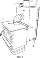
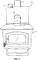
- the system 100 shown in Fig. 1 may be configured as a self-contained unit that may be retrofitted to a wood stove or other biomass furnace, represented by a fire box 102. Alternatively, a biomass furnace may be fabricated with an integrated pollution reduction system 100.
- the pollution control system 100 includes an active catalytic converter 104, multiple cyclonic separators, here represented by three cyclonic separators 106, 108 and 110, and multiple fabric filters (bag house filters), here represented by fabric filters 112 and 114.
- fabric filters 112 and 114 here represented by fabric filters 112 and 114.
- the system 100 is shown with three cyclonic separators 106, 108 and 110 and two fabric filters 112 and 114, other numbers of cyclonic separators and other numbers of fabric filters may be included.
- Fresh air is drawn into an air channel 144 from outside the pollution control system 100 and delivered to the catalytic converter 104 to provide additional oxygen to promote catalytic action.
- Various components of the pollution control system 100 such as for example the second and third cyclonic separators 108 and 110, may radiate or conduct heat toward the air channel 144.
- at least a portion of the air channel 144 may be disposed within the exhaust gas path.
- at least a portion of the air channel 144 includes a heat exchanger 146 thermally coupled to the exhaust gas path to extract heat from the exhaust gas. The air channel 144 therefore delivers air from outside the pollution control system 100, heated by the heat exchanger 146, to the catalytic converter 104.
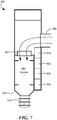
- Fresh air is admitted by two air channels 624 and 626 from outside the pollution reduction system 200. Warm steel that defines the air channels 624 and 626 heats the air.
- the fresh air then passes through heat exchangers 628 and 630, which are heated by exhaust gas exiting the second and third cyclonic separators 616 and 618, respectively, and possibly by conduction or radiation of heat from the cyclonic separators 604, 616 and 618 and radiation or conduction of heat from the catalyst 602.
- the heat exchangers 628 and 630 further warm the air, and then the warmed air enters the catalytic converter chamber 600 to provide oxygen for the catalyst 602.
- the memory may be random access memory (RAM), read-only memory (ROM), flash memory or any other memory, or combination thereof, suitable for storing control software or other instructions and data.
- Instructions defining the functions of the present invention may be delivered to a processor in many forms, including, but not limited to, information permanently stored on tangible non-writable storage media (e.g., read-only memory devices within a computer, such as ROM, or devices readable by a computer I/O attachment, such as CD-ROM or DVD disks), information alterably stored on tangible writable storage media (e.g., floppy disks, removable flash memory and hard drives) or information conveyed to a computer through a communication medium, including wired or wireless computer networks.
- tangible non-writable storage media e.g., read-only memory devices within a computer, such as ROM, or devices readable by a computer I/O attachment, such as CD-ROM or DVD disks
- information alterably stored on tangible writable storage media e.
Landscapes
- Engineering & Computer Science (AREA)
- Environmental & Geological Engineering (AREA)
- Chemical & Material Sciences (AREA)
- Health & Medical Sciences (AREA)
- Biomedical Technology (AREA)
- Analytical Chemistry (AREA)
- General Chemical & Material Sciences (AREA)
- Oil, Petroleum & Natural Gas (AREA)
- Chemical Kinetics & Catalysis (AREA)
- Chimneys And Flues (AREA)
Claims (10)
- Ein Luftverschmutzungskontrollsystem zur Kopplung an eine Abgas-Auslassöffnung einer Biomasseheizung, wobei das System umfasst:eine Abgas-Einlassöffnung (125, 206);einen katalytischen Wandler (116, 602), der kommunikativ mit der Abgas-Einlassöffnung (125, 206) gekoppelt ist;ein elektrisches Heizgerät(118), der in der Nähe des katalytischen Wandler (116, 602) angeordnet ist;einen Temperatursensor (122, 607), der in der Nähe des katalytischen Wandlers (116, 602) angeordnet ist;einen Regler (120), der mit dem Temperatursensor (122, 607) gekoppelt ist und von diesem ein Signal empfängt, das eine Temperatur in der Nähe des katalytischen Wandlers (116, 602) anzeigt, wobei der Regler (120) automatisch ein Signal erzeugt, das den Betrieb des elektrischen Heizgeräts (118) bewirkt, wenn die Temperatur in der Nähe des katalytischen Wandlers (116, 602) niedriger als ein vorbestimmter Wert ist;dadurch gekennzeichnet, dass es umfasst:einen ersten Zyklonabscheider (106, 604), der kommunikativ mit einem Ausgang des katalytischen Wandlers (116, 602) gekoppelt ist;einen zweiten Zyklonabscheider (108, 616);einen ersten Gewebefilter (112, 606), der kommunikativ zwischen einem Ausgang (130) des ersten Zyklonabscheiders (106, 604) und einem Eingang des zweiten Zyklonabscheiders (108, 616) gekoppelt ist;eine Abgas-Auslassöffnung (138, 210), die kommunikativ mit einem Ausgang des zweiten Zyklonabscheiders (108, 616) gekoppelt ist; undeinen motorgetriebenen Ventilator (142, 620), der kommunikativ zwischen einem Ausgang des zweiten Zyklonabscheiders (108, 616) und der Abgas-Auslassöffnung (138, 210) gekoppelt ist und bewirkt, dass das Abgas sequentiell von der Abgas-Einlassöffnung (125, 306) durch den katalytischen Wandler (116, 602), den ersten Zyklonabscheider (106, 604), den ersten Gewebefilter (112, 606), den zweiten Zyklonabscheider (108, 616) und die Abgas-Auslassöffnung (138, 210) strömt, in dieser Reihenfolge, wodurch ein Abgaspfad definiert wird.
- Ein Luftverschmutzungskontrollsystem nach Anspruch 1, ferner umfassend:mindestens eines von: (a) einem Drucksensor (143), der innerhalb des Abgaspfades angeordnet ist, und (b) einem Strömungsratensensor (143), der innerhalb des Abgaspfades angeordnet ist; undder Regler (120), das mit dem mindestens einen Drucksensor (143) und/oder Strömungsratensensor (143) gekoppelt ist und ein erstes Signal davon empfängt, wobei der Regler (120) automatisch ein zweites Signal erzeugt, das die Geschwindigkeit des motorgetriebenen Ventilators (142, 620) steuert, zumindest teilweise basierend auf dem ersten Signal.
- Ein Luftverschmutzungskontrollsystem nach Anspruch 1, das weiterhin einen Luftkanal (144, 624, 626) umfasst, der kommunikativ zwischen einer äußeren Umgebung des Luftverschmutzungskontrollsystems (100, 200) und dem katalytischen Wandler (116, 602) gekoppelt ist, wobei der Luftkanal (144, 624, 626) einen Wärmetauscher (146, 628, 630) umfasst, der thermisch mit dem Abgaspfad gekoppelt ist, wobei der Luftkanal (144, 624, 626) Luft von außerhalb des Luftverschmutzungskontrollsystems (100, 200) zu dem katalytischen Wandler (116, 602) liefert, die durch den Wärmetauscher (146, 628, 630) erwärmt wird,.
- Ein Luftverschmutzungskontrollsystem nach Anspruch 1, das weiterhin mindestens einen Wärmemasse-Stein (124, 632) in der Nähe des katalytischen Wandlers (116, 602) und des ersten Zyklonabscheiders (106, 604) umfasst, der thermisch mit diesen gekoppelt ist, wobei der mindestens eine Wärmemasse-Stein (124, 632) so positioniert ist, dass er Wärme von dem ersten Zyklonabscheider (106, 604) absorbiert, die Wärme speichert und zumindest (a) die gespeicherte Wärme in Richtung des katalytischen Wandlers (116, 602) abstrahlt und/ or (b) die gespeicherte Wärme in Richtung des katalytischen Wandlers (116, 602) leitet.
- Ein Luftverschmutzungskontrollsystem nach Anspruch 4, wobei der mindestens eine Wärmemasse-Stein (124, 632) mindestens drei Wärmemasse-Steine umfasst, die vertikal parallel zum ersten Zyklonabscheider (106, 604) gestapelt sind.
- Ein Luftverschmutzungskontrollsystem nach Anspruch 1, ferner umfassend:einen vom Benutzer entfernbaren Feinstaubbehälter (128, 614) mit einer Eingangsöffnung (612); undeine Wanne (610), der eine Ausgangsöffnung aufweist und einen Eingangsbereich definiert, wobei die Wanne (610) von dem Eingangsbereich zu der Ausgangsöffnung hin nach unten geneigt ist, einen Eingang des ersten Gewebefilters (606) und den Ausgang (130) des ersten Zyklonabscheiders (106, 604), die jeweils vertikal über mindestens einem jeweiligen Abschnitt des Eingangsbereichs ausgerichtet sind, wobei die Ausgangsöffnung der Wanne (610) mit der Eingangsöffnung (612) des Feinstaubbehälters (128, 614) verbunden ist.
- Luftverschmutzungskontrollsystem nach Anspruch 6, wobei der erste Zyklonabscheider (106, 604) im Wesentlichen parallel zum zweiten Zyklonabscheider (108, 616) ausgerichtet ist, das Abgas durch den ersten Zyklonabscheider (106, 604) nach unten und durch den zweiten Zyklonabscheider (108, 616) nach oben strömt, der Ausgang des ersten Gewebefilters (112, 606) unterhalb des Eingangs des zweiten Zyklonabscheiders (108) angeordnet und mit diesem kommunizierend gekoppelt ist, 616) der Ausgang (130) des ersten Zyklonabscheiders (106, 604) ist kommunizierend mit dem Boden des ersten Gewebefilters (112, 606) gekoppelt, so dass das Abgas nach unten aus dem Ausgang (130) des ersten Zyklonabscheiders (106, 604) und dann nach oben in den ersten Gewebefilter (112, 606) strömt, so dass sich das Abgas nach dem Verlassen des ersten Zyklonabscheiders (106, 604) um etwa 180 Grad dreht, um in den ersten Gewebefilter (112, 606) einzutreten.
- Ein Luftverschmutzungskontrollsystem nach Anspruch 1, ferner umfassend:einen dritten Zyklonabscheider (110, 618);einen zweiten Gewebefilter (114, 608), der kommunizierend zwischen dem Ausgang (130) des ersten Zyklonabscheiders (106, 604) und einem Eingang des dritten Zyklonabscheiders (110, 618) gekoppelt ist; wobei:die Abgas-Auslassöffnung (138, 210) kommunizierbar mit einem Ausgang des dritten Zyklonabscheiders (110, 618) sowie mit dem Ausgang des zweiten Zyklonabscheiders (108, 616) gekoppelt ist;mindestens ein Teil des Abgaspfades den zweiten Gewebefilter (114, 608) und den dritten Zyklonabscheider (110, 618) enthält; undder motorgetriebene Ventilator (124, 620) bewirkt, dass zumindest ein Teil des Abgases nacheinander durch den zweiten Gewebefilter (114, 608) und den dritten Zyklonabscheider (110, 618) in dieser Reihenfolge strömt.
- Ein Luftverschmutzungskontrollsystem nach Anspruch 8, ferner umfassend:einen vom Benutzer entfernbaren Feinstaubbehälter (128, 614) mit einer Eingangsöffnung (612); undeine Wanne (610), die einen Ausgangsanschluss aufweist und einen Eingangsbereich definiert, wobei die Wanne (610) von dem Eingangsbereich zu dem Ausgangsanschluss hin nach unten geneigt ist, einen Eingang des ersten Gewebefilters (112, 606), einen Eingang des zweiten Gewebefilters (114), 608) und den Ausgang (130) des ersten Zyklonabscheiders (106, 604), die jeweils vertikal über mindestens einem entsprechenden Teil des Eingangsbereichs ausgerichtet sind, wobei der Ausgangsanschluss der Wanne (610) mit dem Eingangsanschluss (612) des Feinstaubbehälters (128, 614) verbunden ist.
- Ein Luftverschmutzungskontrollsystem nach Anspruch 9, wobei der erste Zyklonabscheider (106, 604) im Wesentlichen parallel zum zweiten Zyklonabscheider (108, 616) ausgerichtet ist und im Wesentlichen parallel zum dritten Zyklonabscheider (110, 618), das Abgas nach unten durch den ersten Zyklonabscheider (106, 604) und nach oben durch den zweiten (108, 616) und dritten (110, 618) Zyklonabscheider strömt, der Ausgang des ersten Gewebefilters (112, 606) unterhalb des Eingangs des zweiten Zyklonabscheiders (108, 616) angeordnet und mit diesem kommunizierend gekoppelt ist, der Ausgang des zweiten Gewebefilters (114, 608) unterhalb des Eingangs des dritten Zyklonabscheiders (110, 618) angeordnet und mit diesem kommunizierend gekoppelt ist, der Ausgang (130) des ersten Zyklonabscheiders (106, 604) kommunizierend mit dem Boden des ersten (112, 606) und zweiten (114, 608) Gewebefilters gekoppelt ist, so dass das Abgas nach unten aus dem Ausgang (130) des ersten Zyklonabscheiders (106, 604) und dann nach oben in den ersten (112, 606) und zweiten (114, 608) Gewebefilter strömt, derart, dass mindestens ein Teil des Abgases sich nach dem Verlassen des ersten Zyklonabscheiders (106, 604) um etwa 180 Grad dreht, um in den ersten Gewebefilter (112, 606) einzutreten, und dass ein anderer zumindest Teil des Abgases sich nach dem Verlassen des ersten Zyklonabscheiders (106, 604) um etwa 180 Grad dreht, um in den zweiten Gewebefilter (114, 608) einzutreten.
Applications Claiming Priority (2)
| Application Number | Priority Date | Filing Date | Title |
|---|---|---|---|
| US201462065810P | 2014-10-20 | 2014-10-20 | |
| PCT/US2015/056182 WO2016064717A1 (en) | 2014-10-20 | 2015-10-19 | Combined catalytic converter and cyclonic separator for biofuel-fired furnace |
Publications (3)
| Publication Number | Publication Date |
|---|---|
| EP3209939A1 EP3209939A1 (de) | 2017-08-30 |
| EP3209939A4 EP3209939A4 (de) | 2017-12-27 |
| EP3209939B1 true EP3209939B1 (de) | 2020-07-29 |
Family
ID=55748273
Family Applications (1)
| Application Number | Title | Priority Date | Filing Date |
|---|---|---|---|
| EP15851933.0A Active EP3209939B1 (de) | 2014-10-20 | 2015-10-19 | Kombinierter katalysator und zyklonabscheider für einen mit biobrennstoff befeuerten ofen |
Country Status (4)
| Country | Link |
|---|---|
| US (1) | US9789440B2 (de) |
| EP (1) | EP3209939B1 (de) |
| PT (1) | PT3209939T (de) |
| WO (1) | WO2016064717A1 (de) |
Families Citing this family (4)
| Publication number | Priority date | Publication date | Assignee | Title |
|---|---|---|---|---|
| US11266937B2 (en) * | 2017-03-28 | 2022-03-08 | Hewlett-Packard Development Company, L.P. | Air flow rates in cyclonic particle separation chambers |
| DE102017218374A1 (de) | 2017-10-13 | 2019-04-18 | Continental Automotive Gmbh | Vorrichtung und Verfahren zum Ermitteln einer Heiztemperatur eines Heizelements für einen elektrisch beheizbaren Katalysator und Kraftfahrzeug |
| DE102020106773A1 (de) | 2020-03-12 | 2021-09-16 | Kutzner + Weber Gmbh | Vorrichtung zum Reinigen von Abgasen aus einer Feuerstelle |
| CN112902209B (zh) * | 2021-01-22 | 2024-03-26 | 徐州工业锅炉有限公司 | 一种生物质散料直燃装置 |
Family Cites Families (7)
| Publication number | Priority date | Publication date | Assignee | Title |
|---|---|---|---|---|
| US3895918A (en) * | 1973-01-16 | 1975-07-22 | James H Mueller | High efficiency, thermal regeneration anti-pollution system |
| US7007616B2 (en) * | 1998-08-21 | 2006-03-07 | Nathaniel Energy Corporation | Oxygen-based biomass combustion system and method |
| US20050201914A1 (en) * | 2004-03-12 | 2005-09-15 | American Electric Power Company, Inc. | System and method for treating a flue gas stream |
| FR2895413B1 (fr) * | 2005-12-27 | 2011-07-29 | Alstom Technology Ltd | Installation de conversion d'hydrocarbures petroliers a installation de combustion integree comprenant une capture du dioxyde de carbone |
| EP2015859A4 (de) | 2006-05-05 | 2010-09-29 | Plascoenergy Ip Holdings Slb | Gasklimatisierungssystem |
| FR2928846B1 (fr) * | 2008-03-20 | 2010-10-22 | Fondis Sa | Dispositif d'epuration a catalyseur des gaz et fumees de combustion d'un appareil de chauffage a combustible solide. |
| US8812162B2 (en) | 2010-11-05 | 2014-08-19 | Clearstak Llc | Intelligently-controlled catalytic converter for biofuel-fired boiler |
-
2015
- 2015-10-19 WO PCT/US2015/056182 patent/WO2016064717A1/en not_active Ceased
- 2015-10-19 EP EP15851933.0A patent/EP3209939B1/de active Active
- 2015-10-19 US US14/886,516 patent/US9789440B2/en active Active
- 2015-10-19 PT PT158519330T patent/PT3209939T/pt unknown
Non-Patent Citations (1)
| Title |
|---|
| None * |
Also Published As
| Publication number | Publication date |
|---|---|
| US20160107120A1 (en) | 2016-04-21 |
| US9789440B2 (en) | 2017-10-17 |
| WO2016064717A1 (en) | 2016-04-28 |
| PT3209939T (pt) | 2020-09-01 |
| EP3209939A4 (de) | 2017-12-27 |
| EP3209939A1 (de) | 2017-08-30 |
Similar Documents
| Publication | Publication Date | Title |
|---|---|---|
| US20200158339A1 (en) | Intelligent Temperature Controller for Biofuel-Fired Burner | |
| US9789440B2 (en) | Combined catalytic converter and cyclonic separator for biofuel-fired furnace | |
| US7866311B2 (en) | High speed solid cooking fuel igniter | |
| ES2953497T3 (es) | Aparatos asistidos por catalizador que no se pueden desviar | |
| CN109564028A (zh) | 烟道气处理系统和方法 | |
| CA2823428A1 (en) | A boiler | |
| CN202532448U (zh) | 固体燃料锅炉 | |
| EP3775690A1 (de) | Verfahren zur bereitstellung von sauberer wohnraumkomfortbeheizung | |
| US20150253006A1 (en) | Emission reduction device for a wood heater | |
| CN101319792A (zh) | 多功能煤气灶具装置 | |
| JP2006234302A (ja) | 木質ペレット燃焼装置 | |
| TW202037846A (zh) | 蒸汽熱水鍋爐 | |
| JP2010255971A (ja) | バイオマス燃焼装置 | |
| CN201803378U (zh) | 一种多功能炉灶 | |
| KR20230162308A (ko) | 연소가스 정화장치를 구비한 화목보일러 | |
| CN201050813Y (zh) | 多功能煤气灶具装置 | |
| CN201488009U (zh) | 节能环保供暖炊事多用炉 | |
| JP3127645U (ja) | 有機廃棄物処理炉 | |
| KR200238406Y1 (ko) | 연탄 열풍보일러 | |
| CN103528096B (zh) | 焚烧炉 | |
| RU2451876C1 (ru) | Способ регулирования мощности теплогенератора с псевдоожиженным слоем | |
| US20120125241A1 (en) | Waste Oil Furnace | |
| RU121041U1 (ru) | Котел отопительный | |
| CN201083397Y (zh) | 节能热管煤转气锅炉 | |
| KR20240178154A (ko) | 에너지 절감 및 대기오염원 저감을 위한 엘피지 폐용기 활용 취사겸용 보일러 |
Legal Events
| Date | Code | Title | Description |
|---|---|---|---|
| STAA | Information on the status of an ep patent application or granted ep patent |
Free format text: STATUS: THE INTERNATIONAL PUBLICATION HAS BEEN MADE |
|
| PUAI | Public reference made under article 153(3) epc to a published international application that has entered the european phase |
Free format text: ORIGINAL CODE: 0009012 |
|
| STAA | Information on the status of an ep patent application or granted ep patent |
Free format text: STATUS: REQUEST FOR EXAMINATION WAS MADE |
|
| 17P | Request for examination filed |
Effective date: 20170324 |
|
| AK | Designated contracting states |
Kind code of ref document: A1 Designated state(s): AL AT BE BG CH CY CZ DE DK EE ES FI FR GB GR HR HU IE IS IT LI LT LU LV MC MK MT NL NO PL PT RO RS SE SI SK SM TR |
|
| AX | Request for extension of the european patent |
Extension state: BA ME |
|
| A4 | Supplementary search report drawn up and despatched |
Effective date: 20171123 |
|
| RIC1 | Information provided on ipc code assigned before grant |
Ipc: F23J 15/02 20060101ALI20171117BHEP Ipc: B01D 53/86 20060101AFI20171117BHEP Ipc: F23J 15/00 20060101ALI20171117BHEP |
|
| DAV | Request for validation of the european patent (deleted) | ||
| DAX | Request for extension of the european patent (deleted) | ||
| REG | Reference to a national code |
Ref country code: DE Ref legal event code: R079 Ref document number: 602015056664 Country of ref document: DE Free format text: PREVIOUS MAIN CLASS: F23J0015000000 Ipc: B01D0053860000 |
|
| GRAP | Despatch of communication of intention to grant a patent |
Free format text: ORIGINAL CODE: EPIDOSNIGR1 |
|
| STAA | Information on the status of an ep patent application or granted ep patent |
Free format text: STATUS: GRANT OF PATENT IS INTENDED |
|
| RIC1 | Information provided on ipc code assigned before grant |
Ipc: F23J 15/02 20060101ALI20200331BHEP Ipc: F23J 15/00 20060101ALI20200331BHEP Ipc: B01D 53/86 20060101AFI20200331BHEP |
|
| INTG | Intention to grant announced |
Effective date: 20200422 |
|
| GRAS | Grant fee paid |
Free format text: ORIGINAL CODE: EPIDOSNIGR3 |
|
| GRAA | (expected) grant |
Free format text: ORIGINAL CODE: 0009210 |
|
| STAA | Information on the status of an ep patent application or granted ep patent |
Free format text: STATUS: THE PATENT HAS BEEN GRANTED |
|
| AK | Designated contracting states |
Kind code of ref document: B1 Designated state(s): AL AT BE BG CH CY CZ DE DK EE ES FI FR GB GR HR HU IE IS IT LI LT LU LV MC MK MT NL NO PL PT RO RS SE SI SK SM TR |
|
| REG | Reference to a national code |
Ref country code: CH Ref legal event code: EP |
|
| REG | Reference to a national code |
Ref country code: AT Ref legal event code: REF Ref document number: 1295128 Country of ref document: AT Kind code of ref document: T Effective date: 20200815 |
|
| REG | Reference to a national code |
Ref country code: IE Ref legal event code: FG4D |
|
| REG | Reference to a national code |
Ref country code: DE Ref legal event code: R096 Ref document number: 602015056664 Country of ref document: DE |
|
| REG | Reference to a national code |
Ref country code: PT Ref legal event code: SC4A Ref document number: 3209939 Country of ref document: PT Date of ref document: 20200901 Kind code of ref document: T Free format text: AVAILABILITY OF NATIONAL TRANSLATION Effective date: 20200825 |
|
| REG | Reference to a national code |
Ref country code: LT Ref legal event code: MG4D |
|
| REG | Reference to a national code |
Ref country code: NL Ref legal event code: MP Effective date: 20200729 |
|
| REG | Reference to a national code |
Ref country code: AT Ref legal event code: MK05 Ref document number: 1295128 Country of ref document: AT Kind code of ref document: T Effective date: 20200729 |
|
| PG25 | Lapsed in a contracting state [announced via postgrant information from national office to epo] |
Ref country code: ES Free format text: LAPSE BECAUSE OF FAILURE TO SUBMIT A TRANSLATION OF THE DESCRIPTION OR TO PAY THE FEE WITHIN THE PRESCRIBED TIME-LIMIT Effective date: 20200729 Ref country code: GR Free format text: LAPSE BECAUSE OF FAILURE TO SUBMIT A TRANSLATION OF THE DESCRIPTION OR TO PAY THE FEE WITHIN THE PRESCRIBED TIME-LIMIT Effective date: 20201030 Ref country code: BG Free format text: LAPSE BECAUSE OF FAILURE TO SUBMIT A TRANSLATION OF THE DESCRIPTION OR TO PAY THE FEE WITHIN THE PRESCRIBED TIME-LIMIT Effective date: 20201029 Ref country code: AT Free format text: LAPSE BECAUSE OF FAILURE TO SUBMIT A TRANSLATION OF THE DESCRIPTION OR TO PAY THE FEE WITHIN THE PRESCRIBED TIME-LIMIT Effective date: 20200729 Ref country code: HR Free format text: LAPSE BECAUSE OF FAILURE TO SUBMIT A TRANSLATION OF THE DESCRIPTION OR TO PAY THE FEE WITHIN THE PRESCRIBED TIME-LIMIT Effective date: 20200729 Ref country code: LT Free format text: LAPSE BECAUSE OF FAILURE TO SUBMIT A TRANSLATION OF THE DESCRIPTION OR TO PAY THE FEE WITHIN THE PRESCRIBED TIME-LIMIT Effective date: 20200729 Ref country code: NO Free format text: LAPSE BECAUSE OF FAILURE TO SUBMIT A TRANSLATION OF THE DESCRIPTION OR TO PAY THE FEE WITHIN THE PRESCRIBED TIME-LIMIT Effective date: 20201029 Ref country code: FI Free format text: LAPSE BECAUSE OF FAILURE TO SUBMIT A TRANSLATION OF THE DESCRIPTION OR TO PAY THE FEE WITHIN THE PRESCRIBED TIME-LIMIT Effective date: 20200729 Ref country code: SE Free format text: LAPSE BECAUSE OF FAILURE TO SUBMIT A TRANSLATION OF THE DESCRIPTION OR TO PAY THE FEE WITHIN THE PRESCRIBED TIME-LIMIT Effective date: 20200729 |
|
| PG25 | Lapsed in a contracting state [announced via postgrant information from national office to epo] |
Ref country code: RS Free format text: LAPSE BECAUSE OF FAILURE TO SUBMIT A TRANSLATION OF THE DESCRIPTION OR TO PAY THE FEE WITHIN THE PRESCRIBED TIME-LIMIT Effective date: 20200729 Ref country code: LV Free format text: LAPSE BECAUSE OF FAILURE TO SUBMIT A TRANSLATION OF THE DESCRIPTION OR TO PAY THE FEE WITHIN THE PRESCRIBED TIME-LIMIT Effective date: 20200729 Ref country code: PL Free format text: LAPSE BECAUSE OF FAILURE TO SUBMIT A TRANSLATION OF THE DESCRIPTION OR TO PAY THE FEE WITHIN THE PRESCRIBED TIME-LIMIT Effective date: 20200729 Ref country code: IS Free format text: LAPSE BECAUSE OF FAILURE TO SUBMIT A TRANSLATION OF THE DESCRIPTION OR TO PAY THE FEE WITHIN THE PRESCRIBED TIME-LIMIT Effective date: 20201129 |
|
| PG25 | Lapsed in a contracting state [announced via postgrant information from national office to epo] |
Ref country code: NL Free format text: LAPSE BECAUSE OF FAILURE TO SUBMIT A TRANSLATION OF THE DESCRIPTION OR TO PAY THE FEE WITHIN THE PRESCRIBED TIME-LIMIT Effective date: 20200729 |
|
| PG25 | Lapsed in a contracting state [announced via postgrant information from national office to epo] |
Ref country code: SM Free format text: LAPSE BECAUSE OF FAILURE TO SUBMIT A TRANSLATION OF THE DESCRIPTION OR TO PAY THE FEE WITHIN THE PRESCRIBED TIME-LIMIT Effective date: 20200729 Ref country code: RO Free format text: LAPSE BECAUSE OF FAILURE TO SUBMIT A TRANSLATION OF THE DESCRIPTION OR TO PAY THE FEE WITHIN THE PRESCRIBED TIME-LIMIT Effective date: 20200729 Ref country code: EE Free format text: LAPSE BECAUSE OF FAILURE TO SUBMIT A TRANSLATION OF THE DESCRIPTION OR TO PAY THE FEE WITHIN THE PRESCRIBED TIME-LIMIT Effective date: 20200729 Ref country code: IT Free format text: LAPSE BECAUSE OF FAILURE TO SUBMIT A TRANSLATION OF THE DESCRIPTION OR TO PAY THE FEE WITHIN THE PRESCRIBED TIME-LIMIT Effective date: 20200729 Ref country code: CZ Free format text: LAPSE BECAUSE OF FAILURE TO SUBMIT A TRANSLATION OF THE DESCRIPTION OR TO PAY THE FEE WITHIN THE PRESCRIBED TIME-LIMIT Effective date: 20200729 Ref country code: DK Free format text: LAPSE BECAUSE OF FAILURE TO SUBMIT A TRANSLATION OF THE DESCRIPTION OR TO PAY THE FEE WITHIN THE PRESCRIBED TIME-LIMIT Effective date: 20200729 |
|
| REG | Reference to a national code |
Ref country code: DE Ref legal event code: R097 Ref document number: 602015056664 Country of ref document: DE |
|
| REG | Reference to a national code |
Ref country code: DE Ref legal event code: R119 Ref document number: 602015056664 Country of ref document: DE |
|
| PG25 | Lapsed in a contracting state [announced via postgrant information from national office to epo] |
Ref country code: AL Free format text: LAPSE BECAUSE OF FAILURE TO SUBMIT A TRANSLATION OF THE DESCRIPTION OR TO PAY THE FEE WITHIN THE PRESCRIBED TIME-LIMIT Effective date: 20200729 |
|
| REG | Reference to a national code |
Ref country code: CH Ref legal event code: PL |
|
| PLBE | No opposition filed within time limit |
Free format text: ORIGINAL CODE: 0009261 |
|
| STAA | Information on the status of an ep patent application or granted ep patent |
Free format text: STATUS: NO OPPOSITION FILED WITHIN TIME LIMIT |
|
| GBPC | Gb: european patent ceased through non-payment of renewal fee |
Effective date: 20201029 |
|
| PG25 | Lapsed in a contracting state [announced via postgrant information from national office to epo] |
Ref country code: LU Free format text: LAPSE BECAUSE OF NON-PAYMENT OF DUE FEES Effective date: 20201019 Ref country code: SK Free format text: LAPSE BECAUSE OF FAILURE TO SUBMIT A TRANSLATION OF THE DESCRIPTION OR TO PAY THE FEE WITHIN THE PRESCRIBED TIME-LIMIT Effective date: 20200729 Ref country code: MC Free format text: LAPSE BECAUSE OF FAILURE TO SUBMIT A TRANSLATION OF THE DESCRIPTION OR TO PAY THE FEE WITHIN THE PRESCRIBED TIME-LIMIT Effective date: 20200729 |
|
| 26N | No opposition filed |
Effective date: 20210430 |
|
| REG | Reference to a national code |
Ref country code: BE Ref legal event code: MM Effective date: 20201031 |
|
| PG25 | Lapsed in a contracting state [announced via postgrant information from national office to epo] |
Ref country code: DE Free format text: LAPSE BECAUSE OF NON-PAYMENT OF DUE FEES Effective date: 20210501 Ref country code: FR Free format text: LAPSE BECAUSE OF NON-PAYMENT OF DUE FEES Effective date: 20201031 |
|
| PG25 | Lapsed in a contracting state [announced via postgrant information from national office to epo] |
Ref country code: SI Free format text: LAPSE BECAUSE OF FAILURE TO SUBMIT A TRANSLATION OF THE DESCRIPTION OR TO PAY THE FEE WITHIN THE PRESCRIBED TIME-LIMIT Effective date: 20200729 Ref country code: LI Free format text: LAPSE BECAUSE OF NON-PAYMENT OF DUE FEES Effective date: 20201031 Ref country code: GB Free format text: LAPSE BECAUSE OF NON-PAYMENT OF DUE FEES Effective date: 20201029 Ref country code: CH Free format text: LAPSE BECAUSE OF NON-PAYMENT OF DUE FEES Effective date: 20201031 Ref country code: BE Free format text: LAPSE BECAUSE OF NON-PAYMENT OF DUE FEES Effective date: 20201031 |
|
| PG25 | Lapsed in a contracting state [announced via postgrant information from national office to epo] |
Ref country code: IE Free format text: LAPSE BECAUSE OF NON-PAYMENT OF DUE FEES Effective date: 20201019 |
|
| PG25 | Lapsed in a contracting state [announced via postgrant information from national office to epo] |
Ref country code: PT Free format text: LAPSE BECAUSE OF NON-PAYMENT OF DUE FEES Effective date: 20210719 |
|
| PG25 | Lapsed in a contracting state [announced via postgrant information from national office to epo] |
Ref country code: TR Free format text: LAPSE BECAUSE OF FAILURE TO SUBMIT A TRANSLATION OF THE DESCRIPTION OR TO PAY THE FEE WITHIN THE PRESCRIBED TIME-LIMIT Effective date: 20200729 Ref country code: MT Free format text: LAPSE BECAUSE OF FAILURE TO SUBMIT A TRANSLATION OF THE DESCRIPTION OR TO PAY THE FEE WITHIN THE PRESCRIBED TIME-LIMIT Effective date: 20200729 Ref country code: CY Free format text: LAPSE BECAUSE OF FAILURE TO SUBMIT A TRANSLATION OF THE DESCRIPTION OR TO PAY THE FEE WITHIN THE PRESCRIBED TIME-LIMIT Effective date: 20200729 |
|
| PG25 | Lapsed in a contracting state [announced via postgrant information from national office to epo] |
Ref country code: MK Free format text: LAPSE BECAUSE OF FAILURE TO SUBMIT A TRANSLATION OF THE DESCRIPTION OR TO PAY THE FEE WITHIN THE PRESCRIBED TIME-LIMIT Effective date: 20200729 |