EP3209848B1 - Procédé et appareil de forage d'essai simulant le mouvement dynamique de la mer basé à terre - Google Patents
Procédé et appareil de forage d'essai simulant le mouvement dynamique de la mer basé à terre Download PDFInfo
- Publication number
- EP3209848B1 EP3209848B1 EP15813602.8A EP15813602A EP3209848B1 EP 3209848 B1 EP3209848 B1 EP 3209848B1 EP 15813602 A EP15813602 A EP 15813602A EP 3209848 B1 EP3209848 B1 EP 3209848B1
- Authority
- EP
- European Patent Office
- Prior art keywords
- drilling
- motion
- tubulars
- tower
- rig
- Prior art date
- Legal status (The legal status is an assumption and is not a legal conclusion. Google has not performed a legal analysis and makes no representation as to the accuracy of the status listed.)
- Active
Links
- 230000033001 locomotion Effects 0.000 title claims description 204
- 238000005553 drilling Methods 0.000 title claims description 200
- 238000012360 testing method Methods 0.000 title claims description 40
- 238000000034 method Methods 0.000 title claims description 8
- 238000003860 storage Methods 0.000 claims description 91
- 238000010304 firing Methods 0.000 claims description 59
- 150000001875 compounds Chemical class 0.000 claims description 56
- 125000004122 cyclic group Chemical group 0.000 claims description 39
- 239000002689 soil Substances 0.000 claims description 14
- 229910000831 Steel Inorganic materials 0.000 claims description 5
- 239000010959 steel Substances 0.000 claims description 5
- 230000001133 acceleration Effects 0.000 claims description 4
- XLYOFNOQVPJJNP-UHFFFAOYSA-N water Substances O XLYOFNOQVPJJNP-UHFFFAOYSA-N 0.000 claims description 4
- 239000002184 metal Substances 0.000 description 15
- 229910052751 metal Inorganic materials 0.000 description 15
- XEEYBQQBJWHFJM-UHFFFAOYSA-N Iron Chemical compound [Fe] XEEYBQQBJWHFJM-UHFFFAOYSA-N 0.000 description 12
- 230000000712 assembly Effects 0.000 description 7
- 238000000429 assembly Methods 0.000 description 7
- 239000004567 concrete Substances 0.000 description 6
- 229910052742 iron Inorganic materials 0.000 description 6
- 238000011161 development Methods 0.000 description 4
- 230000000694 effects Effects 0.000 description 4
- 230000014759 maintenance of location Effects 0.000 description 4
- 238000005259 measurement Methods 0.000 description 4
- 238000013461 design Methods 0.000 description 3
- 230000003993 interaction Effects 0.000 description 2
- 230000002035 prolonged effect Effects 0.000 description 2
- 239000011150 reinforced concrete Substances 0.000 description 2
- 238000004088 simulation Methods 0.000 description 2
- 230000003068 static effect Effects 0.000 description 2
- 239000000758 substrate Substances 0.000 description 2
- 239000000725 suspension Substances 0.000 description 2
- 206010065042 Immune reconstitution inflammatory syndrome Diseases 0.000 description 1
- 238000004590 computer program Methods 0.000 description 1
- 230000001351 cycling effect Effects 0.000 description 1
- 238000013016 damping Methods 0.000 description 1
- 230000001419 dependent effect Effects 0.000 description 1
- 238000012938 design process Methods 0.000 description 1
- 230000009189 diving Effects 0.000 description 1
- 239000012530 fluid Substances 0.000 description 1
- 230000005484 gravity Effects 0.000 description 1
- 238000009434 installation Methods 0.000 description 1
- 238000005381 potential energy Methods 0.000 description 1
- 101150006257 rig-4 gene Proteins 0.000 description 1
- 239000004576 sand Substances 0.000 description 1
- 238000009864 tensile test Methods 0.000 description 1
Images


Classifications
-
- G—PHYSICS
- G01—MEASURING; TESTING
- G01M—TESTING STATIC OR DYNAMIC BALANCE OF MACHINES OR STRUCTURES; TESTING OF STRUCTURES OR APPARATUS, NOT OTHERWISE PROVIDED FOR
- G01M99/00—Subject matter not provided for in other groups of this subclass
- G01M99/007—Subject matter not provided for in other groups of this subclass by applying a load, e.g. for resistance or wear testing
-
- E—FIXED CONSTRUCTIONS
- E21—EARTH DRILLING; MINING
- E21B—EARTH DRILLING, e.g. DEEP DRILLING; OBTAINING OIL, GAS, WATER, SOLUBLE OR MELTABLE MATERIALS OR A SLURRY OF MINERALS FROM WELLS
- E21B15/00—Supports for the drilling machine, e.g. derricks or masts
- E21B15/006—Means for anchoring the drilling machine to the ground
-
- E—FIXED CONSTRUCTIONS
- E21—EARTH DRILLING; MINING
- E21B—EARTH DRILLING, e.g. DEEP DRILLING; OBTAINING OIL, GAS, WATER, SOLUBLE OR MELTABLE MATERIALS OR A SLURRY OF MINERALS FROM WELLS
- E21B15/00—Supports for the drilling machine, e.g. derricks or masts
- E21B15/02—Supports for the drilling machine, e.g. derricks or masts specially adapted for underwater drilling
-
- E—FIXED CONSTRUCTIONS
- E21—EARTH DRILLING; MINING
- E21B—EARTH DRILLING, e.g. DEEP DRILLING; OBTAINING OIL, GAS, WATER, SOLUBLE OR MELTABLE MATERIALS OR A SLURRY OF MINERALS FROM WELLS
- E21B15/00—Supports for the drilling machine, e.g. derricks or masts
- E21B15/04—Supports for the drilling machine, e.g. derricks or masts specially adapted for directional drilling, e.g. slant hole rigs
-
- E—FIXED CONSTRUCTIONS
- E21—EARTH DRILLING; MINING
- E21B—EARTH DRILLING, e.g. DEEP DRILLING; OBTAINING OIL, GAS, WATER, SOLUBLE OR MELTABLE MATERIALS OR A SLURRY OF MINERALS FROM WELLS
- E21B19/00—Handling rods, casings, tubes or the like outside the borehole, e.g. in the derrick; Apparatus for feeding the rods or cables
- E21B19/14—Racks, ramps, troughs or bins, for holding the lengths of rod singly or connected; Handling between storage place and borehole
- E21B19/143—Racks, ramps, troughs or bins, for holding the lengths of rod singly or connected; Handling between storage place and borehole specially adapted for underwater drilling
-
- E—FIXED CONSTRUCTIONS
- E21—EARTH DRILLING; MINING
- E21B—EARTH DRILLING, e.g. DEEP DRILLING; OBTAINING OIL, GAS, WATER, SOLUBLE OR MELTABLE MATERIALS OR A SLURRY OF MINERALS FROM WELLS
- E21B7/00—Special methods or apparatus for drilling
- E21B7/12—Underwater drilling
- E21B7/128—Underwater drilling from floating support with independent underwater anchored guide base
Definitions
- the present invention relates to the field of drilling rigs, in particular to the development of offshore drilling rigs of the type that is to be installed on a floating offshore drilling vessel and as such subjected to sea state induced motions.
- the drilling rig and all its components are subjected to sea state induced motions, e.g. to roll motion.
- the height of the drilling rig can be very substantial, e.g. more than 50 meters, e.g. in view of handling, including storing, multiple joint tubular stands, e.g. triples or quads or even longer stands, e.g. stands having a length exceeding 30.5 m (100 foot).
- the present invention aims to facilitate and enhance the further development of drilling rigs that are to be installed on floating offshore drilling vessels.
- the present invention achieves this aim by providing a land based dynamic sea motion simulating test drilling rig comprising:
- each of the drilling tubulars storage and tubulars racker device may be directly secured to the motion base, but it is also envisaged, as shown in the drawings, that e.g. the racker device is connected to the tower and thereby indirectly to the motion base. Yet, even when connected indirectly, these components are subjected to the pivoting or swaying motion when the motion drive is in operation.
- the development of this type of rigs to be installed on a floating offshore vessel can be enhanced as components and/or their interaction and/or accuracy of motion performed can be monitored during a test, e.g. simulating the making up and/or breaking up of a tubulars string in the firing line, whilst under simulated sea motion conditions.
- the long-time behaviour, e.g. in view of wear, of one or more components of the drilling rig can be monitored and design changes proposed or the design accepted.
- the tubular racker device can be tested under sea motion conditions as to the accuracy of the motion of the tubular racker device when simultaneously subjected to said simulated pivoting motion.
- one can monitor the accuracy of the motions performed by the racker device, e.g. allowing to optimize a computer program governing such motion and/or interaction with or design of one or more sensors involved in controlling motion of the racker device.
- the tower height may in embodiments be greater than 50 meters.
- the tower and the hoisting device thereof, the tubulars storage, and the tubulars racker are adapted to handle tubular stands having a length greater than 27m (90 feet), e.g. 36.6 m (120 feet) drill pipe stands.
- a deep well sunken into the soil at a location aligned with the firing line.
- a concrete lined well e.g. of stacked rings or otherwise, or a steel walled well is provided. It is preferred for said well to have a diameter greater than said drilling tubulars, in particular such a diameter that a drilling tubular section extending into said well is able to move within the well as a result of the pivotal motion imparted to the assembly by the motion drive.
- the diameter of the well is between 1 and 10 meters, e.g. 3 meters.
- the well has a depth of at least 30 meters, e.g. of about 50 meters, e.g. of about 100 meters.
- the well may be entirely empty so that the string is freely suspended in the well.
- One may also envisage, e.g. for simulating underwater conditions or to practice diving operations or operations with remote operated vehicles, that the well is - e.g. in part - filled with a fluid, e.g. with water.
- the well is equipped with a pump device to pump out water if desired.
- the well can comprise a bottom, e.g. a steel or reinforced concrete bottom, which bottom is provided with one or more premade drilling holes through which a borehole can be drilled deeper into the soil below the well. Such boreholes can subsequently be filled again to permit repeated drilling tests.
- the holes permit the simulation of drilling activities, e.g. through a drilling riser, possibly arranged within the well, and/or into the soil, the simulation of the standbuilding and tripping of a drill string, etc.
- the depth of the drilling holes below the well can be between 100 and 800 m, e.g. 400 m.
- the bottom of the well may comprise attachment means, e.g. a hook or eye plate, e.g. having a tensile load capacity of at least 50 tonnes, e.g. to attach one or more cables in order to perform tests on the hoisting device of the drilling tower.
- attachment means e.g. a hook or eye plate, e.g. having a tensile load capacity of at least 50 tonnes, e.g. to attach one or more cables in order to perform tests on the hoisting device of the drilling tower.
- the motion drive is adapted to impart a cyclic pivoting motion having a period that lies in a range between 2 and 30 seconds.
- the motion drive is a variable drive, e.g. adapted to impart any period over a range between 2 and 30 seconds.
- the motion drive is adapted to impart a cyclic pivoting motion having a pivot angle relative to vertical of at least 1°, e.g. of at most +/- 10°.
- the motion drive is adapted to impart a variable pivot angle in a range greater than +/-1°, e.g. between +/- 1 ° and +/- 5°.
- tests are performed with a cyclic pivoting of about +/- 2° and a period of between 4 and 12 seconds.
- the pivot structure provides a single horizontal pivot axis, preferably intersecting the firing line.
- the motion drive comprises a strut having an upper end attached to the drilling tower at an elevated position thereof and having a lower end attached to a drive motor device.
- the drive motor device comprises a motor driven rocker arm pivotally connected to said strut and adapted to perform a cyclic rocking motion about a horizontal rocker arm axis.
- the motion drive may be a drive means comprising e.g. the abovementioned motor driven rocker arm, a hydraulic cylinder, a flywheel or a crankshaft.
- drive means require large amounts of power, for example around 1 Megawatt, in order to impart a cyclic pivot motion to the assembly of drilling tower, drilling tubulars storage and tubulars racker device.
- the large power consumption of these drive means forms an impediment to the establishment of the test drilling rig.
- the cyclic motion is imparted to said assembly in a way that consumes much less power by providing a pendulum system comprising:
- the pendulum system does allow for a much smaller drive motor using less energy.
- the cyclic motion of the assembly of compound pendulum, strut, motion base, drilling tower, drilling tubulars storage and tubulars racker device can be driven with a relatively low power consumption, as during cyclic motion at the resonance frequency of said assembly energy is efficiently transferred from kinetic energy to potential energy and vice versa.
- the structure of the pendulum system may be rather large, e.g. for a total mass of the drilling tower, motion base, drilling tubulars storage loaded with drilling tubulars, and racker devices in the range between 1000 - 1500 metric tonnes the compound pendulum may weigh e.g. in the region of 150- 350 metric tonnes. Yet it is envisaged that such a system may be powered by a drive motor having a capacity in the range between 30 and 100 kW, e.g. about 40 kW.
- the pivot connector that connects the strut to the compound pendulum is offset from said swing axis between compound pendulum and frame so that a rotation of the compound pendulum about its said at least one horizontal swing axis results in a motion of the strut and, vice versa, a motion of the strut leads to a rotation of the compound pendulum about its said at least one horizontal swing axis.
- the drive motor imparts a small non-zero pivot angle to said assembly to start the cyclic motion and during subsequent swings supplies additional energy to impart a cyclic motion with a larger maximal non-zero pivot angle of the motion base relative to horizontal.
- the pendulum system can further comprise one or more weight elements that can be added to or removed from the compound pendulum.
- the total weigh variation of the compound pendulum by means of these weight elements can be at least 50 tonnes, e.g. more than 100 tonnes, e.g. about 150 tonnes.
- the weight elements are metal plate elements, e.g. to be stacked side-by-side, e.g. in two rows. These weight elements act to adjust the resonance frequency and/or acceleration of the assembly of compound pendulum, strut, motion base, drilling tower, drilling tubulars storage and tubulars racker device.
- the cyclic motion of the assembly of compound pendulum, strut, motion base, drilling tower, drilling tubulars storage and tubulars racker device imparted in this way has a period, and therefore a frequency, that preferably lies in the range abovementioned for the period of the cyclic pivoting motion.
- the resonance frequency and/or acceleration is also dependent on the weight of the assembly of drilling tower, drilling tubulars storage and tubulars racker device.
- Said cyclic pivoting motion imparted by the pendulum system has a pivot angle that preferably lies in the range abovementioned for the pivot angle relative to vertical.
- the distribution of weight of the assembly of drilling tower, drilling tubulars storage and tubulars racker device may be such that the center of gravity of said assembly is offset horizontally from the pivot structure of the test drilling rig, that is, said assembly is imbalanced. In this case said assembly will tend to maintain a stationary non-zero pivot angle relative to horizontal of the motion base, e.g. when at a hold.
- the pendulum system may therefore further comprise counterweight elements that can be added to said assembly to obtain a balance relative to the pivot axis.
- the counterweight elements may have a total weight between 10 and 500 metric tonnes to with a weight per element between 1 and 25 ton, e.g. 12.5 ton.
- the pendulum system may further comprise load measurement means, e.g. a load measurement pin, adapted to determine the load imparted on the compound pendulum by an imbalance of the assembly of drilling tower, drilling tubulars storage and tubulars racker.
- load measurement means e.g. a load measurement pin
- the drilling rig pivot structure provides a single horizontal pivot axis, preferably intersecting the firing line, while the compound pendulum is swingable about one horizontal swing axis.
- said horizontal pivot axis and said horizontal swing axis are substantially parallel.
- the compound pendulum is suspended from a pivot allowing rotation about two horizontal rotation axes, with the compound pendulum being able at each point in time to swing about one or the other rotation axis. For example, after a rotation about one rotation axis has been maintained for a certain amount of time, the compound pendulum can be made to swing about the other rotation axis.
- the motion base is pivotable about two axes, e.g. orthogonal, e.g. to simulate both roll and pitch motion of a vessel on which a similar rig can be mounted, with a dedicated drive to cause the pivoting motion about each axis.
- two pendulum systems are provided, operating at orthogonal axes.
- the compound pendulum is suspended from a pivot with the horizontal swing axis being any axis in the horizontal plane.
- the horizontal swing axis can be altered during swinging of the compound pendulum and/or after bringing the assembly of compound pendulum, strut, motion base, drilling tower, drilling tubulars storage and tubulars racker device to hold.
- the pendulum system may further comprise locking means, e.g. a lock pin that locks the compound pendulum to the frame, to prevent cyclic motion of the assembly of compound pendulum, strut, motion base, drilling tower, drilling tubulars storage and tubulars racker device.
- locking means e.g. a lock pin that locks the compound pendulum to the frame, to prevent cyclic motion of the assembly of compound pendulum, strut, motion base, drilling tower, drilling tubulars storage and tubulars racker device.
- the lock pin may prevent motion of said assembly.
- one or more temporary supports such as hydraulic jacks, can be placed underneath the motion base at positions offset from the pivot axis. Tests may also be performed after placing the motion base at a stationary non-zero pivot angle and whilst keeping said non-zero angle.
- the frame of said pendulum system may comprise a plurality of frame parts adjustable relative to one another, e.g. by means of pivot points or telescopic elements, in order to adjust the position of the pivot point that connects strut and compound pendulum and thereby to impart to the motion base a non-zero pivot angle relative to horizontal.
- a locking means e.g. said lock pin may be used to maintain said stationary non-zero pivot angle of the motion base.
- the stationary no-zero pivot angle relative to horizontal may be between 0.1° and 10°.
- the pendulum system may further provide braking means, e.g. a friction brake device, a eddy current brake device, a flywheel, etc., to bring the assembly of compound pendulum, strut, motion base, drilling tower, drilling tubulars storage and tubulars racker device to hold.
- braking means e.g. a friction brake device, a eddy current brake device, a flywheel, etc.
- the pivot structure is attached to the foundation at two positions and therefore comprises front pivot structure and a rear pivot structure.
- the test drilling rig then comprises two pivot pins, one provided onto the front pivot structure and one onto the rear pivot structure, and the motion base comprises two pivot connection elements pivotally connected to the pivot pins, one mounted on the front pivot pin and one on the rear pivot pin.
- the motion base further comprises two beams placed substantially parallel to the pivot axis and substantially parallel to each other at a distance from each other, each rigidly attached to a side surface of the front pivot connection element and a side surface of the rear pivot connection element.
- the beams extend beyond the front pivot element to allow tools to be used on drilling activities to be placed in the region between the two beams and supported by said beams.
- the beams furthermore extend beyond the rear pivot element to allow winches to be placed in the region between the two beams and supported by said beams.
- the motion base further comprises one or more drilling tubular storage frames adapted to support one or more drilling tubular storages and/or one or more counterweight element frames adapted to hold counterweight elements.
- Said counterweight elements allow the assembly of motion base, drilling tower, tubulars racker device and drilling tubular storage to be balanced. If one drilling tubular storage on a drilling tubulars storage frame is provided at one side of the pivot axis the counterweight element frame is provided at the other side of said pivot axis.
- the motion drive can be placed at either side of the pivot axis.
- the drilling tower comprises one or more vertical rails and a trolley that is vertically guided by said one or more rails, e.g. said trolley carrying and/or being adapted to carry a rotary topdrive device adapted to impart rotary drive to a drill string section.
- the tower has a tower structure with the firing line outside of and alongside a side of the tower structure.
- the tower structure is a mast having a closed wall contour with the firing line along a side of the mast.
- the tower comprises a heave compensator cylinder acting on a cable from which a load is suspended in the firing line, e.g. a drill string, e.g. via a crown block and a travelling block, e.g. from a trolley.
- a heave compensator cylinder acting on a cable from which a load is suspended in the firing line, e.g. a drill string, e.g. via a crown block and a travelling block, e.g. from a trolley.
- the heave compensator cylinder is arranged in the interior of the mast.
- a second cylinder is provided, which is adapted and operated to simulate the heave that is to be compensated by the first heave compensator cylinder.
- the second cylinder provides or simulates heave motion in the cable while the motion base is at a stationary substantially zero pivot angle relative to horizontal.
- the second cylinder provides heave motion in the cable while the motion base is at a stationary substantially non-zero pivot angle relative to horizontal.
- the second cylinder provides heave motion while the assembly of motion base, drilling tower, drilling tubular storage and tubulars racker device performs cyclic motion around its one or more pivot axes. Heave motion and roll motion are thus simulated simultaneously.
- the tower structure is a latticed tower structure, e.g. providing a side facing the firing line covered with a panel, e.g. with said one or more vertical rails and trolley arranged at said panelled side of the latticed tower structure.
- the drilling tower comprises a laterally extendable top section, e.g. on the mast of the drilling tower, to allow the position of the firing line to be adjusted.
- the drilling tower comprises e.g. a fixed top frame with one or more rear pulleys to guide one or more cables from one or more winches over the top of the drilling tower and a movable top frame, said movable frame being movable with respect to the fixed top frame towards and away from the mast, e.g. along a direction substantially parallel to the pivot axis of the test drilling rig.
- an actuator e.g. a hydraulic cylinder
- a locking mechanism to maintain the position of the movable top frame with respect to the fixed top frame may be provided.
- the drilling tower further comprises one or more crown blocks, provided on, e.g. at the end of, the movable top frame approximately above the well, and one or more travelling blocks.
- the extension and retraction of the movable top frame of the drilling tower described above changes the position of the crown block(s) and travelling block(s) with respect to the mast of the drilling tower and thereby, as the firing line runs in the vertical direction through the center of the travelling block(s), changes the position of the firing line.
- the possibility to vary the firing line position may be used in testing telescopic extensible arms of the tubulars racker device described below. These arms allow the movement of drilling tubulars into the firing line and by changing the position of the firing line these arms can be subjected to different test conditions. In this way the effect of sea state induced motion on drilling rigs with differing distances from the mast to the firing line can be simulated and the impact on related equipment, like racker devices, evaluated.
- tubulars storage device is a vertical axis carousel adapted for storage of drilling tubulars, e.g. drill pipe stands, casing stands, etc., in vertical orientation therein.
- the rig comprises a drill floor and a tubulars string slip device, e.g. on said drill floor, which slip device is adapted to support the weight of a tubulars string, e.g. a drill string, suspended therefrom along the firing line, e.g. in the well.
- a tubulars string e.g. a drill string
- the rig comprises a tower structure with the firing line outside of and alongside a side of the tower structure, and the rig comprises two tubulars storage devices for vertical storage drilling tubulars, said two tubulars storage structure being arranged at opposite sides of the tower structure different from the firing line side, wherein the rig comprises two tubulars racker devices each associated with one of the two storage devices, and each being configured to move drilling tubulars between the associated storage device and the firing line, wherein the two storage devices are positioned at opposite sides of the drill floor.
- the rig comprises an operator's cabin that is stationary mounted, e.g. on the foundation.
- the rig comprises a roughneck system with a vertical rail, and a motion arm assembly mounted on said vertical rail, wherein the motion arm assembly comprises a base that is vertically mobile along said vertical rail by a vertical drive including a motor, and a motion arm connected to said base, the motion arm of at least one arm assembly being provided with a roughneck device.
- the motor of the vertical drive is connected to a heave motion compensation controller to simulate a heave motion synchronization of the roughneck device.
- the vertical rails comprises a vertical toothed rack, with a mobile base of a motion arm assembly having one or more motor driven pinions engaging the toothed rack.
- the motion arm is a telescopic extensible arm, the arm having a first arm segment which is connected to the base via a vertical axis bearing allowing the motion arm to revolve about said vertical axis.
- the vertical axis forms the only axis of revolution of the arm.
- the arm further comprises one or more telescoping additional arm segments, e.g. with interposition of a hydraulic cylinder to cause the extension and retraction of the arm.
- the rig comprises a well center tools storage structure that is adapted to store therein the one or more well center tools that are connectable to the motion arm of a motion arm assembly.
- the present invention also relates to a method for performing tests wherein use is made of a land based dynamic sea motion simulating test drilling rig according to claim 1, possibly with one or more of the optional features discussed herein, and wherein the motion drive imparts a cyclic pivoting motion about the at least one, or only one, horizontal pivot axis to the assembly of the drilling tower, drilling tubulars storage, and tubulars racker device in order to simulate said assembly being subjected to sea state induced motion.
- the present invention also relates to a method wherein during said cyclic pivoting of the assembly one or more of the following actions are performed:
- the present invention also relates to a method wherein during prolonged, e.g. multiple hours or multiple days, a tubular stand is held by said tubular racker device in the firing line whilst the motion drive imparts said cyclic pivoting motion.
- This test e.g. may reveal long-time behaviour of the tubular racker device.
- the present invention also relates to a method wherein the cyclic motion includes a continuous variation of the period of said cyclic motion during a test program.
- the present invention also relates to a method wherein the well is filled with a substrate, e.g. sand or water, and wherein a tubulars string is lowered into said well and/or raised from said well, e.g. the string having a drilling head to drill a wellbore in the substrate, said lowering/raising being done whilst the motion drive imparts said cyclic pivoting motion.
- a substrate e.g. sand or water
- the present invention also relates to a method for designing a component of a drilling rig as discussed herein, wherein a prototype of said component is mounted in said drilling rig and subjected to a one or more tests using said drilling rig with said cyclic pivoting motion, the prototype being removed and analysed, the results being used in the design process.
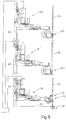
- the rig 1 comprises a soil bound foundation 2, e.g. a pile foundation comprising multiple piles 2a and a concrete foundation bed connected to said piles, e.g. concrete piles.
- a soil bound foundation 2 e.g. a pile foundation comprising multiple piles 2a and a concrete foundation bed connected to said piles, e.g. concrete piles.
- the rig 1 further comprises a pivot structure 3 that is secured to the foundation 2.
- the pivot structure 3 provides a single horizontal pivot axis 4.
- a motion base 5 is mounted on the pivot structure 3 and is pivotable about the horizontal pivot axis 4 relative to the foundation 2, e.g. allowing to simulate sea state induced roll motion when the rig would be installed appropriately on a floating drilling vessel.
- a drilling tower 10 is erected on the motion base 5.
- the tower has a tower structure embodied as a mast with a firing line 6 alongside and to the outside of the mast 10.
- the mast 10 has a foot that is secured to the pivotal motion base 5.
- the drilling tower 10 is provided with a hoisting device that is adapted to manipulate a drill string section in the vertical firing line 6.
- the hoisting device comprises a hoisting winch 11 and cable 12 connected to winch 11.
- a travelling block 13 is suspended from the cable 12, e.g. with a multiple fall arrangement between crown block 15 and the travelling block 13.
- the travelling block 13 supports a trolley 16 that is guided along vertical rails 17 extending along the side of the mast 10 facing the firing line 6.
- the trolley 16 carries a rotary topdrive device 18 that is adapted to impart rotary drive to a drill string section.
- the rig 1 further comprises a drilling tubulars storage, here a rotary storages 20, 21, that are each adapted for vertical storage of drilling tubulars, e.g. drill pipe stands.
- the tubulars storages 20, 21 are of the known carousel type in this example, but other embodiments with parallel setback slots are also envisaged.
- the rig 1 only has one such rotary storage, e.g. with a small stationary storage replacing the other rotary storage shown herein.
- the drilling tubulars rotary storage rack 20, 21 is rotatable mounted so as to rotate about a vertical axis.
- the drilling tubulars rotary storage rack 20, 21 includes slots for the storage of multiple tubulars in each drilling tubulars rotary storage rack in vertical orientation.
- the rack 20, 21 here includes a central vertical post and multiple disc members at different heights of the post, at least one disc being a fingerboard disc having tubulars storage slots, each slot having an opening at an outer circumference of the fingerboard disc allowing to introduce and remove a tubular from the storage slot.
- the tubulars rest with their lower end on a lowermost disc member.
- triple stands are stored in the rack 20, 21.
- the diameter of rack may be about 8 meters.
- a drive motor is present for drilling tubulars rotary storage rack 20, 21 that allow to rotate the drilling tubulars storage rack about its vertical axis.
- the rig 1 also comprises a tubulars racker device, here two such devices 140, 140', each arranged and configured to move drilling tubulars between the drilling tubulars storage device 20, 21 and the firing line 6 allowing for assembly and disassembly of a drill string section in the firing line.
- a tubulars racker device here two such devices 140, 140', each arranged and configured to move drilling tubulars between the drilling tubulars storage device 20, 21 and the firing line 6 allowing for assembly and disassembly of a drill string section in the firing line.
- the two tubular racking devices 140 and 140' are each mounted at a corner of the mast 10.
- the rig 1 further comprises a motion drive 50 adapted to impart cyclic pivoting motion about the horizontal pivot axis 4 to the assembly of the drilling tower 10, drilling tubulars storages 20, 21, and tubulars racker devices 140, 140' in order to simulate this assembly being subjected to sea state induced motion, e.g. to roll motion.
- a motion drive 50 adapted to impart cyclic pivoting motion about the horizontal pivot axis 4 to the assembly of the drilling tower 10, drilling tubulars storages 20, 21, and tubulars racker devices 140, 140' in order to simulate this assembly being subjected to sea state induced motion, e.g. to roll motion.
- the motion drive 50 comprises a strut 51 having an upper end pivotally attached to the drilling tower 10 at an elevated position thereof and having a lower end pivotally attached to a drive motor device 52.
- the drive motor device comprises a motor driven rocker arm 53 that is pivotally connected to the strut 51 and adapted to perform a cyclic rocking motion about a horizontal rocker arm axis 54.
- the motion drive may be adapted to impart a cyclic pivoting motion having a period in a range between 2 and 30 seconds.
- the motion drive may be adapted to impart a cyclic pivoting motion having a pivot angle relative to vertical of at least +/-1°.
- the single horizontal pivot axis 4 intersects the firing line 6.
- Counterweight elements 75 may be provided to the drilling tower 10, drilling tubulars storage 20, 21 or tubulars racker device 140,140' to balance the assembly of drilling tower 10, drilling tubulars storage 20, 21 and tubulars racker device 140,140' relative to axis 4.
- the total mass of the counterweight elements 75 can be adjusted in view of variation of the mass of tubulars stored in the storage, e.g. when just one storage is present at one side of the tower.
- the rig further comprises or is associated with a well 60 that is sunken into the soil at a position aligned with the firing line 6, e.g. a concrete lined well.
- the well 60 has a diameter greater than of drilling tubulars storable in the tubulars storage device, e.g. a diameter of at least one meter.
- a drill floor 25 may be provided, having a well center or opening therein through which a drill string passes into the well 60, along the firing line 6.
- each racking device 140, 140' has multiple, here three motion arm assemblies.
- a lower first racker motion arm assembly 141, 141' is provided as well as a second racker motion assembly 142, 142', operable at a greater height than the first tubular racker assembly.
- a third well center tool motion arm assembly 143, 143' is provided
- Each set of motion arm assemblies is arranged on a common vertical rail 145, 145' that is fixed to the mast 4, here each at a corner thereof.
- a drill pipe multi-joint tubular 115 is held by racker assemblies 142' and 141' in the firing line 6, thereby allowing to connect the tubular stand 115 to the drill string supported, e.g., by drill string slip device 130.
- Each of said assemblies 142' and 141' carries a tubular gripper member 142't and 141't at the end of the motion arm of the assembly.
- a gripper member that supports the weight of the gripped tubular and the other arm carries a centralizer that holds the tubular in the upright position.
- the lower motion arm assembly 143 of the other racker device 140 carries an iron roughneck device 150, herewith a spinner 151 thereon as well.
- the motion arm 141m is here embodied a telescopic extensible arm, the arm having a first arm segment 141m - 1 which is connected to the base 141b via a vertical axis bearing 147 allowing the motion arm 141m to revolve about this vertical axis. As is preferred this vertical axis forms the only axis of revolution of the motion arm.
- the motion arm has two telescoping additional arm segments 141m-2 and 141m-3, with the outer arm segment being provided with a connector 148 for a tubular gripper 141't and/or a well center tool (e.g. iron roughneck device 150).
- the rig may have a well center tools storage structure that is adapted to store therein the one or more well center tools, e.g. an iron roughneck device 150, 150' that are connectable to the motion arm of the lowermost motion arm assembly 143, 143'.
- a well center tools storage structure that is adapted to store therein the one or more well center tools, e.g. an iron roughneck device 150, 150' that are connectable to the motion arm of the lowermost motion arm assembly 143, 143'.
- Each tubular racking device comprises a vertical guide rail 145 onto which corresponding guide members of the base 141b of each tubular racker assembly engage.
- the base 141b carries four sets of each three rollers 149 of which two rollers 149 ride along opposed faces of a flange of the rails 145 and one roller rides along a lateral side of the flange.
- the racking device further comprises a vertical toothed rack 160 arranged parallel to this vertical guide rails 145.
- the toothed rack 160 is mounted on the rail 145, here on a front plate of the rail between the two flanges of the rail 145.
- the base 141b of the tubular racker assembly 141 is provided with one or more, here two, pinions engaging with this vertical toothed rack.
- the base is provided with one or more motors 162, here two, driving the pinions, so as to allow for a controlled vertical motion of the racker assembly 141.
- the one or more motors 162 driving the one or more pinions are electric motors.
- the motion arm assembly 143 holds iron roughneck device 150 above the well center for make-up or breaking up of connections between tubulars in the firing line 5.
- the other motion arm assembly 143' can be equipped with a second iron roughneck device, which is then already prepared for handling different diameter tubulars.
- the mast of the tower structure is a latticed tower structure and the firing line 6 is outside of and alongside a side of the tower structure.
- the side facing the firing line is covered with a panel.
- An operator's cabin can be mounted stationary on the foundation.
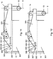
- the pendulum system 55 comprises a soil bound foundation 65, e.g. a pile foundation comprising multiple piles, e.g. like piles 2a, and a concrete foundation bed connected to said piles, e.g. concrete piles.
- a soil bound foundation 65 e.g. a pile foundation comprising multiple piles, e.g. like piles 2a, and a concrete foundation bed connected to said piles, e.g. concrete piles.
- the pendulum system 55 further comprises a frame 56 secured to the foundation 65.
- the frame is a metal frame.
- the frame may have a height between 1 and 8 meters, e.g. about 6 meters.
- a compound pendulum 57 is suspended from said frame 56 and is swingable relative to the frame about at least one horizontal swing axis 58, e.g. allowing the compound pendulum 57 to swing.
- the compound pendulum 57 has a height between 1 and 5 meters.
- the pendulum system 55 further comprises a strut 51 having an upper end pivotally attached to the drilling tower at an elevated position thereof and having a lower end pivotally attached to the compound pendulum by means of a pivot point 59.
- the pendulum system 55 further comprises a drive motor 76.
- the drive motor 76 is adapted to supply energy to impart a cyclic motion to the assembly of compound pendulum 57, strut 51, motion base 5, drilling tower 10, drilling tubulars storage 20, 21 and tubulars racker device 140, 140', said cyclic motion having a frequency that is equal to the resonance frequency of the assembly.
- the cyclic motion imparted to the assembly of the drilling tower 10, drilling tubulars storage 20, 21 and tubulars racker device 140, 140' is a cycling motion is about said at least one horizontal pivot axis 4 of the pivot structure 3.
- the drive motor 76 comprises a hydraulic cylinder.
- said hydraulic cylinder 76 is connected at one end to the frame 56 and at the other end to the compound pendulum 57.
- the pendulum system may further comprise weight elements 61 that can be added to and removed from the compound pendulum 57 to adjust the resonance frequency and/or acceleration of the assembly of compound pendulum 57, strut 51, motion base 5, drilling tower 10, drilling tubulars storage 20, 21 and tubulars racker device 140,140'.
- the compound pendulum 57 with weight elements 61 comprises:
- the drilling rig pivot structure 3 may, as preferred, provide a single horizontal pivot axis 4 while the compound pendulum 57 is swingable about one horizontal swing axis 58.
- An embodiment of the compound pendulum swingable about one horizontal swing axis 58 is shown in figures 6 and 7 .
- Preferably said horizontal pivot axis 4 and said horizontal swing axis 58 are substantially parallel.
- the weight of the compound pendulum 57 comprising weight elements 61 is between 100 ton and 500 ton, e.g. variable between 150 tonnes and 300 tonnes by means of the weight elements.
- the frame comprises a link 74 having one end attached to the frame 56 and allowing the other end to be attached to the compound pendulum 57 by means of the lock pin 62.
- Said lock pin or other lock member locks the compound pendulum 57 to the frame 56, to prevent motion of the assembly of compound pendulum 57, strut 51, motion base 5, drilling tower 10, drilling tubulars storage 20, 21 and tubulars racker device 140, 140', e.g. when the rig is not in use or when static tests are performed.
- the lock pin 62 should be removed or disengaged to allow cyclic motion of the compound pendulum 57 relative to the frame 56.
- the pendulum system 55 may further comprise load measurement means 63, e.g. a load measurement pin, to determine the load imparted on the compound pendulum 57 by an imbalance of the assembly of drilling tower 10, drilling tubulars storage 20,21 and tubulars racker device 140,140'.
- load measurement means 63 e.g. a load measurement pin
- the frame 56 comprises frame parts 56a, 56b, 56c, 56d, which are pivotally attached at pivot points 66, 67, 68, in order to adjust the position of the pivot point 59 that connects strut 51 and compound pendulum 57 and thereby to impart to the motion base 5 a stationary non-zero pivot angle relative to horizontal.
- the relative positions of said frame parts is driven by hydraulic cylinder 64.
- the pendulum system 55 may further comprise braking means 76 to bring the assembly of compound pendulum 57, strut 51, motion base 5, drilling tower 10, drilling tubulars storage 20, 21 and tubulars racker device 140,140' to hold.
- the hydraulic cylinder 76 also acts as a braking means when suitably operated.
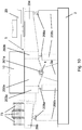
- the rig 1 comprises a soil-bound foundation 2 and secured to said foundation a pivot structure 3 including a front pivot structure 3a and a rear pivot structure 3b.
- the rig 1 further comprises a single pivot axis 4 along which a front pivot pin 201a a rear pivot pin 201b are provided, both pins preferably being made of steel and e.g. having a diameter between 50 and 100 cm, e.g. 60 cm. Said front pivot pin 201 is provided on the front pivot structure 3a, said rear pivot pin on the rear pivot structure 3b.
- the rig 1 further comprises a motion base 5 mounted on the front pivot pin 201a and rear pivot pin 201b and pivotable about pivot axis 4 relative to the foundation.
- the rig 1 further comprises a motion drive 50 to impart cyclic motion about said pivot axis 4.
- the motion base 5 comprises a front pivot connection element 202a, pivotally attached to the front pivot pin 201a, with a front surface facing the firing line and well 60 and two side surfaces and a rear pivot connection element 202b, pivotally attached to the rear pivot pin 201b, with a front surface facing the well 60 and two side surfaces.
- the motion base 5 further comprises two beams 203a, 203b placed substantially parallel to the pivot axis 4 and substantially parallel to each other at a distance from each other, each rigidly connected to a side surface of the front pivot connection element 202a and a side surface of the rear pivot connection element 202b.
- the beams 203a, 203b extend beyond the front pivot element 202a over a distance exceeding the distance between the front pivot connection element 202a and the well 60, to allow one or more tools used in drilling activities, such as clamps or rotaries, to be placed in the firing line 6 by placing said one or more tools in the region between both beams 203a, 203b supported by said beams 203a, 203b, in order to perform tests on or using said one or more tools.
- the beams 203a, 203b extend beyond the rear pivot connection element 202b, here to permit one or more winches 11 to be placed in the region between both beams 203a, 203b supported by both beam 203a, 203b.
- the beams 203a, 203b each have a height between 1 and 3 m, a width between 0.5 m and 2 m and a length between 10 and 35 meter, e.g. about 25 m long, and are a distance of between 2 and 10 m apart, e.g. about 6 m.
- the motion base 5 further comprises a drilling tubular storage frame 204 adapted to support drilling tubular storage 20, said drilling tubular storage frame being rigidly attached to one of two beams 203a,203b, here beam 203b.
- the frame extends primarily in the horizontal plane, e.g. between 5 and 10 m in both directions, and comprises two metal beams at right angles to beam 203b, interconnected by two beams parallel to beam 203b.
- the motion base 5 further comprises a counterweight element frame 205 rigidly attached to beam 203a and extending substantially perpendicular to the pivot axis 4 in a substantially horizontal direction.
- the counterweight element frame 205 is adapted to hold counterweight elements 75 at a position offset horizontally from the pivot axis 4, for instance between 2 and 15 m offset horizontally from the pivot axis, e.g. 10 m.
- the counterweight element frame 205 is provided at the other side of the pivot axis than drilling tubular storage frame 204 to permit balancing the assembly of drilling tower 10, tubulars racker device 140,140' and drilling tubulars storage 20 by means of said counterweight elements 75.
- the drilling tower 10 is supported by the front and rear pivot elements 202a, 202b and the two beams 203a, 203b.
- one or more temporary supports 208 can be placed underneath the motion base, e.g. underneath the beams 203a,203b, drilling tubulars storage frame 204 and/or counterweight elements frame 205.
- these temporary supports comprise a number of, here four, hydraulic jacks 208a each placed on or integrated with a removable support 208b.
- temporary supports can be integrated with the motion bases, e.g. embodied as hydraulic extendable legs of the motion base.
- the well 60 may contain a staircase, e.g. a spiralling staircase, e.g. to the bottom of the well 60.
- a staircase e.g. a spiralling staircase, e.g. to the bottom of the well 60.
- a lift e.g. with a vertical guide rail, in the well to allow access of personnel to the bottom of the well.
- one or more landings may be provided at different heights within the well 60.
- the well 60 can comprise a bottom 61 provided with one or more premade drilling holes, e.g. the bottom made of reinforced concrete or steel. In the figure 9 four holes are shown.
- the premade holes allow for drilling holes 206 into the soil below the bottom of the well, e.g. several hundreds of metres deep. Such drilling holes 206 can be drilled and can subsequently be filled to permit repeated drilling.
- the bottom 61 of the well 60 may comprise attachment means 207, e.g. a hook or eye plate, to which an object, e.g. a cable can be attached, in order to perform tests on or involving the hoisting device of the drilling tower 10.
- attachment means 207 e.g. a hook or eye plate
- the well 60 can be used for subjecting an object to a tensile test, with the object being secured between the attachment means 207 and the hoisting device, and the hoisting device being operated to place the object under a tensile load.
- the well may also be flooded, so that such testing can be done underwater, e.g. to test underwater behaviour of an object whilst subjected to tensile load.
- the drilling tower 10 may comprise a laterally extendable top section. With reference to figures 11 and 12 this embodiment of the drilling tower 10 will be discussed.
- the drilling tower 10 comprises a mast 301 erected on the motion base 5.
- the drilling tower 10 further comprises one or more hoisting winches 11, e.g. attached to the motion base 5, and one or more hoisting cables 12 driven by the one or more winches 11.
- the drilling tower 10 further comprises a fixed top frame or top member 302 rigidly attached to the top of said mast, said fixed frame or member 302 comprising one or more rear pulleys 303 to guide said one or more cables 12 from said one or more winches over the top of the drilling tower 11.
- the fixed frame 302 further comprises heave compensator path pulleys 304 to guide said cable 12 to and from a heave compensator cylinder (not shown), here provided in the interior of the mast 301.
- the drilling tower 10 further comprises a movable or extendable top frame 305.
- This movable top frame 305 is movable with respect to the fixed top frame 302 towards and away from the mast 301 along a direction substantially parallel to the pivot axis of the test drilling rig 4 in order to be able to vary the location of the firing line relative to the structure of the tower.
- the drilling tower 10 here further comprises at least one hydraulic cylinder 306 attached at one end to the fixed top frame 302 and attached to the movable top frame 305 at the other end, said hydraulic cylinder 306 being adapted to move the movable top frame 305 with respect to the fixed top frame 302.
- the interface between fixed frame 302 and movable frame 305 may for instance be embodied as a skidding arrangement or comprise a rail on top of the fixed frame 302 and wheels underneath the movable frame 305 to move the movable frame.
- the drilling tower further comprises a locking mechanism to maintain the position of the movable top frame 305 with respect to the fixed top frame.
- Said locking mechanism here comprises a locking beam 307 rigidly attached to the movable frame part, a locking pin 308 to be placed through holes in the locking beam 307, and a lock pin holder 309 rigidly attached to the fixed top frame 302 to maintain the pin 308 and thereby the locking beam 307 and the full movable top frame section 305 in position.
- the drilling tower further comprises one or more crown blocks 15 and one or more travelling pulley blocks 13 along which cable or cables 12 pass to raise and lower the travelling pulley blocks 13.
- a topdrive can be suspended from the block or blocks 13.
- the one or more crown blocks 15 are secured to the movable top frame 305, here at the end of the movable top frame 305 approximately above the well 60 to guide the cable 12.
- the extension and retraction of the top section of the drilling tower as described above moves the crown block 15 and travelling block 13 further away or closer to the mast 301, for example by between 1 and 5 m, e.g. allowing for adjustment over a range of at least 1 meter, e.g. at least 2 m.
- the position of the firing line 6 is in this way adjusted.
Claims (16)
- Engin de forage pour test de simulation de mouvement marin dynamique sur terre (1) comprenant :- une base fixée au sol (2), comme une base sur pilotis comprenant plusieurs pilotis (2a),- une structure de pivot (3) fixée sur ladite base, ladite structure de pivot offrant au moins un axe de pivot horizontal (4),- une base de mouvement (5) montée sur ladite structure de pivot et qui peut pivoter autour dudit au moins un axe de pivot horizontal par rapport à la base, afin de simuler par exemple un mouvement de roulis induit par l'état de la mer,- une tour de forage (10) érigée sur ladite base de mouvement (5) et ayant un support qui est fixé sur ladite base de mouvement, la tour de forage étant munie d'un dispositif de levage (11, 12) adapté pour manipuler une section de colonne de forage dans une conduite de déclenchement verticale (6),- un système de stockage de tubulaires de forage (20, 21) adapté pour le stockage vertical d'un ou plusieurs tubulaires de forage, comme des supports de tiges de forage (115), ledit système de stockage de tubulaires étant fixé sur ladite base de mouvement,- un dispositif de manutention de tubulaires (140, 140') prévu et configuré pour déplacer des tubulaires de forage entre le système de stockage de tubulaires de forage et la conduite de déclenchement de façon à permettre l'assemblage et le démontage d'une section de colonne de forage dans la conduite de déclenchement (6),- un entraînement (50 ; 55) adapté pour transmettre un mouvement de pivotement cyclique autour dudit au moins axe de pivot horizontal (4) à l'ensemble de tour de forage, de système de stockage de tubulaires de forage, et de dispositif de manutention de tubulaires afin de simuler ledit ensemble qui est soumis au mouvement induit par l'état de la mer.
- Engin de forage selon la revendication 1, comprenant en outre un puits (60) creusé dans le sol et aligné avec la conduite de déclenchement (6), comme un puits à parois en acier, ledit puits ayant par exemple un diamètre supérieur à celui des tubulaires de forage qui peuvent être stockés dans le dispositif de stockage de tubulaires, ledit puits comprenant par exemple un fond muni d'un ou plusieurs orifices pré-percés en vue d'un forage plus en profondeur dans le sol, sous le fond du puits, le fond dudit puits comprenant par exemple un moyen de fixation destiné à fixer un objet, comme un câble, ledit puits étant adapté pour être rempli d'eau.
- Engin de forage selon la revendication 1 ou 2, dans lequel ledit entraînement (50 ; 55) est adapté pour transmettre un mouvement de pivotement cyclique ayant une durée comprise entre 2 et 30 secondes.
- Engin de forage selon l'une quelconque des revendications 1 à 3, dans lequel ledit entraînement (50 ; 55) est adapté pour transmettre un mouvement de pivotement cyclique ayant un angle de pivotement par rapport à la verticale d'au moins +/- 1°.
- Engin de forage selon l'une quelconque des revendications 1 à 4, dans lequel la structure de pivot (3) offre un seul axe de pivot horizontal (4), qui croise de préférence la conduite de déclenchement (6).
- Engin de forage selon la revendication 1, dans lequel l'entraînement (50) est un système de pendule (55) comprenant :- un châssis (56) fixé sur une base fixée au sol (65), comme une base sur pilotis comprenant plusieurs pilotis,- un pendule de gravité (57) suspendu audit châssis (56), le pendule de gravité pouvant se balancer par rapport au châssis autour d'au moins un axe de balancement horizontal (58),- un étai (51) ayant une extrémité, comme une extrémité supérieure, relié de manière pivotante à la tour de forage (10), comme par exemple à un emplacement élevé de celle-ci, et ayant une autre extrémité, comme une extrémité inférieure, reliée de manière pivotante au pendule de gravité à l'aide d'un raccord de pivot qui offre un point de pivot (59) décalé par rapport audit au moins un axe de basculement entre le pendule de gravité et le châssis,- un moteur d'entraînement (76),dans lequel le moteur d'entraînement est adapté pour fournir de l'énergie afin de transmettre un mouvement cyclique à l'ensemble de pendule de gravité, d'étai, de base de mouvement, de tour de forage, de système de stockage de tubulaires et de dispositif de manutention de tubulaires.
- Engin de forage selon la revendication 6, dans lequel le système de pendule (55) comprend en outre un ou plusieurs éléments de poids (61) qui peuvent être ajoutés à et retirés du pendule de gravité (57) afin d'ajuster la fréquence de résonance et/ou l'accélération de l'ensemble de pendule de gravité, d'étai, de base de mouvement, de tour de forage, de système de stockage de tubulaires et de dispositif de manutention de tubulaires.
- Engin de forage selon l'une quelconque des revendications 1 à 6, dans lequel l'engin de forage, comme par exemple le système de pendule (55) de celui-ci, comprend en outre un ou plusieurs éléments de contrepoids (75) qui peuvent être ajoutés à la base de mouvement (5), à la tour de forage (10), au système de stockage de tubulaires (20, 21) ou au dispositif de manutention de tubulaires (140,140') afin d'équilibrer l'ensemble de base de mouvement, de tour de forage, de système de stockage de tubulaires de forage et de dispositif de manutention de tubulaires, par rapport à l'axe de pivot horizontal (4).
- Engin de forage selon la revendication 6, dans lequel la structure de pivot d'engin de forage offre un seul axe de pivot horizontal (4), qui croise de préférence la conduite de déclenchement, et dans lequel le pendule de gravité peut basculer autour d'un axe de basculement horizontal (58), ledit axe de pivot horizontal (4) et ledit axe de basculement horizontal étant de préférence parallèles.
- Engin de forage selon la revendication 6, dans lequel le châssis (56) comprend une pluralité de parties de châssis réglables les unes par rapport aux autres afin d'ajuster la position du raccord de pivot qui relie l'étai (51) et le pendule de gravité (57), et de transmettre ainsi à la base de mouvement (5) un angle de pivot non nul stationnaire par rapport à l'horizontale.
- Engin de forage selon l'une quelconque des revendications 1 à 10, dans lequel la tour de forage (10) comprend un ou plusieurs rails verticaux (17) et un chariot (13) guidé verticalement par ledit ou lesdits rails, ledit chariot, de préférence, portant et/ou étant adapté pour porter un dispositif d'entraînement supérieur rotatif adapté pour transmettre une force de rotation à une section de colonne de forage, ledit chariot et/ou ledit entraînement supérieur rotatif étant par exemple suspendu à un câble d'entraînement de treuil.
- Engin de forage selon l'une quelconque des revendications 1 à 11, dans lequel la tour (10) possède une structure de tour et la conduite de déclenchement (6) se trouve à l'extérieur de et le long d'un côté de la structure de tour, la structure de tour étant par exemple un mât (301) ayant un contour à parois fermées.
- Engin de forage selon l'une quelconque des revendications 1 à 12, dans lequel l'engin de forage comprend un plancher de forage (25) et un dispositif de glissement de colonne de tubulaires (130), ledit dispositif de glissement étant adapté pour supporter le poids d'une colonne de tubulaires, comme une colonne de forage, suspendue à celui-ci le long de la conduite de déclenchement, comme par exemple dans le puits selon la revendication 2.
- Engin de forage selon la revendication 5, dans lequel la base de mouvement comprend deux traverses (203a, 203b) parallèles l'une à l'autre et espacées, lesdites traverses étant parallèles à l'axe de pivot (4) de ladite base de mouvement (5), lesdites traverses s'étendant depuis la tour de forage (10) vers la conduite de déclenchement (6) et étant configurées pour placer et maintenir un ou plusieurs outils, comme un plateau rotatif, un dispositif de glissement, un dispositif de fixation, etc. dans la conduite de déclenchement.
- Engin de forage (1) selon l'une quelconque des revendications 1 à 14, dans lequel l'engin de forage comprend une structure de tour (10) avec la conduite de déclenchement (6) à l'extérieur de et le long d'un côté de la structure de tour, et dans lequel l'engin de forage comprend un dispositif de stockage (20) destiné au stockage vertical de tubulaires de forage, ledit dispositif de stockage de tubulaires étant prévu sur un côté de la structure de tour différent du côté conduite de déclenchement, et dans lequel l'engin de forage comprend un dispositif de manutention de tubulaires (140) configuré pour déplacer les tubulaires de forage entre le dispositif de stockage et la conduite de déclenchement, et dans lequel l'engin de forage comprend un châssis à éléments de contrepoids (205) destiné à maintenir des éléments de contrepoids (75), dans lequel la structure de stockage de tubulaires et le châssis à éléments de contrepoids sont positionnés au niveau des côtés opposés du plancher de forage (25) .
- Procédé d'exécution d'un test qui utilise un engin de forage pour test de simulation de mouvement marin dynamique sur terre selon l'une quelconque des revendications 1 à 15, dans lequel l'entraînement (50 ; 55) transmet un mouvement de pivotement cyclique autour du au moins un, ou d'un seul, axe de pivot horizontal (4) à l'ensemble de tour de forage (10), de système de stockage de tubulaires de forage (20, 21) et de dispositif de manutention de tubulaires (140, 140') afin de simuler ledit ensemble qui est soumis à un mouvement induit par l'état de la mer.
Applications Claiming Priority (3)
| Application Number | Priority Date | Filing Date | Title |
|---|---|---|---|
| NL2013685A NL2013685B1 (en) | 2014-10-24 | 2014-10-24 | Land based dynamic sea motion simulating test drilling rig and method. |
| NL2014405 | 2015-03-05 | ||
| PCT/NL2015/050732 WO2016064273A1 (fr) | 2014-10-24 | 2015-10-22 | Procédé et appareil de forage d'essai simulant le mouvement dynamique de la mer basé à terre |
Publications (2)
| Publication Number | Publication Date |
|---|---|
| EP3209848A1 EP3209848A1 (fr) | 2017-08-30 |
| EP3209848B1 true EP3209848B1 (fr) | 2019-07-24 |
Family
ID=54937340
Family Applications (1)
| Application Number | Title | Priority Date | Filing Date |
|---|---|---|---|
| EP15813602.8A Active EP3209848B1 (fr) | 2014-10-24 | 2015-10-22 | Procédé et appareil de forage d'essai simulant le mouvement dynamique de la mer basé à terre |
Country Status (3)
| Country | Link |
|---|---|
| US (1) | US9857277B2 (fr) |
| EP (1) | EP3209848B1 (fr) |
| WO (1) | WO2016064273A1 (fr) |
Families Citing this family (15)
| Publication number | Priority date | Publication date | Assignee | Title |
|---|---|---|---|---|
| CN106482925B (zh) * | 2016-09-23 | 2018-12-07 | 燕山大学 | 模拟钻柱和外筒同时旋转诱发流场的实验及测量装置 |
| CN109300353B (zh) * | 2016-10-18 | 2021-07-27 | 浙江海洋大学 | 模拟海上作业工况的海洋工程试验平台装置 |
| CN106498987B (zh) * | 2016-10-21 | 2018-06-19 | 东南大学 | 一种表征浅基础动力特性的现场动力试验装置 |
| KR102136166B1 (ko) * | 2018-08-09 | 2020-07-21 | 재단법인한국조선해양기자재연구원 | Lng 벙커링 기자재 시험평가 설비 |
| CN109319064B (zh) * | 2018-10-15 | 2023-08-15 | 烟台宏远氧业股份有限公司 | 开式钟 |
| CN110318730B (zh) * | 2019-06-25 | 2023-05-02 | 中国石油化工股份有限公司 | 高自由度多功能下井仪器试验台 |
| WO2021040948A1 (fr) * | 2019-08-29 | 2021-03-04 | Cameron International Corporation | Mât de support de treuil de forage incliné |
| CN111426496B (zh) * | 2020-04-05 | 2021-05-25 | 新疆正通石油天然气股份有限公司 | 一种变径井眼中屈曲管柱钻进模拟装置 |
| CN111594144A (zh) * | 2020-05-19 | 2020-08-28 | 德州联合石油科技股份有限公司 | 螺杆钻具及垂直钻井工具试验方法与模拟井斜测试设备 |
| CN113218686B (zh) * | 2021-04-29 | 2021-11-23 | 东北石油大学 | 一种深海水平气井钻柱动力学行为研究试验台 |
| CN113465964B (zh) * | 2021-06-16 | 2022-04-19 | 天津大学 | 一种海上高耸塔器的摇摆试验装置 |
| CN113465965B (zh) * | 2021-06-16 | 2022-08-12 | 天津大学 | 一种海上高耸塔器的自升式摇摆试验装置 |
| CN113884323A (zh) * | 2021-09-23 | 2022-01-04 | 武汉船用机械有限责任公司 | 海上波浪补偿吊机测试装置及测试方法 |
| CN114264492B (zh) * | 2021-12-02 | 2023-11-21 | 中煤科工集团西安研究院有限公司 | 一种钻机起拔与回转复合测试系统及方法 |
| CN114486229B (zh) * | 2022-03-31 | 2022-06-21 | 山东普瑞思德石油技术有限公司 | 一种可适用多尺寸管柱的模拟起下设备 |
Citations (3)
| Publication number | Priority date | Publication date | Assignee | Title |
|---|---|---|---|---|
| US3677016A (en) * | 1971-02-08 | 1972-07-18 | Chicago Bridge & Iron Co | Corrosion protection for well casing of offshore structure |
| WO2000011305A1 (fr) * | 1998-08-20 | 2000-03-02 | Overseas Industries Ltd. | Appareil de forage hydraulique |
| US20110174545A1 (en) * | 2010-01-15 | 2011-07-21 | Vermeer Manufacturing Company | Drilling machine and method |
Family Cites Families (17)
| Publication number | Priority date | Publication date | Assignee | Title |
|---|---|---|---|---|
| US3791628A (en) * | 1972-07-26 | 1974-02-12 | Ocean Science & Eng | Motion compensated crown block system |
| US3930374A (en) * | 1975-03-06 | 1976-01-06 | Hoppe Charles W | Dynamic ballast and stabilization system |
| US4883388A (en) * | 1985-10-03 | 1989-11-28 | Cherbonnier T Dave | Load compensating system |
| US5209302A (en) * | 1991-10-04 | 1993-05-11 | Retsco, Inc. | Semi-active heave compensation system for marine vessels |
| WO1999019593A2 (fr) * | 1997-10-15 | 1999-04-22 | Ingersoll-Rand Company | Systeme d'avance automatique pour forage rotary |
| US6321596B1 (en) * | 1999-04-21 | 2001-11-27 | Ctes L.C. | System and method for measuring and controlling rotation of coiled tubing |
| WO2001029366A1 (fr) | 1999-10-19 | 2001-04-26 | Roodenburg, Joop | Mecanisme de levage, avec compensateur installe dans un systeme de levage par cable |
| US6926103B1 (en) * | 2001-07-02 | 2005-08-09 | Itrec B.V. | Splittable block on a derrick |
| US6763898B1 (en) | 2002-08-06 | 2004-07-20 | Itrec B.V. | Dual hoist system |
| US20100307401A1 (en) | 2007-10-11 | 2010-12-09 | Itrec B.V. | Vessels with roll damping mechanism |
| EP2462304A2 (fr) * | 2009-08-07 | 2012-06-13 | National Oilwell Varco, L.P. | Appareil de forage avec stabilisateurs articulés rétractables |
| CN102980732B (zh) * | 2012-11-06 | 2016-04-13 | 上海交通大学 | 模拟均匀流下深海立管横向自激振动的试验装置 |
| US8839570B1 (en) * | 2013-03-13 | 2014-09-23 | Nabors Drilling International Limited | Self-elevating mast employing actuators |
| US9631442B2 (en) * | 2013-12-19 | 2017-04-25 | Weatherford Technology Holdings, Llc | Heave compensation system for assembling a drill string |
| CN103743534B (zh) * | 2014-01-14 | 2016-08-31 | 中国科学院武汉岩土力学研究所 | 一种盐穴储油库水溶造腔管柱动力特性模型试验装置 |
| US10053928B2 (en) * | 2014-03-03 | 2018-08-21 | Itrec B.V. | Offshore drilling vessel and method |
| CN103994757B (zh) * | 2014-06-09 | 2015-04-08 | 中国海洋大学 | 一种往复式海洋微结构剖面仪 |
-
2015
- 2015-10-22 EP EP15813602.8A patent/EP3209848B1/fr active Active
- 2015-10-22 WO PCT/NL2015/050732 patent/WO2016064273A1/fr active Application Filing
- 2015-10-26 US US14/922,828 patent/US9857277B2/en active Active
Patent Citations (3)
| Publication number | Priority date | Publication date | Assignee | Title |
|---|---|---|---|---|
| US3677016A (en) * | 1971-02-08 | 1972-07-18 | Chicago Bridge & Iron Co | Corrosion protection for well casing of offshore structure |
| WO2000011305A1 (fr) * | 1998-08-20 | 2000-03-02 | Overseas Industries Ltd. | Appareil de forage hydraulique |
| US20110174545A1 (en) * | 2010-01-15 | 2011-07-21 | Vermeer Manufacturing Company | Drilling machine and method |
Non-Patent Citations (2)
| Title |
|---|
| MADS GRINROD: "Continuous Motion Rig. A Detailed Study of a 750 ton capacity , 3600 m/hr trip speed rig", SPE, 1 January 2011 (2011-01-01), XP055545539, ISBN: 978-1-55563-326-4, DOI: 10.2118/139403-MS * |
| SIV M ?SEN: "Introduction to IRIS lab tour Introduction to IRIS tour", 2 June 2014 (2014-06-02), XP055195939, Retrieved from the Internet <URL:http://www.force.org/Global/IOGR/Improve%20EOR%20competence/10-20140526%20Force%20IRIS%20tour.pdf> [retrieved on 20150615] * |
Also Published As
| Publication number | Publication date |
|---|---|
| US20160116376A1 (en) | 2016-04-28 |
| EP3209848A1 (fr) | 2017-08-30 |
| US9857277B2 (en) | 2018-01-02 |
| WO2016064273A1 (fr) | 2016-04-28 |
Similar Documents
| Publication | Publication Date | Title |
|---|---|---|
| EP3209848B1 (fr) | Procédé et appareil de forage d'essai simulant le mouvement dynamique de la mer basé à terre | |
| CA2783675C (fr) | Appareil de forage multifonctionnel de trous multiples | |
| JP4654324B2 (ja) | 水底削岩システム及び水底下方の地層を削岩する方法 | |
| US8936424B1 (en) | Vertical pipe handler with pivoting arms and smart grip | |
| CA2824963C (fr) | Procede et appareil pour forer des trous auxiliaires | |
| CN105019930B (zh) | 一种矿用液压支架组装平台 | |
| BRPI0917536B1 (pt) | Plataforma com múltiplas funções e método para executar as operações da plataforma em uma pluralidade de localizações de boca de poço separadas | |
| AU2012204091A1 (en) | Method for providing a foundation for a mass located at height, and a positioning frame for performing the method | |
| CN104520524A (zh) | 钻井设备以及组装和拆卸方法 | |
| CN106194022A (zh) | 一种用于综采工作面过断层的便携式钻孔装置及使用方法 | |
| CN112302534B (zh) | 一种边坡锚杆施工装置及快速施工方法 | |
| CN110656890B (zh) | 深水地质钻探套管和套管吊放系统及套管吊放方法 | |
| CN102061889B (zh) | 一种钻机塔架起塔装置及使用方法 | |
| NO342128B1 (no) | Rørhåndteringsapparat | |
| CN116816256A (zh) | 一种岩土勘察用智能化钻探装置及施工方法 | |
| CN103556626A (zh) | 一种用于大直径钻孔灌注桩钢筋笼吊装的吊挂结构 | |
| CN109424324A (zh) | 钻机高容量井架 | |
| NL2013685B1 (en) | Land based dynamic sea motion simulating test drilling rig and method. | |
| CN201874478U (zh) | 一种钻机塔架起塔装置 | |
| CN206328039U (zh) | 旋挖钻机干钻成孔钢筋网吊装固定装置 | |
| RU2647522C2 (ru) | Мобильная буровая установка | |
| CN213805399U (zh) | 一种高度可调的灌浆台车 | |
| AU2015218160B2 (en) | Drilling and boring system for diamond drilling | |
| CN214832698U (zh) | 一种预制桩沉桩设备 | |
| CN217780612U (zh) | 一种既有建筑拆除用整体吊装结构 |
Legal Events
| Date | Code | Title | Description |
|---|---|---|---|
| STAA | Information on the status of an ep patent application or granted ep patent |
Free format text: STATUS: THE INTERNATIONAL PUBLICATION HAS BEEN MADE |
|
| PUAI | Public reference made under article 153(3) epc to a published international application that has entered the european phase |
Free format text: ORIGINAL CODE: 0009012 |
|
| STAA | Information on the status of an ep patent application or granted ep patent |
Free format text: STATUS: REQUEST FOR EXAMINATION WAS MADE |
|
| 17P | Request for examination filed |
Effective date: 20170509 |
|
| AK | Designated contracting states |
Kind code of ref document: A1 Designated state(s): AL AT BE BG CH CY CZ DE DK EE ES FI FR GB GR HR HU IE IS IT LI LT LU LV MC MK MT NL NO PL PT RO RS SE SI SK SM TR |
|
| AX | Request for extension of the european patent |
Extension state: BA ME |
|
| DAV | Request for validation of the european patent (deleted) | ||
| DAX | Request for extension of the european patent (deleted) | ||
| GRAP | Despatch of communication of intention to grant a patent |
Free format text: ORIGINAL CODE: EPIDOSNIGR1 |
|
| STAA | Information on the status of an ep patent application or granted ep patent |
Free format text: STATUS: GRANT OF PATENT IS INTENDED |
|
| INTG | Intention to grant announced |
Effective date: 20190219 |
|
| GRAS | Grant fee paid |
Free format text: ORIGINAL CODE: EPIDOSNIGR3 |
|
| GRAA | (expected) grant |
Free format text: ORIGINAL CODE: 0009210 |
|
| STAA | Information on the status of an ep patent application or granted ep patent |
Free format text: STATUS: THE PATENT HAS BEEN GRANTED |
|
| AK | Designated contracting states |
Kind code of ref document: B1 Designated state(s): AL AT BE BG CH CY CZ DE DK EE ES FI FR GB GR HR HU IE IS IT LI LT LU LV MC MK MT NL NO PL PT RO RS SE SI SK SM TR |
|
| REG | Reference to a national code |
Ref country code: GB Ref legal event code: FG4D |
|
| REG | Reference to a national code |
Ref country code: CH Ref legal event code: EP |
|
| REG | Reference to a national code |
Ref country code: DE Ref legal event code: R096 Ref document number: 602015034467 Country of ref document: DE |
|
| REG | Reference to a national code |
Ref country code: AT Ref legal event code: REF Ref document number: 1158402 Country of ref document: AT Kind code of ref document: T Effective date: 20190815 |
|
| REG | Reference to a national code |
Ref country code: IE Ref legal event code: FG4D |
|
| REG | Reference to a national code |
Ref country code: NL Ref legal event code: FP |
|
| REG | Reference to a national code |
Ref country code: LT Ref legal event code: MG4D |
|
| REG | Reference to a national code |
Ref country code: NO Ref legal event code: T2 Effective date: 20190724 |
|
| REG | Reference to a national code |
Ref country code: AT Ref legal event code: MK05 Ref document number: 1158402 Country of ref document: AT Kind code of ref document: T Effective date: 20190724 |
|
| PG25 | Lapsed in a contracting state [announced via postgrant information from national office to epo] |
Ref country code: BG Free format text: LAPSE BECAUSE OF FAILURE TO SUBMIT A TRANSLATION OF THE DESCRIPTION OR TO PAY THE FEE WITHIN THE PRESCRIBED TIME-LIMIT Effective date: 20191024 Ref country code: AT Free format text: LAPSE BECAUSE OF FAILURE TO SUBMIT A TRANSLATION OF THE DESCRIPTION OR TO PAY THE FEE WITHIN THE PRESCRIBED TIME-LIMIT Effective date: 20190724 Ref country code: LT Free format text: LAPSE BECAUSE OF FAILURE TO SUBMIT A TRANSLATION OF THE DESCRIPTION OR TO PAY THE FEE WITHIN THE PRESCRIBED TIME-LIMIT Effective date: 20190724 Ref country code: HR Free format text: LAPSE BECAUSE OF FAILURE TO SUBMIT A TRANSLATION OF THE DESCRIPTION OR TO PAY THE FEE WITHIN THE PRESCRIBED TIME-LIMIT Effective date: 20190724 Ref country code: PT Free format text: LAPSE BECAUSE OF FAILURE TO SUBMIT A TRANSLATION OF THE DESCRIPTION OR TO PAY THE FEE WITHIN THE PRESCRIBED TIME-LIMIT Effective date: 20191125 Ref country code: FI Free format text: LAPSE BECAUSE OF FAILURE TO SUBMIT A TRANSLATION OF THE DESCRIPTION OR TO PAY THE FEE WITHIN THE PRESCRIBED TIME-LIMIT Effective date: 20190724 Ref country code: SE Free format text: LAPSE BECAUSE OF FAILURE TO SUBMIT A TRANSLATION OF THE DESCRIPTION OR TO PAY THE FEE WITHIN THE PRESCRIBED TIME-LIMIT Effective date: 20190724 |
|
| PG25 | Lapsed in a contracting state [announced via postgrant information from national office to epo] |
Ref country code: AL Free format text: LAPSE BECAUSE OF FAILURE TO SUBMIT A TRANSLATION OF THE DESCRIPTION OR TO PAY THE FEE WITHIN THE PRESCRIBED TIME-LIMIT Effective date: 20190724 Ref country code: GR Free format text: LAPSE BECAUSE OF FAILURE TO SUBMIT A TRANSLATION OF THE DESCRIPTION OR TO PAY THE FEE WITHIN THE PRESCRIBED TIME-LIMIT Effective date: 20191025 Ref country code: RS Free format text: LAPSE BECAUSE OF FAILURE TO SUBMIT A TRANSLATION OF THE DESCRIPTION OR TO PAY THE FEE WITHIN THE PRESCRIBED TIME-LIMIT Effective date: 20190724 Ref country code: IS Free format text: LAPSE BECAUSE OF FAILURE TO SUBMIT A TRANSLATION OF THE DESCRIPTION OR TO PAY THE FEE WITHIN THE PRESCRIBED TIME-LIMIT Effective date: 20191124 Ref country code: LV Free format text: LAPSE BECAUSE OF FAILURE TO SUBMIT A TRANSLATION OF THE DESCRIPTION OR TO PAY THE FEE WITHIN THE PRESCRIBED TIME-LIMIT Effective date: 20190724 Ref country code: ES Free format text: LAPSE BECAUSE OF FAILURE TO SUBMIT A TRANSLATION OF THE DESCRIPTION OR TO PAY THE FEE WITHIN THE PRESCRIBED TIME-LIMIT Effective date: 20190724 |
|
| PG25 | Lapsed in a contracting state [announced via postgrant information from national office to epo] |
Ref country code: TR Free format text: LAPSE BECAUSE OF FAILURE TO SUBMIT A TRANSLATION OF THE DESCRIPTION OR TO PAY THE FEE WITHIN THE PRESCRIBED TIME-LIMIT Effective date: 20190724 |
|
| PG25 | Lapsed in a contracting state [announced via postgrant information from national office to epo] |
Ref country code: IT Free format text: LAPSE BECAUSE OF FAILURE TO SUBMIT A TRANSLATION OF THE DESCRIPTION OR TO PAY THE FEE WITHIN THE PRESCRIBED TIME-LIMIT Effective date: 20190724 Ref country code: RO Free format text: LAPSE BECAUSE OF FAILURE TO SUBMIT A TRANSLATION OF THE DESCRIPTION OR TO PAY THE FEE WITHIN THE PRESCRIBED TIME-LIMIT Effective date: 20190724 Ref country code: DK Free format text: LAPSE BECAUSE OF FAILURE TO SUBMIT A TRANSLATION OF THE DESCRIPTION OR TO PAY THE FEE WITHIN THE PRESCRIBED TIME-LIMIT Effective date: 20190724 Ref country code: PL Free format text: LAPSE BECAUSE OF FAILURE TO SUBMIT A TRANSLATION OF THE DESCRIPTION OR TO PAY THE FEE WITHIN THE PRESCRIBED TIME-LIMIT Effective date: 20190724 Ref country code: EE Free format text: LAPSE BECAUSE OF FAILURE TO SUBMIT A TRANSLATION OF THE DESCRIPTION OR TO PAY THE FEE WITHIN THE PRESCRIBED TIME-LIMIT Effective date: 20190724 |
|
| REG | Reference to a national code |
Ref country code: DE Ref legal event code: R119 Ref document number: 602015034467 Country of ref document: DE |
|
| PG25 | Lapsed in a contracting state [announced via postgrant information from national office to epo] |
Ref country code: CZ Free format text: LAPSE BECAUSE OF FAILURE TO SUBMIT A TRANSLATION OF THE DESCRIPTION OR TO PAY THE FEE WITHIN THE PRESCRIBED TIME-LIMIT Effective date: 20190724 Ref country code: MC Free format text: LAPSE BECAUSE OF FAILURE TO SUBMIT A TRANSLATION OF THE DESCRIPTION OR TO PAY THE FEE WITHIN THE PRESCRIBED TIME-LIMIT Effective date: 20190724 Ref country code: SM Free format text: LAPSE BECAUSE OF FAILURE TO SUBMIT A TRANSLATION OF THE DESCRIPTION OR TO PAY THE FEE WITHIN THE PRESCRIBED TIME-LIMIT Effective date: 20190724 Ref country code: IS Free format text: LAPSE BECAUSE OF FAILURE TO SUBMIT A TRANSLATION OF THE DESCRIPTION OR TO PAY THE FEE WITHIN THE PRESCRIBED TIME-LIMIT Effective date: 20200224 Ref country code: SK Free format text: LAPSE BECAUSE OF FAILURE TO SUBMIT A TRANSLATION OF THE DESCRIPTION OR TO PAY THE FEE WITHIN THE PRESCRIBED TIME-LIMIT Effective date: 20190724 |
|
| REG | Reference to a national code |
Ref country code: CH Ref legal event code: PL |
|
| PLBE | No opposition filed within time limit |
Free format text: ORIGINAL CODE: 0009261 |
|
| STAA | Information on the status of an ep patent application or granted ep patent |
Free format text: STATUS: NO OPPOSITION FILED WITHIN TIME LIMIT |
|
| PG2D | Information on lapse in contracting state deleted |
Ref country code: IS |
|
| PG25 | Lapsed in a contracting state [announced via postgrant information from national office to epo] |
Ref country code: CH Free format text: LAPSE BECAUSE OF NON-PAYMENT OF DUE FEES Effective date: 20191031 Ref country code: DE Free format text: LAPSE BECAUSE OF NON-PAYMENT OF DUE FEES Effective date: 20200501 Ref country code: LI Free format text: LAPSE BECAUSE OF NON-PAYMENT OF DUE FEES Effective date: 20191031 Ref country code: LU Free format text: LAPSE BECAUSE OF NON-PAYMENT OF DUE FEES Effective date: 20191022 |
|
| 26N | No opposition filed |
Effective date: 20200603 |
|
| REG | Reference to a national code |
Ref country code: BE Ref legal event code: MM Effective date: 20191031 |
|
| PG25 | Lapsed in a contracting state [announced via postgrant information from national office to epo] |
Ref country code: BE Free format text: LAPSE BECAUSE OF NON-PAYMENT OF DUE FEES Effective date: 20191031 Ref country code: SI Free format text: LAPSE BECAUSE OF FAILURE TO SUBMIT A TRANSLATION OF THE DESCRIPTION OR TO PAY THE FEE WITHIN THE PRESCRIBED TIME-LIMIT Effective date: 20190724 |
|
| GBPC | Gb: european patent ceased through non-payment of renewal fee |
Effective date: 20191024 |
|
| PG25 | Lapsed in a contracting state [announced via postgrant information from national office to epo] |
Ref country code: FR Free format text: LAPSE BECAUSE OF NON-PAYMENT OF DUE FEES Effective date: 20191031 Ref country code: GB Free format text: LAPSE BECAUSE OF NON-PAYMENT OF DUE FEES Effective date: 20191024 Ref country code: IE Free format text: LAPSE BECAUSE OF NON-PAYMENT OF DUE FEES Effective date: 20191022 |
|
| PG25 | Lapsed in a contracting state [announced via postgrant information from national office to epo] |
Ref country code: CY Free format text: LAPSE BECAUSE OF FAILURE TO SUBMIT A TRANSLATION OF THE DESCRIPTION OR TO PAY THE FEE WITHIN THE PRESCRIBED TIME-LIMIT Effective date: 20190724 |
|
| PG25 | Lapsed in a contracting state [announced via postgrant information from national office to epo] |
Ref country code: MT Free format text: LAPSE BECAUSE OF FAILURE TO SUBMIT A TRANSLATION OF THE DESCRIPTION OR TO PAY THE FEE WITHIN THE PRESCRIBED TIME-LIMIT Effective date: 20190724 Ref country code: HU Free format text: LAPSE BECAUSE OF FAILURE TO SUBMIT A TRANSLATION OF THE DESCRIPTION OR TO PAY THE FEE WITHIN THE PRESCRIBED TIME-LIMIT; INVALID AB INITIO Effective date: 20151022 |
|
| PG25 | Lapsed in a contracting state [announced via postgrant information from national office to epo] |
Ref country code: MK Free format text: LAPSE BECAUSE OF FAILURE TO SUBMIT A TRANSLATION OF THE DESCRIPTION OR TO PAY THE FEE WITHIN THE PRESCRIBED TIME-LIMIT Effective date: 20190724 |
|
| PGFP | Annual fee paid to national office [announced via postgrant information from national office to epo] |
Ref country code: NL Payment date: 20231026 Year of fee payment: 9 |
|
| PGFP | Annual fee paid to national office [announced via postgrant information from national office to epo] |
Ref country code: NO Payment date: 20231023 Year of fee payment: 9 |