EP3209840B1 - Guide device for a pair of slidable doors of a container, particularly of a wardrobe - Google Patents
Guide device for a pair of slidable doors of a container, particularly of a wardrobe Download PDFInfo
- Publication number
- EP3209840B1 EP3209840B1 EP15790679.3A EP15790679A EP3209840B1 EP 3209840 B1 EP3209840 B1 EP 3209840B1 EP 15790679 A EP15790679 A EP 15790679A EP 3209840 B1 EP3209840 B1 EP 3209840B1
- Authority
- EP
- European Patent Office
- Prior art keywords
- deviated
- door
- branch
- changeover switch
- guide
- Prior art date
- Legal status (The legal status is an assumption and is not a legal conclusion. Google has not performed a legal analysis and makes no representation as to the accuracy of the status listed.)
- Active
Links
Images
Classifications
-
- E—FIXED CONSTRUCTIONS
- E05—LOCKS; KEYS; WINDOW OR DOOR FITTINGS; SAFES
- E05D—HINGES OR SUSPENSION DEVICES FOR DOORS, WINDOWS OR WINGS
- E05D15/00—Suspension arrangements for wings
- E05D15/06—Suspension arrangements for wings for wings sliding horizontally more or less in their own plane
- E05D15/10—Suspension arrangements for wings for wings sliding horizontally more or less in their own plane movable out of one plane into a second parallel plane
- E05D15/1042—Suspension arrangements for wings for wings sliding horizontally more or less in their own plane movable out of one plane into a second parallel plane with transversely moving carriage
-
- E—FIXED CONSTRUCTIONS
- E05—LOCKS; KEYS; WINDOW OR DOOR FITTINGS; SAFES
- E05D—HINGES OR SUSPENSION DEVICES FOR DOORS, WINDOWS OR WINGS
- E05D15/00—Suspension arrangements for wings
- E05D15/06—Suspension arrangements for wings for wings sliding horizontally more or less in their own plane
- E05D15/10—Suspension arrangements for wings for wings sliding horizontally more or less in their own plane movable out of one plane into a second parallel plane
- E05D15/1042—Suspension arrangements for wings for wings sliding horizontally more or less in their own plane movable out of one plane into a second parallel plane with transversely moving carriage
- E05D2015/1055—Suspension arrangements for wings for wings sliding horizontally more or less in their own plane movable out of one plane into a second parallel plane with transversely moving carriage with slanted or curved track sections or cams
-
- E—FIXED CONSTRUCTIONS
- E05—LOCKS; KEYS; WINDOW OR DOOR FITTINGS; SAFES
- E05Y—INDEXING SCHEME ASSOCIATED WITH SUBCLASSES E05D AND E05F, RELATING TO CONSTRUCTION ELEMENTS, ELECTRIC CONTROL, POWER SUPPLY, POWER SIGNAL OR TRANSMISSION, USER INTERFACES, MOUNTING OR COUPLING, DETAILS, ACCESSORIES, AUXILIARY OPERATIONS NOT OTHERWISE PROVIDED FOR, APPLICATION THEREOF
- E05Y2900/00—Application of doors, windows, wings or fittings thereof
- E05Y2900/20—Application of doors, windows, wings or fittings thereof for furniture, e.g. cabinets
Definitions
- the present invention relates to a guide device for a pair of slidable doors of a container, particularly of a wardrobe.
- Wardrobes are known provided with a pair of slidable doors which are coplanar when the wardrobe is closed, whereas they are superimposed when the wardrobe is open. Wardrobes of this type are divided into two basic categories: those in which the door moved to open the wardrobe is positioned in front of the door which has not been moved, and those in which the door moved to open the wardrobe is positioned behind the door which has not been moved.
- the first category enables the doors to cover the front edge of the top and bottom of the wardrobe, whereas the second category maintains the front edge of the top and bottom always visible.
- the present invention relates to a guide device applicable to wardrobes of this second category which, compared with those applicable to wardrobes of the first category, are simpler as they do not have to support stresses related to the need to have both doors projecting.
- a slidable door guide device of the type the object of the present invention is known from US 8113607 .
- the front edge of the top and bottom of the wardrobe structure consist of a guide in which two tracks are provided; these are engaged by slidable pairs of pins applied in proximity to the upper edge and lower edge of each of the two slidable doors.
- the two tracks of each guide have different widths and different depths and, correspondingly, the pins applied to one door have a different height and width from those of the pins applied to the other door, and are both shaped such that each door to be moved is able to slide and be positioned behind the other door, which is not to be moved.
- the two doors are coplanar when the wardrobe is closed whereas when the wardrobe is to be opened they are able to be moved in the same plane, which is positioned behind the closure plane.
- a drawback of this known solution is the fact that the door guides are applied to the front edge of the top and bottom of the wardrobe and are therefore visible from the outside.
- Another drawback is that the pins applied to one door are different from the pins applied to the other door, causing manufacturing standardization problems.
- An object of the invention is to provide a guide device for a pair of slidable doors of a container, particularly a wardrobe, which eliminates all the aforesaid drawbacks.
- a particular object of the invention is to provide a guide device for slidable doors which enables the doors to be moved smoothly and easily in passing from the wardrobe closed state to the wardrobe open state and vice versa.
- Another object of the invention is to provide a guide device for slidable doors which enables the front edge of the top and bottom of the wardrobe to be maintained visible
- Another object of the invention is to provide a guide device for slidable doors which involves the use of only a small number of pieces.
- Another object of the invention is to provide a guide device for slidable doors, in which the horizontality of the doors can be adjusted very simply and quickly.
- Another object of the invention is to provide a guide device for slidable doors, which can also be applied to wardrobes with more than two doors.
- Another object of the invention is to provide a guide device for slidable doors, in which door impact against the wardrobe structure on reaching end-of-travel is prevented.
- Another object of the invention is to provide a guide device for slidable doors, in which the position of the doors when the wardrobe is in its closed configuration is maintained stable.
- a guide device for a pair of slidable doors particularly for a wardrobe, as defined in claim 1.
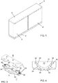
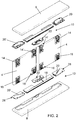
- the device according to the invention applicable to a wardrobe structure 2 comprising two doors 4, 4', slidable within the space bounded by a top 6 and a bottom 8 comprises two guides, an upper guide 10 to be incorporated into the top 6, and a lower guide 12 to be incorporated into the bottom 8, both at a short distance from the front edge of the top and bottom.
- the device also comprises two pairs of carriages for each door 4, 4' and more precisely an outer upper carriage 14, an inner upper carriage 14', an outer lower carriage 16, and an inner lower carriage 16'.
- Each guide 10, 12 is provided with a single rectilinear track 18 extending parallel to the guide and also to the front edge of the panel (top 6 or bottom 8) to which it is applied, and terminating with a forwardly inclined portion 20, 20'.
- a type of double changeover switch 22 is applied, consisting of a block 23 formed in two parts to be vertically coupled together. It comprises internally a short rectilinear branch 24 creating continuity with the track rectilinear portion 18, and two deviating branches 26, 26', which extend symmetrically from the rectilinear branch 24 and have an inclination preferably greater than the inclination of the inclined portions 20, 20' of the two guides 10, 12.
- each guide 10, 12 comprises, in addition to the double changeover switch 22, a profile portion in which the rectilinear portion 18 is formed, and two endpieces 28, 28', in each of which the inclined portion 20, 20' is formed.
- the length of the guide 10, 12 can be adapted to the length of the wardrobe, by using a profile piece which is cut to size and to which the two endpieces 28, 28' and the central double changeover switch 22 are applied.
- a type of tongue 30, 30' is provided in the manner of railway switches, which is hinged to the block 23 of the double changeover switch 22 and is associated with a spring 32, 32' which tends to maintain the tongue in a deviated position in the absence of external stresses.
- the tongue 30, 30' is also provided at the opposite end to the deviating portion with an appendix 34, 34', which overruns the end portion of the deviated branch 26, 26' of the switch when the tongue 30, 30' is in the deviated position, whereas it leaves the deviated branch 26, 26' free when the tongue 30, 30' is in the non-deviated position.
- carriages 14, 14', 16, 16' which are mounted on each door 4, 4'.
- these comprise two lower carriages 16, 16' mounted close to the two lower corners of each of the two doors 4, 4', and two carriages 14, 14' mounted close to the two upper corners of said doors.
- the carriages 14, 14', 16, 16' are substantially identical and comprise a body 36 for fixing to the door 4, 4', and a pin 38, 38' and 40, 40', which engages the upper guide 10 and the lower guide 12 respectively.
- each lower carriage 16, 16' is also provided with a wheel 42, preferably rubber coated, which has its axis perpendicular to the plane of the door 4, 4' and rests on the lower guide 12.
- both the upper pin 38, 38' and the lower wheel 42 can be adjusted vertically relative to the carriage body 36, for the reasons which will be apparent hereinafter, but for production standardization reasons it is advantageous for the body 36 of all carriages 14, 14', 16, 16' to be provided with a slide 44 provided with a vertical pin, with which a threaded adjustment knob 46 is associated.
- the relative upper pin 38, 38' is fixed to the slide 44 of each upper carriage 14, 14', while the relative upper pin 40, 40' and a wheel 42 are fixed to the slide 44 of each lower carriage 16, 16'.
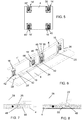
- each closing door 4, 4' In order to damp the travel of each closing door 4, 4' while at the same time ensuring stability of the door when in the closed position, it can be advantageous to insert a magnet 48 ( Figures 7, 8 ) into each endpiece 28, 28' of each guide 10, 12, and to embed a magnet 50 into the upper horizontal edge and into lower horizontal edge of each door 4, 4'.
- the position of the magnets 48, 50 is such that when the door 4, 4' is closed the magnets 50 embedded into them are slightly closer to the outer sides of the wardrobe than the magnets 48 inserted into the endpieces 28, 28'; moreover the polarity of corresponding magnets is equal, meaning that the magnets are antagonistic and tend to repel each other.
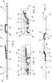
- the outer upper carriage 14 of the left door 4 engages via its pin 38 the end of the left inclined portion 20 of the upper guide 10, whereas the inner upper carriage 14' of the said door 4 engages via its pin 38' the left deviated branch 26 of the upper double changeover switch 22.
- This handle is not shown on the drawings for simplicity, but can be of traditional recessed type and be applied close to the outer vertical edge of said door, or be of projecting type and be applied along the edge itself.
- the tangential push against the door 4 causes it to move towards the right with a smooth movement, due to the resting of the door on the lower guide 12 via the two wheels 42, which because of the low rolling friction enables doors even of large dimensions and considerable weight to be formed.
- the initial part of the sliding of the door 4 involves its movement towards the right and, by virtue of the presence of the inclined portion 20 and the inclined branches 26 of the two changeover switches 22, and the greater inclination of each inclined branch 26 than the corresponding inclined portion 20, also involves a roto-translation of the door itself, which becomes set in a plane inward of and parallel to the plane of this door, to then slide along the rectilinear portion 18 of the guide 10, 12 behind the door 4'.
- a stop applied to the fixed structure of the wardrobe 2 but not shown in the drawings halts the travel of the door 4 an instant before the pins 38, 40 and 38', 40' of its upper carriages 14, 14', and lower carriages 16, 16' enter the inclined portions 20', 26', as this would cause an outward displacement of the door 4, hindered however by presence of the door 4'.
- the dimensions of the parts are such that when the door 4 is at the end of its opening travel, the pins 38, 40 of its upper outer carriage 14 and lower outer carriage 16 have not reached the tongue 30 of the changeover switches 22, this meaning that when the door is to be returned to its closed position, i.e. when the user effects the opposite manoeuvre to the preceding by moving the door towards the left, the pins 38', 40' of the inner carriages 14', 16' do not enter the deviated branch 26 of the changeover switches 22, given the arrangement of the respective tongues 30.
- the corresponding magnets 48, 50 tend to repel each other to determine a braking effect on the door travel; however when the door has overcome the repelling force between the magnets 48, 50 by inertia, i.e. when the magnets 50 have passed to the opposite side of the magnets 48, the repelling force exerted thereby tends to maintain the door 4 in the closed position until it is voluntarily pushed by the operator in the direction which causes the wardrobe to open.
- the aforedescribed device is much more advantageous than traditional devices, and in particular:
- the aforedescribed device is applicable to wardrobes with two doors 4, 4'; however the market also requires three-door wardrobes, for which the present invention also comprises a useful accessory which integrates the aforedescribed device and makes it usable in a three-door wardrobe, in which the third door 4" involves certain problems not present in a two door wardrobe.
- the presence of the third door 4" which is a terminal door, makes it necessary to prevent it from being able to be moved when the central door 4 is open, in that if said third door 4" could be opened, it could hinder closure of the central door 4.
- the two guides 10, 12 then proceed beyond the changeover switch 62 by a rectilinear part 68, which extends the portion 18, but with interruption, and terminates at the guide end with an inclined portion 20" totally similar to the inclined portion 20 of the preceding version of the two-door wardrobe.
- the changeover switch 62 comprises a tongue 30" which presents, similarly to the tongues 30, 30', an appendix 34", which overruns the terminal portion of the deviated branch 64 when the tongue is in the deviated position, whereas it leaves it free when in the non-deviated position.
- the tongue 30" also comprises an appendix 70 which engages in an inclined slot 72 provided at the end of a latch 74 movable parallel to the rectilinear portion 18 of the guide track. This engagement means that when the tongue 30" is in the deviated position, the latch 74 partly overruns the curved end of the non-deviated branch 66 of the changeover switch 62, while when in the non-deviated position it leaves the non-deviated branch completely free.
- This embodiment of the device operates as follows: if the user wishes to open the central doors 4, the user acts as in the already described case. However in this case the initial part of the movement of the central door 4 brings the tongue 30" into the deviated position and consequently causes the latch 74 to overrun the non-deviated branch 66 of the changeover switch 62 and to block the pin 40" of the door 4", which in this manner becomes locked in the closed position until the central door 4 returns to the closed position.
- the operation can be carried out without any obstacle, as the branch 66 of the changeover switch 62 is free; then when the door 4" has been brought into the open position, it is its own presence which prevents any attempt to open the central door 4.
- this embodiment also offers the further advantage of enabling wardrobes with three slidable doors to be produced.
Landscapes
- Engineering & Computer Science (AREA)
- Mechanical Engineering (AREA)
- Wing Frames And Configurations (AREA)
- Support Devices For Sliding Doors (AREA)
Priority Applications (1)
| Application Number | Priority Date | Filing Date | Title |
|---|---|---|---|
| PL15790679T PL3209840T3 (pl) | 2014-10-20 | 2015-10-19 | Urządzenie prowadzące do pary drzwi przesuwnych pojemnika, zwłaszcza garderoby |
Applications Claiming Priority (2)
| Application Number | Priority Date | Filing Date | Title |
|---|---|---|---|
| ITVE20140057 | 2014-10-20 | ||
| PCT/IB2015/058027 WO2016063195A1 (en) | 2014-10-20 | 2015-10-19 | Guide device for a pair of slidable doors of a container, particularly of a wardrobe |
Publications (2)
| Publication Number | Publication Date |
|---|---|
| EP3209840A1 EP3209840A1 (en) | 2017-08-30 |
| EP3209840B1 true EP3209840B1 (en) | 2019-11-06 |
Family
ID=52101531
Family Applications (1)
| Application Number | Title | Priority Date | Filing Date |
|---|---|---|---|
| EP15790679.3A Active EP3209840B1 (en) | 2014-10-20 | 2015-10-19 | Guide device for a pair of slidable doors of a container, particularly of a wardrobe |
Country Status (4)
| Country | Link |
|---|---|
| EP (1) | EP3209840B1 (pl) |
| ES (1) | ES2768755T3 (pl) |
| PL (1) | PL3209840T3 (pl) |
| WO (1) | WO2016063195A1 (pl) |
Families Citing this family (2)
| Publication number | Priority date | Publication date | Assignee | Title |
|---|---|---|---|---|
| IT201800009415A1 (it) * | 2018-10-12 | 2020-04-12 | Si Srl | Dispositivo di guida di una coppia di ante scorrevoli di un contenitore, particolarmente di un armadio. |
| US11864669B2 (en) * | 2020-11-25 | 2024-01-09 | Hussmann Corporation | Merchandiser including track door system |
Family Cites Families (4)
| Publication number | Priority date | Publication date | Assignee | Title |
|---|---|---|---|---|
| GB871745A (en) * | 1958-09-10 | 1961-06-28 | Reginald Henry Procter | Sliding closure or door means |
| DE1554401A1 (de) * | 1965-01-29 | 1970-04-02 | Heinz Racherbaeumer | Schiebetuer fuer Moebel,Ladeninneneinrichtungen u.dgl. |
| ITTO20030109A1 (it) * | 2003-02-14 | 2004-08-15 | Poli Pietro De | Sistema di scorrimento per telai, pannelli e simili, quali sportelli di porte, finestre e mobili |
| US8113607B2 (en) | 2009-05-08 | 2012-02-14 | Steelcase Inc. | Storage assembly |
-
2015
- 2015-10-19 PL PL15790679T patent/PL3209840T3/pl unknown
- 2015-10-19 EP EP15790679.3A patent/EP3209840B1/en active Active
- 2015-10-19 ES ES15790679T patent/ES2768755T3/es active Active
- 2015-10-19 WO PCT/IB2015/058027 patent/WO2016063195A1/en not_active Ceased
Non-Patent Citations (1)
| Title |
|---|
| None * |
Also Published As
| Publication number | Publication date |
|---|---|
| EP3209840A1 (en) | 2017-08-30 |
| ES2768755T3 (es) | 2020-06-23 |
| PL3209840T3 (pl) | 2020-05-18 |
| WO2016063195A1 (en) | 2016-04-28 |
Similar Documents
| Publication | Publication Date | Title |
|---|---|---|
| US11492833B2 (en) | Guide system for guiding a door leaf | |
| US11098512B2 (en) | Guide system for guiding a furniture door | |
| US8939525B1 (en) | Self-closing buffer and automatic rebound mechanism for slide rail | |
| US20180087305A1 (en) | Ejection device for a movable furniture part | |
| JP6815018B2 (ja) | 摺動ドアのためのガイドデバイス | |
| US20170051813A1 (en) | Device for moving a furniture part, and item of furniture | |
| US7708358B2 (en) | Furniture item having at least a first and a second furniture portion | |
| US9211007B2 (en) | Drive device for a movable furniture part | |
| EP1293629A2 (en) | Cabinet latch | |
| CN104797770B (zh) | 推拉式门的开关装置 | |
| US9968193B1 (en) | Slide rail assembly with switch | |
| EP3864244B1 (en) | A guiding device for sliding doors | |
| US12312835B2 (en) | Self-adjusting locking piece for a locking unit | |
| TW201715998A (zh) | 驅動機構 | |
| MY175589A (en) | Drive device for a moveable furniture part | |
| CN104095421A (zh) | 用于工具箱中的一系列抽屉的倾斜防止组件 | |
| US20130199099A1 (en) | Sliding door arrangement | |
| US20190145127A1 (en) | Push and Slide Gate Handle | |
| US20070039972A1 (en) | Hinge, in particular for connecting two flap portions of a folding flap | |
| CN104854292A (zh) | 滑动门的导向组件、滑动门以及家具 | |
| WO2016063195A1 (en) | Guide device for a pair of slidable doors of a container, particularly of a wardrobe | |
| KR20060015537A (ko) | 파티션 | |
| KR101654917B1 (ko) | 가구용 슬라이딩 도어의 엔드 완충장치 | |
| KR200477983Y1 (ko) | 욕실용 수납장 | |
| KR101623044B1 (ko) | 슬라이딩 도어의 반자동 개폐장치 |
Legal Events
| Date | Code | Title | Description |
|---|---|---|---|
| STAA | Information on the status of an ep patent application or granted ep patent |
Free format text: STATUS: THE INTERNATIONAL PUBLICATION HAS BEEN MADE |
|
| PUAI | Public reference made under article 153(3) epc to a published international application that has entered the european phase |
Free format text: ORIGINAL CODE: 0009012 |
|
| STAA | Information on the status of an ep patent application or granted ep patent |
Free format text: STATUS: REQUEST FOR EXAMINATION WAS MADE |
|
| 17P | Request for examination filed |
Effective date: 20170516 |
|
| AK | Designated contracting states |
Kind code of ref document: A1 Designated state(s): AL AT BE BG CH CY CZ DE DK EE ES FI FR GB GR HR HU IE IS IT LI LT LU LV MC MK MT NL NO PL PT RO RS SE SI SK SM TR |
|
| AX | Request for extension of the european patent |
Extension state: BA ME |
|
| DAV | Request for validation of the european patent (deleted) | ||
| DAX | Request for extension of the european patent (deleted) | ||
| GRAP | Despatch of communication of intention to grant a patent |
Free format text: ORIGINAL CODE: EPIDOSNIGR1 |
|
| STAA | Information on the status of an ep patent application or granted ep patent |
Free format text: STATUS: GRANT OF PATENT IS INTENDED |
|
| INTG | Intention to grant announced |
Effective date: 20190826 |
|
| GRAS | Grant fee paid |
Free format text: ORIGINAL CODE: EPIDOSNIGR3 |
|
| GRAA | (expected) grant |
Free format text: ORIGINAL CODE: 0009210 |
|
| STAA | Information on the status of an ep patent application or granted ep patent |
Free format text: STATUS: THE PATENT HAS BEEN GRANTED |
|
| AK | Designated contracting states |
Kind code of ref document: B1 Designated state(s): AL AT BE BG CH CY CZ DE DK EE ES FI FR GB GR HR HU IE IS IT LI LT LU LV MC MK MT NL NO PL PT RO RS SE SI SK SM TR |
|
| REG | Reference to a national code |
Ref country code: GB Ref legal event code: FG4D |
|
| REG | Reference to a national code |
Ref country code: CH Ref legal event code: EP Ref country code: AT Ref legal event code: REF Ref document number: 1198940 Country of ref document: AT Kind code of ref document: T Effective date: 20191115 |
|
| REG | Reference to a national code |
Ref country code: IE Ref legal event code: FG4D |
|
| REG | Reference to a national code |
Ref country code: DE Ref legal event code: R096 Ref document number: 602015041257 Country of ref document: DE |
|
| REG | Reference to a national code |
Ref country code: NL Ref legal event code: MP Effective date: 20191106 |
|
| REG | Reference to a national code |
Ref country code: LT Ref legal event code: MG4D |
|
| PG25 | Lapsed in a contracting state [announced via postgrant information from national office to epo] |
Ref country code: PT Free format text: LAPSE BECAUSE OF FAILURE TO SUBMIT A TRANSLATION OF THE DESCRIPTION OR TO PAY THE FEE WITHIN THE PRESCRIBED TIME-LIMIT Effective date: 20200306 Ref country code: NO Free format text: LAPSE BECAUSE OF FAILURE TO SUBMIT A TRANSLATION OF THE DESCRIPTION OR TO PAY THE FEE WITHIN THE PRESCRIBED TIME-LIMIT Effective date: 20200206 Ref country code: LV Free format text: LAPSE BECAUSE OF FAILURE TO SUBMIT A TRANSLATION OF THE DESCRIPTION OR TO PAY THE FEE WITHIN THE PRESCRIBED TIME-LIMIT Effective date: 20191106 Ref country code: SE Free format text: LAPSE BECAUSE OF FAILURE TO SUBMIT A TRANSLATION OF THE DESCRIPTION OR TO PAY THE FEE WITHIN THE PRESCRIBED TIME-LIMIT Effective date: 20191106 Ref country code: FI Free format text: LAPSE BECAUSE OF FAILURE TO SUBMIT A TRANSLATION OF THE DESCRIPTION OR TO PAY THE FEE WITHIN THE PRESCRIBED TIME-LIMIT Effective date: 20191106 Ref country code: BG Free format text: LAPSE BECAUSE OF FAILURE TO SUBMIT A TRANSLATION OF THE DESCRIPTION OR TO PAY THE FEE WITHIN THE PRESCRIBED TIME-LIMIT Effective date: 20200206 Ref country code: GR Free format text: LAPSE BECAUSE OF FAILURE TO SUBMIT A TRANSLATION OF THE DESCRIPTION OR TO PAY THE FEE WITHIN THE PRESCRIBED TIME-LIMIT Effective date: 20200207 Ref country code: LT Free format text: LAPSE BECAUSE OF FAILURE TO SUBMIT A TRANSLATION OF THE DESCRIPTION OR TO PAY THE FEE WITHIN THE PRESCRIBED TIME-LIMIT Effective date: 20191106 Ref country code: NL Free format text: LAPSE BECAUSE OF FAILURE TO SUBMIT A TRANSLATION OF THE DESCRIPTION OR TO PAY THE FEE WITHIN THE PRESCRIBED TIME-LIMIT Effective date: 20191106 |
|
| PG25 | Lapsed in a contracting state [announced via postgrant information from national office to epo] |
Ref country code: IS Free format text: LAPSE BECAUSE OF FAILURE TO SUBMIT A TRANSLATION OF THE DESCRIPTION OR TO PAY THE FEE WITHIN THE PRESCRIBED TIME-LIMIT Effective date: 20200306 Ref country code: RS Free format text: LAPSE BECAUSE OF FAILURE TO SUBMIT A TRANSLATION OF THE DESCRIPTION OR TO PAY THE FEE WITHIN THE PRESCRIBED TIME-LIMIT Effective date: 20191106 Ref country code: HR Free format text: LAPSE BECAUSE OF FAILURE TO SUBMIT A TRANSLATION OF THE DESCRIPTION OR TO PAY THE FEE WITHIN THE PRESCRIBED TIME-LIMIT Effective date: 20191106 |
|
| REG | Reference to a national code |
Ref country code: ES Ref legal event code: FG2A Ref document number: 2768755 Country of ref document: ES Kind code of ref document: T3 Effective date: 20200623 |
|
| PG25 | Lapsed in a contracting state [announced via postgrant information from national office to epo] |
Ref country code: AL Free format text: LAPSE BECAUSE OF FAILURE TO SUBMIT A TRANSLATION OF THE DESCRIPTION OR TO PAY THE FEE WITHIN THE PRESCRIBED TIME-LIMIT Effective date: 20191106 |
|
| PG25 | Lapsed in a contracting state [announced via postgrant information from national office to epo] |
Ref country code: RO Free format text: LAPSE BECAUSE OF FAILURE TO SUBMIT A TRANSLATION OF THE DESCRIPTION OR TO PAY THE FEE WITHIN THE PRESCRIBED TIME-LIMIT Effective date: 20191106 Ref country code: CZ Free format text: LAPSE BECAUSE OF FAILURE TO SUBMIT A TRANSLATION OF THE DESCRIPTION OR TO PAY THE FEE WITHIN THE PRESCRIBED TIME-LIMIT Effective date: 20191106 Ref country code: EE Free format text: LAPSE BECAUSE OF FAILURE TO SUBMIT A TRANSLATION OF THE DESCRIPTION OR TO PAY THE FEE WITHIN THE PRESCRIBED TIME-LIMIT Effective date: 20191106 Ref country code: DK Free format text: LAPSE BECAUSE OF FAILURE TO SUBMIT A TRANSLATION OF THE DESCRIPTION OR TO PAY THE FEE WITHIN THE PRESCRIBED TIME-LIMIT Effective date: 20191106 |
|
| REG | Reference to a national code |
Ref country code: DE Ref legal event code: R097 Ref document number: 602015041257 Country of ref document: DE |
|
| PG25 | Lapsed in a contracting state [announced via postgrant information from national office to epo] |
Ref country code: SK Free format text: LAPSE BECAUSE OF FAILURE TO SUBMIT A TRANSLATION OF THE DESCRIPTION OR TO PAY THE FEE WITHIN THE PRESCRIBED TIME-LIMIT Effective date: 20191106 Ref country code: SM Free format text: LAPSE BECAUSE OF FAILURE TO SUBMIT A TRANSLATION OF THE DESCRIPTION OR TO PAY THE FEE WITHIN THE PRESCRIBED TIME-LIMIT Effective date: 20191106 |
|
| PLBE | No opposition filed within time limit |
Free format text: ORIGINAL CODE: 0009261 |
|
| STAA | Information on the status of an ep patent application or granted ep patent |
Free format text: STATUS: NO OPPOSITION FILED WITHIN TIME LIMIT |
|
| 26N | No opposition filed |
Effective date: 20200807 |
|
| PG25 | Lapsed in a contracting state [announced via postgrant information from national office to epo] |
Ref country code: SI Free format text: LAPSE BECAUSE OF FAILURE TO SUBMIT A TRANSLATION OF THE DESCRIPTION OR TO PAY THE FEE WITHIN THE PRESCRIBED TIME-LIMIT Effective date: 20191106 |
|
| GBPC | Gb: european patent ceased through non-payment of renewal fee |
Effective date: 20201019 |
|
| PG25 | Lapsed in a contracting state [announced via postgrant information from national office to epo] |
Ref country code: MC Free format text: LAPSE BECAUSE OF FAILURE TO SUBMIT A TRANSLATION OF THE DESCRIPTION OR TO PAY THE FEE WITHIN THE PRESCRIBED TIME-LIMIT Effective date: 20191106 Ref country code: LU Free format text: LAPSE BECAUSE OF NON-PAYMENT OF DUE FEES Effective date: 20201019 |
|
| REG | Reference to a national code |
Ref country code: BE Ref legal event code: MM Effective date: 20201031 |
|
| PG25 | Lapsed in a contracting state [announced via postgrant information from national office to epo] |
Ref country code: FR Free format text: LAPSE BECAUSE OF NON-PAYMENT OF DUE FEES Effective date: 20201031 |
|
| PG25 | Lapsed in a contracting state [announced via postgrant information from national office to epo] |
Ref country code: BE Free format text: LAPSE BECAUSE OF NON-PAYMENT OF DUE FEES Effective date: 20201031 Ref country code: GB Free format text: LAPSE BECAUSE OF NON-PAYMENT OF DUE FEES Effective date: 20201019 |
|
| PG25 | Lapsed in a contracting state [announced via postgrant information from national office to epo] |
Ref country code: IE Free format text: LAPSE BECAUSE OF NON-PAYMENT OF DUE FEES Effective date: 20201019 |
|
| REG | Reference to a national code |
Ref country code: AT Ref legal event code: UEP Ref document number: 1198940 Country of ref document: AT Kind code of ref document: T Effective date: 20191106 |
|
| PGFP | Annual fee paid to national office [announced via postgrant information from national office to epo] |
Ref country code: ES Payment date: 20211228 Year of fee payment: 7 |
|
| PG25 | Lapsed in a contracting state [announced via postgrant information from national office to epo] |
Ref country code: TR Free format text: LAPSE BECAUSE OF FAILURE TO SUBMIT A TRANSLATION OF THE DESCRIPTION OR TO PAY THE FEE WITHIN THE PRESCRIBED TIME-LIMIT Effective date: 20191106 Ref country code: MT Free format text: LAPSE BECAUSE OF FAILURE TO SUBMIT A TRANSLATION OF THE DESCRIPTION OR TO PAY THE FEE WITHIN THE PRESCRIBED TIME-LIMIT Effective date: 20191106 Ref country code: CY Free format text: LAPSE BECAUSE OF FAILURE TO SUBMIT A TRANSLATION OF THE DESCRIPTION OR TO PAY THE FEE WITHIN THE PRESCRIBED TIME-LIMIT Effective date: 20191106 |
|
| PG25 | Lapsed in a contracting state [announced via postgrant information from national office to epo] |
Ref country code: MK Free format text: LAPSE BECAUSE OF FAILURE TO SUBMIT A TRANSLATION OF THE DESCRIPTION OR TO PAY THE FEE WITHIN THE PRESCRIBED TIME-LIMIT Effective date: 20191106 |
|
| PGFP | Annual fee paid to national office [announced via postgrant information from national office to epo] |
Ref country code: PL Payment date: 20220926 Year of fee payment: 8 |
|
| PGFP | Annual fee paid to national office [announced via postgrant information from national office to epo] |
Ref country code: AT Payment date: 20220927 Year of fee payment: 8 |
|
| P01 | Opt-out of the competence of the unified patent court (upc) registered |
Effective date: 20230519 |
|
| REG | Reference to a national code |
Ref country code: ES Ref legal event code: FD2A Effective date: 20231129 |
|
| PG25 | Lapsed in a contracting state [announced via postgrant information from national office to epo] |
Ref country code: ES Free format text: LAPSE BECAUSE OF NON-PAYMENT OF DUE FEES Effective date: 20221020 |
|
| PG25 | Lapsed in a contracting state [announced via postgrant information from national office to epo] |
Ref country code: ES Free format text: LAPSE BECAUSE OF NON-PAYMENT OF DUE FEES Effective date: 20221020 |
|
| PGFP | Annual fee paid to national office [announced via postgrant information from national office to epo] |
Ref country code: DE Payment date: 20230927 Year of fee payment: 9 Ref country code: CH Payment date: 20231102 Year of fee payment: 9 |
|
| REG | Reference to a national code |
Ref country code: AT Ref legal event code: MM01 Ref document number: 1198940 Country of ref document: AT Kind code of ref document: T Effective date: 20231019 |
|
| PG25 | Lapsed in a contracting state [announced via postgrant information from national office to epo] |
Ref country code: AT Free format text: LAPSE BECAUSE OF NON-PAYMENT OF DUE FEES Effective date: 20231019 |
|
| PG25 | Lapsed in a contracting state [announced via postgrant information from national office to epo] |
Ref country code: AT Free format text: LAPSE BECAUSE OF NON-PAYMENT OF DUE FEES Effective date: 20231019 |
|
| PG25 | Lapsed in a contracting state [announced via postgrant information from national office to epo] |
Ref country code: PL Free format text: LAPSE BECAUSE OF NON-PAYMENT OF DUE FEES Effective date: 20231019 |
|
| REG | Reference to a national code |
Ref country code: DE Ref legal event code: R119 Ref document number: 602015041257 Country of ref document: DE |
|
| REG | Reference to a national code |
Ref country code: CH Ref legal event code: PL |
|
| PG25 | Lapsed in a contracting state [announced via postgrant information from national office to epo] |
Ref country code: DE Free format text: LAPSE BECAUSE OF NON-PAYMENT OF DUE FEES Effective date: 20250501 |
|
| PG25 | Lapsed in a contracting state [announced via postgrant information from national office to epo] |
Ref country code: CH Free format text: LAPSE BECAUSE OF NON-PAYMENT OF DUE FEES Effective date: 20241031 |
|
| PGFP | Annual fee paid to national office [announced via postgrant information from national office to epo] |
Ref country code: IT Payment date: 20251024 Year of fee payment: 11 |