EP3209543B1 - Verstellbares reibringgetriebe für ein mit motorkraft und/oder pedalkraft betreibbares fahrzeug - Google Patents
Verstellbares reibringgetriebe für ein mit motorkraft und/oder pedalkraft betreibbares fahrzeug Download PDFInfo
- Publication number
- EP3209543B1 EP3209543B1 EP15763335.5A EP15763335A EP3209543B1 EP 3209543 B1 EP3209543 B1 EP 3209543B1 EP 15763335 A EP15763335 A EP 15763335A EP 3209543 B1 EP3209543 B1 EP 3209543B1
- Authority
- EP
- European Patent Office
- Prior art keywords
- friction ring
- type transmission
- friction
- transmission
- gear
- Prior art date
- Legal status (The legal status is an assumption and is not a legal conclusion. Google has not performed a legal analysis and makes no representation as to the accuracy of the status listed.)
- Active
Links
Images


Classifications
-
- B—PERFORMING OPERATIONS; TRANSPORTING
- B62—LAND VEHICLES FOR TRAVELLING OTHERWISE THAN ON RAILS
- B62M—RIDER PROPULSION OF WHEELED VEHICLES OR SLEDGES; POWERED PROPULSION OF SLEDGES OR SINGLE-TRACK CYCLES; TRANSMISSIONS SPECIALLY ADAPTED FOR SUCH VEHICLES
- B62M11/00—Transmissions characterised by the use of interengaging toothed wheels or frictionally-engaging wheels
- B62M11/04—Transmissions characterised by the use of interengaging toothed wheels or frictionally-engaging wheels of changeable ratio
- B62M11/14—Transmissions characterised by the use of interengaging toothed wheels or frictionally-engaging wheels of changeable ratio with planetary gears
- B62M11/145—Transmissions characterised by the use of interengaging toothed wheels or frictionally-engaging wheels of changeable ratio with planetary gears built in, or adjacent to, the bottom bracket
-
- B—PERFORMING OPERATIONS; TRANSPORTING
- B62—LAND VEHICLES FOR TRAVELLING OTHERWISE THAN ON RAILS
- B62M—RIDER PROPULSION OF WHEELED VEHICLES OR SLEDGES; POWERED PROPULSION OF SLEDGES OR SINGLE-TRACK CYCLES; TRANSMISSIONS SPECIALLY ADAPTED FOR SUCH VEHICLES
- B62M6/00—Rider propulsion of wheeled vehicles with additional source of power, e.g. combustion engine or electric motor
- B62M6/40—Rider propelled cycles with auxiliary electric motor
- B62M6/55—Rider propelled cycles with auxiliary electric motor power-driven at crank shafts parts
-
- B—PERFORMING OPERATIONS; TRANSPORTING
- B62—LAND VEHICLES FOR TRAVELLING OTHERWISE THAN ON RAILS
- B62M—RIDER PROPULSION OF WHEELED VEHICLES OR SLEDGES; POWERED PROPULSION OF SLEDGES OR SINGLE-TRACK CYCLES; TRANSMISSIONS SPECIALLY ADAPTED FOR SUCH VEHICLES
- B62M11/00—Transmissions characterised by the use of interengaging toothed wheels or frictionally-engaging wheels
- B62M11/04—Transmissions characterised by the use of interengaging toothed wheels or frictionally-engaging wheels of changeable ratio
- B62M11/12—Transmissions characterised by the use of interengaging toothed wheels or frictionally-engaging wheels of changeable ratio with frictionally-engaging wheels
-
- F—MECHANICAL ENGINEERING; LIGHTING; HEATING; WEAPONS; BLASTING
- F16—ENGINEERING ELEMENTS AND UNITS; GENERAL MEASURES FOR PRODUCING AND MAINTAINING EFFECTIVE FUNCTIONING OF MACHINES OR INSTALLATIONS; THERMAL INSULATION IN GENERAL
- F16H—GEARING
- F16H15/00—Gearings for conveying rotary motion with variable gear ratio, or for reversing rotary motion, by friction between rotary members
- F16H15/48—Gearings for conveying rotary motion with variable gear ratio, or for reversing rotary motion, by friction between rotary members with members having orbital motion
- F16H15/50—Gearings providing a continuous range of gear ratios
- F16H15/52—Gearings providing a continuous range of gear ratios in which a member of uniform effective diameter mounted on a shaft may co-operate with different parts of another member
-
- F—MECHANICAL ENGINEERING; LIGHTING; HEATING; WEAPONS; BLASTING
- F16—ENGINEERING ELEMENTS AND UNITS; GENERAL MEASURES FOR PRODUCING AND MAINTAINING EFFECTIVE FUNCTIONING OF MACHINES OR INSTALLATIONS; THERMAL INSULATION IN GENERAL
- F16H—GEARING
- F16H37/00—Combinations of mechanical gearings, not provided for in groups F16H1/00 - F16H35/00
- F16H37/02—Combinations of mechanical gearings, not provided for in groups F16H1/00 - F16H35/00 comprising essentially only toothed or friction gearings
- F16H37/021—Combinations of mechanical gearings, not provided for in groups F16H1/00 - F16H35/00 comprising essentially only toothed or friction gearings toothed gearing combined with continuously variable friction gearing
- F16H37/022—Combinations of mechanical gearings, not provided for in groups F16H1/00 - F16H35/00 comprising essentially only toothed or friction gearings toothed gearing combined with continuously variable friction gearing the toothed gearing having orbital motion
Definitions
- the present invention relates to a friction ring gear for a motor and / or pedal force operable vehicle with crankshaft crankshaft and crankshaft center axis, which is to be understood as a theoretical rather than a fixed physical axis, the friction ring gear can be used in particular in an electric bicycle.
- the friction-ring transmission has an inner friction ring and an outer friction ring and at least one rotatable double-cone pulley frictionally engaged with the inner and outer friction rings.
- Friction-ring transmissions have the advantages that they are infinitely variable and also in the state adjustable.
- a disadvantage of one Friction-ring transmission is the comparatively poor efficiency caused by both rubbing and transmission components such as bearings.
- a disadvantage of the construction of the friction ring according to the DE 10 2012 209 096 A1 is that the force return device, which allows the friction rings to be pressed against the double cones, runs around the outside of the friction-ring transmission. As a result, the force feedback device is a part with a large surface and therefore heavy, which speaks against the generally valid for vehicles lightweight construction.
- a disadvantage of the known transmissions is further that the adjustment of the transmission ratio is performed exclusively by the interior of the drive or output shaft of the friction ring and as adjustment by thread. This significantly hinders the design freedom in the integration of such a transmission in a vehicle; In particular, a rotation of a few turns must be generated to adjust. In addition, this rotational movement is locally fixed to a center position with respect to the transmission. The axis of rotation of the Verstellrotation is fixed and runs coaxially to the central axis of the transmission.
- the friction ring gear according to the invention with the features of claim 1 has an adjusting device for the transmission ratio of the friction ring, which is movable along an adjustment path.
- the Adjustment path has a component of its course in the direction of a central axis of the roller carrier, while at the same time at most less than a complete revolution extends around the friction ring gear, preferably less than 180 degrees, more preferably less than 90 degrees.
- the adjustment path is straight and follows the direction of an imaginary central axis of the friction-bearing transmission. This central axis usually coincides with the central axis of a roller carrier of the double cone rollers.
- the adjusting device penetrates a housing surrounding the friction ring gear.
- the adjustment path according to the invention runs along a recess in the housing.
- the adjustment path is less than 360 degrees, preferably less than 180 degrees, more preferably less than 90 degrees.
- the housing can then be made in one piece in particular, which is generally less expensive than a multi-piece composite solution. Special strength of the housing is achieved when at least half a revolution of the housing is not broken by the adjustment. Less than 90 degrees of circulation of the adjustment path to the friction-ring transmission has the advantage that the adjustment is simplified by the lower Umlenkswinkel. A particularly simple adjustment results in a purely linear movement substantially in the direction of the central axis of the roller carrier.
- the adjusting device is firmly connected to the roller carrier, ie, it is not movable to this, so that an actuation of the adjusting device directly displaces the roller carrier in the axial direction, whereby the translation of the friction-belt transmission is changed.
- the roller carrier is rotated during adjustment, but preferably the roller carrier is not rotated and moved only linear.
- the adjusting device has no adjustment thread.
- the adjusting device preferably does not run through the center of the friction ring gear. The adjusting device according to the invention makes it possible to quickly and easily set the ratio of the friction-ring transmission.
- the inner and outer friction rings extend around the crankshaft. This makes it possible to arrange the crankshaft in the center of the friction ring gear.
- the friction-ring gear is filled with a traction fluid, which has good lubricating properties and still causes high friction between the friction partners in intensive frictional contact.
- a friction ring transmission with the adjustment according to the invention is particularly preferably installed on the bottom bracket. Also preferred is an integrated design with the bottom bracket and the engine. This results in the advantages of an optimal mass distribution, which is achieved by a deep, central center of gravity and a light rear wheel. This results in improved handling, lower suspension masses and good driving dynamics. In addition, the assembly and disassembly of the rear wheel is simplified.
- the bicycle manufacturer also needs to install only a single integrated drive unit instead of several separate components in the bicycle. The customer can be presented with a unified module of translation and drive control.
- the force feedback device extends within the friction rings. In this way, weight is saved in comparison to the force feedback device running according to the prior art outside the friction rings.
- at least a portion of the force feedback device extends in the direction of the central axis of the roller carrier. In particular, this section has a smaller diameter than the friction diameter of the inner friction ring. It is particularly advantageous that the internally encircling according to this embodiment force return device allows the course of the adjustment of the friction ring to a breakthrough in the housing. According to the prior art, this required space between the roll holder and the housing is already occupied by the circumferential force return device.
- the roller carrier and the housing of the friction ring gear are rotatably connected to each other.
- the roller carrier can be moved relative to the friction wheels.
- the friction wheels are designed to be rotatable, but preferably in their position relative to the Housing fixed to this rotation.
- the adjusting device can be firmly connected to the roller carrier. It can be designed as a movable arm, which extends in particular from the roller carrier to outside the transmission. In this case, the boom preferably passes through the housing.
- the vehicle is equipped with a servomotor with which the adjusting device is adjustable.
- the servomotor may be arranged on the friction-ring transmission and / or arranged in an integrated unit of engine, transmission and crankshaft.
- the friction-ring transmission comprises two expansion clutches, which spread open under load and increase the contact pressure between the friction rings and the double-cone rollers.
- the Sp Schwarzkupplonne is preferably associated with each one of the friction rings.
- the Sp Schwarzkupplonne are annular, wherein the force return flow path extends at least through one of the Sp Schwarzkupplonne.
- the force feedback device is arranged around the crankshaft for the pedal cranks of the vehicle.
- the force feedback device is designed essentially as a sleeve, wherein the latter has a section extending axially along the crankshaft and a section extending radially in the direction of at least one of the friction rings.
- This embodiment is lightweight and also simple in construction and therefore easy to manufacture.
- the radially extending portion may be made separate from the axially extending portion and then joined together to form a one-piece or a composite sleeve thereafter.
- the internal force feedback device is rotatably configured with respect to the crankshaft. In this way, the speed of a non-rotatably connected to the force feedback device friction ring is dependent on the speed of the Distinguish crankshaft. In this way, the crankshaft can be integrated into the interior of the friction ring gear.
- the friction-ring transmission is preceded by a pre-transmission, which increases the speed of the friction-ring transmission.
- a planetary transmission is preferred, which is also arranged concentrically to the crankshaft.
- the follower gear is followed by a follower, which is preferably designed as a planetary gear and reduces the output speed of the friction gear at its own output. This increases the torque at the output.
- the additional gear with its reduction can cancel the translation of the pre-gear again.
- the pre-gear is driven by a torque which rests on the crankshaft.
- a gear may be connected to the crankshaft, in which the torque can be transmitted.
- a freewheel can be arranged, which allows a reverse pedaling independently of the rotation of the engine.
- a friction ring of the friction ring gear is driven with the output of the feed gear.
- the friction ring can be driven by the force feedback device is driven by the Vorgetriebe.
- the larger or the outer of the friction rings is driven.
- the force feedback device is non-rotatably connected to the larger of the two friction wheels.
- the smaller or the inner of the two friction rings is rotatably arranged with respect to the force feedback device, in particular via a rolling bearing. This allows in many cases for this function, a small ball bearing is used with a small diameter, which generates a low loss torque and light.
- the friction ring gear comprises a summing gear which serves to add the torques generated by muscular and motor power.
- the summing gear can be rotatably connected to one of the two friction rings. Particularly preferred, however, it is rotatably connected to the larger friction ring, which may mean in an embodiment with pre-gear that it is connected to the output of the pilot gear.
- the summation is done by introducing torque into the summing gear in various ways, namely centrally by a shaft on which the summation gear is placed and by another gear which engages in the outer periphery of the summation gear.
- this further gear is a gear which is driven by the motor.
- a rolling bearing is arranged between the force feedback device and one of the friction wheels, in which the force transmission line is at an acute angle to the central axis of the roller carrier.
- Pressure forces between the friction rings and the rollers which represent axial forces, run through the bearing.
- it fulfills the function of a radial guidance of the mutually rotatably mounted parts.
- angular contact ball bearings or tapered roller bearings are used.
- the force return device runs in the interior of the rolling bearing.
- the inner ring is plugged or pressed onto the force return device. This allows a simple construction of the friction ring gear.
- the rolling bearing runs advantageously with the difference in rotational speed between the rotational speed of the inner and the outer friction ring, which is lower than the rotational speeds of the friction rings themselves in many operating conditions.
- bearing losses and bearing wear are reduced as compared to a prior art solution in which the friction rings are individually supported with thrust bearings on the housing.
- a motor vehicle and / or pedal force operable vehicle which has a friction ring gear according to one of the embodiments described above.
- a drive device for a motor-powered and / or pedal-operated vehicle which has a friction-ring transmission according to one of the embodiments described above.
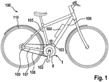
- FIG. 1 schematically shows an electric bicycle 100, in which a drive unit 1 is arranged centrally on the frame.
- a drive unit 1 is arranged centrally on the frame.
- the seat tube 105, the down tube 106 and the chain stay 107 converge on or near the drive unit 1.
- the bearing of the crankshaft for the pedal arms 102 and 103 is integrated in the drive unit 1.
- the drive unit has a chainring 8, which represents the output of the drive unit 1.
- the chainring 8 transmits a torque from the drive unit 1 via a chain 108 and a pinion 109 to a rear wheel 110.
- the drive unit 1 comprises an electric motor, not explicitly shown.
- the electric motor can be supplied with energy from a battery 104.
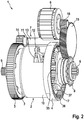
- FIG. 2 shows in a perspective view of an integrated drive unit 1, which has a friction ring gear 2, a pre-gear 3, a follower 4, a summation gear 5, an electric motor 6, an intermediate gear 7, an output 8 and a crankshaft 9.
- the crankshaft 9 is shown without its cranks, which can be attached to a tooth connection at the end of the crankshaft 9, wherein other types of connection are conceivable.
- the friction-ring transmission 2 has a housing 10 which at least radially surrounds the friction-ring transmission 2 except for an aperture 11. Through the opening 11 protrudes from the interior of the housing as part of the friction gear, an adjusting lever 12. This is displaceable in the longitudinal direction of the crankshaft 9, whereby the transmission ratio of the friction ring 2 is adjustable.
- the displacement of the adjustment lever 12 carried out with the adjusting thus extends with respect to the adjusting lever 12 in the interior of the aperture 11 and in the longitudinal direction of the crankshaft 9.
- the adjustment is at least approximately linear.
- the intermediate gear 7 comprises an intermediate shaft 13, at one end of a pinion 14 is arranged, which meshes with the summation gear 5.
- the storage of the intermediate shaft 13 is not shown.
- the pinion 14 has a considerably smaller diameter than the summation gear 5.
- an intermediate gear 15 is arranged with a considerably larger diameter than the pinion 14.
- the intermediate gear 15 meshes with a driven gear 16 of an electric motor 6, which is part of the drive unit 1. In this way, a significant reduction of the rotational speed of the electric motor 6 to the rotational speed of the Summier leopardrades 5 is effected via the intermediate gear 7.
- a mechanical connection between the electric motor 6 and the housing 10 of the friction ring 2 is not shown.
- the additional gear 4 is designed as a planetary gear, the output of the planet carrier 17 is.
- the planet carrier 17 is rotatably connected to the output gear 8 of the integrated transmission unit.
- the drive of the planetary gear is via the sun gear 35, while the ring gear 36 is rotatably connected to the housing 10.
- An outer cover of the secondary gear 4 is not shown, which can be made completely closed.
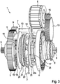
- FIG. 3 shows in a perspective view the same integrated drive unit 1 as FIG. 2 , but with the difference that the housing 10 of the friction ring transmission 2 is omitted, so that its details are visible. In addition, a part of the ring gear of the planetary gear as a feed gear 3 is omitted, so that its planet gears 18 and its planet carrier 19 are visible.
- FIG. 1 shows in a perspective view the same integrated drive unit 1 as FIG. 2 , but with the difference that the housing 10 of the friction ring transmission 2 is omitted, so that its details are visible.
- a part of the ring gear of the planetary gear as a feed gear 3 is omitted, so that its planet gears 18 and its planet carrier 19 are visible.
- FIG. 1 shows in a perspective view the same integrated drive unit 1 as FIG. 2 , but with the difference that the housing 10 of the friction ring transmission 2 is omitted, so that its details are visible.
- a part of the ring gear of the planetary gear as a feed gear 3 is
- the friction ring gear 2 comprises an outer friction ring 20 which is in frictional engagement with a plurality of double cones 23.
- the double cones 23 are arranged on a roller carrier 22 and run on axes 25 attached thereto.
- the roller carrier 22 has a non-visible part, which lies further inside the friction-ring transmission 2.
- the outer friction ring 20 is connected to a Sp Drettipplung 21, which in turn via a thrust bearing 24 at supported a housing part, not shown.
- the expansion clutch 21 spreads in the axial direction of the crankshaft 9 when a drive torque from the summation gear 5 acts on the friction-ring transmission 2. As a result, the contact pressure between the outer friction ring 20 and the double-cone rollers 23 is increased.
- the adjusting lever 12 is connected to the roller carrier 25, which is designed to be displaceable in the axial direction of the crankshaft 9.
- the expansion coupling 21 may comprise springs or be connected to springs, which cause a biasing force between the outer friction ring 20 and the double cone rollers 23.
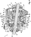
- FIG. 4 shows in perspective a cross section through the integrated drive unit 1, which in FIG. 3 is shown.
- the cross section extends through the central axis M of the crankshaft 9 and the adjusting lever 12.
- FIG. 4 the inner part of the roller carrier 22 is shown. This is connected via the roller axes 25 with the outer part of the roller carrier 22.
- the inner friction ring 26 is shown, which is in frictional engagement with the double cones 23.
- the inner friction ring 26 is associated with a Sp Drakupplung 27, which is supported against the housing 10 via a thrust bearing 28.
- the expansion clutch 28 is like the spreader 21 designed so that it is spread in a longitudinal direction of the crankshaft 9 at a force acting on the summation gear 5 drive torque, so that the contact pressure between the inner friction ring 26 and the double tapered rollers 23 is increased.
- the expansion coupling 27 may comprise springs or be connected to springs, which cause a biasing force between the inner friction ring 26 and the double cone rollers 23.
- the diameter of the Sp Dr Drkupplung 21 is smaller than that of the Sp Dr Drakupplung 27th
- a torque can be introduced via cranks not shown by pedal force in the crankshaft 9.
- the torque in the crankshaft 9 is via a freewheel 29 in the Summing gear 5 introduced.
- the freewheel 29 causes a reverse pedaling is possible, while the rest of the illustrated transmission rotates according to the revolutions of its output 8.
- the summation gear 5 is rotatably connected to the ring gear 30 of the feed gear 3, so that both rotate together.
- the planet gears 18 of the pilot gear 3 are mounted on planet shafts 31, which are fixed to the housing 10. The position of the planet gears 18 is thus fixed to its own rotation.
- the sun gear 32 of the pilot gear is rotatably connected to a sleeve 33 which conducts the torque from the sun gear 32 to the friction ring gear 2.
- the sleeve 33 is rotatably mounted on the crankshaft 9.
- a drive pulley 34 is pressed, which forwards the torque from the sleeve 33 via the Sp Schwarzringkupplung 21 to the outer friction ring 20. The torque is then transmitted to the double cone rollers 23.
- the roller carrier 22 Since the roller carrier 22 is not rotatable, but slidably disposed only in the longitudinal direction of the crankshaft 9, the torque is transmitted from the outer friction ring 20 completely in a rotation of the double-cone rollers 23. These transmit the torque further to the inner friction ring 26, with which they are also in frictional engagement. About the spreader 27, the torque is further transmitted to the sun gear 35 of the secondary gear 4.
- the ring gear 36 of the secondary gear 4 is rotatably connected to the housing 10. The torque is thus transmitted to the planet carrier 17 of the planetary gears 37 of the secondary transmission 4.
- the planetary carrier 17 of the secondary gear 4 is rotatably connected to the output preferably designed as a pinion 8, so that at this, for example via a chain, the torque from the integrated transmission unit 1 can be removed.
- the outer friction ring 20 and the inner friction ring 26 are, as already mentioned, supported by associated axial bearings 24 and 28 on the housing 10.
- the housing 10 forms in the embodiment of FIGS. 1 to 3 thus a force reflux device for the forces, which originate in particular from the Sp Schwarzkupplept 21 and 27. These forces correspond to the pressing forces on the double cone rollers 23.
- the thrust bearings 24 and 28 each run at the speed of the large friction ring 20 and the small Friction ring 26.
- the thrust bearing 24 of the large friction ring generates a relatively high frictional torque because it has a high speed and also a large frictional radius in many operating conditions.
- crankshaft 9 is concentrically arranged with the roller carrier 22, the thrust bearings 24 and 28, the Sp Drettipplept 21 and 27 and with the small friction ring 26 and the large friction ring 20.
- pre-gear 3 and the additional gear 4 which are both designed as a planetary gear, arranged concentrically to the crankshaft 9. The same applies to the summation gear 5 and the pinion of the output 8.
- FIG. 5 shows a section of the in FIG. 4 In a cross-section shown in perspective, which comprises the friction ring gear 2, in a view shown in half section.
- the drive pulley 34 comprises an axially bent edge 34 a, via which torque is conducted from the sleeve 33 to the spreader 21.
- FIG. 6 shows a slightly larger section of the FIG. 5 view, but with the difference that FIG. 6 a second embodiment of the drive unit 1 with a second embodiment of the friction ring 2 shows.
- the same features and elements are denoted by the same reference numerals as in the figures described above and will not be described separately again.
- the second embodiment FIG. 6 no thrust bearings 24 and 28, with which the friction ring gear is supported on the housing 10. Instead, serves as a force feedback device, the sleeve 33, which is equipped in the second embodiment with an axial force receiving portion 33 a.
- the force exerted by the inner friction ring 26 on the double cone rollers 23 force is transmitted via the spreader 27 on an angular contact ball bearings 38.
- This angular contact ball bearing 38 is attached with its inner ring on the sleeve 33 or pressed.
- An edge of an axial surface of the inner ring of the angular contact ball bearing 38 is axially supported on the Axialkraftabilityabexcellent 33 a of the sleeve 33 from.
- the axial forces corresponding to the pressure forces on the double cone rollers 23 are transmitted through the sleeve up to the pressure plate 34, which forwards them via their axial portion 34 a to the spreader coupling 21 and the outer friction ring 20. In this way, the power flow with which the double cone 23 is clamped closed.
- the angular contact ball bearing 38 runs at the differential speed of the outer friction ring 20 and the inner friction ring 26. This speed is lower than the speed of the inner and outer friction ring 26, 21 relative to the housing 10 in many operating conditions, which protects the bearing.
- FIG. 7 shows the same view of a cross section of the friction ring 2 in half-section as FIG. 6 but with the difference that in FIG. 7 a third embodiment of the friction ring 2 is shown.
- Like features and elements are designated by like reference numerals and will not be described again separately. It's on the FIG. 5 and the preceding figures described.
- the force feedback device in the embodiment of FIG. 7 realized with an integrally formed sleeve 33, which comprises a radially extending portion 33 b, which is part of the force feedback device.
- the drive pulley 34 is therefore not or hardly loaded by the back-pressing force of the friction rings and can transmit as its main load the torque from the sun gear 32 of the feed gear to the large friction ring 20. Due to the one-piece design of the sleeve 33 with its radially projecting portion 33b is given a higher reliability, because an alternative conceivable connection between the drive pulley 34 and the sleeve 33 can not fail due to the one-piece.
Landscapes
- Engineering & Computer Science (AREA)
- Mechanical Engineering (AREA)
- Chemical & Material Sciences (AREA)
- Combustion & Propulsion (AREA)
- Transportation (AREA)
- General Engineering & Computer Science (AREA)
- Friction Gearing (AREA)
- Mechanical Operated Clutches (AREA)
Description
- Die vorliegende Erfindung betrifft ein Reibringgetriebe für ein mit Motorkraft und/oder Pedalkraft betreibbares Fahrzeug mit einer Kurbelwelle für Tretkurbeln und mit einer Kurbelwellenmittelachse, die als theoretische und nicht als feststehende physische Achse zu verstehen ist, wobei das Reibringgetriebe insbesondere in einem Elektrofahrrad verwendet werden kann. Das Reibringgetriebe weist einen inneren Reibring und einen äußeren Reibring sowie wenigstens eine drehbare Doppelkegelrolle auf, die mit dem inneren und dem äußeren Reibring in Reibeingriff steht. Wenn ein Drehmoment übertragen wird, wirkt zum Zwecke der Reibungserzeugung zwischen der Doppelkegelrolle und den Reibringen jeweils eine Andruckkraft. Da diese Andruckkräfte zumindest zum Teil in entgegengesetzte Richtung auf die Doppelkegelrolle einwirken, existiert ein Kraftflusspfad zwischen dem inneren Reibring und dem äußeren Reibring, entlang dem Andruckkräfte von einem der Reibringe zu dem anderen geleitet werden. Innerhalb dieses Kraftflusspfades ist eine Kraftrückschlusseinrichtung zur Übertragung von Andruckkraft von einem Reibring zu dem anderen Reibring angeordnet. Dabei ist eines der Reibräder in Bezug auf die Kraftrückschlusseinrichtung drehfest angeordnet. Der andere Reibring ist in Bezug auf die Kraftrückschlusseinrichtung drehbar.
- Im Stand der Technik sind Fahrzeuge, insbesondere Elektrofahrräder bekannt, bei denen der Antrieb sowohl mit Muskelkraft als auch mit Motorkraft und insbesondere auch mit von Motorkraft unterstützter Muskelkraft möglich ist. Da es für die Trittfrequenz des Fahrers einen optimalen Bereich gibt und die mögliche Trittfrequenz nach oben begrenzt ist, sind Getriebe an solchen Fahrzeugen vorteilhaft, weil damit die Trittfrequenz in den optimalen bzw. möglichen Bereich gebracht werden kann. Reibringgetriebe haben die Vorteile, dass sie stufenlos und auch im Stand verstellbar sind. Nachteilig an einem Reibringgetriebe ist jedoch der vergleichsweise schlechte Wirkungsgrad, der sowohl durch die Reibvorgänge als auch durch Getriebekomponenten wie etwa Lager verursacht wird. Aus der
DE 10 2012 209 096 A1 ist ein Fahrradgetriebe nach dem Grundprinzip des Doppelkegel-Reibring-Getriebes bekannt, das in Tretlagernähe und in achsparalleler Anordnung zur Kurbelwelle in einen Pedelec-/eBike-Antrieb integriert ist. In derWO 2014/026 754 A1 ist ein Fahrradgetriebe, welches ein solches Doppelkegel-Reibring-Getriebe umfasst, in ebenfalls achsparalleler Anordnung zur Kurbelwelle und in Tretlagernähe beschrieben. - Nachteilig an der Konstruktion des Reibringgetriebes nach der
DE 10 2012 209 096 A1 ist, dass die Kraftrückschlusseinrichtung, welche das Anpressen der Reibringe an die Doppelkegel ermöglicht, außen um das Reibringgetriebe herum verläuft. Dadurch ist die Kraftrückschlusseinrichtung ein Teil mit einer großen Oberfläche und dementsprechend schwer, was dem für Fahrzeuge allgemein gültigen Leichtbaugedanken entgegen spricht. - Nachteilig an den bekannten Getrieben ist weiter, dass die Verstellung des Übersetzungsverhältnisses ausschließlich durch das Innere der Antriebs- oder Abtriebswelle des Reibringgetriebes und als Verstellung per Gewinde ausgeführt ist. Dies behindert erheblich die Konstruktionsfreiheit bei der Integration eines solchen Getriebes in ein Fahrzeug; insbesondere muss zur Verstellung eine Drehbewegung von einigen Umdrehungen erzeugt werden. Zudem ist diese Drehbewegung örtlich auf eine Mittenposition in Bezug auf das Getriebe festgelegt. Auch die Drehachse der Verstellrotation ist fest vorgegeben und verläuft koaxial zur Mittelachse des Getriebes.
- Das Dokument
US 2001/0024993 A1 offenbart ein CVT-Getriebe und in der SchriftDE 10 2012 023 150 A1 ist ein stufenloses Tretlagergetriebe beschrieben. In diesen Getrieben stehen jeweils verstellbare Doppelkegelrollen mit Reibringen in reibschlüssiger Verbindung DieUS 2001/0024993 A1 offenbart die Merkmale des Oberbegriffs des Anspruchs 1. - Das erfindungsgemäße Reibringgetriebe mit den Merkmalen des Anspruchs 1 weist eine Verstelleinrichtung für das Übersetzungsverhältnis des Reibringgetriebes auf, die entlang einer Verstellbahn beweglich ist. Die Verstellbahn hat eine Komponente ihres Verlaufs in Richtung einer Mittelachse des Rollenträgers, wobei sie zugleich höchstens weniger als eine ganze Umdrehung um das Reibringgetriebe herum verläuft, vorzugsweise weniger als 180 Grad, besonders bevorzugt weniger als 90 Grad. Ganz besonders bevorzugt verläuft die Verstellbahn gerade und folgt dabei der Richtung einer gedachten Mittelachse des Reibringgetriebes. Diese Mittelachse fällt üblicherweise mit der Mittelachse eines Rollenträgers der Doppelkegelrollen zusammen.
- Erfindungsgemäß
durchdringt die Verstelleinrichtung ein das Reibringgetriebe umgebendes Gehäuse. Die Verstellbahn verläuft erfindungsgemäß entlang einer Aussparung in dem Gehäuse. Erfindungsgemäß ist die Verstellbahn weniger als 360 Grad, bevorzugt weniger als 180 Grad, stärker bevorzugt weniger als 90 Grad, umläuft. Das Gehäuse kann dann insbesondere einstückig hergestellt werden, was im Allgemeinen weniger aufwendig ist als eine mehrstückige Verbundlösung. Besondere Festigkeit des Gehäuses wird erreicht, wenn wenigstens eine halbe Umdrehung des Gehäuses von der Verstellbahn nicht durchbrochen ist. Weniger als 90 Grad Umlauf der Verstellbahn um das Reibringgetriebe hat den Vorteil, dass durch den geringeren Umgriffswinkel die Verstellung vereinfacht ist. Eine besonders einfache Verstellung ergibt sich bei einer rein linearen Bewegung im Wesentlichen in Richtung der Mittelachse des Rollenträgers. Erfindungsgemäß ist die Verstelleinrichtung fest mit dem Rollenträger verbunden, d.h., sie ist zu diesem nicht beweglich, sodass eine Betätigung der Verstelleinrichtung den Rollenträger in axialer Richtung unmittelbar verschiebt, wodurch die Übersetzung des Reibringgetriebes geändert wird. Es ist denkbar, dass der Rollenträger beim Verstellen gedreht wird, vorzugsweise wird der Rollenträger jedoch nicht gedreht und ausschließlich linear verschoben. Erfindungsgemäß weist die Verstelleinrichtung kein Verstellgewinde auf. Die Verstelleinrichtung verläuft vorzugsweise nicht durch die zentrale Mitte des Reibringgetriebes. Die erfindungsgemäße Verstelleinrichtung schafft die Möglichkeit, die Übersetzung des Reibringgetriebes schnell und einfach einzustellen. - Vorzugsweise verlaufen der innere und der äußere Reibring um die Kurbelwelle. Dies ermöglicht, die Kurbelwelle im Zentrum des Reibringgetriebes anzuordnen. Bevorzugt ist das Reibringgetriebe mit einem Traktionsfluid gefüllt, welches gute Schmiereigenschaften besitzt und im intensiven Reibkontakt dennoch eine hohe Reibung zwischen den Reibpartnern bewirkt.
- Ein Reibringgetriebe mit der erfindungsgemäßen Verstellung wird besonders bevorzugt am Tretlager eingebaut. Ebenfalls bevorzugt ist eine integrierte Bauweise mit dem Tretlager und dem Motor. Dadurch ergeben sich die Vorteile einer optimalen Massenverteilung, welche durch einen tiefen, zentralen Schwerpunkt und ein leichtes Hinterrad erreicht wird. Es ergeben sich ein verbessertes Handling, geringere gefederte Massen und eine gute Fahrdynamik. Außerdem wird die Montage und Demontage des Hinterrades vereinfacht. Der Fahrradhersteller muss außerdem nur eine einzige integrierte Antriebseinheit statt mehrerer separater Komponenten in das Fahrrad einbauen. Dem Kunden kann ein einheitliches Modul aus Übersetzungs- und Antriebssteuerung präsentiert werden.
- Die Unteransprüche zeigen bevorzugte Weiterbildungen der Erfindung.
- In einer Ausführungsform verläuft die Kraftrückschlusseinrichtung innerhalb der Reibringe. Auf diese Weise wird im Vergleich zu der nach dem Stand der Technik außerhalb der Reibringe verlaufenden Kraftrückschlusseinrichtung Gewicht eingespart. Vorzugsweise erstreckt sich zumindest ein Abschnitt der Kraftrückschlusseinrichtung in Richtung der Mittelachse des Rollenträgers. Insbesondere weist dieser Abschnitt einen kleineren Durchmesser als der Reibdurchmesser des inneren Reibrings auf. Besonders vorteilhaft ist dabei, dass die gemäß dieser Ausführungsform innen umlaufenden Kraftrückschlusseinrichtung den Verlauf der Verstelleinrichtung von dem Reibringträger zu einem Durchbruch in dem Gehäuse erlaubt. Nach dem Stand der Technik ist dieser erforderliche Bauraum zwischen dem Rollenhalter und dem Gehäuse durch die umlaufende Kraftrückschlusseinrichtung bereits belegt.
- In einer weiteren Ausführungsform sind der Rollenträger und das Gehäuse des Reibringgetriebes drehfest miteinander verbunden. Jedoch lässt sich der Rollenträger gegenüber den Reibrädern verschieben. Die Reibräder sind dabei drehbar ausgestaltet, jedoch bevorzugt in ihrer Position gegenüber dem Gehäuse bis auf diese Drehung fixiert. Die Verstelleinrichtung kann mit dem Rollenträger fest verbunden sein. Sie kann als beweglicher Ausleger ausgestaltet sein, welcher insbesondere von dem Rollenträger bis außerhalb des Getriebes verläuft. Dabei verläuft der Ausleger bevorzugt durch das Gehäuse hindurch. Durch drehfeste Verbindung mit dem Gehäuse ist ein Verlauf der Verstellbahn entlang deiner Mittelachse des Getriebes bzw. des Rollenträgers möglich.
- In einer weiteren Ausführungsform ist das Fahrzeug mit einem Stellmotor ausgestattet, mit dem die Verstelleinrichtung verstellbar ist. Der Stellmotor kann an dem Reibringgetriebe angeordnet sein und/oder in einer integrierten Einheit von Motor, Getriebe und Kurbelwelle angeordnet sein.
- In einer weiteren Ausführungsform umfasst das Reibringgetriebe zwei Spreizkupplungen, welche sich unter Last aufspreizen und den Anpressdruck zwischen den Reibringen und den Doppelkegelrollen erhöhen. Je eine der Spreizkupplungen ist vorzugsweise je einem der Reibringe zugeordnet. Die Spreizkupplungen sind ringförmig ausgebildet, wobei sich der Kraftrückflusspfad zumindest durch eine der Spreizkupplungen hindurch erstreckt.
- In einer weiteren Ausführungsform ist die Kraftrückschlusseinrichtung um die Kurbelwelle für die Pedalkurbeln des Fahrzeuges herum angeordnet.
Insbesondere ist die Kraftrückschlusseinrichtung im Wesentlichen als eine Hülse ausgebildet, wobei diese einen sich axial entlang der Kurbelwelle erstreckenden Abschnitt sowie einen sich radial in Richtung zu wenigstens einem der Reibringe hin erstreckenden Abschnitt aufweist. Diese Ausgestaltung ist leichtgewichtig und außerdem einfach im Aufbau und daher leicht herzustellen. Der radial verlaufende Abschnitt kann von dem axial verlaufenden Abschnitt getrennt hergestellt und danach zusammengefügt sein, sodass sich danach eine einstückige oder eine zusammengesetzte Hülse ergibt. - In einer weiteren Ausführungsform ist die innenliegende Kraftrückschlusseinrichtung drehbar in Bezug auf die Kurbelwelle ausgeführt. Auf diese Weise kann die Drehzahl eines drehfest mit der Kraftrückschlusseinrichtung verbundenen Reibrings sich von der Drehzahl der Kurbelwelle unterscheiden. Auf diese Weise kann die Kurbelwelle ins Innere des Reibringgetriebes integriert werden.
- In einer weiteren Ausführungsform ist dem Reibringgetriebe ein Vorgetriebe vorgeschaltet, welches die Drehzahl des Reibringgetriebes erhöht. Insbesondere in einer integrierten Anordnung, in der die Kurbelwelle im Inneren des Reibringgetriebes verläuft, wird ein Planetengetriebe bevorzugt, welches ebenfalls konzentrisch zur Kurbelwelle angeordnet ist. Ein Vorteil der höheren Drehzahl des Reibringgetriebes ist, dass geringere Drehmomente auftreten. Auf diese Weise kann die zu übertragende Reibkraft gesenkt werden. Dadurch wiederum kann das Reibringgetriebe leichter ausgeführt werden.
- Vorzugsweise ist dem Reibringgetriebe ein Nachgetriebe nachgeschaltet, das vorzugsweise als Planetengetriebe ausgeführt ist und die Abtriebsdrehzahl des Reibradgetriebes an seinem eigenen Abtrieb verringert. Dadurch wird das Drehmoment am Abtrieb erhöht. Insbesondere kann das Nachgetriebe mit seiner Untersetzung die Übersetzung des Vorgetriebes wieder aufheben.
- Vorzugsweise wird das Vorgetriebe mit einem Drehmoment angetrieben, welches auf der Kurbelwelle anliegt. Dazu kann mit der Kurbelwelle ein Zahnrad verbunden sein, in welches deren Drehmoment übertragen werden kann. Im Falle eines Planetengetriebes als Vorgetriebe ist bevorzugt dessen Hohlrad auf der Kurbelwelle drehfest befestigt. Alternativ zu einer drehfesten Befestigung kann im Verlauf der Drehmomentübertragung zwischen der Kurbelwelle und dem Hohlrad auch ein Freilauf angeordnet sein, der ein Rückwärtspedalieren unabhängig von der Drehung des Motors ermöglicht. Vorzugsweise wird mit dem Abtrieb des Vorgetriebes ein Reibring des Reibringgetriebes angetrieben. Der Reibring kann angetrieben sein, indem die Kraftrückschlusseinrichtung von dem Vorgetriebe angetrieben wird. Vorzugsweise wird der größere bzw. der äußere der Reibringe angetrieben. Besonders bevorzugt ist die Kraftrückschlusseinrichtung drehfest mit dem größeren der beiden Reibräder verbunden.
- In einer weiteren Ausführungsform ist der kleinere bzw. der innere der beiden Reibringe in Bezug auf die Kraftrückschlusseinrichtung drehbar angeordnet, insbesondere über ein Wälzlager. Dies ermöglicht in vielen Fällen, dass für diese Funktion ein kleines Kugellager mit geringem Durchmesser verwendet wird, welches ein geringes Verlustdrehmoment erzeugt und leicht ist.
- In einer weiteren Ausführungsform umfasst das Reibringgetriebe ein Summierzahnrad, welches dazu dient, die Drehmomente zu addieren, die aus Muskelkraft und motorisch erzeugt werden. Das Summierzahnrad kann mit einem der beiden Reibringe drehfest verbunden sein. Besonders bevorzugt ist es jedoch mit dem größeren Reibring drehfest verbunden, was in einer Ausführungsform mit Vorgetriebe bedeuten kann, dass es mit dem Abtrieb des Vorgetriebes verbunden ist. Die Summierung geschieht durch Einleiten von Drehmoment in das Summierzahnrad auf verschiedenen Wegen, nämlich zentral durch eine Welle, auf die das Summierzahnrad aufgesetzt wird und durch ein weiteres Zahnrad, welches in den Außenumfang des Summierzahnrads eingreift. Bevorzugt ist dieses weitere Zahnrad ein Zahnrad, welches von dem Motor antreibbar ist.
- In einer weiteren Ausführungsform ist zwischen der Kraftrückschlusseinrichtung und einem der Reibräder ein Wälzlager angeordnet, in welchem die Kraftübertragungslinie in einem spitzen Winkel zu der Mittelachse des Rollenträgers steht. Über das Lager verlaufen Andruckkräfte zwischen den Reibringen und den Rollen, die Axialkräfte darstellen. Außerdem erfüllt es die Funktion einer radialen Führung der zueinander drehbar gelagerten Teile. Vorzugsweise werden deshalb Schrägkugellager oder Kegelrollenlager eingesetzt. Vorzugsweise verläuft die Kraftrückschlusseinrichtung im Inneren des Wälzlagers. Vorzugsweise ist der Innenring auf die Kraftrückschlusseinrichtung aufgesteckt oder aufgepresst. Dies ermöglicht einen einfachen Aufbau des Reibringgetriebes. Das Wälzlager läuft vorteilhaft mit der Differenzdrehzahl zwischen der Drehzahl des inneren und des äußeren Reibringes, die in vielen Betriebszuständen geringer als die Drehzahlen der Reibringe selbst ist. Dadurch werden die Lagerverluste und der Lagerverschleiß im Vergleich zu einer Lösung nach dem Stand der Technik, in der die Reibringe einzeln mit Axiallagern an dem Gehäuse abgestützt sind, verringert.
- In einem weiteren Aspekt der Erfindung wird ein mit Motorkraft und/oder Pedalkraft betreibbares Fahrzeug vorgeschlagen, welches ein Reibringgetriebe gemäß einer der vorstehend beschriebenen Ausführungsformen aufweist.
- In noch einem weiteren Aspekt wird eine Antriebseinrichtung für ein mit Motorkraft und/oder Pedalkraft betreibbares Fahrzeug vorgeschlagen, welche ein Reibringgetriebe gemäß einer der vorstehend beschriebenen Ausführungsformen aufweist.
- Nachfolgend werden Ausführungsbeispiele der Erfindung unter Bezugnahme auf die begleitenden Zeichnungen im Detail beschrieben. In den Zeichnungen ist:
- Figur 1
- eine schematische Darstellung eines Elektrofahrrades, welches eine Ausführungsform des erfindungsgemäßen Reibringgetriebes aufweist.
- Figur 2
- eine perspektivische Ansicht einer integrierten Antriebseinheit mit einem erfindungsgemäßen Reibringgetriebe,
- Figur 3
- eine perspektivische Ansicht der integrierten Antriebseinheit in der in
Figur 2 gezeigten Ausführungsform ohne ein das Reibringgetriebe umgebendes Gehäuse, - Figur 4
- ein Querschnitt durch eine Mittelachse des Rollenträgers verlaufender Querschnitt durch die in
Figur 3 gezeigte Antriebseinheit mit Summierzahnrad, Vorgetriebe, Reibringgetriebe und Nachgetriebe, - Figur 5
- vergrößert ein Detail mit einer Doppelkegelrolle aus dem in
Figur 4 gezeigten Querschnitt, - Figur 6
- eine zweite Ausführungsform der Antriebseinheit mit einer zweiten Ausführungsform des Reibringgetriebes mit einer als Hülse ausgebildeten Kraftrückschlusseinrichtung und einem Schrägkugellager, und
- Figur 7
- eine dritte Ausführungsform der Antriebseinheit mit einer dritten Ausführungsform des Reibringgetriebes mit einer anderen als Hülse ausgebildeten Kraftrückschlusseinrichtung.
-
Figur 1 zeigt schematisch ein Elektrofahrrad 100, in welchem eine Antriebseinheit 1 zentral an dem Rahmen angeordnet ist. Insbesondere laufen an oder nahe der Antriebseinheit 1 das Sitzrohr 105, das Unterrohr 106 und die Kettenstrebe 107 zusammen. Die Lagerung der Kurbelwelle für die Pedalarme 102 und 103 ist in die Antriebseinheit 1 integriert. Die Antriebseinheit weist ein Kettenblatt 8 auf, welches den Abtrieb der Antriebseinheit 1 darstellt. Das Kettenblatt 8 überträgt ein Drehmoment von der Antriebseinheit 1 über eine Kette 108 und ein Ritzel 109 zu einem Hinterrad 110. Die Antriebseinheit 1 umfasst einen nicht explizit dargestellten Elektromotor. Der Elektromotor kann mit Energie aus einer Batterie 104 versorgt werden. -
Figur 2 zeigt in einer perspektivischen Ansicht eine integrierte Antriebseinheit 1, welche ein Reibringgetriebe 2, ein Vorgetriebe 3, ein Nachgetriebe 4, ein Summierzahnrad 5, einen Elektromotor 6, ein Zwischengetriebe 7, einen Abtrieb 8 und eine Kurbelwelle 9 aufweist. Die Kurbelwelle 9 ist ohne ihre Kurbeln dargestellt, welche jeweils auf eine Zahnverbindung am Ende der Kurbelwelle 9 aufgesteckt werden können, wobei auch andere Verbindungsarten denkbar sind. Das Reibringgetriebe 2 weist ein Gehäuse 10 auf, welches das Reibringgetriebe 2 bis auf einen Durchbruch 11 zumindest radial umgibt. Durch den Durchbruch 11 ragt aus dem Inneren des Gehäuses als Teil des Reibringgetriebes ein Verstellhebel 12 hervor. Dieser ist in Längsrichtung der Kurbelwelle 9 verschieblich, wodurch das Übersetzungsverhältnis des Reibringgetriebes 2 einstellbar ist. Der Verstellweg der mit dem Verstellhebel 12 ausgeführten Verstelleinrichtung verläuft somit in Bezug auf den Verstellhebel 12 im Inneren des Durchbruchs 11 und in Längsrichtung der Kurbelwelle 9. Der Verstellweg ist wenigstens näherungsweise linear. - Das Zwischengetriebe 7 umfasst eine Zwischenwelle 13, an deren einem Ende ein Ritzel 14 angeordnet ist, welches mit dem Summierzahnrad 5 kämmt. Die Lagerung der Zwischenwelle 13 ist nicht dargestellt. Das Ritzel 14 hat einen erheblich kleineren Durchmesser als das Summierzahnrad 5. Am anderen Ende der Zwischenwelle 13 ist ein Zwischenzahnrad 15 mit erheblich größerem Durchmesser als das Ritzel 14 angeordnet. Das Zwischenzahnrad 15 kämmt mit einem Abtriebszahnrad 16 eines Elektromotors 6, der Teil der Antriebseinheit 1 ist. Auf diese Weise wird über das Zwischengetriebe 7 eine erhebliche Untersetzung der Drehzahl des Elektromotors 6 zu der Drehzahl des Summierzahnrades 5 bewirkt. Eine mechanische Verbindung zwischen dem Elektromotor 6 und dem Gehäuse 10 des Reibringgetriebes 2 ist nicht dargestellt.
- Das Nachgetriebe 4 ist als Planetengetriebe ausgeführt, dessen Abtrieb der Planetenträger 17 ist. Der Planetenträger 17 ist drehfest mit dem Abtriebsritzel 8 der integrierten Getriebeeinheit verbunden. Der Antrieb des Planetengetriebes erfolgt über das Sonnenrad 35, während das Hohlrad 36 mit dem Gehäuse 10 drehfest verbunden ist. Eine äußere Abdeckung des Nachgetriebes 4 ist nicht dargestellt, welches vollständig geschlossen ausgeführt sein kann.
-
Figur 3 zeigt in einer perspektivischen Ansicht dieselbe integrierte Antriebseinheit 1 wieFigur 2 , jedoch mit dem Unterschied, dass das Gehäuse 10 des Reibringgetriebes 2 weggelassen ist, sodass dessen Details sichtbar sind. Außerdem ist ein Teil des Hohlrades des als Planetengetriebe ausgeführten Vorgetriebes 3 weggelassen, sodass seine Planetenräder 18 und sein Planetenträger 19 sichtbar sind. Merkmale und Elemente, die inFigur 1 beschrieben wurden, sind mit gleichen Bezugszeichen versehen und werden nicht noch einmal gesondert beschrieben. Es sei aufFigur 1 verwiesen. - Das Reibringgetriebe 2 umfasst einen äußeren Reibring 20, welcher mit mehreren Doppelkegeln 23 in Reibeingriff steht. Die Doppelkegel 23 sind auf einem Rollenträger 22 angeordnet und laufen auf daran befestigten Achsen 25 um. Der Rollenträger 22 hat einen nicht sichtbaren Teil, der weiter im Inneren des Reibringgetriebes 2 liegt. Der äußere Reibring 20 ist mit einer Spreizkupplung 21 verbunden, welche sich wiederum über ein Axiallager 24 an einem nicht dargestellten Gehäuseteil abstützt. Die Spreizkupplung 21 spreizt sich in axialer Richtung der Kurbelwelle 9 auf, wenn ein Antriebsmoment von dem Summierzahnrad 5 auf das Reibringgetriebe 2 einwirkt. Dadurch wird der Anpressdruck zwischen dem äußeren Reibring 20 und den Doppelkegelrollen 23 erhöht. Der Verstellhebel 12 ist mit dem Rollenträger 25 verbunden, welcher in Axialrichtung der Kurbelwelle 9 verschieblich ausgeführt ist. Die Spreizkupplung 21 kann Federn umfassen oder mit Federn verbunden sein, die eine Vorspannkraft zwischen dem äußeren Reibring 20 und den Doppelkegelrollen 23 bewirken.
-
Figur 4 zeigt perspektivisch einen Querschnitt durch die integrierte Antriebseinheit 1, die inFigur 3 dargestellt ist. Der Querschnitt verläuft durch die Mittelachse M der Kurbelwelle 9 und den Verstellhebel 12. Bereits in denFiguren 2 und3 beschriebene Merkmale und Elemente sind mit denselben Bezugsziffern bezeichnet und werden nicht noch einmal gesondert beschrieben. Es sei auf dieFiguren 2 und3 verwiesen. - In
Figur 4 ist der innere Teil des Rollenträgers 22 dargestellt. Dieser ist über die Rollenachsen 25 mit dem äußeren Teil des Rollenträgers 22 verbunden. Weiter ist der innere Reibring 26 dargestellt, welcher mit den Doppelkegeln 23 in Reibeingriff steht. Dem inneren Reibring 26 ist eine Spreizkupplung 27 zugeordnet, welche sich gegen das Gehäuse 10 über ein Axiallager 28 abstützt. Die Spreizkupplung 28 ist wie die Spreizkupplung 21 so ausgelegt, dass sie bei einem auf das Summierzahnrad 5 einwirkenden Antriebsdrehmoment in Längsrichtung der Kurbelwelle 9 gespreizt wird, sodass der Anpressdruck zwischen dem inneren Reibring 26 und den Doppelkegelrollen 23 erhöht wird. Die Spreizkupplung 27 kann Federn umfassen oder mit Federn verbunden sein, die eine Vorspannkraft zwischen dem inneren Reibring 26 und den Doppelkegelrollen 23 bewirken. Der Durchmesser der Spreizkupplung 21 ist kleiner als der der Spreizkupplung 27. - Im Folgenden wird der Kraftfluss durch den in
Figur 4 dargestellten Teil der Antriebseinheit 1 beschrieben. Ein Drehmoment kann über nicht dargestellte Kurbeln per Pedalkraft in die Kurbelwelle 9 eingebracht werden. Das Drehmoment in der Kurbelwelle 9 wird über einen Freilauf 29 in das Summierzahnrad 5 eingebracht. Der Freilauf 29 bewirkt, dass ein Rückwärtspedalieren möglich ist, während der Rest der dargestellten Getriebe den Umdrehungen seines Abtriebs 8 entsprechend umläuft. Das Summierzahnrad 5 ist mit dem Hohlrad 30 des Vorgetriebes 3 drehfest verbunden, sodass beide gemeinsam umlaufen. Die Planetenräder 18 des Vorgetriebes 3 sind auf Planetenwellen 31 gelagert, welche an dem Gehäuse 10 befestigt sind. Die Position der Planetenräder 18 ist somit bis auf ihre Eigendrehung fixiert. Das Sonnenrad 32 des Vorgetriebes ist mit einer Hülse 33 drehfest verbunden, die das Drehmoment von dem Sonnenrad 32 zu dem Reibringgetriebe 2 leitet. Durch die Übersetzung des Vorgetriebes 3 ist die Drehzahl der Hülse 33 höher als die Drehzahl des Summierzahnrades 5. Die Hülse 33 ist drehbar auf die Kurbelwelle 9 aufgesteckt. Auf die Hülse 33 ist eine Antriebsscheibe 34 aufgepresst, welche das Drehmoment von der Hülse 33 über die Spreizringkupplung 21 zu dem äußeren Reibring 20 weiterleitet. Das Drehmoment wird sodann auf die Doppelkegelrollen 23 übertragen. Da der Rollenträger 22 nicht drehbar, sondern nur in Längsrichtung der Kurbelwelle 9 verschieblich angeordnet ist, wird das Drehmoment von dem äußeren Reibring 20 vollständig in eine Drehung der Doppelkegelrollen 23 übertragen. Diese übertragen das Drehmoment weiter zu dem inneren Reibring 26, mit dem sie ebenfalls in Reibeingriff stehen. Über die Spreizkupplung 27 wird das Drehmoment weiter zu dem Sonnenrad 35 des Nachgetriebes 4 übertragen. Das Hohlrad 36 des Nachgetriebes 4 ist mit dem Gehäuse 10 drehfest verbunden. Das Drehmoment wird somit auf den Planetenträger 17 der Planetenräder 37 des Nachgetriebes 4 übertragen. Wie schon zuvor erwähnt, ist der Planetenträger 17 des Nachgetriebes 4 mit dem bevorzugt als Ritzel ausgeführten Abtrieb 8 drehfest verbunden, sodass an diesem, beispielsweise über eine Kette, das Drehmoment aus der integrierten Getriebeeinheit 1 abgenommen werden kann. - Der äußere Reibring 20 und der innere Reibring 26 sind wie schon erwähnt durch jeweils zugeordnete Axiallager 24 und 28 am Gehäuse 10 abgestützt. Das Gehäuse 10 bildet in der Ausführungsform der
Figuren 1 bis 3 somit eine Kraftrückflusseinrichtung für die Kräfte, die insbesondere aus den Spreizkupplungen 21 und 27 stammen. Diese Kräfte entsprechen den Presskräften auf die Doppelkegelrollen 23. Die Axiallager 24 und 28 laufen jeweils mit der Drehzahl des großen Reibringes 20 beziehungsweise des kleinen Reibringes 26. Insbesondere das Axiallager 24 des großen Reibringes erzeugt ein relativ hohes Reibmoment, weil es in vielen Betriebszuständen eine hohe Drehzahl und außerdem einen großen Reibradius aufweist. - Die Kurbelwelle 9 ist mit dem Rollenträger 22, den Axiallagern 24 und 28, den Spreizkupplungen 21 und 27 sowie mit dem kleinen Reibring 26 und dem großen Reibring 20 konzentrisch angeordnet. Außerdem sind das Vorgetriebe 3 und das Nachgetriebe 4, die beide als Planetengetriebe ausgeführt sind, konzentrisch zu der Kurbelwelle 9 angeordnet. Gleiches gilt auch für das Summierzahnrad 5 und das Ritzel des Abtriebs 8.
-
Figur 5 zeigt einen Ausschnitt aus dem inFigur 4 perspektivisch dargestellten Querschnitt, welcher das Reibringgetriebe 2 umfasst, in einer als Halbschnitt gezeigten Ansicht. Gleiche Merkmale und Elemente sind mit gleichen Bezugsziffern bezeichnet und werden nicht noch einmal gesondert beschrieben. Es sei diesbezüglich aufFigur 4 verwiesen. InFigur 5 ist gut zu erkennen, dass die Antriebsscheibe 34 einen in axiale Richtung umgebogenen Rand 34a umfasst, über welchen Drehmoment von der Hülse 33 zu der Spreizkupplung 21 geleitet wird. -
Figur 6 zeigt einen etwas größeren Ausschnitt der inFigur 5 gezeigten Ansicht, jedoch mit dem Unterschied, dassFigur 6 eine zweite Ausführungsform der Antriebseinheit 1 mit einer zweiten Ausführungsform des Reibringgetriebes 2 zeigt. Gleiche Merkmale und Elemente sind mit denselben Bezugsziffern wie in den vorstehend beschriebenen Figuren bezeichnet und werden nicht noch einmal gesondert beschrieben. - Im Unterschied zu der in
Figur 5 gezeigten ersten Ausführungsform weist die zweite Ausführungsform inFigur 6 keine Axiallager 24 und 28 auf, mit denen sich das Reibringgetriebe an dem Gehäuse 10 abstützt. Stattdessen dient als Kraftrückschlusseinrichtung die Hülse 33, die in der zweiten Ausführungsform mit einem Axialkraftaufnahmeabschnitt 33a ausgestattet ist. Die von dem inneren Reibring 26 auf die Doppelkegelrollen 23 ausgeübte Kraft wird über die Spreizkupplung 27 auf ein Schrägkugellager 38 übertragen. Dieses Schrägkugellager 38 ist mit seinem Innenring auf die Hülse 33 aufgesteckt oder aufgepresst. Eine Kante einer Axialfläche des Innenrings des Schrägkugellagers 38 stützt sich axial an dem Axialkraftaufnahmeabschnitt 33a der Hülse 33 ab. Die Axialkräfte, die den Andruckkräften an die Doppelkegelrollen 23 entsprechen, werden durch die Hülse bis zu der Andruckscheibe 34 weitergeleitet, welche sie über ihren Axialabschnitt 34a zu der Spreizkupplung 21 und dem äußeren Reibring 20 weiterleitet. Auf diese Weise ist der Kraftfluss, mit welchem der Doppelkegel 23 eingeklemmt ist, geschlossen. Das Schrägkugellager 38 läuft mit der Differenzgeschwindigkeit des äußeren Reibrings 20 und des inneren Reibringes 26 um. Diese Drehzahl ist in vielen Betriebszuständen geringer als die Drehzahl des inneren beziehungsweise äußeren Reibringes 26, 21 gegenüber dem Gehäuse 10, was das Lager schont. -
Figur 7 zeigt dieselbe Ansicht eines Querschnitts des Reibringgetriebes 2 im Halbschnitt wieFigur 6 , jedoch mit dem Unterschied, dass inFigur 7 eine dritte Ausführungsform des Reibringgetriebes 2 dargestellt ist. Gleiche Merkmale und Elemente sind mit gleichen Bezugsziffern bezeichnet und werden nicht noch einmal gesondert beschrieben. Es sei auf dieFigur 5 und die vorangehende beschriebenen Figuren verwiesen. - Im Unterschied zu der Ausführungsform der
Figur 6 ist die Kraftrückschlusseinrichtung in der Ausführungsform derFigur 7 mit einer einstückig ausgeführten Hülse 33 realisiert, welche einen sich radial erstreckenden Abschnitt 33b umfasst, welcher Teil der Kraftrückschlusseinrichtung ist. Die Antriebsscheibe 34 ist daher von der zurückfließenden Presskraft der Reibringe nicht oder kaum belastet und kann als seine Hauptlast das Drehmoment von dem Sonnenrad 32 des Vorgetriebes zu dem großen Reibring 20 übertragen. Durch die einstückige Ausführung der Hülse 33 mit ihrem radial auskragenden Abschnitt 33b ist eine höhere Ausfallsicherheit gegeben, weil eine alternativ denkbare Verbindung zwischen der Antriebsscheibe 34 und der Hülse 33 aufgrund der Einstückigkeit nicht versagen kann.
Claims (14)
- Reibringgetriebe (2) für ein mit Motorkraft und/oder Pedalkraft betreibbares Fahrzeug (100) mit einer Kurbelwelle (9) für Tretkurbeln (102, 103), insbesondere für ein Elektrofahrrad, wobei- das Reibringgetriebe (2) einen inneren Reibring (26) und einen äußeren Reibring (20) sowie wenigstens eine auf einem Rollenträger (22) angeordnete, drehbare Doppelkegelrolle (23) aufweist, die bei einer Drehmomentübertragung über das Reibringgetriebe (2) mit dem inneren Reibrad (26) und dem äußeren Reibring (20) jeweils unter einer Andruckkraft in Reibeingriff steht,- wobei in einem Kraftflusspfad von dem inneren Reibring (26) zu dem äußeren Reibring (20) eine Kraftrückschlusseinrichtung zur Übertragung von Andruckkraft von einem Reibring (20, 26) zu dem anderen Reibring (20, 26) angeordnet ist, wobei einer der Reibringe (20, 26) in Bezug auf die Kraftrückschlusseinrichtung drehfest angeordnet ist und der andere Reibring (26, 20) in Bezug auf die Kraftrückschlusseinrichtung drehbar angeordnet ist, und- das Reibringgetriebe (2) eine Verstelleinrichtung (12) für das Übersetzungsverhältnis aufweist und diese Verstelleinrichtung (12) entlang eines Verstellweges beweglich ist, der in Richtung einer Mittelachse (M) der Reibringe (20, 26) verläuft, und- der Rollenträger (22) und die Verstelleinrichtung (12) sowie zumindest ein Abschnitt eines Gehäuses (10) des Reibringgetriebes (2) nicht rotierend angeordnet sind
dadurch gekennzeichnet, dass- die Verstelleinrichtung (12) zugleich weniger als 360 Grad um eine Mittelachse (M) des Rollenträgers (22) herum verläuft,- die Verstelleinrichtung (12) durch den Abschnitt des Gehäuses (10) hindurch verläuft, und- die Verstelleinrichtung (12) fest mit dem Rollenträger (22) verbunden ist, sodass eine Betätigung der Verstelleinrichtung den Rollenträger in axialer Richtung unmittelbar verschiebt, wobei die Verstelleinrichtung kein Verstellgewinde aufweist. - Reibringgetriebe (2) nach Anspruch 1, dadurch gekennzeichnet, dass die Kraftrückschlusseinrichtung innerhalb der Reibringe (20, 26) verläuft.
- Reibringgetriebe (2) nach dem Anspruch 2 dadurch gekennzeichnet, dass das Reibringgetriebe (2) einen Stellmotor zur Verstellung der Verstelleinrichtung (12) aufweist.
- Reibringgetriebe (2) nach einem der vorangehenden Ansprüche, dadurch gekennzeichnet, dass das Reibringgetriebe (2) zwei ringförmige Spreizkupplungen (21, 27) aufweist, durch welche sich die Kraftrückschlusseinrichtung erstreckt, wobei insbesondere wenigstens eine Spreizkupplung (21, 27) zwischen der Kraftrückschlusseinrichtung und einem Reibring (20, 26) angeordnet ist.
- Reibringgetriebe (2) nach einem der vorangehenden Ansprüche, dadurch gekennzeichnet, dass die Kraftrückschlusseinrichtung um eine Kurbelwelle (9) herum angeordnet ist und insbesondere als Hülse (33) ausgebildet ist, insbesondere als einstückige Hülse (33).
- Reibringgetriebe (2) nach Anspruch 5, dadurch gekennzeichnet, dass die Kraftrückschlusseinrichtung einen sich radial von der Kurbelwelle (9) weg erstreckenden Abschnitt (33a, 34, 34a) zur Verbindung mit einem der Reibringe (20, 26) aufweist oder dieser Abschnitt (33a, 34, 34a) einstückig mit einem Reibring (20, 26) ausgeführt ist.
- Reibringgetriebe (2) nach einem der vorangehenden Ansprüche, dadurch gekennzeichnet, dass dem Reibringgetriebe (2) ein Vorgetriebe (3) vorgeschaltet ist, das die Drehzahl des Reibradgetriebes (2) gegenüber der Antriebsdrehzahl des Vorgetriebes (3) erhöht, wobei das Vorgetriebe (3) insbesondere ein Planetengetriebe (18, 30, 31, 32) ist.
- Reibringgetriebe (2) nach einem der vorangehenden Ansprüche, dadurch gekennzeichnet, dass die Kraftrückschlusseinrichtung mit einem Antriebselement des Reibringgetriebes (2), insbesondere einer Welle oder einem Zahnrad, insbesondere einem Abtriebssonnenrad (32) eines Planetengetriebes (18, 30, 31, 32), drehfest verbunden ist.
- Reibringgetriebe (2) nach einem der vorangehenden Ansprüche, dadurch gekennzeichnet, dass der kleinere Reibring (26) gegenüber der Kraftrückschlusseinrichtung drehbar angeordnet ist.
- Reibringgetriebe (2) nach einem der vorangehenden Ansprüche, dadurch gekennzeichnet, dass das Reibringgetriebe (2) ein Summierzahnrad (5) zum Summieren der Drehmomente von der Kurbelwelle (9) und einem Elektromotor (6) aufweist.
- Reibringgetriebe (2) nach einem der vorangehenden Ansprüche, dadurch gekennzeichnet, dass zwischen der Kraftrückschlusseinrichtung und einem der Reibringe (20, 26) ein Wälzlager (38) angeordnet ist, in welchem eine Drucklinie zwischen Berührungsstellen eines Wälzkörpers an die Laufringe in einem spitzen Winkel zu der Mittelachse (M) des Rollenträgers (22) steht, wobei das Wälzlager (38) insbesondere als Schrägkugellager oder als Kegelrollenlager ausgebildet ist.
- Reibringgetriebe (2) nach Anspruch 11, dadurch gekennzeichnet, dass die Kraftrückschlusseinrichtung von dem Wälzlager (38) radial umgeben ist, wobei insbesondere ein innerer Laufring des Wälzlagers (38) auf einer Außenoberfläche der Kraftrückschlusseinrichtung angeordnet ist und sich bevorzugt axial an dieser abstützt.
- Mit Motorkraft und/oder Pedalkraft betreibbares Fahrzeug (100), dadurch gekennzeichnet, dass das Fahrzeug (100) ein Reibringgetriebe (2) nach einem der vorangehenden Ansprüche aufweist.
- Fahrzeug (100) nach Anspruch 13, dadurch gekennzeichnet, dass das Fahrzeug (100) einen Stellmotor zur Verstellung der Verstelleinrichtung (12) aufweist.
Applications Claiming Priority (2)
| Application Number | Priority Date | Filing Date | Title |
|---|---|---|---|
| DE102014221514.5A DE102014221514A1 (de) | 2014-10-23 | 2014-10-23 | Verstellbares Reibringgetriebe für ein mit Motorkraft und/oder Pedalkraft betreibbares Fahrzeug |
| PCT/EP2015/071065 WO2016062461A1 (de) | 2014-10-23 | 2015-09-15 | Verstellbares reibringgetriebe für ein mit motorkraft und/oder pedalkraft betreibbares fahrzeug |
Publications (2)
| Publication Number | Publication Date |
|---|---|
| EP3209543A1 EP3209543A1 (de) | 2017-08-30 |
| EP3209543B1 true EP3209543B1 (de) | 2019-07-24 |
Family
ID=54106370
Family Applications (1)
| Application Number | Title | Priority Date | Filing Date |
|---|---|---|---|
| EP15763335.5A Active EP3209543B1 (de) | 2014-10-23 | 2015-09-15 | Verstellbares reibringgetriebe für ein mit motorkraft und/oder pedalkraft betreibbares fahrzeug |
Country Status (5)
| Country | Link |
|---|---|
| US (1) | US20170305499A1 (de) |
| EP (1) | EP3209543B1 (de) |
| JP (1) | JP6415711B2 (de) |
| DE (1) | DE102014221514A1 (de) |
| WO (1) | WO2016062461A1 (de) |
Families Citing this family (31)
| Publication number | Priority date | Publication date | Assignee | Title |
|---|---|---|---|---|
| US7011600B2 (en) | 2003-02-28 | 2006-03-14 | Fallbrook Technologies Inc. | Continuously variable transmission |
| KR101276082B1 (ko) | 2004-10-05 | 2013-06-18 | 폴브룩 테크놀로지즈 인크 | 연속 가변 변속기 |
| KR101831828B1 (ko) | 2005-10-28 | 2018-02-23 | 폴브룩 인텔렉츄얼 프로퍼티 컴퍼니 엘엘씨 | 전동 드라이브 |
| EP1954959B1 (de) | 2005-11-22 | 2013-05-15 | Fallbrook Intellectual Property Company LLC | Stufenlos verstellbares getriebe |
| CA2976893C (en) | 2005-12-09 | 2019-03-12 | Fallbrook Intellectual Property Company Llc | Continuously variable transmission |
| EP1811202A1 (de) | 2005-12-30 | 2007-07-25 | Fallbrook Technologies, Inc. | Stufenloses Getriebe |
| EP2125469A2 (de) | 2007-02-01 | 2009-12-02 | Fallbrook Technologies Inc. | System und verfahren zur getriebe- und/oder antriebsmotorsteuerung |
| CN104121345B (zh) | 2007-02-12 | 2017-01-11 | 福博科知识产权有限责任公司 | 无级变速器及其方法 |
| EP2700843A3 (de) | 2007-02-16 | 2017-11-08 | Fallbrook Intellectual Property Company LLC | Stufenlose Getriebe, Verfahren, Anordnungen, Baugruppen und Komponenten dafür |
| CN102943855B (zh) | 2007-04-24 | 2016-01-27 | 福博科技术公司 | 电力牵引传动装置 |
| WO2008154437A1 (en) | 2007-06-11 | 2008-12-18 | Fallbrook Technologies Inc. | Continuously variable transmission |
| CN103697120B (zh) | 2007-07-05 | 2017-04-12 | 福博科技术公司 | 无级变速器 |
| US8996263B2 (en) | 2007-11-16 | 2015-03-31 | Fallbrook Intellectual Property Company Llc | Controller for variable transmission |
| JP5783723B2 (ja) | 2007-12-21 | 2015-09-24 | フォールブルック インテレクチュアル プロパティー カンパニー エルエルシー | 自動変速機及びその方法 |
| US8535199B2 (en) | 2008-06-06 | 2013-09-17 | Fallbrook Intellectual Property Company Llc | Infinitely variable transmissions, continuously variable transmissions, methods, assemblies, subassemblies, and components therefor |
| WO2009157920A1 (en) | 2008-06-23 | 2009-12-30 | Fallbrook Technologies Inc. | Continuously variable transmission |
| WO2010017242A1 (en) | 2008-08-05 | 2010-02-11 | Fallbrook Technologies Inc. | Methods for control of transmission and prime mover |
| US8469856B2 (en) | 2008-08-26 | 2013-06-25 | Fallbrook Intellectual Property Company Llc | Continuously variable transmission |
| US8167759B2 (en) | 2008-10-14 | 2012-05-01 | Fallbrook Technologies Inc. | Continuously variable transmission |
| WO2010120933A1 (en) | 2009-04-16 | 2010-10-21 | Fallbrook Technologies Inc. | Stator assembly and shifting mechanism for a continuously variable transmission |
| US8512195B2 (en) | 2010-03-03 | 2013-08-20 | Fallbrook Intellectual Property Company Llc | Infinitely variable transmissions, continuously variable transmissions, methods, assemblies, subassemblies, and components therefor |
| US8888643B2 (en) | 2010-11-10 | 2014-11-18 | Fallbrook Intellectual Property Company Llc | Continuously variable transmission |
| CN107061653B (zh) | 2012-01-23 | 2020-05-26 | 福博科知识产权有限责任公司 | 无限变速式无级变速器、连续变速式无级变速器、方法、组件、子组件以及其部件 |
| KR102433297B1 (ko) | 2013-04-19 | 2022-08-16 | 폴브룩 인텔렉츄얼 프로퍼티 컴퍼니 엘엘씨 | 무단 변속기 |
| US10400872B2 (en) | 2015-03-31 | 2019-09-03 | Fallbrook Intellectual Property Company Llc | Balanced split sun assemblies with integrated differential mechanisms, and variators and drive trains including balanced split sun assemblies |
| US10047861B2 (en) | 2016-01-15 | 2018-08-14 | Fallbrook Intellectual Property Company Llc | Systems and methods for controlling rollback in continuously variable transmissions |
| US10458526B2 (en) | 2016-03-18 | 2019-10-29 | Fallbrook Intellectual Property Company Llc | Continuously variable transmissions, systems and methods |
| US10023266B2 (en) | 2016-05-11 | 2018-07-17 | Fallbrook Intellectual Property Company Llc | Systems and methods for automatic configuration and automatic calibration of continuously variable transmissions and bicycles having continuously variable transmissions |
| US11215268B2 (en) | 2018-11-06 | 2022-01-04 | Fallbrook Intellectual Property Company Llc | Continuously variable transmissions, synchronous shifting, twin countershafts and methods for control of same |
| FR3088696B1 (fr) | 2018-11-15 | 2020-11-06 | Mavic Sas | Dispositif d'assistance électrique pour vélo |
| US11174922B2 (en) | 2019-02-26 | 2021-11-16 | Fallbrook Intellectual Property Company Llc | Reversible variable drives and systems and methods for control in forward and reverse directions |
Family Cites Families (13)
| Publication number | Priority date | Publication date | Assignee | Title |
|---|---|---|---|---|
| US4158317A (en) * | 1978-01-16 | 1979-06-19 | James Robert G | Infinite ratio transmission |
| JP3853963B2 (ja) * | 1998-03-20 | 2006-12-06 | 本田技研工業株式会社 | パワーユニット |
| JP4511668B2 (ja) * | 2000-02-02 | 2010-07-28 | 本田技研工業株式会社 | 車両用無段変速機 |
| EP1954959B1 (de) * | 2005-11-22 | 2013-05-15 | Fallbrook Intellectual Property Company LLC | Stufenlos verstellbares getriebe |
| US8512195B2 (en) * | 2010-03-03 | 2013-08-20 | Fallbrook Intellectual Property Company Llc | Infinitely variable transmissions, continuously variable transmissions, methods, assemblies, subassemblies, and components therefor |
| JP5687977B2 (ja) * | 2011-01-25 | 2015-03-25 | 本田技研工業株式会社 | 車両用無段変速機 |
| FR2988796B1 (fr) * | 2012-03-27 | 2014-11-07 | Marc Claude Voisine | Variateur de couples mécanique équipé d'un arbre moteur et un dispositif de pression comprimant des galets coniques étagés modifiant la rotation coaxiale de l'arbre de transmission et le couple reçu. |
| DE102012209096A1 (de) | 2012-05-30 | 2013-12-05 | Robert Bosch Gmbh | Fahrradgetriebe |
| WO2014026754A1 (de) | 2012-08-11 | 2014-02-20 | Peter Strauss | Stufenloses getriebe |
| DE102012023150A1 (de) * | 2012-11-28 | 2014-05-28 | Peter Strauss | Stufenloses Tretlagergetriebe für Fahrräder, Pedelecs und E-Bikes mit optional integrierbarem Elektromotor |
| US9005068B2 (en) * | 2012-12-21 | 2015-04-14 | Shimano Inc. | Continuously variable bicycle transmission mechanism and bicycle hub |
| US9322461B2 (en) * | 2013-03-14 | 2016-04-26 | Team Industries, Inc. | Continuously variable transmission with input/output planetary ratio assembly |
| KR102433297B1 (ko) * | 2013-04-19 | 2022-08-16 | 폴브룩 인텔렉츄얼 프로퍼티 컴퍼니 엘엘씨 | 무단 변속기 |
-
2014
- 2014-10-23 DE DE102014221514.5A patent/DE102014221514A1/de not_active Withdrawn
-
2015
- 2015-09-15 EP EP15763335.5A patent/EP3209543B1/de active Active
- 2015-09-15 JP JP2017522040A patent/JP6415711B2/ja not_active Expired - Fee Related
- 2015-09-15 US US15/517,119 patent/US20170305499A1/en not_active Abandoned
- 2015-09-15 WO PCT/EP2015/071065 patent/WO2016062461A1/de not_active Ceased
Non-Patent Citations (1)
| Title |
|---|
| None * |
Also Published As
| Publication number | Publication date |
|---|---|
| JP6415711B2 (ja) | 2018-10-31 |
| DE102014221514A1 (de) | 2016-04-28 |
| US20170305499A1 (en) | 2017-10-26 |
| EP3209543A1 (de) | 2017-08-30 |
| WO2016062461A1 (de) | 2016-04-28 |
| JP2017533855A (ja) | 2017-11-16 |
Similar Documents
| Publication | Publication Date | Title |
|---|---|---|
| WO2016062461A1 (de) | Verstellbares reibringgetriebe für ein mit motorkraft und/oder pedalkraft betreibbares fahrzeug | |
| DE102012023551A1 (de) | Stufenloses Tretlagergetriebe für Fahrräder, Pedelecs und E-Bikes mit optional integrierbarem Elektromotor | |
| EP2986492B1 (de) | Motorisch und mit muskelkraft betreibbares fahrzeug | |
| DE112010000456B4 (de) | Stufenloses Getriebe | |
| DE102005004290B4 (de) | Getriebemodul zur variablen Drehmomentverteilung | |
| DE102014007271A1 (de) | Stufenloses Tretlagergetriebe für LEV's ( Light electric vehicles) mit integrierbarem Elektromotor | |
| EP3036151A1 (de) | Fahrzeug mit elektrischem hilfsantrieb und stufenlos verstellbarem planetengetriebe | |
| DE102013223381B4 (de) | Stufenloser Fahrradgetriebemechanismus und Fahrrad-Nabe | |
| WO2013156498A1 (de) | Planetengetriebe mit einem differenzialgetriebe | |
| EP2139752B1 (de) | Zugmittelgetriebe mit nierenförmiger form der zugmittel | |
| EP2669549B1 (de) | Fahrradgetriebe | |
| EP3209544B1 (de) | Koaxial angeordnetes reibringgetriebe für ein mit motorkraft und/oder pedalkraft betreibbares fahrzeug | |
| DE4321476A1 (de) | Stufenloses Reibrollengetriebe mit toroidf¦rmigen Rreibscheiben | |
| DE102012022953A1 (de) | Stufenloses Nabengetriebe für Fahrräder, Pedelecs und E-Bikes mit optional integrierbarem Elektromotor | |
| WO2022057973A1 (de) | Mehr-gang-getriebe mit einem zwei verzahnungsbereiche aufweisenden differential; sowie antriebseinheit | |
| DE102014117138B3 (de) | Antriebsanordnung für das Hinterrad eines Fahrrades | |
| DE102012023150A1 (de) | Stufenloses Tretlagergetriebe für Fahrräder, Pedelecs und E-Bikes mit optional integrierbarem Elektromotor | |
| DE102015106564B3 (de) | Antriebsanordnung für ein Fahrrad | |
| DE102014117137B4 (de) | Stufenloses Fahrradgetriebe | |
| DE102014117140B3 (de) | Antriebsanordnung für ein Fahrrad | |
| WO2017114691A1 (de) | Stufenloses planetengetriebe | |
| EP3224499A1 (de) | Stufenloses fahrradgetriebe | |
| DE102018008464A1 (de) | Antriebsstrang mit zwei separaten , mittels Zwischengetriebe gekoppelten schaltbaren Getrieben | |
| DE102024113869B4 (de) | Antriebsvorrichtung für ein Fahrrad mit einem stufenlos verstellbaren Getriebe | |
| DE102024112070B4 (de) | Antriebsvorrichtung für ein Fahrrad mit einem stufenlos verstellbaren Getriebe |
Legal Events
| Date | Code | Title | Description |
|---|---|---|---|
| STAA | Information on the status of an ep patent application or granted ep patent |
Free format text: STATUS: THE INTERNATIONAL PUBLICATION HAS BEEN MADE |
|
| PUAI | Public reference made under article 153(3) epc to a published international application that has entered the european phase |
Free format text: ORIGINAL CODE: 0009012 |
|
| STAA | Information on the status of an ep patent application or granted ep patent |
Free format text: STATUS: REQUEST FOR EXAMINATION WAS MADE |
|
| 17P | Request for examination filed |
Effective date: 20170523 |
|
| AK | Designated contracting states |
Kind code of ref document: A1 Designated state(s): AL AT BE BG CH CY CZ DE DK EE ES FI FR GB GR HR HU IE IS IT LI LT LU LV MC MK MT NL NO PL PT RO RS SE SI SK SM TR |
|
| AX | Request for extension of the european patent |
Extension state: BA ME |
|
| DAV | Request for validation of the european patent (deleted) | ||
| DAX | Request for extension of the european patent (deleted) | ||
| STAA | Information on the status of an ep patent application or granted ep patent |
Free format text: STATUS: EXAMINATION IS IN PROGRESS |
|
| 17Q | First examination report despatched |
Effective date: 20180713 |
|
| GRAP | Despatch of communication of intention to grant a patent |
Free format text: ORIGINAL CODE: EPIDOSNIGR1 |
|
| STAA | Information on the status of an ep patent application or granted ep patent |
Free format text: STATUS: GRANT OF PATENT IS INTENDED |
|
| INTG | Intention to grant announced |
Effective date: 20190326 |
|
| GRAS | Grant fee paid |
Free format text: ORIGINAL CODE: EPIDOSNIGR3 |
|
| GRAA | (expected) grant |
Free format text: ORIGINAL CODE: 0009210 |
|
| STAA | Information on the status of an ep patent application or granted ep patent |
Free format text: STATUS: THE PATENT HAS BEEN GRANTED |
|
| AK | Designated contracting states |
Kind code of ref document: B1 Designated state(s): AL AT BE BG CH CY CZ DE DK EE ES FI FR GB GR HR HU IE IS IT LI LT LU LV MC MK MT NL NO PL PT RO RS SE SI SK SM TR |
|
| REG | Reference to a national code |
Ref country code: GB Ref legal event code: FG4D Free format text: NOT ENGLISH |
|
| REG | Reference to a national code |
Ref country code: CH Ref legal event code: EP |
|
| REG | Reference to a national code |
Ref country code: DE Ref legal event code: R096 Ref document number: 502015009764 Country of ref document: DE |
|
| REG | Reference to a national code |
Ref country code: AT Ref legal event code: REF Ref document number: 1157846 Country of ref document: AT Kind code of ref document: T Effective date: 20190815 |
|
| REG | Reference to a national code |
Ref country code: IE Ref legal event code: FG4D Free format text: LANGUAGE OF EP DOCUMENT: GERMAN |
|
| REG | Reference to a national code |
Ref country code: NL Ref legal event code: FP |
|
| REG | Reference to a national code |
Ref country code: LT Ref legal event code: MG4D |
|
| PG25 | Lapsed in a contracting state [announced via postgrant information from national office to epo] |
Ref country code: BG Free format text: LAPSE BECAUSE OF FAILURE TO SUBMIT A TRANSLATION OF THE DESCRIPTION OR TO PAY THE FEE WITHIN THE PRESCRIBED TIME-LIMIT Effective date: 20191024 Ref country code: PT Free format text: LAPSE BECAUSE OF FAILURE TO SUBMIT A TRANSLATION OF THE DESCRIPTION OR TO PAY THE FEE WITHIN THE PRESCRIBED TIME-LIMIT Effective date: 20191125 Ref country code: SE Free format text: LAPSE BECAUSE OF FAILURE TO SUBMIT A TRANSLATION OF THE DESCRIPTION OR TO PAY THE FEE WITHIN THE PRESCRIBED TIME-LIMIT Effective date: 20190724 Ref country code: NO Free format text: LAPSE BECAUSE OF FAILURE TO SUBMIT A TRANSLATION OF THE DESCRIPTION OR TO PAY THE FEE WITHIN THE PRESCRIBED TIME-LIMIT Effective date: 20191024 Ref country code: FI Free format text: LAPSE BECAUSE OF FAILURE TO SUBMIT A TRANSLATION OF THE DESCRIPTION OR TO PAY THE FEE WITHIN THE PRESCRIBED TIME-LIMIT Effective date: 20190724 Ref country code: LT Free format text: LAPSE BECAUSE OF FAILURE TO SUBMIT A TRANSLATION OF THE DESCRIPTION OR TO PAY THE FEE WITHIN THE PRESCRIBED TIME-LIMIT Effective date: 20190724 Ref country code: HR Free format text: LAPSE BECAUSE OF FAILURE TO SUBMIT A TRANSLATION OF THE DESCRIPTION OR TO PAY THE FEE WITHIN THE PRESCRIBED TIME-LIMIT Effective date: 20190724 |
|
| PG25 | Lapsed in a contracting state [announced via postgrant information from national office to epo] |
Ref country code: GR Free format text: LAPSE BECAUSE OF FAILURE TO SUBMIT A TRANSLATION OF THE DESCRIPTION OR TO PAY THE FEE WITHIN THE PRESCRIBED TIME-LIMIT Effective date: 20191025 Ref country code: LV Free format text: LAPSE BECAUSE OF FAILURE TO SUBMIT A TRANSLATION OF THE DESCRIPTION OR TO PAY THE FEE WITHIN THE PRESCRIBED TIME-LIMIT Effective date: 20190724 Ref country code: IS Free format text: LAPSE BECAUSE OF FAILURE TO SUBMIT A TRANSLATION OF THE DESCRIPTION OR TO PAY THE FEE WITHIN THE PRESCRIBED TIME-LIMIT Effective date: 20191124 Ref country code: RS Free format text: LAPSE BECAUSE OF FAILURE TO SUBMIT A TRANSLATION OF THE DESCRIPTION OR TO PAY THE FEE WITHIN THE PRESCRIBED TIME-LIMIT Effective date: 20190724 Ref country code: AL Free format text: LAPSE BECAUSE OF FAILURE TO SUBMIT A TRANSLATION OF THE DESCRIPTION OR TO PAY THE FEE WITHIN THE PRESCRIBED TIME-LIMIT Effective date: 20190724 Ref country code: ES Free format text: LAPSE BECAUSE OF FAILURE TO SUBMIT A TRANSLATION OF THE DESCRIPTION OR TO PAY THE FEE WITHIN THE PRESCRIBED TIME-LIMIT Effective date: 20190724 |
|
| PG25 | Lapsed in a contracting state [announced via postgrant information from national office to epo] |
Ref country code: TR Free format text: LAPSE BECAUSE OF FAILURE TO SUBMIT A TRANSLATION OF THE DESCRIPTION OR TO PAY THE FEE WITHIN THE PRESCRIBED TIME-LIMIT Effective date: 20190724 |
|
| RAP2 | Party data changed (patent owner data changed or rights of a patent transferred) |
Owner name: ROBERT BOSCH GMBH |
|
| PG25 | Lapsed in a contracting state [announced via postgrant information from national office to epo] |
Ref country code: DK Free format text: LAPSE BECAUSE OF FAILURE TO SUBMIT A TRANSLATION OF THE DESCRIPTION OR TO PAY THE FEE WITHIN THE PRESCRIBED TIME-LIMIT Effective date: 20190724 Ref country code: PL Free format text: LAPSE BECAUSE OF FAILURE TO SUBMIT A TRANSLATION OF THE DESCRIPTION OR TO PAY THE FEE WITHIN THE PRESCRIBED TIME-LIMIT Effective date: 20190724 Ref country code: IT Free format text: LAPSE BECAUSE OF FAILURE TO SUBMIT A TRANSLATION OF THE DESCRIPTION OR TO PAY THE FEE WITHIN THE PRESCRIBED TIME-LIMIT Effective date: 20190724 Ref country code: EE Free format text: LAPSE BECAUSE OF FAILURE TO SUBMIT A TRANSLATION OF THE DESCRIPTION OR TO PAY THE FEE WITHIN THE PRESCRIBED TIME-LIMIT Effective date: 20190724 Ref country code: RO Free format text: LAPSE BECAUSE OF FAILURE TO SUBMIT A TRANSLATION OF THE DESCRIPTION OR TO PAY THE FEE WITHIN THE PRESCRIBED TIME-LIMIT Effective date: 20190724 |
|
| PG25 | Lapsed in a contracting state [announced via postgrant information from national office to epo] |
Ref country code: CZ Free format text: LAPSE BECAUSE OF FAILURE TO SUBMIT A TRANSLATION OF THE DESCRIPTION OR TO PAY THE FEE WITHIN THE PRESCRIBED TIME-LIMIT Effective date: 20190724 Ref country code: SK Free format text: LAPSE BECAUSE OF FAILURE TO SUBMIT A TRANSLATION OF THE DESCRIPTION OR TO PAY THE FEE WITHIN THE PRESCRIBED TIME-LIMIT Effective date: 20190724 Ref country code: SM Free format text: LAPSE BECAUSE OF FAILURE TO SUBMIT A TRANSLATION OF THE DESCRIPTION OR TO PAY THE FEE WITHIN THE PRESCRIBED TIME-LIMIT Effective date: 20190724 Ref country code: MC Free format text: LAPSE BECAUSE OF FAILURE TO SUBMIT A TRANSLATION OF THE DESCRIPTION OR TO PAY THE FEE WITHIN THE PRESCRIBED TIME-LIMIT Effective date: 20190724 Ref country code: IS Free format text: LAPSE BECAUSE OF FAILURE TO SUBMIT A TRANSLATION OF THE DESCRIPTION OR TO PAY THE FEE WITHIN THE PRESCRIBED TIME-LIMIT Effective date: 20200224 |
|
| REG | Reference to a national code |
Ref country code: DE Ref legal event code: R097 Ref document number: 502015009764 Country of ref document: DE |
|
| PLBE | No opposition filed within time limit |
Free format text: ORIGINAL CODE: 0009261 |
|
| STAA | Information on the status of an ep patent application or granted ep patent |
Free format text: STATUS: NO OPPOSITION FILED WITHIN TIME LIMIT |
|
| PG2D | Information on lapse in contracting state deleted |
Ref country code: IS |
|
| PG25 | Lapsed in a contracting state [announced via postgrant information from national office to epo] |
Ref country code: LU Free format text: LAPSE BECAUSE OF NON-PAYMENT OF DUE FEES Effective date: 20190915 Ref country code: IE Free format text: LAPSE BECAUSE OF NON-PAYMENT OF DUE FEES Effective date: 20190915 |
|
| REG | Reference to a national code |
Ref country code: BE Ref legal event code: MM Effective date: 20190930 |
|
| 26N | No opposition filed |
Effective date: 20200603 |
|
| PG25 | Lapsed in a contracting state [announced via postgrant information from national office to epo] |
Ref country code: BE Free format text: LAPSE BECAUSE OF NON-PAYMENT OF DUE FEES Effective date: 20190930 Ref country code: SI Free format text: LAPSE BECAUSE OF FAILURE TO SUBMIT A TRANSLATION OF THE DESCRIPTION OR TO PAY THE FEE WITHIN THE PRESCRIBED TIME-LIMIT Effective date: 20190724 |
|
| GBPC | Gb: european patent ceased through non-payment of renewal fee |
Effective date: 20191024 |
|
| PG25 | Lapsed in a contracting state [announced via postgrant information from national office to epo] |
Ref country code: GB Free format text: LAPSE BECAUSE OF NON-PAYMENT OF DUE FEES Effective date: 20191024 Ref country code: FR Free format text: LAPSE BECAUSE OF NON-PAYMENT OF DUE FEES Effective date: 20190924 |
|
| PG25 | Lapsed in a contracting state [announced via postgrant information from national office to epo] |
Ref country code: CY Free format text: LAPSE BECAUSE OF FAILURE TO SUBMIT A TRANSLATION OF THE DESCRIPTION OR TO PAY THE FEE WITHIN THE PRESCRIBED TIME-LIMIT Effective date: 20190724 |
|
| PG25 | Lapsed in a contracting state [announced via postgrant information from national office to epo] |
Ref country code: MT Free format text: LAPSE BECAUSE OF FAILURE TO SUBMIT A TRANSLATION OF THE DESCRIPTION OR TO PAY THE FEE WITHIN THE PRESCRIBED TIME-LIMIT Effective date: 20190724 Ref country code: HU Free format text: LAPSE BECAUSE OF FAILURE TO SUBMIT A TRANSLATION OF THE DESCRIPTION OR TO PAY THE FEE WITHIN THE PRESCRIBED TIME-LIMIT; INVALID AB INITIO Effective date: 20150915 |
|
| PG25 | Lapsed in a contracting state [announced via postgrant information from national office to epo] |
Ref country code: MK Free format text: LAPSE BECAUSE OF FAILURE TO SUBMIT A TRANSLATION OF THE DESCRIPTION OR TO PAY THE FEE WITHIN THE PRESCRIBED TIME-LIMIT Effective date: 20190724 |
|
| PGFP | Annual fee paid to national office [announced via postgrant information from national office to epo] |
Ref country code: NL Payment date: 20230920 Year of fee payment: 9 Ref country code: AT Payment date: 20230915 Year of fee payment: 9 |
|
| PGFP | Annual fee paid to national office [announced via postgrant information from national office to epo] |
Ref country code: CH Payment date: 20231001 Year of fee payment: 9 |
|
| REG | Reference to a national code |
Ref country code: CH Ref legal event code: PL |
|
| REG | Reference to a national code |
Ref country code: NL Ref legal event code: MM Effective date: 20241001 |
|
| REG | Reference to a national code |
Ref country code: AT Ref legal event code: MM01 Ref document number: 1157846 Country of ref document: AT Kind code of ref document: T Effective date: 20240915 |
|
| PG25 | Lapsed in a contracting state [announced via postgrant information from national office to epo] |
Ref country code: NL Free format text: LAPSE BECAUSE OF NON-PAYMENT OF DUE FEES Effective date: 20241001 |
|
| PG25 | Lapsed in a contracting state [announced via postgrant information from national office to epo] |
Ref country code: CH Free format text: LAPSE BECAUSE OF NON-PAYMENT OF DUE FEES Effective date: 20240930 |
|
| PG25 | Lapsed in a contracting state [announced via postgrant information from national office to epo] |
Ref country code: AT Free format text: LAPSE BECAUSE OF NON-PAYMENT OF DUE FEES Effective date: 20240915 |
|
| PGFP | Annual fee paid to national office [announced via postgrant information from national office to epo] |
Ref country code: DE Payment date: 20251121 Year of fee payment: 11 |