EP3209538B1 - Querträger als beitrag zur schalldämpfung eines kraftfahrzeugs - Google Patents
Querträger als beitrag zur schalldämpfung eines kraftfahrzeugs Download PDFInfo
- Publication number
- EP3209538B1 EP3209538B1 EP15781392.4A EP15781392A EP3209538B1 EP 3209538 B1 EP3209538 B1 EP 3209538B1 EP 15781392 A EP15781392 A EP 15781392A EP 3209538 B1 EP3209538 B1 EP 3209538B1
- Authority
- EP
- European Patent Office
- Prior art keywords
- crossmember
- motor vehicle
- docking end
- vehicle
- docking
- Prior art date
- Legal status (The legal status is an assumption and is not a legal conclusion. Google has not performed a legal analysis and makes no representation as to the accuracy of the status listed.)
- Active
Links
- 238000003032 molecular docking Methods 0.000 claims description 45
- 238000003466 welding Methods 0.000 claims description 5
- 238000000034 method Methods 0.000 claims description 4
- 238000007373 indentation Methods 0.000 claims 5
- 230000003993 interaction Effects 0.000 description 2
- 230000013011 mating Effects 0.000 description 2
- 239000002184 metal Substances 0.000 description 2
- 241001080024 Telles Species 0.000 description 1
- 238000010521 absorption reaction Methods 0.000 description 1
- 230000008878 coupling Effects 0.000 description 1
- 238000010168 coupling process Methods 0.000 description 1
- 238000005859 coupling reaction Methods 0.000 description 1
- 230000006870 function Effects 0.000 description 1
- 230000006872 improvement Effects 0.000 description 1
- 238000012423 maintenance Methods 0.000 description 1
- 239000003973 paint Substances 0.000 description 1
- 238000010422 painting Methods 0.000 description 1
- 230000008447 perception Effects 0.000 description 1
- 230000002093 peripheral effect Effects 0.000 description 1
- 230000003014 reinforcing effect Effects 0.000 description 1
- 230000004044 response Effects 0.000 description 1
- 230000000284 resting effect Effects 0.000 description 1
Images


Classifications
-
- B—PERFORMING OPERATIONS; TRANSPORTING
- B62—LAND VEHICLES FOR TRAVELLING OTHERWISE THAN ON RAILS
- B62D—MOTOR VEHICLES; TRAILERS
- B62D25/00—Superstructure or monocoque structure sub-units; Parts or details thereof not otherwise provided for
- B62D25/06—Fixed roofs
Definitions
- the invention relates to the field of the automobile, and more particularly to the sound comfort inside a passenger compartment of a motor vehicle.
- the invention more particularly relates to a cross member configured to participate in the soundproofing of a motor vehicle.
- IFF soundproof fuse sheet
- the purpose of the present invention is to provide a solution facilitating the assembly of a cross member for the soundproofing of a vehicle with a part of a motor vehicle.
- a cross configured to participate in the soundproofing of a motor vehicle, said acoustic crosspiece having at least one docking end for assembling said cross member to a corresponding portion of the motor vehicle , characterized in that the docking end comprises first, second and third distinct bearing surfaces intended to come into contact with said corresponding part of the motor vehicle, said second bearing surface being arranged between the first and third surfaces. support at a different level from those first and third bearing surfaces, the docking end comprising a projecting element intended to participate in the positioning of the cross member with respect to said portion of the vehicle along a longitudinal axis of said crossmember.
- first and third bearing surfaces may each have different elevations according to a reference given by the second bearing surface.
- the first bearing surface is included in a first plane
- the second bearing surface is included in a second plane
- the third bearing surface is included in a third plane, the first plane being disposed between the second and third shots.
- the docking end comprises a central portion delimiting the second bearing surface, connected on either side to first and second lateral wings respectively delimiting the first and third bearing surfaces of the docking end via connecting elements extending from said first and second side wings in a same direction towards the central portion.
- the crosspiece extends longitudinally along the Y axis, the second lateral wing, the central portion and the first lateral wing are staggered successively along the axis X, and the first, second and third surfaces have different heights along the Z axis.
- the docking end comprises a projecting element intended to participate in the positioning of the cross member relative to said portion of the vehicle along a longitudinal axis of said cross.
- the crossmember may comprise two identical docking ends formed at its opposite longitudinal ends.
- the invention also relates to an arrangement for a motor vehicle comprising at least a portion of a motor vehicle on which is positioned a cross member as described.
- said at least one portion may be a roof horn arch.
- the crossbar described below differs from the prior art in particular in that it provides a specific interface cooperating with the part of the motor vehicle where it must be mounted.
- crossbar described below is preferably a cross roof flag
- the invention is for any type of cross that could be used to participate in the soundproofing of a motor vehicle.
- acoustic cross member means an element intended to be assembled within a motor vehicle and configured to participate in the soundproofing of the motor vehicle.
- a crosspiece comprises a central section shaped so as to participate in the absorption of a sound wave or vibratory, for example, this central section has an "omega" section.
- An acoustic crossbar serves as a reinforcing element arranged at a point in the vehicle where it is sought to absorb all or part of a sound or vibration wave so as to eliminate it, or to modify its perception in the living space of the vehicle. vehicle to give people in the cabin a sense of comfort.
- the acoustic cross when the acoustic cross is a crosspiece intended to cooperate with a roof liner, it allows in particular to attenuate within the passenger compartment, the sound generated by the impacts of raindrops or hailstones on a surface exterior of the roof body. It also helps to reduce the vibration of the vehicle body resulting from the engine and driving.
- the cross is a cross roof flag
- the X axis is a longitudinal axis of the motor vehicle passing through the rear and the front of the vehicle and facing the rear of the vehicle
- the Z axis represents a vertical axis of the motor vehicle oriented in one direction opposed to the ground
- the Y axis is a transverse axis of the motor vehicle to the right of a driver installed at the driving position of the motor vehicle.
- the cross is so named in that it is oriented in the transverse direction Y of the vehicle.
- the transom 2 is configured to participate in the soundproofing of a motor vehicle. Furthermore, said acoustic cross member 2 comprises at least one docking end 5 for assembling said cross member 2 to a corresponding part 1 of the motor vehicle.
- the docking end 5 comprises a first bearing surface 6, a second bearing surface 7 and a third bearing surface 8. These three bearing surfaces 6 , 7, 8 are distinct and are intended to come into contact with said corresponding part 1 of the vehicle. Said second bearing surface 7 is disposed between the first and third bearing surfaces 6, 8 at a different level from said first and third bearing surfaces 6, 8.
- first and third bearing surfaces 6, 8 are coplanar with the second bearing surface 7.
- first and third bearing surfaces 6, 8 have equal or different heights according to a reference given by the second bearing surface 7, in particular these heights are noted along the Z axis.
- this specific conformation of the docking end 5 makes it easier to index it relative to the corresponding part 1 of the motor vehicle, which can then comprise a footprint compatible with the external shape of the docking end 5.
- the first and third bearing surfaces 6, 8 each have different elevations / levels according to a reference frame given by the second bearing surface 7.
- the second bearing surface 7 has a first height along the Z axis (that is to say by ground ratio) different from, and preferably lower than, the respective heights along the Z axis (i.e., with respect to the ground) of the first and third bearing surfaces 6, 8.
- the first bearing surface 6 can be included in a first plane P1 ( Figures 5 and 6 ), the second bearing surface 7 may be included in a second plane P2 and the third bearing surface 8 may be included in a third plane P3, the first plane P1 being disposed between the third P3 and second P2 planes.
- These three planes P1, P2, P3 are preferably parallel to each other.
- the docking end 5 comprises a central portion 9 delimiting the second bearing surface 7, connected on either side to first and second lateral wings 10, 11 respectively delimiting the first and third surfaces of the support 6, 8, of the docking end 5 via connecting elements 12a, 12b extending from said first and second lateral wings 10, 11 in a same direction facing the central portion 9 (the direction being indicated by the arrow F1 to Figures 5 and 6 ).
- the crosspiece 2 extends longitudinally along the Y axis, the second lateral wing 11, the portion 9 and the first lateral wing 10 are staggered successively along the X axis, and the first, second and third surfaces 6, 7 and 8 have different heights along the Z axis.
- the docking end 5 comprises a projecting element 13 intended to participate in the positioning of the cross member 2 with respect to said part 1 of the vehicle along a longitudinal axis of said cross member 2 (in particular along the Y axis ).
- This projecting element 13 may in particular form a stop intended to participate in the positioning of the cross member 2.
- the projecting element 13 may come into contact with a flange 14 of the corresponding part 1 of the motor vehicle.
- the projecting element 13 has a projection of at least 5 mm, in particular the projecting element 13 has a projection of at least 5 mm (distance d3) relative to the normal of a face of the corresponding part 1 of the vehicle opposite to the face of the corresponding part 1 of the vehicle coming to receive the docking end ( figure 3 ).
- This projecting element 13 extends in particular at a peripheral zone of the second surface 7 and is situated between the second bearing surface 7 and a central zone of the crossbar 2.
- the projecting element 13 may adopt a shape of an arc of a circle, in particular obtained by cutting and then local deformation of the crosspiece.
- the projecting element 13 facilitates the proper positioning of the acoustic crossbar in the transverse direction Y of the vehicle during assembly and ensures its pre-maintenance.
- the element 13 is positioned 3 mm from the flange 14.
- the docking end 5 has a constant thickness at the first, second and third bearing surfaces 6, 7, 8.
- the shortest distance d1 separating the first plane P1 from the second plane P2 is preferably 3 mm
- the shortest distance d2 separating the third plane P3 from the second plane P2 is preferably 5 mm ( figure 5 ).
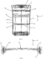
- the cross member 2 comprises two identical docking ends formed at its opposite longitudinal ends. This is particularly the case in Figures 7 and 8 where the sleepers 2a, 2b each have two docking ends 5a, 5b. In this case, along the longitudinal axis of the cross member 2 there is successively a first docking end 5a, a central section 15 of the crossbar 2 and a second docking end 5b. The first and second mating ends 5a, 5b are connected to each other by the central section 15 of the cross member 2. Each of the first and second mating ends 5a, 5b of the same cross member comprises in the direction of the central section 15 the three bearing surfaces 6, 7, 8 and the projecting element 13.
- each cross member 2 is intended to participate in the soundproofing of a roof liner 16.
- the docking ends 5a and 5b cooperate with hoops 1a, 1b participating in the delimitation of the passenger compartment.
- the arches 1a, 1b may comprise a stretcher liner or lining of longitudinal uprights and it is these liners that are approached by the crossbar 2.
- the invention also relates to an arrangement for a motor vehicle comprising at least a portion of a motor vehicle, in particular a roof horn 1a, 1b, on which is positioned a cross member 2 as described. Said arch 1a, 1b then forms the part of the motor vehicle on which the docking end is positioned.
- the arrangement comprises two vehicle parts subsequently identified as a first vehicle part 1a and a second vehicle part 1b.
- the first and second parts 1a, 1b of the vehicle are each accosted by a corresponding docking end 5a, 5b of the cross member 2.
- the first and second parts 1a, 1b of the vehicle may each comprise a reception fingerprint of the end of the vehicle.
- each of the docking ends are in contact with a corresponding edge of the first or second part 1a, 1b associated vehicle.
- the invention also relates to an assembly method for a motor vehicle comprising the following steps: providing a cross member 2 as described; providing the portion 1, 1a, 1b of a motor vehicle having a footprint corresponding to at least a portion of the docking end 5 of said cross member 2; positioning the docking end on the cavity, fixing the docking end 5 to the cavity at the first, second and third bearing surfaces 6, 7, 8, in particular by welding.
- the impression is such that it marries at least a portion of each bearing surface 6, 7, 8 when the cross member 2 is in the assembly position before the fixing step.
- the fixing step may be carried out via the use of welding tongs making at least one weld point between the cavity and the cross member 2 at each of the first, second and third bearing surfaces 6, 7, 8 .
- the positioning step comprises a step of placing the projecting element 13 relative to the cavity, in particular by a abutment of the projecting element 13 against an edge 14 of the impression.
- the forms adopted by the docking end allow the position of the crossbar before welding to be maintained with a tolerance of plus or minus 3 mm in particular along the X axis and the Y axis.
- the central section 15 has an omega section whose cavity is closed by a body member defining at least a portion of the roof horn.
Landscapes
- Engineering & Computer Science (AREA)
- Chemical & Material Sciences (AREA)
- Combustion & Propulsion (AREA)
- Transportation (AREA)
- Mechanical Engineering (AREA)
- Body Structure For Vehicles (AREA)
- Vehicle Step Arrangements And Article Storage (AREA)
Claims (9)
- Querträger (2), der so ausgelegt ist, dass er zur Schalldämpfung eines Kraftfahrzeugs beiträgt, wobei der schalldämpfende Querträger (2) mindestens ein Ankopplungsende (5) aufweist, das zur Montage des Querträgers (2) an einem entsprechenden Teil (1) des Kraftfahrzeugs vorgesehen ist, wobei das Ankopplungsende (5) eine erste, zweite und dritte separate Auflagefläche (6, 7, 8) aufweist, die den entsprechenden Teil (1) des Kraftfahrzeugs berühren sollen, wobei die zweite Auflagefläche (7) zwischen der ersten und dritten Auflagefläche (6, 8) auf einer anderen Höhe als die erste und dritte Auflagefläche (6, 8) angeordnet ist, dadurch gekennzeichnet, dass das Ankopplungsende (5) ein vorspringendes Element (13) aufweist, das zur Platzierung des Querträgers (2) bezogen auf den Teil (1) des Fahrzeugs in einer Längsachse des Querträgers (2) beitragen soll.
- Querträger nach dem vorhergehenden Anspruch, dadurch gekennzeichnet, dass die erste und dritte Auflagefläche (6, 8) jeweils ein unterschiedliches Höhenmaß nach einem Bezugssystem aufweisen, das durch die zweite Auflagefläche (7) vorgegeben ist.
- Querträger nach einem der vorhergehenden Ansprüche, dadurch gekennzeichnet, dass die erste Auflagefläche (6) in einer ersten Ebene (P1) enthalten ist, die zweite Auflagefläche (7) in einer zweiten Ebene (P2) enthalten ist und die dritte Auflagefläche (8) in einer dritten Ebene (P3) enthalten ist, wobei die erste Ebene (P1) zwischen der zweiten und dritten Ebene (P2, P3) angeordnet ist.
- Querträger nach einem der vorhergehenden Ansprüche, dadurch gekennzeichnet, dass das Ankopplungsende (5) einen mittigen Teil (9) aufweist, der die zweite Auflagefläche (7) abgrenzt und auf beiden Seiten mit einem ersten und zweiten Seitenschenkel (10, 11) des Ankopplungsendes (5), die die erste beziehungsweise dritte Auflagefläche (6, 8) abgrenzen, über Verbindungselemente (12a, 12b) verbunden ist, die vom ersten und zweiten Seitenschenkel (10, 11) aus in ein und derselben Richtung zum mittigen Teil (9) hin ausgerichtet verlaufen.
- Querträger nach dem vorhergehenden Anspruch, dadurch gekennzeichnet, dass der Querträger (2) in einem orthonormierten Bezugssystem aus den Achsen X, Y und Z längs in Richtung der Achse Y verläuft, der zweite Seitenschenkel (11), der mittige Teil (9) und der erste Seitenschenkel (10) in Richtung der Achse X hintereinander angeordnet sind, und die erste, zweite und dritte Fläche (6, 7, 8) in Richtung der Achse Z unterschiedliche Höhen aufweisen.
- Querträger nach einem der vorhergehenden Ansprüche, dadurch gekennzeichnet, dass er zwei identische Andockenden (5a, 5b) aufweist, die an seinen gegenüberliegenden Längsenden ausgebildet sind.
- Anordnung für Kraftfahrzeug, die mindestens einen Kraftfahrzeugteil aufweist, an dem ein Querträger nach einem der vorhergehenden Ansprüche platziert ist.
- Anordnung nach dem vorhergehenden Anspruch, dadurch gekennzeichnet, dass der mindestens eine Teil ein Dachhimmelbogen ist.
- Montageverfahren für Kraftfahrzeug, das folgende Schritte umfasst:- Bereitstellen eines Querträgers (2) nach einem der Ansprüche 1 bis 7,- Bereitstellen des Teils (1) des Kraftfahrzeugs, der eine Eindrückung aufweist, die zumindest einem Abschnitt des Ankopplungsendes (5, 5a, 5b) des Querträgers (2) entspricht,- Platzieren des Ankopplungsendes (5a, 5b, 5) auf der Eindrückung, Anordnen des vorspringenden Elements (13) bezogen auf die Eindrückung durch Anstoßen des vorspringenden Elements (13) gegen einen Rand (14) der Eindrückung,- Fixieren des Ankopplungsendes (5a, 5b, 5) an der Eindrückung im Bereich der ersten, zweiten und dritten Auflagefläche (6, 7, 8), insbesondere durch Schweißen.
Applications Claiming Priority (2)
| Application Number | Priority Date | Filing Date | Title |
|---|---|---|---|
| FR1460079A FR3027275B1 (fr) | 2014-10-20 | 2014-10-20 | Traverse destinee a participer a l'insonorisation d'un vehicule automobile |
| PCT/FR2015/052597 WO2016062934A1 (fr) | 2014-10-20 | 2015-09-29 | Traverse destinée à participer à l'insonorisation d'un véhicule automobile |
Publications (2)
| Publication Number | Publication Date |
|---|---|
| EP3209538A1 EP3209538A1 (de) | 2017-08-30 |
| EP3209538B1 true EP3209538B1 (de) | 2019-08-14 |
Family
ID=52450322
Family Applications (1)
| Application Number | Title | Priority Date | Filing Date |
|---|---|---|---|
| EP15781392.4A Active EP3209538B1 (de) | 2014-10-20 | 2015-09-29 | Querträger als beitrag zur schalldämpfung eines kraftfahrzeugs |
Country Status (5)
| Country | Link |
|---|---|
| EP (1) | EP3209538B1 (de) |
| BR (1) | BR112017007549B1 (de) |
| FR (1) | FR3027275B1 (de) |
| RU (1) | RU2696192C2 (de) |
| WO (1) | WO2016062934A1 (de) |
Family Cites Families (5)
| Publication number | Priority date | Publication date | Assignee | Title |
|---|---|---|---|---|
| JP2538907Y2 (ja) * | 1991-07-25 | 1997-06-18 | マツダ株式会社 | 車両の上部車体構造 |
| FR2921038B1 (fr) * | 2007-09-19 | 2010-01-01 | Peugeot Citroen Automobiles Sa | Structure de carrosserie de vehicule a jonction renforcee entre la traverse avant de pavillon et la doublure du montant de baie de pare-brise |
| US8371642B2 (en) * | 2010-12-24 | 2013-02-12 | Ford Global Technologies | Vehicle body structure |
| US8177292B1 (en) * | 2010-12-24 | 2012-05-15 | Ford Global Technologies | Vehicle structural arrangement for enhanced roof strength |
| FR2976234B1 (fr) * | 2011-06-10 | 2013-06-28 | Peugeot Citroen Automobiles Sa | Carrosserie de vehicule automobile, comprenant un pied milieu et un arceau central encastre dans le pied milieu. |
-
2014
- 2014-10-20 FR FR1460079A patent/FR3027275B1/fr not_active Expired - Fee Related
-
2015
- 2015-09-29 RU RU2017117362A patent/RU2696192C2/ru active
- 2015-09-29 BR BR112017007549-0A patent/BR112017007549B1/pt active IP Right Grant
- 2015-09-29 EP EP15781392.4A patent/EP3209538B1/de active Active
- 2015-09-29 WO PCT/FR2015/052597 patent/WO2016062934A1/fr active Application Filing
Non-Patent Citations (1)
| Title |
|---|
| None * |
Also Published As
| Publication number | Publication date |
|---|---|
| RU2017117362A (ru) | 2018-11-22 |
| WO2016062934A1 (fr) | 2016-04-28 |
| BR112017007549B1 (pt) | 2022-12-20 |
| FR3027275B1 (fr) | 2018-01-19 |
| EP3209538A1 (de) | 2017-08-30 |
| RU2017117362A3 (de) | 2019-03-20 |
| RU2696192C2 (ru) | 2019-07-31 |
| BR112017007549A2 (pt) | 2018-02-06 |
| FR3027275A1 (fr) | 2016-04-22 |
Similar Documents
| Publication | Publication Date | Title |
|---|---|---|
| EP2135775B1 (de) | Stoßstangenanordnung und entsprechendes Kraftfahrzeug | |
| EP2785576B1 (de) | Kraftfahrzeug mit einem oberen brandschottquerträger | |
| EP2744698B1 (de) | Kraftfahrzeugkarosserie mit einer versteifungsvorrichtung | |
| EP3126209B1 (de) | Verstärkte kraftfahrzeug struktur | |
| EP1693283B1 (de) | Vorderbau für ein Kraftfahrzeug | |
| FR3022520A1 (fr) | Plancher de vehicule automobile avec podium de renfort composite | |
| EP1819543B1 (de) | Türplattenversteifer | |
| EP3209538B1 (de) | Querträger als beitrag zur schalldämpfung eines kraftfahrzeugs | |
| WO2008090274A1 (fr) | Dispositif de liaison de deux éléments de structure de véhicule automobile | |
| EP3445641B1 (de) | Vorderflügelstruktur für kraftfahrzeug | |
| EP2262675B1 (de) | Verstärkte säule für ein motorfahrzeug | |
| FR2900896A1 (fr) | Element de liaison pour realiser un longeron, longeron comportant un tel element et vehicule automobile comportant au moins un tel longeron | |
| EP3154842B1 (de) | Vorderteil für die struktur eines kraftfahrzeugs | |
| FR3111615A1 (fr) | Renfort de liaison entre un pied avant de véhicule automobile et une ligne de brancard dudit véhicule automobile | |
| EP3863912B1 (de) | Im fall eines pfahlstosses verstärkte sitzbodenstruktur | |
| FR2882327A1 (fr) | Structure avant de vehicule automobile | |
| EP3405382A1 (de) | Teil zur verstärkung eines unteren querträgers für eine fensteröffnung | |
| EP3375697B1 (de) | A-säule eines fahrzeugs, die mit einer befestigungshalterung für eine querstrebe des armaturenbretts eines kraftfahrzeugs ausgestattet ist | |
| EP3339143B1 (de) | Anordnung für karosseriestruktur eines kraftfahrzeugs, die einen stossdämpfer umfasst | |
| EP3356206B1 (de) | Zur ermöglichung der befestigung von sitzen und zur verstärkung einer kraftfahrzeugkarosserie fähiges profilelement | |
| FR3124153A1 (fr) | Renfort destiné à être logé dans un longeron de véhicule automobile | |
| EP2844538B1 (de) | Träger der unterbodenstruktur eines kraftfahrzeugs sowie kraftfahrzeug mit solch einem träger | |
| WO2021064307A1 (fr) | Absorbeur de choc latéral pour véhicule automobile | |
| FR3135950A1 (fr) | colonne de direction pour véhicule automobile | |
| EP2925591B1 (de) | Aufbaustruktur für den kotflügel eines kraftfahrzeugs und kraftfahrzeug mit einer solchen aufbaustruktur |
Legal Events
| Date | Code | Title | Description |
|---|---|---|---|
| STAA | Information on the status of an ep patent application or granted ep patent |
Free format text: STATUS: THE INTERNATIONAL PUBLICATION HAS BEEN MADE |
|
| PUAI | Public reference made under article 153(3) epc to a published international application that has entered the european phase |
Free format text: ORIGINAL CODE: 0009012 |
|
| STAA | Information on the status of an ep patent application or granted ep patent |
Free format text: STATUS: REQUEST FOR EXAMINATION WAS MADE |
|
| 17P | Request for examination filed |
Effective date: 20170331 |
|
| AK | Designated contracting states |
Kind code of ref document: A1 Designated state(s): AL AT BE BG CH CY CZ DE DK EE ES FI FR GB GR HR HU IE IS IT LI LT LU LV MC MK MT NL NO PL PT RO RS SE SI SK SM TR |
|
| AX | Request for extension of the european patent |
Extension state: BA ME |
|
| DAV | Request for validation of the european patent (deleted) | ||
| DAX | Request for extension of the european patent (deleted) | ||
| GRAP | Despatch of communication of intention to grant a patent |
Free format text: ORIGINAL CODE: EPIDOSNIGR1 |
|
| STAA | Information on the status of an ep patent application or granted ep patent |
Free format text: STATUS: GRANT OF PATENT IS INTENDED |
|
| INTG | Intention to grant announced |
Effective date: 20180821 |
|
| GRAF | Information related to payment of grant fee modified |
Free format text: ORIGINAL CODE: EPIDOSCIGR3 |
|
| GRAS | Grant fee paid |
Free format text: ORIGINAL CODE: EPIDOSNIGR3 |
|
| GRAA | (expected) grant |
Free format text: ORIGINAL CODE: 0009210 |
|
| STAA | Information on the status of an ep patent application or granted ep patent |
Free format text: STATUS: THE PATENT HAS BEEN GRANTED |
|
| AK | Designated contracting states |
Kind code of ref document: B1 Designated state(s): AL AT BE BG CH CY CZ DE DK EE ES FI FR GB GR HR HU IE IS IT LI LT LU LV MC MK MT NL NO PL PT RO RS SE SI SK SM TR |
|
| REG | Reference to a national code |
Ref country code: GB Ref legal event code: FG4D Free format text: NOT ENGLISH |
|
| REG | Reference to a national code |
Ref country code: CH Ref legal event code: EP Ref country code: AT Ref legal event code: REF Ref document number: 1166687 Country of ref document: AT Kind code of ref document: T Effective date: 20190815 |
|
| REG | Reference to a national code |
Ref country code: DE Ref legal event code: R096 Ref document number: 602015035891 Country of ref document: DE |
|
| REG | Reference to a national code |
Ref country code: IE Ref legal event code: FG4D Free format text: LANGUAGE OF EP DOCUMENT: FRENCH |
|
| REG | Reference to a national code |
Ref country code: NL Ref legal event code: MP Effective date: 20190814 |
|
| REG | Reference to a national code |
Ref country code: LT Ref legal event code: MG4D |
|
| PG25 | Lapsed in a contracting state [announced via postgrant information from national office to epo] |
Ref country code: FI Free format text: LAPSE BECAUSE OF FAILURE TO SUBMIT A TRANSLATION OF THE DESCRIPTION OR TO PAY THE FEE WITHIN THE PRESCRIBED TIME-LIMIT Effective date: 20190814 Ref country code: NL Free format text: LAPSE BECAUSE OF FAILURE TO SUBMIT A TRANSLATION OF THE DESCRIPTION OR TO PAY THE FEE WITHIN THE PRESCRIBED TIME-LIMIT Effective date: 20190814 Ref country code: HR Free format text: LAPSE BECAUSE OF FAILURE TO SUBMIT A TRANSLATION OF THE DESCRIPTION OR TO PAY THE FEE WITHIN THE PRESCRIBED TIME-LIMIT Effective date: 20190814 Ref country code: LT Free format text: LAPSE BECAUSE OF FAILURE TO SUBMIT A TRANSLATION OF THE DESCRIPTION OR TO PAY THE FEE WITHIN THE PRESCRIBED TIME-LIMIT Effective date: 20190814 Ref country code: PT Free format text: LAPSE BECAUSE OF FAILURE TO SUBMIT A TRANSLATION OF THE DESCRIPTION OR TO PAY THE FEE WITHIN THE PRESCRIBED TIME-LIMIT Effective date: 20191216 Ref country code: SE Free format text: LAPSE BECAUSE OF FAILURE TO SUBMIT A TRANSLATION OF THE DESCRIPTION OR TO PAY THE FEE WITHIN THE PRESCRIBED TIME-LIMIT Effective date: 20190814 Ref country code: BG Free format text: LAPSE BECAUSE OF FAILURE TO SUBMIT A TRANSLATION OF THE DESCRIPTION OR TO PAY THE FEE WITHIN THE PRESCRIBED TIME-LIMIT Effective date: 20191114 Ref country code: NO Free format text: LAPSE BECAUSE OF FAILURE TO SUBMIT A TRANSLATION OF THE DESCRIPTION OR TO PAY THE FEE WITHIN THE PRESCRIBED TIME-LIMIT Effective date: 20191114 |
|
| REG | Reference to a national code |
Ref country code: AT Ref legal event code: MK05 Ref document number: 1166687 Country of ref document: AT Kind code of ref document: T Effective date: 20190814 |
|
| PG25 | Lapsed in a contracting state [announced via postgrant information from national office to epo] |
Ref country code: IS Free format text: LAPSE BECAUSE OF FAILURE TO SUBMIT A TRANSLATION OF THE DESCRIPTION OR TO PAY THE FEE WITHIN THE PRESCRIBED TIME-LIMIT Effective date: 20191214 Ref country code: ES Free format text: LAPSE BECAUSE OF FAILURE TO SUBMIT A TRANSLATION OF THE DESCRIPTION OR TO PAY THE FEE WITHIN THE PRESCRIBED TIME-LIMIT Effective date: 20190814 Ref country code: AL Free format text: LAPSE BECAUSE OF FAILURE TO SUBMIT A TRANSLATION OF THE DESCRIPTION OR TO PAY THE FEE WITHIN THE PRESCRIBED TIME-LIMIT Effective date: 20190814 Ref country code: RS Free format text: LAPSE BECAUSE OF FAILURE TO SUBMIT A TRANSLATION OF THE DESCRIPTION OR TO PAY THE FEE WITHIN THE PRESCRIBED TIME-LIMIT Effective date: 20190814 Ref country code: LV Free format text: LAPSE BECAUSE OF FAILURE TO SUBMIT A TRANSLATION OF THE DESCRIPTION OR TO PAY THE FEE WITHIN THE PRESCRIBED TIME-LIMIT Effective date: 20190814 Ref country code: GR Free format text: LAPSE BECAUSE OF FAILURE TO SUBMIT A TRANSLATION OF THE DESCRIPTION OR TO PAY THE FEE WITHIN THE PRESCRIBED TIME-LIMIT Effective date: 20191115 |
|
| PG25 | Lapsed in a contracting state [announced via postgrant information from national office to epo] |
Ref country code: PL Free format text: LAPSE BECAUSE OF FAILURE TO SUBMIT A TRANSLATION OF THE DESCRIPTION OR TO PAY THE FEE WITHIN THE PRESCRIBED TIME-LIMIT Effective date: 20190814 Ref country code: EE Free format text: LAPSE BECAUSE OF FAILURE TO SUBMIT A TRANSLATION OF THE DESCRIPTION OR TO PAY THE FEE WITHIN THE PRESCRIBED TIME-LIMIT Effective date: 20190814 Ref country code: DK Free format text: LAPSE BECAUSE OF FAILURE TO SUBMIT A TRANSLATION OF THE DESCRIPTION OR TO PAY THE FEE WITHIN THE PRESCRIBED TIME-LIMIT Effective date: 20190814 Ref country code: IT Free format text: LAPSE BECAUSE OF FAILURE TO SUBMIT A TRANSLATION OF THE DESCRIPTION OR TO PAY THE FEE WITHIN THE PRESCRIBED TIME-LIMIT Effective date: 20190814 Ref country code: AT Free format text: LAPSE BECAUSE OF FAILURE TO SUBMIT A TRANSLATION OF THE DESCRIPTION OR TO PAY THE FEE WITHIN THE PRESCRIBED TIME-LIMIT Effective date: 20190814 Ref country code: RO Free format text: LAPSE BECAUSE OF FAILURE TO SUBMIT A TRANSLATION OF THE DESCRIPTION OR TO PAY THE FEE WITHIN THE PRESCRIBED TIME-LIMIT Effective date: 20190814 |
|
| PG25 | Lapsed in a contracting state [announced via postgrant information from national office to epo] |
Ref country code: SM Free format text: LAPSE BECAUSE OF FAILURE TO SUBMIT A TRANSLATION OF THE DESCRIPTION OR TO PAY THE FEE WITHIN THE PRESCRIBED TIME-LIMIT Effective date: 20190814 Ref country code: IS Free format text: LAPSE BECAUSE OF FAILURE TO SUBMIT A TRANSLATION OF THE DESCRIPTION OR TO PAY THE FEE WITHIN THE PRESCRIBED TIME-LIMIT Effective date: 20200224 Ref country code: SK Free format text: LAPSE BECAUSE OF FAILURE TO SUBMIT A TRANSLATION OF THE DESCRIPTION OR TO PAY THE FEE WITHIN THE PRESCRIBED TIME-LIMIT Effective date: 20190814 Ref country code: MC Free format text: LAPSE BECAUSE OF FAILURE TO SUBMIT A TRANSLATION OF THE DESCRIPTION OR TO PAY THE FEE WITHIN THE PRESCRIBED TIME-LIMIT Effective date: 20190814 Ref country code: CZ Free format text: LAPSE BECAUSE OF FAILURE TO SUBMIT A TRANSLATION OF THE DESCRIPTION OR TO PAY THE FEE WITHIN THE PRESCRIBED TIME-LIMIT Effective date: 20190814 |
|
| REG | Reference to a national code |
Ref country code: CH Ref legal event code: PL |
|
| REG | Reference to a national code |
Ref country code: DE Ref legal event code: R097 Ref document number: 602015035891 Country of ref document: DE |
|
| PLBE | No opposition filed within time limit |
Free format text: ORIGINAL CODE: 0009261 |
|
| STAA | Information on the status of an ep patent application or granted ep patent |
Free format text: STATUS: NO OPPOSITION FILED WITHIN TIME LIMIT |
|
| PG2D | Information on lapse in contracting state deleted |
Ref country code: IS |
|
| PG25 | Lapsed in a contracting state [announced via postgrant information from national office to epo] |
Ref country code: LI Free format text: LAPSE BECAUSE OF NON-PAYMENT OF DUE FEES Effective date: 20190930 Ref country code: CH Free format text: LAPSE BECAUSE OF NON-PAYMENT OF DUE FEES Effective date: 20190930 Ref country code: LU Free format text: LAPSE BECAUSE OF NON-PAYMENT OF DUE FEES Effective date: 20190929 Ref country code: IE Free format text: LAPSE BECAUSE OF NON-PAYMENT OF DUE FEES Effective date: 20190929 |
|
| 26N | No opposition filed |
Effective date: 20200603 |
|
| REG | Reference to a national code |
Ref country code: BE Ref legal event code: MM Effective date: 20190930 |
|
| PG25 | Lapsed in a contracting state [announced via postgrant information from national office to epo] |
Ref country code: SI Free format text: LAPSE BECAUSE OF FAILURE TO SUBMIT A TRANSLATION OF THE DESCRIPTION OR TO PAY THE FEE WITHIN THE PRESCRIBED TIME-LIMIT Effective date: 20190814 Ref country code: BE Free format text: LAPSE BECAUSE OF NON-PAYMENT OF DUE FEES Effective date: 20190930 |
|
| GBPC | Gb: european patent ceased through non-payment of renewal fee |
Effective date: 20191114 |
|
| PG25 | Lapsed in a contracting state [announced via postgrant information from national office to epo] |
Ref country code: GB Free format text: LAPSE BECAUSE OF NON-PAYMENT OF DUE FEES Effective date: 20191114 |
|
| PG25 | Lapsed in a contracting state [announced via postgrant information from national office to epo] |
Ref country code: CY Free format text: LAPSE BECAUSE OF FAILURE TO SUBMIT A TRANSLATION OF THE DESCRIPTION OR TO PAY THE FEE WITHIN THE PRESCRIBED TIME-LIMIT Effective date: 20190814 |
|
| PG25 | Lapsed in a contracting state [announced via postgrant information from national office to epo] |
Ref country code: MT Free format text: LAPSE BECAUSE OF FAILURE TO SUBMIT A TRANSLATION OF THE DESCRIPTION OR TO PAY THE FEE WITHIN THE PRESCRIBED TIME-LIMIT Effective date: 20190814 Ref country code: HU Free format text: LAPSE BECAUSE OF FAILURE TO SUBMIT A TRANSLATION OF THE DESCRIPTION OR TO PAY THE FEE WITHIN THE PRESCRIBED TIME-LIMIT; INVALID AB INITIO Effective date: 20150929 |
|
| PG25 | Lapsed in a contracting state [announced via postgrant information from national office to epo] |
Ref country code: MK Free format text: LAPSE BECAUSE OF FAILURE TO SUBMIT A TRANSLATION OF THE DESCRIPTION OR TO PAY THE FEE WITHIN THE PRESCRIBED TIME-LIMIT Effective date: 20190814 |
|
| P01 | Opt-out of the competence of the unified patent court (upc) registered |
Effective date: 20230608 |
|
| PGFP | Annual fee paid to national office [announced via postgrant information from national office to epo] |
Ref country code: TR Payment date: 20230928 Year of fee payment: 9 |
|
| PGFP | Annual fee paid to national office [announced via postgrant information from national office to epo] |
Ref country code: FR Payment date: 20230928 Year of fee payment: 9 Ref country code: DE Payment date: 20230920 Year of fee payment: 9 |