EP3209489B1 - Vorrichtung und verfahren zur herstellung und reparatur von faserverstärkten verbundwerkstoffen - Google Patents
Vorrichtung und verfahren zur herstellung und reparatur von faserverstärkten verbundwerkstoffen Download PDFInfo
- Publication number
- EP3209489B1 EP3209489B1 EP15790192.7A EP15790192A EP3209489B1 EP 3209489 B1 EP3209489 B1 EP 3209489B1 EP 15790192 A EP15790192 A EP 15790192A EP 3209489 B1 EP3209489 B1 EP 3209489B1
- Authority
- EP
- European Patent Office
- Prior art keywords
- resin
- sheet
- infusion
- region
- retaining
- Prior art date
- Legal status (The legal status is an assumption and is not a legal conclusion. Google has not performed a legal analysis and makes no representation as to the accuracy of the status listed.)
- Active
Links
Images


Classifications
-
- B—PERFORMING OPERATIONS; TRANSPORTING
- B29—WORKING OF PLASTICS; WORKING OF SUBSTANCES IN A PLASTIC STATE IN GENERAL
- B29C—SHAPING OR JOINING OF PLASTICS; SHAPING OF MATERIAL IN A PLASTIC STATE, NOT OTHERWISE PROVIDED FOR; AFTER-TREATMENT OF THE SHAPED PRODUCTS, e.g. REPAIRING
- B29C70/00—Shaping composites, i.e. plastics material comprising reinforcements, fillers or preformed parts, e.g. inserts
- B29C70/04—Shaping composites, i.e. plastics material comprising reinforcements, fillers or preformed parts, e.g. inserts comprising reinforcements only, e.g. self-reinforcing plastics
- B29C70/28—Shaping operations therefor
- B29C70/40—Shaping or impregnating by compression not applied
- B29C70/42—Shaping or impregnating by compression not applied for producing articles of definite length, i.e. discrete articles
-
- B—PERFORMING OPERATIONS; TRANSPORTING
- B29—WORKING OF PLASTICS; WORKING OF SUBSTANCES IN A PLASTIC STATE IN GENERAL
- B29C—SHAPING OR JOINING OF PLASTICS; SHAPING OF MATERIAL IN A PLASTIC STATE, NOT OTHERWISE PROVIDED FOR; AFTER-TREATMENT OF THE SHAPED PRODUCTS, e.g. REPAIRING
- B29C73/00—Repairing of articles made from plastics or substances in a plastic state, e.g. of articles shaped or produced by using techniques covered by this subclass or subclass B29D
- B29C73/02—Repairing of articles made from plastics or substances in a plastic state, e.g. of articles shaped or produced by using techniques covered by this subclass or subclass B29D using liquid or paste-like material
- B29C73/025—Repairing of articles made from plastics or substances in a plastic state, e.g. of articles shaped or produced by using techniques covered by this subclass or subclass B29D using liquid or paste-like material fed under pressure
-
- B—PERFORMING OPERATIONS; TRANSPORTING
- B29—WORKING OF PLASTICS; WORKING OF SUBSTANCES IN A PLASTIC STATE IN GENERAL
- B29C—SHAPING OR JOINING OF PLASTICS; SHAPING OF MATERIAL IN A PLASTIC STATE, NOT OTHERWISE PROVIDED FOR; AFTER-TREATMENT OF THE SHAPED PRODUCTS, e.g. REPAIRING
- B29C70/00—Shaping composites, i.e. plastics material comprising reinforcements, fillers or preformed parts, e.g. inserts
- B29C70/04—Shaping composites, i.e. plastics material comprising reinforcements, fillers or preformed parts, e.g. inserts comprising reinforcements only, e.g. self-reinforcing plastics
- B29C70/28—Shaping operations therefor
- B29C70/40—Shaping or impregnating by compression not applied
- B29C70/42—Shaping or impregnating by compression not applied for producing articles of definite length, i.e. discrete articles
- B29C70/44—Shaping or impregnating by compression not applied for producing articles of definite length, i.e. discrete articles using isostatic pressure, e.g. pressure difference-moulding, vacuum bag-moulding, autoclave-moulding or expanding rubber-moulding
- B29C70/443—Shaping or impregnating by compression not applied for producing articles of definite length, i.e. discrete articles using isostatic pressure, e.g. pressure difference-moulding, vacuum bag-moulding, autoclave-moulding or expanding rubber-moulding and impregnating by vacuum or injection
-
- B—PERFORMING OPERATIONS; TRANSPORTING
- B29—WORKING OF PLASTICS; WORKING OF SUBSTANCES IN A PLASTIC STATE IN GENERAL
- B29C—SHAPING OR JOINING OF PLASTICS; SHAPING OF MATERIAL IN A PLASTIC STATE, NOT OTHERWISE PROVIDED FOR; AFTER-TREATMENT OF THE SHAPED PRODUCTS, e.g. REPAIRING
- B29C70/00—Shaping composites, i.e. plastics material comprising reinforcements, fillers or preformed parts, e.g. inserts
- B29C70/04—Shaping composites, i.e. plastics material comprising reinforcements, fillers or preformed parts, e.g. inserts comprising reinforcements only, e.g. self-reinforcing plastics
- B29C70/28—Shaping operations therefor
- B29C70/40—Shaping or impregnating by compression not applied
- B29C70/42—Shaping or impregnating by compression not applied for producing articles of definite length, i.e. discrete articles
- B29C70/46—Shaping or impregnating by compression not applied for producing articles of definite length, i.e. discrete articles using matched moulds, e.g. for deforming sheet moulding compounds [SMC] or prepregs
- B29C70/48—Shaping or impregnating by compression not applied for producing articles of definite length, i.e. discrete articles using matched moulds, e.g. for deforming sheet moulding compounds [SMC] or prepregs and impregnating the reinforcements in the closed mould, e.g. resin transfer moulding [RTM], e.g. by vacuum
-
- B—PERFORMING OPERATIONS; TRANSPORTING
- B29—WORKING OF PLASTICS; WORKING OF SUBSTANCES IN A PLASTIC STATE IN GENERAL
- B29C—SHAPING OR JOINING OF PLASTICS; SHAPING OF MATERIAL IN A PLASTIC STATE, NOT OTHERWISE PROVIDED FOR; AFTER-TREATMENT OF THE SHAPED PRODUCTS, e.g. REPAIRING
- B29C73/00—Repairing of articles made from plastics or substances in a plastic state, e.g. of articles shaped or produced by using techniques covered by this subclass or subclass B29D
- B29C73/02—Repairing of articles made from plastics or substances in a plastic state, e.g. of articles shaped or produced by using techniques covered by this subclass or subclass B29D using liquid or paste-like material
-
- B—PERFORMING OPERATIONS; TRANSPORTING
- B29—WORKING OF PLASTICS; WORKING OF SUBSTANCES IN A PLASTIC STATE IN GENERAL
- B29C—SHAPING OR JOINING OF PLASTICS; SHAPING OF MATERIAL IN A PLASTIC STATE, NOT OTHERWISE PROVIDED FOR; AFTER-TREATMENT OF THE SHAPED PRODUCTS, e.g. REPAIRING
- B29C73/00—Repairing of articles made from plastics or substances in a plastic state, e.g. of articles shaped or produced by using techniques covered by this subclass or subclass B29D
- B29C73/04—Repairing of articles made from plastics or substances in a plastic state, e.g. of articles shaped or produced by using techniques covered by this subclass or subclass B29D using preformed elements
- B29C73/10—Repairing of articles made from plastics or substances in a plastic state, e.g. of articles shaped or produced by using techniques covered by this subclass or subclass B29D using preformed elements using patches sealing on the surface of the article
-
- B—PERFORMING OPERATIONS; TRANSPORTING
- B29—WORKING OF PLASTICS; WORKING OF SUBSTANCES IN A PLASTIC STATE IN GENERAL
- B29K—INDEXING SCHEME ASSOCIATED WITH SUBCLASSES B29B, B29C OR B29D, RELATING TO MOULDING MATERIALS OR TO MATERIALS FOR MOULDS, REINFORCEMENTS, FILLERS OR PREFORMED PARTS, e.g. INSERTS
- B29K2063/00—Use of EP, i.e. epoxy resins or derivatives thereof, as moulding material
-
- B—PERFORMING OPERATIONS; TRANSPORTING
- B29—WORKING OF PLASTICS; WORKING OF SUBSTANCES IN A PLASTIC STATE IN GENERAL
- B29K—INDEXING SCHEME ASSOCIATED WITH SUBCLASSES B29B, B29C OR B29D, RELATING TO MOULDING MATERIALS OR TO MATERIALS FOR MOULDS, REINFORCEMENTS, FILLERS OR PREFORMED PARTS, e.g. INSERTS
- B29K2105/00—Condition, form or state of moulded material or of the material to be shaped
- B29K2105/06—Condition, form or state of moulded material or of the material to be shaped containing reinforcements, fillers or inserts
- B29K2105/08—Condition, form or state of moulded material or of the material to be shaped containing reinforcements, fillers or inserts of continuous length, e.g. cords, rovings, mats, fabrics, strands or yarns
- B29K2105/0872—Prepregs
-
- B—PERFORMING OPERATIONS; TRANSPORTING
- B29—WORKING OF PLASTICS; WORKING OF SUBSTANCES IN A PLASTIC STATE IN GENERAL
- B29K—INDEXING SCHEME ASSOCIATED WITH SUBCLASSES B29B, B29C OR B29D, RELATING TO MOULDING MATERIALS OR TO MATERIALS FOR MOULDS, REINFORCEMENTS, FILLERS OR PREFORMED PARTS, e.g. INSERTS
- B29K2307/00—Use of elements other than metals as reinforcement
- B29K2307/04—Carbon
Definitions
- the disclosure relates generally to composite parts comprising fibre-reinforced structures, and more particularly manufacturing and repairing composite parts by resin infusion.
- Resin infusion processes such as resin transfer infusion (RTI), resin transfer molding (RTM), vacuum-assisted resin transfer molding (VARTM), vacuum-assisted resin infusion (VARI) and Seemann composites resin infusion molding process (SCRIMP) are known processes used for manufacturing composite parts comprising fibre-reinforced structures. Occasionally and depending on factors associated with such infusion processes, there can be dry fabric patches at the surface of fibre-reinforced parts that were not completely impregnated with resin during the process. A conventional procedure for repairing such dry fabric patches is to apply a cosmetic resin wipe. However, this repair procedure is mainly cosmetic (i.e. non-structural) in nature and can result in the presence of structural defects such as porosity in the repaired region of the part due to air being trapped in the repaired region during the procedure.
- RTI resin transfer infusion
- RTM resin transfer molding
- VARTM vacuum-assisted resin transfer molding
- VARI vacuum-assisted resin infusion
- SCRIMP Seemann composites resin infusion molding process
- the disclosure describes a device for retaining and controlling the release of resin during a resin infusion process for manufacturing or repairing fibre-reinforced composite materials.
- the resin retaining/releasing device comprises:
- the first sheet is substantially resin-impermeable when the viscosity of the resin is below the threshold viscosity.
- the first sheet may comprise a plurality of pores sized to permit passage of gas through the first sheet and to prevent the passage of resin through the first sheet when the viscosity of the resin is below the threshold viscosity.
- the second sheet may comprise a plurality of pores sized to permit passage of gas through the second sheet and to permit the passage of resin through the second sheet when the viscosity of the resin is below the threshold viscosity.
- At least one of the first sheet and the second sheet comprises a first layer including a woven fabric and a second layer comprising a porous, preferably polytetrafluoroethylene (PTFE), membrane.
- the PTFE membrane of the first layer may face the resin.
- the first sheet and the second sheet may be at least partially sealed to each other.
- the first sheet may be resin-permeable when the viscosity of the resin is below the threshold viscosity.
- the resin may comprise a one-part liquid epoxy.
- the threshold viscosity may be about 50 centipoise.
- the disclosure describes an apparatus for manufacturing or repairing fibre-reinforced composite materials.
- the apparatus comprises:
- the quantity of resin may be laterally offset from the infusion region.
- the vacuum port may be laterally offset from the infusion region in a lateral direction opposite that of the quantity of resin from the infusion region.
- the quantity of resin may be disposed alongside the infusion region.
- the apparatus may comprise a resin distribution mesh forming part of the infusion path between the resin and the infusion region.
- the apparatus may comprise a release medium disposed between the resin retaining/releasing device and the distribution mesh.
- the apparatus may comprise a release medium disposed between the resin retaining/releasing device and the infusion region.
- the heater may comprise a heating blanket covering at least part of the resin retaining/releasing device and at least part of the infusion region.
- the heater may comprise a heating blanket disposed between the resin retaining/releasing device and the infusion region.
- the heating blanket may comprise an infusion hole therethrough forming at least part of the infusion path.
- the apparatus may comprise a first breather disposed in the volume between the resin retaining/releasing device and the vacuum barrier.
- the vacuum barrier may be a first vacuum barrier
- the volume may be a first volume
- the vacuum port may be a first vacuum port
- the apparatus may comprise:
- At least part of the heater may be disposed in the second volume between the second vacuum barrier and the first vacuum barrier.
- the apparatus may comprise a second breather disposed in the second volume between the second vacuum barrier and the first vacuum barrier.
- the heater may comprise a first heating blanket for heating the resin retaining/releasing device and a second heating blanket for heating the infusion region.
- the first heating blanket may be disposed on a first side of the infusion region and the second heating blanket may be disposed on an opposite second side of the infusion region.
- the first heating blanket may be disposed between the resin retaining/releasing device and the part.
- the heating blanket may comprise an infusion hole therethrough forming at least part of the infusion path.
- the heater may be configured to apply heat to the infusion region of the part.
- the first sheet of the resin retaining/releasing device is substantially resin-impermeable when the viscosity of the resin is below the threshold viscosity.
- the first sheet of the resin retaining/releasing device may comprise a plurality of pores sized to permit passage of gas through the first sheet and to prevent the passage of resin through the first sheet when the viscosity of the resin is below the threshold viscosity.
- the second sheet of the resin retaining/releasing device may comprise a plurality of pores sized to permit passage of gas through the second sheet and to permit the passage of resin through the second sheet when the viscosity of the resin is below the threshold viscosity.
- At least one of the first sheet and the second sheet of the resin retaining/releasing device comprises a first layer including a woven fabric and a second layer comprising a porous, preferably polytetrafluoroethylene (PTFE), membrane.
- PTFE polytetrafluoroethylene
- the PTFE membrane of the first layer may face the resin.
- the first sheet and the second sheet may be at least partially sealed to each other.
- the first sheet is resin-permeable when the viscosity of the resin is below the threshold viscosity.
- the resin may comprise a one-part liquid epoxy.
- the threshold viscosity is about 50 centipoise.
- the first breather may comprise a woven fabric.
- the woven fabric may be part of a multi-layer membrane system, which may also comprise a porous polytetrafluoroethylene (PTFE) membrane.
- PTFE polytetrafluoroethylene
- the disclosure describes a method useful for manufacturing or repairing fibre-reinforced composite materials using a device for retaining and controlling the release of resin where the resin retaining/releasing device comprises a first sheet and an opposite second sheet at least partially enclosing a quantity of resin having a viscosity that is temperature dependent.
- the method comprises:
- the evacuation of the gas may be performed during the infusion of the resin into the infusion region.
- the evacuation of the gas may be performed after the infusion of the resin into the infusion region.
- the quantity of resin may be laterally offset from the infusion region and the method may comprise directing the resin toward the infusion region.
- the method may comprise applying a force on the resin to cause the resin having reached the threshold viscosity to permeate through the second sheet.
- the quantity of resin may be disposed alongside the infusion region.
- the method may comprise applying heat to the infusion region.
- the method may comprise applying heat from a first side of the infusion region and from an opposite second side of the infusion region.
- the resin may comprise a one-part liquid epoxy.
- the threshold viscosity may be about 50 mPa s (centipoise).
- the infusion region may comprise dry fabric.
- the infusion region may comprise a scarfed region.
- the infusion region may comprise a hole with dry fibres therein.
- the infusion region may comprise dry fabric plies.
- the infusion region may comprise a double-sided scarfed region.
- the method may comprise evacuating gas from a substantially sealed second volume enclosing the substantially sealed first volume.
- the method may comprise directing the resin having reached the threshold viscosity to permeate through a hole in a heater blanket and flow from the resin retaining/releasing device to the infusion region.
- the infusion region may comprise a dry fabric patch.
- the method may comprise directing the resin through a pilot hole formed in the infusion region.
- the disclosure describes an apparatus for manufacturing or repairing fibre-reinforced composite materials.
- the apparatus comprises:
- the quantity of resin may be laterally offset from the infusion region.
- the heater may comprise a heating blanket covering at least part of the resin retaining/releasing device and at least part of the infusion region.
- the sheet of the resin retaining/releasing device comprises a first layer including a woven fabric and a second layer comprising a porous, preferably polytetrafluoroethylene (PTFE), membrane.
- PTFE polytetrafluoroethylene
- the PTFE membrane of the first layer may face the resin.
- the present disclosure relates to apparatus and methods for manufacturing and/or repairing parts of composite materials comprising fibre-reinforced structures (e.g., containing carbon, quartz glass, e-glass and/or other fibres) by resin infusion.
- apparatus and methods disclosed herein may be used to repair parts that have been manufactured by resin infusion processes such as resin transfer infusion (RTI), resin transfer molding (RTM), vacuum-assisted resin transfer molding (VARTM), vacuum-assisted resin infusion (VARI) and Seemann composites resin infusion molding process (SCRIMP) for example.
- resin infusion processes such as resin transfer infusion (RTI), resin transfer molding (RTM), vacuum-assisted resin transfer molding (VARTM), vacuum-assisted resin infusion (VARI) and Seemann composites resin infusion molding process (SCRIMP) for example.
- Such parts may include parts for use in aerospace or other applications, such as for wind turbines, radomes or automotive parts.
- such parts may include aircraft parts such as fuselage and wing components such as spars, skins and also nacelle components for aircraft engines.
- the apparatus and methods disclosed herein may be used to repair regions of composite parts that have not been completely impregnated with resin during manufacturing or that have been damaged.
- the apparatus and methods disclosed herein may be used to infuse resin into dry fabric patches at the surface of composite parts.
- the apparatus and methods disclosed herein may also be used for manufacturing new parts comprising fibre-reinforced structures by resin infusion.
- the resin infusion referenced herein may comprise transferring resin from a resin retaining/releasing device incorporated into the layup of a resin transfer apparatus.
- the use of such resin retaining/releasing device in the apparatus and methods disclosed herein may improve the evacuation of gas (e.g., air and volatiles) from the region to be infused and thereby reduce the risk of obtaining porosity due to trapped gas (e.g., air) or voids due to insufficient resin quantity in the resin-infused region.
- gas e.g., air and volatiles
- FIG. 1 shows a non-destructive inspection (NDI) micrograph obtained by X-ray computed tomography (CT) a cross-section of region 10 of a composite part comprising porosity/voids.
- NDI non-destructive inspection
- CT X-ray computed tomography
- a repair may be carried out using a conventional cosmetic resin wipe procedure.
- Such procedure may comprise abrading the area, applying resin over the area, covering the area with a release film and a rubber sheet, vacuum bagging the area, allowing the resin to cure and subsequently abrading the area to the desired surface profile or surface finish if necessary.
- the conventional resin wipe process may be used to add resin to a dry fabric patch.
- FIGS. 2A-2D respectively show higher magnification NDI micrographs at four locations within region 10 of the composite part of FIG. 1.
- FIGS. 2A-2D show interstitial porosity between fibres and also between strands of the fabric in the composite material of region 10.
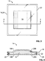
- FIG. 3 is a schematic top plan view of an exemplary device 14 for retaining and controlling the release of resin (referred hereinafter as "resin retaining/releasing device 14") and which may be used with the apparatus and methods disclosed herein for manufacturing and/or repairing composite materials by resin infusion.
- resin retaining/releasing device 14 in conjunction with the apparatus and methods disclosed herein may reduce the risk of obtaining porosity due to trapped gas (e.g., air) in composite materials as shown in FIGS. 1 and 2A-2D .
- resin retaining/releasing device 14 may improve the ability to evacuate gas/air from a region being infused with resin 16.
- FIG. 4 is a schematic cross-sectional view of resin retaining/releasing device 14 of FIG. 3 taken along line 4-4 in FIG. 3 .
- resin retaining/releasing device 14 may have a packet/pouch structure.
- resin retaining/releasing device 14 may contain a quantity of resin 16 having a viscosity that is temperature dependent.
- resin 16 may comprise a one-part liquid epoxy.
- resin 16 may be of the type sold under the trade name CYCOM 890 by CYTEC ENGINEERED MATERIALS.
- resin 16 may be of the type sold under the trade name HEXFLOW RTM 6 by HEXCEL.
- resin 16 may be of the type HYSOL ® EA9396 by HENKEL. In some embodiments, resin 16 may be of the type commonly known as "wipe resin”. Other types of cosmetic or structural resins may also be suitable for being part of resin retaining/releasing device 14 and used in the apparatus and methods disclosed herein.
- Resin retaining/releasing device 14 may comprise first sheet 18 and opposite second sheet 20 at least partially enclosing the quantity of resin 16.
- Second sheet 20 may be gas-permeable at temperatures typically encountered in the infusion process so that during a repair or manufacturing procedure using resin retaining/releasing device 14, gas (e.g., air) may be evacuated from resin 16 and/or from the infusion region of the composite part through second sheet 20.
- First sheet 18 may be gas impermeable.
- first sheet 18 may be resin permeable and gas-permeable at temperatures typically encountered in the infusion process so that during a repair or manufacturing procedure using resin retaining/releasing device 14, gas (e.g., air) may be evacuated from resin 16 and/or from infusion region 32 of composite part 34 through both first sheet 18 and second sheet 20.
- Second sheet 20 may be substantially resin-impermeable when the viscosity of resin 16 is above a threshold viscosity and/or below a pre-determined threshold temperature, and, resin-permeable when the viscosity of resin 16 is below the threshold viscosity and/or above the pre-determined threshold temperature.
- first sheet 18 and second sheet 20 may be attached to each other to contain resin 16 therebetween.
- first sheet and second sheet may be seamlessly attached together so as to form a bag with an opening for receiving the resin 16.
- first sheet 18 and second sheet 20 may be attached together using a suitable adhesive such as double-sided tape 22.
- Double-sided tape 22 may be selected to withstand temperatures at which resin retaining/releasing device 14 is exposed during use.
- double-sided tape 22 may be capable of withstanding temperatures of up to 180°C.
- Double-sided tape 22 may be considered to provide an at least partial sealing interface between first sheet 18 and second sheet 20. Such sealing interface may not be absolutely hermetic but may substantially prevent resin 16 from flowing out of resin retaining/releasing device 14 at least at some temperatures/viscosities of resin 16.
- double-sided tape 22 may allow resin 16 to be substantially contained within resin retaining/releasing device 14 during handling of resin retaining/releasing device 14 prior to use in a resin infusion process as described herein.
- first sheet 18 and second sheet 20 may not necessarily be attached nor sealingly engaged to each other.
- First sheet 18 may be of similar or identical construction to second sheet 20. Alternatively, first sheet 18 may be of different construction to second sheet 20.
- first sheet 18 may be substantially resin-impermeable when the viscosity of resin 16 is below the threshold viscosity, or, first sheet 18 may also be resin-permeable when the viscosity of resin 16 is below the threshold viscosity.
- first sheet 18 may comprise a membrane system according to product number A2222 or Z2249 by TRANS-TEXTIL.
- second sheet 18 may comprise a membrane system according to product number Z2249 by TRANS-TEXTIL.
- First sheet 18 and/or second sheet 20 may respectively comprises first layer 18A, 20A which may include a woven fabric and second layer 18B, 20B which may comprise a porous membrane.
- First layer 18A, 20A may be bonded to second layer 18B, 20B so that one or both of first sheet 18 and second sheet 20 may cooperate together to form a membrane system.
- the porous membrane of second layer 18B, 20B may face resin 16 and the woven fabric of first layer 18A, 20A may face outwardly from resin 16.
- the woven fabric of first layer 18A, 20A may face resin 16 and the porous membrane of second layer 18B, 20B may face outwardly from resin 16.
- the woven fabric of first layer 18A, 20A may be gas permeable.
- the woven fabric may also be resin-permeable at least when the viscosity of resin 16 is below the threshold viscosity.
- the porous membrane of second layer 18B, 20B may comprise a porous polytetrafluoroethylene (PTFE) membrane.
- PTFE polytetrafluoroethylene
- porous membrane of second layer 18B, 20B may comprise a microporous PTFE membrane.
- FIG. 5 is a schematic representation of an exemplary first and/or second sheet 18, 20 of resin retaining/releasing device 14 illustrating first layer 18A, 20A and second layer 18B, 20B adjoining each other.
- FIGS. 6A and 6B are magnified photographs of an exemplary woven fabric which may be part of first layer 18A, 20A of first sheet 18 and/or second sheet 20.
- the magnification in FIG. 6B is higher than that of FIG. 6A.
- FIG. 6A shows a plan view of the woven fabric that may comprise a plurality of tows made up of polyester filaments 24.
- FIG. 6B shows a cross-sectional view of one tow comprising individual filaments 24 bunched together.
- the woven fabric may have a relatively tight weave with relatively small spaces between individual filaments 24 to permit gas and/or resin 16 of relatively low viscosity to permeate through the woven fabric of first layer 18A, 20A.
- FIGS. 7A and 7B are magnified photographs of an exemplary PTFE membrane which may be part of second layer 18B, 20B of first sheet 18 and/or second sheet 20.
- PTFE membrane may comprise a PTFE alloy.
- PTFE membrane may comprise an expanded PTFE material also known as ePTFE.
- the magnification in FIG. 7B is higher than that of FIG. 7A .
- the PTFE membrane of second layer 18B, 20B may be porous.
- PTFE membrane of second layer 18B, 20B may comprise a plurality of pores 25 sized according to known or other methods (e.g., based on the surface tension of resin 16) to permit passage of gas through the PTFE membrane and to prevent the passage of resin 16 through the PTFE membrane when the viscosity of resin 16 is above the threshold viscosity.
- Pores 25 in the PTFE membrane are relatively small and cannot be clearly shown in FIGS. 7A and 7B due to insufficient magnification. Nevertheless, exemplary pores 25 are shown schematically and not to scale in FIG. 7B for illustration purpose.
- FIGS. 7A and 7B also show a plurality of thinned or otherwise weakened regions 26 that are distributed across the PTFE membrane of second layer 18B, 20B. Weakened regions 26 are shown as translucent areas in FIGS. 7A and 7B .
- the PTFE membrane may also be heated and weakened regions 26 may soften and thereby cause at least some of pores 25 in the PTFE membrane to also soften (i.e., become less rigid) and expand to a size allowing resin 16 to permeate the PTFE membrane when the viscosity of resin 16 has reached or dropped below a certain threshold due to heating of resin 16.
- PTFE membrane may be configured so that the expansion of pores 25 to a size suitable for allowing resin 16 at the desired viscosity to permeate the PTFE membrane occurs at a pre-determined temperature.
- PTFE membrane may not necessarily include such weakened regions 26 but may instead comprise pores 25 that are appropriately sized to achieve similar results.
- the PTFE membrane of second layer 18B, 20B may comprise a plurality of pores 25 sized to permit passage of gas through first sheet 18 and/or second sheet 20 and also permit the passage of resin 16 through first sheet 18 and/or second sheet 20 when the viscosity of resin 16 is below the threshold viscosity.
- the threshold viscosity and optionally the temperature of resin 16 reached during a resin infusion process may be used as a basis for selecting a suitable (e.g., pore size in) first sheet 18 and/or second sheet 20.
- the threshold viscosity and the temperature of resin 16 may be selected based on the specific application and process parameters. For example, the pore size may be selected based on the desired viscosity and flow rate of resin 16 during infusion.
- the threshold viscosity below which resin 16 may permeate through first sheet 18 and/or second sheet 20 may be about 50 mPa s (centipoise).
- the temperature at which the threshold viscosity may be achieved may be at about 140°C.
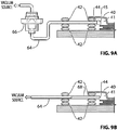
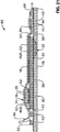
- FIG. 8A shows a schematic, cross-sectional view of an exemplary apparatus 30 for infusing resin 16 into region 32 (referred hereinafter as "infusion region 32") of a part 34 comprising a fibre-reinforced structure by infusion of resin 16.
- Apparatus 30 may comprise resin retaining/releasing device 14 as described above.
- Infusion region 32 may comprise a damaged region of part 34 or a patch of dry fabric that was not sufficiently impregnated with resin during manufacturing.
- apparatus 30 may be used to manufacture a new part 34 or a portion thereof where infusion region 32 may comprise a woven fabric or other filaments (e.g., fibres) that may serve as a substrate for a new manufactured part.
- infusion region 32 may comprise one or more constituents of a composite material to be impregnated with resin 16 from resin retaining/releasing device 14.
- Such constituent may, for example, comprise quartz glass, e-glass and/or carbon fibres, carbon black, carbon nano tubes and/or graphene.
- a suitable release medium 38 may be disposed above region 32.
- Release medium 38 may include various varieties of oils, greases, and other polymers having relatively low strength.
- release medium 38 may comprise a cohesively formed plastic that does not readily adhere to other polymers or other type of known or other release medium.
- release medium 38 may be configured to not chemically bond to the part 34 so that it may be easily removed by peeling after resin infusion.
- release medium 38 may comprise a PTFE coated fibreglass fabric of the type sold under the trade name RELEASE EASE ® by AIRTECH.
- apparatus 30 may comprise first (e.g., inner) vacuum barrier 40 configured to cover infusion region 32 of part 34 and to be substantially sealingly engaged to part 34 around infusion region 32 of part 34 to define a first volume 41 between first vacuum barrier 40 and part 34. Disposed within first volume 41 is the resin retaining/releasing device 14. Sealing between first vacuum barrier 40 and part 34 may be achieved via one or more suitable sealing members 42.
- First vacuum barrier 40 may comprise a suitable polymer (e.g., nylon) flexible sheet and may be of the type(s) typically used as flexible bagging membranes (i.e., vacuum bags) in known or other resin infusion processes. Vacuum barrier 40 may be substantially gas-impermeable.
- sealing members 42 may comprise a suitable sealant or double-sided tape. Sealing between first vacuum barrier 40 and part 34 may not be absolutely hermetic but may be suitable for achieving at least some differential pressure (e.g., a residual pressure of 3 millibars) between first volume 41 and the atmosphere.
- vacuum barrier 40 may be of the same material as first sheet 18 and/or second sheet 20 of resin retaining/releasing device 14.
- Apparatus 30 may comprise first vacuum port 44 for fluid communication with first volume 41.
- Vacuum port 44 may be coupled to a vacuum source (shown in FIGS. 9A and 9B ) that may be used to evacuate gas/air from first volume 41 prior, during and/or after the transfer of resin 16 to infusion region 32.
- Vacuum port 44 may be located in a relatively low temperature zone away from infusion region 32.
- vacuum port 44 may be located in a region where the temperature is typically lower than 120 °C even during curing of resin 16 in infusion region 32.
- vacuum port 44 may be located in a region where the temperature does not significantly exceed room/ambient temperatures. Accordingly, resin 16 may not typically flow to vacuum port 44.
- vacuum port 44 may be covered by a suitable barrier 45 to prevent resin 16 from entering vacuum port 44.
- barrier 45 may be of the same material as first sheet 18 and/or second sheet 20 of resin retaining/releasing device 14. Evacuation of first volume 41 via first vacuum port 44 may cause at least some the air and moisture to be evacuated from infusion region 32 and also from resin 16 and may reduce the likelihood of porosity being formed in infusion region 32 as a result of the infusion of resin 16.
- Apparatus 30 may comprise resin retaining/releasing device 14 as described above disposed inside first volume 41 and part of the layup of apparatus 30.
- Resin retaining/releasing device 14 may comprise a quantity of resin 16 having a viscosity that is temperature dependent.
- Resin retaining/releasing device 14 may comprise first sheet 18 and opposite second sheet 20 at least partially enclosing the quantity of resin 16.
- First sheet 18 and second sheet 20 may be gas-permeable.
- Second sheet 20 may be substantially resin-impermeable when the viscosity of resin 16 is above a threshold viscosity and resin-permeable when the viscosity of resin 16 is below the threshold viscosity.
- Second sheet 20 of resin retaining/releasing device 14 may form at least part of an infusion path between resin 16 and infusion region 32.
- Apparatus 30 may also comprise heater 46 configured to apply heat to resin 16.
- Heater 46 may comprise one or more electrically-powered heating blankets or other means suitable to transfer heat to resin 16 and/or infusion region 32.
- heating blanket(s) 46 may cover at least part of resin retaining/releasing device 14 and/or at least part of infusion region 32.
- Heating blanket(s) 46 may be disposed outside of first volume 41.
- heating blanket(s) 46 may be disposed outside of and against first vacuum barrier 40 and overlay at least part of the layup of components in first volume 41.
- Apparatus 30 may also comprise distribution mesh 48 forming part of the infusion path between resin 16 and infusion region 32.
- Distribution mesh 48 may assist in causing resin 16 to be distributed (i.e., spread) over and infused into infusion region 32 once at least some of resin 16 has reached a temperature where the viscosity of resin 16 is below the threshold viscosity and resin 16 has begun permeating second sheet 20.
- Second sheet 20 of resin retaining/releasing device 14 may be disposed between resin 16 and infusion region 32.
- resin retaining/releasing device 14 may be disposed alongside (e.g., above, in line with) infusion region 32 of part 34 so that the path which resin 16 must follow to reach infusion region 32 is relatively short.
- Release medium 38 may be disposed between resin retaining/releasing device 14 and infusion region 32.
- release medium 38 may be disposed between resin retaining/releasing device 14 and distribution mesh 48. Release medium 38 may be disposed between distribution mesh 48 and infusion region 32.
- Apparatus 30 may comprise first breather 50 disposed in first volume 41 between resin retaining/releasing device 14 and first vacuum barrier 40.
- first breather 50 may be disposed between first sheet 18 of resin retaining/releasing device 14 and first vacuum barrier 40.
- Breather 50 may provide passage space for gas/air drawn under vacuum from different regions of first volume 41 toward vacuum port 44. The application of a vacuum via vacuum port 44 will tend to collapse first vacuum barrier 40 and pressurize resin retaining/releasing device 14 and the layup of components inside first volume 41 due to the ambient overpressure. In some circumstances the magnitude of the vacuum inside of first volume may be about a residual pressure of 3 millibars in relation to the atmosphere.
- Breather 50 may serve to provide a structural limitation on vacuum barrier 40 and prevent vacuum barrier 40 from closing off outlet passages for escaping gas/air leaving first volume 41 during resin infusion.
- Breather 50 may comprise known or other types of breathers.
- breather 50 may comprise the same material as one of first sheet 18 and second sheet 20 of resin retaining/releasing device 14 as described above.
- breather 50 may comprise a membrane system according to product number A2222 or Z2249 by TRANS-TEXTIL.
- breather 50 may comprise a membrane system comprising first layer (e.g., woven fabric) such as 18A or 20A and a second layer (e.g., porous membrane) such as 18B or 20B as described above in relation to resin retaining/releasing device 14.
- Apparatus 30 may comprise flexible second (e.g., outer) vacuum barrier 52 covering first vacuum barrier 40 and being configured to be substantially sealingly engaged to part 34 to define second volume 54 between second vacuum barrier 52 and first vacuum barrier 40.
- second vacuum barrier 52 may completely cover first vacuum barrier 40 and enclose first volume 41.
- Second vacuum barrier 52 may also be substantially gas-impermeable and may be of the same or of different type than first vacuum barrier 40.
- Apparatus 30 may comprise second vacuum port 56 for fluid communication with second volume 54. Vacuum port 56 may be coupled to a vacuum source that may be used to evacuate gas/air from second volume 54 during the transfer of resin 16 to infusion region 32. Second vacuum barrier 52 may provide some redundancy (e.g., a back-up) for first vacuum barrier 40.
- second vacuum barrier 52 may help prevent or hinder outside/atmospheric air from penetrating first volume 41 via sealing member 42 disposed between first vacuum barrier 40 and part 34.
- the application of a vacuum to second volume 54 via vacuum port 56 may help the evacuation of first volume 41 of air and moisture and may reduce the likelihood of porosity being formed in region 32 as a result of the infusion of resin 16.
- Second breather 58 may be disposed in second volume 54 between second vacuum barrier 52 and first vacuum barrier 40. Second breather 58 may be of the same or of different type than first breather 50 described above. For example, second breather 58 may be disposed between second vacuum barrier 52 and first vacuum barrier 40. Second breather 58 may provide passage space for gas/air drawn under vacuum from different regions of second volume 54 toward vacuum port 56. The application of a vacuum via vacuum port 56 will tend to collapse second vacuum barrier 52 and pressurize the layup of components inside first volume 41 and second volume 54 due to the ambient overpressure. Second breather 58 may serve to provide a structural limitation on second vacuum barrier 52 and prevent second vacuum barrier 52 from closing off outlet passages for escaping gas/air leaving second volume 54 during resin infusion.
- One or more heating blanket(s) 46 or other suitable heating means may be disposed inside second volume 54 between second vacuum barrier 52 and first vacuum barrier 40.
- first vacuum barrier 40 may substantially prevent direct contact between resin 16 and heating blanket(s) 46.
- heating blanket(s) 46 may be disposed between second breather 58 and first vacuum barrier 40.
- Apparatus 30 may also comprise tow 60 that may be attached to part 34 via a suitable adhesive.
- tow 60 may be secured to part 34 via tape 62 (referred hereinafter as "blue tape 62") that is suitable to withstand temperatures associated with resin infusion processes.
- tape 62 may be blue composite bonding tape of the type sold under the trade name FLASHBREAKER 1 by AIRTECH.
- Tow 60 may comprise an untwisted bundle of filaments made of glass or carbon. Tow 60 may prevent or hinder resin 16 from spreading too far beyond infusion region 32. Tow 60 may have a number of functions.
- the small thickness of tow 60 may not significantly interfere with heater blanket 46 or other components of the layup however it may provide a path between vacuum port 44 and infusion region 32 so as to permit the evacuation of air from infusion region 32.
- Another function of tow 60 may be that by virtue of the small capillaries created between tows, it may prevent resin 16 from flowing out of infusion region 32 and toward vacuum port 44.
- FIG. 8B is a micrograph of an exemplary infusion region 32 of the composite part 34 of FIG. 8A comprising pilot holes 63 to permit the infusion of resin 16 inside part 34.
- one or more pilot holes 63 may be used when the voids are below the surface of part 34 and are not in fluid communication with the surface of part 34. After the infusion of resin 16 into infusion region 32, holes 63 may get filled with resin 16 and as such become part of the repaired composite part 34.
- holes 63 may be at least partially filled with one or more constituents (e.g., structural fibres, fillers) of a composite material to be impregnated with resin 16.
- such constituent may, for example, comprise quartz glass, e-glass and/or carbon fibres, carbon black, carbon nano tubes and/or graphene.
- FIG. 9A shows a schematic illustration of a portion of apparatus 30 showing vacuum port 44 being connected to a vacuum source (e.g., vacuum pump).
- vacuum port 44 may be connected to the vacuum source via tube 64, which may be made of nylon.
- the position of vacuum port 44 should be far enough away from resin retaining/releasing device 14 to prevent resin 16 from entering vacuum port 44 and reaching the vacuum source.
- the likelihood of resin 16 reaching the vacuum source via vacuum port 44 may be relatively low.
- optional resin trap 66 may be connected in line with nylon tube 64 so as to prevent resin 16 entering vacuum port 44 from reaching the vacuum source.
- Resin trap 66 may be configured to block a passage between vacuum port 44 and the vacuum source once a certain amount of resin 16 has been accumulated in resin trap 66.
- Second vacuum port 56 may be coupled to the same or to a different vacuum source than first vacuum port 44.
- FIG. 9B shows another schematic illustration of a portion of apparatus 30 showing vacuum port 44 being connected to the vacuum source.
- vacuum port 44 may be connected to the vacuum source via tube 64, which may be made of nylon, copper or PTFE.
- tube 64 which may be made of nylon, copper or PTFE.
- resin trap 66 a bunch of glass tows 68 may be disposed inside nylon tube 64 so as to substantially prevent resin 16 from getting to the vacuum source in the event where some of resin 16 would enter vacuum port 44.
- FIGS. 10A and 10B are photographs of an exemplary embodiment of distribution mesh 48.
- distribution mesh 48 may help resin 16 spread across infusion region 32 during resin infusion.
- Distribution mesh 48 may be configured as a net and may be made of nylon.
- FIG. 10B shows a magnified photograph of distribution mesh 48 showing that the majority of distribution mesh 48 may be open area through which resin 16 may flow during resin infusion.
- FIGS. 11A and 11B are photographs of an exemplary embodiment of release medium 38.
- release medium 38 may comprise a cohesively formed plastic that does not readily adhere to other polymers.
- release medium 38 may comprise a PTFE coated fibreglass fabric of the type sold under the trade name RELEASE EASE ® by AIRTECH.
- FIG. 11B shows a magnified photograph of release medium 38 showing a plurality of openings through which resin 16 may permeate during the resin infusion process.
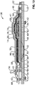
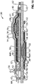
- FIG. 12 is a schematic illustration of another exemplary apparatus 30 for infusing resin 16 into region 32 of part 34 comprising a fibre-reinforced structure by resin infusion.
- Apparatus 30 of FIG. 12 comprises elements previously illustrated and described above therefore such description will not be repeated.
- infusion region 32 may be integral to part 34.
- infusion region 32 may comprise an area of dry fibres which was not completely impregnated by resin during manufacturing or a damaged area of part 34.
- FIG. 12 also shows that resin retaining/releasing device 14, and hence quantity of resin 16 therein, may be laterally offset from infusion region 32 of part 34.
- distribution mesh 48 may extend laterally to form at least part of a resin path between resin retaining/releasing device 14 and infusion region 32.
- distribution mesh 48 may extend laterally to cover infusion region 32 but also be disposed under resin retaining/releasing device 14 so that resin 16 permeating through second sheet 20 may be directed to infusion region 32 via distribution mesh 48.
- the lateral offset of resin retaining/releasing device 14 from infusion region 32 may be advantageous in providing a desired surface finish over infusion region 32.
- the layup of components directly above infusion region 32 may be relatively flat and/or smooth and therefore the risk of having wrinkles, which could negatively impact surface finish, in the layup may be reduced.
- First vacuum port 44 may be laterally offset from infusion region 32 of part 34 in a lateral direction opposite that of the quantity of resin 16 from infusion region 32.
- resin 16 is shown as being positioned to the right of infusion region 32 and first vacuum port 44 is shown as being positioned the left of infusion region 32.
- the relative positions of first vacuum port 44 and resin retaining/releasing device 14 may also favor the flow of resin 16 from the area of resin retaining/releasing device 14 to infusion region 32.
- the evacuation of first volume 41 via first vacuum port 44 may cause first vacuum barrier 40 to collapse, compress the area of resin retaining/releasing device 14 and promote the permeation of resin 16 through second sheet 20.
- the evacuation of first volume 41 via first vacuum port 44 may also help draw resin 16 from the area of resin retaining/releasing device 14 laterally toward first vacuum port 44 and consequently toward infusion region 32 disposed between the area of resin retaining/releasing device 14 and first vacuum port 44.
- heating blanket(s) 46 may be positioned to apply heat to both infusion region 32 and the area of resin retaining/releasing device 14. Accordingly, heating blanket(s) 46 may cover both infusion region 32 and the area of resin retaining/releasing device 14 and also extend between infusion region 32 and the area of resin retaining/releasing device 14 so that a path along which resin 16 may flow may also be heated.
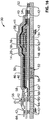
- FIG. 13 is a schematic illustration of another exemplary apparatus 30 for infusing resin into region 32 of part 34 comprising a fibre-reinforced structure by resin infusion.
- Apparatus 30 of FIG. 13 comprises elements previously illustrated and described above therefore such description will not be repeated.
- infusion region 32 may be integral to part 34.
- infusion region 32 may comprise a scarfed region filled with dry fibres or fabric to be infused with resin 16.
- the scarfed region of infusion region 32 may be at least partially filled with dry carbon fabric plies to be infused with resin 16.
- Infusion region 32 may comprise a removed damaged portion (e.g., high porosity level that has been physically removed) of part 34 that has been machined to have a scarfed configuration and filled with dry fibres or fabric and/or other constituent(s) of a composite material prior to resin infusion.
- a film adhesive in infusion region 32 and disposed between the composite material constituent(s) and part 34.
- the use of such film adhesive may adhesively bond the dry fibres or fabric to part 34 and may also result in a structurally stronger repaired infusion region 32 after curing of resin 16.
- the use of the various apparatus 30, 80 and methods 100 disclosed herein may also permit off-gassing the adhesive (i.e., removing air or volatiles) prior to infusing resin 16 into infusion region 32.
- An example of a film adhesive that may be suitable for some applications may be FM® 300-2 adhesive system sold by CYTEC ENGINEERED MATERIALS.
- Infusion region 32 may extend through part 34 and therefore third vacuum barrier 70 may be disposed on opposite side of part 34 and substantially sealed to part 34 via sealing member 42.
- Third vacuum barrier may be of the same type as first vacuum barrier 40 and/or second vacuum barrier 52.
- Third vacuum barrier 70 may substantially prevent or hinder air from entering first volume 41 while first volume 41 is being evacuated via first vacuum port 44. Accordingly, first vacuum barrier 40 and third vacuum barrier 70 may cooperate to define first volume 41.
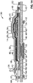
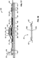
- FIG. 14 is a schematic illustration of another exemplary apparatus 30 for infusing resin into region 32 of part 34 comprising a fibre-reinforced structure by resin infusion.
- Apparatus 30 of FIG. 14 comprises elements previously illustrated and described above therefore such description will not be repeated.
- infusion region 32 may be integral to part 34.
- infusion region 32 may comprise a double-sided scarfed region filled with dry fibres or fabric to be infused with resin 16.
- infusion region 32 may be at least partially filled with dry carbon fabric plies to be infused with resin 16.
- Infusion region 32 may comprise a damaged portion of part 34 that has been removed from part 34 and machined to have a double-sided scarfed configuration prior to resin infusion.
- FIG. 15 is a schematic illustration of another exemplary apparatus 30 for infusing resin 16 into region 32 of part 34 comprising a fibre-reinforced structure by resin infusion.
- Apparatus 30 of FIG. 15 comprises elements previously illustrated and described above therefore such description will not be repeated.
- FIG. 15 shows that in various embodiments disclosed herein a plurality of heating blankets 46A, 46B may be used to provide heat to part 34 and/or resin 16.
- one or more first heating blankets 46A may be disposed on one side of infusion region 32 (and of part 34) and one or more second heating blankets 46B may be disposed on another (e.g., opposite) side of infusion region 32 (and of part 34).
- heating blankets 46A, 46B may be selected based on the particular heating requirements for resin infusion. The number and locations of heating blankets 46A, 46B may also depend on one or more of the type, shape and size of infusion region 32, of part 34 and/or of resin retaining/releasing device 14.
- first heating blanket(s) 46A may be disposed in first volume 41 defined at least in part by first vacuum barrier 40 and third vacuum barrier 70
- second heating blanket 46B may be disposed in second volume 54 defined at least in part by first vacuum barrier 40 and second vacuum barrier 52.
- First heating blanket 46A and second heating blanket 46B may be controlled independently of each other in some embodiments.
- FIG. 16 is a schematic illustration of another exemplary apparatus 30 for infusing resin into region 32.
- Apparatus 30 of FIG. 16 comprises elements previously illustrated and described above therefore such description will not be repeated.
- region 32 may comprise one or more holes at least partially filled with one or more constituents of a composite material to be infused with resin 16 as described above.
- the hole(s) in infusion region 32 may contain dry and relatively short fibres.
- resin infusion into the various types of regions 32 could be achieved whether or not resin retaining/releasing device 14 is laterally offset from infusion region 32.
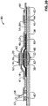
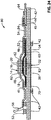
- FIG. 17 is a schematic illustration of an exemplary apparatus 80 for infusing resin 16 into region 32 of part 34 comprising a composite material using resin retaining/releasing device 14 according to another embodiment.
- Apparatus 80 of FIG. 16 comprises elements previously illustrated and described above in relation to apparatus 30 and therefore such description will not be repeated. Like reference numerals have been used to represent like elements.
- first sheet 18 and second sheet 20 may retain (e.g., fully or partially enclose) a quantity of resin 16.
- first sheet 18 and second sheet 20 may not be attached or sealed to each other. Nevertheless, first sheet 18 and opposite second sheet 20 may still at least partially enclose the quantity of resin 16.
- First sheet 18 and second sheet 20 may of the same type(s) and have the same properties as described above.
- First sheet 18 may also serve as first (e.g., inner) vacuum barrier 40 and as first breather 50 described above in relation to apparatus 30 and may be in substantial sealing engagement with part 34 via sealing member(s) 42. Accordingly, first sheet 18 may define at least part of first volume 41. However, as described above, first sheet 18 may not be gas-impermeable as first vacuum barrier 40 of the apparatus 30.
- Apparatus 80 may comprise second (e.g., outer) vacuum barrier 52 which may be configured and function as described above in relation to apparatus 30 and define second volume 54. Since first sheet 18 may be gas permeable, first volume 41 and second volume 54 may permit gas communication between each other through first sheet 18.
- second sheet 20 may be gas-permeable and also resin permeable when the viscosity of resin 16 is below a threshold and optionally when the temperature of resin 16 has reached a threshold temperature. Accordingly, second sheet 20 may form at least part of the resin path between resin 16 and infusion region 32. Second sheet 20 may be attached to heating blanket(s) 46 via blue tape 62. Heating blanket(s) 46 may be disposed inside first volume 41. For example, heating blanket(s) 46 may be disposed between the area of resin retaining/releasing device 14 and infusion region 32. In some embodiments, heating blanket(s) 46 may be disposed between second sheet 20 of resin retaining/releasing device 14 and infusion region 32.
- Heating blanket(s) 46 may be configured to apply heat to resin 16 and also infusion region 32.
- Heating blanket(s) 46 may comprise one or more infusion holes 82 (referred hereinafter as "infusion hole 82") extending therethrough and forming at least part of the infusion path between resin 16 and infusion region 32. Accordingly, when the viscosity of resin 16 is at or below the threshold required to permeate second sheet 20, resin 16 may flow through heating blanket(s) 46 via infusion hole 82 toward infusion region 32.
- Distribution mesh 48 may help resin 16 in spreading across infusion region 32.
- Infusion region 32 may be of any of the types previously explained above.
- Apparatus 80 may also comprise one or more additional breathers 84 that may prevent first sheet 18 from occluding first vacuum port 44 when first volume 41 is evacuated via first vacuum port 44.
- FIG. 18 is an enlarged schematic illustration of second sheet 20 of resin retaining/releasing device 14 of apparatus 80.
- Second sheet 20 may be attached to heater blanket(s) 46 via blue tape 62.
- Second sheet 20 may be disposed such that second layer 20B (e.g., the PTFE membrane) faces resin 16.
- second sheet 20 may be disposed such that first layer 20A faces resin 16.
- First sheet 18 may be disposed such that second layer 18B (e.g., the PTFE membrane) faces resin 16.
- first sheet 18 may be disposed such that first layer 18A faces resin 16.
- FIG. 19 is a schematic illustration of another exemplary apparatus 80 for infusing resin 16 into region 32 of part 34 comprising a fibre-reinforced structure by resin infusion.
- Apparatus 80 of FIG. 19 comprises elements previously illustrated and described above therefore such description will not be repeated.
- infusion region 32 may be integral to part 34.
- infusion region 32 may comprise an area of dry fibres which was not completely impregnated by resin during manufacturing or a removed damaged area of part 34.
- FIG. 19 also shows that the quantity of resin 16 of resin retaining/releasing device 14 may be laterally offset from infusion region 32 of part 34.
- distribution mesh 48 may extend laterally to form at least part of a resin path between resin retaining/releasing device 14 and infusion region 32.
- distribution mesh 48 may extend laterally to cover infusion region 32 but also be disposed under resin retaining/releasing device 14 so that resin 16 permeating through second sheet 20 may be directed to infusion region 32 via distribution mesh 48.
- the lateral offset of resin 16 from infusion region 32 may be advantageous in providing a desired surface finish over infusion region 32 as previously explained above.
- Apparatus 80 may comprise a plurality of heating blankets 46A, 46B for applying heat to different regions.
- heating blanket 46A may be positioned to apply heat to infusion region 32 and heating blanket 46B may be positioned to apply heat to resin 16.
- Infusion hole 82 may be disposed in heating blanket 46B.
- FIG. 20 is a schematic illustration of another exemplary apparatus 80 for infusing resin 16 into infusion region 32 of composite part 34 using resin retaining/releasing device 14.
- Apparatus 80 of FIG. 20 comprises elements previously illustrated and described above therefore such description will not be repeated.
- infusion region 32 may be integral to part 34.
- infusion region 32 may comprise a scarfed region filled with dry fibres or fabric to be infused with resin 16.
- FIG. 21 is a schematic illustration of another exemplary apparatus 80 for infusing resin 16 into infusion region 32 of composite part 34 using resin retaining/releasing device 14.
- Apparatus 80 of FIG. 21 comprises elements previously illustrated and described above therefore such description will not be repeated.
- infusion region 32 may comprise a scarfed region filled with dry fibres or fabric to be infused with resin 16.
- FIG. 21 also shows that the quantity of resin 16 of resin retaining/releasing device 14 may be laterally offset from infusion region 32 of part 34 as previously explained above.
- Apparatus 80 may comprise a plurality of heating blankets 46A, 46B for applying heat to different regions.
- heating blanket 46A may be positioned to apply heat to infusion region 32 and heating blanket 46B may be positioned to apply heat to resin 16.
- Infusion hole 82 may be disposed in heating blanket 46B.
- FIG. 22 is a schematic illustration of another exemplary apparatus 80 for infusing resin 16 into infusion region 32 of composite part 34 using resin retaining/releasing device 14.
- Apparatus 80 of FIG. 22 comprises elements previously illustrated and described above therefore such description will not be repeated.
- infusion region 32 may comprise a double-sided scarfed region filled with dry fibres or fabric to be infused with resin 16.
- infusion region 32 may be at least partially filled with dry carbon fabric plies to be infused with resin 16.
- Infusion region 32 may comprise a damaged portion of part 34 that has been machined to have a double-sided scarfed configuration prior to resin infusion.
- first heating blankets 46A may be disposed on one side of infusion region 32 and one or more second heating blankets 46B may be disposed on another (e.g., opposite) side of infusion region 32.
- the number and locations of heating blankets 46A, 46B may be selected based on the particular heating requirements for resin infusion.
- the number and locations of heating blankets 46A, 46B may also depend on one or more of the type, shape and size of infusion region 32, of part 34 and/or of resin retaining/releasing device 14.
- first heating blanket(s) 46A may be disposed in first volume 41 defined at least in part by first vacuum barrier 40 and third vacuum barrier 70
- second heating blanket 46B may be disposed in first volume 41 between resin retaining/releasing device 14 and infusion region 32.
- FIG. 23 is a schematic illustration of another exemplary apparatus 80 for infusing resin into infusion region 32 of composite part 34 using resin retaining/releasing device 14.
- Apparatus 80 of FIG. 23 comprises elements previously illustrated and described above therefore such description will not be repeated.
- infusion region 32 may comprise a double-sided scarfed region filled with dry fibres or fabric to be infused with resin 16.
- the quantity of resin 16 of resin retaining/releasing device 14 may be laterally offset from infusion region 32 of part 34 as previously explained above.
- Apparatus 80 may comprise a plurality of heating blankets 46A, 46B, 46C for applying heat to different regions.
- heating blanket 46A may be positioned to apply heat to infusion region 32 and heating blanket 46B may be positioned to apply heat to resin 16.
- Heating blanket 46C may be disposed on an opposite side of infusion region 32 than that of heating blanket 46A and may be configured to apply heat to infusion region 32.
- Infusion hole 82 may be disposed in heating blanket 46B.
- a suitable release film 86 may be disposed between infusion region 32 and heating blanket 46C. Release film 86 may comprise a suitable release agent as described above that is substantially resin-impermeable.
- FIG. 24 is a schematic illustration of another exemplary apparatus 80 for infusing resin into infusion region 32 of composite part 34 using resin retaining/releasing device 14.
- Apparatus 80 of FIG. 24 comprises elements previously illustrated and described above therefore such description will not be repeated.
- region 32 may comprise one or more holes at least partially filled with one or more constituents of a composite material such as dry and relatively short fibres as described above.
- FIG. 25 is a schematic illustration of another exemplary apparatus for infusing resin into infusion region 32 of composite part 34 using resin retaining/releasing device 14.
- Apparatus 80 of FIG. 25 comprises elements previously illustrated and described above therefore such description will not be repeated.
- infusion region 32 may comprise one or more holes at least partially filled with one or more constituents of a composite material such as dry and relatively short fibres to be infused with resin 16.
- the quantity of resin 16 of resin retaining/releasing device 14 may be laterally offset from infusion region 32 of part 34 as previously explained above.
- Apparatus 80 may comprise a plurality of heating blankets 46A, 46B for applying heat to different regions.
- heating blanket 46A may be positioned to apply heat to infusion region 32 and heating blanket 46B may be positioned to apply heat to resin 16.
- Infusion hole 82 may be disposed in heating blanket 46B.
- resin infusion into the various types of regions 32 could be achieved whether or not resin retaining/releasing device 14 is laterally offset from infusion region 32.
- regions 32 e.g., dry fibres, scarfed region, double-sided scarfed region and hole filled with short fibres or other composite material constituent
- resin retaining/releasing device 14 could be achieved whether or not resin retaining/releasing device 14 is laterally offset from infusion region 32.
- One or more aspects of one embodiment of apparatus 30, 80 could be combined with one or more aspects of another embodiment of apparatus 30, 80.
- infusion region 32 Depending on the size of infusion region 32 and also whether infusion region extends through part 34, some support may be required on the opposite side of part 34 in addition to third vacuum barrier 70 as shown in FIGS. 13-16 , 24 and 25 for example.
- a relatively rigid support e.g., plate
- suitable release agent may be disposed between third vacuum barrier 70 and infusion region 32 to provide support for the material in infusion region 32 and also prevent the third vacuum barrier 70 from being drawn in infusion region 32 when a vacuum is applied via vacuum port 44.
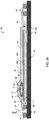
- FIG. 26 is a schematic illustration of another exemplary apparatus 80 for infusing resin 16 into infusion region 32 of composite part 34 where apparatus 80 comprises a single vacuum port 56.
- apparatus 80 comprises a single vacuum port 56.
- first sheet 18 is gas-permeable, it may be sufficient in some applications to omit one of vacuum ports 44, 56 so that only one of vacuum ports 44, 56 is used.
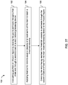
- FIG. 27 is a flowchart of an exemplary method 100 for manufacturing or repairing fibre-reinforced composite materials.
- Method 100 or part thereof may be performed using resin retaining/releasing device 14.
- Method 100 of part thereof may be performed using apparatus 30, 80 described above.
- method 100 may be used for manufacturing or repairing fibre-reinforced composite materials using resin retaining/releasing device 14 where resin retaining/releasing device 14 comprises first sheet 18 and opposite second sheet 20 at least partially enclosing a quantity of resin 16 having a viscosity that is temperature dependent.
- Method 100 may comprise: evacuating gas from a substantially sealed first volume 41 enclosing infusion region 32 by causing gas to permeate through first sheet 18 and through second sheet 20 of resin retaining/releasing device 14 (see block 102); applying heat (e.g., using heater blanket 46) to resin 16 inside resin retaining/releasing device 14 to cause a viscosity of at least some of resin 16 to reach a threshold viscosity (see block 104); and infusing resin 16 into infusion region 32 of part 34 by directing the resin 16 having reached the threshold viscosity to permeate through second sheet 20 and flow from resin retaining/releasing device 14 to infusion region 32.
- heat e.g., using heater blanket 46
- the evacuation of the gas may be performed during any portion or during the entirety of method 100.
- the magnitude of the vacuum inside of first volume 41 may be a residual pressure of about 3 millibars in relation to the atmosphere.
- the permeation of gas through first sheet 18 may occur substantially across the surface of first sheet 18 including the portion of first sheet 18 that may be in contact with resin 16. Accordingly, the use of first sheet 18 may permit the evacuation of gas from resin 16 directly through first sheet 18.
- the evacuation of gas may be performed prior to and/or during the infusion of resin 16 into infusion region 32. In some embodiments, the evacuation of gas may be performed after the infusion of resin into the infusion region.
- the quantity of resin 16 of resin retaining/releasing device 14 may be laterally offset from infusion region 32 of part 34 and method 100 may comprise directing resin 16 toward infusion region 32.
- the quantity of resin 16 of resin retaining/releasing device 14 may be disposed alongside infusion region 32 so that the resin path between resin 16 and infusion region 32 may be relatively short.
- the directing of resin 16 toward infusion region 32 may be achieved by way of distribution mesh 38.
- the flow of resin 16 from the area of resin retaining/releasing device 14 may be at least partially driven by the difference in pressure between the atmosphere ( ⁇ 1 bar) and the residual pressure of about 3 milibars inside of first volume 41 and also by gravity when resin retaining/releasing device 14 is disposed above infusion region 32.
- the flow of resin 16 may also be at least partially driven by the application of a force on resin 16. Such application of force may promote resin 16 having reached the threshold viscosity to permeate through second sheet 20 and to flow toward infusion region 32.
- method 100 may comprise evacuating gas from second volume 54 defined by barrier 52 substantially sealed to part 34 and enclosing first volume 41.
- Method 100 may also comprise applying heat to infusion region 32 of part 34 (e.g., heating blankets 46A, 46B in FIGS. 15 and 23 ).
- the heat may be applies from a first side of part 34 and from an opposite second side of the part 34.
- method 100 may comprise directing resin 16 having reached the threshold viscosity to permeate through hole 82 in heater blanket 46B and flow from the resin retaining/releasing device 14 to infusion region 32.
- Method 100 may comprise using resin 16 as described herein and which may comprise a one-part liquid epoxy.
- threshold viscosity at which resin 16 may begin to permeate second sheet 20 may be about 50 centipoise.
- Method 100 may be used for infusing resin 16 into infusion regions 32 of various types.
- infusion region 32 may comprise one or more of dry fabric, a scarfed region, a hole with dry fibres therein, dry fabric plies and a double-sided scarfed region.
- resin retaining/releasing device 14 in the apparatus 30, 80 and methods 100 disclosed herein may reduce the risk of obtaining porosity due to trapped gas (e.g., air) in fibre-reinforced composite materials manufactured or repaired according to the present disclosure.
- trapped gas e.g., air
Landscapes
- Engineering & Computer Science (AREA)
- Mechanical Engineering (AREA)
- Chemical & Material Sciences (AREA)
- Composite Materials (AREA)
- Casting Or Compression Moulding Of Plastics Or The Like (AREA)
- Moulding By Coating Moulds (AREA)
Claims (15)
- Einrichtung zum Herstellen oder Reparieren von faserverstärkten Verbundmaterialien, wobei die Einrichtung umfasst:
eine Vakuumbarriere (40), die konfiguriert ist, um einen Infusionsbereich (32) zu bedecken, der einen Bestandteil eines Verbundmaterials umfasst, und ein im Wesentlichen abgedichtetes Volumen (41) zu definieren, der den Infusionsbereich (32) umfasst;eine Vakuumöffnung (44) zur Fluidverbindung mit dem Volumen (41); eine Vorrichtung (14) zum Zurückhalten und Steuern der Freisetzung von Harz (16), wobei die Vorrichtung (14) innerhalb des Volumens (41) angeordnet ist und umfasst:eine Menge an Harz (16) mit einer Viskosität, die temperaturabhängig ist; undeine erste Folie (18) und eine gegenüberliegende zweite Folie (20), die die Menge an Harz (16) zumindest teilweise umschließen, wobei die erste Folie (18) und die zweite Folie (20) gasdurchlässig sind, wobei die zweite Folie (20) im Wesentlichen harzundurchlässig ist, wenn die Viskosität des Harzes (16) über einer Schwellenviskosität liegt, und harzdurchlässig ist, wenn die Viskosität des Harzes (16) unter der Schwellenviskosität liegt, wobei die zweite Folie (20) der Harz-Rückhalte-/Freisetzvorrichtung (14) zumindest einen Teil eines Infusionswegs zwischen dem Harz (16) und dem Infusionsbereich (32) bildet, wobei mindestens eine von der ersten Folie (18) und der zweiten Folie (20) eine erste Schicht (18A, 20A), die ein Gewebe umfasst, und eine zweite Schicht (18B, 20B) umfasst, die eine poröse Membran umfasst; undeine Heizeinrichtung (46), die konfiguriert ist, um dem Harz (16) Wärme zuzuführen. - Einrichtung nach Anspruch 1, wobei die Menge an Harz (16) seitlich von dem Infusionsbereich (32) versetzt ist.
- Einrichtung nach Anspruch 2, wobei die Vakuumöffnung (44) seitlich von dem Infusionsbereich (32) in einer seitlichen Richtung entgegengesetzt zu der der Menge an Harz (16) von dem Infusionsbereich (32) versetzt ist.
- Einrichtung nach Anspruch 1, wobei die Menge an Harz (16) neben dem Infusionsbereich (32) angeordnet ist.
- Einrichtung nach einem der Ansprüche 1 bis 4, umfassend ein Harzverteilungsgitter (48), das einen Teil des Infusionswegs zwischen dem Harz (16) und dem Infusionsbereich (32) bildet.
- Einrichtung nach Anspruch 5, umfassend ein Freisetzmittel (38), das zwischen der Harz-Rückhalte-/Freisetzvorrichtung (14) und dem Verteilungsgitter (48) angeordnet ist.
- Einrichtung nach einem der Ansprüche 1 bis 5, umfassend ein Freisetzmittel (38), das zwischen der Harz-Rückhalte-/Freisetzvorrichtung (14) und dem Infusionsbereich (32) angeordnet ist.
- Einrichtung nach einem der Ansprüche 1 bis 7, wobei die Heizeinrichtung (46) eine Heizdecke umfasst, die zumindest einen Teil der Harz-Rückhalte-/Freisetzvorrichtung (14) und zumindest einen Teil des Infusionsbereichs (32) bedeckt.
- Einrichtung nach einem der Ansprüche 1 bis 7, wobei die Heizeinrichtung (46) eine Heizdecke umfasst, die zwischen der Harz-Rückhalte-/Freisetzvorrichtung (14) und dem Infusionsbereich (32) angeordnet ist.
- Einrichtung nach Anspruch 9, wobei die Heizdecke ein Infusionsloch durch diese hindurch umfasst, das zumindest einen Teil des Infusionswegs bildet.
- Einrichtung nach Anspruch 1, wobei die erste Folie (18) im Wesentlichen harzundurchlässig ist, wenn die Viskosität des Harzes unter der Schwellenviskosität liegt.
- Einrichtung nach einem der Ansprüche 1 bis 11, wobei die erste Folie (18) eine Vielzahl von Poren umfasst, die so bemessen sind, dass sie den Durchgang von Gas durch die erste Folie (18) ermöglichen und den Durchgang von Harz (16) durch die erste Folie (18) verhindern, wenn die Viskosität des Harzes (16) unter der Schwellenviskosität liegt.
- Einrichtung nach einem der Ansprüche 1 bis 12, wobei die zweite Folie (20) eine Vielzahl von Poren umfasst, die so bemessen sind, dass sie den Durchgang von Gas durch die zweite Folie (20) ermöglichen und den Durchgang von Harz (16) durch die zweite Folie (20) ermöglichen, wenn die Viskosität des Harzes (16) unter der Schwellenviskosität liegt.
- Einrichtung nach einem der Ansprüche 1 bis 13, wobei die poröse Membran eine poröse Polytetrafluorethylen- (PTFE-) Membran ist.
- Einrichtung nach einem der Ansprüche 1 bis 14, wobei die Schwellenviskosität etwa 50 mPa s beträgt.
Applications Claiming Priority (2)
| Application Number | Priority Date | Filing Date | Title |
|---|---|---|---|
| GB1418921.1A GB2531600A (en) | 2014-10-24 | 2014-10-24 | Apparatus and methods for manufacturing and repairing fibre-reinforced composite materials |
| PCT/GB2015/053164 WO2016063065A1 (en) | 2014-10-24 | 2015-10-22 | Apparatus and methods for manufacturing and repairing fibre-reinforced composite materials |
Publications (2)
| Publication Number | Publication Date |
|---|---|
| EP3209489A1 EP3209489A1 (de) | 2017-08-30 |
| EP3209489B1 true EP3209489B1 (de) | 2021-11-17 |
Family
ID=52103325
Family Applications (1)
| Application Number | Title | Priority Date | Filing Date |
|---|---|---|---|
| EP15790192.7A Active EP3209489B1 (de) | 2014-10-24 | 2015-10-22 | Vorrichtung und verfahren zur herstellung und reparatur von faserverstärkten verbundwerkstoffen |
Country Status (6)
| Country | Link |
|---|---|
| US (1) | US10960617B2 (de) |
| EP (1) | EP3209489B1 (de) |
| CN (1) | CN107073848B (de) |
| CA (2) | CA2964530C (de) |
| GB (1) | GB2531600A (de) |
| WO (1) | WO2016063065A1 (de) |
Families Citing this family (10)
| Publication number | Priority date | Publication date | Assignee | Title |
|---|---|---|---|---|
| US20170057183A1 (en) * | 2014-05-05 | 2017-03-02 | Woodwelding Ag | Completing a fiber composite part |
| ES2911260T3 (es) * | 2016-10-07 | 2022-05-18 | Airbus Operations Sl | Sistema y método de curado de piezas de material compuesto de matriz polimérica en procesos de fabricación y de reparación |
| US10899090B2 (en) * | 2017-06-26 | 2021-01-26 | Faserverbund Innovations UG (haftungsbeschränkt) | Method for producing fiber composite components by means of a vacuum injection method |
| GB2568958A (en) * | 2017-12-04 | 2019-06-05 | Short Brothers Plc | Resin barrier device |
| US11040496B2 (en) * | 2017-12-19 | 2021-06-22 | The Boeing Company | Methods and systems for repairing composite structures |
| RU2694352C1 (ru) * | 2018-01-10 | 2019-07-11 | Публичное Акционерное Общество "Воронежское акционерное самолетостроительное общество" | Способ ремонта изделий из полимерных композиционных материалов |
| FR3093298B1 (fr) * | 2019-03-01 | 2021-03-12 | Safran | Réparation ou reprise de fabrication d’une pièce en matériau composite |
| EP4392239A1 (de) * | 2021-08-23 | 2024-07-03 | Faserverbund Innovations UG (haftungsbeschränkt) | Preform-patch und verfahren zur nachträglichen verstärkung eines faserverbundbauteils |
| WO2024163421A1 (en) * | 2023-01-31 | 2024-08-08 | Rtx Corporation | Polyimide composite repair apparatus and method via high temperature resin transfer molding |
| EP4610035A1 (de) * | 2024-02-27 | 2025-09-03 | Siemens Gamesa Renewable Energy A/S | Verfahren und spannvorrichtung zur herstellung und/oder reparatur einer windturbinenschaufel |
Family Cites Families (14)
| Publication number | Priority date | Publication date | Assignee | Title |
|---|---|---|---|---|
| FR2763882B1 (fr) * | 1997-05-29 | 1999-08-20 | Aerospatiale | Outillage de reparation sur site d'une structure composite presentant une zone endommagee et procede correspondant |
| DE10013409C1 (de) * | 2000-03-17 | 2000-11-23 | Daimler Chrysler Ag | Verfahren und Vorrichtung zur Herstellung von faserverstärkten Bauteilen mittels eines Injektionsverfahrens |
| US6818159B2 (en) * | 2000-03-17 | 2004-11-16 | Deutsches Zentrum Fuer Luft-Und Raumfahrt E.V. | Process for the production of a composite consisting of a fiber reinforced material |
| US7138028B2 (en) | 2001-07-26 | 2006-11-21 | The Boeing Company | Vacuum assisted resin transfer method for co-bonding composite laminate structures |
| US6428497B1 (en) | 2001-09-01 | 2002-08-06 | Richard A. Crouch | Therapeutic table system |
| CA2739517C (en) * | 2008-11-18 | 2013-08-27 | Mitsubishi Heavy Industries, Ltd. | Composite material manufacturing device and composite material manufacturing method |
| US8652371B2 (en) * | 2008-11-20 | 2014-02-18 | Cytec Technology Corp. | Constant pressure infusion process for resin transfer molding |
| US7939011B2 (en) | 2009-08-14 | 2011-05-10 | The Boeing Company | Resin containment and injection system and method |
| US8444127B2 (en) * | 2009-12-14 | 2013-05-21 | The Boeing Company | High temperature composite patch tool |
| US9682514B2 (en) * | 2010-06-25 | 2017-06-20 | The Boeing Company | Method of manufacturing resin infused composite parts using a perforated caul sheet |
| WO2012149939A2 (en) * | 2011-05-04 | 2012-11-08 | Vestas Wind Systems A/S | Method of preparing a composite laminate |
| US8945321B2 (en) | 2011-05-30 | 2015-02-03 | The Boeing Company | Method and apparatus for reworking structures using resin infusion of fiber preforms |
| US8968617B2 (en) * | 2012-11-12 | 2015-03-03 | Spirit Aerosystems, Inc. | Thermo-rheological fluid valve for resin infusion |
| US9579873B2 (en) * | 2013-02-07 | 2017-02-28 | The Boeing Company | Method and apparatus for reworking structures |
-
2014
- 2014-10-24 GB GB1418921.1A patent/GB2531600A/en not_active Withdrawn
-
2015
- 2015-10-22 EP EP15790192.7A patent/EP3209489B1/de active Active
- 2015-10-22 WO PCT/GB2015/053164 patent/WO2016063065A1/en not_active Ceased
- 2015-10-22 CN CN201580057016.9A patent/CN107073848B/zh not_active Expired - Fee Related
- 2015-10-22 CA CA2964530A patent/CA2964530C/en active Active
- 2015-10-22 CA CA3181578A patent/CA3181578A1/en active Pending
- 2015-10-22 US US15/521,000 patent/US10960617B2/en active Active
Also Published As
| Publication number | Publication date |
|---|---|
| CA2964530A1 (en) | 2016-04-28 |
| CA3181578A1 (en) | 2016-04-28 |
| US10960617B2 (en) | 2021-03-30 |
| US20170341320A1 (en) | 2017-11-30 |
| EP3209489A1 (de) | 2017-08-30 |
| GB201418921D0 (en) | 2014-12-10 |
| CA2964530C (en) | 2023-08-22 |
| GB2531600A (en) | 2016-04-27 |
| CN107073848B (zh) | 2020-07-03 |
| CN107073848A (zh) | 2017-08-18 |
| WO2016063065A1 (en) | 2016-04-28 |
Similar Documents
| Publication | Publication Date | Title |
|---|---|---|
| EP3209489B1 (de) | Vorrichtung und verfahren zur herstellung und reparatur von faserverstärkten verbundwerkstoffen | |
| JP3653249B2 (ja) | 射出成形法による繊維強化構造部品の製造方法および装置 | |
| CN101365580B (zh) | 整体树脂浸渍系统装置和方法 | |
| JP5877156B2 (ja) | ロータブレードの製造方法及びその製造装置 | |
| CN101151142B (zh) | 蜂窝复合结构体及其形成方法 | |
| US20080210372A1 (en) | Composite article debulking process | |
| JP6541976B2 (ja) | 複合部品を真空バギングするシステム及び方法 | |
| US20040219244A1 (en) | Method and device for producing fiber-reinforced components by an injection method | |
| DK2647492T3 (en) | Resinstrømelement to a vacuum assisted resinoverførselsstøbeproces | |
| US8388885B2 (en) | Membrane structure for vacuum assisted molding fiber reinforced article | |
| JP2010502483A (ja) | ハニカムサンドイッチパネルを製造する方法 | |
| US20220118721A1 (en) | Apparatus and methods for repairing composite laminates | |
| JP2010512257A (ja) | 複合構造体の形成及び硬化のためのシステム及び方法 | |
| BRPI1100272A2 (pt) | método de fabricação de um artigo compósito | |
| US8066503B2 (en) | Controlled delta pressure bulk resin infusion system | |
| US10052826B2 (en) | Bulk resin infusion | |
| KR20130056239A (ko) | 섬유-보강 플라스틱으로부터 복합 성형 부분을 제조하기 위한 방법 및 장치 | |
| EP3266595B1 (de) | Verfahren und system zur harzinfusion einer verbundstoffvorform | |
| CA2900635A1 (en) | Multifunctional mandrel end cap and method |
Legal Events
| Date | Code | Title | Description |
|---|---|---|---|
| STAA | Information on the status of an ep patent application or granted ep patent |
Free format text: STATUS: THE INTERNATIONAL PUBLICATION HAS BEEN MADE |
|
| PUAI | Public reference made under article 153(3) epc to a published international application that has entered the european phase |
Free format text: ORIGINAL CODE: 0009012 |
|
| STAA | Information on the status of an ep patent application or granted ep patent |
Free format text: STATUS: REQUEST FOR EXAMINATION WAS MADE |
|
| 17P | Request for examination filed |
Effective date: 20170412 |
|
| AK | Designated contracting states |
Kind code of ref document: A1 Designated state(s): AL AT BE BG CH CY CZ DE DK EE ES FI FR GB GR HR HU IE IS IT LI LT LU LV MC MK MT NL NO PL PT RO RS SE SI SK SM TR |
|
| AX | Request for extension of the european patent |
Extension state: BA ME |
|
| DAV | Request for validation of the european patent (deleted) | ||
| DAX | Request for extension of the european patent (deleted) | ||
| GRAP | Despatch of communication of intention to grant a patent |
Free format text: ORIGINAL CODE: EPIDOSNIGR1 |
|
| STAA | Information on the status of an ep patent application or granted ep patent |
Free format text: STATUS: GRANT OF PATENT IS INTENDED |
|
| INTG | Intention to grant announced |
Effective date: 20210531 |
|
| RAP3 | Party data changed (applicant data changed or rights of an application transferred) |
Owner name: SHORT BROTHERS PLC |
|
| GRAS | Grant fee paid |
Free format text: ORIGINAL CODE: EPIDOSNIGR3 |
|
| GRAA | (expected) grant |
Free format text: ORIGINAL CODE: 0009210 |
|
| STAA | Information on the status of an ep patent application or granted ep patent |
Free format text: STATUS: THE PATENT HAS BEEN GRANTED |
|
| AK | Designated contracting states |
Kind code of ref document: B1 Designated state(s): AL AT BE BG CH CY CZ DE DK EE ES FI FR GB GR HR HU IE IS IT LI LT LU LV MC MK MT NL NO PL PT RO RS SE SI SK SM TR |
|
| REG | Reference to a national code |
Ref country code: GB Ref legal event code: FG4D |
|
| REG | Reference to a national code |
Ref country code: DE Ref legal event code: R096 Ref document number: 602015075104 Country of ref document: DE |
|
| REG | Reference to a national code |
Ref country code: IE Ref legal event code: FG4D |
|
| REG | Reference to a national code |
Ref country code: AT Ref legal event code: REF Ref document number: 1447706 Country of ref document: AT Kind code of ref document: T Effective date: 20211215 |
|
| REG | Reference to a national code |
Ref country code: LT Ref legal event code: MG9D |
|
| REG | Reference to a national code |
Ref country code: NL Ref legal event code: MP Effective date: 20211117 |
|
| REG | Reference to a national code |
Ref country code: AT Ref legal event code: MK05 Ref document number: 1447706 Country of ref document: AT Kind code of ref document: T Effective date: 20211117 |
|
| PG25 | Lapsed in a contracting state [announced via postgrant information from national office to epo] |
Ref country code: RS Free format text: LAPSE BECAUSE OF FAILURE TO SUBMIT A TRANSLATION OF THE DESCRIPTION OR TO PAY THE FEE WITHIN THE PRESCRIBED TIME-LIMIT Effective date: 20211117 Ref country code: LT Free format text: LAPSE BECAUSE OF FAILURE TO SUBMIT A TRANSLATION OF THE DESCRIPTION OR TO PAY THE FEE WITHIN THE PRESCRIBED TIME-LIMIT Effective date: 20211117 Ref country code: FI Free format text: LAPSE BECAUSE OF FAILURE TO SUBMIT A TRANSLATION OF THE DESCRIPTION OR TO PAY THE FEE WITHIN THE PRESCRIBED TIME-LIMIT Effective date: 20211117 Ref country code: BG Free format text: LAPSE BECAUSE OF FAILURE TO SUBMIT A TRANSLATION OF THE DESCRIPTION OR TO PAY THE FEE WITHIN THE PRESCRIBED TIME-LIMIT Effective date: 20220217 Ref country code: AT Free format text: LAPSE BECAUSE OF FAILURE TO SUBMIT A TRANSLATION OF THE DESCRIPTION OR TO PAY THE FEE WITHIN THE PRESCRIBED TIME-LIMIT Effective date: 20211117 |
|
| PG25 | Lapsed in a contracting state [announced via postgrant information from national office to epo] |
Ref country code: IS Free format text: LAPSE BECAUSE OF FAILURE TO SUBMIT A TRANSLATION OF THE DESCRIPTION OR TO PAY THE FEE WITHIN THE PRESCRIBED TIME-LIMIT Effective date: 20220317 Ref country code: SE Free format text: LAPSE BECAUSE OF FAILURE TO SUBMIT A TRANSLATION OF THE DESCRIPTION OR TO PAY THE FEE WITHIN THE PRESCRIBED TIME-LIMIT Effective date: 20211117 Ref country code: PT Free format text: LAPSE BECAUSE OF FAILURE TO SUBMIT A TRANSLATION OF THE DESCRIPTION OR TO PAY THE FEE WITHIN THE PRESCRIBED TIME-LIMIT Effective date: 20220317 Ref country code: PL Free format text: LAPSE BECAUSE OF FAILURE TO SUBMIT A TRANSLATION OF THE DESCRIPTION OR TO PAY THE FEE WITHIN THE PRESCRIBED TIME-LIMIT Effective date: 20211117 Ref country code: NO Free format text: LAPSE BECAUSE OF FAILURE TO SUBMIT A TRANSLATION OF THE DESCRIPTION OR TO PAY THE FEE WITHIN THE PRESCRIBED TIME-LIMIT Effective date: 20220217 Ref country code: NL Free format text: LAPSE BECAUSE OF FAILURE TO SUBMIT A TRANSLATION OF THE DESCRIPTION OR TO PAY THE FEE WITHIN THE PRESCRIBED TIME-LIMIT Effective date: 20211117 Ref country code: LV Free format text: LAPSE BECAUSE OF FAILURE TO SUBMIT A TRANSLATION OF THE DESCRIPTION OR TO PAY THE FEE WITHIN THE PRESCRIBED TIME-LIMIT Effective date: 20211117 Ref country code: HR Free format text: LAPSE BECAUSE OF FAILURE TO SUBMIT A TRANSLATION OF THE DESCRIPTION OR TO PAY THE FEE WITHIN THE PRESCRIBED TIME-LIMIT Effective date: 20211117 Ref country code: GR Free format text: LAPSE BECAUSE OF FAILURE TO SUBMIT A TRANSLATION OF THE DESCRIPTION OR TO PAY THE FEE WITHIN THE PRESCRIBED TIME-LIMIT Effective date: 20220218 Ref country code: ES Free format text: LAPSE BECAUSE OF FAILURE TO SUBMIT A TRANSLATION OF THE DESCRIPTION OR TO PAY THE FEE WITHIN THE PRESCRIBED TIME-LIMIT Effective date: 20211117 |
|
| PG25 | Lapsed in a contracting state [announced via postgrant information from national office to epo] |
Ref country code: SM Free format text: LAPSE BECAUSE OF FAILURE TO SUBMIT A TRANSLATION OF THE DESCRIPTION OR TO PAY THE FEE WITHIN THE PRESCRIBED TIME-LIMIT Effective date: 20211117 Ref country code: SK Free format text: LAPSE BECAUSE OF FAILURE TO SUBMIT A TRANSLATION OF THE DESCRIPTION OR TO PAY THE FEE WITHIN THE PRESCRIBED TIME-LIMIT Effective date: 20211117 Ref country code: RO Free format text: LAPSE BECAUSE OF FAILURE TO SUBMIT A TRANSLATION OF THE DESCRIPTION OR TO PAY THE FEE WITHIN THE PRESCRIBED TIME-LIMIT Effective date: 20211117 Ref country code: EE Free format text: LAPSE BECAUSE OF FAILURE TO SUBMIT A TRANSLATION OF THE DESCRIPTION OR TO PAY THE FEE WITHIN THE PRESCRIBED TIME-LIMIT Effective date: 20211117 Ref country code: DK Free format text: LAPSE BECAUSE OF FAILURE TO SUBMIT A TRANSLATION OF THE DESCRIPTION OR TO PAY THE FEE WITHIN THE PRESCRIBED TIME-LIMIT Effective date: 20211117 Ref country code: CZ Free format text: LAPSE BECAUSE OF FAILURE TO SUBMIT A TRANSLATION OF THE DESCRIPTION OR TO PAY THE FEE WITHIN THE PRESCRIBED TIME-LIMIT Effective date: 20211117 |
|
| REG | Reference to a national code |
Ref country code: DE Ref legal event code: R097 Ref document number: 602015075104 Country of ref document: DE |
|
| PLBE | No opposition filed within time limit |
Free format text: ORIGINAL CODE: 0009261 |
|
| STAA | Information on the status of an ep patent application or granted ep patent |
Free format text: STATUS: NO OPPOSITION FILED WITHIN TIME LIMIT |
|
| 26N | No opposition filed |
Effective date: 20220818 |
|
| PG25 | Lapsed in a contracting state [announced via postgrant information from national office to epo] |
Ref country code: AL Free format text: LAPSE BECAUSE OF FAILURE TO SUBMIT A TRANSLATION OF THE DESCRIPTION OR TO PAY THE FEE WITHIN THE PRESCRIBED TIME-LIMIT Effective date: 20211117 |
|
| PG25 | Lapsed in a contracting state [announced via postgrant information from national office to epo] |
Ref country code: SI Free format text: LAPSE BECAUSE OF FAILURE TO SUBMIT A TRANSLATION OF THE DESCRIPTION OR TO PAY THE FEE WITHIN THE PRESCRIBED TIME-LIMIT Effective date: 20211117 |
|
| PGFP | Annual fee paid to national office [announced via postgrant information from national office to epo] |
Ref country code: DE Payment date: 20220929 Year of fee payment: 8 |
|
| PG25 | Lapsed in a contracting state [announced via postgrant information from national office to epo] |
Ref country code: MC Free format text: LAPSE BECAUSE OF FAILURE TO SUBMIT A TRANSLATION OF THE DESCRIPTION OR TO PAY THE FEE WITHIN THE PRESCRIBED TIME-LIMIT Effective date: 20211117 Ref country code: IT Free format text: LAPSE BECAUSE OF FAILURE TO SUBMIT A TRANSLATION OF THE DESCRIPTION OR TO PAY THE FEE WITHIN THE PRESCRIBED TIME-LIMIT Effective date: 20211117 |
|
| REG | Reference to a national code |
Ref country code: CH Ref legal event code: PL |
|
| REG | Reference to a national code |
Ref country code: BE Ref legal event code: MM Effective date: 20221031 |
|
| PG25 | Lapsed in a contracting state [announced via postgrant information from national office to epo] |
Ref country code: LU Free format text: LAPSE BECAUSE OF NON-PAYMENT OF DUE FEES Effective date: 20221022 |
|
| PG25 | Lapsed in a contracting state [announced via postgrant information from national office to epo] |
Ref country code: LI Free format text: LAPSE BECAUSE OF NON-PAYMENT OF DUE FEES Effective date: 20221031 Ref country code: CH Free format text: LAPSE BECAUSE OF NON-PAYMENT OF DUE FEES Effective date: 20221031 |
|
| PG25 | Lapsed in a contracting state [announced via postgrant information from national office to epo] |
Ref country code: BE Free format text: LAPSE BECAUSE OF NON-PAYMENT OF DUE FEES Effective date: 20221031 |
|
| PG25 | Lapsed in a contracting state [announced via postgrant information from national office to epo] |
Ref country code: IE Free format text: LAPSE BECAUSE OF NON-PAYMENT OF DUE FEES Effective date: 20221022 |
|
| PG25 | Lapsed in a contracting state [announced via postgrant information from national office to epo] |
Ref country code: HU Free format text: LAPSE BECAUSE OF FAILURE TO SUBMIT A TRANSLATION OF THE DESCRIPTION OR TO PAY THE FEE WITHIN THE PRESCRIBED TIME-LIMIT; INVALID AB INITIO Effective date: 20151022 |
|
| PG25 | Lapsed in a contracting state [announced via postgrant information from national office to epo] |
Ref country code: CY Free format text: LAPSE BECAUSE OF FAILURE TO SUBMIT A TRANSLATION OF THE DESCRIPTION OR TO PAY THE FEE WITHIN THE PRESCRIBED TIME-LIMIT Effective date: 20211117 |
|
| REG | Reference to a national code |
Ref country code: DE Ref legal event code: R119 Ref document number: 602015075104 Country of ref document: DE |
|
| PG25 | Lapsed in a contracting state [announced via postgrant information from national office to epo] |
Ref country code: MK Free format text: LAPSE BECAUSE OF FAILURE TO SUBMIT A TRANSLATION OF THE DESCRIPTION OR TO PAY THE FEE WITHIN THE PRESCRIBED TIME-LIMIT Effective date: 20211117 |
|
| PG25 | Lapsed in a contracting state [announced via postgrant information from national office to epo] |
Ref country code: DE Free format text: LAPSE BECAUSE OF NON-PAYMENT OF DUE FEES Effective date: 20240501 |
|
| PG25 | Lapsed in a contracting state [announced via postgrant information from national office to epo] |
Ref country code: MT Free format text: LAPSE BECAUSE OF FAILURE TO SUBMIT A TRANSLATION OF THE DESCRIPTION OR TO PAY THE FEE WITHIN THE PRESCRIBED TIME-LIMIT Effective date: 20211117 |
|
| PGFP | Annual fee paid to national office [announced via postgrant information from national office to epo] |
Ref country code: GB Payment date: 20240926 Year of fee payment: 10 |
|
| PGFP | Annual fee paid to national office [announced via postgrant information from national office to epo] |
Ref country code: FR Payment date: 20241009 Year of fee payment: 10 |
|
| PG25 | Lapsed in a contracting state [announced via postgrant information from national office to epo] |
Ref country code: TR Free format text: LAPSE BECAUSE OF FAILURE TO SUBMIT A TRANSLATION OF THE DESCRIPTION OR TO PAY THE FEE WITHIN THE PRESCRIBED TIME-LIMIT Effective date: 20211117 |