EP3209367B1 - Medizinische koronarsinuselektrode - Google Patents
Medizinische koronarsinuselektrode Download PDFInfo
- Publication number
- EP3209367B1 EP3209367B1 EP15851769.8A EP15851769A EP3209367B1 EP 3209367 B1 EP3209367 B1 EP 3209367B1 EP 15851769 A EP15851769 A EP 15851769A EP 3209367 B1 EP3209367 B1 EP 3209367B1
- Authority
- EP
- European Patent Office
- Prior art keywords
- lead
- electrode
- distal end
- electrodes
- shaped
- Prior art date
- Legal status (The legal status is an assumption and is not a legal conclusion. Google has not performed a legal analysis and makes no representation as to the accuracy of the status listed.)
- Active
Links
Images


Classifications
-
- A—HUMAN NECESSITIES
- A61—MEDICAL OR VETERINARY SCIENCE; HYGIENE
- A61N—ELECTROTHERAPY; MAGNETOTHERAPY; RADIATION THERAPY; ULTRASOUND THERAPY
- A61N1/00—Electrotherapy; Circuits therefor
- A61N1/02—Details
- A61N1/04—Electrodes
- A61N1/05—Electrodes for implantation or insertion into the body, e.g. heart electrode
- A61N1/056—Transvascular endocardial electrode systems
-
- A—HUMAN NECESSITIES
- A61—MEDICAL OR VETERINARY SCIENCE; HYGIENE
- A61N—ELECTROTHERAPY; MAGNETOTHERAPY; RADIATION THERAPY; ULTRASOUND THERAPY
- A61N1/00—Electrotherapy; Circuits therefor
- A61N1/18—Applying electric currents by contact electrodes
- A61N1/32—Applying electric currents by contact electrodes alternating or intermittent currents
- A61N1/36—Applying electric currents by contact electrodes alternating or intermittent currents for stimulation
- A61N1/362—Heart stimulators
- A61N1/365—Heart stimulators controlled by a physiological parameter, e.g. heart potential
- A61N1/368—Heart stimulators controlled by a physiological parameter, e.g. heart potential comprising more than one electrode co-operating with different heart regions
- A61N1/3686—Heart stimulators controlled by a physiological parameter, e.g. heart potential comprising more than one electrode co-operating with different heart regions configured for selecting the electrode configuration on a lead
-
- A—HUMAN NECESSITIES
- A61—MEDICAL OR VETERINARY SCIENCE; HYGIENE
- A61N—ELECTROTHERAPY; MAGNETOTHERAPY; RADIATION THERAPY; ULTRASOUND THERAPY
- A61N1/00—Electrotherapy; Circuits therefor
- A61N1/18—Applying electric currents by contact electrodes
- A61N1/32—Applying electric currents by contact electrodes alternating or intermittent currents
- A61N1/36—Applying electric currents by contact electrodes alternating or intermittent currents for stimulation
- A61N1/362—Heart stimulators
- A61N1/3627—Heart stimulators for treating a mechanical deficiency of the heart, e.g. congestive heart failure or cardiomyopathy
-
- A—HUMAN NECESSITIES
- A61—MEDICAL OR VETERINARY SCIENCE; HYGIENE
- A61N—ELECTROTHERAPY; MAGNETOTHERAPY; RADIATION THERAPY; ULTRASOUND THERAPY
- A61N1/00—Electrotherapy; Circuits therefor
- A61N1/02—Details
- A61N1/04—Electrodes
- A61N1/05—Electrodes for implantation or insertion into the body, e.g. heart electrode
- A61N1/056—Transvascular endocardial electrode systems
- A61N2001/0585—Coronary sinus electrodes
Definitions
- the present disclosure pertains to medical electrical leads, and, more particularly, to implantable medical electrical leads that reduce undesired neural stimulation.
- Implantable medical devices for example cardiac pacemakers and defibrillators, often include elongate medical electrical leads having one or more electrodes to sense electrical activity and deliver therapeutic stimulation.
- leads With the advent of left ventricular pacing to alleviate heart failure, leads have been advanced into the coronary veins in order to position the electrodes of the leads at left ventricular pacing sites, typically located in proximity to the base of the left ventricle.
- left ventricular pacing leads along with methods for implanting such leads, have been developed, there is still a need for a lead including features that facilitate delivery to, and fixation at, sites in the coronary vasculature.
- Exemplary active fixation leads include US Patent No. 7,860,580, issued to Sommer, et al. , US Patent No. 7,532,939, issued to Sommer, et al . and US Patent Application No. 13/793,622, filed March 11, 2013 by Sommer, et al. .
- Shaped leads can also be adapted for placement in the coronary vasculature.
- Exemplary shaped leads or catheters include US Patent No. 7,313,444, issued to Pianca et al. , US Patent No. 5,387,233, issued to Alferness, et al. , US Patent No.
- the self-anchoring lead disclosed in Pianchi et al. includes radially spaced electrodes that are electrically active around their circumference, which can result in unwanted phrenic nerve stimulation. It is desirable to develop a coronary sinus lead that does not inadvertently cause phrenic nerve stimulation.
- Document US-A-2003/195603 discloses an intravenous lead.
- the present disclosure may comprise an improvement to the prior art leads as disclosed above.
- the disclosure is directed to an intravenous medical electrical lead that includes an elongated lead body.
- the elongated lead body comprises a length between a proximal end and a shaped distal end.
- the lead body defines a longitudinal axis extending between the proximal end and the shaped distal end.
- the lead body includes a set of electrodes radially spaced apart. Each electrode includes an electrically active portion and an insulated portion at an outer circumference of the electrode.
- the lead body is further configured to move through a coronary vein while substantially retaining its shaped or curved distal end.
- the lead body may freely move longitudinally within a delivery catheter that guides the lead to myocardial tissue.
- the lead body rotates within the tubular body of the delivery catheter, the lead body is configured to rotate back into a position such that the electrically active portion of a set of electrodes faces myocardial tissue when exiting the guide catheter while the insulated portion of the lead faces neural tissue such as the phrenic nerve.
- the medical electrical lead disclosed herein is able to achieve lower pacing thresholds to capture (i.e. evoke a response) cardiac tissue, which means less energy must be expended by the implantable medical device. Additionally, the lead results in higher pacing impedance due to use of electrodes with a decreased surface area. A higher pacing impedance decreases the current drain on the implantable medical device. Decreased current drain and energy consumption may increase the life of the implantable medical device.
- FIGs. 1-2 is a plan view of an exemplary intravenous medical electrical lead 10 connected through to a guide catheter 34 such as the ATTAIN CATHETER ® developed and sold by Medtronic, Inc. of Minneapolis, Minnesota.
- Lead 10 is configured to deliver electrical stimulation to tissue (e.g. ventricular cardiac pacing) and/or sense signals from the tissue.
- Lead 10 includes proximal end and a distal end 120 with a lead body 150 therebetween that generally defines a longitudinal axis. At the proximal end is located an in-line bipolar connector assembly 30.
- Distal end 120 which includes set of electrodes 104a-d (e.g. ring electrodes, directional electrodes, electrodes shown in FIG.
- lead 10 can be configured in many different ways to ensure lead 10 stays in position to deliver electrical therapy to cardiac tissue.
- lead 10 can be fixed in a location based upon a self-anchoring shape, other passive fixation means (e.g. adhesive etc.) and/or active fixation means (e.g. tines, screw, helix etc.).
- the self-anchoring shaped lead is configured to wrap or hug the curved-shaped heart.
- first, second, and third angles comprise 106°, 102° and 77° angles, respectively. Additionally, each radius for each of the first, second and third angles is measured from the center point of each arch. For example, r1, associated with ⁇ 1, is about 10-16 mm (0.400 inches), r2, associated with ⁇ 2, is about 10-16 mm (0.400 inches), and r3, associated with ⁇ 1, is about 10-16 mm (0.400 inches). The length of shaped lead 10 that is directly proximal to r1 is about 12.7 mm (0.500 inches).
- first angle ⁇ 1 The length of the liner that extends over first angle ⁇ 1 is about (I 1 ) 15.01 mm (0.591 inches), second angle ⁇ 2 is about (I 2 ) 16.66 mm (0.656 inches), and third angle ⁇ 3 is about (I 3 ) 18.16 mm (0.715 inches).
- Each curved area is formed and maintained by creating a polymeric liner or jacket that has a durometer of about 30D to about 50D.
- Exemplary liners that can be used in conjunction with the present disclosure are shown and described with respect to U.S. Pat. No. 8,005,549 issued August 23, 2011 , U.S. Pat. No. 7,783,365 issued August 24, 2010 , and assigned to the assignee of the present invention.
- ATTAIN PERFORMA TM Model 4298 quadripolar lead is another exemplary insulative material that can be used.
- the curved or shaped polymeric liner exhibits the same or about the same stiffness as the generally linear areas of the remaining portion of the liner for the lead body 150.
- the curve(s) in the lead can be thermoformed using known techniques.
- Shaped lead 10 can be thermoset in an oven at 148,°C (300°F) for less than 30 minutes.
- the curved distal end 120B can include two curves having angles ⁇ 1 and ⁇ 2 .
- ⁇ 1 can range from about 60 to about 80 degrees.
- ⁇ 2 can range from about 65 to about 85 degrees.
- a lead distal end 120C can employ a single sweep curve having an angle ⁇ of about 90 degrees to about 180 degrees from the center line (i.e. center of the lead body) or longitudinal axis 36 of the lead body 150.
- the distal end 120 is substantially J-shaped. J-shaped lead 400 includes an electrically active portion of electrodes on one longitudinal side of the lead 400 and an insulated portion (or lacks electrodes) on the other diametrically opposed longitudinal side of the lead 400, which is placed in proximity of neural tissue.
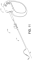
- Lead body 150 has a proximal portion, to which a connector module 312 is coupled thereto as shown in FIGs. 11-12 .
- Examples of connector modules may be seen with respect to U.S. Pat. No. 7,601,033 issued October 13, 2009 , U.S. Pat. No. 7,654,843 issued February 2, 2010 , and assigned to the assignee of the present invention.
- Connector module 312, as illustrated, takes the form of an IS-4 bipolar connecter, but any appropriate connector mechanism may be substituted.
- Connector module 312 electrically couples a proximal end of a lead 10 to various internal electrical components of implantable medical device 210.
- Lead body 150 is formed by an insulative sheath or liner of a biocompatible polymer surrounding internal metallic conductors.
- a non-conductive portion 110 is positioned over or coupled to the outer surface of each ring electrode 104a-d in order to prevent electrical stimuli emanating from a portion of each electrode.
- insulated portion 110 extends along the outer circumference and the longitudinal length of the electrode 104.
- insulated portion 110 can extend about the length and width of the electrode along one side of the lead. Insulated portion 110 partially surrounds electrode 104a-d in the range of about 120 degrees to about 360 degrees.
- Exemplary thickness of polymer e.g.
- the curved or shaped lead 10 is movable between a compact configuration while within the tubular body of the guide catheter and expands into an expanded configuration after the curved distal portion of the lead 10 exits the tubular body of the guide catheter.
- lead 10 can be attached to cardiac tissue using a side helix, as shown and described in US Patent No. US8755909 B2 to Sommer et al.
- a helical tip may be used at the distal end of lead 10.
- pacing toward the myocardium becomes more efficient.
- Increased efficiency of pacing allows each electrode decrease or have a smaller surface area electrode for higher impedance.
- a large surface area current electrode can be 5.8 mm 2 surface electrodes while the present disclosure employs a 2.3 mm 2 to 2.9 mm 2 , which is slightly less or equal than half the surface area of conventional electrodes.
- the smaller surface area of the electrode raises the impedance which reduces the amount of current drain.
- the smaller electrode surface area located on lead 10, directed 104a-d towards the myocardium, is believed to assist in achieving good thresholds (i.e. voltage required to capture the heart) and higher impedance.
- FIG. 13 is a functional block diagram of one exemplary configuration of the IMD 216.
- the IMD 216 may include a control module 81, a therapy delivery module 84 (e.g., which may include a stimulation generator), a sensing module 86, and a power source 90.
- therapy delivery module 84 may deliver pacing stimulus (e.g., pacing pulses) via ring electrodes 40, 44, 45, 46, 47, 48 coupled to leads 218, 10, and 222, respectively, and/or helical tip electrodes 42 and 50 of leads 218 and 222. Further, for example, therapy delivery module 84 may deliver defibrillation shocks to heart 15 via at least two of electrodes 58, 62, 64, 66. In some examples, therapy delivery module 84 may be configured to deliver pacing, cardioversion, or defibrillation stimulation in the form of electrical pulses. In other examples, therapy delivery module 84 may be configured deliver one or more of these types of stimulation in the form of other signals, such as sine waves, square waves, and/or other substantially continuous time signals.
- pacing stimulus e.g., pacing pulses
- therapy delivery module 84 may deliver defibrillation shocks to heart 15 via at least two of electrodes 58, 62, 64, 66.
- the IMD 216 may further include a switch module 85 and the control module 81 (e.g., the processor 80) may use the switch module 85 to select, e.g., via a data/address bus, which of the available electrodes are used to deliver therapy such as pacing pulses for pacing therapy, or which of the available electrodes are used for sensing.
- the switch module 85 may include a switch array, switch matrix, multiplexer, or any other type of switching device suitable to selectively couple the sensing module 86 and/or the therapy delivery module 84 to one or more selected electrodes. More specifically, the therapy delivery module 84 may include a plurality of pacing output circuits.
- Each pacing output circuit of the plurality of pacing output circuits may be selectively coupled, e.g., using the switch module 85, to one or more of the electrodes 40, 42, 44, 45, 46, 47, 48, 50, 58, 62, 64, 66 (e.g., a pair of electrodes for delivery of therapy to a pacing vector).
- each electrode can be selectively coupled to one of the pacing output circuits of the therapy delivery module using the switching module 85.
- the sensing module 86 is coupled (e.g., electrically coupled) to sensing apparatus, which may include, among additional sensing apparatus, the electrodes 40, 42, 44, 45, 46, 47, 48, 50, 58, 62, 64, 66 to monitor electrical activity of the heart 12, e.g., electrocardiogram (ECG)/electrogram (EGM) signals, etc.
- ECG electrocardiogram
- EMG electrocardiogram
- EMG electrocardiogram
- ECM electrocardiogram
- the ECG/EGM signals may be used to measure or monitor activation times (e.g., ventricular activations times, etc.), heart rate (HR), heart rate variability (HRV), heart rate turbulence (HRT), deceleration/acceleration capacity, deceleration sequence incidence, T-wave alternans (TWA), P-wave to P-wave intervals (also referred to as the P-P intervals or A-A intervals), R-wave to R-wave intervals (also referred to as the R-R intervals or V-V intervals), P-wave to QRS complex intervals (also referred to as the P-R intervals, A-V intervals, or P-Q intervals), QRS-complex morphology, ST segment (i.e., the segment that connects the QRS complex and the T-wave), T-wave changes, QT intervals, electrical vectors, etc.
- activation times e.g., ventricular activations times, etc.
- HR heart rate
- HRV heart rate variability
- HRT
- the switch module 85 may be also be used with the sensing module 86 to select which of the available electrodes are used, or enabled, to, e.g., sense electrical activity of the patient's heart (e.g., one or more electrical vectors of the patient's heart using any combination of the electrodes 40, 42, 44, 45, 46, 47, 48, 50, 58, 62, 64, 66).
- the switch module 85 may be also be used with the sensing module 86 to select which of the available electrodes are not to be used (e.g., disabled) to, e.g., sense electrical activity of the patient's heart (e.g., one or more electrical vectors of the patient's heart using any combination of the electrodes 40, 42, 44, 45, 46, 47, 48, 50, 58, 62, 64, 66), etc.
- the control module 81 may select the electrodes that function as sensing electrodes via the switch module within the sensing module 86, e.g., by providing signals via a data/address bus.
- sensing module 86 includes a channel that includes an amplifier with a relatively wider pass band than the R-wave or P-wave amplifiers. Signals from the selected sensing electrodes may be provided to a multiplexer, and thereafter converted to multi-bit digital signals by an analog-to-digital converter for storage in memory 82, e.g., as an electrogram (EGM). In some examples, the storage of such EGMs in memory 82 may be under the control of a direct memory access circuit.
- EGM electrogram
- control module 81 may operate as an interrupt driven device, and may be responsive to interrupts from pacer timing and control module, where the interrupts may correspond to the occurrences of sensed P-waves and R-waves and the generation of cardiac pacing pulses. Any necessary mathematical calculations may be performed by the processor 80 and any updating of the values or intervals controlled by the pacer timing and control module may take place following such interrupts.
- a portion of memory 82 may be configured as a plurality of recirculating buffers, capable of holding one or more series of measured intervals, which may be analyzed by, e.g., the processor 80 in response to the occurrence of a pace or sense interrupt to determine whether the patient's heart 12 is presently exhibiting atrial or ventricular tachyarrhythmia.
- the telemetry module 88 of the control module 81 may include any suitable hardware, firmware, software, or any combination thereof for communicating with another device, such as a programmer.
- the telemetry module 88 may receive downlink telemetry from and send uplink telemetry to a programmer with the aid of an antenna, which may be internal and/or external.
- the processor 80 may provide the data to be uplinked to a programmer and the control signals for the telemetry circuit within the telemetry module 88, e.g., via an address/data bus.
- the telemetry module 88 may provide received data to the processor 80 via a multiplexer.
- the various components of the IMD 216 are further coupled to a power source 90, which may include a rechargeable or non-rechargeable battery.
- a power source 90 may include a rechargeable or non-rechargeable battery.
- a non-rechargeable battery may be selected to last for several years, while a rechargeable battery may be inductively charged from an external device, e.g., on a daily or weekly basis.
- FIG. 14 is another embodiment of a functional block diagram for IMD 216.
- FIG. 14 depicts bipolar RA lead 222, bipolar RV lead 218, and bipolar LV CS lead 10 without the LA CS pace/sense electrodes and coupled with an implantable pulse generator (IPG) circuit 31 having programmable modes and parameters of a bi-ventricular DDD/R type known in the pacing art.
- the sensor signal processing circuit 91 indirectly couples to the timing circuit 83 and via data and control bus to microcomputer circuitry 33.
- the IPG circuit 31 is illustrated in a functional block diagram divided generally into a microcomputer circuit 33 and a pacing circuit 21.
- the pacing circuit 21 includes the digital controller/timer circuit 83, the output amplifiers circuit 51, the sense amplifiers circuit 55, the RF telemetry transceiver 41, the activity sensor circuit 35 as well as a number of other circuits and components described below.
- Crystal oscillator circuit 89 provides the basic timing clock for the pacing circuit 21, while battery 29 provides power.
- Power-on-reset circuit 87 responds to initial connection of the circuit to the battery for defining an initial operating condition and similarly, resets the operative state of the device in response to detection of a low battery condition.
- Reference mode circuit 37 generates stable voltage reference and currents for the analog circuits within the pacing circuit 21, while analog to digital converter ADC and multiplexer circuit 39 digitizes analog signals and voltage to provide real time telemetry if a cardiac signals from sense amplifiers 55, for uplink transmission via RF transmitter and receiver circuit 41.
- Voltage reference and bias circuit 37, ADC and multiplexer 39, power-on-reset circuit 87 and crystal oscillator circuit 89 may correspond to any of those presently used in current marketed implantable cardiac pacemakers.
- the signals output by one or more physiologic sensor are employed as a rate control parameter (RCP) to derive a physiologic escape interval.
- RCP rate control parameter
- the escape interval is adjusted proportionally to the patient's activity level developed in the patient activity sensor (PAS) circuit 35 in the depicted, exemplary IPG circuit 31.
- the patient activity sensor 27 is coupled to the IPG housing and may take the form of a piezoelectric crystal transducer as is well known in the art and its output signal is processed and used as the RCP.
- Sensor 27 generates electrical signals in response to sensed physical activity that are processed by activity circuit 35 and provided to digital controller/timer circuit 83.
- Activity circuit 35 and associated sensor 27 may correspond to the circuitry disclosed in U.S. Pat.
- Uplink telemetry capabilities will typically include the ability to transmit stored digital information, e.g. operating modes and parameters, EGM histograms, and other events, as well as real time EGMs of atrial and/or ventricular electrical activity and marker channel pulses indicating the occurrence of sensed and paced depolarizations in the atrium and ventricle, as are well known in the pacing art.
- Microcomputer 33 contains a microprocessor 80 and associated system clock and on-processor RAM and ROM chips 82A and 82B, respectively.
- microcomputer circuit 33 includes a separate RAM/ROM chip 82C to provide additional memory capacity.
- Microprocessor 80 normally operates in a reduced power consumption mode and is interrupt driven. Microprocessor 80 is awakened in response to defined interrupt events, which may include A-TRIG, RV-TRIG, LV-TRIG signals generated by timers in digital timer/controller circuit 83 and A-EVENT, RV-EVENT, and LV-EVENT signals generated by sense amplifiers circuit 55, among others.
- microprocessor 80 is a custom microprocessor adapted to fetch and execute instructions stored in RAM/ROM unit 82 in a conventional manner. It is contemplated, however, that other implementations may be suitable to practice the present invention. For example, an off-the-shelf, commercially available microprocessor or microcontroller, or custom application-specific, hardwired logic, or state-machine type circuit may perform the functions of microprocessor 80.
- Digital controller/timer circuit 83 operates under the general control of the microcomputer 33 to control timing and other functions within the pacing circuit 320 and includes a set of timing and associated logic circuits of which certain ones pertinent to the present invention are depicted.
- the depicted timing circuits include URI/LRI timers 83A, V-V delay timer 83B, intrinsic interval timers 83C for timing elapsed V-EVENT to V-EVENT intervals or V-EVENT to A-EVENT intervals or the V-V conduction interval, escape interval timers 83D for timing A-A, V-A, and/or V-V pacing escape intervals, an AV delay interval timer 83E for timing the A-LVp delay (or A-RVp delay) from a preceding A-EVENT or A-TRIG, a post-ventricular timer 83F for timing post-ventricular time periods, and a date/time clock 83G.
- the AV delay interval timer 83E is loaded with an appropriate delay interval for one ventricular chamber (e.g., either an A-RVp delay or an A-LVp delay as determined using known methods) to time-out starting from a preceding A-PACE or A-EVENT.
- the interval timer 83E triggers pacing stimulus delivery, and can be based on one or more prior cardiac cycles (or from a data set empirically derived for a given patient).
- the post-event timer 83F time out the post-ventricular time period following an RV-EVENT or LV-EVENT or a RV-TRIG or LV-TRIG and post-atrial time periods following an A-EVENT or A-TRIG.
- the durations of the post-event time periods may also be selected as programmable parameters stored in the microcomputer 33.
- the post-ventricular time periods include the PVARP, a post-atrial ventricular blanking period (PAVBP), a ventricular blanking period (VBP), a post-ventricular atrial blanking period (PVARP) and a ventricular refractory period (VRP) although other periods can be suitably defined depending, at least in part, on the operative circuitry employed in the pacing engine.
- the post-atrial time periods include an atrial refractory period (ARP) during which an A-EVENT is ignored for the purpose of resetting any AV delay, and an atrial blanking period (ABP) during which atrial sensing is disabled.
- ARP atrial refractory period
- ABSP atrial blanking period
- the output amplifiers circuit 51 contains a RA pace pulse generator (and a LA pace pulse generator if LA pacing is provided), a RV pace pulse generator, and a LV pace pulse generator or corresponding to any of those presently employed in commercially marketed cardiac pacemakers providing atrial and ventricular pacing.
- digital controller/timer circuit 83 In order to trigger generation of an RV-PACE or LV-PACE pulse, digital controller/timer circuit 83 generates the RV-TRIG signal at the time-out of the A-RVp delay (in the case of RV pre-excitation) or the LV-TRIG at the time-out of the A-LVp delay (in the case of LV pre-excitation) provided by AV delay interval timer 83E (or the V-V delay timer 83B).
- digital controller/timer circuit 83 generates an RA-TRIG signal that triggers output of an RA-PACE pulse (or an LA-TRIG signal that triggers output of an LA-PACE pulse, if provided) at the end of the V-A escape interval timed by escape interval timers 83D.
- the output amplifiers circuit 51 includes switching circuits for coupling selected pace electrode pairs from among the lead conductors and the IND_CAN electrode 20 to the RA pace pulse generator (and LA pace pulse generator if provided), RV pace pulse generator and LV pace pulse generator.
- Pace/sense electrode pair selection and control circuit 53 selects lead conductors and associated pace electrode pairs to be coupled with the atrial and ventricular output amplifiers within output amplifiers circuit 51 for accomplishing RA, LA, RV and LV pacing.
- the sense amplifiers circuit 55 contains sense amplifiers corresponding to any of those presently employed in contemporary cardiac pacemakers for atrial and ventricular pacing and sensing.
- High impedance P-wave and R-wave sense amplifiers may be used to amplify a voltage difference signal that is generated across the sense electrode pairs by the passage of cardiac depolarization wavefronts.
- the high impedance sense amplifiers use high gain to amplify the low amplitude signals and rely on pass band filters, time domain filtering and amplitude threshold comparison to discriminate a P-wave or R-wave from background electrical noise.
- Digital controller/timer circuit 83 controls sensitivity settings of the atrial and ventricular sense amplifiers 55.
- dimension D3 which is about 1.067 mm (0.042 inches).
- dimension L7 can be about 1.778 mm (070 inches).
- L7 can be 2.286 mm (0.090 inches).
- dimension 176 was stated as a summation of L3+L4+L5 which equaled 2.794 mm (0.110 inches) but can also be 3.302 mm (0.130 inches).
Landscapes
- Health & Medical Sciences (AREA)
- Heart & Thoracic Surgery (AREA)
- Cardiology (AREA)
- Life Sciences & Earth Sciences (AREA)
- Engineering & Computer Science (AREA)
- Biomedical Technology (AREA)
- Nuclear Medicine, Radiotherapy & Molecular Imaging (AREA)
- Radiology & Medical Imaging (AREA)
- Animal Behavior & Ethology (AREA)
- General Health & Medical Sciences (AREA)
- Public Health (AREA)
- Veterinary Medicine (AREA)
- Vascular Medicine (AREA)
- Biophysics (AREA)
- Physiology (AREA)
- Hospice & Palliative Care (AREA)
- Electrotherapy Devices (AREA)
Claims (15)
- Intravenöse Lead, umfassend:ein Lumen, das sich von einem proximalen Ende zu einem distalen Ende erstreckt, wobei eine Lead-Abgabevorrichtung in dem Lumen angeordnet werden kann; undeinen länglichen Lead-Körper (150), der eine Länge zwischen einem proximalen Ende und einem geformten distalen Ende (120) umfasst, wobei der Lead-Körper eine Längsachse definiert, die zwischen dem proximalen Ende und dem geformten distalen Ende verläuft, wobei der Lead-Körper einen Außenumfang aufweist und mit einem Satz von Elektroden (104a-d) bereitgestellt ist, die in Umfangsrichtung beabstandet sind, wobei jede Elektrode an einem Außenumfang einen elektrisch aktiven Abschnitt und einen isolierten Abschnitt aufweist, wobei der Lead-Körper (150) ferner konfiguriert ist, um sich durch einen röhrenförmigen Körper eines Führungskatheters zu bewegen, während er eine erste Form aufweist, die sein geformtes, nicht lineares distales Ende im Wesentlichen beibehält, während die Lead innerhalb des röhrenförmigen Körpers angeordnet ist, und wobei sich das geformte distale Ende beim Verlassen des röhrenförmigen Körpers des Führungskatheters in eine zweite Form oder ursprüngliche Form ausdehnt, sodass der elektrisch aktive Abschnitt jeder Elektrode dem Myokardgewebe zugewandt ist, während der isolierte Abschnitt jeder Elektrode einem Zwerchfellnerv eines Patienten zugewandt ist, dadurch gekennzeichnet, dass wenn die Lead (10) so gedreht wird, dass die isolierten Abschnitte dem Herzmuskelgewebe zugewandt sind, die mechanische Struktur und die Steifheit des geformten distalen Endes (120) der Lead in Verbindung mit der gekrümmten Herzform konfiguriert sind, um eine Rotationskraft auszuüben, um die Lead wieder in die Konfiguration zurück zu drehen, in der die elektrisch aktiven Abschnitte der Lead (10) dem Herzmuskelgewebe zugewandt sind.
- Lead nach Anspruch 1, wobei der elektrisch aktive Abschnitt am Außenumfang jeder Elektrode entlang derselben Ebene der Längsachse ausgerichtet ist und der isolierte Abschnitt am Außenumfang jeder Elektrode entlang einer anderen Ebene der Längsachse ausgerichtet ist.
- Lead nach einem der Ansprüche 1 bis 2, wobei das distale Ende der Lead wellenförmig ist.
- Lead nach einem der Ansprüche 1 bis 3, wobei das zweite oder ursprünglich geformte distale Ende der Lead in der expandierten Konfiguration eine erste, zweite und dritte Krümmung von 106°, 102° bzw. 77° einschließt,
wobei sich die erste, zweite und dritte Kurve über eine erste, zweite und dritte Länge von 15,01 mm (0,591 Zoll), 16,65 mm (0,656 Zoll) bzw. 18,161 mm (0,715 Zoll) erstrecken. - Lead nach einem der Ansprüche 2 bis 4, wobei das geformte distale Ende etwa 7,5 cm (3 Zoll) von einer distalen Spitze der Lead weg vorsteht.
- Lead nach einem der Ansprüche 1 bis 5, wobei ein elektrisch aktiver Abschnitt der Elektrode weniger als die Hälfte einer Elektrode beträgt.
- Lead nach einem der Ansprüche 5 bis 6, wobei die Elektrode von einem Außenumfang eines Lead-Körpers weg vorsteht.
- Lead nach einem der Ansprüche 1 bis 7, wobei jede Elektrode einen konvexen Abschnitt einschließt, der von einem Außenumfang weg und zum Lead-Körper hin vorsteht.
- Lead nach einem der Ansprüche 1 bis 8, wobei sich der konvexe Abschnitt über einen Basisabschnitt der Elektrode erstreckt.
- Lead nach einem der Ansprüche 1 bis 9, wobei jede Elektrode konfiguriert ist, um elektrische Stimulationen in einem Bereich von 180° oder weniger im Vergleich zu 360°, die bei herkömmlichen Elektroden verwendet werden, abzugeben.
- Lead nach einem der Ansprüche 1 bis 10, wobei der isolierte Abschnitt jede Elektrode in einem Bereich von 120 Grad bis 360 Grad teilweise umgibt.
- Lead nach einem der Ansprüche 1 bis 11, wobei der aktive Abschnitt jeder Elektrode eine Ausdehnung der elektrischen Stimuli in einem Bereich von 100 Grad bis 140 Grad zulässt.
- Lead nach einem der Ansprüche 1 bis 12, wobei der aktive Teil jeder Elektrode eine elektrische Stimulusausbreitung von bis zu maximal 220 Grad um die Elektrode herum ermöglicht.
- Lead nach einem der Ansprüche 1 bis 13, wobei der aktive Teil jeder Elektrode eine elektrische Stimulusausbreitung von bis zu maximal 140 Grad um die Elektrode herum zulässt.
- Medizinische Einrichtung zum Abgeben einer intravenösen Lead, umfassend:einen Führungskatheter zum Abgeben eines distalen Endes der Lead durch ein Gefäß während der Implantation der Lead, wobei der Führungskatheter einen röhrenförmigen Körper mit einem distalen Abschnitt und einem proximalen Abschnitt zur Aufnahme der Lead umfasst;die Lead-Abgabevorrichtung, die konfiguriert ist, um im Lumen der Lead angeordnet zu werden; unddie intravenöse Lead nach einem der Ansprüche 1 bis 14.
Applications Claiming Priority (5)
| Application Number | Priority Date | Filing Date | Title |
|---|---|---|---|
| US14/523,058 US10016591B2 (en) | 2014-10-24 | 2014-10-24 | Medical electrical lead |
| US14/523,240 US10532206B2 (en) | 2014-10-24 | 2014-10-24 | Coronary sinus medical electrical lead |
| US14/523,137 US9901732B2 (en) | 2014-10-24 | 2014-10-24 | Medical electrical lead |
| US14/523,257 US20160114155A1 (en) | 2014-10-24 | 2014-10-24 | Coronary sinus medical electrical lead |
| PCT/US2015/057251 WO2016065345A1 (en) | 2014-10-24 | 2015-10-23 | Coronary sinus medical electrical lead |
Publications (3)
| Publication Number | Publication Date |
|---|---|
| EP3209367A1 EP3209367A1 (de) | 2017-08-30 |
| EP3209367A4 EP3209367A4 (de) | 2018-08-01 |
| EP3209367B1 true EP3209367B1 (de) | 2025-07-09 |
Family
ID=54365463
Family Applications (2)
| Application Number | Title | Priority Date | Filing Date |
|---|---|---|---|
| EP15787863.8A Active EP3209368B1 (de) | 2014-10-24 | 2015-10-23 | Medizinische elektrische leitung |
| EP15851769.8A Active EP3209367B1 (de) | 2014-10-24 | 2015-10-23 | Medizinische koronarsinuselektrode |
Family Applications Before (1)
| Application Number | Title | Priority Date | Filing Date |
|---|---|---|---|
| EP15787863.8A Active EP3209368B1 (de) | 2014-10-24 | 2015-10-23 | Medizinische elektrische leitung |
Country Status (3)
| Country | Link |
|---|---|
| EP (2) | EP3209368B1 (de) |
| CN (2) | CN107073255B (de) |
| WO (4) | WO2016065345A1 (de) |
Families Citing this family (16)
| Publication number | Priority date | Publication date | Assignee | Title |
|---|---|---|---|---|
| US20180214686A1 (en) * | 2017-01-31 | 2018-08-02 | Cardiac Pacemakers, Inc. | Implantable medical device |
| US11338135B2 (en) | 2017-10-23 | 2022-05-24 | Cardiac Pacemakers, Inc. | Medical devices for cancer therapy with electric field shaping elements |
| US12403306B2 (en) * | 2017-10-23 | 2025-09-02 | Cardiac Pacemakers, Inc. | Electric field shaping leads for treatment of cancer |
| CN111491694A (zh) * | 2017-12-22 | 2020-08-04 | 心脏起搏器股份公司 | 用于血管部署的可植入医疗装置 |
| US11291833B2 (en) * | 2018-05-09 | 2022-04-05 | Medtronic, Inc. | Bonding strip for fixing an electrode coil to a lead body |
| US11266828B2 (en) * | 2018-12-06 | 2022-03-08 | Medtronic, Inc. | Implantable medical lead with moveable conductors |
| EP4397361B1 (de) | 2019-04-22 | 2025-11-05 | Boston Scientific Scimed, Inc. | Vorrichtungen zur verabreichung elektrischer stimulation zur behandlung von krebs |
| US12109412B2 (en) | 2019-04-22 | 2024-10-08 | Boston Scientific Scimed, Inc. | Combination electrical and chemotherapeutic treatment of cancer |
| WO2020219336A1 (en) | 2019-04-22 | 2020-10-29 | Boston Scientific Scimed, Inc. | Electrical stimulation devices for cancer treatment |
| JP7476231B2 (ja) | 2019-04-23 | 2024-04-30 | ボストン サイエンティフィック サイムド,インコーポレイテッド | 温熱療法又は熱モニタと共に行われる電気刺激 |
| WO2020219517A2 (en) | 2019-04-23 | 2020-10-29 | Boston Scientific Scimed, Inc. | Electrical stimulation for cancer treatment with internal and external electrodes |
| CN113747936B (zh) | 2019-04-23 | 2024-06-18 | 波士顿科学国际有限公司 | 用于电刺激来治疗癌症的电极 |
| WO2021173509A1 (en) | 2020-02-24 | 2021-09-02 | Boston Scientific Scimed, Inc. | Systems and methods for treatment of pancreatic cancer |
| US12171484B2 (en) * | 2020-05-27 | 2024-12-24 | Medtronic, Inc. | Safety default return path for electric field therapy |
| CN113713259B (zh) * | 2021-11-02 | 2022-03-18 | 上海神奕医疗科技有限公司 | 植入电极及植入电刺激系统 |
| WO2025191396A1 (en) * | 2024-03-15 | 2025-09-18 | Medtronic, Inc. | Medical device telemetry extender |
Family Cites Families (42)
| Publication number | Priority date | Publication date | Assignee | Title |
|---|---|---|---|---|
| US4428378A (en) | 1981-11-19 | 1984-01-31 | Medtronic, Inc. | Rate adaptive pacer |
| US5052388A (en) | 1989-12-22 | 1991-10-01 | Medtronic, Inc. | Method and apparatus for implementing activity sensing in a pulse generator |
| US5387233A (en) | 1993-01-11 | 1995-02-07 | Incontrol, Inc. | Intravenous cardiac lead with improved fixation and method |
| US5843148A (en) * | 1996-09-27 | 1998-12-01 | Medtronic, Inc. | High resolution brain stimulation lead and method of use |
| US6212434B1 (en) * | 1998-07-22 | 2001-04-03 | Cardiac Pacemakers, Inc. | Single pass lead system |
| US5925073A (en) | 1998-02-23 | 1999-07-20 | Cardiac Pacemakers, Inc. | Intravenous cardiac lead with wave shaped fixation segment |
| US6556862B2 (en) | 1998-03-19 | 2003-04-29 | Cardiac Pacemakers, Inc. | Method and apparatus for treating supraventricular tachyarrhythmias |
| US7313444B2 (en) * | 1998-11-20 | 2007-12-25 | Pacesetter, Inc. | Self-anchoring coronary sinus lead |
| US6321123B1 (en) | 1999-03-08 | 2001-11-20 | Medtronic Inc. | J-shaped coronary sinus lead |
| US6129750A (en) | 1999-03-23 | 2000-10-10 | Cardiac Pacemakers, Inc. | Fixation mechanism for a coronary venous pacing lead |
| US6584362B1 (en) * | 2000-08-30 | 2003-06-24 | Cardiac Pacemakers, Inc. | Leads for pacing and/or sensing the heart from within the coronary veins |
| US6757970B1 (en) * | 2000-11-07 | 2004-07-06 | Advanced Bionics Corporation | Method of making multi-contact electrode array |
| US7027852B2 (en) * | 2002-05-21 | 2006-04-11 | Pacesetter, Inc. | Lead with distal tip surface electrodes connected in parallel |
| US7383091B1 (en) * | 2003-06-05 | 2008-06-03 | Pacesetter, Inc. | Medical electrical lead providing far-field signal attenuation |
| US20090171381A1 (en) * | 2007-12-28 | 2009-07-02 | Schmitz Gregory P | Devices, methods and systems for neural localization |
| US9026228B2 (en) * | 2004-10-21 | 2015-05-05 | Medtronic, Inc. | Transverse tripole neurostimulation lead, system and method |
| US7684863B2 (en) | 2004-12-20 | 2010-03-23 | Medtronic, Inc. | LV threshold measurement and capture management |
| JP5027797B2 (ja) | 2005-03-31 | 2012-09-19 | プロテウス バイオメディカル インコーポレイテッド | 心臓再同期化のための多重電極ペーシングの自動最適化 |
| US7532939B2 (en) | 2005-07-21 | 2009-05-12 | Medtronic, Inc. | Active fixation medical lead |
| US7729782B2 (en) * | 2005-11-15 | 2010-06-01 | Medtronic, Inc. | Delivery catheter |
| US7848802B2 (en) * | 2006-02-24 | 2010-12-07 | Medtronic, Inc. | Programming interface with a concentric axial view of a stimulation lead with complex electrode array geometry |
| US7654843B2 (en) | 2006-02-28 | 2010-02-02 | Medtronic, Inc. | Connector assembly with internal seals and manufacturing method |
| US7860580B2 (en) * | 2006-04-24 | 2010-12-28 | Medtronic, Inc. | Active fixation medical electrical lead |
| US20080114230A1 (en) * | 2006-11-14 | 2008-05-15 | Bruce Addis | Electrode support |
| US7717754B2 (en) | 2006-12-07 | 2010-05-18 | Medtronic, Inc. | Connector assembly with internal seals and manufacturing method |
| US7844345B2 (en) * | 2007-02-08 | 2010-11-30 | Neuropace, Inc. | Drug eluting lead systems |
| US20080228250A1 (en) * | 2007-03-16 | 2008-09-18 | Mironer Y Eugene | Paddle lead comprising opposing diagonal arrangements of electrodes and method for using the same |
| US8233979B1 (en) * | 2007-03-21 | 2012-07-31 | Pacesetter, Inc. | Distributed anode cardiac pacing and sensing |
| EP2195081A1 (de) * | 2007-08-20 | 2010-06-16 | Medtronic, INC. | Elektrodenkonfigurationen für direktionale leitungen |
| EP2195078B1 (de) * | 2007-08-20 | 2013-10-09 | Medtronic, Inc. | Implantierbare medizinische leitung mit vorgespannter elektrode |
| US7894914B2 (en) * | 2007-08-28 | 2011-02-22 | Cardiac Pacemakers, Inc. | Medical device electrodes including nanostructures |
| US20090088827A1 (en) * | 2007-10-02 | 2009-04-02 | Cardiac Pacemakers, Inc | Lead assembly providing sensing or stimulation of spaced-apart myocardial contact areas |
| US9833616B2 (en) * | 2009-01-02 | 2017-12-05 | Medtronic, Inc. | System and method for cardiac lead |
| AU2010236196B2 (en) * | 2009-04-16 | 2015-11-12 | Boston Scientific Neuromodulation Corporation | Deep brain stimulation current steering with split electrodes |
| US8887387B2 (en) * | 2009-07-07 | 2014-11-18 | Boston Scientific Neuromodulation Corporation | Methods of manufacture of leads with a radially segmented electrode array |
| US8463398B2 (en) * | 2009-12-30 | 2013-06-11 | Cardiac Pacemakers, Inc. | Electrode surface modification for imparting current density directionality in lead electrodes |
| CN102686273B (zh) * | 2009-12-30 | 2015-04-22 | 心脏起搏器公司 | 用于医疗电导线的终端连接器装置 |
| US8571665B2 (en) * | 2010-03-23 | 2013-10-29 | Boston Scientific Neuromodulation Corporation | Helical radial spacing of contacts on a cylindrical lead |
| US20120203316A1 (en) * | 2011-02-08 | 2012-08-09 | Boston Scientific Neuromodulation Corporation | Leads with segmented electrodes for electrical stimulation of planar regions and methods of making and using |
| US20130184801A1 (en) * | 2012-01-13 | 2013-07-18 | Pacesetter, Inc. | Lead shaped for stimulation at the base left ventricle |
| WO2014000231A1 (en) * | 2012-06-28 | 2014-01-03 | Shanghai Microport Medical (Group) Co., Ltd. | Active cardiac electrical lead |
| US9204820B2 (en) * | 2012-12-31 | 2015-12-08 | Biosense Webster (Israel) Ltd. | Catheter with combined position and pressure sensing structures |
-
2015
- 2015-10-23 WO PCT/US2015/057251 patent/WO2016065345A1/en not_active Ceased
- 2015-10-23 WO PCT/US2015/057118 patent/WO2016065263A1/en not_active Ceased
- 2015-10-23 WO PCT/US2015/057253 patent/WO2016069415A1/en not_active Ceased
- 2015-10-23 EP EP15787863.8A patent/EP3209368B1/de active Active
- 2015-10-23 CN CN201580057397.0A patent/CN107073255B/zh active Active
- 2015-10-23 EP EP15851769.8A patent/EP3209367B1/de active Active
- 2015-10-23 WO PCT/US2015/057123 patent/WO2016065266A1/en not_active Ceased
- 2015-10-23 CN CN201580057488.4A patent/CN107073271B/zh active Active
Also Published As
| Publication number | Publication date |
|---|---|
| EP3209367A4 (de) | 2018-08-01 |
| CN107073255B (zh) | 2020-10-02 |
| CN107073271A (zh) | 2017-08-18 |
| EP3209367A1 (de) | 2017-08-30 |
| WO2016065263A1 (en) | 2016-04-28 |
| WO2016065266A1 (en) | 2016-04-28 |
| CN107073255A (zh) | 2017-08-18 |
| WO2016069415A1 (en) | 2016-05-06 |
| EP3209368A1 (de) | 2017-08-30 |
| EP3209368B1 (de) | 2024-01-10 |
| CN107073271B (zh) | 2021-06-22 |
| WO2016065345A1 (en) | 2016-04-28 |
Similar Documents
| Publication | Publication Date | Title |
|---|---|---|
| EP3209367B1 (de) | Medizinische koronarsinuselektrode | |
| US9901732B2 (en) | Medical electrical lead | |
| US10532213B2 (en) | Criteria for determination of local tissue latency near pacing electrode | |
| US9155897B2 (en) | Criteria for optimal electrical resynchronization during biventricular pacing | |
| EP3089783B1 (de) | Detektion von anodischer erfassung | |
| US20220257948A1 (en) | Current steering to achieve spatial selectivity for his bundle pacing | |
| EP3768374B1 (de) | Überwachung der his-bündelstimulationserfassung während einer ventrikulären schrittmachertherapie | |
| WO2014078032A1 (en) | Capture threshold measurement for selection of pacing vector | |
| CN114980967A (zh) | 房室结刺激 | |
| US11801390B2 (en) | Identification and adjustment for loss of effective cardiac resynchronization therapy | |
| US10532206B2 (en) | Coronary sinus medical electrical lead | |
| EP4188523B1 (de) | Stimulation über septumdurchbohrende vene | |
| US10016591B2 (en) | Medical electrical lead | |
| US20160114155A1 (en) | Coronary sinus medical electrical lead | |
| US20070250128A1 (en) | Refractory period stimulation to increase ventricular performance |
Legal Events
| Date | Code | Title | Description |
|---|---|---|---|
| STAA | Information on the status of an ep patent application or granted ep patent |
Free format text: STATUS: THE INTERNATIONAL PUBLICATION HAS BEEN MADE |
|
| PUAI | Public reference made under article 153(3) epc to a published international application that has entered the european phase |
Free format text: ORIGINAL CODE: 0009012 |
|
| STAA | Information on the status of an ep patent application or granted ep patent |
Free format text: STATUS: REQUEST FOR EXAMINATION WAS MADE |
|
| 17P | Request for examination filed |
Effective date: 20170524 |
|
| AK | Designated contracting states |
Kind code of ref document: A1 Designated state(s): AL AT BE BG CH CY CZ DE DK EE ES FI FR GB GR HR HU IE IS IT LI LT LU LV MC MK MT NL NO PL PT RO RS SE SI SK SM TR |
|
| AX | Request for extension of the european patent |
Extension state: BA ME |
|
| RIN1 | Information on inventor provided before grant (corrected) |
Inventor name: CLEMENS, WILLIAM, J. Inventor name: FRANKE, LINDA, L. Inventor name: SOMMER, JOHN, L. |
|
| DAV | Request for validation of the european patent (deleted) | ||
| DAX | Request for extension of the european patent (deleted) | ||
| A4 | Supplementary search report drawn up and despatched |
Effective date: 20180702 |
|
| RIC1 | Information provided on ipc code assigned before grant |
Ipc: A61N 1/00 20060101AFI20180626BHEP |
|
| STAA | Information on the status of an ep patent application or granted ep patent |
Free format text: STATUS: EXAMINATION IS IN PROGRESS |
|
| 17Q | First examination report despatched |
Effective date: 20220203 |
|
| GRAP | Despatch of communication of intention to grant a patent |
Free format text: ORIGINAL CODE: EPIDOSNIGR1 |
|
| STAA | Information on the status of an ep patent application or granted ep patent |
Free format text: STATUS: GRANT OF PATENT IS INTENDED |
|
| INTG | Intention to grant announced |
Effective date: 20250325 |
|
| GRAS | Grant fee paid |
Free format text: ORIGINAL CODE: EPIDOSNIGR3 |
|
| GRAA | (expected) grant |
Free format text: ORIGINAL CODE: 0009210 |
|
| STAA | Information on the status of an ep patent application or granted ep patent |
Free format text: STATUS: THE PATENT HAS BEEN GRANTED |
|
| AK | Designated contracting states |
Kind code of ref document: B1 Designated state(s): AL AT BE BG CH CY CZ DE DK EE ES FI FR GB GR HR HU IE IS IT LI LT LU LV MC MK MT NL NO PL PT RO RS SE SI SK SM TR |
|
| REG | Reference to a national code |
Ref country code: GB Ref legal event code: FG4D |
|
| REG | Reference to a national code |
Ref country code: CH Ref legal event code: EP |
|
| REG | Reference to a national code |
Ref country code: IE Ref legal event code: FG4D |
|
| REG | Reference to a national code |
Ref country code: DE Ref legal event code: R096 Ref document number: 602015091977 Country of ref document: DE |
|
| PGFP | Annual fee paid to national office [announced via postgrant information from national office to epo] |
Ref country code: FR Payment date: 20250924 Year of fee payment: 11 |
|
| REG | Reference to a national code |
Ref country code: NL Ref legal event code: MP Effective date: 20250709 |
|
| PG25 | Lapsed in a contracting state [announced via postgrant information from national office to epo] |
Ref country code: PT Free format text: LAPSE BECAUSE OF FAILURE TO SUBMIT A TRANSLATION OF THE DESCRIPTION OR TO PAY THE FEE WITHIN THE PRESCRIBED TIME-LIMIT Effective date: 20251110 |
|
| PG25 | Lapsed in a contracting state [announced via postgrant information from national office to epo] |
Ref country code: NL Free format text: LAPSE BECAUSE OF FAILURE TO SUBMIT A TRANSLATION OF THE DESCRIPTION OR TO PAY THE FEE WITHIN THE PRESCRIBED TIME-LIMIT Effective date: 20250709 |
|
| REG | Reference to a national code |
Ref country code: AT Ref legal event code: MK05 Ref document number: 1811301 Country of ref document: AT Kind code of ref document: T Effective date: 20250709 |
|
| PG25 | Lapsed in a contracting state [announced via postgrant information from national office to epo] |
Ref country code: IS Free format text: LAPSE BECAUSE OF FAILURE TO SUBMIT A TRANSLATION OF THE DESCRIPTION OR TO PAY THE FEE WITHIN THE PRESCRIBED TIME-LIMIT Effective date: 20251109 |
|
| PGFP | Annual fee paid to national office [announced via postgrant information from national office to epo] |
Ref country code: DE Payment date: 20250923 Year of fee payment: 11 |
|
| PG25 | Lapsed in a contracting state [announced via postgrant information from national office to epo] |
Ref country code: NO Free format text: LAPSE BECAUSE OF FAILURE TO SUBMIT A TRANSLATION OF THE DESCRIPTION OR TO PAY THE FEE WITHIN THE PRESCRIBED TIME-LIMIT Effective date: 20251009 |
|
| REG | Reference to a national code |
Ref country code: LT Ref legal event code: MG9D |
|
| PG25 | Lapsed in a contracting state [announced via postgrant information from national office to epo] |
Ref country code: AT Free format text: LAPSE BECAUSE OF FAILURE TO SUBMIT A TRANSLATION OF THE DESCRIPTION OR TO PAY THE FEE WITHIN THE PRESCRIBED TIME-LIMIT Effective date: 20250709 |
|
| PG25 | Lapsed in a contracting state [announced via postgrant information from national office to epo] |
Ref country code: FI Free format text: LAPSE BECAUSE OF FAILURE TO SUBMIT A TRANSLATION OF THE DESCRIPTION OR TO PAY THE FEE WITHIN THE PRESCRIBED TIME-LIMIT Effective date: 20250709 |
|
| PG25 | Lapsed in a contracting state [announced via postgrant information from national office to epo] |
Ref country code: HR Free format text: LAPSE BECAUSE OF FAILURE TO SUBMIT A TRANSLATION OF THE DESCRIPTION OR TO PAY THE FEE WITHIN THE PRESCRIBED TIME-LIMIT Effective date: 20250709 |
|
| PG25 | Lapsed in a contracting state [announced via postgrant information from national office to epo] |
Ref country code: GR Free format text: LAPSE BECAUSE OF FAILURE TO SUBMIT A TRANSLATION OF THE DESCRIPTION OR TO PAY THE FEE WITHIN THE PRESCRIBED TIME-LIMIT Effective date: 20251010 |
|
| PG25 | Lapsed in a contracting state [announced via postgrant information from national office to epo] |
Ref country code: SE Free format text: LAPSE BECAUSE OF FAILURE TO SUBMIT A TRANSLATION OF THE DESCRIPTION OR TO PAY THE FEE WITHIN THE PRESCRIBED TIME-LIMIT Effective date: 20250709 |
|
| PG25 | Lapsed in a contracting state [announced via postgrant information from national office to epo] |
Ref country code: LV Free format text: LAPSE BECAUSE OF FAILURE TO SUBMIT A TRANSLATION OF THE DESCRIPTION OR TO PAY THE FEE WITHIN THE PRESCRIBED TIME-LIMIT Effective date: 20250709 |
|
| PG25 | Lapsed in a contracting state [announced via postgrant information from national office to epo] |
Ref country code: PL Free format text: LAPSE BECAUSE OF FAILURE TO SUBMIT A TRANSLATION OF THE DESCRIPTION OR TO PAY THE FEE WITHIN THE PRESCRIBED TIME-LIMIT Effective date: 20250709 Ref country code: BG Free format text: LAPSE BECAUSE OF FAILURE TO SUBMIT A TRANSLATION OF THE DESCRIPTION OR TO PAY THE FEE WITHIN THE PRESCRIBED TIME-LIMIT Effective date: 20250709 |
|
| PG25 | Lapsed in a contracting state [announced via postgrant information from national office to epo] |
Ref country code: RS Free format text: LAPSE BECAUSE OF FAILURE TO SUBMIT A TRANSLATION OF THE DESCRIPTION OR TO PAY THE FEE WITHIN THE PRESCRIBED TIME-LIMIT Effective date: 20251009 |
|
| PG25 | Lapsed in a contracting state [announced via postgrant information from national office to epo] |
Ref country code: ES Free format text: LAPSE BECAUSE OF FAILURE TO SUBMIT A TRANSLATION OF THE DESCRIPTION OR TO PAY THE FEE WITHIN THE PRESCRIBED TIME-LIMIT Effective date: 20250709 |
|
| PG25 | Lapsed in a contracting state [announced via postgrant information from national office to epo] |
Ref country code: RO Free format text: LAPSE BECAUSE OF FAILURE TO SUBMIT A TRANSLATION OF THE DESCRIPTION OR TO PAY THE FEE WITHIN THE PRESCRIBED TIME-LIMIT Effective date: 20250709 |