EP4188523B1 - Stimulation über septumdurchbohrende vene - Google Patents
Stimulation über septumdurchbohrende vene Download PDFInfo
- Publication number
- EP4188523B1 EP4188523B1 EP21756169.5A EP21756169A EP4188523B1 EP 4188523 B1 EP4188523 B1 EP 4188523B1 EP 21756169 A EP21756169 A EP 21756169A EP 4188523 B1 EP4188523 B1 EP 4188523B1
- Authority
- EP
- European Patent Office
- Prior art keywords
- pacing
- catheter
- vein
- end region
- distal end
- Prior art date
- Legal status (The legal status is an assumption and is not a legal conclusion. Google has not performed a legal analysis and makes no representation as to the accuracy of the status listed.)
- Active
Links
Images


Classifications
-
- A—HUMAN NECESSITIES
- A61—MEDICAL OR VETERINARY SCIENCE; HYGIENE
- A61N—ELECTROTHERAPY; MAGNETOTHERAPY; RADIATION THERAPY; ULTRASOUND THERAPY
- A61N1/00—Electrotherapy; Circuits therefor
- A61N1/02—Details
- A61N1/04—Electrodes
- A61N1/05—Electrodes for implantation or insertion into the body, e.g. heart electrode
- A61N1/056—Transvascular endocardial electrode systems
- A61N1/057—Anchoring means; Means for fixing the head inside the heart
-
- A—HUMAN NECESSITIES
- A61—MEDICAL OR VETERINARY SCIENCE; HYGIENE
- A61N—ELECTROTHERAPY; MAGNETOTHERAPY; RADIATION THERAPY; ULTRASOUND THERAPY
- A61N1/00—Electrotherapy; Circuits therefor
- A61N1/02—Details
- A61N1/04—Electrodes
- A61N1/05—Electrodes for implantation or insertion into the body, e.g. heart electrode
- A61N1/056—Transvascular endocardial electrode systems
-
- A—HUMAN NECESSITIES
- A61—MEDICAL OR VETERINARY SCIENCE; HYGIENE
- A61B—DIAGNOSIS; SURGERY; IDENTIFICATION
- A61B5/00—Measuring for diagnostic purposes; Identification of persons
- A61B5/0033—Features or image-related aspects of imaging apparatus, e.g. for MRI, optical tomography or impedance tomography apparatus; Arrangements of imaging apparatus in a room
- A61B5/0035—Features or image-related aspects of imaging apparatus, e.g. for MRI, optical tomography or impedance tomography apparatus; Arrangements of imaging apparatus in a room adapted for acquisition of images from more than one imaging mode, e.g. combining MRI and optical tomography
-
- A—HUMAN NECESSITIES
- A61—MEDICAL OR VETERINARY SCIENCE; HYGIENE
- A61B—DIAGNOSIS; SURGERY; IDENTIFICATION
- A61B5/00—Measuring for diagnostic purposes; Identification of persons
- A61B5/05—Detecting, measuring or recording for diagnosis by means of electric currents or magnetic fields; Measuring using microwaves or radio waves
- A61B5/055—Detecting, measuring or recording for diagnosis by means of electric currents or magnetic fields; Measuring using microwaves or radio waves involving electronic [EMR] or nuclear [NMR] magnetic resonance, e.g. magnetic resonance imaging
-
- A—HUMAN NECESSITIES
- A61—MEDICAL OR VETERINARY SCIENCE; HYGIENE
- A61B—DIAGNOSIS; SURGERY; IDENTIFICATION
- A61B6/00—Apparatus or devices for radiation diagnosis; Apparatus or devices for radiation diagnosis combined with radiation therapy equipment
- A61B6/02—Arrangements for diagnosis sequentially in different planes; Stereoscopic radiation diagnosis
- A61B6/03—Computed tomography [CT]
- A61B6/032—Transmission computed tomography [CT]
-
- A—HUMAN NECESSITIES
- A61—MEDICAL OR VETERINARY SCIENCE; HYGIENE
- A61B—DIAGNOSIS; SURGERY; IDENTIFICATION
- A61B6/00—Apparatus or devices for radiation diagnosis; Apparatus or devices for radiation diagnosis combined with radiation therapy equipment
- A61B6/50—Apparatus or devices for radiation diagnosis; Apparatus or devices for radiation diagnosis combined with radiation therapy equipment specially adapted for specific body parts; specially adapted for specific clinical applications
- A61B6/504—Apparatus or devices for radiation diagnosis; Apparatus or devices for radiation diagnosis combined with radiation therapy equipment specially adapted for specific body parts; specially adapted for specific clinical applications for diagnosis of blood vessels, e.g. by angiography
-
- A—HUMAN NECESSITIES
- A61—MEDICAL OR VETERINARY SCIENCE; HYGIENE
- A61B—DIAGNOSIS; SURGERY; IDENTIFICATION
- A61B6/00—Apparatus or devices for radiation diagnosis; Apparatus or devices for radiation diagnosis combined with radiation therapy equipment
- A61B6/52—Devices using data or image processing specially adapted for radiation diagnosis
- A61B6/5211—Devices using data or image processing specially adapted for radiation diagnosis involving processing of medical diagnostic data
- A61B6/5229—Devices using data or image processing specially adapted for radiation diagnosis involving processing of medical diagnostic data combining image data of a patient, e.g. combining a functional image with an anatomical image
- A61B6/5247—Devices using data or image processing specially adapted for radiation diagnosis involving processing of medical diagnostic data combining image data of a patient, e.g. combining a functional image with an anatomical image combining images from an ionising-radiation diagnostic technique and a non-ionising radiation diagnostic technique, e.g. X-ray and ultrasound
-
- A—HUMAN NECESSITIES
- A61—MEDICAL OR VETERINARY SCIENCE; HYGIENE
- A61M—DEVICES FOR INTRODUCING MEDIA INTO, OR ONTO, THE BODY; DEVICES FOR TRANSDUCING BODY MEDIA OR FOR TAKING MEDIA FROM THE BODY; DEVICES FOR PRODUCING OR ENDING SLEEP OR STUPOR
- A61M25/00—Catheters; Hollow probes
- A61M25/0067—Catheters; Hollow probes characterised by the distal end, e.g. tips
- A61M25/0068—Static characteristics of the catheter tip, e.g. shape, atraumatic tip, curved tip or tip structure
- A61M25/007—Side holes, e.g. their profiles or arrangements; Provisions to keep side holes unblocked
-
- A—HUMAN NECESSITIES
- A61—MEDICAL OR VETERINARY SCIENCE; HYGIENE
- A61M—DEVICES FOR INTRODUCING MEDIA INTO, OR ONTO, THE BODY; DEVICES FOR TRANSDUCING BODY MEDIA OR FOR TAKING MEDIA FROM THE BODY; DEVICES FOR PRODUCING OR ENDING SLEEP OR STUPOR
- A61M25/00—Catheters; Hollow probes
- A61M25/01—Introducing, guiding, advancing, emplacing or holding catheters
- A61M25/0105—Steering means as part of the catheter or advancing means; Markers for positioning
- A61M25/0108—Steering means as part of the catheter or advancing means; Markers for positioning using radio-opaque or ultrasound markers
-
- A—HUMAN NECESSITIES
- A61—MEDICAL OR VETERINARY SCIENCE; HYGIENE
- A61M—DEVICES FOR INTRODUCING MEDIA INTO, OR ONTO, THE BODY; DEVICES FOR TRANSDUCING BODY MEDIA OR FOR TAKING MEDIA FROM THE BODY; DEVICES FOR PRODUCING OR ENDING SLEEP OR STUPOR
- A61M25/00—Catheters; Hollow probes
- A61M25/10—Balloon catheters
- A61M25/1011—Multiple balloon catheters
-
- A—HUMAN NECESSITIES
- A61—MEDICAL OR VETERINARY SCIENCE; HYGIENE
- A61M—DEVICES FOR INTRODUCING MEDIA INTO, OR ONTO, THE BODY; DEVICES FOR TRANSDUCING BODY MEDIA OR FOR TAKING MEDIA FROM THE BODY; DEVICES FOR PRODUCING OR ENDING SLEEP OR STUPOR
- A61M5/00—Devices for bringing media into the body in a subcutaneous, intra-vascular or intramuscular way; Accessories therefor, e.g. filling or cleaning devices, arm-rests
- A61M5/007—Devices for bringing media into the body in a subcutaneous, intra-vascular or intramuscular way; Accessories therefor, e.g. filling or cleaning devices, arm-rests for contrast media
-
- A—HUMAN NECESSITIES
- A61—MEDICAL OR VETERINARY SCIENCE; HYGIENE
- A61N—ELECTROTHERAPY; MAGNETOTHERAPY; RADIATION THERAPY; ULTRASOUND THERAPY
- A61N1/00—Electrotherapy; Circuits therefor
- A61N1/18—Applying electric currents by contact electrodes
- A61N1/32—Applying electric currents by contact electrodes alternating or intermittent currents
- A61N1/36—Applying electric currents by contact electrodes alternating or intermittent currents for stimulation
- A61N1/362—Heart stimulators
- A61N1/3627—Heart stimulators for treating a mechanical deficiency of the heart, e.g. congestive heart failure or cardiomyopathy
-
- A—HUMAN NECESSITIES
- A61—MEDICAL OR VETERINARY SCIENCE; HYGIENE
- A61N—ELECTROTHERAPY; MAGNETOTHERAPY; RADIATION THERAPY; ULTRASOUND THERAPY
- A61N1/00—Electrotherapy; Circuits therefor
- A61N1/18—Applying electric currents by contact electrodes
- A61N1/32—Applying electric currents by contact electrodes alternating or intermittent currents
- A61N1/36—Applying electric currents by contact electrodes alternating or intermittent currents for stimulation
- A61N1/372—Arrangements in connection with the implantation of stimulators
- A61N1/375—Constructional arrangements, e.g. casings
- A61N1/37512—Pacemakers
-
- A—HUMAN NECESSITIES
- A61—MEDICAL OR VETERINARY SCIENCE; HYGIENE
- A61M—DEVICES FOR INTRODUCING MEDIA INTO, OR ONTO, THE BODY; DEVICES FOR TRANSDUCING BODY MEDIA OR FOR TAKING MEDIA FROM THE BODY; DEVICES FOR PRODUCING OR ENDING SLEEP OR STUPOR
- A61M25/00—Catheters; Hollow probes
- A61M25/10—Balloon catheters
- A61M2025/1043—Balloon catheters with special features or adapted for special applications
- A61M2025/1052—Balloon catheters with special features or adapted for special applications for temporarily occluding a vessel for isolating a sector
-
- A—HUMAN NECESSITIES
- A61—MEDICAL OR VETERINARY SCIENCE; HYGIENE
- A61M—DEVICES FOR INTRODUCING MEDIA INTO, OR ONTO, THE BODY; DEVICES FOR TRANSDUCING BODY MEDIA OR FOR TAKING MEDIA FROM THE BODY; DEVICES FOR PRODUCING OR ENDING SLEEP OR STUPOR
- A61M25/00—Catheters; Hollow probes
- A61M25/01—Introducing, guiding, advancing, emplacing or holding catheters
- A61M25/09—Guide wires
-
- A—HUMAN NECESSITIES
- A61—MEDICAL OR VETERINARY SCIENCE; HYGIENE
- A61N—ELECTROTHERAPY; MAGNETOTHERAPY; RADIATION THERAPY; ULTRASOUND THERAPY
- A61N1/00—Electrotherapy; Circuits therefor
- A61N1/02—Details
- A61N1/04—Electrodes
- A61N1/05—Electrodes for implantation or insertion into the body, e.g. heart electrode
- A61N1/056—Transvascular endocardial electrode systems
- A61N1/0563—Transvascular endocardial electrode systems specially adapted for defibrillation or cardioversion
-
- A—HUMAN NECESSITIES
- A61—MEDICAL OR VETERINARY SCIENCE; HYGIENE
- A61N—ELECTROTHERAPY; MAGNETOTHERAPY; RADIATION THERAPY; ULTRASOUND THERAPY
- A61N1/00—Electrotherapy; Circuits therefor
- A61N1/18—Applying electric currents by contact electrodes
- A61N1/32—Applying electric currents by contact electrodes alternating or intermittent currents
- A61N1/38—Applying electric currents by contact electrodes alternating or intermittent currents for producing shock effects
- A61N1/39—Heart defibrillators
- A61N1/3956—Implantable devices for applying electric shocks to the heart, e.g. for cardioversion
-
- A—HUMAN NECESSITIES
- A61—MEDICAL OR VETERINARY SCIENCE; HYGIENE
- A61N—ELECTROTHERAPY; MAGNETOTHERAPY; RADIATION THERAPY; ULTRASOUND THERAPY
- A61N1/00—Electrotherapy; Circuits therefor
- A61N1/02—Details
- A61N1/04—Electrodes
- A61N1/05—Electrodes for implantation or insertion into the body, e.g. heart electrode
- A61N1/056—Transvascular endocardial electrode systems
- A61N1/057—Anchoring means; Means for fixing the head inside the heart
- A61N2001/058—Fixing tools
-
- A—HUMAN NECESSITIES
- A61—MEDICAL OR VETERINARY SCIENCE; HYGIENE
- A61N—ELECTROTHERAPY; MAGNETOTHERAPY; RADIATION THERAPY; ULTRASOUND THERAPY
- A61N1/00—Electrotherapy; Circuits therefor
- A61N1/02—Details
- A61N1/04—Electrodes
- A61N1/05—Electrodes for implantation or insertion into the body, e.g. heart electrode
- A61N1/056—Transvascular endocardial electrode systems
- A61N2001/0585—Coronary sinus electrodes
Definitions
- the disclosure herein relates to systems, devices, and methods of pacing of cardiac tissue, and more particularly, to pacing the cardiac conduction system of the heart within or proximate a septal perforating vein.
- the claimed subject-matter is set out in the appended claims.
- Implantable medical devices such as cardiac pacemakers or implantable cardioverter defibrillators, deliver therapeutic stimulation to patients' hearts thereby improving the lives of millions of patients living with heart conditions.
- Conventional pacing techniques involve pacing one or more of the four chambers of patient's heart-left atrium (LA), right atrium (RA), left ventricle (LV), and right ventricle (RV).
- LA heart-left atrium
- RA right atrium
- LV left ventricle
- RV right ventricle
- One common conventional therapeutic pacing technique that treats a slow heart rate referred to as Bradycardia, involves delivering an electrical pulse to a patient's right ventricular tissue. In response to the electrical pulse, both the right and left ventricles contract. However, the heart beat process may be significantly delayed because the pulse travels from the right ventricle through the left ventricle. The electrical pulse passes through the muscle cells that are referred to as myocytes. Myocyte-to-myocyte conduction may be very slow. Delayed electrical pulses can cause
- Heart failure can develop such that the heart is too weak to pump blood to the body. Heart failure may be a devastating diagnosis since, for example, fifty percent of the heart failure patients have a life expectancy of five years.
- some physicians have considered alternative pacing methods that involve the cardiac conduction system.
- the cardiac conduction system like a "super highway,” may be described as quickly conducting electrical pulses whereas pacing cardiac muscle tissue may slowly conduct electrical pulses, like "traveling on a dirt road.”
- the cardiac conduction system includes sinoatrial node (SA node), atrial internodal tracts (i.e., anterior internodal, middle internodal, and posterior internodal), atrioventricular node (AV node), His bundle (also known as atrioventricular bundle or bundle of His), and right and left bundle branches.
- SA node located at the junction of the superior vena cava and right atrium, is considered to be the natural pacemaker of the heart since it continuously and repeatedly emits electrical impulses. The electrical impulse spreads through the muscles of right atrium to left atrium to cause synchronous contraction of the atria.
- AV node atrioventricular node - the sole connection between the atria and the ventricles.
- Conduction through the AV nodal tissue takes longer than through the atrial tissue, resulting in a delay between atrial contraction and the start of ventricular contraction.
- the AV delay which is the delay between atrial contraction and ventricular contractor, allows the atria to empty blood into the ventricles. Then, the valves between the atria and ventricles close before causing ventricular contraction via branches of the bundle of His (or His bundle).
- the His bundle is located in the membranous atrioventricular septum near the annulus of the tricuspid valve.
- Purkinje fibers may be described as being able to rapidly conduct an action potential down to the ventricular septum (V5), spread the depolarization wavefront quickly through the remaining ventricular myocardium, and produce a coordinated contraction of the ventricular muscle mass.
- His bundle pacing is increasingly used as an alternative to traditional pacing techniques
- His bundle pacing has not been widely adopted for a variety of reasons.
- His pacing electrodes should be positioned within a precise target location (e.g., within about 1 millimeter) of the His bundle, which may be difficult.
- some physicians place a lead in a proximal His bundle position that requires a much higher pacing output to be delivered by the pacemaker to effectively pace the His bundle. Placing the pacing lead near the conduction system neighboring the His bundle may also have beneficial effects. It is desirable to develop new methods and systems of identifying an appropriate implant region to position a pacing lead therein.
- US 2010/04.9063 A1 relates to devices and methods for accelerometer-based characterization or cardiac function and identification of LV target pacing zones.
- Typical pacing options including, e.g., cardiac resynchronization therapy (CRT) are often limited in part by the venous locations that a pacing lead can be delivered to.
- CRT cardiac resynchronization therapy
- a CRT pacing lead may be delivered to the lateral or posterior lateral veins.
- the illustrative systems, devices, and methods described herein may be configured to assist a user (e.g., a physician) in delivering a CRT-type pacing lead deeper into the coronary venous system than current therapies to pace the native conduction system (e.g., the bundle branches).
- the pacing lead may be positioned in a tributary of the anterior interventricular vein, such as a septal perforating vein, to pace the right and left bundle branches.
- the pacing lead may not extend across a valve, may not be dependent on direction of approach to the septal wall, and may not damage either of the bundle branches.
- the illustrative systems, devices, and methods described herein may include illuminating the pathway to access the native conduction system through the venous system.
- a "roadmap" for the great cardiac vein may be created to help identify at least one septal perforating vein through which a pacing lead may be delivered to the bundle branches of the heart.
- the "roadmap” may be created using localized or selective vein contrast injections (e.g., via balloon catheter) into the coronary venous system to help illuminate the deep structure of the branch veins (e.g., anterior interventricular and septal perforating veins).
- Localized or selective vein contrast injections allow for a reduction in volume of contrast agent injected into the body, which results in a more efficient use of contrast agent and reduces any undesirable effect associated with large volumes of contrast agent within the body.
- One illustrative method of implanting pacing lead in a patient's heart may include inserting a catheter through coronary sinus ostium of the patient's heart. The method may also include moving the catheter to position a distal end region of the catheter into the great cardiac vein past the anterolateral vein of the patient to one or more positions proximate at least one septal perforating vein of the patient. The method may also include injecting contrast out of the distal end region of the catheter into an injection area of each of the one or more positions proximate the at least one septal perforating vein. Further, the method may include identifying an implant region proximate the at least one septal perforating vein, removing the catheter, and moving a pacing lead to the implant region to deliver pacing therapy thereto.
- One illustrative method of identifying an implant region in a patient's heart may include inserting a catheter through the coronary sinus ostium of the patient's heart. The method may also include moving the catheter to position a distal end region of the catheter into the great cardiac vein past the anterolateral vein of the patient to one or more positions proximate at least one septal perforating vein of the patient.
- the catheter may include a distal balloon and a proximal balloon positioned on the distal end region. The distal balloon may be located more distally than the proximal balloon.
- the method may include inflating the distal and proximal balloons to block blood flow to an injection area between the distal and proximal balloons at each of the one more positions.
- the method may include injecting contrast out of the distal end region of the catheter into an injection area of each of the one or more positions proximate the at least one septal perforating vein.
- the method may also include identifying an implant region proximate the at least one septal perforating vein.
- One illustrative catheter may include an elongate housing and at least two inflatable balloons.
- the elongate housing may extend between a proximal end region and a distal end region and positionable in the great cardiac vein such that the distal end region is located past the anterolateral vein of the patient proximate at least one septal perforating vein of the patient.
- the elongate housing may define a lumen extending therethrough.
- the elongate housing may further define one or more side openings extending through an outer surface of the elongate housing in the distal end region of the elongate housing and in fluid communication with the lumen.
- Contrast may be configured to be injected through the one or more side openings of the elongate housing into an injection area proximate the at least one septal perforating vein.
- the at least two inflatable balloons may be positioned on the distal end region of the elongate housing.
- the at least two inflatable balloons may include a first inflatable balloon positioned distally of the one or more side openings and a second inflatable balloon positioned proximally of the one or more side openings.
- One illustrative pacing device may include a pacing lead and a controller.
- the pacing lead may extend between a proximal end region and a distal end region.
- the pacing lead may include a plurality of electrodes proximate the distal end region.
- the distal end region of the pacing lead may be positionable in an implant region proximate at least one septal perforating vein of a patient's heart.
- the controller may include one or more processors and operably coupled to the pacing lead.
- the controller may be configured to deliver pacing therapy to the implant region proximate the at least one septal perforating vein of the patient's heart using at least one electrode of the plurality of electrodes of the pacing lead.
- One illustrative system for delivering pacing therapy to a patient's heart may include a catheter, a pacing lead, and a controller.
- the catheter may include an elongate housing extending between a proximal end region and a distal end region.
- the elongate housing may define a lumen extending therethrough.
- the catheter may be configured to be inserted through the coronary sinus ostium of a patient's heart such that the distal end region of the catheter is positioned into the great cardiac vein past the anterolateral vein of the patient proximate at least one septal perforating vein of the patient's heart.
- the catheter may be further configured to inject contrast into an injection area proximate the at least one septal perforating vein.
- the pacing lead may extend between a proximal end region and a distal end region.
- the pacing lead may include a plurality of electrodes proximate the distal end region.
- the distal end region of the pacing lead may be positionable in an implant region proximate the at least one septal perforating vein and the injection area.
- the controller may be operably coupled to the pacing lead and may be configured to deliver pacing therapy to the implant region, through at least one electrode of the plurality of electrodes, when the distal end region of the pacing lead is positioned in the implant region.
- FIGS. 1-9 Illustrative cardiac therapy systems, devices, and methods may be described herein with reference to FIGS. 1-9 . It will be apparent to one skilled in the art that elements or processes from one embodiment may be used in combination with elements or processes of the other embodiments, and that the possible embodiments of such systems, devices, and methods using combinations of features set forth herein is not limited to the specific embodiments shown in the Figures and/or described herein. Further, it will be recognized that the embodiments described herein may include many elements that are not necessarily shown to scale. Still further, it will be recognized that timing of the processes and the size and shape of various elements herein may be modified but still fall within the scope of the present disclosure, although certain timings, one or more shapes and/or sizes, or types of elements, may be advantageous over others.
- FIG. 1 An illustrative therapy system 10 that may be used to deliver pacing therapy to a patient 14 is illustrated in a conceptual diagram of FIG. 1 .
- Patient 14 may, but not necessarily, be a human.
- the therapy system 10 may include an implantable medical device 16 (IMD), which may be coupled to leads 18, 20, 22.
- IMD 16 may be, e.g., an implantable pacemaker, cardioverter, and/or defibrillator, that delivers, or provides, electrical signals (e.g., paces, etc.) to and/or senses electrical signals from the heart 12 of the patient 14 via electrodes coupled to one or more of the leads 18, 20, 22.
- IMD implantable medical device 16
- the IMD 16 may be, e.g., an implantable pacemaker, cardioverter, and/or defibrillator, that delivers, or provides, electrical signals (e.g., paces, etc.) to and/or senses electrical signals from the heart 12 of the patient 14 via electrodes coupled to one
- the leads 18, 20, 22 extend into the heart 12 of the patient 14 to sense electrical activity of the heart 12 and/or to deliver electrical stimulation to the heart 12.
- the right ventricular (RV) lead 18 extends through one or more veins (not shown), the superior vena cava (not shown), and the right atrium 26, and into the right ventricle 28.
- the left ventricular (LV) coronary sinus lead 20 extends through one or more veins, the vena cava, the right atrium 26, and into the coronary sinus 30 to a region adjacent to the septum between the left and right ventricles 32, 28 of the heart 12.
- the LV coronary sinus lead 20 may extend through the coronary sinus ostium and past the anterolateral vein to one or more positions proximate at least one septal perforating vein of the patient, as described further herein.
- the right atrial (RA) lead 22 extends through one or more veins and the vena cava, and into the right atrium 26 of the heart 12.
- the IMD 16 may sense, among other things, electrical signals attendant to the depolarization and repolarization of the heart 12 via electrodes coupled to at least one of the leads 18, 20, 22.
- the IMD 16 provides pacing therapy (e.g., pacing pulses) to the heart 12 based on the electrical signals sensed within the heart 12.
- the IMD 16 may be operable to adjust one or more parameters associated with the pacing therapy such as, e.g., A-V delay and other various timings, pulse width, amplitude, voltage, burst length, etc.
- the IMD 16 may be operable to use various electrode configurations to deliver pacing therapy, which may be unipolar, bipolar, quadripoloar, or further multipolar.
- a multipolar lead may include several electrodes that can be used for delivering pacing therapy.
- a multipolar lead system may provide, or offer, multiple electrical vectors to pace from.
- a pacing vector may include at least one cathode, which may be at least one electrode located on at least one lead, and at least one anode, which may be at least one electrode located on at least one lead (e.g., the same lead, or a different lead) and/or on the casing, or can, of the IMD. While improvement in cardiac function as a result of the pacing therapy may primarily depend on the cathode, the electrical parameters like impedance, pacing threshold voltage, current drain, longevity, etc.
- the IMD 16 may be more dependent on the pacing vector, which includes both the cathode and the anode.
- the IMD 16 may also provide defibrillation therapy and/or cardioversion therapy via electrodes located on at least one of the leads 18, 20, 22. Further, the IMD 16 may detect arrhythmia of the heart 12, such as fibrillation of the ventricles 28, 32, and deliver defibrillation therapy to the heart 12 in the form of electrical pulses.
- IMD 16 may be programmed to deliver a progression of therapies, e.g., pulses with increasing energy levels, until a fibrillation of heart 12 is stopped.
- FIG. 2 is a conceptual diagram illustrating the IMD 16 and the leads 18, 20, 22 of therapy system 10 of FIG. 1 in more detail.
- the leads 18, 20, 22 may be electrically coupled to a therapy delivery module (e.g., for delivery of pacing therapy), a sensing module (e.g., for sensing one or more signals from one or more electrodes), and/or any other modules of the IMD 16 via a connector block 34.
- the proximal ends of the leads 18, 20, 22 may include electrical contacts that electrically couple to respective electrical contacts within the connector block 34 of the IMD 16.
- the leads 18, 20, 22 may be mechanically coupled to the connector block 34 with the aid of set screws, connection pins, or another suitable mechanical coupling mechanism.
- Each of the leads 18, 20, 22 includes an elongated insulative lead body, which may carry a number of conductors (e.g., concentric coiled conductors, straight conductors, etc.) separated from one another by insulation (e.g., tubular insulative sheaths).
- bipolar electrodes 40, 42 are located proximate to a distal end of the lead 18.
- bipolar electrodes 44, 45, 46, 47 are located proximate to a distal end of the lead 20 and bipolar electrodes 48, 50 are located proximate to a distal end of the lead 22.
- the electrodes 40, 44, 45, 46, 47, 48 may take the form of ring electrodes, and the electrodes 42, 50 may take the form of extendable helix tip electrodes mounted retractably within the insulative electrode heads 52, 54, 56, respectively.
- Each of the electrodes 40, 42, 44, 45, 46, 47, 48, 50 may be electrically coupled to a respective one of the conductors (e.g., coiled and/or straight) within the lead body of its associated lead 18, 20, 22, and thereby coupled to a respective one of the electrical contacts on the proximal end of the leads 18, 20, 22.
- electrodes 44, 45, 46 and 47 may have an electrode surface area of about 5.3 mm 2 to about 5.8 mm 2 . Electrodes 44, 45, 46, and 47 may also be referred to as LV1, LV2, LV3, and LV4, respectively.
- the LV electrodes i.e., left ventricle electrode 1 (LV1) 44, left ventricle electrode 2 (LV2) 45, left ventricle electrode 3 (LV3) 46, and left ventricle 4 (LV4) 47 etc.
- the LV electrodes i.e., left ventricle electrode 1 (LV1) 44, left ventricle electrode 2 (LV2) 45, left ventricle electrode 3 (LV3) 46, and left ventricle 4 (LV4) 47 etc.
- electrode 44 may be a distance of, e.g., about 21 millimeters (mm), away from electrode 45
- electrodes 45 and 46 may be spaced a distance of, e.g. about 1.3 mm to about 1.5 mm, away from each other
- electrodes 46 and 47 may be
- the electrodes 40, 42, 44, 45, 46, 47, 48, 50 may further be used to sense electrical signals (e.g., morphological waveforms within electrograms (EGM)) attendant to the depolarization and repolarization of the heart 12.
- the electrical signals are conducted to the IMD 16 via the respective leads 18, 20, 22.
- the IMD 16 may also deliver pacing pulses via the electrodes 40, 42, 44, 45, 46, 47, 48, 50 to cause depolarization of cardiac tissue of the patient's heart 12.
- the IMD 16 may also deliver pacing pulses via the electrodes 40, 42, 44, 45, 46, 47, 48, 50 configured to pace the cardiac conduction system of the patient's heart 12. In some examples, as illustrated in FIG.
- the IMD 16 includes one or more housing electrodes, such as housing electrode 58, which may be formed integrally with an outer surface of a housing 60 (e.g., hermetically-sealed housing) of the IMD 16 or otherwise coupled to the housing 60.
- housing electrode 58 any of the electrodes 40, 42, 44, 45, 46, 47, 48, 50 may be used for unipolar sensing or pacing in combination with the housing electrode 58. It is generally understood by those skilled in the art that other electrodes can also be selected to define, or be used for, pacing and sensing vectors. Further, any of electrodes 40, 42, 44, 45, 46, 47, 48, 50, 58, when not being used to deliver pacing therapy, may be used to sense electrical activity during pacing therapy.
- the housing 60 may enclose a therapy delivery module that may include a stimulation generator for generating cardiac pacing pulses and defibrillation or cardioversion shocks, as well as a sensing module for monitoring the electrical signals of the patient's heart (e.g., the patient's heart rhythm).
- the leads 18, 20, 22 may also include elongated electrodes 62, 64, 66, respectively, which may take the form of a coil.
- the IMD 16 may deliver defibrillation shocks to the heart 12 via any combination of the elongated electrodes 62, 64, 66 and the housing electrode 58.
- the electrodes 58, 62, 64, 66 may also be used to deliver cardioversion pulses to the heart 12.
- the electrodes 62, 64, 66 may be fabricated from any suitable electrically conductive material, such as, but not limited to, platinum, platinum alloy, and/or other materials known to be usable in implantable defibrillation electrodes. Since electrodes 62, 64, 66 are not generally configured to deliver pacing therapy, any of electrodes 62, 64, 66 may be used to sense electrical activity and may be used in combination with any of electrodes 40, 42, 44, 45, 46, 47, 48, 50, 58.
- the RV elongated electrode 62 may be used to sense electrical activity of a patient's heart during the delivery of pacing therapy (e.g., in combination with the housing electrode 58, or defibrillation electrode-to-housing electrode vector).
- the therapy system 10 illustrated in FIGS. 1 and 2 is merely one example.
- the therapy system may include epicardial leads and/or patch electrodes instead of or in addition to the transvenous leads 18, 20, 22 illustrated in FIG. 1 .
- the therapy system 10 may be implanted in/around the cardiac space without transvenous leads (e.g., leadless/wireless pacing systems) or with leads implanted (e.g., implanted transvenously or using approaches) into the left chambers of the heart (in addition to or replacing the transvenous leads placed into the right chambers of the heart as illustrated in FIG. 1 ).
- the IMD 16 need not be implanted within the patient 14.
- the IMD 16 may deliver various cardiac therapies to the heart 12 via percutaneous leads that extend through the skin of the patient 14 to a variety of positions within or outside of the heart 12.
- the system 10 may utilize wireless pacing (e.g., using energy transmission to the intracardiac pacing component(s) via ultrasound, inductive coupling, RF, etc.) and sensing cardiac activation using electrodes on the can/housing and/or on subcutaneous leads.
- therapy systems may include any suitable number of leads coupled to the IMD 16, and each of the leads may extend to any location within or proximate to the heart 12.
- therapy systems may include three transvenous leads located as illustrated in FIGS. 1 and 2 .
- other therapy systems may include a single lead that extends from the IMD 16 into the right atrium 26 or the right ventricle 28, or two leads that extend into a respective one of the right atrium 26 and the right ventricle 28.
- the therapy system may include a single lead (e.g., transvenous lead 20) that extends through the coronary sinus ostium and past the anterolateral vein to one or more positions proximate at least one septal perforating vein of the patient, as described further herein.
- a single lead e.g., transvenous lead 20
- the transvenous lead 20 may extend into the septal perforating vein 118 that branches from the anterior interventricular vein 117.
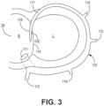
- FIG. 3 illustrates the coronary vein anatomy with various regions of the great cardiac vein 110 depicted to illustrate the location of at least one septal perforating vein 118 into which the pacing lead is positioned.
- the great cardiac vein 110 extends from the coronary sinus ostium 111 defined by the wall of the right atrium 26 and past the middle cardiac vein 113, the posterolateral vein 114, the lateral vein 115, the anterolateral vein 116, and the anterior interventricular vein 117.
- the anterior interventricular vein 117 then branches off into at least one septal perforating vein 118 proximate the ventricular septum 119.
- the at least one septal perforating vein 118 may provide access to an implant region 102 proximate the bundle branches of the heart such that a pacing lead may deliver pacing therapy thereto.
- the coronary venous system may be injected with a contrast agent such that the characteristics and/or regions of the great cardiac vein 110 may be identified via imaging.
- the systems, devices, and methods described herein include delivering a pacing lead deeper into the coronary venous system, therefore, typically-used contrast injections may be insufficient.
- typically-used contrast injections may not be able to inject contrast agent into the septal perforating vein or may need to deliver a higher-pressure, larger dose of contrast agent to ensure that the contrast agent enters the septal perforating vein. Both scenarios may be undesirable because either the septal perforating vein is not illuminated for positioning the pacing lead or the increased dose of contrast agent may be less optimal for the patient.
- a catheter 130 may be used to navigate the great cardiac vein 110 and inject a contrast agent to help locate an implant region within the at least one septal perforating vein 118.
- the catheter may be positioned at one or more positions within the great cardiac vein 110 to inject relatively small doses of contrast (e.g., less than or equal to 10 milliliters) to identify the implant region.
- the contrast agent may be injected at a first position within the great cardiac vein 110 and if the implant region (e.g., within the septal perforating vein 118) is properly illuminated/identified, the procedure may continue (e.g., by inserting a pacing lead to the implant region). However, if the implant region is not properly illuminated/identified, the catheter may be moved to another location to inject the contrast agent. The catheter may be moved to one or more positions, injecting the contrast agent at each position, to illuminate and identify the implant region.
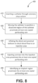
- the method 300 of implanting a pacing lead in a patient's heart may include inserting 310 a catheter (e.g., catheter 130 illustrated in FIG. 6 ) through the coronary sinus ostium of the patient's heart. Further, the method 300 may include moving 320 the catheter to position a distal end region of the catheter into the great cardiac vein past the anterolateral vein of the patient to one or more positions proximate at least one septal perforating vein of the patient.
- a catheter e.g., catheter 130 illustrated in FIG. 6
- the method 300 may include moving 320 the catheter to position a distal end region of the catheter into the great cardiac vein past the anterolateral vein of the patient to one or more positions proximate at least one septal perforating vein of the patient.
- the method 300 may also include injecting 330 contrast out of the distal end region of the catheter into an injection area of each of the one or more positions proximate the at least one septal perforating vein and identifying 340 an implant region proximate the at least one septal perforating vein. Therefore, the catheter may be moved to one or more positions to inject contrast in an effort to identify the implant region. In one or more embodiments, the catheter may be moved to a plurality of distinct positions within the great cardiac vein.
- the user may be able to create a great cardiac vein map to help visualize the at least one septal perforating vein.
- multiple mini-venograms may be produced from imaging of the heart while injecting contrast agent at the one or more positions.
- the mini-venograms may be combined or stitched together to form a larger picture of the coronary venous system.
- software may be used to form a single, complete venogram that may, in one or more embodiments, serve as a "roadmap" throughout the procedure.
- the method 300 may include removing 350 the catheter and moving 360 a pacing lead to the implant region to deliver pacing therapy thereto.
- the pacing lead may be inserted through the great cardiac vein to the implant region (e.g., using visual images generated from the injection of the contrast agent therein).
- the implant region may provide cardiac conduction system pacing such that the pacing lead may deliver pacing to the cardiac conduction system pacing of the heart at the implant region.
- the implant region may be proximate the His bundle such that the pacing lead may deliver His bundle pacing to the implant region. In one or more embodiments, the implant region may be proximate the left bundle branch pacing such that the pacing lead delivers left bundle branch pacing to the implant region. In other embodiments, the implant region may provide traditional cardiac pacing. For example, in an ovine study, cardiac conduction system pacing from the septal perforating vein may be achieved with about a 2.0V threshold, impedance of about 362 ohms, and a current of about 7.0 mA. Further, in one or more embodiments, cardiac conduction system pacing from the septal perforating vein may be achieved with about a 1.8V threshold, an R-wave of about 1.4 mV, and a pulse width of about 0.4 ms.
- the method may further include generating a cardiac map of electrical activation based on a plurality of electrode signals monitored using a plurality of external electrodes proximate the skin on the patient such as, e.g., described in U.S. Provisional Patent Application Serial No. 62/844,489 filed on May 7, 2019 , entitled "Supplementation of Cardiac Conduction System Pacing Therapy.”
- the operability of the pacing lead may be verified after the pacing lead is positioned within the heart using various systems such as those that provide cardiac maps of electrical activation.
- electrical activation mapping may be provided using, e.g., ECG, Vectorcardiography, 3D electrical mapping, etc.
- electrical activation mapping may be provided by software including, e.g., CardioInsight, Ensite, and CARTO.
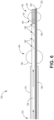
- the catheter 130 may include an elongate housing 131 extending between a proximal end region 133 (e.g., including a proximal end) and a distal end region 132 (e.g., including a distal end 137). It is noted that the proximal end of the catheter 130 may be out of frame in FIG. 6 , but the most proximal portion of the catheter is denoted with reference numeral 133 (e.g., even though the proximal end region 133 may also be out of frame).
- the elongate housing 131 of the catheter 130 may be positionable in the great cardiac vein such that the distal end region 132 may be located past the anterolateral vein of the patient proximate at least one septal perforating vein of the patient.
- the catheter 130 may comprise various specific materials and define a relatively small size.
- the elongate housing 131 may include (e.g., be formed of) any suitable materials such as, e.g., polyurethane, silicone, a hybrid of polyurethane and silicone, etc.
- the elongate housing 131 may define any suitable cross-sectional diameter.
- the elongate housing 131 may define a cross-sectional diameter such that the catheter 130 may be inserted into the great cardiac vein proximate the at least one septal perforating vein.
- Such cross-sectional diameter of the elongate housing 131 may be smaller than many other traditionally-used catheters because, for example, the amount of space in the great cardiac vein proximate the at least one septal perforating vein may be substantially smaller than where traditional catheters and/or leads have been navigated and/or placed within the venous system.
- the elongate housing 131 may define a lumen 134 extending therethrough (e.g., between the distal and proximal end regions 132, 133). Further, the elongate housing 131 may define one or more side openings 136 extending through an outer surface 139 of the elongate housing 131 in the distal end region 132 of the elongate housing 131 and in fluid communication with the lumen 134.
- the catheter 130 may be configured such that contrast may be injected through the one or more side openings 136 (e.g., from the lumen 134) of the elongate housing 131 into an injection area proximate the at least one septal perforating vein.
- the openings through which contrast is injected is described as "side" openings, in one or more embodiments, the openings through which contrast is injected may be located at the distal end of the elongate housing 131.
- the catheter 130 may include at least two inflatable balloons 140 positioned on (e.g., near, proximate, etc.) the distal end region 132 of the elongate housing 131.
- the at least two inflatable balloons 140 may include a first inflatable balloon 141 positioned distally of the one or more side openings 136 and a second inflatable balloon 142 positioned proximally of the one or more side openings 136.
- the first inflatable balloon 141 may be located closer to the distal end 137 than the second inflatable balloon 142.
- the one or more side openings 136 may include multiple openings between the first and second balloons 141, 142.
- the at least two inflatable balloons 140 may be configured to inflate to block blood flow in the great cardiac vein to the injection area between the first and second balloons 141, 142 prior to injecting contrast into the injection area.
- the elongate housing 131 may further define a bypass lumen that is configured to allow blood to pass through the catheter 130 without interfering with the contrast injection through the one or more side openings 136.
- the at least two inflatable balloons 140 may include (e.g., be formed of) any suitable material such as, e.g., a compliant material.
- the at least two inflatable balloons 140 may define any suitable diameter when inflated.
- the first balloon 141 may define a first diameter when inflated and the second balloon 142 may define a second diameter when inflated, the first diameter being the same as or different from the second diameter.
- the first diameter and/or second diameter may be any suitable diameter.
- the first diameter may be smaller than the second diameter (e.g., because the first balloon 141 may be deeper inside the vein due to its distal location on the elongate housing 131).
- the first and second inflatable balloons 141, 142 may be separated by any suitable distance along the elongate housing 131.
- the first and second inflatable balloons 141, 142 may be spaced apart by about 0.5 inches to 1 inch (e.g., measured between the closest portions of the first and second inflatable balloons 141, 142).
- the distance between the at least two inflatable balloons 140 may determine the precision of the catheter 130 when injecting contrast to identify the at least one septal perforating vein. For example, if the balloons are closer together, the contrast may be injected with a more targeted approach and, e.g., use less contrast agent. If the balloons are farther apart, the contrast may be injected with a wider scope but may use more contrast agent.
- the catheter 130 may include more than two inflatable balloons.
- the at least two inflatable balloons 140 may include a third balloon and a fourth balloon.
- the third balloon may be positioned along the elongate housing 131 more proximal than the second balloon 142, and the fourth balloon more proximal than the third balloon.
- the third and fourth balloons may have similar characteristics as described in connection with the first and second balloons 141, 142 (e.g., size, material, spacing).
- the one or more side openings 136 may include a first opening located between the first and second balloons 141, 142 and a second opening located between the third and fourth balloons.
- the contrast agent may be injected through both of the first and second openings to assist in identifying the implant region.
- the at least two inflatable balloons 140 may include any suitable number of balloons in any suitable arrangement (e.g., three inflatable balloons with an opening between the first and second balloons and another opening between the second and third balloons).
- the catheter 130 may include one or more markers disposed on the elongate housing 131 such that portions of the catheter 130 may be identified using imaging during a procedure.
- the catheter 130 may include any type of marker such as, e.g., a radiopaque marker, a directional marker, a mapping electrode, any suitable fluoro-visible marker, etc.
- the one or more markers may be positioned at any suitable location along the elongate housing 131.
- the catheter 130 may include at least one marker associated with each inflatable balloon (e.g., on either side of each balloon) such that the balloons are easily identifiable using imaging.
- the one or more markers may be located along the elongate housing 131 to help identify an opening through which contrast or a guide wire may extend.
- the elongate housing 131 of the catheter 130 may define a guide wire lumen 150 and the catheter 130 may include a guide wire 152 configured to extend through the guide wire lumen 150.
- the guide wire 152 may be used to help position the pacing lead within the at least one septal perforating vein after the implant region is identified.
- a guide wire 152 may be inserted through the catheter 130 (e.g., through the guide wire lumen 150) into position proximate the identified implant region before the catheter 130 is removed from the great cardiac vein (e.g., while the guide wire 152 is retained proximate the septal perforating vein).
- the pacing lead may be moved to the implant region using the guide wire 152 (e.g., the pacing lead may be guided along the guide wire 152).
- the elongate housing 131 may define a guide wire opening 154 extending through the outer surface 139 of the elongate housing 131 and in fluid communication with the guide wire lumen 150 such that the guide wire 152 exits the guide wire lumen 150 through the guide wire opening 154. Because the guide wire 152 may be used to assist in guiding the pacing lead into the at least one septal perforating vein, it may be desirable to align the guide wire 152 with the at least one septal perforating vein. In one or more embodiments, the guide wire opening 154 may be positioned between the first and second balloons 141, 142.
- the guidewire opening 154 may be positioned such that the opening is aligned with the at least one septal perforating vein (e.g., using the one or more markers). Therefore, the guide wire 152 may exit the guide wire opening 154 directly into the at least one septal perforating vein.
- the guide wire opening 154 may be positioned at the distal end of the elongate housing 131 (e.g., as shown in FIG. 6 ) such that the guide wire 152 may exit the distal end of the elongate housing 131.
- the guide wire 152 may be pulled proximally by a set distance (e.g., to clear the branch vein of interest) such that the guide wire 152 may be aligned with the at least one septal perforating vein (e.g., so that the pacing lead may be directed therein).
- the catheter 130 may be used to navigate the coronary venous system (e.g., into the at least one septal perforating vein).
- the distal end region 132 of the catheter 130 may define a spiral tip to, e.g., navigate the at least one septal perforating vein.
- the spiral tip may utilize a rotate-to-advance principle similar to an Archimedes' screw, but where the auger advances as it is rotated.
- an actively steerable catheter may be used to navigate the at least one septal perforating vein.
- the actively steerable catheter may be inserted through the great cardiac vein using the guide wire 152 to the at least one septal perforating vein. Thereafter, the actively steerable catheter may be used to navigate the at least one septal perforating vein to the implant region (e.g., using imaging of the vein, which may be illuminated due to the contrast agent injected therein).
- the actively steerable catheter may include any catheter designed such that the distal tip deflects at the direction of the user to navigate a vessel (e.g., tortuous path of a vein).
- the method 400 may include inserting 410 the catheter through the coronary sinus ostium of the patient's heart. Further, the method 400 may include moving 420 the catheter to position a distal end region of the catheter into the great cardiac vein past the anterolateral vein of the patient to one or more positions proximate at least one septal perforating vein of the patient.
- the catheter may include a distal balloon (e.g., the first balloon 141) and a proximal balloon (e.g., the second balloon 142) positioned on the distal end region, as described herein in connection with FIG. 6 .
- the distal balloon may be located more distally than the proximal balloon.
- the method 400 may also include inflating 430 the distal and proximal balloons to block blood flow to an injection area between the distal and proximal balloons at each of the one or more positions.
- the method 400 may include injecting 440 contrast out of the distal end region (e.g., through the one or more side openings 136) of the catheter into the injection area of each of the one or more positions proximate the at least one septal perforating vein and identifying 450 an implant region proximate the at least one septal perforating vein (e.g., such that the pacing lead can be positioned at the identified implant region as described herein).
- the illustrative methods may include moving the catheter to one or more positions because it may take one or more placements and injections of contrast to identify the implant region proximate the at least one septal perforating vein.
- the catheter may be moved and the contrast agent injected into the vein multiple times before the implant region is identified.
- the distal and proximal balloons may be deflated and the catheter may be moved to another position of the one or more positions.
- distal and proximal balloons may be inflated again to block blood flow to another injection area between the balloons and contrast may be injected into the injection area of the another position of the one or more positions proximate the at least one septal perforating vein.
- the user may generate images of the coronary venous system as a preliminary view for helping navigate with the catheter to, e.g., help determine where to further inject contrast to identify the implant region proximate the at least one septal perforating vein.
- Generating an image of the patient's heart may be done in any suitable way.
- the image of the patient's heart may be generated using a CT/MR angiography scope, rotational angiography, ultrasound, x-ray, etc.
- CT computed tomography
- REO right anterior oblique
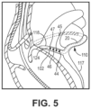
- FIG. 5 e.g., an expanded view of FIG. 2
- the pacing lead 20 may extend between a proximal end region 122 (e.g., proximate the IMD 16 illustrated in FIG. 2 ) and a distal end region 124.
- the pacing lead 20 may include a plurality of electrodes (e.g., electrodes 44, 45, 46, 47) proximate the distal end region 124.
- the distal end region 124 of the pacing lead 20 may be positionable in an implant region proximate at least one septal perforating vein 118 of a patient's heart. Specifically, the electrodes may be spaced for efficiently capturing both the right and left bundle branches from the septal perforating vein 118.
- the distal end region 124 of the pacing lead 20 may define any suitable cross-sectional diameter.
- the cross-sectional diameter of the distal end region 124 of the pacing lead 20 may sized to be inserted into the at least one septal perforating vein 118 such that the electrodes may be proximate the implant region.
- the distal end region 124 of the pacing lead 20 may define a cross-sectional diameter of about less than or equal to 1 millimeter. More specifically, the pacing lead may be described as a 1-3 French (Fr) lead.
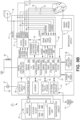
- FIG. 9A is a functional block diagram of one illustrative configuration of the IMD 16.
- the IMD 16 may include a control module 81 (e.g., a controller), a therapy delivery module 84 (e.g., which may include a stimulation generator), a sensing module 86, and a power source 90.
- the control module 81 may be operably coupled to the pacing lead 20 and may be configured to deliver pacing therapy to the implant region proximate the at least one septal perforating vein of the patient's heart using at least one electrode of the plurality of electrodes of the pacing lead 20.
- the control module, or apparatus, 81 may include a processor 80, memory 82, and a telemetry module, or apparatus, 88.
- the memory 82 may include computer-readable instructions that, when executed, e.g., by the processor 80, cause the IMD 16 and/or the control module 81 to perform various functions attributed to the IMD 16 and/or the control module 81 described herein.
- the memory 82 may include any volatile, non-volatile, magnetic, optical, and/or electrical media, such as a random-access memory (RAM), read-only memory (ROM), non-volatile RAM (NVRAM), electrically-erasable programmable ROM (EEPROM), flash memory, and/or any other digital media.
- An illustrative capture management module may be the left ventricular capture management (LVCM) module described in U.S. Pat. No. 7,684,863 entitled "LV THRESHOLD MEASUREMENT AND CAPTURE MANAGEMENT” and issued March 23, 2010 .
- LVCM left ventricular capture management
- the processor 80 of the control module 81 may include any one or more of a microprocessor, a controller, a digital signal processor (DSP), an application specific integrated circuit (ASIC), a field-programmable gate array (FPGA), and/or equivalent discrete or integrated logic circuitry.
- the processor 80 may include multiple components, such as any combination of one or more microprocessors, one or more controllers, one or more DSPs, one or more ASICs, and/or one or more FPGAs, as well as other discrete or integrated logic circuitry.
- the functions attributed to the processor 80 herein may be embodied as software, firmware, hardware, or any combination thereof.
- the control module 81 may control the therapy delivery module 84 to deliver therapy (e.g., electrical stimulation therapy such as pacing) to the heart 12 according to a selected one or more therapy programs, which may be stored in the memory 82. More, specifically, the control module 81 (e.g., the processor 80) may control various parameters of the electrical stimulus delivered by the therapy delivery module 84 such as, e.g., A-V delays, V-V delays, pacing pulses with the amplitudes, pulse widths, frequency, or electrode polarities, etc., which may be specified by one or more selected therapy programs (e.g., A-V and/or V-V delay adjustment programs, pacing therapy programs, pacing recovery programs, capture management programs, etc.).
- therapy programs e.g., electrical stimulation therapy such as pacing
- the therapy delivery module 84 is electrically coupled to electrodes 40, 42, 44, 45, 46, 47, 48, 50, 58, 62, 64, 66, e.g., via conductors of the respective lead 18, 20, 22, or, in the case of housing electrode 58, via an electrical conductor disposed within housing 60 of IMD 16.
- Therapy delivery module 84 may be configured to generate and deliver electrical stimulation therapy such as pacing therapy to the heart 12 using one or more of the electrodes 40, 42, 44, 45, 46, 47, 48, 50, 58, 62, 64, 66.
- the therapy delivery module 84 may be configured to generate and deliver electrical stimulation therapy such as cardiac conduction system pacing therapy to the cardiac conduction system of the heart 12 using one or more of the electrodes 44, 45, 46, 47.
- the therapy delivery module 84 may be configured to generate and deliver electrical stimulation therapy such as traditional cardiac pacing therapy to the heart 12 using one or more of the electrodes 44, 45, 46, 47.
- therapy delivery module 84 may deliver pacing stimulus (e.g., pacing pulses) via ring electrodes 40, 44, 45, 46, 47, 48 coupled to leads 18, 20, 22 and/or helical tip electrodes 42, 50 of leads 18, 22. Further, for example, therapy delivery module 84 may deliver defibrillation shocks to heart 12 via at least two of electrodes 58, 62, 64, 66. In some examples, therapy delivery module 84 may be configured to deliver pacing, cardioversion, or defibrillation stimulation in the form of electrical pulses. In other examples, therapy delivery module 84 may be configured deliver one or more of these types of stimulation in the form of other signals, such as sine waves, square waves, and/or other substantially continuous time signals.
- pacing stimulus e.g., pacing pulses
- therapy delivery module 84 may deliver defibrillation shocks to heart 12 via at least two of electrodes 58, 62, 64, 66.
- therapy delivery module 84 may be configured to deliver pac
- the IMD 16 may further include a switch module 85 and the control module 81 (e.g., the processor 80) may use the switch module 85 to select, e.g., via a data/address bus, which of the available electrodes are used to deliver therapy such as pacing pulses for pacing therapy, or which of the available electrodes are used for sensing.
- the switch module 85 may include a switch array, switch matrix, multiplexer, or any other type of switching device suitable to selectively couple the sensing module 86 and/or the therapy delivery module 84 to one or more selected electrodes. More specifically, the therapy delivery module 84 may include a plurality of pacing output circuits.
- Each pacing output circuit of the plurality of pacing output circuits may be selectively coupled, e.g., using the switch module 85, to one or more of the electrodes 40, 42, 44, 45, 46, 47, 48, 50, 58, 62, 64, 66 (e.g., a pair of electrodes for delivery of therapy to a bipolar or multipolar pacing vector).
- each electrode can be selectively coupled to one of the pacing output circuits of the therapy delivery module using the switching module 85.
- the sensing module 86 is coupled (e.g., electrically coupled) to sensing apparatus, which may include, among additional sensing apparatus, the electrodes 40, 42, 44, 45, 46, 47, 48, 50, 58, 62, 64, 66 to monitor electrical activity of the heart 12, e.g., electrocardiogram (ECG)/electrogram (EGM) signals, etc.
- ECG electrocardiogram
- EMG electrocardiogram
- EMG electrocardiogram
- ECM electrocardiogram
- the ECG/EGM signals may be used to measure or monitor activation times (e.g., ventricular activations times, etc.), heart rate (HR), heart rate variability (HRV), heart rate turbulence (HRT), deceleration/acceleration capacity, deceleration sequence incidence, T-wave alternans (TWA), P-wave to P-wave intervals (also referred to as the P-P intervals or A-A intervals), R-wave to R-wave intervals (also referred to as the R-R intervals or V-V intervals), P-wave to QRS complex intervals (also referred to as the P-R intervals, A-V intervals, or P-Q intervals), QRS-complex morphology, ST segment (i.e., the segment that connects the QRS complex and the T-wave), T-wave changes, QT intervals, electrical vectors, etc.
- activation times e.g., ventricular activations times, etc.
- HR heart rate
- HRV heart rate variability
- HRT
- the switch module 85 may also be used with the sensing module 86 to select which of the available electrodes are used, or enabled, to, e.g., sense electrical activity of the patient's heart (e.g., one or more electrical vectors of the patient's heart using any combination of the electrodes 40, 42, 44, 45, 46, 47, 48, 50, 58, 62, 64, 66).
- sense electrical activity of the patient's heart e.g., one or more electrical vectors of the patient's heart using any combination of the electrodes 40, 42, 44, 45, 46, 47, 48, 50, 58, 62, 64, 66.
- the switch module 85 may also be used with the sensing module 86 to select which of the available electrodes are not to be used (e.g., disabled) to, e.g., sense electrical activity of the patient's heart (e.g., one or more electrical vectors of the patient's heart using any combination of the electrodes 40, 42, 44, 45, 46, 47, 48, 50, 58, 62, 64, 66), etc.
- the control module 81 may select the electrodes that function as sensing electrodes via the switch module within the sensing module 86, e.g., by providing signals via a data/address bus.
- sensing module 86 includes a channel that includes an amplifier with a relatively wider pass band than the R-wave or P-wave amplifiers. Signals from the selected sensing electrodes may be provided to a multiplexer, and thereafter converted to multi-bit digital signals by an analog-to-digital converter for storage in memory 82, e.g., as an electrogram (EGM). In some examples, the storage of such EGMs in memory 82 may be under the control of a direct memory access circuit.
- EGM electrogram
- control module 81 may operate as an interrupt-driven device and may be responsive to interrupts from pacer timing and control module, where the interrupts may correspond to the occurrences of sensed P-waves and R-waves and the generation of cardiac pacing pulses. Any necessary mathematical calculations may be performed by the processor 80 and any updating of the values or intervals controlled by the pacer timing and control module may take place following such interrupts.
- a portion of memory 82 may be configured as a plurality of recirculating buffers, capable of holding one or more series of measured intervals, which may be analyzed by, e.g., the processor 80 in response to the occurrence of a pace or sense interrupt to determine whether the patient's heart 12 is presently exhibiting atrial or ventricular tachyarrhythmia.
- the telemetry module 88 of the control module 81 may include any suitable hardware, firmware, software, or any combination thereof for communicating with another device, such as a programmer.
- the telemetry module 88 may receive downlink telemetry from and send uplink telemetry to a programmer with the aid of an antenna, which may be internal and/or external.
- the processor 80 may provide the data to be uplinked to a programmer and the control signals for the telemetry circuit within the telemetry module 88, e.g., via an address/data bus.
- the telemetry module 88 may provide received data to the processor 80 via a multiplexer.
- the various components of the IMD 16 are further coupled to a power source 90, which may include a rechargeable or non-rechargeable battery.
- a power source 90 may include a rechargeable or non-rechargeable battery.
- a non-rechargeable battery may be selected to last for several years, while a rechargeable battery may be inductively charged from an external device, e.g., on a daily or weekly basis.
- FIG. 9B is another embodiment of a functional block diagram for IMD 16 that depicts bipolar RA lead 22, bipolar RV lead 18, and bipolar LV CS lead 20 without the LA CS pace/sense electrodes and coupled with an implantable pulse generator (IPG) circuit 31 having programmable modes and parameters of a bi-ventricular DDD/R type known in the pacing art.
- the sensor signal processing circuit 91 indirectly couples to the timing circuit 43 and via data and control bus to microcomputer circuitry 33.
- the IPG circuit 31 is illustrated in a functional block diagram divided generally into a microcomputer circuit 33 and a pacing circuit 21.
- the pacing circuit 21 includes the digital controller/timer circuit 43, the output amplifiers circuit 51, the sense amplifiers circuit 55, the RF telemetry transceiver 41, the activity sensor circuit 35 as well as a number of other circuits and components described below.
- Crystal oscillator circuit 89 provides the basic timing clock for the pacing circuit 21 while battery 29 provides power.
- Power-on-reset circuit 87 responds to initial connection of the circuit to the battery for defining an initial operating condition and similarly, resets the operative state of the device in response to detection of a low battery condition.
- Reference mode circuit 37 generates stable voltage reference and currents for the analog circuits within the pacing circuit 21.
- Analog-to-digital converter (ADC) and multiplexer circuit 39 digitize analog signals and voltage to provide, e.g., real time telemetry of cardiac signals from sense amplifiers 55 for uplink transmission via RF transmitter and receiver circuit 41.
- Voltage reference and bias circuit 37, ADC and multiplexer 39, power-on-reset circuit 87, and crystal oscillator circuit 89 may correspond to any of those used in illustrative implantable cardiac pacemakers.
- the signals output by one or more physiologic sensors are employed as a rate control parameter (RCP) to derive a physiologic escape interval.
- RCP rate control parameter
- the escape interval is adjusted proportionally to the patient's activity level developed in the patient activity sensor (PAS) circuit 35 in the depicted, illustrative IPG circuit 31.
- the patient activity sensor 27 is coupled to the IPG housing and may take the form of a piezoelectric crystal transducer.
- the output signal of the patient activity sensor 27 may be processed and used as an RCP.
- Sensor 27 generates electrical signals in response to sensed physical activity that are processed by activity circuit 35 and provided to digital controller/timer circuit 43.
- Activity circuit 35 and associated sensor 27 may correspond to the circuitry disclosed in U.S.
- Uplink telemetry capabilities may include the ability to transmit stored digital information, e.g., operating modes and parameters, EGM histograms, and other events, as well as real time EGMs of atrial and/or ventricular electrical activity and marker channel pulses indicating the occurrence of sensed and paced depolarizations in the atrium and ventricle.
- Microcomputer 33 contains a microprocessor 80 and associated system clock and on-processor RAM and ROM chips 82A and 82B, respectively.
- microcomputer circuit 33 includes a separate RAM/ROM chip 82C to provide additional memory capacity.
- Microprocessor 80 normally operates in a reduced power consumption mode and is interrupt driven. Microprocessor 80 is awakened in response to defined interrupt events, which may include A-TRIG, RV-TRIG, LV-TRIG signals generated by timers in digital timer/controller circuit 43 and A-EVENT, RV-EVENT, and LV-EVENT signals generated by sense amplifiers circuit 55, among others.
- the specific values of the intervals and delays timed out by digital controller/timer circuit 43 are controlled by the microcomputer circuit 33 by way of data and control bus from programmed-in parameter values and operating modes.
- a timed interrupt e.g., every cycle or every two seconds, may be provided in order to allow the microprocessor to analyze the activity sensor data and update the basic A-A, V-A, or V-V escape interval, as applicable.
- the microprocessor 80 may also serve to define variable, operative A-V delay intervals, V-V delay intervals, and the energy delivered to each ventricle and/or atrium.
- microprocessor 80 is a custom microprocessor adapted to fetch and execute instructions stored in RAM/ROM unit 82 in a conventional manner. It is contemplated, however, that other implementations may be suitable to practice the present disclosure. For example, an off-the-shelf, commercially available microprocessor or microcontroller, or custom application-specific, hardwired logic, or state-machine type circuit may perform the functions of microprocessor 80.
- Digital controller/timer circuit 43 operates under the general control of the microcomputer 33 to control timing and other functions within the pacing circuit 21 and includes a set of timing and associated logic circuits of which certain ones pertinent to the present disclosure are depicted.
- the depicted timing circuits include URI/LRI timers 83A, V-V delay timer 83B, intrinsic interval timers 83C for timing elapsed V-EVENT to V-EVENT intervals or V-EVENT to A-EVENT intervals or the V-V conduction interval, escape interval timers 83D for timing A-A, V-A, and/or V-V pacing escape intervals, an A-V delay interval timer 83E for timing the A-LVp delay (or A-RVp delay) from a preceding A-EVENT or A-TRIG, a post-ventricular timer 83F for timing post-ventricular time periods, and a date/time clock 83G.
- the A-V delay interval timer 83E is loaded with an appropriate delay interval for one ventricular chamber (e.g., either an A-RVp delay or an A-LVp) to time-out starting from a preceding A-PACE or A-EVENT.
- the interval timer 83E triggers pacing stimulus delivery and can be based on one or more prior cardiac cycles (or from a data set empirically derived for a given patient).
- the post-event timer 83F times out the post-ventricular time period following an RV-EVENT or LV-EVENT or a RV-TRIG or LV-TRIG and post-atrial time periods following an A-EVENT or A-TRIG.
- the durations of the post-event time periods may also be selected as programmable parameters stored in the microcomputer 33.
- the post-ventricular time periods include the PVARP, a post-atrial ventricular blanking period (PAVBP), a ventricular blanking period (VBP), a post-ventricular atrial blanking period (PVARP) and a ventricular refractory period (VRP) although other periods can be suitably defined depending, at least in part, on the operative circuitry employed in the pacing engine.
- the post-atrial time periods include an atrial refractory period (ARP) during which an A-EVENT is ignored for the purpose of resetting any A-V delay, and an atrial blanking period (ABP) during which atrial sensing is disabled.
- ARP atrial refractory period
- ABP atrial blanking period
- the starting of the post-atrial time periods and the A-V delays can be commenced substantially simultaneously with the start or end of each A-EVENT or A-TRIG or, in the latter case, upon the end of the A-PACE which may follow the A-TRIG.
- the starting of the post-ventricular time periods and the V-A escape interval can be commenced substantially simultaneously with the start or end of the V-EVENT or V-TRIG or, in the latter case, upon the end of the V-PACE which may follow the V-TRIG.
- the microprocessor 80 also optionally calculates A-V delays, V-V delays, post-ventricular time periods, and post-atrial time periods that vary with the sensor-based escape interval established in response to the RCP(s) and/or with the intrinsic atrial and/or ventricular rate.
- the output amplifiers circuit 51 contains a RA pace pulse generator (and a LA pace pulse generator if LA pacing is provided), a RV pace pulse generator, a LV pace pulse generator, and/or any other pulse generator configured to provide atrial and ventricular pacing.
- digital controller/timer circuit 43 In order to trigger generation of an RV-PACE or LV-PACE pulse, digital controller/timer circuit 43 generates the RV-TRIG signal at the time-out of the A-RVp delay (in the case of RV pre-excitation) or the LV-TRIG at the time-out of the A-LVp delay (in the case of LV pre-excitation) provided by A-V delay interval timer 83E (or the V-V delay timer 83B).
- digital controller/timer circuit 43 generates an RA-TRIG signal that triggers output of an RA-PACE pulse (or an LA-TRIG signal that triggers output of an LA-PACE pulse, if provided) at the end of the V-A escape interval timed by escape interval timers 83D.
- the output amplifiers circuit 51 includes switching circuits for coupling selected pace electrode pairs from among the lead conductors and the IND-CAN electrode 20 to the RA pace pulse generator (and LA pace pulse generator if provided), RV pace pulse generator and LV pace pulse generator.
- Pace/sense electrode pair selection and control circuit 53 selects lead conductors and associated pace electrode pairs to be coupled with the atrial and ventricular output amplifiers within output amplifiers circuit 51 for accomplishing RA, LA, RV and LV pacing.
- the sense amplifiers circuit 55 contains sense amplifiers for atrial and ventricular pacing and sensing.
- High impedance P-wave and R-wave sense amplifiers may be used to amplify a voltage difference signal that is generated across the sense electrode pairs by the passage of cardiac depolarization wavefronts.
- the high impedance sense amplifiers use high gain to amplify the low amplitude signals and rely on pass band filters, time domain filtering and amplitude threshold comparison to discriminate a P-wave or R-wave from background electrical noise.
- Digital controller/timer circuit 43 controls sensitivity settings of the atrial and ventricular sense amplifiers 55.
- the sense amplifiers may be uncoupled from the sense electrodes during the blanking periods before, during, and after delivery of a pace pulse to any of the pace electrodes of the pacing system to avoid saturation of the sense amplifiers.
- the sense amplifiers circuit 55 includes blanking circuits for uncoupling the selected pairs of the lead conductors and the IND-CAN electrode 20 from the inputs of the RA sense amplifier (and LA sense amplifier if provided), RV sense amplifier and LV sense amplifier during the ABP, PVABP and VBP.
- the sense amplifiers circuit 55 also includes switching circuits for coupling selected sense electrode lead conductors and the IND-CAN electrode 20 to the RA sense amplifier (and LA sense amplifier if provided), RV sense amplifier and LV sense amplifier.
- sense electrode selection and control circuit 53 selects conductors and associated sense electrode pairs to be coupled with the atrial and ventricular sense amplifiers within the output amplifiers circuit 51 and sense amplifiers circuit 55 for accomplishing RA, LA, RV, and LV sensing along desired unipolar and bipolar sensing vectors.
- RA-SENSE signal Right atrial depolarizations or P-waves in the RA-SENSE signal that are sensed by the RA sense amplifier result in a RA-EVENT signal that is communicated to the digital controller/timer circuit 43.
- left atrial depolarizations or P-waves in the LA-SENSE signal that are sensed by the LA sense amplifier result in a LA-EVENT signal that is communicated to the digital controller/timer circuit 43.
- Ventricular depolarizations or R-waves in the RV-SENSE signal are sensed by a ventricular sense amplifier result in an RV-EVENT signal that is communicated to the digital controller/timer circuit 43.
- ventricular depolarizations or R-waves in the LV-SENSE signal are sensed by a ventricular sense amplifier result in an LV-EVENT signal that is communicated to the digital controller/timer circuit 43.
- the RV-EVENT, LV-EVENT, and RA-EVENT, LA-SENSE signals may be refractory or non-refractory and can inadvertently be triggered by electrical noise signals or aberrantly conducted depolarization waves rather than true R-waves or P-waves.
- the techniques described in this disclosure may be implemented, at least in part, in hardware, software, firmware, or any combination thereof.
- various aspects of the techniques may be implemented within one or more processors, including one or more microprocessors, DSPs, ASICs, FPGAs, or any other equivalent integrated or discrete logic circuitry, as well as any combinations of such components, embodied in programmers, such as physician or patient programmers, stimulators, image processing devices, or other devices.
- the term "module,” “processor,” or “processing circuitry” may generally refer to any of the foregoing logic circuitry, alone or in combination with other logic circuitry, or any other equivalent circuitry.
- Such hardware, software, and/or firmware may be implemented within the same device or within separate devices to support the various operations and functions described in this disclosure.
- any of the described units, modules, or components may be implemented together or separately as discrete but interoperable logic devices. Depiction of different features as modules or units is intended to highlight different functional aspects and does not necessarily imply that such modules or units must be realized by separate hardware or software components. Rather, functionality associated with one or more modules or units may be performed by separate hardware or software components or integrated within common or separate hardware or software components.
- the functionality ascribed to the systems, devices and techniques described in this disclosure may be embodied as instructions on a computer-readable medium such as RAM, ROM, NVRAM, EEPROM, FLASH memory, magnetic data storage media, optical data storage media, or the like.
- the instructions may be executed by processing circuitry and/or one or more processors to support one or more aspects of the functionality described in this disclosure.
Landscapes
- Health & Medical Sciences (AREA)
- Life Sciences & Earth Sciences (AREA)
- Engineering & Computer Science (AREA)
- Heart & Thoracic Surgery (AREA)
- Public Health (AREA)
- General Health & Medical Sciences (AREA)
- Veterinary Medicine (AREA)
- Animal Behavior & Ethology (AREA)
- Biomedical Technology (AREA)
- Nuclear Medicine, Radiotherapy & Molecular Imaging (AREA)
- Radiology & Medical Imaging (AREA)
- Biophysics (AREA)
- Medical Informatics (AREA)
- Physics & Mathematics (AREA)
- Molecular Biology (AREA)
- Surgery (AREA)
- Pathology (AREA)
- Cardiology (AREA)
- Anesthesiology (AREA)
- Hematology (AREA)
- Pulmonology (AREA)
- High Energy & Nuclear Physics (AREA)
- Vascular Medicine (AREA)
- Optics & Photonics (AREA)
- Dentistry (AREA)
- Oral & Maxillofacial Surgery (AREA)
- Computer Vision & Pattern Recognition (AREA)
- Theoretical Computer Science (AREA)
- Child & Adolescent Psychology (AREA)
- Hospice & Palliative Care (AREA)
- Electrotherapy Devices (AREA)
Claims (8)
- System zum Abgeben einer Schrittmachertherapie an das Herz eines Patienten, das System umfassend:einen Katheter (130), umfassend ein längliches Gehäuse (131), das sich zwischen einer proximalen Endregion (133) und einer distalen Endregion (132) erstreckt, wobei das längliche Gehäuse ein sich hindurch erstreckendes Lumen (131) definiert, wobei der Katheter konfiguriert ist, um durch das Koronarvenensinusostium (111) des Herzens eines Patienten eingeführt zu werden, derart, dass die distale Endregion des Katheters in der großen Herzvene (110) hinter der anterolateralen Vene (116) des Patienten in der Nähe von mindestens einer Septumperforationsvene (118) des Herzens des Patienten positioniert ist, wobei der Katheter ferner konfiguriert ist, um Kontrast in einen Injektionsbereich in der Nähe der mindestens einen Septumperforationsvene zu injizieren;eine Schrittmacherleitung (20), die sich zwischen einer proximalen Endregion (122) und einer distalen Endregion (124) erstreckt, wobei die Schrittmacherleitung eine Vielzahl von Elektroden (44, 45, 46, 47) in der Nähe der distalen Endregion umfasst, wobei die distale Endregion der Schrittmacherleitung konfiguriert ist, um in einer Implantationsregion in der Nähe der mindestens einen Septumperforationsvene und der Injektionsregion positioniert zu werden; undeine Steuerung, die mit der Schrittmacherleitung wirkverbunden und konfiguriert ist, um eine Schrittmachertherapie über mindestens eine Elektrode der Vielzahl von Elektroden an die Implantationsregion abzugeben, wenn die distale Endregion der Schrittmacherleitung in der Implantationsregion positioniert ist.
- System nach Anspruch 1, wobei der Katheter ferner mindestens zwei aufblasbare Ballons (141, 142) an der distalen Endregion umfasst und aufblasbar ist, um einen Blutfluss zu der Injektionsregion zu blockieren, bevor Kontrast in die Injektionsregion injiziert wird.
- System nach Anspruch 1, wobei das längliche Gehäuse ferner eine oder mehrere Seitenöffnungen (136) definiert, die sich durch eine Außenoberfläche (139) des länglichen Gehäuses in der distalen Endregion des länglichen Gehäuses erstrecken und in Fluidverbindung mit dem Lumen stehen, wobei der Katheter konfiguriert ist, um Kontrast durch die eine oder die mehreren Seitenöffnungen zu injizieren.
- System nach einem der Ansprüche 1 bis 3, wobei der Katheter ein oder mehrere röntgendichte Markerbänder umfasst.
- System nach einem der Ansprüche 1 bis 4, wobei die distale Endregion der Schrittmacherleitung einen Durchmesser von weniger als oder gleich 1 Millimeter definiert.
- Schrittmachervorrichtung nach einem der Ansprüche 1 bis 5, wobei die Implantationsregion in der Nähe des Reizleitungssystems des Herzens des Patienten ist, wobei die Schrittmachertherapie eine Schrittmachertherapie des Reizleitungssystems des Herzens umfasst.
- Schrittmachervorrichtung nach einem der Ansprüche 1 bis 6, wobei die Schrittmacherleitung eine vierpolige Leitung umfasst.
- Schrittmachervorrichtung nach einem der Ansprüche 1 bis 4, wobei die Schrittmacherleitung eine einpolige Leitung umfasst.
Applications Claiming Priority (3)
| Application Number | Priority Date | Filing Date | Title |
|---|---|---|---|
| US202063059878P | 2020-07-31 | 2020-07-31 | |
| US17/385,609 US11813449B2 (en) | 2020-07-31 | 2021-07-26 | Septal perforating vein pacing |
| PCT/US2021/070970 WO2022027002A1 (en) | 2020-07-31 | 2021-07-27 | Septal perforating vein pacing |
Publications (2)
| Publication Number | Publication Date |
|---|---|
| EP4188523A1 EP4188523A1 (de) | 2023-06-07 |
| EP4188523B1 true EP4188523B1 (de) | 2024-08-28 |
Family
ID=80003930
Family Applications (2)
| Application Number | Title | Priority Date | Filing Date |
|---|---|---|---|
| EP21756168.7A Pending EP4188522A1 (de) | 2020-07-31 | 2021-07-27 | Venenreizung durch septumsperforation |
| EP21756169.5A Active EP4188523B1 (de) | 2020-07-31 | 2021-07-27 | Stimulation über septumdurchbohrende vene |
Family Applications Before (1)
| Application Number | Title | Priority Date | Filing Date |
|---|---|---|---|
| EP21756168.7A Pending EP4188522A1 (de) | 2020-07-31 | 2021-07-27 | Venenreizung durch septumsperforation |
Country Status (4)
| Country | Link |
|---|---|
| US (1) | US11813449B2 (de) |
| EP (2) | EP4188522A1 (de) |
| CN (2) | CN115803080A (de) |
| WO (2) | WO2022027002A1 (de) |
Families Citing this family (2)
| Publication number | Priority date | Publication date | Assignee | Title |
|---|---|---|---|---|
| US12491345B2 (en) | 2022-08-19 | 2025-12-09 | Greatbatch Ltd. | Temporary pacing guidewire |
| WO2025216883A1 (en) * | 2024-04-09 | 2025-10-16 | Pacesetter, Inc. | Implantable medical device delivery system and method |
Family Cites Families (9)
| Publication number | Priority date | Publication date | Assignee | Title |
|---|---|---|---|---|
| US4428378A (en) | 1981-11-19 | 1984-01-31 | Medtronic, Inc. | Rate adaptive pacer |
| US5052388A (en) | 1989-12-22 | 1991-10-01 | Medtronic, Inc. | Method and apparatus for implementing activity sensing in a pulse generator |
| US7317950B2 (en) * | 2002-11-16 | 2008-01-08 | The Regents Of The University Of California | Cardiac stimulation system with delivery of conductive agent |
| US7684863B2 (en) | 2004-12-20 | 2010-03-23 | Medtronic, Inc. | LV threshold measurement and capture management |
| US20060178586A1 (en) | 2005-02-07 | 2006-08-10 | Dobak John D Iii | Devices and methods for accelerometer-based characterization of cardiac function and identification of LV target pacing zones |
| US8634919B1 (en) | 2012-12-20 | 2014-01-21 | Pacesetter, Inc. | Intracardiac implantable medical device for biatrial and/or left heart pacing and method of implanting same |
| KR20160011530A (ko) | 2014-07-22 | 2016-02-01 | 부산대학교 산학협력단 | 심실 중격 내에 관상정맥동을 통과한 심박동기의 리드 끝단을 위치시키는 방법, 장치, 및 카테터 |
| WO2019046205A1 (en) | 2017-08-26 | 2019-03-07 | Macdonald, Stuart | ANNULOPLASTY AND CARDIAC STIMULATION PROCEDURES, DEVICES AND ASSOCIATED METHODS |
| US11813462B2 (en) | 2019-05-07 | 2023-11-14 | Medtronic, Inc. | Supplementation of cardiac conduction system pacing therapy |
-
2021
- 2021-07-26 US US17/385,609 patent/US11813449B2/en active Active
- 2021-07-27 WO PCT/US2021/070970 patent/WO2022027002A1/en not_active Ceased
- 2021-07-27 CN CN202180049538.XA patent/CN115803080A/zh active Pending
- 2021-07-27 WO PCT/US2021/070969 patent/WO2022027001A1/en not_active Ceased
- 2021-07-27 CN CN202180049548.3A patent/CN115803081A/zh active Pending
- 2021-07-27 EP EP21756168.7A patent/EP4188522A1/de active Pending
- 2021-07-27 EP EP21756169.5A patent/EP4188523B1/de active Active
Also Published As
| Publication number | Publication date |
|---|---|
| CN115803080A (zh) | 2023-03-14 |
| CN115803081A (zh) | 2023-03-14 |
| EP4188522A1 (de) | 2023-06-07 |
| US20220032042A1 (en) | 2022-02-03 |
| US11813449B2 (en) | 2023-11-14 |
| WO2022027001A1 (en) | 2022-02-03 |
| EP4188523A1 (de) | 2023-06-07 |
| WO2022027002A1 (en) | 2022-02-03 |
Similar Documents
| Publication | Publication Date | Title |
|---|---|---|
| CN111511437B (zh) | 希氏束起搏治疗的评估 | |
| CN105579094B (zh) | 用于改进对心脏再同步治疗中左心室起搏相对于固有右心室激动的时间估算的方法及系统 | |
| CN105579095B (zh) | 用于改进对心脏再同步治疗中左心室起搏相对于固有右心室激动的时间估算的方法及系统 | |
| EP3209368B1 (de) | Medizinische elektrische leitung | |
| US9682240B2 (en) | Cardiac therapy based upon impedance signals | |
| US9901732B2 (en) | Medical electrical lead | |
| EP3089783B1 (de) | Detektion von anodischer erfassung | |
| US20240238597A1 (en) | Vfa delivery systems and methods | |
| EP3727573A1 (de) | Extrasystolenkompensierte elektrische heterogenitätsinformationen | |
| CN113226444A (zh) | 用于左心室起搏的递送系统和方法 | |
| CN107995854A (zh) | 心脏再同步治疗的非侵入式评估 | |
| EP4188523B1 (de) | Stimulation über septumdurchbohrende vene | |
| Ovsyshcher et al. | Single lead VDD pacing: multicenter study | |
| US10016591B2 (en) | Medical electrical lead | |
| WO2025133818A1 (en) | Biatrial engagement |
Legal Events
| Date | Code | Title | Description |
|---|---|---|---|
| STAA | Information on the status of an ep patent application or granted ep patent |
Free format text: STATUS: UNKNOWN |
|
| STAA | Information on the status of an ep patent application or granted ep patent |
Free format text: STATUS: THE INTERNATIONAL PUBLICATION HAS BEEN MADE |
|
| PUAI | Public reference made under article 153(3) epc to a published international application that has entered the european phase |
Free format text: ORIGINAL CODE: 0009012 |
|
| STAA | Information on the status of an ep patent application or granted ep patent |
Free format text: STATUS: REQUEST FOR EXAMINATION WAS MADE |
|
| 17P | Request for examination filed |
Effective date: 20230220 |
|
| AK | Designated contracting states |
Kind code of ref document: A1 Designated state(s): AL AT BE BG CH CY CZ DE DK EE ES FI FR GB GR HR HU IE IS IT LI LT LU LV MC MK MT NL NO PL PT RO RS SE SI SK SM TR |
|
| DAV | Request for validation of the european patent (deleted) | ||
| DAX | Request for extension of the european patent (deleted) | ||
| GRAP | Despatch of communication of intention to grant a patent |
Free format text: ORIGINAL CODE: EPIDOSNIGR1 |
|
| STAA | Information on the status of an ep patent application or granted ep patent |
Free format text: STATUS: GRANT OF PATENT IS INTENDED |
|
| INTG | Intention to grant announced |
Effective date: 20240111 |
|
| GRAJ | Information related to disapproval of communication of intention to grant by the applicant or resumption of examination proceedings by the epo deleted |
Free format text: ORIGINAL CODE: EPIDOSDIGR1 |
|
| STAA | Information on the status of an ep patent application or granted ep patent |
Free format text: STATUS: REQUEST FOR EXAMINATION WAS MADE |
|
| INTC | Intention to grant announced (deleted) | ||
| GRAP | Despatch of communication of intention to grant a patent |
Free format text: ORIGINAL CODE: EPIDOSNIGR1 |
|
| STAA | Information on the status of an ep patent application or granted ep patent |
Free format text: STATUS: GRANT OF PATENT IS INTENDED |
|
| INTG | Intention to grant announced |
Effective date: 20240430 |
|
| GRAS | Grant fee paid |
Free format text: ORIGINAL CODE: EPIDOSNIGR3 |
|
| GRAA | (expected) grant |
Free format text: ORIGINAL CODE: 0009210 |
|
| STAA | Information on the status of an ep patent application or granted ep patent |
Free format text: STATUS: THE PATENT HAS BEEN GRANTED |
|
| AK | Designated contracting states |
Kind code of ref document: B1 Designated state(s): AL AT BE BG CH CY CZ DE DK EE ES FI FR GB GR HR HU IE IS IT LI LT LU LV MC MK MT NL NO PL PT RO RS SE SI SK SM TR |
|
| REG | Reference to a national code |
Ref country code: CH Ref legal event code: EP |
|
| REG | Reference to a national code |
Ref country code: DE Ref legal event code: R096 Ref document number: 602021018005 Country of ref document: DE |
|
| REG | Reference to a national code |
Ref country code: IE Ref legal event code: FG4D |
|
| REG | Reference to a national code |
Ref country code: LT Ref legal event code: MG9D |
|
| PG25 | Lapsed in a contracting state [announced via postgrant information from national office to epo] |
Ref country code: NO Free format text: LAPSE BECAUSE OF FAILURE TO SUBMIT A TRANSLATION OF THE DESCRIPTION OR TO PAY THE FEE WITHIN THE PRESCRIBED TIME-LIMIT Effective date: 20241128 |
|
| REG | Reference to a national code |
Ref country code: AT Ref legal event code: MK05 Ref document number: 1717299 Country of ref document: AT Kind code of ref document: T Effective date: 20240828 |
|
| PG25 | Lapsed in a contracting state [announced via postgrant information from national office to epo] |
Ref country code: NL Free format text: LAPSE BECAUSE OF FAILURE TO SUBMIT A TRANSLATION OF THE DESCRIPTION OR TO PAY THE FEE WITHIN THE PRESCRIBED TIME-LIMIT Effective date: 20240828 Ref country code: GR Free format text: LAPSE BECAUSE OF FAILURE TO SUBMIT A TRANSLATION OF THE DESCRIPTION OR TO PAY THE FEE WITHIN THE PRESCRIBED TIME-LIMIT Effective date: 20241129 Ref country code: FI Free format text: LAPSE BECAUSE OF FAILURE TO SUBMIT A TRANSLATION OF THE DESCRIPTION OR TO PAY THE FEE WITHIN THE PRESCRIBED TIME-LIMIT Effective date: 20240828 Ref country code: PT Free format text: LAPSE BECAUSE OF FAILURE TO SUBMIT A TRANSLATION OF THE DESCRIPTION OR TO PAY THE FEE WITHIN THE PRESCRIBED TIME-LIMIT Effective date: 20241230 Ref country code: PL Free format text: LAPSE BECAUSE OF FAILURE TO SUBMIT A TRANSLATION OF THE DESCRIPTION OR TO PAY THE FEE WITHIN THE PRESCRIBED TIME-LIMIT Effective date: 20240828 |
|
| PG25 | Lapsed in a contracting state [announced via postgrant information from national office to epo] |
Ref country code: BG Free format text: LAPSE BECAUSE OF FAILURE TO SUBMIT A TRANSLATION OF THE DESCRIPTION OR TO PAY THE FEE WITHIN THE PRESCRIBED TIME-LIMIT Effective date: 20240828 |
|
| PG25 | Lapsed in a contracting state [announced via postgrant information from national office to epo] |
Ref country code: LV Free format text: LAPSE BECAUSE OF FAILURE TO SUBMIT A TRANSLATION OF THE DESCRIPTION OR TO PAY THE FEE WITHIN THE PRESCRIBED TIME-LIMIT Effective date: 20240828 |
|
| REG | Reference to a national code |
Ref country code: NL Ref legal event code: MP Effective date: 20240828 |
|
| PG25 | Lapsed in a contracting state [announced via postgrant information from national office to epo] |
Ref country code: IS Free format text: LAPSE BECAUSE OF FAILURE TO SUBMIT A TRANSLATION OF THE DESCRIPTION OR TO PAY THE FEE WITHIN THE PRESCRIBED TIME-LIMIT Effective date: 20241228 Ref country code: AT Free format text: LAPSE BECAUSE OF FAILURE TO SUBMIT A TRANSLATION OF THE DESCRIPTION OR TO PAY THE FEE WITHIN THE PRESCRIBED TIME-LIMIT Effective date: 20240828 |
|
| PG25 | Lapsed in a contracting state [announced via postgrant information from national office to epo] |
Ref country code: HR Free format text: LAPSE BECAUSE OF FAILURE TO SUBMIT A TRANSLATION OF THE DESCRIPTION OR TO PAY THE FEE WITHIN THE PRESCRIBED TIME-LIMIT Effective date: 20240828 |
|
| PG25 | Lapsed in a contracting state [announced via postgrant information from national office to epo] |
Ref country code: ES Free format text: LAPSE BECAUSE OF FAILURE TO SUBMIT A TRANSLATION OF THE DESCRIPTION OR TO PAY THE FEE WITHIN THE PRESCRIBED TIME-LIMIT Effective date: 20240828 Ref country code: RS Free format text: LAPSE BECAUSE OF FAILURE TO SUBMIT A TRANSLATION OF THE DESCRIPTION OR TO PAY THE FEE WITHIN THE PRESCRIBED TIME-LIMIT Effective date: 20241128 |
|
| PG25 | Lapsed in a contracting state [announced via postgrant information from national office to epo] |
Ref country code: RS Free format text: LAPSE BECAUSE OF FAILURE TO SUBMIT A TRANSLATION OF THE DESCRIPTION OR TO PAY THE FEE WITHIN THE PRESCRIBED TIME-LIMIT Effective date: 20241128 Ref country code: PT Free format text: LAPSE BECAUSE OF FAILURE TO SUBMIT A TRANSLATION OF THE DESCRIPTION OR TO PAY THE FEE WITHIN THE PRESCRIBED TIME-LIMIT Effective date: 20241230 Ref country code: PL Free format text: LAPSE BECAUSE OF FAILURE TO SUBMIT A TRANSLATION OF THE DESCRIPTION OR TO PAY THE FEE WITHIN THE PRESCRIBED TIME-LIMIT Effective date: 20240828 Ref country code: NO Free format text: LAPSE BECAUSE OF FAILURE TO SUBMIT A TRANSLATION OF THE DESCRIPTION OR TO PAY THE FEE WITHIN THE PRESCRIBED TIME-LIMIT Effective date: 20241128 Ref country code: NL Free format text: LAPSE BECAUSE OF FAILURE TO SUBMIT A TRANSLATION OF THE DESCRIPTION OR TO PAY THE FEE WITHIN THE PRESCRIBED TIME-LIMIT Effective date: 20240828 Ref country code: LV Free format text: LAPSE BECAUSE OF FAILURE TO SUBMIT A TRANSLATION OF THE DESCRIPTION OR TO PAY THE FEE WITHIN THE PRESCRIBED TIME-LIMIT Effective date: 20240828 Ref country code: IS Free format text: LAPSE BECAUSE OF FAILURE TO SUBMIT A TRANSLATION OF THE DESCRIPTION OR TO PAY THE FEE WITHIN THE PRESCRIBED TIME-LIMIT Effective date: 20241228 Ref country code: HR Free format text: LAPSE BECAUSE OF FAILURE TO SUBMIT A TRANSLATION OF THE DESCRIPTION OR TO PAY THE FEE WITHIN THE PRESCRIBED TIME-LIMIT Effective date: 20240828 Ref country code: GR Free format text: LAPSE BECAUSE OF FAILURE TO SUBMIT A TRANSLATION OF THE DESCRIPTION OR TO PAY THE FEE WITHIN THE PRESCRIBED TIME-LIMIT Effective date: 20241129 Ref country code: FI Free format text: LAPSE BECAUSE OF FAILURE TO SUBMIT A TRANSLATION OF THE DESCRIPTION OR TO PAY THE FEE WITHIN THE PRESCRIBED TIME-LIMIT Effective date: 20240828 Ref country code: ES Free format text: LAPSE BECAUSE OF FAILURE TO SUBMIT A TRANSLATION OF THE DESCRIPTION OR TO PAY THE FEE WITHIN THE PRESCRIBED TIME-LIMIT Effective date: 20240828 Ref country code: BG Free format text: LAPSE BECAUSE OF FAILURE TO SUBMIT A TRANSLATION OF THE DESCRIPTION OR TO PAY THE FEE WITHIN THE PRESCRIBED TIME-LIMIT Effective date: 20240828 Ref country code: AT Free format text: LAPSE BECAUSE OF FAILURE TO SUBMIT A TRANSLATION OF THE DESCRIPTION OR TO PAY THE FEE WITHIN THE PRESCRIBED TIME-LIMIT Effective date: 20240828 |
|
| PG25 | Lapsed in a contracting state [announced via postgrant information from national office to epo] |
Ref country code: RO Free format text: LAPSE BECAUSE OF FAILURE TO SUBMIT A TRANSLATION OF THE DESCRIPTION OR TO PAY THE FEE WITHIN THE PRESCRIBED TIME-LIMIT Effective date: 20240828 Ref country code: SM Free format text: LAPSE BECAUSE OF FAILURE TO SUBMIT A TRANSLATION OF THE DESCRIPTION OR TO PAY THE FEE WITHIN THE PRESCRIBED TIME-LIMIT Effective date: 20240828 Ref country code: DK Free format text: LAPSE BECAUSE OF FAILURE TO SUBMIT A TRANSLATION OF THE DESCRIPTION OR TO PAY THE FEE WITHIN THE PRESCRIBED TIME-LIMIT Effective date: 20240828 |
|
| PG25 | Lapsed in a contracting state [announced via postgrant information from national office to epo] |
Ref country code: EE Free format text: LAPSE BECAUSE OF FAILURE TO SUBMIT A TRANSLATION OF THE DESCRIPTION OR TO PAY THE FEE WITHIN THE PRESCRIBED TIME-LIMIT Effective date: 20240828 |
|
| PG25 | Lapsed in a contracting state [announced via postgrant information from national office to epo] |
Ref country code: CZ Free format text: LAPSE BECAUSE OF FAILURE TO SUBMIT A TRANSLATION OF THE DESCRIPTION OR TO PAY THE FEE WITHIN THE PRESCRIBED TIME-LIMIT Effective date: 20240828 |
|
| PG25 | Lapsed in a contracting state [announced via postgrant information from national office to epo] |
Ref country code: SK Free format text: LAPSE BECAUSE OF FAILURE TO SUBMIT A TRANSLATION OF THE DESCRIPTION OR TO PAY THE FEE WITHIN THE PRESCRIBED TIME-LIMIT Effective date: 20240828 Ref country code: IT Free format text: LAPSE BECAUSE OF FAILURE TO SUBMIT A TRANSLATION OF THE DESCRIPTION OR TO PAY THE FEE WITHIN THE PRESCRIBED TIME-LIMIT Effective date: 20240828 |
|
| REG | Reference to a national code |
Ref country code: DE Ref legal event code: R097 Ref document number: 602021018005 Country of ref document: DE |
|
| PLBE | No opposition filed within time limit |
Free format text: ORIGINAL CODE: 0009261 |
|
| STAA | Information on the status of an ep patent application or granted ep patent |
Free format text: STATUS: NO OPPOSITION FILED WITHIN TIME LIMIT |
|
| PGFP | Annual fee paid to national office [announced via postgrant information from national office to epo] |
Ref country code: FR Payment date: 20250620 Year of fee payment: 5 |
|
| 26N | No opposition filed |
Effective date: 20250530 |
|
| PG25 | Lapsed in a contracting state [announced via postgrant information from national office to epo] |
Ref country code: SE Free format text: LAPSE BECAUSE OF FAILURE TO SUBMIT A TRANSLATION OF THE DESCRIPTION OR TO PAY THE FEE WITHIN THE PRESCRIBED TIME-LIMIT Effective date: 20240828 |
|
| PGFP | Annual fee paid to national office [announced via postgrant information from national office to epo] |
Ref country code: DE Payment date: 20250620 Year of fee payment: 5 |
|
| REG | Reference to a national code |
Ref country code: CH Ref legal event code: H13 Free format text: ST27 STATUS EVENT CODE: U-0-0-H10-H13 (AS PROVIDED BY THE NATIONAL OFFICE) Effective date: 20260224 |
|
| PG25 | Lapsed in a contracting state [announced via postgrant information from national office to epo] |
Ref country code: LU Free format text: LAPSE BECAUSE OF NON-PAYMENT OF DUE FEES Effective date: 20250727 |
|
| GBPC | Gb: european patent ceased through non-payment of renewal fee |
Effective date: 20250727 |