EP3209362B1 - Redirecting delivery catheter - Google Patents
Redirecting delivery catheter Download PDFInfo
- Publication number
- EP3209362B1 EP3209362B1 EP15851891.0A EP15851891A EP3209362B1 EP 3209362 B1 EP3209362 B1 EP 3209362B1 EP 15851891 A EP15851891 A EP 15851891A EP 3209362 B1 EP3209362 B1 EP 3209362B1
- Authority
- EP
- European Patent Office
- Prior art keywords
- guidewire
- deflecting mechanism
- catheter
- region
- delivery catheter
- Prior art date
- Legal status (The legal status is an assumption and is not a legal conclusion. Google has not performed a legal analysis and makes no representation as to the accuracy of the status listed.)
- Active
Links
- 230000007246 mechanism Effects 0.000 claims description 68
- 230000001131 transforming effect Effects 0.000 claims description 7
- 239000012528 membrane Substances 0.000 claims description 4
- 238000000034 method Methods 0.000 description 21
- 238000013459 approach Methods 0.000 description 8
- 238000002679 ablation Methods 0.000 description 7
- 230000008901 benefit Effects 0.000 description 7
- 206010053648 Vascular occlusion Diseases 0.000 description 6
- 238000002604 ultrasonography Methods 0.000 description 6
- 230000001684 chronic effect Effects 0.000 description 5
- 238000005516 engineering process Methods 0.000 description 5
- 230000003902 lesion Effects 0.000 description 5
- 208000007536 Thrombosis Diseases 0.000 description 3
- 210000004204 blood vessel Anatomy 0.000 description 3
- 239000003550 marker Substances 0.000 description 3
- 208000037260 Atherosclerotic Plaque Diseases 0.000 description 2
- 230000004075 alteration Effects 0.000 description 2
- 238000002399 angioplasty Methods 0.000 description 2
- 230000009286 beneficial effect Effects 0.000 description 2
- 238000012790 confirmation Methods 0.000 description 2
- 230000006378 damage Effects 0.000 description 2
- 230000006872 improvement Effects 0.000 description 2
- 208000014674 injury Diseases 0.000 description 2
- 238000002608 intravascular ultrasound Methods 0.000 description 2
- 239000000463 material Substances 0.000 description 2
- 238000012986 modification Methods 0.000 description 2
- 230000004048 modification Effects 0.000 description 2
- 230000035515 penetration Effects 0.000 description 2
- 238000013146 percutaneous coronary intervention Methods 0.000 description 2
- 229920000642 polymer Polymers 0.000 description 2
- 210000005166 vasculature Anatomy 0.000 description 2
- 206010003210 Arteriosclerosis Diseases 0.000 description 1
- 208000031481 Pathologic Constriction Diseases 0.000 description 1
- 208000027418 Wounds and injury Diseases 0.000 description 1
- 230000004888 barrier function Effects 0.000 description 1
- 239000000560 biocompatible material Substances 0.000 description 1
- 230000015572 biosynthetic process Effects 0.000 description 1
- 239000002872 contrast media Substances 0.000 description 1
- 238000007796 conventional method Methods 0.000 description 1
- 238000007887 coronary angioplasty Methods 0.000 description 1
- 210000004351 coronary vessel Anatomy 0.000 description 1
- 230000001419 dependent effect Effects 0.000 description 1
- 230000000916 dilatatory effect Effects 0.000 description 1
- 238000002224 dissection Methods 0.000 description 1
- 238000005553 drilling Methods 0.000 description 1
- 238000010336 energy treatment Methods 0.000 description 1
- 210000001105 femoral artery Anatomy 0.000 description 1
- 229920005570 flexible polymer Polymers 0.000 description 1
- 238000002594 fluoroscopy Methods 0.000 description 1
- 210000004013 groin Anatomy 0.000 description 1
- 238000003384 imaging method Methods 0.000 description 1
- 238000002847 impedance measurement Methods 0.000 description 1
- 238000002347 injection Methods 0.000 description 1
- 239000007924 injection Substances 0.000 description 1
- 238000013152 interventional procedure Methods 0.000 description 1
- HLXZNVUGXRDIFK-UHFFFAOYSA-N nickel titanium Chemical compound [Ti].[Ti].[Ti].[Ti].[Ti].[Ti].[Ti].[Ti].[Ti].[Ti].[Ti].[Ni].[Ni].[Ni].[Ni].[Ni].[Ni].[Ni].[Ni].[Ni].[Ni].[Ni].[Ni].[Ni].[Ni] HLXZNVUGXRDIFK-UHFFFAOYSA-N 0.000 description 1
- 229910001000 nickel titanium Inorganic materials 0.000 description 1
- 230000010355 oscillation Effects 0.000 description 1
- 230000008569 process Effects 0.000 description 1
- 230000000246 remedial effect Effects 0.000 description 1
- 238000000926 separation method Methods 0.000 description 1
- 239000012781 shape memory material Substances 0.000 description 1
- 230000006641 stabilisation Effects 0.000 description 1
- 238000011105 stabilization Methods 0.000 description 1
- 238000010561 standard procedure Methods 0.000 description 1
- 230000036262 stenosis Effects 0.000 description 1
- 208000037804 stenosis Diseases 0.000 description 1
- 230000002966 stenotic effect Effects 0.000 description 1
- 238000002560 therapeutic procedure Methods 0.000 description 1
- 230000008733 trauma Effects 0.000 description 1
Images


Classifications
-
- A—HUMAN NECESSITIES
- A61—MEDICAL OR VETERINARY SCIENCE; HYGIENE
- A61B—DIAGNOSIS; SURGERY; IDENTIFICATION
- A61B18/00—Surgical instruments, devices or methods for transferring non-mechanical forms of energy to or from the body
- A61B18/04—Surgical instruments, devices or methods for transferring non-mechanical forms of energy to or from the body by heating
- A61B18/12—Surgical instruments, devices or methods for transferring non-mechanical forms of energy to or from the body by heating by passing a current through the tissue to be heated, e.g. high-frequency current
- A61B18/14—Probes or electrodes therefor
- A61B18/1492—Probes or electrodes therefor having a flexible, catheter-like structure, e.g. for heart ablation
-
- A—HUMAN NECESSITIES
- A61—MEDICAL OR VETERINARY SCIENCE; HYGIENE
- A61B—DIAGNOSIS; SURGERY; IDENTIFICATION
- A61B17/00—Surgical instruments, devices or methods, e.g. tourniquets
- A61B17/32—Surgical cutting instruments
- A61B17/3205—Excision instruments
- A61B17/3207—Atherectomy devices working by cutting or abrading; Similar devices specially adapted for non-vascular obstructions
-
- A—HUMAN NECESSITIES
- A61—MEDICAL OR VETERINARY SCIENCE; HYGIENE
- A61M—DEVICES FOR INTRODUCING MEDIA INTO, OR ONTO, THE BODY; DEVICES FOR TRANSDUCING BODY MEDIA OR FOR TAKING MEDIA FROM THE BODY; DEVICES FOR PRODUCING OR ENDING SLEEP OR STUPOR
- A61M25/00—Catheters; Hollow probes
- A61M25/0067—Catheters; Hollow probes characterised by the distal end, e.g. tips
- A61M25/0074—Dynamic characteristics of the catheter tip, e.g. openable, closable, expandable or deformable
-
- A—HUMAN NECESSITIES
- A61—MEDICAL OR VETERINARY SCIENCE; HYGIENE
- A61M—DEVICES FOR INTRODUCING MEDIA INTO, OR ONTO, THE BODY; DEVICES FOR TRANSDUCING BODY MEDIA OR FOR TAKING MEDIA FROM THE BODY; DEVICES FOR PRODUCING OR ENDING SLEEP OR STUPOR
- A61M25/00—Catheters; Hollow probes
- A61M25/01—Introducing, guiding, advancing, emplacing or holding catheters
- A61M25/09—Guide wires
- A61M25/09041—Mechanisms for insertion of guide wires
-
- A—HUMAN NECESSITIES
- A61—MEDICAL OR VETERINARY SCIENCE; HYGIENE
- A61B—DIAGNOSIS; SURGERY; IDENTIFICATION
- A61B17/00—Surgical instruments, devices or methods, e.g. tourniquets
- A61B2017/00831—Material properties
- A61B2017/00876—Material properties magnetic
-
- A—HUMAN NECESSITIES
- A61—MEDICAL OR VETERINARY SCIENCE; HYGIENE
- A61B—DIAGNOSIS; SURGERY; IDENTIFICATION
- A61B17/00—Surgical instruments, devices or methods, e.g. tourniquets
- A61B17/22—Implements for squeezing-off ulcers or the like on the inside of inner organs of the body; Implements for scraping-out cavities of body organs, e.g. bones; Calculus removers; Calculus smashing apparatus; Apparatus for removing obstructions in blood vessels, not otherwise provided for
- A61B2017/22001—Angioplasty, e.g. PCTA
-
- A—HUMAN NECESSITIES
- A61—MEDICAL OR VETERINARY SCIENCE; HYGIENE
- A61B—DIAGNOSIS; SURGERY; IDENTIFICATION
- A61B17/00—Surgical instruments, devices or methods, e.g. tourniquets
- A61B17/22—Implements for squeezing-off ulcers or the like on the inside of inner organs of the body; Implements for scraping-out cavities of body organs, e.g. bones; Calculus removers; Calculus smashing apparatus; Apparatus for removing obstructions in blood vessels, not otherwise provided for
- A61B2017/22038—Implements for squeezing-off ulcers or the like on the inside of inner organs of the body; Implements for scraping-out cavities of body organs, e.g. bones; Calculus removers; Calculus smashing apparatus; Apparatus for removing obstructions in blood vessels, not otherwise provided for with a guide wire
- A61B2017/22042—Details of the tip of the guide wire
- A61B2017/22044—Details of the tip of the guide wire with a pointed tip
-
- A—HUMAN NECESSITIES
- A61—MEDICAL OR VETERINARY SCIENCE; HYGIENE
- A61B—DIAGNOSIS; SURGERY; IDENTIFICATION
- A61B17/00—Surgical instruments, devices or methods, e.g. tourniquets
- A61B17/22—Implements for squeezing-off ulcers or the like on the inside of inner organs of the body; Implements for scraping-out cavities of body organs, e.g. bones; Calculus removers; Calculus smashing apparatus; Apparatus for removing obstructions in blood vessels, not otherwise provided for
- A61B2017/22094—Implements for squeezing-off ulcers or the like on the inside of inner organs of the body; Implements for scraping-out cavities of body organs, e.g. bones; Calculus removers; Calculus smashing apparatus; Apparatus for removing obstructions in blood vessels, not otherwise provided for for crossing total occlusions, i.e. piercing
- A61B2017/22095—Implements for squeezing-off ulcers or the like on the inside of inner organs of the body; Implements for scraping-out cavities of body organs, e.g. bones; Calculus removers; Calculus smashing apparatus; Apparatus for removing obstructions in blood vessels, not otherwise provided for for crossing total occlusions, i.e. piercing accessing a blood vessel true lumen from the sub-intimal space
-
- A—HUMAN NECESSITIES
- A61—MEDICAL OR VETERINARY SCIENCE; HYGIENE
- A61B—DIAGNOSIS; SURGERY; IDENTIFICATION
- A61B18/00—Surgical instruments, devices or methods for transferring non-mechanical forms of energy to or from the body
- A61B2018/00053—Mechanical features of the instrument of device
- A61B2018/00214—Expandable means emitting energy, e.g. by elements carried thereon
- A61B2018/0022—Balloons
-
- A—HUMAN NECESSITIES
- A61—MEDICAL OR VETERINARY SCIENCE; HYGIENE
- A61B—DIAGNOSIS; SURGERY; IDENTIFICATION
- A61B18/00—Surgical instruments, devices or methods for transferring non-mechanical forms of energy to or from the body
- A61B2018/00315—Surgical instruments, devices or methods for transferring non-mechanical forms of energy to or from the body for treatment of particular body parts
- A61B2018/00345—Vascular system
-
- A—HUMAN NECESSITIES
- A61—MEDICAL OR VETERINARY SCIENCE; HYGIENE
- A61B—DIAGNOSIS; SURGERY; IDENTIFICATION
- A61B18/00—Surgical instruments, devices or methods for transferring non-mechanical forms of energy to or from the body
- A61B2018/00571—Surgical instruments, devices or methods for transferring non-mechanical forms of energy to or from the body for achieving a particular surgical effect
- A61B2018/00577—Ablation
-
- A—HUMAN NECESSITIES
- A61—MEDICAL OR VETERINARY SCIENCE; HYGIENE
- A61B—DIAGNOSIS; SURGERY; IDENTIFICATION
- A61B18/00—Surgical instruments, devices or methods for transferring non-mechanical forms of energy to or from the body
- A61B18/04—Surgical instruments, devices or methods for transferring non-mechanical forms of energy to or from the body by heating
- A61B18/12—Surgical instruments, devices or methods for transferring non-mechanical forms of energy to or from the body by heating by passing a current through the tissue to be heated, e.g. high-frequency current
- A61B18/14—Probes or electrodes therefor
- A61B2018/1405—Electrodes having a specific shape
- A61B2018/1435—Spiral
-
- A—HUMAN NECESSITIES
- A61—MEDICAL OR VETERINARY SCIENCE; HYGIENE
- A61B—DIAGNOSIS; SURGERY; IDENTIFICATION
- A61B18/00—Surgical instruments, devices or methods for transferring non-mechanical forms of energy to or from the body
- A61B18/04—Surgical instruments, devices or methods for transferring non-mechanical forms of energy to or from the body by heating
- A61B18/12—Surgical instruments, devices or methods for transferring non-mechanical forms of energy to or from the body by heating by passing a current through the tissue to be heated, e.g. high-frequency current
- A61B18/14—Probes or electrodes therefor
- A61B2018/1405—Electrodes having a specific shape
- A61B2018/144—Wire
-
- A—HUMAN NECESSITIES
- A61—MEDICAL OR VETERINARY SCIENCE; HYGIENE
- A61B—DIAGNOSIS; SURGERY; IDENTIFICATION
- A61B18/00—Surgical instruments, devices or methods for transferring non-mechanical forms of energy to or from the body
- A61B18/04—Surgical instruments, devices or methods for transferring non-mechanical forms of energy to or from the body by heating
- A61B18/12—Surgical instruments, devices or methods for transferring non-mechanical forms of energy to or from the body by heating by passing a current through the tissue to be heated, e.g. high-frequency current
- A61B18/14—Probes or electrodes therefor
- A61B2018/1475—Electrodes retractable in or deployable from a housing
-
- A—HUMAN NECESSITIES
- A61—MEDICAL OR VETERINARY SCIENCE; HYGIENE
- A61B—DIAGNOSIS; SURGERY; IDENTIFICATION
- A61B18/00—Surgical instruments, devices or methods for transferring non-mechanical forms of energy to or from the body
- A61B18/18—Surgical instruments, devices or methods for transferring non-mechanical forms of energy to or from the body by applying electromagnetic radiation, e.g. microwaves
- A61B18/1815—Surgical instruments, devices or methods for transferring non-mechanical forms of energy to or from the body by applying electromagnetic radiation, e.g. microwaves using microwaves
- A61B2018/1861—Surgical instruments, devices or methods for transferring non-mechanical forms of energy to or from the body by applying electromagnetic radiation, e.g. microwaves using microwaves with an instrument inserted into a body lumen or cavity, e.g. a catheter
-
- A—HUMAN NECESSITIES
- A61—MEDICAL OR VETERINARY SCIENCE; HYGIENE
- A61M—DEVICES FOR INTRODUCING MEDIA INTO, OR ONTO, THE BODY; DEVICES FOR TRANSDUCING BODY MEDIA OR FOR TAKING MEDIA FROM THE BODY; DEVICES FOR PRODUCING OR ENDING SLEEP OR STUPOR
- A61M25/00—Catheters; Hollow probes
- A61M25/0067—Catheters; Hollow probes characterised by the distal end, e.g. tips
- A61M25/0074—Dynamic characteristics of the catheter tip, e.g. openable, closable, expandable or deformable
- A61M25/0075—Valve means
- A61M2025/0076—Unidirectional valves
-
- A—HUMAN NECESSITIES
- A61—MEDICAL OR VETERINARY SCIENCE; HYGIENE
- A61M—DEVICES FOR INTRODUCING MEDIA INTO, OR ONTO, THE BODY; DEVICES FOR TRANSDUCING BODY MEDIA OR FOR TAKING MEDIA FROM THE BODY; DEVICES FOR PRODUCING OR ENDING SLEEP OR STUPOR
- A61M25/00—Catheters; Hollow probes
- A61M25/0067—Catheters; Hollow probes characterised by the distal end, e.g. tips
- A61M25/0074—Dynamic characteristics of the catheter tip, e.g. openable, closable, expandable or deformable
- A61M2025/0079—Separate user-activated means, e.g. guidewires, guide tubes, balloon catheters or sheaths, for sealing off an orifice, e.g. a lumen or side holes, of a catheter
-
- A—HUMAN NECESSITIES
- A61—MEDICAL OR VETERINARY SCIENCE; HYGIENE
- A61M—DEVICES FOR INTRODUCING MEDIA INTO, OR ONTO, THE BODY; DEVICES FOR TRANSDUCING BODY MEDIA OR FOR TAKING MEDIA FROM THE BODY; DEVICES FOR PRODUCING OR ENDING SLEEP OR STUPOR
- A61M25/00—Catheters; Hollow probes
- A61M25/0067—Catheters; Hollow probes characterised by the distal end, e.g. tips
- A61M25/0074—Dynamic characteristics of the catheter tip, e.g. openable, closable, expandable or deformable
- A61M25/0075—Valve means
Definitions
- This technology relates to a redirecting delivery catheter, a recanalization system including the redirecting delivery catheter, and methods of use thereof for crossing severe or total chronic occlusions of lumens in the body.
- Chronic total occlusion is the complete blockage of a vessel and may have serious consequences if not treated in a timely fashion.
- the blockage could be due to atheromatous plaque or old thrombus.
- One of the common procedures for treating CTOs of the coronary arteries is percutaneous transluminal coronary angioplasty (PTCA).
- a small incision is typically made in the groin.
- a guiding catheter over a guidewire is introduced into the femoral artery and advanced to the occlusion. At times, with gentle maneuvering, the guidewire is able to cross the occlusion.
- a balloon-tipped angioplasty catheter is then advanced over the guidewire to the occlusion. The balloon is inflated, separating or fracturing the atheroma. Often times, a stent is subsequently or simultaneously deployed.
- Some of the common steps involved in the PTCA procedure for CTOs are the simultaneous injection of a contrast agent in the contra-lateral vessel, securing backup force or stabilization for a guidewire (which could invoke additional personnel to handle the catheter), puncturing the plaque, drilling or rotating the guidewire to push it through the dense plaque, etc. Because of the stiff resistance sometimes offered by dense plaque, one could be forced to use stiff wires. Occasionally, the wires could puncture the vessel wall calling for remedial measures.
- RF energy is widely used to coagulate, cut, or ablate tissue.
- conductive electrodes contact the tissue to be treated.
- the active electrode is placed in contact with the tissue to be treated and a return electrode with a large surface area is located on the patient at a distance from the active electrode.
- the bipolar mode the active and return electrodes are in close proximity to each other bracketing the tissue to be treated.
- an array of electrodes is used to provide better control over the depth of penetration of the RF field and hence control over the temperatures to which the tissue is heated.
- U.S. Patent No. 6,911,026 to Hall et al. describes a magnetic steering and guidance system to direct an ablation device that delivers RF energy at the tip in a unipolar configuration where the return electrode is placed externally in contact with the body or in a bipolar configuration where the return electrode is a ring surrounding the central wire electrode.
- U.S. Patent No. 6,416,523 to Lafontaine discusses a mechanical cutting device where the guidance is provided by measuring impedance of the tissue in contact. The guidance system senses the difference in impedance between the stenotic tissue and the vessel wall and directs the cutting element to the occlusion.
- CTOs that are hard to recanalize either because the proximal end of the stenosis is difficult to penetrate or because it is difficult to access the distal true lumen, or other characteristics of the CTO that would make the standard procedure vulnerable to failure would benefit from newer approaches to recanalize CTOs.
- Recently a combined antegrade-retrograde approach has been proposed for recanalizing chronic occlusions ( U.S. Application Serial Number 11/706,041 , published as US2007208368 ). The method disclosed in this application would benefit from the use of energy for crossing CTOs.
- US 6585650 B1 discloses a redirecting delivery catheter having a longitudinal member with an opening and a deflecting mechanism capable of transforming from a first to a second position.
- US 2013/0006167 A1 discloses a redirecting delivery catheter having a deflecting mechanism formed by a balloon.
- An exemplary redirecting delivery catheter includes a hollow longitudinal member configured to accommodate a second longitudinal member.
- the hollow longitudinal member has a first region located at a proximal end, a second region located at a distal end, and a length.
- An opening extends along a portion of the length of the hollow longitudinal member between the first region and the second region.
- a deflecting mechanism is located proximate to the opening and is configured to be capable of transforming from a first position to a second position. The deflecting mechanism is configured to enable the second longitudinal member to access the second region when the deflecting mechanism is in the second position and to deflect the second longitudinal member toward the opening when the deflecting mechanism is engaged in the first position.
- An exemplary recanalization system includes a guidewire and a redirecting delivery catheter.
- the redirecting delivery catheter includes a hollow longitudinal member configured to accommodate a second longitudinal member.
- the hollow longitudinal member has a first region located at a proximal end, a second region located at a distal end, and a length.
- An opening extends along a portion of the length of the hollow longitudinal member between the first region and the second region.
- a deflecting mechanism is located proximate to the opening and is configured to be capable of transforming from a first position to a second position. The deflecting mechanism is configured to enable the second longitudinal member to access the second region when the deflecting mechanism is in the second position and to deflect the second longitudinal member toward the opening when the deflecting mechanism is engaged in the first position.
- An exemplary method of redirecting a guidewire includes inserting the guidewire into a lumen of a patient.
- a redirecting delivery catheter is advanced over the guidewire.
- the redirecting delivery catheter includes a hollow longitudinal member configured to accommodate a second longitudinal member.
- the hollow longitudinal member has a first region located at a proximal end, a second region located at a distal end, and a length.
- An opening extends along a portion of the length of the hollow longitudinal member between the first region and the second region.
- a deflecting mechanism is located proximate to the opening and is configured to be capable of transforming from a first position to a second position.
- the deflecting mechanism is configured to enable the second longitudinal member to access the second region when the deflecting mechanism is in the second position and to deflect the second longitudinal member toward the opening when the deflecting mechanism is engaged in the first position.
- the guidewire is retracted into the first region to transform the deflecting mechanism from the first position to the second position.
- the guidewire is advanced toward the deflecting mechanism to redirect the guidewire toward the opening.
- the present technology provides a number of advantages including enabling safer and more effective energy delivery using a longitudinal member through or around the occlusion by redirecting the longitudinal member. Additionally, the same catheter may be configured to enable energy delivery via a longitudinal member from a secondary position such as a subintimal space to deliver energy for recanalization therapy.
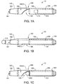
- FIGS. 1A-1C An exemplary recanalization system 10 is illustrated in FIGS. 1A-1C .
- the recanalization system 10 includes a redirecting delivery catheter 100 and a guidewire 200, although the recanalization system may include other types and numbers of devices, components, and/or other elements in other configurations, including, by way of example only, additional guidewires.
- two guidewires or other longitudinal members may be used in an antegrade/retrograde configuration where one of the longitudinal members is configured to serve as an antegrade member and another longitudinal member is configured to serve as a retrograde member.
- This exemplary technology provides a number of advantages including providing a system that allows for recanalization of chronic total occlusions. Additionally, the exemplary system advantageously allows for redirecting a guidewire inserted into a vessel to access the lumen from a lateral direction, while at the same time limiting the amount of lateral force applied in accessing the lumen.
- the redirecting delivery catheter 100 includes a distal end 102, a proximal end 104, an outer surface 106, an inner chamber 108, a first region 110, a second region 120, an opening 130, and a deflecting mechanism 150(1), although the redirecting delivery catheter may include other types and numbers of components, and/or other elements in other configurations.
- the redirecting delivery catheter 100 extends as a longitudinal member along a length between the distal end 102 and the proximal end 104 with the cylindrical outer surface 106, although outer surface 106 may have other shapes such as oval or flat (eccentric).
- the redirecting delivery catheter 100 may have any length known in the art for catheters.
- the cylindrical outer surface defines the cylindrical inner chamber 108 that is configured to accommodate a second longitudinal member, such as a guidewire, although the redirecting delivery catheter 100 may have other layers inside the outer surface 106 that form the inner chamber 108.
- the first region 110 and the second region 120 of the redirecting delivery catheter 100 are defined by the positioning of the opening 130, although the redirecting delivery catheter 100 may have other numbers of regions defined in other manners.
- the first region 110 extends between the proximal end 104 of the redirecting delivery catheter 100 and the opening 130
- the second region 120 extends between the distal end 102 of the redirecting delivery catheter 100 and the opening 130.
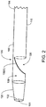
- the distal end 102 of the redirecting delivery catheter 100 has a tapered configuration with the diameter of a distal opening 161 configured to be smaller than the diameter of the second region 120 near the opening 130 of the redirecting delivery catheter 100, although the distal end 102 may have other configurations.
- first region 110 and/or the second region 120 has a helical exterior, although other configurations may be utilized.
- the first region 110 and the second region 120 may further comprise a plurality of wires that serve as conductive wires.
- the plurality of wires may have different diameters.
- the opening 130 extends along a portion of the outer surface 106 of the redirecting delivery catheter 100, such that the opening 130 is positioned in a direction lateral to the distal opening 161.
- the opening 130 may have various lengths along the outer surface 106 depending on the application. As shown in FIG. 2 , the opening 130 is configured as a flat opening in the outer surface 106.
- the deflecting mechanism 150(1) is located near the opening 130.
- the deflecting mechanism 150(1) is shown in FIG. 2 in its default position.
- the deflecting mechanism 150(1) provides a first position as shown, by way of example, in FIGS. 1A and 1C , and a second position as shown, by way of example in FIG. 1B .
- the first position which in this example is the default position of the deflecting mechanism 150(1)
- the deflecting mechanism 150(1) prevents access of a second longitudinal member, such as guidewire 200 inserted into the first region 110 along the inner chamber 108, to the second region 120 of the redirecting delivery catheter 100.
- the deflecting mechanism 150(1) has a substantially curved configuration in the first position, as shown in FIGS. 1A, 1C , and 2 , in order to direct the guidewire 200 in direction lateral to the distal opening 161 of the redirecting delivery catheter when the guidewire is pushed toward the deflecting mechanism 150(1), although other configurations may be utilized.
- the deflecting mechanism 150(1) may be a polymer tube capable of being compressed into the second position as shown in FIG. 1B . In the second position, by way of example, the deflecting mechanism 150(1) is compressed to allow access of the guidewire 200 to the second region 120 of the redirecting delivery catheter 100 and to the distal opening 161.
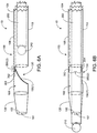
- FIGS. 3A and 3B Another example of a recanalization system 10 including the redirecting delivery catheter 100 and the guidewire 200, where the redirecting delivery catheter 100 includes a deflecting mechanism 150(2), is shown in FIGS. 3A and 3B .
- the deflecting mechanism 150(2) is defined by two lips 165 and 166 that meet to form a one-way valve, although other numbers of lips or other structures may be utilized.
- the deflecting mechanism 150(2) may be constructed, by way of example, of a flexible polymer, although other materials may be utilized.
- the deflecting mechanism 150(2) provides a first position, as shown in FIG. 3A , where the one-way valve prevents access of a second longitudinal member, such as guidewire 200 inserted into the first region 110 along the inner chamber 108, to the second region 120 of the redirecting delivery catheter 100.
- the deflecting mechanism 150(2) directs the guidewire 200 in direction lateral to the distal opening 161 of the redirecting delivery catheter when the guidewire is pushed toward the deflecting mechanism 150(2), although other configurations may be utilized.
- the second position as shown in FIG. 3B , each of the lips 165 and 166 of the deflecting mechanism 150(2) are compressed to allow access of the guidewire 200 to the second region 120 of the redirecting delivery catheter 100 and to the distal opening 161.
- the deflecting mechanism 150(2) effectively prevents the guidewire 200 from reentering into the second region 120.
- the deflecting mechanism comprises a membrane covering that can be penetrated by the guidewire, although said membrane is configured to create a resistance such that sufficient force must be applied to overcome the resistance in order to traverse the membrane.
- the redirecting delivery element or catheter may comprise additional or optional components.
- the redirecting delivery catheter 100 may comprise multiple radiopaque markers to help determine the orientation of the catheter relative to the lumen of the vessel.
- the redirecting delivery catheter 100 may have an orientation marker 260 placed at a location opposite the opening 130 that serves to orient the opening 130 towards the lumen and away from the vessel wall.
- the redirecting delivery catheter 100 may further include a second marker 261 that serves to allow for approximate location of the window.
- two markers 260 and 261 are shown in FIG. 4
- the redirecting delivery catheter 100 may include a single radiopaque marker in a single L-shaped configuration.
- the redirecting delivery catheter 100 further includes a support element 350(1) which is included to support the integrity to the deflecting mechanism 150(1), by way of example, in moving from a first position (with the opening 130 open) to a second position (with the opening 130 closed).
- the support element 350(1) is a circular ring that extends around the inner chamber 108 when the deflecting mechanism 150(1) is compressed to close the opening 130 as shown in FIG. 5A .
- the support member 350(1) is compressible to form a semicircular ring, as shown in FIGS. 5B and 5C , when the deflecting mechanism 150(1) is extended across the inner chamber 108 with the opening 130 unobstructed.
- the support element 350(1) may be constructed of a polymer or a shape memory material such as nitinol, although the support element 350(1) may be constructed of other biocompatible materials.
- the redirecting delivery catheter 100 includes a support element 350(2) for supporting the integrity of the deflecting mechanism 150(1) that includes a pair of magnets 352 and 354 with opposite polarity.
- the pair of magnets 352 and 354 may serve as the deflecting mechanism themselves.
- contact between the magnets 352 and 354 is prevented by the guidewire 200 as shown in FIG. 6B .
- the magnets 352 and 354 Upon retraction of the guidewire 200, the magnets 352 and 354 are no longer obstructed by the guidewire 200 and are able to make contact, thus compressing the deflecting mechanism 150(1) and transforming the deflecting mechanism 150(1) to a closed position with respect to the inner chamber 108 as shown in FIG. 6A .
- the recanalization system 10 further includes the guidewire 200 or other longitudinal member, and may optionally include additional guidewires or other longitudinal members.
- two guidewires or other longitudinal members may be used in an antegrade/retrograde configuration where one of the longitudinal members is configured to serve as an antegrade member and another longitudinal member is configured to serve as a retrograde member.
- the recanalization system 10 may include a second longitudinal member such as balloon catheter 600 with balloon 605 and a conductive electrode at either location 610 or location 620, as shown in FIG. 7 . While the term "guidewire” is used to refer to a longitudinal member, it is to be understood that the term “guidewire” as used herein is intended to include any other type of longitudinal member including catheters, microcatheters, or dilating catheters.
- the guidewire 200 includes a conductive electrode 210 located on a distal tip thereof, although the guidewire 200 may include any other number of conductive electrodes or other electrodes in other positions.
- an electrode may be located on the side of the distal tip which directs the RF energy away from the vessel wall, thereby minimizing potential RF injury to the vessel wall.
- An RF generator or controller may serve as a source of RF energy to be provided to the longitudinal members, such as guidewire 200.
- the RF generator may be a hand-held battery-operated device, although other types and numbers of RF generators may be utilized.
- the one or more longitudinal members, such as guidewire 200 of the recanalization system 10 comprise one or more ultrasound transducers, instead of or in addition to RF electrodes.
- the ultrasound transducers provide ultrasound energy for ablating an occlusion.
- the antegrade and/or the retrograde longitudinal members may comprise ultrasound transducers and ablate the lesion from an antegrade as well as a retrograde direction, although other energy modalities could be utilized such as microwave and laser.
- a pigtail connects at a proximal end 214 of the guidewire 200 to the RF generator and terminates at its distal end in a connector.
- the connector couples the input and output signals of the RF generator to the guidewire 200 and may take the form of a device similar to a torque device.
- the guidewire 200 is shown as positioned in the first region 110 of the redirecting delivery catheter 100.
- the guidewire 200 is shown to be housed within the redirecting delivery catheter 100.
- the guidewire 200 is shown to have traversed the length of the first region 110, the opening 130, and the second region 120.
- a portion of the guidewire 200 including the conductive electrode 210 is shown to have traversed the distal opening 161 such that it would be exposed to a tissue region when implemented in a lumen of a patient.
- the guidewire 200 is positioned such that the conductive electrode 210 is placed at the window 130.
- the deflecting mechanism 150(1) is compressed in a default state.
- the compressed configuration of the deflecting mechanism 150(1) creates a barrier that prevents the guidewire 200 from entering in to the second region 120, thus causing the guidewire 200 to be positioned at the opening 130.
- the sequence of the recanalization treatment steps includes advancing the guidewire 200 into a vessel of a patient in an antegrade direction.
- the guidewire 200 may be advanced into an occlusion or subintimal space using standard angioplasty techniques.
- the redirecting catheter 100 is then back loaded onto the guidewire 200 such that the guidewire is positioned as shown in FIG. 1B .
- Backloading the redirecting delivery catheter 100 onto the guidewire 200 causes the deflecting mechanism 150(1) to be compressed such that the guidewire 200 occupies the first region 110 and the second region 120 of the redirecting delivery catheter.
- the opening 130 of the redirecting delivery catheter is advanced to a position where the guidewire is to be redirected.
- the guidewire 200 is retracted within the redirecting delivery catheter 100 past the deflecting mechanism 150(1) and into the first region 110, effectively decompressing the deflecting mechanism 150(1) and clearing access to the opening 130.
- the guidewire 200 is then re-advanced toward the deflecting mechanism 150(1).
- the configuration of the deflecting mechanism which in this example includes a curved shape as shown in FIG. 1C , deflects the guidewire 200 laterally toward the opening 130 to provide contact with the occlusion or tissue located outside the opening 130.
- the deflecting mechanism 150(1) in this position which is the default position of the deflecting mechanism 150(1) effectively blocks access of the guidewire 200 to the first region
- a second guidewire or longitudinal member such as balloon catheter 600 as shown in FIG. 7 is then advanced retrogradely towards the distal end of the occlusion and serves as the second conductive electrode 610/620 to create a bipolar arrangement, although the balloon catheter could also serve as the antegrade electrode with a separate guidewire providing the retrograde electrode. Energy treatment is then initiated.
- the second conductive electrode is also advanced in the antegrade direction into the occlusion or subintimal space.
- the second conductive electrode may be located on the balloon catheter 600.
- the balloon catheter 600 includes a second conductive electrode 610/620 that may be inside the balloon 605 (610) or outside the balloon 605 (620).
- the first conductive electrode 210 is positioned in the subintimal space while the second conductive electrode 610/620 is located inside the balloon 605 (610) or within the blood vessel (620), respectively, or both.
- the second electrode 610 has the added benefit of centering the second electrode within the lumen thus facilitating the positioning of the electrically active regions with respect to the first electrode 210.
- the resulting spark will cause the balloon 605 to rupture.
- This observable event visible or audible, can act as a confirmation trigger letting the operator know that an electrical connection and likely a channel has been formed between the electrodes.
- the guidewires are advanced as deep into the occlusion as possible to minimize the distance between the electrodes and, consequently, minimize the length of the ablation zone. Confirmation that the guidewires are in an appropriate position can be generated by impedance measurements and/or by using any of the standard imaging techniques employed during interventional procedures, such as fluoroscopy or intravascular ultrasound (IVUS), in which transducers are placed on the distal ends of the guidewires.
- IVUS intravascular ultrasound
- the present technology may be utilized to combine the use of energy delivered through antegrade and retrograde members for recanalizing occluded lumens, particularly chronic total occlusions.
- the methods and systems described herein recanalize difficult to cross occlusions by taking advantage of an antegrade and retrograde approach to establish a bipolar electrode arrangement across the occlusion. This approach minimizes the potential of the vessel wall becoming perforated or injured, as may otherwise occur in a conventional bipolar RF treatment approach, where both RF electrodes are on the same side of the occlusion. Because the electrodes are distributed on opposite sides of the occlusion, the tissue that is ablated by the RF treatment (i.e., the occlusion) is well contained between the electrodes. This also allows the user to localize the treatment to the occlusion.
- the retrograde approach takes advantage of an intercoronary channel.
- a channel may be an epicardial channel, an inter-atrial channel, an intra-septal channel (also referred to as septal collateral), or a bypass graft.
- the basic concept of the CART technique is to create a channel through an occlusion, preferably with limited dissections, by approaching the occlusion both in the antegrade and retrograde directions.
- Electrodes can also be referred to as the return and active electrodes. They are also referred to as the anode and cathode, respectively.
- the electrodes could also be arranged in an array (multiple electrodes), where the electrode arrangement provides better control over the depth of penetration of the RF field and thereby provides the ability to control the tissue temperature.
- the combined antegrade and retrograde energy delivery techniques described above could also be used as an adjunct technique to crossing CTOs in combination with using conventional methods.
- the technique could be used to sufficiently soften or weaken the occlusion, thereby allowing a guidewire or catheter to cross the occlusion.
- the redirecting delivery element 100 or catheter can also be used without the use of energy.
- the redirecting delivery catheter 100 can be used to redirect a subsequent guidewire by deflecting the guidewire towards the lumen and away from the vessel wall.
- the subsequent guidewire comprises a sharp tip.
- the subsequent guidewire takes the form of a 3-dimensional distal tip. In this configuration, the 3-dimensional guidewire can be rotated rather than axially advanced to access the vessel lumen. This serves to reduce the lateral force placed on the subintimal space when a guidewire is advanced axially which can often lead to enlargement of the subintimal space. It should be noted that the use of energy similarly reduces the lateral force placed on the subintimal space.
- the redirecting delivery element 100 or catheter can be used for treating bifurcations.
- the redirecting catheter 100 is advanced over the guidewire 200 into the main vessel until the opening 130 is located near the side branch.
- the guidewire 200 can be retracted until the deflecting mechanism 150(1) is activated and then the guidewire 200 is advanced through the opening 130 into the side branch.
Landscapes
- Health & Medical Sciences (AREA)
- Life Sciences & Earth Sciences (AREA)
- Engineering & Computer Science (AREA)
- Veterinary Medicine (AREA)
- General Health & Medical Sciences (AREA)
- Biomedical Technology (AREA)
- Heart & Thoracic Surgery (AREA)
- Public Health (AREA)
- Animal Behavior & Ethology (AREA)
- Surgery (AREA)
- Pulmonology (AREA)
- Biophysics (AREA)
- Anesthesiology (AREA)
- Hematology (AREA)
- Molecular Biology (AREA)
- Medical Informatics (AREA)
- Nuclear Medicine, Radiotherapy & Molecular Imaging (AREA)
- Otolaryngology (AREA)
- Plasma & Fusion (AREA)
- Physics & Mathematics (AREA)
- Cardiology (AREA)
- Vascular Medicine (AREA)
- Media Introduction/Drainage Providing Device (AREA)
- Surgical Instruments (AREA)
Applications Claiming Priority (2)
| Application Number | Priority Date | Filing Date | Title |
|---|---|---|---|
| US201462066311P | 2014-10-20 | 2014-10-20 | |
| PCT/IB2015/002386 WO2016063138A2 (en) | 2014-10-20 | 2015-12-18 | Redirecting delivery catheter and methods of use thereof |
Publications (3)
| Publication Number | Publication Date |
|---|---|
| EP3209362A2 EP3209362A2 (en) | 2017-08-30 |
| EP3209362A4 EP3209362A4 (en) | 2018-04-18 |
| EP3209362B1 true EP3209362B1 (en) | 2020-04-15 |
Family
ID=55748102
Family Applications (1)
| Application Number | Title | Priority Date | Filing Date |
|---|---|---|---|
| EP15851891.0A Active EP3209362B1 (en) | 2014-10-20 | 2015-12-18 | Redirecting delivery catheter |
Country Status (4)
| Country | Link |
|---|---|
| US (1) | US10383683B2 (ko) |
| EP (1) | EP3209362B1 (ko) |
| JP (1) | JP6887949B2 (ko) |
| WO (1) | WO2016063138A2 (ko) |
Families Citing this family (16)
| Publication number | Priority date | Publication date | Assignee | Title |
|---|---|---|---|---|
| US10376308B2 (en) | 2015-02-05 | 2019-08-13 | Axon Therapies, Inc. | Devices and methods for treatment of heart failure by splanchnic nerve ablation |
| EP3490442A4 (en) | 2016-07-29 | 2020-03-25 | Axon Therapies, Inc. | DEVICES, SYSTEMS AND METHODS FOR THE TREATMENT OF HEART FAILURE BY ABLATION OF SPLANCHNIC NERVE |
| US11400205B2 (en) | 2016-11-23 | 2022-08-02 | Biosense Webster (Israel) Ltd. | Balloon-in-balloon irrigation balloon catheter |
| US10561461B2 (en) | 2017-12-17 | 2020-02-18 | Axon Therapies, Inc. | Methods and devices for endovascular ablation of a splanchnic nerve |
| WO2019148094A1 (en) | 2018-01-26 | 2019-08-01 | Axon Therapies, Inc. | Methods and devices for endovascular ablation of a splanchnic nerve |
| CN109045439B (zh) * | 2018-08-21 | 2020-08-14 | 业聚医疗器械(深圳)有限公司 | 一种导管系统 |
| US11654271B2 (en) * | 2019-04-04 | 2023-05-23 | PHVC Scientific LLC | Vascular access with retrograde and antegrade delivery modes |
| USD969138S1 (en) | 2019-05-31 | 2022-11-08 | Biosense Webster (Israel) Ltd. | Display screen with a graphical user interface |
| USD968422S1 (en) | 2019-05-31 | 2022-11-01 | Biosense Webster (Israel) Ltd. | Display screen with transitional graphical user interface |
| USD968421S1 (en) | 2019-05-31 | 2022-11-01 | Biosense Webster (Israel) Ltd. | Display screen with a graphical user interface |
| AU2020296866A1 (en) | 2019-06-20 | 2021-10-14 | Axon Therapies, Inc. | Methods and devices for endovascular ablation of a splanchnic nerve |
| JP2023510597A (ja) | 2020-01-17 | 2023-03-14 | アクソン セラピーズ,インク. | 内臓神経の血管内アブレーションの方法及びデバイス |
| EP4217039A1 (en) * | 2020-09-25 | 2023-08-02 | Boston Scientific Medical Device Limited | Elongated catheter assembly having guidewire deflector |
| US11974803B2 (en) | 2020-10-12 | 2024-05-07 | Biosense Webster (Israel) Ltd. | Basket catheter with balloon |
| US11957852B2 (en) | 2021-01-14 | 2024-04-16 | Biosense Webster (Israel) Ltd. | Intravascular balloon with slidable central irrigation tube |
| WO2023218467A1 (en) * | 2022-05-13 | 2023-11-16 | Strauss Bradley Howard | Bendable guidewire lumen |
Family Cites Families (26)
| Publication number | Priority date | Publication date | Assignee | Title |
|---|---|---|---|---|
| US4552554A (en) | 1984-06-25 | 1985-11-12 | Medi-Tech Incorporated | Introducing catheter |
| JPS63262160A (ja) * | 1987-04-20 | 1988-10-28 | テルモ株式会社 | カテ−テル |
| US5419767A (en) | 1992-01-07 | 1995-05-30 | Thapliyal And Eggers Partners | Methods and apparatus for advancing catheters through severely occluded body lumens |
| US5366443A (en) | 1992-01-07 | 1994-11-22 | Thapliyal And Eggers Partners | Method and apparatus for advancing catheters through occluded body lumens |
| ATE182273T1 (de) | 1992-08-18 | 1999-08-15 | Spectranetics Corp | Führungsdraht mit faseroptik |
| AU730720C (en) * | 1996-11-08 | 2001-11-08 | Thomas J. Fogarty | Transvascular TMR device and method |
| US6183432B1 (en) | 1997-11-13 | 2001-02-06 | Lumend, Inc. | Guidewire and catheter with rotating and reciprocating symmetrical or asymmetrical distal tip |
| US6217527B1 (en) * | 1998-09-30 | 2001-04-17 | Lumend, Inc. | Methods and apparatus for crossing vascular occlusions |
| US6911026B1 (en) | 1999-07-12 | 2005-06-28 | Stereotaxis, Inc. | Magnetically guided atherectomy |
| AU2628801A (en) | 2000-01-04 | 2001-07-16 | Transvascular, Inc. | Apparatus for creating a channel between adjacent body lumens |
| SE523427C2 (sv) * | 2000-03-20 | 2004-04-20 | Jan Otto Solem | Katetersystem för förbikoppling av en artärblockering |
| US6416523B1 (en) | 2000-10-03 | 2002-07-09 | Scimed Life Systems, Inc. | Method and apparatus for creating channels through vascular total occlusions |
| US20030032936A1 (en) | 2001-08-10 | 2003-02-13 | Lederman Robert J. | Side-exit catheter and method for its use |
| US7081113B2 (en) | 2003-06-26 | 2006-07-25 | Depuy Acromed, Inc. | Helical probe |
| US7402141B2 (en) | 2003-08-27 | 2008-07-22 | Heuser Richard R | Catheter guidewire system using concentric wires |
| US8545418B2 (en) * | 2004-08-25 | 2013-10-01 | Richard R. Heuser | Systems and methods for ablation of occlusions within blood vessels |
| US20060047335A1 (en) | 2004-08-26 | 2006-03-02 | Israel Henry M | Catheter with deflector |
| US7815601B2 (en) * | 2007-02-05 | 2010-10-19 | Boston Scientific Scimed, Inc. | Rapid exchange enteral stent delivery system |
| US20100191151A1 (en) * | 2007-06-15 | 2010-07-29 | Taewoong Medical Co., Ltd. | Bipolar electrode type guide wire and catheter system |
| US20090247933A1 (en) * | 2008-03-27 | 2009-10-01 | The Regents Of The University Of California; Angiodynamics, Inc. | Balloon catheter method for reducing restenosis via irreversible electroporation |
| US8874237B2 (en) * | 2008-04-16 | 2014-10-28 | Medtronic, Inc. | Delivery catheter including side port and electrodes |
| WO2009143077A1 (en) * | 2008-05-17 | 2009-11-26 | Spirus Medical, Inc. | Rotate-to-advance catheterization system |
| ES2671898T3 (es) * | 2008-06-13 | 2018-06-11 | Shockwave Medical, Inc. | Sistema de catéter con globo de ondas de choque |
| US8998936B2 (en) | 2011-06-30 | 2015-04-07 | The Spectranetics Corporation | Reentry catheter and method thereof |
| US20140074108A1 (en) | 2012-09-10 | 2014-03-13 | Cook Medical Technologies Llc | Reentry device |
| US9220913B2 (en) * | 2013-05-06 | 2015-12-29 | Medtronics, Inc. | Multi-mode implantable medical device |
-
2015
- 2015-10-20 US US14/887,940 patent/US10383683B2/en active Active
- 2015-12-18 JP JP2017540333A patent/JP6887949B2/ja active Active
- 2015-12-18 EP EP15851891.0A patent/EP3209362B1/en active Active
- 2015-12-18 WO PCT/IB2015/002386 patent/WO2016063138A2/en active Application Filing
Non-Patent Citations (1)
| Title |
|---|
| None * |
Also Published As
| Publication number | Publication date |
|---|---|
| US20160106499A1 (en) | 2016-04-21 |
| US10383683B2 (en) | 2019-08-20 |
| EP3209362A4 (en) | 2018-04-18 |
| EP3209362A2 (en) | 2017-08-30 |
| WO2016063138A3 (en) | 2016-06-30 |
| WO2016063138A2 (en) | 2016-04-28 |
| JP2017531544A (ja) | 2017-10-26 |
| JP6887949B2 (ja) | 2021-06-16 |
Similar Documents
| Publication | Publication Date | Title |
|---|---|---|
| EP3209362B1 (en) | Redirecting delivery catheter | |
| US20200078088A1 (en) | Recanalizing occluded vessels using radiofrequency energy | |
| JP6785832B2 (ja) | 高周波エネルギを用いた閉塞血管再疎通術 | |
| US10779884B2 (en) | Energy facilitated composition delivery | |
| AU2011235882A1 (en) | Recanalizing occluded vessels using radiofrequency energy |
Legal Events
| Date | Code | Title | Description |
|---|---|---|---|
| STAA | Information on the status of an ep patent application or granted ep patent |
Free format text: STATUS: THE INTERNATIONAL PUBLICATION HAS BEEN MADE |
|
| PUAI | Public reference made under article 153(3) epc to a published international application that has entered the european phase |
Free format text: ORIGINAL CODE: 0009012 |
|
| STAA | Information on the status of an ep patent application or granted ep patent |
Free format text: STATUS: REQUEST FOR EXAMINATION WAS MADE |
|
| 17P | Request for examination filed |
Effective date: 20170419 |
|
| AK | Designated contracting states |
Kind code of ref document: A2 Designated state(s): AL AT BE BG CH CY CZ DE DK EE ES FI FR GB GR HR HU IE IS IT LI LT LU LV MC MK MT NL NO PL PT RO RS SE SI SK SM TR |
|
| AX | Request for extension of the european patent |
Extension state: BA ME |
|
| RIN1 | Information on inventor provided before grant (corrected) |
Inventor name: OGATA, WAYNE Inventor name: GU, XIANG IAN Inventor name: MEYER, STEVEN |
|
| DAV | Request for validation of the european patent (deleted) | ||
| DAX | Request for extension of the european patent (deleted) | ||
| A4 | Supplementary search report drawn up and despatched |
Effective date: 20180316 |
|
| RIC1 | Information provided on ipc code assigned before grant |
Ipc: A61B 18/14 20060101ALI20180312BHEP Ipc: A61B 17/3207 20060101ALI20180312BHEP Ipc: A61M 25/09 20060101ALI20180312BHEP Ipc: A61M 25/01 20060101AFI20180312BHEP |
|
| STAA | Information on the status of an ep patent application or granted ep patent |
Free format text: STATUS: EXAMINATION IS IN PROGRESS |
|
| 17Q | First examination report despatched |
Effective date: 20181109 |
|
| GRAP | Despatch of communication of intention to grant a patent |
Free format text: ORIGINAL CODE: EPIDOSNIGR1 |
|
| STAA | Information on the status of an ep patent application or granted ep patent |
Free format text: STATUS: GRANT OF PATENT IS INTENDED |
|
| INTG | Intention to grant announced |
Effective date: 20190705 |
|
| GRAS | Grant fee paid |
Free format text: ORIGINAL CODE: EPIDOSNIGR3 |
|
| GRAJ | Information related to disapproval of communication of intention to grant by the applicant or resumption of examination proceedings by the epo deleted |
Free format text: ORIGINAL CODE: EPIDOSDIGR1 |
|
| GRAL | Information related to payment of fee for publishing/printing deleted |
Free format text: ORIGINAL CODE: EPIDOSDIGR3 |
|
| STAA | Information on the status of an ep patent application or granted ep patent |
Free format text: STATUS: EXAMINATION IS IN PROGRESS |
|
| GRAP | Despatch of communication of intention to grant a patent |
Free format text: ORIGINAL CODE: EPIDOSNIGR1 |
|
| STAA | Information on the status of an ep patent application or granted ep patent |
Free format text: STATUS: GRANT OF PATENT IS INTENDED |
|
| INTC | Intention to grant announced (deleted) | ||
| INTG | Intention to grant announced |
Effective date: 20191202 |
|
| GRAA | (expected) grant |
Free format text: ORIGINAL CODE: 0009210 |
|
| STAA | Information on the status of an ep patent application or granted ep patent |
Free format text: STATUS: THE PATENT HAS BEEN GRANTED |
|
| AK | Designated contracting states |
Kind code of ref document: B1 Designated state(s): AL AT BE BG CH CY CZ DE DK EE ES FI FR GB GR HR HU IE IS IT LI LT LU LV MC MK MT NL NO PL PT RO RS SE SI SK SM TR |
|
| REG | Reference to a national code |
Ref country code: CH Ref legal event code: EP |
|
| REG | Reference to a national code |
Ref country code: DE Ref legal event code: R096 Ref document number: 602015050889 Country of ref document: DE |
|
| REG | Reference to a national code |
Ref country code: IE Ref legal event code: FG4D |
|
| REG | Reference to a national code |
Ref country code: AT Ref legal event code: REF Ref document number: 1256530 Country of ref document: AT Kind code of ref document: T Effective date: 20200515 |
|
| REG | Reference to a national code |
Ref country code: NL Ref legal event code: MP Effective date: 20200415 |
|
| REG | Reference to a national code |
Ref country code: LT Ref legal event code: MG4D |
|
| PG25 | Lapsed in a contracting state [announced via postgrant information from national office to epo] |
Ref country code: NO Free format text: LAPSE BECAUSE OF FAILURE TO SUBMIT A TRANSLATION OF THE DESCRIPTION OR TO PAY THE FEE WITHIN THE PRESCRIBED TIME-LIMIT Effective date: 20200715 Ref country code: IS Free format text: LAPSE BECAUSE OF FAILURE TO SUBMIT A TRANSLATION OF THE DESCRIPTION OR TO PAY THE FEE WITHIN THE PRESCRIBED TIME-LIMIT Effective date: 20200815 Ref country code: PT Free format text: LAPSE BECAUSE OF FAILURE TO SUBMIT A TRANSLATION OF THE DESCRIPTION OR TO PAY THE FEE WITHIN THE PRESCRIBED TIME-LIMIT Effective date: 20200817 Ref country code: FI Free format text: LAPSE BECAUSE OF FAILURE TO SUBMIT A TRANSLATION OF THE DESCRIPTION OR TO PAY THE FEE WITHIN THE PRESCRIBED TIME-LIMIT Effective date: 20200415 Ref country code: GR Free format text: LAPSE BECAUSE OF FAILURE TO SUBMIT A TRANSLATION OF THE DESCRIPTION OR TO PAY THE FEE WITHIN THE PRESCRIBED TIME-LIMIT Effective date: 20200716 Ref country code: NL Free format text: LAPSE BECAUSE OF FAILURE TO SUBMIT A TRANSLATION OF THE DESCRIPTION OR TO PAY THE FEE WITHIN THE PRESCRIBED TIME-LIMIT Effective date: 20200415 Ref country code: LT Free format text: LAPSE BECAUSE OF FAILURE TO SUBMIT A TRANSLATION OF THE DESCRIPTION OR TO PAY THE FEE WITHIN THE PRESCRIBED TIME-LIMIT Effective date: 20200415 Ref country code: SE Free format text: LAPSE BECAUSE OF FAILURE TO SUBMIT A TRANSLATION OF THE DESCRIPTION OR TO PAY THE FEE WITHIN THE PRESCRIBED TIME-LIMIT Effective date: 20200415 |
|
| REG | Reference to a national code |
Ref country code: AT Ref legal event code: MK05 Ref document number: 1256530 Country of ref document: AT Kind code of ref document: T Effective date: 20200415 |
|
| PG25 | Lapsed in a contracting state [announced via postgrant information from national office to epo] |
Ref country code: RS Free format text: LAPSE BECAUSE OF FAILURE TO SUBMIT A TRANSLATION OF THE DESCRIPTION OR TO PAY THE FEE WITHIN THE PRESCRIBED TIME-LIMIT Effective date: 20200415 Ref country code: BG Free format text: LAPSE BECAUSE OF FAILURE TO SUBMIT A TRANSLATION OF THE DESCRIPTION OR TO PAY THE FEE WITHIN THE PRESCRIBED TIME-LIMIT Effective date: 20200715 Ref country code: HR Free format text: LAPSE BECAUSE OF FAILURE TO SUBMIT A TRANSLATION OF THE DESCRIPTION OR TO PAY THE FEE WITHIN THE PRESCRIBED TIME-LIMIT Effective date: 20200415 Ref country code: LV Free format text: LAPSE BECAUSE OF FAILURE TO SUBMIT A TRANSLATION OF THE DESCRIPTION OR TO PAY THE FEE WITHIN THE PRESCRIBED TIME-LIMIT Effective date: 20200415 |
|
| PG25 | Lapsed in a contracting state [announced via postgrant information from national office to epo] |
Ref country code: AL Free format text: LAPSE BECAUSE OF FAILURE TO SUBMIT A TRANSLATION OF THE DESCRIPTION OR TO PAY THE FEE WITHIN THE PRESCRIBED TIME-LIMIT Effective date: 20200415 |
|
| REG | Reference to a national code |
Ref country code: DE Ref legal event code: R097 Ref document number: 602015050889 Country of ref document: DE |
|
| PG25 | Lapsed in a contracting state [announced via postgrant information from national office to epo] |
Ref country code: DK Free format text: LAPSE BECAUSE OF FAILURE TO SUBMIT A TRANSLATION OF THE DESCRIPTION OR TO PAY THE FEE WITHIN THE PRESCRIBED TIME-LIMIT Effective date: 20200415 Ref country code: SM Free format text: LAPSE BECAUSE OF FAILURE TO SUBMIT A TRANSLATION OF THE DESCRIPTION OR TO PAY THE FEE WITHIN THE PRESCRIBED TIME-LIMIT Effective date: 20200415 Ref country code: AT Free format text: LAPSE BECAUSE OF FAILURE TO SUBMIT A TRANSLATION OF THE DESCRIPTION OR TO PAY THE FEE WITHIN THE PRESCRIBED TIME-LIMIT Effective date: 20200415 Ref country code: IT Free format text: LAPSE BECAUSE OF FAILURE TO SUBMIT A TRANSLATION OF THE DESCRIPTION OR TO PAY THE FEE WITHIN THE PRESCRIBED TIME-LIMIT Effective date: 20200415 Ref country code: EE Free format text: LAPSE BECAUSE OF FAILURE TO SUBMIT A TRANSLATION OF THE DESCRIPTION OR TO PAY THE FEE WITHIN THE PRESCRIBED TIME-LIMIT Effective date: 20200415 Ref country code: ES Free format text: LAPSE BECAUSE OF FAILURE TO SUBMIT A TRANSLATION OF THE DESCRIPTION OR TO PAY THE FEE WITHIN THE PRESCRIBED TIME-LIMIT Effective date: 20200415 Ref country code: CZ Free format text: LAPSE BECAUSE OF FAILURE TO SUBMIT A TRANSLATION OF THE DESCRIPTION OR TO PAY THE FEE WITHIN THE PRESCRIBED TIME-LIMIT Effective date: 20200415 Ref country code: RO Free format text: LAPSE BECAUSE OF FAILURE TO SUBMIT A TRANSLATION OF THE DESCRIPTION OR TO PAY THE FEE WITHIN THE PRESCRIBED TIME-LIMIT Effective date: 20200415 |
|
| PLBE | No opposition filed within time limit |
Free format text: ORIGINAL CODE: 0009261 |
|
| STAA | Information on the status of an ep patent application or granted ep patent |
Free format text: STATUS: NO OPPOSITION FILED WITHIN TIME LIMIT |
|
| PG25 | Lapsed in a contracting state [announced via postgrant information from national office to epo] |
Ref country code: PL Free format text: LAPSE BECAUSE OF FAILURE TO SUBMIT A TRANSLATION OF THE DESCRIPTION OR TO PAY THE FEE WITHIN THE PRESCRIBED TIME-LIMIT Effective date: 20200415 Ref country code: SK Free format text: LAPSE BECAUSE OF FAILURE TO SUBMIT A TRANSLATION OF THE DESCRIPTION OR TO PAY THE FEE WITHIN THE PRESCRIBED TIME-LIMIT Effective date: 20200415 |
|
| 26N | No opposition filed |
Effective date: 20210118 |
|
| PG25 | Lapsed in a contracting state [announced via postgrant information from national office to epo] |
Ref country code: SI Free format text: LAPSE BECAUSE OF FAILURE TO SUBMIT A TRANSLATION OF THE DESCRIPTION OR TO PAY THE FEE WITHIN THE PRESCRIBED TIME-LIMIT Effective date: 20200415 |
|
| REG | Reference to a national code |
Ref country code: CH Ref legal event code: PL |
|
| PG25 | Lapsed in a contracting state [announced via postgrant information from national office to epo] |
Ref country code: MC Free format text: LAPSE BECAUSE OF FAILURE TO SUBMIT A TRANSLATION OF THE DESCRIPTION OR TO PAY THE FEE WITHIN THE PRESCRIBED TIME-LIMIT Effective date: 20200415 |
|
| REG | Reference to a national code |
Ref country code: BE Ref legal event code: MM Effective date: 20201231 |
|
| PG25 | Lapsed in a contracting state [announced via postgrant information from national office to epo] |
Ref country code: IE Free format text: LAPSE BECAUSE OF NON-PAYMENT OF DUE FEES Effective date: 20201218 Ref country code: LU Free format text: LAPSE BECAUSE OF NON-PAYMENT OF DUE FEES Effective date: 20201218 |
|
| PG25 | Lapsed in a contracting state [announced via postgrant information from national office to epo] |
Ref country code: LI Free format text: LAPSE BECAUSE OF NON-PAYMENT OF DUE FEES Effective date: 20201231 Ref country code: CH Free format text: LAPSE BECAUSE OF NON-PAYMENT OF DUE FEES Effective date: 20201231 |
|
| PG25 | Lapsed in a contracting state [announced via postgrant information from national office to epo] |
Ref country code: TR Free format text: LAPSE BECAUSE OF FAILURE TO SUBMIT A TRANSLATION OF THE DESCRIPTION OR TO PAY THE FEE WITHIN THE PRESCRIBED TIME-LIMIT Effective date: 20200415 Ref country code: MT Free format text: LAPSE BECAUSE OF FAILURE TO SUBMIT A TRANSLATION OF THE DESCRIPTION OR TO PAY THE FEE WITHIN THE PRESCRIBED TIME-LIMIT Effective date: 20200415 Ref country code: CY Free format text: LAPSE BECAUSE OF FAILURE TO SUBMIT A TRANSLATION OF THE DESCRIPTION OR TO PAY THE FEE WITHIN THE PRESCRIBED TIME-LIMIT Effective date: 20200415 |
|
| PG25 | Lapsed in a contracting state [announced via postgrant information from national office to epo] |
Ref country code: MK Free format text: LAPSE BECAUSE OF FAILURE TO SUBMIT A TRANSLATION OF THE DESCRIPTION OR TO PAY THE FEE WITHIN THE PRESCRIBED TIME-LIMIT Effective date: 20200415 |
|
| PG25 | Lapsed in a contracting state [announced via postgrant information from national office to epo] |
Ref country code: BE Free format text: LAPSE BECAUSE OF NON-PAYMENT OF DUE FEES Effective date: 20201231 |
|
| P01 | Opt-out of the competence of the unified patent court (upc) registered |
Effective date: 20230530 |
|
| PGFP | Annual fee paid to national office [announced via postgrant information from national office to epo] |
Ref country code: GB Payment date: 20231215 Year of fee payment: 9 |
|
| PGFP | Annual fee paid to national office [announced via postgrant information from national office to epo] |
Ref country code: FR Payment date: 20231229 Year of fee payment: 9 |
|
| PGFP | Annual fee paid to national office [announced via postgrant information from national office to epo] |
Ref country code: DE Payment date: 20231221 Year of fee payment: 9 |