EP3209119B1 - Verriegelung eines rotierenden kauspielzeugs - Google Patents
Verriegelung eines rotierenden kauspielzeugs Download PDFInfo
- Publication number
- EP3209119B1 EP3209119B1 EP15853206.9A EP15853206A EP3209119B1 EP 3209119 B1 EP3209119 B1 EP 3209119B1 EP 15853206 A EP15853206 A EP 15853206A EP 3209119 B1 EP3209119 B1 EP 3209119B1
- Authority
- EP
- European Patent Office
- Prior art keywords
- elongated half
- elongated
- detent
- locking pin
- locking
- Prior art date
- Legal status (The legal status is an assumption and is not a legal conclusion. Google has not performed a legal analysis and makes no representation as to the accuracy of the status listed.)
- Active
Links
Images


Classifications
-
- A—HUMAN NECESSITIES
- A01—AGRICULTURE; FORESTRY; ANIMAL HUSBANDRY; HUNTING; TRAPPING; FISHING
- A01K—ANIMAL HUSBANDRY; AVICULTURE; APICULTURE; PISCICULTURE; FISHING; REARING OR BREEDING ANIMALS, NOT OTHERWISE PROVIDED FOR; NEW BREEDS OF ANIMALS
- A01K15/00—Devices for taming animals, e.g. nose-rings or hobbles; Devices for overturning animals in general; Training or exercising equipment; Covering boxes
- A01K15/02—Training or exercising equipment, e.g. mazes or labyrinths for animals ; Electric shock devices; Toys specially adapted for animals
- A01K15/025—Toys specially adapted for animals
- A01K15/026—Chewable toys, e.g. for dental care of pets
Definitions
- the present disclosure is directed to a pet chew and, in particular, to a pet chew that includes halves rotatable relative to each other and a locking feature for stopping rotation of the halves.
- Pet chews are commonly used to help satiate an animal's desire for chewing. Dogs, in particular, are driven to chew on objects for a variety of reasons. In addition to alleviating teething discomfort, dogs may chew to gamer attention, alleviate boredom, redirect stress, or alleviate dietary imbalances. Chewing may also help to keep teeth clean.
- a number of pet chews have been developed to receive and retain edible treats.
- the edible treats may retain the pet's interest in the chew, supplement the pet's diet, or may be used as a part of a reward system for the pet.
- the edible treats such as biscuits or peanut butter, may be lodged within openings provided in the pet chew and may often extend out of the openings.
- the chew is molded as a hollow body. Treats may be inserted into the hollow cavity of the chew. The pet may try to dislodge the treats or lick the peanut butter out of the chew.
- one or more cavities or pockets are provided in the pet chew, wherein the cavity openings are smaller in cross-section than the cavities. The treats may be lodged in or inserted through the openings.
- CN 202979873 U discloses a food leaking ball which can serve as a pet toy and be used for feeding a pet.
- the food leaking ball comprises a ball bladder and a food leaking hole, and is characterized in that the ball bladder is formed by connecting a pin-type half ball with a slot-type half ball through a connecting pin; a foodstuff circulator is arranged in the ball bladder; and the food leaking hole is formed at a junction between the pin-type half ball and the slot-type half ball.
- US 2006/048718 A1 discloses a non-consumable pet toy including a resilient first concave-shaped molded member having a first peripheral edge and a resilient second concave-shaped molded member having a second peripheral edge, wherein The first and second members have a treat-retaining cavity between them.
- the treat retaining pet toy also includes a fastener extending centrally through the treat-retaining cavity, wherein the fastener fastens the first member to the second member such that the first peripheral edge is at a predetermined distance from the second peripheral edge.
- US 6,073,581 A discloses a ball-like dog toy includes a spherical shell and a cylindrical valve, the spherical shell being formed of two symmetrical half shells, the half shells having ribs and partition boards, the cylindrical valve being mounted in a hole on the spherical shell and retained between the ribs and partition boards of the half shells and rotated within a limited angle, wherein dog food is discharged out of the spherical shell through the cylindrical valve when the spherical shell is rolled on the ground; discharging of dog food is stopped when the dog stops from playing with the dog toy.
- US 2009/217885 A1 discloses a pet treat holder comprising two halves positively retaining a pet chew by means of mechanical clamping during use, wherein a threaded coupling pin arranged on one half is received in a corresponding threaded coupling hole arranged in the other half of the pet treat holder.
- An animal chew according to the invention comprises the features of independent claim 1. Preferred embodiments are set out in the dependent claims.
- the animal chew includes a first elongated half and a second elongated half rotatably secured to the first elongated half, wherein the halves are rotatable around an axis of rotation.
- the animal chew also includes a locking pin retained between the first elongated half and the second elongated half, wherein the locking pin slides up and down the axis of rotation into a locked position and an unlocked position.
- the animal chew further includes a chamber having an opening and an interior volume, wherein the chamber is formed in at least one of the first elongated half and the second elongated half. When the locking pin is in the locked position, rotation of the first elongated half relative to the second elongated half is impeded.
- An unclaimed aspect of the present disclosure relates to a method of operating a pet chew.
- the method may include providing a pet chew including a first elongated half and a second elongated half rotatably secured to the first elongated half wherein the halves are rotatable around an axis of rotation, a locking pin retained between the first elongated half and the second elongated half, and a chamber having an opening and an interior volume, wherein the chamber is defined in at least one of the first elongated half and the second elongated half.
- the method may further include inserting a treat at least partially into the chamber, rotating the first elongated half relative to the second elongated half such that the interior volume of the chamber is enclosed by the first elongated half and the second elongated half except for at the opening.
- the locking pin may be positioned in a locked position, impeding rotation of the first elongated half relative to the second elongated half.
- the invention is also directed to a method of assembling an animal chew toy according to independent claim 10.
- the present disclosure relates to a pet chew and, in particular, to a pet chew that includes two halves, rotatable relative to each other, and a locking feature to impede rotation.
- the chew also includes a chamber have an interior volume for securing a treat, at least partially within.
- the treat may be an edible treat such as a biscuit, peanut butter, or another pet chew exhibiting different characteristics.
- the interior volume may be exposed upon rotating the two halves, allowing the interior volume to be cleaned out and new treat to be inserted into the interior volume.
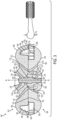
- FIGS. 1 , 2 and 3 illustrate an exemplary embodiment of a pet chew herein.
- the pet chew 100 includes two elongated halves, a first elongated half 102 and a second elongate half 104.
- the two elongated halves may assume the general shape of a dog bone having two arms 106, 108 each including a bulbous end.
- the arms extend from a center hub 110.
- Other alternative geometries may be assumed as well. For example, three, four, five, or six arms may be present extending from a center hub. In another example, a single or multiple arms arm joining at an end may be present extending from a hub positioned at the end of the arms.
- the two elongated halves may be formed of a polymer material, such as, acrylonitrile butadiene styrene (ABS), high impact polystyrene (HIPS), polypropylene (PP), high density polyethylene (HDPE), nylon or polyurethane.
- the polymer material may be a thermoplastic or a thermoset material.
- additives, such as colorants, flavorants, or attractants may be incorporated into the polymer material used to make the mold halves.
- Each elongated half may be formed from the same of different polymer materials.
- the elongated halves may be formed with different colorants, flavorants or attractants.
- the halves may be formed by a molding process, such as injection molding or compression molding, wherein the polymer material is caused to flow and fill a cavity to shape the elongated half.
- the two elongated halves 102, 104 are secured together in a rotatable manner. As illustrated, the two elongated halves are secured together in the center of the elongated halves, at the hub 110. As alluded to above, in other embodiments, the elongated halves may be secured together at a hub located at either end of the elongated halves or between the center and either end of the elongated halves.
- a flange 112 extending from one elongated half is received in a channel 114 formed in the other elongated half, which prevents the two halves 102, 104 from being separated but allows the two halves to rotate relative to each other around an axis of rotation A-A.
- the flange 112 may extend from a surface 116 of the first elongated half 102.
- the flange 112 may be arcuate.
- the flange 112 may be circular, wherein the circle formed by the flange is concentric with the axis of rotation A-A.
- the circular flange 112 may define a hollow cylindrical opening 120 therein.
- the flange 112 may be received within the channel 114 defined in a surface 118 of the second elongated half 104.
- the channel 114 may be arcuate. And, in particular embodiments, such as in the illustrated embodiment, the channel 114 may be circular and concentric with the axis of rotation A-A.
- the channel 114 may include an outer wall 122 and an inner wall 124, wherein the inner wall forms a cylindrical body 126.
- the cylindrical body 126 may be at least partially received in the hollow cylindrical opening 120 of the flange 112 when the two elongated halves are joined and secured together.
- the flange 112 and the channel 114 include each a retention feature, which when engaged, secures the flange 112 within the channel 114.
- the outer wall 122 of the channel 114 may include a tongue 130 and the flange 112 may include a groove 132 that receives the tongue 130 therein.
- the tongue 130 may extend around the surface of the outer wall 124 and the groove 132 may extend around the entire periphery of the flange 112. This arrangement may prevent the elongated halves 102, 104 from being moved apart along the length of the axis A-A, but allows for rotation of the two halves relative to each other around the axis A-A.
- the retention features are illustrated as being on the outer wall 122 of the channel 114 and the outer wall 136 of the flange 112, the retention features may alternatively be formed on the inner wall 124 of the channel 114 and the inner wall 138 of the flange 112.
- the tongue 130 may be positioned on the flange and the groove may be positioned in the channel wall in alternative embodiments.
- the channel 114 may be wider than the width of the flange 112. This may provide room for the flange 112 to deflect when being inserted into the channel 114 and over the tongue 130.
- the end of the flange 112 may include a chamfer 134 on the surface that the groove is located. The chamfer may provide a "lead in" so as to prevent the flange 112 from getting stuck or hung up on the tongue 130.
- the locking device prevents the elongated halves from rotating while a pet is chewing on the chew.
- the locking device includes a locking pin 140 positioned within a locking hole 142 and oriented along the axis of rotation A-A.
- the hole 142 is formed through the first and second elongated halves 102, 104.
- the hole 142 includes a locking cavity that is created upon assembly of the two halves.
- the hole 142 includes bores extending from the locking cavity to the exterior surfaces of the chew.
- the locking pin 140 includes a detent 150. As illustrated, the detent 150 may be positioned near the center of the locking pin shank 152. However, other arrangements may be presented where the detent 150 may be positioned off center on the pin 140.
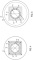
- the detent 150 exhibits a first cross-sectional geometry G d as illustrated in FIG. 4 .
- the cross-sectional geometry G d of the detent 150 may exhibit a largest linear dimension that is greater than the largest linear dimension exhibited by the cross-sectional geometry G s of locking pin shank 152.
- the cross-sectional geometry G d of the detent 150 may also exhibit at least one angular portion having an angle of less than 180 degrees, and preferably, less than 90 degrees.
- the cross-sectional geometry is polygonal. As illustrated, the cross-sectional geometry assumes the shape of a square. Alternatively, the cross-sectional geometry may assume the shape of a half-circle, rectangle, triangle, pentagon, hexagon, heptagon, octagon, or star. In further alternative embodiments, the cross-sectional geometry may be elliptical or tear dropped shaped.
- the locking pin shank 152 extending from either side of the detent 150 may assume any geometry, such as circular, elliptical, square, etc.
- the locking hole 142 in which the locking pin 140 is positioned, includes a locking cavity 160.
- the locking cavity 160 accommodates the detent 150 and, as seen in FIG. 5 , the locking cavity 160 exhibits a larger cross-sectional geometry G c than the cross-sectional geometry G t of the bores 162, 164 extending from either side of the locking cavity 160.
- the transition between the locking cavity 160 and the bores 162, 164 forms shoulders 166 (see FIGS. 2 & 3 ), which form stops and retain the detent 150 within the locking cavity 160.
- At least one surface of the locking cavity 160 interferes with the detent 150 to prevent rotation of the detent 150.
- the locking cavity 160 exhibits the same or a similar cross-sectional geometry G c (within 5% of the dimensions) as the cross-sectional geometry G d of the detent 150, see FIG. 4 .
- the locking cavity 160 is formed in both the first elongated half 102 and the second elongated half 104, so that the detent 150 of the locking pin may be positioned in either of the elongated halves, one of the elongated halves, or in both elongated halves.
- the detent 150 When the locking pin 140 is in the locked position, the detent 150 is positioned in a location in the locking cavity 160 where the detent 150 is positioned in both the first elongated half 102 and the second elongated half 104, as seen in FIG. 2 . In such a manner, the detent 150 impedes the ability of the first elongated half 102 to rotate relative to the second elongated half 104.
- FIG. 3 illustrates that when the locking pin 140 is in the unlocked position, the detent 150 is located only within one of the two elongated halves. As illustrated, the detent is located only in the second elongated half 104. Alternatively, the detent may be positioned in only the first elongated half 102 and the first bore 162.
- Positioning the detent in the second elongated half 104 allows the first elongated half 102 to rotate relative to the second elongated half. Given that the detent 150 of the locking pin 140 may be retained in the second elongated half 104 when in the unlocked position, the second elongated half 104 may not rotate relative to the locking pin 140.
- the longest linear dimension L s of the cross-sectional geometry G s of the locking pin shank 152 may be smaller than the longest linear dimension L d of the cross-sectional geometry G d of the detent 150, see FIG. 4 .
- the longest linear dimension L s of the cross-sectional geometry G s of the locking pin shank may be smaller than the smallest linear dimension L b of the cross-sectional geometry G b of the bore 162 as illustrated in FIG. 5 . This allows the shank to rotate in the bores 162, 164, particularly when the locking pin is in the unlocked position and the first elongated half 102 may rotate around the locking pin 140.
- the first elongated half 102 and the second elongated half 104 of the chew toy 100 may be locked in a variety of positions around the axis or rotation A-A.
- the first elongated half 102 may be locked in four different positions relative to the second elongated half 104. In two of the locking positions, which are 180 degrees from each other around the axis of rotation A-A, the first elongated half 102 may overly the second elongated half 104 such that they are substantially coextensive or parallel with each other.
- the first elongate half 102 may overly the second elongated half 104 such that the halves are perpendicular to each other.
- the number of locking positions may be determined by the number of sides or elongated portions present. For example, if three sides are present, where the detent and locking cavity are in the shape of a triangle, the elongated halves may have three locking positions. Where the detent and locking cavity are in the shape of a pentagon, the elongated halves may have five locking positions. If the detent and locking cavity are in the shape of an ellipse, the elongated halves may have two locking positions, etc.
- a track 170 and guide 172 may be provided on the adjoining surfaces 116, 118 of the first elongated half 102 and the second elongated half 104.
- the track 170 is formed in the surface 116 of the first elongated half 102 and the guide 172 extends from a surface 118 of the second elongated half 104 and is received in the track 170.
- the track may be formed in the surface of the second elongated half and the guide may extend from the surface of the first elongated half.
- the track may be circular in shape and concentric to the axis of rotation A-A.
- the guide may also be circular in shape and concentric to the axis of rotation A-A. However, as illustrated in FIG.
- the guides 172 may also be formed of one or more projections that assume the shape of a hemisphere that extend from the surface opposing the track and are received in the track.
- the track and guide may assist in maintaining alignment between the two elongated halves as the halves rotate relative to each other. Further, when the track and guide are circular, the track and guide may act as a seal preventing residue from treats held by the chew 100 from passing into the hub area 110 and fouling the rotational movement of the elongated halves 102, 104 relative to each other.
- the chew 100 includes one or more chambers 180, 182 for retaining treats 184, 186.
- the treats 184, 186 may be, at least partially, inserted into the opening and may extend from the opening.
- the treats 184, 186 may be edible treats, including biscuits, smaller chews, or pastes such as peanut butter or dental paste. Smaller chews may include those made from rawhide, vegetable flours, vegetable starches, vegetable proteins, grain flours, grain starches, or grain proteins.
- the chambers 180, 182 are formed in the first and second elongated half 104 of the chew 100.
- Each chamber 180, 182 include an interior volume 188, 190 and an opening 192, 194, which provides communication between the interior volume 188, 190 and the exterior of the chew 100 when the halves of the chew are aligned.
- the interior volume is enclosed by the first and second elongated halves except for at the opening 192, 194.
- the halves of the chew 100 are offset, such as when they are perpendicular to each other, the interior volume 188, 190 of the chambers are exposed. This makes it easier to clean the chambers of the chew and remove any residual particles or pastes that may have been deposited by treats 184, 186 inserted into the chambers 180, 182.
- the upper portion of the chambers 196, 198 in the first elongated half 102 may not only provide space for the insertion of a treat but may also reduce the wall thickness of the first elongated half 102. This may reduce cooling time and stresses after molding the elongated half 102 out of a polymer material.
- the lower portion of the chambers 200, 202 may similarly reduce cooling time and stresses after molding the second elongated half 104 out a polymer material.
- the lower portion of the chambers 200, 202 may exhibit a similar geometry as a treat 184, 186 that is to be inserted into the chamber.
- the upper portion of the chambers 196, 198 may also or alternatively exhibit a similar geometry as the treat to be inserted into the chamber 180, 182.
- the treat is positioned in only one of the two portions 200, 202 of the chamber. Further, as illustrated, the treat is located only in the lower half of the chamber 200, 202 defined in the second elongated half 104. However, in alternative embodiments, the treats 184, 186 may be located in only the upper portions 196, 198 of the chamber defined in the first elongated half 102.
- At least one cross-sectional dimension of the opening may be smaller than the corresponding cross-sectional dimension of the chamber.
- the height of the opening H o may be smaller than the height of the chamber H c .
- the width of the opening W o may be smaller than the width of the chamber W c .
- both the height of the opening may be smaller than the height of the chamber and the width of the opening may be smaller than the width of the chamber.
- the portion of the treat 184, 186 that is inserted into the interior volume of a chamber 180, 182 may exhibit a height H t , width W t , or both height and width that is larger than the height, width or both height H o of the opening and width W o of the opening.
- This arrangement, where the width or height of the portion of the treat inserted into the interior volume of the chamber is larger than the height or width of the opening may assist in retaining the treat within the interior volume of the chamber 180, 182, at least until the pet has worn the surfaces of the treat away.
- a treat inserted into either of the chambers 180, 182 may exhibit a different set of mechanical properties than the chew 100.
- Mechanical properties may include Young's modulus, tensile strength, hardness, wear resistance, and flexural modulus. At least one of the properties may differ to create a different set of mechanical properties.
- the hardness of the treat retained in the chew may be in the range of 70 to 90 Shore A and the chew 100 may exhibit a hardness in the range of 10 to 89 Shore D, including all values and ranges therein.
- the treat retained in the chew may exhibit a ultimate tensile strength of less than 10,000 psi and the chew 100 may exhibit an ultimate tensile strength of 10,000 psi or greater.
- a first recess 210 may be provided in the external surface 212 of the first elongated half 102 and a second recess 214 may be provided in the external surface 216 of the second elongated half 104.
- the recesses 210, 212 may be concentric with the axis of rotation A-A.
- the bores 162, 164 may open into the bottom of the recesses 210, 214 providing communication from the locking cavity to the recesses 210, 214.
- the shank 152 of the locking pin 140 may extend through the bores 162, 164 into the recesses 210, 214.
- the recesses 210, 214 may prevent the force from being applied to the locking pin shank 152, particularly if the force is applied by an object that is larger than the opening 218, 220 of the recesses at the external surfaces 212, 216 of the chew 100.
- the present disclosure also relates to a method of operating a pet chew and feeding a pet treats with the pet chew.
- the method may include inserting a treat at least partially in one of the chambers and rotating the elongated halves relative to each other such that the interior volume of the chamber is enclosed by the elongated halves, although the opening may be left exposed.
- the method may further include positioning the locking pin in a locked position, impeding the rotation of the two elongated halves relative to each other. Prior to inserting the treat into the chew, one may need to position the locking pin in the unlocked position and rotating the first half relative to the second half to expose the interior volume of the chamber in which the treat will be positioned. Further, one may need to clean the interior volume of the chamber out, which may be performed when the interior volume of the chamber is exposed.
- the present invention relates to assembling the pet chew together.
- the two elongated halves 102, 104 may be formed by a variety of forming processes such as milling a piece of solid stock or molding the chew by a melt processing method.
- the locking pin is inserted into the hole formed in of the first and second elongated halves.
- the flange of one half is inserted into the channel formed in the other half.
- the retention features provided on both halves interlock and cause the first and second half to be secured so they cannot be separated.
- the elongated halves may rotate relative to each other.
Landscapes
- Life Sciences & Earth Sciences (AREA)
- Health & Medical Sciences (AREA)
- Environmental Sciences (AREA)
- Physical Education & Sports Medicine (AREA)
- General Health & Medical Sciences (AREA)
- Animal Behavior & Ethology (AREA)
- Zoology (AREA)
- Animal Husbandry (AREA)
- Biodiversity & Conservation Biology (AREA)
- Dentistry (AREA)
- Fodder In General (AREA)
- Feeding And Watering For Cattle Raising And Animal Husbandry (AREA)
- Housing For Livestock And Birds (AREA)
- Toys (AREA)
Claims (10)
- Kauartikel (100) für Tiere, umfassend:eine erste längliche Hälfte (102);eine zweite längliche Hälfte (104), die drehbar an der ersten länglichen Hälfte (102) befestigt ist, wobei die erste längliche Hälfte (102) und die zweite längliche Hälfte (104) sich um eine Drehachse (A-A) drehen;einen Verriegelungsstift (140), der entlang der Drehachse (A-A) ausgerichtet ist und zwischen der ersten länglichen Hälfte (102) und der zweiten länglichen Hälfte (104) gehalten wird, wobei der Verriegelungsstift (140) eine Arretierung (150) aufweist, die eine Querschnittsgeometrie (Gd) aufweist, wobei der Verriegelungsstift (140) auf der Drehachse (A-A) auf und ab in eine verriegelte Position und eine entriegelte Position gleitet;ein Verriegelungsloch (142) zur Aufnahme des Verriegelungsstifts (140), wobei sich das Verriegelungsloch (142) durch die erste längliche Hälfte (102) und die zweite längliche Hälfte (104) erstreckt, wobei das Verriegelungsloch (142) einen Verriegelungshohlraum (160) mit einer Querschnittsgeometrie (Gc) aufweist, die der Querschnittsgeometrie (Gd) des Riegels (150) ähnlich ist, wobei der Verriegelungshohlraum (160) sowohl in der ersten länglichen Hälfte (102) als auch in der zweiten länglichen Hälfte (104) vorhanden ist, wobei mindestens eine Oberfläche des Verriegelungshohlraums (160) mit dem Rastelement (150) zusammenwirkt, um eine Drehung des Rastelements (150) zu verhindern; undeine Kammer (180, 182) mit einer Öffnung (192, 194) und einem Innenvolumen (188, 190), wobei die Kammer (180, 182) in mindestens einer der ersten länglichen Hälfte (102) und der zweiten länglichen Hälfte (104) ausgebildet ist;wobei, wenn sich der Verriegelungsstift (140) in der verriegelten Position befindet, die Drehung der ersten länglichen Hälfte (102) relativ zu der zweiten länglichen Hälfte (104) verhindert wird, und wobei, wenn sich der Verriegelungsstift (140) in der entriegelten Position befindet, die Arretierung (150) nur innerhalb der ersten länglichen Hälfte (102) oder der zweiten länglichen Hälfte (104) positioniert ist, so dass sich die erste längliche Hälfte (102) relativ zu der zweiten längliche Hälfte (104) drehen kann;wobei eine der ersten länglichen Hälfte (102) und der zweiten länglichen Hälfte (104) einen Flansch (112) mit einem Rückhaltemerkmal (132) umfasst und die andere der länglichen Hälften einen Kanal (114) mit einem weiteren Rückhaltemerkmal (130) umfasst, um die erste längliche Hälfte (102) relativ zu der zweiten länglichen Hälfte (104) durch Aufnahme des Flansches (112) in dem Kanal (114) zu sichern.
- Kauartikel (100) nach Anspruch 1, wobei sich der Flansch (112) von der ersten länglichen Hälfte (102) aus erstreckt und der Kanal (114) in der zweiten länglichen Hälfte (104) ausgebildet ist.
- Kauartikel (100) nach Anspruch 2, wobei die Rückhalteelemente (130, 132) eine Zunge (130), die sich von dem Kanal (114) erstreckt, und eine Nut (132) in dem Flansch (112) umfassen, wobei die Zunge (130) in der Nut (132) aufgenommen wird.
- Kauartikel (100) nach einem der Ansprüche 1 bis 3, der ferner eine in der ersten länglichen Hälfte (102) ausgebildete Spur (170) und eine sich von der zweiten länglichen Hälfte (104) erstreckende Führung (172) aufweist, wobei die Führung (172) in der Spur (170) aufgenommen ist.
- Kauartikel (100) nach einem der Ansprüche 1 bis 4, wobei die erste längliche Hälfte (102) und die zweite längliche Hälfte (104) eine Nabe (110) und mindestens zwei Arme (106, 108) definieren, die sich von der Nabe (110) aus erstrecken, wobei die Nabe (110) konzentrisch zu der Drehachse (A-A) ist, wobei jeder der Arme (106, 108) vorzugsweise die Kammer (180, 182) enthält.
- Kauartikel (100) nach einem der Ansprüche 1 bis 5, der ferner ein Leckerli (184, 186) umfasst, das zumindest teilweise in das Innenvolumen (188, 190) der Kammer (180, 182) eingeführt ist.
- Kauartikel (100) nach Anspruch 6, wobei sich der Leckerbissen (184, 186) durch die Öffnung (192, 194) erstreckt, wobei der Leckerbissen (184, 186) essbar ist.
- Kauartikel (100) nach einem der Ansprüche 1 bis 7, wobei die Querschnittsgeometrie (Gd) der Arretierung (150) polygonal oder quadratisch ist.
- Kauartikel (100) nach einem der Ansprüche 1 bis 8, wobei der Verriegelungsstift (140) in der entriegelten Position nicht relativ zu der ersten länglichen Hälfte (102) oder der zweiten länglichen Hälfte (104) drehbar ist.
- Verfahren zum Zusammenbau eines Kauspielzeugs für Tiere, das die folgenden Schritte umfasst:Bereitstellung des Kauartikels (100) für Tiere nach einem der Ansprüche 1 bis 9;Positionieren des Verriegelungsstifts (140) einschließlich der Arretierung (150) mit einer Querschnittsgeometrie (Gd) in dem Loch (142) einschließlich eines Verriegelungshohlraums (160) mit einer Querschnittsgeometrie (Gc), die der Querschnittsgeometrie (Gd) der Arretierung (150) ähnlich ist, wobei der Verriegelungshohlraum (160) sowohl in der ersten länglichen Hälfte (102) als auch in der zweiten länglichen Hälfte (104) ausgebildet ist, wobei, wenn sich der Verriegelungsstift (140) in einer verriegelten Position befindet, die Drehung der ersten länglichen Hälfte (102) relativ zu der zweiten länglichen Hälfte (104) behindert ist, und wobei, wenn sich der Verriegelungsstift (140) in der entriegelten Position befindet, die Arretierung (150) nur innerhalb der ersten länglichen Hälfte (102) oder der zweiten länglichen Hälfte (104) positioniert ist, wodurch die erste längliche Hälfte (102) sich relativ zu der zweiten länglichen Hälfte (104) drehen kann;Einsetzen eines Flansches (112), der sich von einer der länglichen Hälften (102, 104) aus erstreckt, in einen Kanal (114), der in der anderen der länglichen Hälften (102, 104) definiert ist; undin ein Rückhalteelement (130, 132) eingreift und die erste längliche Hälfte (102) relativ zu der zweiten länglichen Hälfte (104) sichert.
Applications Claiming Priority (2)
| Application Number | Priority Date | Filing Date | Title |
|---|---|---|---|
| US14/518,450 US9554561B2 (en) | 2014-10-20 | 2014-10-20 | Locking rotating chew |
| PCT/US2015/056305 WO2016064778A1 (en) | 2014-10-20 | 2015-10-20 | Locking rotating chew |
Publications (3)
| Publication Number | Publication Date |
|---|---|
| EP3209119A1 EP3209119A1 (de) | 2017-08-30 |
| EP3209119A4 EP3209119A4 (de) | 2018-07-11 |
| EP3209119B1 true EP3209119B1 (de) | 2023-09-06 |
Family
ID=55747960
Family Applications (1)
| Application Number | Title | Priority Date | Filing Date |
|---|---|---|---|
| EP15853206.9A Active EP3209119B1 (de) | 2014-10-20 | 2015-10-20 | Verriegelung eines rotierenden kauspielzeugs |
Country Status (7)
| Country | Link |
|---|---|
| US (1) | US9554561B2 (de) |
| EP (1) | EP3209119B1 (de) |
| CN (1) | CN107072172B (de) |
| AU (1) | AU2015336149B2 (de) |
| CA (1) | CA2965320C (de) |
| ES (1) | ES2959482T3 (de) |
| WO (1) | WO2016064778A1 (de) |
Families Citing this family (17)
| Publication number | Priority date | Publication date | Assignee | Title |
|---|---|---|---|---|
| US10051838B2 (en) * | 2015-04-23 | 2018-08-21 | The Kong Company, Llc | Pet toy with variable elasticity |
| USD815780S1 (en) * | 2016-05-20 | 2018-04-17 | Paragon Pet Products Europe B.V. | Dog chew toy |
| USD817561S1 (en) * | 2016-07-11 | 2018-05-08 | Paragon Pet Products Europe B.V. | Dog chew toy |
| KR101820411B1 (ko) * | 2016-08-29 | 2018-01-19 | 김창섭 | 애완동물용 저작 보조 기구 |
| US11477965B2 (en) * | 2017-01-31 | 2022-10-25 | Pup Dog, Llc | Securing device for animal chew |
| USD843680S1 (en) * | 2018-02-21 | 2019-03-26 | Towerstar Pets, Llc | Pet chew toy |
| US10888069B2 (en) | 2017-11-07 | 2021-01-12 | Towerstar Pets, Llc | Pet toy including apertures for receiving treats |
| US11382311B2 (en) * | 2018-07-03 | 2022-07-12 | Willinger Development LLC | Destruction resistant pet toy with attractant and method of making same |
| WO2020102719A1 (en) * | 2018-11-16 | 2020-05-22 | Bow Wow Labs, Inc. | Pet treat holder and safety device |
| US10905098B2 (en) * | 2018-12-07 | 2021-02-02 | Bounce, Inc. | Animal feeder, combination feeder and toy, and method of entertaining an animal |
| USD881480S1 (en) * | 2019-12-06 | 2020-04-14 | Guangzhou Jinyu outdoor products Co., Ltd. | Cat toothbrush |
| USD908294S1 (en) * | 2020-06-15 | 2021-01-19 | Shenzhenshi yuanhuili keji youxian gongsi | Dog squeaky chew toy |
| US11464208B2 (en) * | 2020-12-10 | 2022-10-11 | Lisa Weller | Pet toy with chew holder |
| US20220312737A1 (en) * | 2021-04-05 | 2022-10-06 | Chewsy Pets, LLC | Pet Chew Toy |
| KR102577115B1 (ko) * | 2021-06-02 | 2023-09-08 | 김창섭 | 애완동물용 저작보조기구 |
| DE202022101730U1 (de) * | 2022-03-31 | 2022-05-12 | Julia Davids | Beschäftigungsvorrichtung für Haustiere |
| CN218457043U (zh) * | 2022-10-24 | 2023-02-10 | 广东铭锋科技有限公司 | 宠物啃咬玩具 |
Family Cites Families (17)
| Publication number | Priority date | Publication date | Assignee | Title |
|---|---|---|---|---|
| US5806465A (en) * | 1997-04-03 | 1998-09-15 | J.W. Pet Company, Inc. | Pet toy |
| DE29821473U1 (de) * | 1998-12-01 | 1999-04-08 | Wang, Steve Yueh-Yu, Taipeh/T'ai-pei | Hundefutter abgebendes Hundespielzeug |
| US6155902A (en) | 1999-10-26 | 2000-12-05 | Kole, Jr.; James S. | Push toy scooter wagon |
| CA2504034C (en) | 2002-11-13 | 2011-01-11 | Premier Pet Products, Llc | Treat retaining pet toy and treats therefor |
| US20040134446A1 (en) * | 2003-01-10 | 2004-07-15 | Steve Keller | Dog toy |
| US7063044B2 (en) * | 2004-01-12 | 2006-06-20 | The Hartz Mountain Corporation | Multipart chew toy |
| US20060225667A1 (en) | 2005-04-06 | 2006-10-12 | Simon Handelsman | Flexible configuration dog bone |
| US20070022971A1 (en) | 2005-07-26 | 2007-02-01 | Renforth Jack W | Pet treat-dispensing toy |
| US7810455B2 (en) * | 2007-10-10 | 2010-10-12 | T.F.H. Publications, Inc. | Pet chew including compressible central portion |
| US20090217885A1 (en) | 2008-03-03 | 2009-09-03 | Steven Edward Peter | Pet treat holder toy |
| US20090255482A1 (en) | 2008-04-11 | 2009-10-15 | Aspen Pet Products, Inc. | Pet toy |
| US20120000059A1 (en) * | 2010-07-03 | 2012-01-05 | Nathaniel Fox | Object Connector |
| US8935992B2 (en) | 2011-02-11 | 2015-01-20 | T.F.H. Publications, Inc. | Animal chew including interchangeable components |
| US8746182B2 (en) * | 2011-06-17 | 2014-06-10 | Jw Pet Company, Inc. | Treat dispenser |
| US20130008389A1 (en) * | 2011-07-05 | 2013-01-10 | Ainsworth Pet Nutrition | Chew toy with edible piece |
| US8820268B2 (en) * | 2011-09-01 | 2014-09-02 | Jw Pet Company, Inc. | Treat dispenser |
| CN202979873U (zh) | 2012-11-28 | 2013-06-12 | 冯卫忠 | 一种漏食球 |
-
2014
- 2014-10-20 US US14/518,450 patent/US9554561B2/en active Active
-
2015
- 2015-10-20 WO PCT/US2015/056305 patent/WO2016064778A1/en not_active Ceased
- 2015-10-20 CN CN201580056891.5A patent/CN107072172B/zh active Active
- 2015-10-20 CA CA2965320A patent/CA2965320C/en active Active
- 2015-10-20 AU AU2015336149A patent/AU2015336149B2/en active Active
- 2015-10-20 EP EP15853206.9A patent/EP3209119B1/de active Active
- 2015-10-20 ES ES15853206T patent/ES2959482T3/es active Active
Also Published As
| Publication number | Publication date |
|---|---|
| CN107072172A (zh) | 2017-08-18 |
| CA2965320A1 (en) | 2016-04-28 |
| AU2015336149A1 (en) | 2017-04-27 |
| EP3209119A4 (de) | 2018-07-11 |
| CN107072172B (zh) | 2020-07-24 |
| CA2965320C (en) | 2022-12-20 |
| ES2959482T3 (es) | 2024-02-26 |
| US20160106068A1 (en) | 2016-04-21 |
| AU2015336149B2 (en) | 2019-05-16 |
| EP3209119A1 (de) | 2017-08-30 |
| US9554561B2 (en) | 2017-01-31 |
| WO2016064778A1 (en) | 2016-04-28 |
Similar Documents
| Publication | Publication Date | Title |
|---|---|---|
| EP3209119B1 (de) | Verriegelung eines rotierenden kauspielzeugs | |
| US20110156307A1 (en) | Chewable animal toy | |
| EP1919277B1 (de) | Leckereienhaltevorrichtung für haustiere | |
| US8464666B2 (en) | Dog toy ball dual treat holder | |
| AU2011316635B2 (en) | Pet toy with core assembly incorporating noise making feature | |
| US9924703B2 (en) | Releasable twist locking interface | |
| JP5255641B2 (ja) | 交換可能なトリートを保持するペット用玩具 | |
| US20140345532A1 (en) | Treat Dispenser | |
| US7640894B2 (en) | Treat dispenser for animals | |
| CN106106239B (zh) | 宠物零食递送系统 | |
| EP1863339B1 (de) | Behältervorrichtung, behälterverschluss und verfahren | |
| US20130074780A1 (en) | Multi-function pet toy | |
| US8464665B1 (en) | Pet toy convertible between a bone shape and a ball shape | |
| US12402602B1 (en) | Pet toy with adjustable food item holder | |
| US20180153139A1 (en) | System and method for producing toy balls for pets | |
| US10716290B1 (en) | Protective housing for dog chews | |
| US10945413B2 (en) | Randomly bouncing toy ball for pets such as dogs and production method | |
| US12376568B2 (en) | Refillable dog puzzle chew toy fabricated for powerful dog chewers | |
| WO2025245621A1 (en) | A treat retaining pet chew toy | |
| HK1227624A1 (en) | Pet treat delivery systems |
Legal Events
| Date | Code | Title | Description |
|---|---|---|---|
| STAA | Information on the status of an ep patent application or granted ep patent |
Free format text: STATUS: THE INTERNATIONAL PUBLICATION HAS BEEN MADE |
|
| PUAI | Public reference made under article 153(3) epc to a published international application that has entered the european phase |
Free format text: ORIGINAL CODE: 0009012 |
|
| STAA | Information on the status of an ep patent application or granted ep patent |
Free format text: STATUS: REQUEST FOR EXAMINATION WAS MADE |
|
| 17P | Request for examination filed |
Effective date: 20170522 |
|
| AK | Designated contracting states |
Kind code of ref document: A1 Designated state(s): AL AT BE BG CH CY CZ DE DK EE ES FI FR GB GR HR HU IE IS IT LI LT LU LV MC MK MT NL NO PL PT RO RS SE SI SK SM TR |
|
| AX | Request for extension of the european patent |
Extension state: BA ME |
|
| DAV | Request for validation of the european patent (deleted) | ||
| DAX | Request for extension of the european patent (deleted) | ||
| A4 | Supplementary search report drawn up and despatched |
Effective date: 20180608 |
|
| RIC1 | Information provided on ipc code assigned before grant |
Ipc: A01K 15/02 20060101AFI20180604BHEP |
|
| RAP1 | Party data changed (applicant data changed or rights of an application transferred) |
Owner name: T.F.H. PUBLICATIONS, INC. |
|
| STAA | Information on the status of an ep patent application or granted ep patent |
Free format text: STATUS: EXAMINATION IS IN PROGRESS |
|
| 17Q | First examination report despatched |
Effective date: 20210111 |
|
| GRAP | Despatch of communication of intention to grant a patent |
Free format text: ORIGINAL CODE: EPIDOSNIGR1 |
|
| STAA | Information on the status of an ep patent application or granted ep patent |
Free format text: STATUS: GRANT OF PATENT IS INTENDED |
|
| INTG | Intention to grant announced |
Effective date: 20230330 |
|
| GRAJ | Information related to disapproval of communication of intention to grant by the applicant or resumption of examination proceedings by the epo deleted |
Free format text: ORIGINAL CODE: EPIDOSDIGR1 |
|
| GRAP | Despatch of communication of intention to grant a patent |
Free format text: ORIGINAL CODE: EPIDOSNIGR1 |
|
| INTG | Intention to grant announced |
Effective date: 20230511 |
|
| GRAS | Grant fee paid |
Free format text: ORIGINAL CODE: EPIDOSNIGR3 |
|
| GRAA | (expected) grant |
Free format text: ORIGINAL CODE: 0009210 |
|
| STAA | Information on the status of an ep patent application or granted ep patent |
Free format text: STATUS: THE PATENT HAS BEEN GRANTED |
|
| AK | Designated contracting states |
Kind code of ref document: B1 Designated state(s): AL AT BE BG CH CY CZ DE DK EE ES FI FR GB GR HR HU IE IS IT LI LT LU LV MC MK MT NL NO PL PT RO RS SE SI SK SM TR |
|
| REG | Reference to a national code |
Ref country code: GB Ref legal event code: FG4D |
|
| REG | Reference to a national code |
Ref country code: CH Ref legal event code: EP |
|
| REG | Reference to a national code |
Ref country code: IE Ref legal event code: FG4D |
|
| REG | Reference to a national code |
Ref country code: DE Ref legal event code: R096 Ref document number: 602015085607 Country of ref document: DE |
|
| RAP4 | Party data changed (patent owner data changed or rights of a patent transferred) |
Owner name: T.F.H. PUBLICATIONS, INC. |
|
| P01 | Opt-out of the competence of the unified patent court (upc) registered |
Effective date: 20231016 |
|
| REG | Reference to a national code |
Ref country code: LT Ref legal event code: MG9D |
|
| REG | Reference to a national code |
Ref country code: NL Ref legal event code: MP Effective date: 20230906 |
|
| PG25 | Lapsed in a contracting state [announced via postgrant information from national office to epo] |
Ref country code: GR Free format text: LAPSE BECAUSE OF FAILURE TO SUBMIT A TRANSLATION OF THE DESCRIPTION OR TO PAY THE FEE WITHIN THE PRESCRIBED TIME-LIMIT Effective date: 20231207 |
|
| PG25 | Lapsed in a contracting state [announced via postgrant information from national office to epo] |
Ref country code: SE Free format text: LAPSE BECAUSE OF FAILURE TO SUBMIT A TRANSLATION OF THE DESCRIPTION OR TO PAY THE FEE WITHIN THE PRESCRIBED TIME-LIMIT Effective date: 20230906 Ref country code: RS Free format text: LAPSE BECAUSE OF FAILURE TO SUBMIT A TRANSLATION OF THE DESCRIPTION OR TO PAY THE FEE WITHIN THE PRESCRIBED TIME-LIMIT Effective date: 20230906 Ref country code: NO Free format text: LAPSE BECAUSE OF FAILURE TO SUBMIT A TRANSLATION OF THE DESCRIPTION OR TO PAY THE FEE WITHIN THE PRESCRIBED TIME-LIMIT Effective date: 20231206 Ref country code: LV Free format text: LAPSE BECAUSE OF FAILURE TO SUBMIT A TRANSLATION OF THE DESCRIPTION OR TO PAY THE FEE WITHIN THE PRESCRIBED TIME-LIMIT Effective date: 20230906 Ref country code: LT Free format text: LAPSE BECAUSE OF FAILURE TO SUBMIT A TRANSLATION OF THE DESCRIPTION OR TO PAY THE FEE WITHIN THE PRESCRIBED TIME-LIMIT Effective date: 20230906 Ref country code: HR Free format text: LAPSE BECAUSE OF FAILURE TO SUBMIT A TRANSLATION OF THE DESCRIPTION OR TO PAY THE FEE WITHIN THE PRESCRIBED TIME-LIMIT Effective date: 20230906 Ref country code: GR Free format text: LAPSE BECAUSE OF FAILURE TO SUBMIT A TRANSLATION OF THE DESCRIPTION OR TO PAY THE FEE WITHIN THE PRESCRIBED TIME-LIMIT Effective date: 20231207 Ref country code: FI Free format text: LAPSE BECAUSE OF FAILURE TO SUBMIT A TRANSLATION OF THE DESCRIPTION OR TO PAY THE FEE WITHIN THE PRESCRIBED TIME-LIMIT Effective date: 20230906 |
|
| REG | Reference to a national code |
Ref country code: AT Ref legal event code: MK05 Ref document number: 1607221 Country of ref document: AT Kind code of ref document: T Effective date: 20230906 |
|
| REG | Reference to a national code |
Ref country code: ES Ref legal event code: FG2A Ref document number: 2959482 Country of ref document: ES Kind code of ref document: T3 Effective date: 20240226 |
|
| PG25 | Lapsed in a contracting state [announced via postgrant information from national office to epo] |
Ref country code: NL Free format text: LAPSE BECAUSE OF FAILURE TO SUBMIT A TRANSLATION OF THE DESCRIPTION OR TO PAY THE FEE WITHIN THE PRESCRIBED TIME-LIMIT Effective date: 20230906 |
|
| PG25 | Lapsed in a contracting state [announced via postgrant information from national office to epo] |
Ref country code: IS Free format text: LAPSE BECAUSE OF FAILURE TO SUBMIT A TRANSLATION OF THE DESCRIPTION OR TO PAY THE FEE WITHIN THE PRESCRIBED TIME-LIMIT Effective date: 20240106 |
|
| PG25 | Lapsed in a contracting state [announced via postgrant information from national office to epo] |
Ref country code: AT Free format text: LAPSE BECAUSE OF FAILURE TO SUBMIT A TRANSLATION OF THE DESCRIPTION OR TO PAY THE FEE WITHIN THE PRESCRIBED TIME-LIMIT Effective date: 20230906 |
|
| PG25 | Lapsed in a contracting state [announced via postgrant information from national office to epo] |
Ref country code: SM Free format text: LAPSE BECAUSE OF FAILURE TO SUBMIT A TRANSLATION OF THE DESCRIPTION OR TO PAY THE FEE WITHIN THE PRESCRIBED TIME-LIMIT Effective date: 20230906 Ref country code: RO Free format text: LAPSE BECAUSE OF FAILURE TO SUBMIT A TRANSLATION OF THE DESCRIPTION OR TO PAY THE FEE WITHIN THE PRESCRIBED TIME-LIMIT Effective date: 20230906 Ref country code: IS Free format text: LAPSE BECAUSE OF FAILURE TO SUBMIT A TRANSLATION OF THE DESCRIPTION OR TO PAY THE FEE WITHIN THE PRESCRIBED TIME-LIMIT Effective date: 20240106 Ref country code: EE Free format text: LAPSE BECAUSE OF FAILURE TO SUBMIT A TRANSLATION OF THE DESCRIPTION OR TO PAY THE FEE WITHIN THE PRESCRIBED TIME-LIMIT Effective date: 20230906 Ref country code: CZ Free format text: LAPSE BECAUSE OF FAILURE TO SUBMIT A TRANSLATION OF THE DESCRIPTION OR TO PAY THE FEE WITHIN THE PRESCRIBED TIME-LIMIT Effective date: 20230906 Ref country code: AT Free format text: LAPSE BECAUSE OF FAILURE TO SUBMIT A TRANSLATION OF THE DESCRIPTION OR TO PAY THE FEE WITHIN THE PRESCRIBED TIME-LIMIT Effective date: 20230906 Ref country code: SK Free format text: LAPSE BECAUSE OF FAILURE TO SUBMIT A TRANSLATION OF THE DESCRIPTION OR TO PAY THE FEE WITHIN THE PRESCRIBED TIME-LIMIT Effective date: 20230906 Ref country code: PT Free format text: LAPSE BECAUSE OF FAILURE TO SUBMIT A TRANSLATION OF THE DESCRIPTION OR TO PAY THE FEE WITHIN THE PRESCRIBED TIME-LIMIT Effective date: 20240108 |
|
| PG25 | Lapsed in a contracting state [announced via postgrant information from national office to epo] |
Ref country code: PL Free format text: LAPSE BECAUSE OF FAILURE TO SUBMIT A TRANSLATION OF THE DESCRIPTION OR TO PAY THE FEE WITHIN THE PRESCRIBED TIME-LIMIT Effective date: 20230906 |
|
| REG | Reference to a national code |
Ref country code: CH Ref legal event code: PL |
|
| REG | Reference to a national code |
Ref country code: DE Ref legal event code: R097 Ref document number: 602015085607 Country of ref document: DE |
|
| REG | Reference to a national code |
Ref country code: BE Ref legal event code: MM Effective date: 20231031 |
|
| PG25 | Lapsed in a contracting state [announced via postgrant information from national office to epo] |
Ref country code: LU Free format text: LAPSE BECAUSE OF NON-PAYMENT OF DUE FEES Effective date: 20231020 |
|
| PG25 | Lapsed in a contracting state [announced via postgrant information from national office to epo] |
Ref country code: LU Free format text: LAPSE BECAUSE OF NON-PAYMENT OF DUE FEES Effective date: 20231020 |
|
| PG25 | Lapsed in a contracting state [announced via postgrant information from national office to epo] |
Ref country code: MC Free format text: LAPSE BECAUSE OF FAILURE TO SUBMIT A TRANSLATION OF THE DESCRIPTION OR TO PAY THE FEE WITHIN THE PRESCRIBED TIME-LIMIT Effective date: 20230906 |
|
| PG25 | Lapsed in a contracting state [announced via postgrant information from national office to epo] |
Ref country code: DK Free format text: LAPSE BECAUSE OF FAILURE TO SUBMIT A TRANSLATION OF THE DESCRIPTION OR TO PAY THE FEE WITHIN THE PRESCRIBED TIME-LIMIT Effective date: 20230906 |
|
| PLBE | No opposition filed within time limit |
Free format text: ORIGINAL CODE: 0009261 |
|
| STAA | Information on the status of an ep patent application or granted ep patent |
Free format text: STATUS: NO OPPOSITION FILED WITHIN TIME LIMIT |
|
| PG25 | Lapsed in a contracting state [announced via postgrant information from national office to epo] |
Ref country code: CH Free format text: LAPSE BECAUSE OF NON-PAYMENT OF DUE FEES Effective date: 20231031 |
|
| PG25 | Lapsed in a contracting state [announced via postgrant information from national office to epo] |
Ref country code: MC Free format text: LAPSE BECAUSE OF FAILURE TO SUBMIT A TRANSLATION OF THE DESCRIPTION OR TO PAY THE FEE WITHIN THE PRESCRIBED TIME-LIMIT Effective date: 20230906 Ref country code: DK Free format text: LAPSE BECAUSE OF FAILURE TO SUBMIT A TRANSLATION OF THE DESCRIPTION OR TO PAY THE FEE WITHIN THE PRESCRIBED TIME-LIMIT Effective date: 20230906 Ref country code: CH Free format text: LAPSE BECAUSE OF NON-PAYMENT OF DUE FEES Effective date: 20231031 Ref country code: SI Free format text: LAPSE BECAUSE OF FAILURE TO SUBMIT A TRANSLATION OF THE DESCRIPTION OR TO PAY THE FEE WITHIN THE PRESCRIBED TIME-LIMIT Effective date: 20230906 |
|
| 26N | No opposition filed |
Effective date: 20240607 |
|
| PG25 | Lapsed in a contracting state [announced via postgrant information from national office to epo] |
Ref country code: BE Free format text: LAPSE BECAUSE OF NON-PAYMENT OF DUE FEES Effective date: 20231031 |
|
| PG25 | Lapsed in a contracting state [announced via postgrant information from national office to epo] |
Ref country code: IE Free format text: LAPSE BECAUSE OF NON-PAYMENT OF DUE FEES Effective date: 20231020 |
|
| PG25 | Lapsed in a contracting state [announced via postgrant information from national office to epo] |
Ref country code: IE Free format text: LAPSE BECAUSE OF NON-PAYMENT OF DUE FEES Effective date: 20231020 |
|
| PG25 | Lapsed in a contracting state [announced via postgrant information from national office to epo] |
Ref country code: BG Free format text: LAPSE BECAUSE OF FAILURE TO SUBMIT A TRANSLATION OF THE DESCRIPTION OR TO PAY THE FEE WITHIN THE PRESCRIBED TIME-LIMIT Effective date: 20230906 |
|
| PG25 | Lapsed in a contracting state [announced via postgrant information from national office to epo] |
Ref country code: BG Free format text: LAPSE BECAUSE OF FAILURE TO SUBMIT A TRANSLATION OF THE DESCRIPTION OR TO PAY THE FEE WITHIN THE PRESCRIBED TIME-LIMIT Effective date: 20230906 |
|
| PG25 | Lapsed in a contracting state [announced via postgrant information from national office to epo] |
Ref country code: CY Free format text: LAPSE BECAUSE OF FAILURE TO SUBMIT A TRANSLATION OF THE DESCRIPTION OR TO PAY THE FEE WITHIN THE PRESCRIBED TIME-LIMIT; INVALID AB INITIO Effective date: 20151020 |
|
| PG25 | Lapsed in a contracting state [announced via postgrant information from national office to epo] |
Ref country code: HU Free format text: LAPSE BECAUSE OF FAILURE TO SUBMIT A TRANSLATION OF THE DESCRIPTION OR TO PAY THE FEE WITHIN THE PRESCRIBED TIME-LIMIT; INVALID AB INITIO Effective date: 20151020 |
|
| PG25 | Lapsed in a contracting state [announced via postgrant information from national office to epo] |
Ref country code: TR Free format text: LAPSE BECAUSE OF FAILURE TO SUBMIT A TRANSLATION OF THE DESCRIPTION OR TO PAY THE FEE WITHIN THE PRESCRIBED TIME-LIMIT Effective date: 20230906 |
|
| PGFP | Annual fee paid to national office [announced via postgrant information from national office to epo] |
Ref country code: DE Payment date: 20251029 Year of fee payment: 11 |
|
| PGFP | Annual fee paid to national office [announced via postgrant information from national office to epo] |
Ref country code: GB Payment date: 20251027 Year of fee payment: 11 |
|
| PGFP | Annual fee paid to national office [announced via postgrant information from national office to epo] |
Ref country code: IT Payment date: 20251021 Year of fee payment: 11 |
|
| PGFP | Annual fee paid to national office [announced via postgrant information from national office to epo] |
Ref country code: FR Payment date: 20251027 Year of fee payment: 11 |
|
| PGFP | Annual fee paid to national office [announced via postgrant information from national office to epo] |
Ref country code: ES Payment date: 20251103 Year of fee payment: 11 |