EP3208574A1 - Resolver stator - Google Patents
Resolver stator Download PDFInfo
- Publication number
- EP3208574A1 EP3208574A1 EP16206165.9A EP16206165A EP3208574A1 EP 3208574 A1 EP3208574 A1 EP 3208574A1 EP 16206165 A EP16206165 A EP 16206165A EP 3208574 A1 EP3208574 A1 EP 3208574A1
- Authority
- EP
- European Patent Office
- Prior art keywords
- coil
- radial direction
- guide
- connecting wire
- virtual plane
- Prior art date
- Legal status (The legal status is an assumption and is not a legal conclusion. Google has not performed a legal analysis and makes no representation as to the accuracy of the status listed.)
- Granted
Links
Images






Classifications
-
- G—PHYSICS
- G01—MEASURING; TESTING
- G01D—MEASURING NOT SPECIALLY ADAPTED FOR A SPECIFIC VARIABLE; ARRANGEMENTS FOR MEASURING TWO OR MORE VARIABLES NOT COVERED IN A SINGLE OTHER SUBCLASS; TARIFF METERING APPARATUS; MEASURING OR TESTING NOT OTHERWISE PROVIDED FOR
- G01D5/00—Mechanical means for transferring the output of a sensing member; Means for converting the output of a sensing member to another variable where the form or nature of the sensing member does not constrain the means for converting; Transducers not specially adapted for a specific variable
- G01D5/12—Mechanical means for transferring the output of a sensing member; Means for converting the output of a sensing member to another variable where the form or nature of the sensing member does not constrain the means for converting; Transducers not specially adapted for a specific variable using electric or magnetic means
- G01D5/14—Mechanical means for transferring the output of a sensing member; Means for converting the output of a sensing member to another variable where the form or nature of the sensing member does not constrain the means for converting; Transducers not specially adapted for a specific variable using electric or magnetic means influencing the magnitude of a current or voltage
- G01D5/20—Mechanical means for transferring the output of a sensing member; Means for converting the output of a sensing member to another variable where the form or nature of the sensing member does not constrain the means for converting; Transducers not specially adapted for a specific variable using electric or magnetic means influencing the magnitude of a current or voltage by varying inductance, e.g. by a movable armature
- G01D5/204—Mechanical means for transferring the output of a sensing member; Means for converting the output of a sensing member to another variable where the form or nature of the sensing member does not constrain the means for converting; Transducers not specially adapted for a specific variable using electric or magnetic means influencing the magnitude of a current or voltage by varying inductance, e.g. by a movable armature by influencing the mutual induction between two or more coils
-
- H—ELECTRICITY
- H02—GENERATION; CONVERSION OR DISTRIBUTION OF ELECTRIC POWER
- H02K—DYNAMO-ELECTRIC MACHINES
- H02K3/00—Details of windings
- H02K3/04—Windings characterised by the conductor shape, form or construction, e.g. with bar conductors
- H02K3/28—Layout of windings or of connections between windings
-
- H—ELECTRICITY
- H02—GENERATION; CONVERSION OR DISTRIBUTION OF ELECTRIC POWER
- H02K—DYNAMO-ELECTRIC MACHINES
- H02K3/00—Details of windings
- H02K3/46—Fastening of windings on the stator or rotor structure
- H02K3/52—Fastening salient pole windings or connections thereto
- H02K3/521—Fastening salient pole windings or connections thereto applicable to stators only
- H02K3/522—Fastening salient pole windings or connections thereto applicable to stators only for generally annular cores with salient poles
-
- H—ELECTRICITY
- H02—GENERATION; CONVERSION OR DISTRIBUTION OF ELECTRIC POWER
- H02K—DYNAMO-ELECTRIC MACHINES
- H02K47/00—Dynamo-electric converters
- H02K47/18—AC/AC converters
- H02K47/20—Motor/generators
-
- H—ELECTRICITY
- H02—GENERATION; CONVERSION OR DISTRIBUTION OF ELECTRIC POWER
- H02K—DYNAMO-ELECTRIC MACHINES
- H02K2203/00—Specific aspects not provided for in the other groups of this subclass relating to the windings
- H02K2203/06—Machines characterised by the wiring leads, i.e. conducting wires for connecting the winding terminations
Definitions
- the present invention relates to a resolver stator.
- Japanese Unexamined Patent Application Publication No. 2012-50194 An example of a technique for winding a connecting wire around an inner peripheral surface of a stator core is disclosed in Japanese Unexamined Patent Application Publication No. 2012-50194 , although its technical field is different from the technical field to which the present invention belongs.
- Japanese Unexamined Patent Application Publication No. 2012-50194 does not relate to a resolver, but instead relates to a motor.
- Japanese Unexamined Patent Application Publication No. 2012-50194 discloses a technique for a stator 100 of an inner rotor type motor as shown in Fig. 11 of this application.
- the stator 100 includes a yoke portion 101 that is provided along the circumferential direction of a rotor (not shown), a plurality of teeth portions 102 that project from the yoke portion 101 toward the rotor, and a magnetic pole portion 103 that is provided at a distal end of each of the teeth portions 102. Coils (not shown) are wound around the teeth portions 102.
- An inside surface 101A which is a side surface of the yoke portion 101 that faces the coils, is provided with a rib 104 for guiding the connecting wire.
- the stator 100 disclosed in Japanese Unexamined Patent Application Publication No. 2012-50194 has an inner rotor type structure. Accordingly, if a connecting wire is hooked to the rib 104 while applying a tension to the connecting wire, the connecting wire floats inward in the radial direction from the inside surface 101A in the vicinity of the rib 104, so that it is impossible to start winding the coil from the root of the teeth portions 102. Further, since the connecting wire floats inward in the radial direction from the inside surface 101A in the vicinity of the rib 104, there is a possibility that a winding nozzle may be hooked to the connecting wire and break the connecting wire during winding.
- a first exemplary aspect of the present invention is a resolver stator including: a stator core including a yoke having an annular shape, and a plurality of teeth projecting inward in a radial direction from the yoke; an insulator that covers an inner peripheral surface of the yoke; a plurality of coils to be wound around the plurality of teeth, respectively; a connecting wire that electrically connects the plurality of coils to each other; and a guide hook that guides the connecting wire.
- the plurality of coils include a first coil and a second coil, the first coil and the second coil being adjacent to each other in a circumferential direction.
- the insulator includes: a first inner surface that is located outside of the first coil in the radial direction and faces the first coil in the radial direction; a second inner surface that is located outside of the second coil in the radial direction and faces the second coil in the radial direction; and a recess that is recessed outward in the radial direction relative to a first virtual plane and a second virtual plane, the first virtual plane and the second virtual plane being defined by virtually extending the first inner surface and the second inner surface until the first inner surface and the second inner surface intersect with each other.
- the first virtual plane virtually extends from the first inner surface.
- the second virtual plane virtually extends from the second inner surface.
- the guide hook is disposed at the recess.
- the connecting wire which has passed through the guide hook can be brought closer to the second inner surface. This structure makes it possible to start winding the second coil from the root of the teeth.
- a resolver 1 includes a resolver stator 2 and a resolver rotor 3 that is fixed to a shaft of, for example, a motor or an internal combustion (not shown).
- the resolver 1 is used to measure the angle and rotational speed of the shaft.
- the resolver 1 is a so-called inner rotor type having a structure in which the resolver rotor 3 is disposed inward in the radial direction of the resolver stator 2.
- the resolver stator 2 has a rotation axis 2C.
- the term “radial direction” refers to the radial direction of the resolver stator 2 and the term “circumferential direction” refers to the circumferential direction of the resolver stator 2.
- the resolver stator 2 has an upward direction (first axial direction) parallel to the rotation axis 2C, and a downward direction (second axial direction) opposite to the upward direction.
- the resolver stator 2 includes a stator core 4, an insulator 5, a plurality of coils 6, a plurality of connecting wires 7, and an external connecting portion 8.
- the stator core 4 is a laminated body of electromagnetic steel sheets.
- the stator core 4 includes a yoke 9 having an annular shape, and a plurality of teeth 10 projecting inward in the radial direction from the yoke 9.
- Each of the teeth 10 includes a tooth winding portion 11 and a teeth distal end 12.
- the tooth winding portion 11 extends from the yoke 9 toward the rotation axis 2C.
- the tooth winding portion 11 is elongated along the radial direction.
- the teeth distal end 12 is disposed at a distal end of the tooth winding portion 11 and extends along the circumferential direction.
- Each coil 6 is wound around the tooth winding portion 11 of each of the teeth 10.
- the coils 6 may include only coils for excitation, may include only coils for detection, or may include coils for excitation and coils for detection.
- the number of turns of each coil 6 is adjusted as appropriate so that a generated induced voltage is sinusodially distributed. In the first exemplary embodiment, the number of turns of each coil 6 is not particularly limited.
- the connecting wires 7 electrically connect the plurality of coils 6 to each other. Specifically, some connecting wires 7 electrically connect a plurality of excitation coils included in the plurality of coils 6 to each other, and other connecting wires 7 electrically connect a plurality of detection coils included in the plurality of coils 6 to each other.
- the plurality of coils 6 include a first coil 6P (first coil) and a second coil 6Q (second coil) which are adjacent to each other in the circumferential direction.
- Each connecting wire 7 extends, for example, from a first tooth 10P (first tooth), which is the tooth 10 corresponding to the first coil 6P, toward a second tooth 10Q (second tooth) which is the tooth 10 corresponding to the second coil 6Q.
- each connecting wire 7 extends, for example, from the first tooth 10P (first tooth), which is the tooth 10 at which the first coil 6P is disposed, toward the second tooth 10Q (second tooth) which is the tooth 10 at which the second coil 6Q is disposed.
- the insulator 5 is made of insulating resin and is fixed to the stator core 4 by, for example, insert molding.
- the insulator 5 is provided mainly for preventing the plurality of coils 6 and the plurality of connecting wires 7 from being brought into direct contact with the stator core 4.
- the insulator 5 includes a core upper surface cover portion 15, a core lower surface cover portion 16, a core inner peripheral surface cover portion 17, a plurality of guide hooks 18, and a peripheral wall 19.
- the yoke 9 of the stator core 4 has a yoke upper surface 9A that faces upward, a yoke lower surface 9B that faces downward, and an inner peripheral surface 9C.
- the core upper surface cover portion 15 is disposed on the yoke upper surface 9A so as to cover the yoke upper surface 9A.
- the core lower surface cover portion 16 is disposed on the yoke lower surface 9B so as to cover the yoke lower surface 9B.
- the core inner peripheral surface cover portion 17 is disposed on the inner peripheral surface 9C so as to cover the inner peripheral surface 9C. Accordingly, the core upper surface cover portion 15, the core lower surface cover portion 16, and the core inner peripheral surface cover portion 17 form a U-shape in cross section.
- the core inner peripheral surface cover portion 17 includes a first flat surface 17A (first inner surface), a second flat surface 17B (second inner surface), and a recess 17C.
- the first flat surface 17A is a flat surface that is located outside of the first coil 6P in the radial direction and faces the first coil 6P in the radial direction.
- the second flat surface 17B is a flat surface that is located outside of the second coil 6Q in the radial direction and faces the second coil 6Q in the radial direction.
- the recess 17C is disposed between the first flat surface 17A and the second flat surface 17B.
- the recess 17C is recessed outward in the radial direction.
- a plane virtually extending from the first flat surface 17A when the first flat surface 17A and the second flat surface 17B are virtually extended until the first flat surface 17A and the second flat surface 17B intersect with each other is defined as a first virtual plane 20A (first virtual plane).
- a plane virtually extending from the second flat surface 17B when the first flat surface 17A and the second flat surface 17B are virtually extended until the first flat surface 17A and the second flat surface 17B intersect with each other is defined as a second virtual plane 20B (second virtual plane).
- the recess 17C is recessed outward in the radial direction relative to the first virtual plane 20A and the second virtual plane 20B.
- an inside surface 21 of the recess 17C includes a flat surface 21A that is parallel to the first virtual plane 20A, and a flat surface 21B that is parallel to the second virtual plane 20B.
- the inside surface 21 of the recess 17C has a V-shape in plan view.
- the inside surface 21 of the recess 17C may instead be a curved surface that is curved so as to be convex outward in the radial direction, or may have other shapes.
- plane view means a view along the rotation axis 2C.
- Fig. 6 illustrates a state where each guide hook 18 guides the connecting wire 7. Note that in Fig. 6 , for ease of explanation, only one connecting wire 7 extending from the first tooth 10P toward the second tooth 10Q is illustrated, and the illustration of the other connecting wires 7 is omitted. As shown in Fig. 6 , each guide hook 18 is disposed between two coils 6 (the first coil 6P and the second coil 6Q) that are adjacent to each other in the circumferential direction. In other words, each guide hook 18 is disposed between two teeth 10 (the first tooth 10P and the second tooth 10Q) that are adjacent to each other in the circumferential direction. Each guide hook 18 is disposed at the corresponding recess 17C of the core inner peripheral surface cover portion 17.
- each guide hook 18 is disposed at each recess 17C of the core inner peripheral surface cover portion 17.
- Each guide hook 18 is disposed in such a manner that the guide hook 18 is visible from the rotation axis 2C of the resolver stator 2.
- the guide hook 18 is disposed at a distance, in the circumferential direction, from the teeth distal ends 12 of the two teeth 10 (the first tooth 10P and the second tooth 10Q) that are adjacent to each other in the circumferential direction.
- Each guide hook 18 guides the corresponding connecting wire 7 extending from the first tooth 10P toward the second tooth 10Q. As shown in Fig.
- each guide hook 18 includes an inward projecting portion 18A, a first projecting portion 18B, and a second projecting portion 18C.
- the inward projecting portion 18A projects inward in the radial direction from the inside surface 21 of the recess 17C of the core inner peripheral surface cover portion 17.
- the first projecting portion 18B projects upward from the distal end of the inward projecting portion 18A.
- the second projecting portion 18C projects downward from the distal end of the inward projecting portion 18A.
- the first projecting portion 18B and the second projecting portion 18C are disposed at a distance from the inside surface 21 of the recess 17C of the core inner peripheral surface cover portion 17 in the radial direction.
- the inward projecting portion 18A has a thin-plate shape, and the thickness direction of the inward projecting portion 18A is parallel to the rotation axis 2C.
- the first projecting portion 18B and the second projecting portion 18C each have a thin-plate shape, and the thickness direction of the first projecting portion 18B and the second projecting portion 18C is parallel to the radial direction.
- Each guide hook 18 further includes a first protrusion 18D and a second protrusion (not shown).
- the first protrusion 18D projects outward in the radial direction from the center in the circumferential direction of the first projecting portion 18B.
- the second protrusion projects outward in the radial direction from the center in the circumferential direction of the second projecting portion 18C. As shown in Fig.
- the first protrusion 18D of each guide hook 18 may be located inward in the radial direction relative to the first virtual plane 20A, or may project outward in the radial direction across the first virtual plane 20A and the second virtual plane 20B. The same holds true for the second protrusion of each guide hook 18.
- the peripheral wall 19 projects upward and downward from the core inner peripheral surface cover portion 17. As shown in Fig. 2 , the peripheral wall 19 is formed so as to have an annular shape. The presence of the peripheral wall 19 prevents each coil 6 from being deformed outward in the radial direction.
- the external connecting portion 8 is a portion that holds an end of each of the plurality of connecting wires 7 so as to receive an excitation signal supplied from an external device, and output detection signals generated by the resolver stator 2 to the external device.
- the external connecting portion 8 includes a plurality of terminals and a terminal holding portion. An end of each of the plurality of connecting wire 7 is electrically connected to a corresponding one of each of the plurality of terminals.
- the terminal holding portion holds the plurality of terminals by insert molding.
- the terminal holding portion is formed integrally with the insulator 5.
- the terminal holding portion may instead be formed separately from the insulator 5.
- a space formed above the first tooth 10P is defined as a first upper space 25A
- a space formed below the first tooth 10P is defined as a first lower space 25B
- a space formed above the second tooth 10Q is defined as a second upper space 26A
- a space formed below the second tooth 10Q is defined as a second lower space 26B.
- the connecting wire 7 faces the second projecting portion 18C of the guide hook 18 in the radial direction (also see Fig. 4 ). Further, since the guide hook 18 is disposed at the recess 17C as shown in Fig. 6 , when disposing the connecting wire 7 from the first tooth 10P toward the second tooth 10Q, the connecting wire 7 which has passed through the guide hook 18 can be brought closer to the second flat surface 17B. This structure makes it possible to start winding the second coil 6Q from the root of the second tooth 10Q.
- the first exemplary embodiment described above has the following features.
- the resolver stator 2 includes: the stator core 4 including the yoke 9 having an annular shape and the plurality of teeth 10 projecting inward in the radial direction from the yoke 9; the insulator 5 that covers the inner peripheral surface of the yoke 9; the plurality of coils 6 to be wound around the plurality of teeth 10, respectively; the connecting wires 7 that electrically connect the plurality of coils 6 to each other; and the guide hooks 18 that guide the connecting wires 7.
- the plurality of coils 6 include the first coil 6P and the second coil 6Q that are adjacent to each other in the circumferential direction.
- each of the connecting wires 7 extends from the first tooth 10P corresponding to the first coil 6P toward the second tooth 10Q corresponding to the second coil 6Q, and is hooked to the corresponding guide hook 18 so as to be curved in a convex shape projecting outward in the radial direction.
- the insulator 5 includes: the first flat surface 17A (first inner surface) that is located outside of the first coil 6P in the radial direction and faces the first coil 6P in the radial direction; the second flat surface 17B (second inner surface) that is located outside of the second coil 6Q in the radial direction and faces the second coil 6Q in the radial direction; and the recess 17C that is recessed outward in the radial direction relative to the first virtual plane 20A (first virtual plane) and the second virtual plane 20B (second virtual plane), the first virtual plane 20A and the second virtual plane 20B being defined by virtually extending the first flat surface 17A and the second flat surface 17B until the first flat surface 17A and the second flat surface 17B intersect with each other.
- the first virtual plane 20A virtually extends from the first flat surface 17A
- the second virtual plane 20B virtually extends from the second flat surface 17B.
- the guide hook 18 is disposed at the corresponding recess 17C. According to the above structure, unlike in the case where the recess 17C is not provided, when winding each connecting wire 7 from the first tooth 10P corresponding to the first coil 6P toward the second tooth 10Q corresponding to the second coil 6Q, the connecting wire 7 which has passed through the guide hook 18 can be brought closer to the second flat surface 17B. This structure makes it possible to start winding the second coil 6Q from the root of the second tooth 10Q.
- the resolver stator 2 has the upward direction (first axial direction) parallel to the rotation axis 2C of the resolver stator 2, and the downward direction (second axial direction) opposite to the upward direction.
- Each guide hook 18 includes: the inward projecting portion 18A projecting inward in the radial direction from the inside surface 21 of the recess 17C; the first projecting portion 18B projecting upward from the inward projecting portion 18A; and the second projecting portion 18C projecting downward from the inward projecting portion 18A. According to the above structure, the guide hooks 18 can guide each connecting wire 7 in any one of the following cases, without any problem.
- Each guide hook 18 is disposed so as to be visible from the rotation axis 2C of the resolver stator 2. According to the above structure, a variation in the posture of a winding nozzle can be suppressed when each connecting wire 7 is hooked to the corresponding guide hook 18, unlike in the case where each guide hook 18 is disposed at a location where the guide hook 18 is not visible from the rotation axis 2C of the resolver stator 2. Thus, a time required for winding can be reduced.
- the inward projecting portion 18A may be tapered outward in the radial direction.
- the inward projecting portion 18A may be formed in such a manner that the thickness of the inward projecting portion 18A gradually decreases toward the outside in the radial direction.
- the thickness of the inward projecting portion 18A refers to the dimension of the inward projecting portion 18A in the axial direction of the resolver stator 2.
- the number of the guide hook 18 may be one, and the number of the connecting wire 7 may be one.
- a second exemplary embodiment will be described below with reference to Fig. 10 . Differences between the second exemplary embodiment and the first exemplary embodiment will be mainly described below, and repeated explanations are omitted.
- only one guide hook 18 is disposed between two coils 6 (the first coil 6P and the second coil 6Q) that are adjacent to each other in the circumferential direction.
- the second embodiment as shown in Fig. 10 , four guide hooks 18 are disposed between two coils 6 (the first coil 6P and the second coil 6Q) that are adjacent to each other in the circumferential direction.
- the four guide hooks 18 include two upper guide hooks 30 (first guide hook) and two lower guide hooks 31 (second guide hook).
- the two upper guide hooks 30 are disposed above the two lower guide hooks 31.
- Each upper guide hook 30 projects inward in the radial direction from the inside surface 21 of the recess 17C and then projects downward.
- the two upper guide hooks 30 are disposed in the circumferential direction in such a manner that they are slightly apart from each other.
- Each lower guide hook 31 projects inward in the radial direction from the inside surface 21 of the recess 17C and then projects upward.
- the two lower guide hooks 31 are disposed in the circumferential direction in such a manner that they are slightly apart from each other.
- the two upper guide hooks 30 and the two lower guide hooks 31 are disposed in such a manner that they do not overlap each other in the axial direction of the resolver stator 2, in consideration of demolding during injection molding.
- Fig. 10 illustrates three connecting wires 7 extending from the first tooth 10P toward the second tooth 10Q. As shown in Fig. 10 , the connecting wires 7 each pass below the two upper guide hooks 30 and pass above the two lower guide hooks 31.
- Which guide hook 18 is used to guide the connecting wires 7 is determined depending on the arrangement of the four guide hooks 18, the height dimensions of the teeth 10, and the like. Specific examples thereof are shown below.
- the connecting wire 7 is guided by the two lower guide hooks 31.
- the second exemplary embodiment described above has the following features.
- the resolver stator 2 includes the plurality of guide hooks 18.
- the plurality of guide hooks 18 include the upper guide hooks 30 (first guide hook) and the lower guide hooks 31 (second guide hook).
- Each upper guide hook 30 is disposed between the first coil 6P and the second coil 6Q and projects inward in the radial direction from the inside surface 21 of the recess 17C and projects downward.
- Each lower guide hook 31 is disposed between the first coil 6P and the second coil 6Q and projects inward in the radial direction from the inside surface 21 of the recess 17C and projects upward.
- the plurality of guide hooks 18 include two upper guide hooks 30.
- the two upper guide hooks 30 are disposed at a distance from each other in the circumferential direction.
- the plurality of guide hooks 18 include two lower guide hooks 31.
- the two lower guide hooks 31 are disposed at a distance from each other in the circumferential direction. According to the above structure, the guide hooks 18 can guide the corresponding connecting wire 7 more reliably in any one of the following cases.
- the number of the guide hooks 18 is four, but instead may be five or more.
- the number of the upper guide hooks 30 is two, but instead may be one or three or more.
- the number of the lower guide hooks 31 is two, but instead may be one or three or more.
- the insulator 5 includes the core upper surface cover portion 15, the core lower surface cover portion 16, and the core inner peripheral surface cover portion 17.
- the core upper surface cover portion 15 and the core lower surface cover portion 16 may be omitted.
- each connecting wire 7 may electrically connect two coils 6 adjacent to each other in the circumferential direction, or may electrically connect two coils that are not adjacent to each other in the circumferential direction.
- Two coils 6 to be electrically connected by each connecting wire 7 are determined depending on how to wind the excitation coils and detection coils around the teeth 10, or which one of one-phase excitation two-phase detection, two-phase excitation one-phase detection, and two-phase excitation two-phase detection is adopted by the resolver stator 2.
- the first flat surface 17A and the second flat surface 17B are flat surfaces, but instead may be curved surfaces.
Landscapes
- Engineering & Computer Science (AREA)
- Power Engineering (AREA)
- Physics & Mathematics (AREA)
- General Physics & Mathematics (AREA)
- Insulation, Fastening Of Motor, Generator Windings (AREA)
- Transmission And Conversion Of Sensor Element Output (AREA)
- Iron Core Of Rotating Electric Machines (AREA)
Abstract
Description
- The present invention relates to a resolver stator.
- An example of a technique for winding a connecting wire around an inner peripheral surface of a stator core is disclosed in Japanese Unexamined Patent Application Publication No.
2012-50194 2012-50194 2012-50194 stator 100 of an inner rotor type motor as shown inFig. 11 of this application. More specifically, thestator 100 includes ayoke portion 101 that is provided along the circumferential direction of a rotor (not shown), a plurality ofteeth portions 102 that project from theyoke portion 101 toward the rotor, and amagnetic pole portion 103 that is provided at a distal end of each of theteeth portions 102. Coils (not shown) are wound around theteeth portions 102. Aninside surface 101A, which is a side surface of theyoke portion 101 that faces the coils, is provided with arib 104 for guiding the connecting wire. - The
stator 100 disclosed in Japanese Unexamined Patent Application Publication No.2012-50194 rib 104 while applying a tension to the connecting wire, the connecting wire floats inward in the radial direction from theinside surface 101A in the vicinity of therib 104, so that it is impossible to start winding the coil from the root of theteeth portions 102. Further, since the connecting wire floats inward in the radial direction from theinside surface 101A in the vicinity of therib 104, there is a possibility that a winding nozzle may be hooked to the connecting wire and break the connecting wire during winding. - It is an object of the present invention to provide a technique to start winding a coil from the root of teeth.
- A first exemplary aspect of the present invention is a resolver stator including: a stator core including a yoke having an annular shape, and a plurality of teeth projecting inward in a radial direction from the yoke; an insulator that covers an inner peripheral surface of the yoke; a plurality of coils to be wound around the plurality of teeth, respectively; a connecting wire that electrically connects the plurality of coils to each other; and a guide hook that guides the connecting wire. The plurality of coils include a first coil and a second coil, the first coil and the second coil being adjacent to each other in a circumferential direction. At least a part of the connecting wire extends from the tooth corresponding to the first coil toward the tooth corresponding to the second coil and is hooked to the guide hook so as to be curved in a convex shape projecting outward in the radial direction. The insulator includes: a first inner surface that is located outside of the first coil in the radial direction and faces the first coil in the radial direction; a second inner surface that is located outside of the second coil in the radial direction and faces the second coil in the radial direction; and a recess that is recessed outward in the radial direction relative to a first virtual plane and a second virtual plane, the first virtual plane and the second virtual plane being defined by virtually extending the first inner surface and the second inner surface until the first inner surface and the second inner surface intersect with each other. The first virtual plane virtually extends from the first inner surface. The second virtual plane virtually extends from the second inner surface. The guide hook is disposed at the recess.
- According to the present invention, unlike in the case where no recess is formed, when disposing the connecting wire from the tooth corresponding to the first coil toward the tooth corresponding to the second coil, the connecting wire which has passed through the guide hook can be brought closer to the second inner surface. This structure makes it possible to start winding the second coil from the root of the teeth.
- The above and other objects, features and advantages of the present invention will become more fully understood from the detailed description given hereinbelow and the accompanying drawings which are given by way of illustration only, and thus are not to be considered as limiting the present invention.
-
-
Fig. 1 is a perspective view of a resolver stator, in which the illustration of coils and connecting wires is omitted (first exemplary embodiment); -
Fig. 2 is a plan view of the resolver stator, in which the illustration of coils and connecting wires is omitted (first exemplary embodiment); -
Fig. 3 is an enlarged view showing a portion "A" shown inFig. 1 , in which coils and connecting wires are illustrated (first exemplary embodiment); -
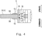
Fig. 4 is a sectional view taken along a line IV-IV ofFig. 2 , in which the illustration of coils is omitted and connecting wires are illustrated (first exemplary embodiment); -
Fig. 5 is an enlarged view of a portion "C" shown inFig. 2 , in which coils are illustrated and the illustration of connecting wires is omitted (first exemplary embodiment); -
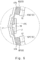
Fig. 6 is an enlarged view of the portion "C" shown inFig. 2 , in which coils and connecting wires are illustrated (first exemplary embodiment); -
Fig. 7 is an enlarged view of a portion "B" shown inFig. 1 , in which the illustration of coils, connecting wires, and teeth located on the front side is omitted (first exemplary embodiment); -
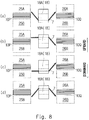
Fig. 8 is a schematic diagram for explaining wiring of connecting wires (first exemplary embodiment); -
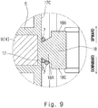
Fig. 9 is a sectional enlarged view of a guide hook (first modified example); -
Fig. 10 is a perspective view of a resolver stator, in which coils and connecting wires are illustrated (second exemplary embodiment); and -
Fig. 11 is a diagram corresponding toFig. 5 of Japanese Unexamined Patent Application Publication No.2012-50194 - A first exemplary embodiment will be described below with reference to
Figs. 1 to 8 . As shown inFigs. 1 and2 , aresolver 1 includes aresolver stator 2 and aresolver rotor 3 that is fixed to a shaft of, for example, a motor or an internal combustion (not shown). Theresolver 1 is used to measure the angle and rotational speed of the shaft. Theresolver 1 is a so-called inner rotor type having a structure in which theresolver rotor 3 is disposed inward in the radial direction of theresolver stator 2. The resolverstator 2 has a rotation axis 2C. - Hereinafter, as a general rule, the term "radial direction" refers to the radial direction of the
resolver stator 2 and the term "circumferential direction" refers to the circumferential direction of theresolver stator 2. Theresolver stator 2 has an upward direction (first axial direction) parallel to the rotation axis 2C, and a downward direction (second axial direction) opposite to the upward direction. - As shown in
Figs. 1 to 3 , theresolver stator 2 includes astator core 4, aninsulator 5, a plurality ofcoils 6, a plurality of connectingwires 7, and anexternal connecting portion 8. - As shown in
Fig. 3 , in the first exemplary embodiment, thestator core 4 is a laminated body of electromagnetic steel sheets. Thestator core 4 includes ayoke 9 having an annular shape, and a plurality ofteeth 10 projecting inward in the radial direction from theyoke 9. Each of theteeth 10 includes a tooth winding portion 11 and a teethdistal end 12. The tooth winding portion 11 extends from theyoke 9 toward the rotation axis 2C. The tooth winding portion 11 is elongated along the radial direction. The teethdistal end 12 is disposed at a distal end of the tooth winding portion 11 and extends along the circumferential direction. - Each
coil 6 is wound around the tooth winding portion 11 of each of theteeth 10. Thecoils 6 may include only coils for excitation, may include only coils for detection, or may include coils for excitation and coils for detection. The number of turns of eachcoil 6 is adjusted as appropriate so that a generated induced voltage is sinusodially distributed. In the first exemplary embodiment, the number of turns of eachcoil 6 is not particularly limited. - The connecting
wires 7 electrically connect the plurality ofcoils 6 to each other. Specifically, some connectingwires 7 electrically connect a plurality of excitation coils included in the plurality ofcoils 6 to each other, and other connectingwires 7 electrically connect a plurality of detection coils included in the plurality ofcoils 6 to each other. The plurality ofcoils 6 include afirst coil 6P (first coil) and asecond coil 6Q (second coil) which are adjacent to each other in the circumferential direction. Each connectingwire 7 extends, for example, from afirst tooth 10P (first tooth), which is thetooth 10 corresponding to thefirst coil 6P, toward asecond tooth 10Q (second tooth) which is thetooth 10 corresponding to thesecond coil 6Q. In other words, each connectingwire 7 extends, for example, from thefirst tooth 10P (first tooth), which is thetooth 10 at which thefirst coil 6P is disposed, toward thesecond tooth 10Q (second tooth) which is thetooth 10 at which thesecond coil 6Q is disposed. - The
insulator 5 is made of insulating resin and is fixed to thestator core 4 by, for example, insert molding. Theinsulator 5 is provided mainly for preventing the plurality ofcoils 6 and the plurality of connectingwires 7 from being brought into direct contact with thestator core 4. As shown inFigs. 2 and4 , theinsulator 5 includes a core uppersurface cover portion 15, a core lowersurface cover portion 16, a core inner peripheralsurface cover portion 17, a plurality ofguide hooks 18, and aperipheral wall 19. - As shown in
Fig. 4 , theyoke 9 of thestator core 4 has a yokeupper surface 9A that faces upward, a yokelower surface 9B that faces downward, and an innerperipheral surface 9C. The core uppersurface cover portion 15 is disposed on the yokeupper surface 9A so as to cover the yokeupper surface 9A. The core lowersurface cover portion 16 is disposed on the yokelower surface 9B so as to cover the yokelower surface 9B. The core inner peripheralsurface cover portion 17 is disposed on the innerperipheral surface 9C so as to cover the innerperipheral surface 9C. Accordingly, the core uppersurface cover portion 15, the core lowersurface cover portion 16, and the core inner peripheralsurface cover portion 17 form a U-shape in cross section. - As shown in
Fig. 5 , the core inner peripheralsurface cover portion 17 includes a firstflat surface 17A (first inner surface), a secondflat surface 17B (second inner surface), and arecess 17C. The firstflat surface 17A is a flat surface that is located outside of thefirst coil 6P in the radial direction and faces thefirst coil 6P in the radial direction. The secondflat surface 17B is a flat surface that is located outside of thesecond coil 6Q in the radial direction and faces thesecond coil 6Q in the radial direction. Therecess 17C is disposed between the firstflat surface 17A and the secondflat surface 17B. Therecess 17C is recessed outward in the radial direction. Specifically, a plane virtually extending from the firstflat surface 17A when the firstflat surface 17A and the secondflat surface 17B are virtually extended until the firstflat surface 17A and the secondflat surface 17B intersect with each other is defined as a firstvirtual plane 20A (first virtual plane). Similarly, a plane virtually extending from the secondflat surface 17B when the firstflat surface 17A and the secondflat surface 17B are virtually extended until the firstflat surface 17A and the secondflat surface 17B intersect with each other is defined as a secondvirtual plane 20B (second virtual plane). Therecess 17C is recessed outward in the radial direction relative to the firstvirtual plane 20A and the secondvirtual plane 20B. In the first exemplary embodiment, aninside surface 21 of therecess 17C includes aflat surface 21A that is parallel to the firstvirtual plane 20A, and aflat surface 21B that is parallel to the secondvirtual plane 20B. Theinside surface 21 of therecess 17C has a V-shape in plan view. However, theinside surface 21 of therecess 17C may instead be a curved surface that is curved so as to be convex outward in the radial direction, or may have other shapes. Note that the term "plan view" means a view along the rotation axis 2C. -
Fig. 6 illustrates a state where eachguide hook 18 guides the connectingwire 7. Note that inFig. 6 , for ease of explanation, only one connectingwire 7 extending from thefirst tooth 10P toward thesecond tooth 10Q is illustrated, and the illustration of the other connectingwires 7 is omitted. As shown inFig. 6 , eachguide hook 18 is disposed between two coils 6 (thefirst coil 6P and thesecond coil 6Q) that are adjacent to each other in the circumferential direction. In other words, eachguide hook 18 is disposed between two teeth 10 (thefirst tooth 10P and thesecond tooth 10Q) that are adjacent to each other in the circumferential direction. Eachguide hook 18 is disposed at thecorresponding recess 17C of the core inner peripheralsurface cover portion 17. In the first exemplary embodiment, only oneguide hook 18 is disposed at eachrecess 17C of the core inner peripheralsurface cover portion 17. Eachguide hook 18 is disposed in such a manner that theguide hook 18 is visible from the rotation axis 2C of theresolver stator 2. When eachguide hook 18 is viewed from the rotation axis 2C of theresolver stator 2, theguide hook 18 is disposed at a distance, in the circumferential direction, from the teeth distal ends 12 of the two teeth 10 (thefirst tooth 10P and thesecond tooth 10Q) that are adjacent to each other in the circumferential direction. Eachguide hook 18 guides the corresponding connectingwire 7 extending from thefirst tooth 10P toward thesecond tooth 10Q. As shown inFig. 7 , eachguide hook 18 includes an inward projectingportion 18A, a first projectingportion 18B, and a second projectingportion 18C. The inward projectingportion 18A projects inward in the radial direction from theinside surface 21 of therecess 17C of the core inner peripheralsurface cover portion 17. The first projectingportion 18B projects upward from the distal end of the inward projectingportion 18A. The second projectingportion 18C projects downward from the distal end of the inward projectingportion 18A. The first projectingportion 18B and the second projectingportion 18C are disposed at a distance from theinside surface 21 of therecess 17C of the core inner peripheralsurface cover portion 17 in the radial direction. The inward projectingportion 18A has a thin-plate shape, and the thickness direction of the inward projectingportion 18A is parallel to the rotation axis 2C. The first projectingportion 18B and the second projectingportion 18C each have a thin-plate shape, and the thickness direction of the first projectingportion 18B and the second projectingportion 18C is parallel to the radial direction. Eachguide hook 18 further includes afirst protrusion 18D and a second protrusion (not shown). Thefirst protrusion 18D projects outward in the radial direction from the center in the circumferential direction of the first projectingportion 18B. The second protrusion projects outward in the radial direction from the center in the circumferential direction of the second projectingportion 18C. As shown inFig. 5 , thefirst protrusion 18D of eachguide hook 18 may be located inward in the radial direction relative to the firstvirtual plane 20A, or may project outward in the radial direction across the firstvirtual plane 20A and the secondvirtual plane 20B. The same holds true for the second protrusion of eachguide hook 18. - As shown in
Fig. 4 , theperipheral wall 19 projects upward and downward from the core inner peripheralsurface cover portion 17. As shown inFig. 2 , theperipheral wall 19 is formed so as to have an annular shape. The presence of theperipheral wall 19 prevents eachcoil 6 from being deformed outward in the radial direction. - The external connecting
portion 8 is a portion that holds an end of each of the plurality of connectingwires 7 so as to receive an excitation signal supplied from an external device, and output detection signals generated by theresolver stator 2 to the external device. The external connectingportion 8 includes a plurality of terminals and a terminal holding portion. An end of each of the plurality of connectingwire 7 is electrically connected to a corresponding one of each of the plurality of terminals. The terminal holding portion holds the plurality of terminals by insert molding. The terminal holding portion is formed integrally with theinsulator 5. The terminal holding portion may instead be formed separately from theinsulator 5. - Next, the arrangement of the connecting
wires 7 will be described in detail with reference toFigs. 6 and8 . InFig. 8 , a space formed above thefirst tooth 10P is defined as a firstupper space 25A, and a space formed below thefirst tooth 10P is defined as a firstlower space 25B. Similarly, a space formed above thesecond tooth 10Q is defined as a secondupper space 26A, and a space formed below thesecond tooth 10Q is defined as a secondlower space 26B. InFig. 8 , (a) illustrates a case where the connectingwire 7 extends from the firstupper space 25A toward the secondupper space 26A; (b) illustrates a case where the connectingwire 7 extends from the firstupper space 25A toward the secondlower space 26B; (c) illustrates a case where the connectingwire 7 extends from the firstlower space 25B toward the secondupper space 26A; and (d) illustrates a case where the connectingwire 7 extends from the firstlower space 25B toward the secondlower space 26B. In the case (a) where the connectingwire 7 extends from the firstupper space 25A toward the secondupper space 26A, the connectingwire 7 is guided to theguide hook 18 so that the connectingwire 7 passes below the inward projectingportion 18A of theguide hook 18, with the result that the connectingwire 7 is curved so as to be convex downward. Similarly, in the case (b) where the connectingwire 7 extends from the firstupper space 25A toward the secondlower space 26B, the connectingwire 7 is guided to theguide hook 18 so that the connectingwire 7 passes above the inward projectingportion 18A of theguide hook 18, with the result that the connectingwire 7 is curved so as to be convex upward. Similarly, in the case (c) where the connectingwire 7 extends from the firstlower space 25B toward the secondupper space 26A, the connectingwire 7 is guided to theguide hook 18 so that the connectingwire 7 passes below the inward projectingportion 18A of theguide hook 18, with the result that the connectingwire 7 is curved so as to be convex downward. Similarly, in the case (d) where the connectingwire 7 extends from the firstlower space 25B toward the secondlower space 26B, the connectingwire 7 is guided to theguide hook 18 so that the connectingwire 7 passes above the inward projectingportion 18A of the guide hook 18 (also seeFig. 6 ), with the result that the connectingwire 7 is curved so as to be convex upward. In any of the above cases, when the connectingwire 7 passes above the inward projectingportion 18A of theguide hook 18, the connectingwire 7 passes between theinside surface 21 of therecess 17C and the first projectingportion 18B of theguide hook 18 shown inFig. 7 . At this time, the connectingwire 7 faces the first projectingportion 18B of theguide hook 18 in the radial direction (also seeFig. 4 ). Similarly, in any one of the above cases, when the connectingwire 7 passes below the inward projectingportion 18A of theguide hook 18, the connectingwire 7 passes between theinside surface 21 of therecess 17C and the second projectingportion 18C of theguide hook 18. At this time, the connectingwire 7 faces the second projectingportion 18C of theguide hook 18 in the radial direction (also seeFig. 4 ). Further, since theguide hook 18 is disposed at therecess 17C as shown inFig. 6 , when disposing the connectingwire 7 from thefirst tooth 10P toward thesecond tooth 10Q, the connectingwire 7 which has passed through theguide hook 18 can be brought closer to the secondflat surface 17B. This structure makes it possible to start winding thesecond coil 6Q from the root of thesecond tooth 10Q. - The first exemplary embodiment described above has the following features.
- The
resolver stator 2 includes: thestator core 4 including theyoke 9 having an annular shape and the plurality ofteeth 10 projecting inward in the radial direction from theyoke 9; theinsulator 5 that covers the inner peripheral surface of theyoke 9; the plurality ofcoils 6 to be wound around the plurality ofteeth 10, respectively; the connectingwires 7 that electrically connect the plurality ofcoils 6 to each other; and the guide hooks 18 that guide the connectingwires 7. The plurality ofcoils 6 include thefirst coil 6P and thesecond coil 6Q that are adjacent to each other in the circumferential direction. At least a part of each of the connectingwires 7 extends from thefirst tooth 10P corresponding to thefirst coil 6P toward thesecond tooth 10Q corresponding to thesecond coil 6Q, and is hooked to thecorresponding guide hook 18 so as to be curved in a convex shape projecting outward in the radial direction. Theinsulator 5 includes: the firstflat surface 17A (first inner surface) that is located outside of thefirst coil 6P in the radial direction and faces thefirst coil 6P in the radial direction; the secondflat surface 17B (second inner surface) that is located outside of thesecond coil 6Q in the radial direction and faces thesecond coil 6Q in the radial direction; and therecess 17C that is recessed outward in the radial direction relative to the firstvirtual plane 20A (first virtual plane) and the secondvirtual plane 20B (second virtual plane), the firstvirtual plane 20A and the secondvirtual plane 20B being defined by virtually extending the firstflat surface 17A and the secondflat surface 17B until the firstflat surface 17A and the secondflat surface 17B intersect with each other. The firstvirtual plane 20A virtually extends from the firstflat surface 17A, and the secondvirtual plane 20B virtually extends from the secondflat surface 17B. Theguide hook 18 is disposed at thecorresponding recess 17C. According to the above structure, unlike in the case where therecess 17C is not provided, when winding each connectingwire 7 from thefirst tooth 10P corresponding to thefirst coil 6P toward thesecond tooth 10Q corresponding to thesecond coil 6Q, the connectingwire 7 which has passed through theguide hook 18 can be brought closer to the secondflat surface 17B. This structure makes it possible to start winding thesecond coil 6Q from the root of thesecond tooth 10Q. - The
resolver stator 2 has the upward direction (first axial direction) parallel to the rotation axis 2C of theresolver stator 2, and the downward direction (second axial direction) opposite to the upward direction. Eachguide hook 18 includes: the inward projectingportion 18A projecting inward in the radial direction from theinside surface 21 of therecess 17C; the first projectingportion 18B projecting upward from the inward projectingportion 18A; and the second projectingportion 18C projecting downward from the inward projectingportion 18A. According to the above structure, the guide hooks 18 can guide each connectingwire 7 in any one of the following cases, without any problem. That is, (1) a case where the connectingwire 7 extends from the firstupper space 25A toward the secondupper space 26A; (2) a case where the connectingwire 7 extends from the firstupper space 25A toward the secondlower space 26B; (3) a case where the connectingwire 7 extends from the firstlower space 25B toward the secondupper space 26A; and (4) a case where the connectingwire 7 extends from the firstlower space 25B toward the secondlower space 26B. - Each
guide hook 18 is disposed so as to be visible from the rotation axis 2C of theresolver stator 2. According to the above structure, a variation in the posture of a winding nozzle can be suppressed when each connectingwire 7 is hooked to thecorresponding guide hook 18, unlike in the case where eachguide hook 18 is disposed at a location where theguide hook 18 is not visible from the rotation axis 2C of theresolver stator 2. Thus, a time required for winding can be reduced. - As shown in
Fig. 9 , the inward projectingportion 18A may be tapered outward in the radial direction. Specifically, the inward projectingportion 18A may be formed in such a manner that the thickness of the inward projectingportion 18A gradually decreases toward the outside in the radial direction. According to the above structure, when a tension is applied to the connectingwire 7 that is hooked to theguide hook 18, the connectingwire 7 automatically moves outward in the radial direction along an inclination of the inward projectingportion 18A. This structure makes it possible to more reliably start winding thesecond coil 6Q from the root of thesecond tooth 10Q. The thickness of the inward projectingportion 18A refers to the dimension of the inward projectingportion 18A in the axial direction of theresolver stator 2. - Note that in the first exemplary embodiment described above, the number of the
guide hook 18 may be one, and the number of the connectingwire 7 may be one. - A second exemplary embodiment will be described below with reference to
Fig. 10 . Differences between the second exemplary embodiment and the first exemplary embodiment will be mainly described below, and repeated explanations are omitted. - In the first exemplary embodiment, as shown in
Fig. 3 , only oneguide hook 18 is disposed between two coils 6 (thefirst coil 6P and thesecond coil 6Q) that are adjacent to each other in the circumferential direction. On the other hand, in the second embodiment, as shown inFig. 10 , four guide hooks 18 are disposed between two coils 6 (thefirst coil 6P and thesecond coil 6Q) that are adjacent to each other in the circumferential direction. The four guide hooks 18 include two upper guide hooks 30 (first guide hook) and two lower guide hooks 31 (second guide hook). The two upper guide hooks 30 are disposed above the two lower guide hooks 31. Eachupper guide hook 30 projects inward in the radial direction from theinside surface 21 of therecess 17C and then projects downward. The two upper guide hooks 30 are disposed in the circumferential direction in such a manner that they are slightly apart from each other. Eachlower guide hook 31 projects inward in the radial direction from theinside surface 21 of therecess 17C and then projects upward. The two lower guide hooks 31 are disposed in the circumferential direction in such a manner that they are slightly apart from each other. The two upper guide hooks 30 and the two lower guide hooks 31 are disposed in such a manner that they do not overlap each other in the axial direction of theresolver stator 2, in consideration of demolding during injection molding. -
Fig. 10 illustrates three connectingwires 7 extending from thefirst tooth 10P toward thesecond tooth 10Q. As shown inFig. 10 , the connectingwires 7 each pass below the two upper guide hooks 30 and pass above the two lower guide hooks 31. - Which
guide hook 18 is used to guide the connectingwires 7 is determined depending on the arrangement of the four guide hooks 18, the height dimensions of theteeth 10, and the like. Specific examples thereof are shown below. - (1) A case where the connecting
wire 7 extends from the firstupper space 25A toward the secondupper space 26A
In this case, the connectingwire 7 is guided by the two upper guide hooks 30. - (2) A case where the connecting
wire 7 extends from the firstupper space 25A toward the secondlower space 26B
In this case, the connectingwire 7 is guided by at least one or both of theupper guide hook 30 that is located closer to thefirst tooth 10P than the other one of the two upper guide hooks 30, and thelower guide hook 31 that is located closer to thesecond tooth 10Q than the other one of the two lower guide hooks 31. - (3) A case where the connecting
wire 7 extends from the firstlower space 25B toward the secondupper space 26A
In this case, the connectingwire 7 is guided by at least one or both of thelower guide hook 31 that is located closer to thefirst tooth 10P than the other one of the two lower guide hooks 31, and theupper guide hook 30 that is located closer to thesecond tooth 10Q than the other one of the two upper guide hooks 30. - (4) A case where the connecting
wire 7 extends from the firstlower space 25B toward the secondlower space 26B - In this case, the connecting
wire 7 is guided by the two lower guide hooks 31. - The second exemplary embodiment described above has the following features.
- The
resolver stator 2 includes the plurality of guide hooks 18. The plurality of guide hooks 18 include the upper guide hooks 30 (first guide hook) and the lower guide hooks 31 (second guide hook). Eachupper guide hook 30 is disposed between thefirst coil 6P and thesecond coil 6Q and projects inward in the radial direction from theinside surface 21 of therecess 17C and projects downward. Eachlower guide hook 31 is disposed between thefirst coil 6P and thesecond coil 6Q and projects inward in the radial direction from theinside surface 21 of therecess 17C and projects upward. According to the above structure, the connectingwires 7 can be guided without any problem in any one of the following cases. That is, a case (1) where the connectingwire 7 extends from the firstupper space 25A toward the secondupper space 26A; a case (2) where the connectingwire 7 extends from the firstupper space 25A toward the secondlower space 26B; a case (3) where the connectingwire 7 extends from the firstlower space 25B toward the secondupper space 26A; and a case (4) where the connectingwire 7 extends from the firstlower space 25B toward the secondlower space 26B. - The plurality of guide hooks 18 include two upper guide hooks 30. The two upper guide hooks 30 are disposed at a distance from each other in the circumferential direction. The plurality of guide hooks 18 include two lower guide hooks 31. The two lower guide hooks 31 are disposed at a distance from each other in the circumferential direction. According to the above structure, the guide hooks 18 can guide the corresponding connecting
wire 7 more reliably in any one of the following cases. That is, a case (1) where the connectingwire 7 extends from the firstupper space 25A toward the secondupper space 26A; a case (2) where the connectingwire 7 extends from the firstupper space 25A toward the secondlower space 26B; a case (3) where the connectingwire 7 extends from the firstlower space 25B toward the secondupper space 26A; and a case (4) where the connectingwire 7 extends from the firstlower space 25B toward the secondlower space 26B. - Note that in the second exemplary embodiment described above, the number of the guide hooks 18 is four, but instead may be five or more. The number of the upper guide hooks 30 is two, but instead may be one or three or more. The number of the lower guide hooks 31 is two, but instead may be one or three or more.
- In each of the exemplary embodiments described above, the
insulator 5 includes the core uppersurface cover portion 15, the core lowersurface cover portion 16, and the core inner peripheralsurface cover portion 17. Alternatively, the core uppersurface cover portion 15 and the core lowersurface cover portion 16 may be omitted. - Further, each connecting
wire 7 may electrically connect twocoils 6 adjacent to each other in the circumferential direction, or may electrically connect two coils that are not adjacent to each other in the circumferential direction. Twocoils 6 to be electrically connected by each connectingwire 7 are determined depending on how to wind the excitation coils and detection coils around theteeth 10, or which one of one-phase excitation two-phase detection, two-phase excitation one-phase detection, and two-phase excitation two-phase detection is adopted by theresolver stator 2. - The first
flat surface 17A and the secondflat surface 17B are flat surfaces, but instead may be curved surfaces. - From the invention thus described, it will be obvious that the embodiments of the invention may be varied in many ways. Such variations are not to be regarded as a departure from the spirit and scope of the invention, and all such modifications as would be obvious to one skilled in the art are intended for inclusion within the scope of the following claims.
Claims (4)
- A resolver stator comprising:a stator core including a yoke having an annular shape, and a plurality of teeth projecting inward in a radial direction from the yoke;an insulator that covers an inner peripheral surface of the yoke;a plurality of coils to be wound around the plurality of teeth, respectively;a connecting wire that electrically connects the plurality of coils to each other; anda guide hook that guides the connecting wire, whereinthe plurality of coils include a first coil and a second coil, the first coil and the second coil being adjacent to each other in a circumferential direction,
at least a part of the connecting wire extends from the tooth corresponding to the first coil toward the tooth corresponding to the second coil and is hooked to the guide hook so as to be curved in a convex shape projecting outward in the radial direction,
the insulator includes:a first inner surface that is located outside of the first coil in the radial direction and faces the first coil in the radial direction;a second inner surface that is located outside of the second coil in the radial direction and faces the second coil in the radial direction; anda recess that is recessed outward in the radial direction relative to a first virtual plane and a second virtual plane, the first virtual plane and the second virtual plane being defined by virtually extending the first inner surface and the second inner surface until the first inner surface and the second inner surface intersect with each other, the first virtual plane virtually extending from the first inner surface, the second virtual plane virtually extending from the second inner surface, andthe guide hook is disposed at the recess. - The resolver stator according to Claim 1, wherein
the resolver stator has a first axial direction parallel to a rotation axis of the resolver stator, and a second axial direction opposite to the first axial direction,
the guide hook includes:an inward projecting portion projecting inward in the radial direction from an inside surface of the recess;a first projecting portion projecting in the first axial direction from the inward projecting portion; anda second projecting portion projecting in the second axial direction from the inward projecting portion. - The resolver stator according to Claim 1, wherein
the resolver stator has a first axial direction parallel to a rotation axis of the resolver stator, and a second axial direction opposite to the first axial direction,
the resolver stator includes a plurality of the guide hooks,
the plurality of guide hooks include:a first guide hook that is disposed between the first coil and the second coil and projects inward in the radial direction from an inside surface of the recess and in the second axial direction; anda second guide hook that is disposed between the first coil and the second coil and projects inward in the radial direction from the inside surface of the recess and in the first axial direction. - The resolver stator according to Claim 3, wherein
the plurality of guide hooks include a plurality of the first guide hooks,
the plurality of first guide hooks are disposed at a distance from each other in the circumferential direction,
the plurality of guide hooks include a plurality of the second guide hooks, and
the plurality of second guide hooks are disposed at a distance from each other in the circumferential direction.
Applications Claiming Priority (1)
| Application Number | Priority Date | Filing Date | Title |
|---|---|---|---|
| JP2016028845A JP6647908B2 (en) | 2016-02-18 | 2016-02-18 | Resolver stator |
Publications (2)
| Publication Number | Publication Date |
|---|---|
| EP3208574A1 true EP3208574A1 (en) | 2017-08-23 |
| EP3208574B1 EP3208574B1 (en) | 2018-09-12 |
Family
ID=57680099
Family Applications (1)
| Application Number | Title | Priority Date | Filing Date |
|---|---|---|---|
| EP16206165.9A Not-in-force EP3208574B1 (en) | 2016-02-18 | 2016-12-22 | Resolver stator |
Country Status (3)
| Country | Link |
|---|---|
| EP (1) | EP3208574B1 (en) |
| JP (1) | JP6647908B2 (en) |
| CN (1) | CN107093931B (en) |
Families Citing this family (4)
| Publication number | Priority date | Publication date | Assignee | Title |
|---|---|---|---|---|
| EP3687043B1 (en) * | 2017-09-20 | 2024-03-13 | Panasonic Intellectual Property Management Co., Ltd. | Insulator, and stator and motor comprising same |
| JP6948274B2 (en) * | 2018-02-15 | 2021-10-13 | 東芝ライフスタイル株式会社 | Electric blower and vacuum cleaner |
| KR102608163B1 (en) * | 2018-08-21 | 2023-11-30 | 엘지이노텍 주식회사 | Stator and Motor having the same |
| JP7204706B2 (en) * | 2020-06-02 | 2023-01-16 | 三菱電機株式会社 | Stator, motor and blower |
Citations (4)
| Publication number | Priority date | Publication date | Assignee | Title |
|---|---|---|---|---|
| EP1276208A2 (en) * | 2001-07-11 | 2003-01-15 | Kabushiki Kaisha Moric | Stator coil structure for revolving field electrical machine and method of manufacturing same |
| US20060186753A1 (en) * | 2005-02-21 | 2006-08-24 | Samsung Electro-Mechanics Co., Ltd. | Stator and electric motor having the same |
| US20070040467A1 (en) * | 2005-08-17 | 2007-02-22 | Minebea Co., Ltd. | Stator arrangement for an electric machine and a method for manufacturing the stator arrangement |
| US7739788B1 (en) * | 2004-12-02 | 2010-06-22 | Maxtor Corporation | Support structure with integral retainer tabs for use in spindle motor wire routing |
Family Cites Families (9)
| Publication number | Priority date | Publication date | Assignee | Title |
|---|---|---|---|---|
| CA1071680A (en) * | 1976-06-16 | 1980-02-12 | Itw Fastex Italia S.P.A. | Insulating assembly for stator slots of electrical motors |
| JP2002325385A (en) * | 2001-02-22 | 2002-11-08 | Moric Co Ltd | Stator structure of rotating field type electric equipment |
| JP4594026B2 (en) * | 2004-10-07 | 2010-12-08 | 多摩川精機株式会社 | Resolver external conductor fixing structure |
| JP2008187787A (en) * | 2007-01-29 | 2008-08-14 | Nippon Densan Corp | Resolver and motor |
| JP2012050194A (en) * | 2010-08-25 | 2012-03-08 | Panasonic Electric Works Co Ltd | Motor, pump, and pump drive apparatus |
| JP2012165563A (en) * | 2011-02-07 | 2012-08-30 | Hitachi Industrial Equipment Systems Co Ltd | Winding machine and winding method |
| JP5872807B2 (en) * | 2011-07-12 | 2016-03-01 | ミネベア株式会社 | Connection structure of coil winding in motor and motor |
| JP6227315B2 (en) * | 2013-07-29 | 2017-11-08 | ミネベアミツミ株式会社 | VR-type resolver stator structure |
| JP5872007B1 (en) * | 2014-09-19 | 2016-03-01 | 日本航空電子工業株式会社 | Resolver stator |
-
2016
- 2016-02-18 JP JP2016028845A patent/JP6647908B2/en not_active Expired - Fee Related
- 2016-12-22 EP EP16206165.9A patent/EP3208574B1/en not_active Not-in-force
-
2017
- 2017-01-19 CN CN201710038261.6A patent/CN107093931B/en not_active Expired - Fee Related
Patent Citations (4)
| Publication number | Priority date | Publication date | Assignee | Title |
|---|---|---|---|---|
| EP1276208A2 (en) * | 2001-07-11 | 2003-01-15 | Kabushiki Kaisha Moric | Stator coil structure for revolving field electrical machine and method of manufacturing same |
| US7739788B1 (en) * | 2004-12-02 | 2010-06-22 | Maxtor Corporation | Support structure with integral retainer tabs for use in spindle motor wire routing |
| US20060186753A1 (en) * | 2005-02-21 | 2006-08-24 | Samsung Electro-Mechanics Co., Ltd. | Stator and electric motor having the same |
| US20070040467A1 (en) * | 2005-08-17 | 2007-02-22 | Minebea Co., Ltd. | Stator arrangement for an electric machine and a method for manufacturing the stator arrangement |
Also Published As
| Publication number | Publication date |
|---|---|
| CN107093931B (en) | 2020-01-21 |
| CN107093931A (en) | 2017-08-25 |
| EP3208574B1 (en) | 2018-09-12 |
| JP6647908B2 (en) | 2020-02-14 |
| JP2017147882A (en) | 2017-08-24 |
Similar Documents
| Publication | Publication Date | Title |
|---|---|---|
| EP3208920B1 (en) | Resolver stator | |
| EP3208574B1 (en) | Resolver stator | |
| EP3197021B1 (en) | Resolver stator | |
| EP2833521A1 (en) | Stator | |
| KR101967607B1 (en) | Electronically commutated direct-current motor | |
| JP2014014196A (en) | Armature, insulator, and motor | |
| JP2005057931A (en) | Stator | |
| EP2833520A1 (en) | Stator | |
| CN107078565A (en) | Stator for electric rotating machine | |
| JPWO2015093157A1 (en) | Rotating electric machine | |
| CN113196621A (en) | Electric machine | |
| EP3531539A1 (en) | Resolver stator | |
| JP5452177B2 (en) | Rotating electric machine | |
| JP6221064B2 (en) | Electric motor | |
| US10566867B2 (en) | Stator and method of manufacturing stator | |
| JP5907650B2 (en) | Stator and winding method of stator | |
| EP3052894B1 (en) | Resolver | |
| JP2018133989A (en) | Stator structure and resolver | |
| EP2226918A2 (en) | Stator for rotary electric machine | |
| JP6360544B2 (en) | Resolver stator | |
| CN111431314A (en) | Motor with a stator having a stator core |
Legal Events
| Date | Code | Title | Description |
|---|---|---|---|
| PUAI | Public reference made under article 153(3) epc to a published international application that has entered the european phase |
Free format text: ORIGINAL CODE: 0009012 |
|
| 17P | Request for examination filed |
Effective date: 20161222 |
|
| AK | Designated contracting states |
Kind code of ref document: A1 Designated state(s): AL AT BE BG CH CY CZ DE DK EE ES FI FR GB GR HR HU IE IS IT LI LT LU LV MC MK MT NL NO PL PT RO RS SE SI SK SM TR |
|
| AX | Request for extension of the european patent |
Extension state: BA ME |
|
| GRAP | Despatch of communication of intention to grant a patent |
Free format text: ORIGINAL CODE: EPIDOSNIGR1 |
|
| INTG | Intention to grant announced |
Effective date: 20180531 |
|
| GRAS | Grant fee paid |
Free format text: ORIGINAL CODE: EPIDOSNIGR3 |
|
| GRAA | (expected) grant |
Free format text: ORIGINAL CODE: 0009210 |
|
| AK | Designated contracting states |
Kind code of ref document: B1 Designated state(s): AL AT BE BG CH CY CZ DE DK EE ES FI FR GB GR HR HU IE IS IT LI LT LU LV MC MK MT NL NO PL PT RO RS SE SI SK SM TR |
|
| REG | Reference to a national code |
Ref country code: GB Ref legal event code: FG4D |
|
| REG | Reference to a national code |
Ref country code: CH Ref legal event code: EP |
|
| REG | Reference to a national code |
Ref country code: IE Ref legal event code: FG4D |
|
| REG | Reference to a national code |
Ref country code: DE Ref legal event code: R096 Ref document number: 602016005563 Country of ref document: DE |
|
| REG | Reference to a national code |
Ref country code: AT Ref legal event code: REF Ref document number: 1041147 Country of ref document: AT Kind code of ref document: T Effective date: 20181015 |
|
| REG | Reference to a national code |
Ref country code: NL Ref legal event code: MP Effective date: 20180912 |
|
| REG | Reference to a national code |
Ref country code: LT Ref legal event code: MG4D |
|
| PG25 | Lapsed in a contracting state [announced via postgrant information from national office to epo] |
Ref country code: FI Free format text: LAPSE BECAUSE OF FAILURE TO SUBMIT A TRANSLATION OF THE DESCRIPTION OR TO PAY THE FEE WITHIN THE PRESCRIBED TIME-LIMIT Effective date: 20180912 Ref country code: SE Free format text: LAPSE BECAUSE OF FAILURE TO SUBMIT A TRANSLATION OF THE DESCRIPTION OR TO PAY THE FEE WITHIN THE PRESCRIBED TIME-LIMIT Effective date: 20180912 Ref country code: LT Free format text: LAPSE BECAUSE OF FAILURE TO SUBMIT A TRANSLATION OF THE DESCRIPTION OR TO PAY THE FEE WITHIN THE PRESCRIBED TIME-LIMIT Effective date: 20180912 Ref country code: GR Free format text: LAPSE BECAUSE OF FAILURE TO SUBMIT A TRANSLATION OF THE DESCRIPTION OR TO PAY THE FEE WITHIN THE PRESCRIBED TIME-LIMIT Effective date: 20181213 Ref country code: RS Free format text: LAPSE BECAUSE OF FAILURE TO SUBMIT A TRANSLATION OF THE DESCRIPTION OR TO PAY THE FEE WITHIN THE PRESCRIBED TIME-LIMIT Effective date: 20180912 Ref country code: NO Free format text: LAPSE BECAUSE OF FAILURE TO SUBMIT A TRANSLATION OF THE DESCRIPTION OR TO PAY THE FEE WITHIN THE PRESCRIBED TIME-LIMIT Effective date: 20181212 Ref country code: BG Free format text: LAPSE BECAUSE OF FAILURE TO SUBMIT A TRANSLATION OF THE DESCRIPTION OR TO PAY THE FEE WITHIN THE PRESCRIBED TIME-LIMIT Effective date: 20181212 |
|
| PG25 | Lapsed in a contracting state [announced via postgrant information from national office to epo] |
Ref country code: AL Free format text: LAPSE BECAUSE OF FAILURE TO SUBMIT A TRANSLATION OF THE DESCRIPTION OR TO PAY THE FEE WITHIN THE PRESCRIBED TIME-LIMIT Effective date: 20180912 Ref country code: HR Free format text: LAPSE BECAUSE OF FAILURE TO SUBMIT A TRANSLATION OF THE DESCRIPTION OR TO PAY THE FEE WITHIN THE PRESCRIBED TIME-LIMIT Effective date: 20180912 Ref country code: LV Free format text: LAPSE BECAUSE OF FAILURE TO SUBMIT A TRANSLATION OF THE DESCRIPTION OR TO PAY THE FEE WITHIN THE PRESCRIBED TIME-LIMIT Effective date: 20180912 |
|
| REG | Reference to a national code |
Ref country code: AT Ref legal event code: MK05 Ref document number: 1041147 Country of ref document: AT Kind code of ref document: T Effective date: 20180912 |
|
| PG25 | Lapsed in a contracting state [announced via postgrant information from national office to epo] |
Ref country code: AT Free format text: LAPSE BECAUSE OF FAILURE TO SUBMIT A TRANSLATION OF THE DESCRIPTION OR TO PAY THE FEE WITHIN THE PRESCRIBED TIME-LIMIT Effective date: 20180912 Ref country code: NL Free format text: LAPSE BECAUSE OF FAILURE TO SUBMIT A TRANSLATION OF THE DESCRIPTION OR TO PAY THE FEE WITHIN THE PRESCRIBED TIME-LIMIT Effective date: 20180912 Ref country code: IS Free format text: LAPSE BECAUSE OF FAILURE TO SUBMIT A TRANSLATION OF THE DESCRIPTION OR TO PAY THE FEE WITHIN THE PRESCRIBED TIME-LIMIT Effective date: 20190112 Ref country code: PL Free format text: LAPSE BECAUSE OF FAILURE TO SUBMIT A TRANSLATION OF THE DESCRIPTION OR TO PAY THE FEE WITHIN THE PRESCRIBED TIME-LIMIT Effective date: 20180912 Ref country code: EE Free format text: LAPSE BECAUSE OF FAILURE TO SUBMIT A TRANSLATION OF THE DESCRIPTION OR TO PAY THE FEE WITHIN THE PRESCRIBED TIME-LIMIT Effective date: 20180912 Ref country code: CZ Free format text: LAPSE BECAUSE OF FAILURE TO SUBMIT A TRANSLATION OF THE DESCRIPTION OR TO PAY THE FEE WITHIN THE PRESCRIBED TIME-LIMIT Effective date: 20180912 Ref country code: RO Free format text: LAPSE BECAUSE OF FAILURE TO SUBMIT A TRANSLATION OF THE DESCRIPTION OR TO PAY THE FEE WITHIN THE PRESCRIBED TIME-LIMIT Effective date: 20180912 Ref country code: IT Free format text: LAPSE BECAUSE OF FAILURE TO SUBMIT A TRANSLATION OF THE DESCRIPTION OR TO PAY THE FEE WITHIN THE PRESCRIBED TIME-LIMIT Effective date: 20180912 |
|
| PG25 | Lapsed in a contracting state [announced via postgrant information from national office to epo] |
Ref country code: SM Free format text: LAPSE BECAUSE OF FAILURE TO SUBMIT A TRANSLATION OF THE DESCRIPTION OR TO PAY THE FEE WITHIN THE PRESCRIBED TIME-LIMIT Effective date: 20180912 Ref country code: PT Free format text: LAPSE BECAUSE OF FAILURE TO SUBMIT A TRANSLATION OF THE DESCRIPTION OR TO PAY THE FEE WITHIN THE PRESCRIBED TIME-LIMIT Effective date: 20190112 Ref country code: SK Free format text: LAPSE BECAUSE OF FAILURE TO SUBMIT A TRANSLATION OF THE DESCRIPTION OR TO PAY THE FEE WITHIN THE PRESCRIBED TIME-LIMIT Effective date: 20180912 |
|
| REG | Reference to a national code |
Ref country code: DE Ref legal event code: R097 Ref document number: 602016005563 Country of ref document: DE |
|
| PLBE | No opposition filed within time limit |
Free format text: ORIGINAL CODE: 0009261 |
|
| STAA | Information on the status of an ep patent application or granted ep patent |
Free format text: STATUS: NO OPPOSITION FILED WITHIN TIME LIMIT |
|
| PG25 | Lapsed in a contracting state [announced via postgrant information from national office to epo] |
Ref country code: DK Free format text: LAPSE BECAUSE OF FAILURE TO SUBMIT A TRANSLATION OF THE DESCRIPTION OR TO PAY THE FEE WITHIN THE PRESCRIBED TIME-LIMIT Effective date: 20180912 Ref country code: ES Free format text: LAPSE BECAUSE OF FAILURE TO SUBMIT A TRANSLATION OF THE DESCRIPTION OR TO PAY THE FEE WITHIN THE PRESCRIBED TIME-LIMIT Effective date: 20180912 |
|
| 26N | No opposition filed |
Effective date: 20190613 |
|
| PG25 | Lapsed in a contracting state [announced via postgrant information from national office to epo] |
Ref country code: SI Free format text: LAPSE BECAUSE OF FAILURE TO SUBMIT A TRANSLATION OF THE DESCRIPTION OR TO PAY THE FEE WITHIN THE PRESCRIBED TIME-LIMIT Effective date: 20180912 Ref country code: LU Free format text: LAPSE BECAUSE OF NON-PAYMENT OF DUE FEES Effective date: 20181222 Ref country code: MC Free format text: LAPSE BECAUSE OF FAILURE TO SUBMIT A TRANSLATION OF THE DESCRIPTION OR TO PAY THE FEE WITHIN THE PRESCRIBED TIME-LIMIT Effective date: 20180912 |
|
| REG | Reference to a national code |
Ref country code: IE Ref legal event code: MM4A |
|
| REG | Reference to a national code |
Ref country code: BE Ref legal event code: MM Effective date: 20181231 |
|
| PG25 | Lapsed in a contracting state [announced via postgrant information from national office to epo] |
Ref country code: IE Free format text: LAPSE BECAUSE OF NON-PAYMENT OF DUE FEES Effective date: 20181222 |
|
| PG25 | Lapsed in a contracting state [announced via postgrant information from national office to epo] |
Ref country code: BE Free format text: LAPSE BECAUSE OF NON-PAYMENT OF DUE FEES Effective date: 20181231 |
|
| PG25 | Lapsed in a contracting state [announced via postgrant information from national office to epo] |
Ref country code: MT Free format text: LAPSE BECAUSE OF NON-PAYMENT OF DUE FEES Effective date: 20181222 |
|
| PG25 | Lapsed in a contracting state [announced via postgrant information from national office to epo] |
Ref country code: TR Free format text: LAPSE BECAUSE OF FAILURE TO SUBMIT A TRANSLATION OF THE DESCRIPTION OR TO PAY THE FEE WITHIN THE PRESCRIBED TIME-LIMIT Effective date: 20180912 |
|
| PG25 | Lapsed in a contracting state [announced via postgrant information from national office to epo] |
Ref country code: MK Free format text: LAPSE BECAUSE OF NON-PAYMENT OF DUE FEES Effective date: 20180912 Ref country code: HU Free format text: LAPSE BECAUSE OF FAILURE TO SUBMIT A TRANSLATION OF THE DESCRIPTION OR TO PAY THE FEE WITHIN THE PRESCRIBED TIME-LIMIT; INVALID AB INITIO Effective date: 20161222 Ref country code: CY Free format text: LAPSE BECAUSE OF FAILURE TO SUBMIT A TRANSLATION OF THE DESCRIPTION OR TO PAY THE FEE WITHIN THE PRESCRIBED TIME-LIMIT Effective date: 20180912 |
|
| REG | Reference to a national code |
Ref country code: CH Ref legal event code: PL |
|
| PG25 | Lapsed in a contracting state [announced via postgrant information from national office to epo] |
Ref country code: LI Free format text: LAPSE BECAUSE OF NON-PAYMENT OF DUE FEES Effective date: 20191231 Ref country code: CH Free format text: LAPSE BECAUSE OF NON-PAYMENT OF DUE FEES Effective date: 20191231 |
|
| PGFP | Annual fee paid to national office [announced via postgrant information from national office to epo] |
Ref country code: GB Payment date: 20231102 Year of fee payment: 8 |
|
| PGFP | Annual fee paid to national office [announced via postgrant information from national office to epo] |
Ref country code: FR Payment date: 20231108 Year of fee payment: 8 Ref country code: DE Payment date: 20231031 Year of fee payment: 8 |
|
| REG | Reference to a national code |
Ref country code: DE Ref legal event code: R119 Ref document number: 602016005563 Country of ref document: DE |
|
| GBPC | Gb: european patent ceased through non-payment of renewal fee |
Effective date: 20241222 |
|
| PG25 | Lapsed in a contracting state [announced via postgrant information from national office to epo] |
Ref country code: DE Free format text: LAPSE BECAUSE OF NON-PAYMENT OF DUE FEES Effective date: 20250701 |
|
| PG25 | Lapsed in a contracting state [announced via postgrant information from national office to epo] |
Ref country code: GB Free format text: LAPSE BECAUSE OF NON-PAYMENT OF DUE FEES Effective date: 20241222 |
|
| PG25 | Lapsed in a contracting state [announced via postgrant information from national office to epo] |
Ref country code: FR Free format text: LAPSE BECAUSE OF NON-PAYMENT OF DUE FEES Effective date: 20241231 |