EP3208511B1 - Device for monitoring a monitored area of a driverless vehicle - Google Patents
Device for monitoring a monitored area of a driverless vehicle Download PDFInfo
- Publication number
- EP3208511B1 EP3208511B1 EP17156037.8A EP17156037A EP3208511B1 EP 3208511 B1 EP3208511 B1 EP 3208511B1 EP 17156037 A EP17156037 A EP 17156037A EP 3208511 B1 EP3208511 B1 EP 3208511B1
- Authority
- EP
- European Patent Office
- Prior art keywords
- sensors
- movement
- vehicle
- accordance
- detection
- Prior art date
- Legal status (The legal status is an assumption and is not a legal conclusion. Google has not performed a legal analysis and makes no representation as to the accuracy of the status listed.)
- Active
Links
- 238000012544 monitoring process Methods 0.000 title claims description 22
- 238000001514 detection method Methods 0.000 claims description 52
- 238000011156 evaluation Methods 0.000 claims description 14
- 230000001154 acute effect Effects 0.000 claims description 10
- 230000001681 protective effect Effects 0.000 description 29
- 238000000034 method Methods 0.000 description 8
- 238000011161 development Methods 0.000 description 6
- 230000000875 corresponding effect Effects 0.000 description 3
- 230000001419 dependent effect Effects 0.000 description 3
- 238000005259 measurement Methods 0.000 description 3
- 230000003068 static effect Effects 0.000 description 3
- 230000003247 decreasing effect Effects 0.000 description 2
- 231100001261 hazardous Toxicity 0.000 description 2
- 230000003287 optical effect Effects 0.000 description 2
- 230000035515 penetration Effects 0.000 description 2
- 238000012360 testing method Methods 0.000 description 2
- 241000183024 Populus tremula Species 0.000 description 1
- 230000003321 amplification Effects 0.000 description 1
- 238000013459 approach Methods 0.000 description 1
- 230000005540 biological transmission Effects 0.000 description 1
- 230000015556 catabolic process Effects 0.000 description 1
- 230000002596 correlated effect Effects 0.000 description 1
- 230000004069 differentiation Effects 0.000 description 1
- 230000000694 effects Effects 0.000 description 1
- 238000003199 nucleic acid amplification method Methods 0.000 description 1
- 230000001105 regulatory effect Effects 0.000 description 1
- 230000002441 reversible effect Effects 0.000 description 1
- 230000035945 sensitivity Effects 0.000 description 1
- 229910052710 silicon Inorganic materials 0.000 description 1
- 239000010703 silicon Substances 0.000 description 1
- 238000007619 statistical method Methods 0.000 description 1
- 238000010408 sweeping Methods 0.000 description 1
- 238000002366 time-of-flight method Methods 0.000 description 1
Images


Classifications
-
- G—PHYSICS
- G01—MEASURING; TESTING
- G01V—GEOPHYSICS; GRAVITATIONAL MEASUREMENTS; DETECTING MASSES OR OBJECTS; TAGS
- G01V8/00—Prospecting or detecting by optical means
- G01V8/10—Detecting, e.g. by using light barriers
- G01V8/20—Detecting, e.g. by using light barriers using multiple transmitters or receivers
-
- G—PHYSICS
- G01—MEASURING; TESTING
- G01D—MEASURING NOT SPECIALLY ADAPTED FOR A SPECIFIC VARIABLE; ARRANGEMENTS FOR MEASURING TWO OR MORE VARIABLES NOT COVERED IN A SINGLE OTHER SUBCLASS; TARIFF METERING APPARATUS; MEASURING OR TESTING NOT OTHERWISE PROVIDED FOR
- G01D5/00—Mechanical means for transferring the output of a sensing member; Means for converting the output of a sensing member to another variable where the form or nature of the sensing member does not constrain the means for converting; Transducers not specially adapted for a specific variable
- G01D5/26—Mechanical means for transferring the output of a sensing member; Means for converting the output of a sensing member to another variable where the form or nature of the sensing member does not constrain the means for converting; Transducers not specially adapted for a specific variable characterised by optical transfer means, i.e. using infrared, visible, or ultraviolet light
- G01D5/28—Mechanical means for transferring the output of a sensing member; Means for converting the output of a sensing member to another variable where the form or nature of the sensing member does not constrain the means for converting; Transducers not specially adapted for a specific variable characterised by optical transfer means, i.e. using infrared, visible, or ultraviolet light with deflection of beams of light, e.g. for direct optical indication
- G01D5/30—Mechanical means for transferring the output of a sensing member; Means for converting the output of a sensing member to another variable where the form or nature of the sensing member does not constrain the means for converting; Transducers not specially adapted for a specific variable characterised by optical transfer means, i.e. using infrared, visible, or ultraviolet light with deflection of beams of light, e.g. for direct optical indication the beams of light being detected by photocells
-
- G—PHYSICS
- G01—MEASURING; TESTING
- G01S—RADIO DIRECTION-FINDING; RADIO NAVIGATION; DETERMINING DISTANCE OR VELOCITY BY USE OF RADIO WAVES; LOCATING OR PRESENCE-DETECTING BY USE OF THE REFLECTION OR RERADIATION OF RADIO WAVES; ANALOGOUS ARRANGEMENTS USING OTHER WAVES
- G01S17/00—Systems using the reflection or reradiation of electromagnetic waves other than radio waves, e.g. lidar systems
- G01S17/02—Systems using the reflection of electromagnetic waves other than radio waves
- G01S17/04—Systems determining the presence of a target
-
- G—PHYSICS
- G01—MEASURING; TESTING
- G01S—RADIO DIRECTION-FINDING; RADIO NAVIGATION; DETERMINING DISTANCE OR VELOCITY BY USE OF RADIO WAVES; LOCATING OR PRESENCE-DETECTING BY USE OF THE REFLECTION OR RERADIATION OF RADIO WAVES; ANALOGOUS ARRANGEMENTS USING OTHER WAVES
- G01S17/00—Systems using the reflection or reradiation of electromagnetic waves other than radio waves, e.g. lidar systems
- G01S17/02—Systems using the reflection of electromagnetic waves other than radio waves
- G01S17/06—Systems determining position data of a target
- G01S17/08—Systems determining position data of a target for measuring distance only
- G01S17/10—Systems determining position data of a target for measuring distance only using transmission of interrupted, pulse-modulated waves
-
- G—PHYSICS
- G01—MEASURING; TESTING
- G01S—RADIO DIRECTION-FINDING; RADIO NAVIGATION; DETERMINING DISTANCE OR VELOCITY BY USE OF RADIO WAVES; LOCATING OR PRESENCE-DETECTING BY USE OF THE REFLECTION OR RERADIATION OF RADIO WAVES; ANALOGOUS ARRANGEMENTS USING OTHER WAVES
- G01S17/00—Systems using the reflection or reradiation of electromagnetic waves other than radio waves, e.g. lidar systems
- G01S17/87—Combinations of systems using electromagnetic waves other than radio waves
-
- G—PHYSICS
- G01—MEASURING; TESTING
- G01S—RADIO DIRECTION-FINDING; RADIO NAVIGATION; DETERMINING DISTANCE OR VELOCITY BY USE OF RADIO WAVES; LOCATING OR PRESENCE-DETECTING BY USE OF THE REFLECTION OR RERADIATION OF RADIO WAVES; ANALOGOUS ARRANGEMENTS USING OTHER WAVES
- G01S17/00—Systems using the reflection or reradiation of electromagnetic waves other than radio waves, e.g. lidar systems
- G01S17/88—Lidar systems specially adapted for specific applications
- G01S17/93—Lidar systems specially adapted for specific applications for anti-collision purposes
- G01S17/931—Lidar systems specially adapted for specific applications for anti-collision purposes of land vehicles
-
- G—PHYSICS
- G05—CONTROLLING; REGULATING
- G05D—SYSTEMS FOR CONTROLLING OR REGULATING NON-ELECTRIC VARIABLES
- G05D1/00—Control of position, course or altitude of land, water, air, or space vehicles, e.g. automatic pilot
- G05D1/02—Control of position or course in two dimensions
- G05D1/021—Control of position or course in two dimensions specially adapted to land vehicles
- G05D1/0231—Control of position or course in two dimensions specially adapted to land vehicles using optical position detecting means
- G05D1/0238—Control of position or course in two dimensions specially adapted to land vehicles using optical position detecting means using obstacle or wall sensors
- G05D1/024—Control of position or course in two dimensions specially adapted to land vehicles using optical position detecting means using obstacle or wall sensors in combination with a laser
-
- G—PHYSICS
- G01—MEASURING; TESTING
- G01S—RADIO DIRECTION-FINDING; RADIO NAVIGATION; DETERMINING DISTANCE OR VELOCITY BY USE OF RADIO WAVES; LOCATING OR PRESENCE-DETECTING BY USE OF THE REFLECTION OR RERADIATION OF RADIO WAVES; ANALOGOUS ARRANGEMENTS USING OTHER WAVES
- G01S17/00—Systems using the reflection or reradiation of electromagnetic waves other than radio waves, e.g. lidar systems
- G01S17/02—Systems using the reflection of electromagnetic waves other than radio waves
- G01S17/06—Systems determining position data of a target
- G01S17/08—Systems determining position data of a target for measuring distance only
- G01S17/32—Systems determining position data of a target for measuring distance only using transmission of continuous waves, whether amplitude-, frequency-, or phase-modulated, or unmodulated
- G01S17/36—Systems determining position data of a target for measuring distance only using transmission of continuous waves, whether amplitude-, frequency-, or phase-modulated, or unmodulated with phase comparison between the received signal and the contemporaneously transmitted signal
Definitions
- the present invention relates to a device according to the preamble of claim 1.
- a bumper is a mechanical touch switch, which is arranged on the outer contour of the vehicle.
- the DE 10 2005 049 159 A1 a method for monitoring a surrounding area of a vehicle.
- the DE 195 12 681 A1 discloses a safety device for vehicles.
- An object of the invention is to provide an inexpensive and flexible device for monitoring surveillance areas.
- a device for the secure monitoring of a monitoring region of a movable part during a movement of the part in the direction of movement with a plurality of sensors, and with an evaluation unit for evaluating the sensors, wherein the sensors are arranged transversely to the direction of movement at a distance from each other, wherein the sensors form a planar protective field which extends across the width of the part, the sensors being non-contact distance measuring sensors, the sensors having a detection beam for detecting objects in the surveillance area and the detection beams of the sensors at an acute angle to the direction of movement of the Partly arranged, wherein the sensors are light transit time sensors, wherein the movable part is a driverless transport vehicle, wherein the movement is the vehicle movement and the movement direction is the vehicle movement direction.
- Safety according to the present invention is safety in the sense of machine safety.
- the standard EN / IEC 61496 regulates the requirements for a safe sensor or a safe non-contact protective device (ESPE) for the protection of hazardous areas.
- Machine safety is regulated in the standard EN13849.
- the security is ensured, for example, by a two-channel or two-channel diversitSC structure of an evaluation unit for fault detection and functional testing.
- the distance-measuring sensor or distance sensor according to the present invention for example, intrinsically safe and detects internal errors. When an error is detected, for example, an error signal is generated.
- the sensor or distance sensor optionally has a sensor test.
- the evaluation unit detects protective field violations and can output a safety-related switch-off signal in order to stop a dangerous movement of the part or to decelerate the part.
- This can z. B. via secure switching signals e.g. OSSD signals (output safety switching device signals) or safe distance data, distance data or safe location data of the intervention event can be realized.
- the evaluation unit is designed with two channels.
- the monitoring is done with a number of simple, one-dimensionally probing distance measuring sensors utilizing the movement of the part and an orientation of the sensors, wherein the scanning direction is at an angle to the direction of movement of the part.
- the device ensures that a defined object, for example a leg, is always detected and at the latest after a certain distance of the part has been covered ,
- This route can be defined as a braking zone.
- the sensors are preferably aligned at an angle to a side surface of the vehicle.
- the detection beams are arranged parallel to each other.
- a lateral area is swept by the detection beam, depending on the angle of inclination.
- An array of tactile rays sweeping a lateral area within the path of travel corresponding to the length of the braking zone that contains at most unrecognized gaps less than a minimum object size will, in each case, detect the object until it reaches the protective field, depending on the position also before.
- the device can preferably be realized as an integrated system comprising a chain of sensors with simple integrated sensor modules and a central evaluation unit.
- the part is to be moved out of a static motionless state, it may happen that an object may already be present in the protected area, but this can not be detected, since this object is located between the detection beams.
- it may optionally be provided that the part is first moved out of the state with a low harmless speed, until it is ensured that no object is located in the protective field.
- the acute angle ⁇ is preferably only a few degrees. For example, 1 ° to 20 °, or 1 ° to 10 ° or 1 ° to 5 °.
- the acute angle ⁇ is preferably aligned at an angle to a side surface of the vehicle.
- the angle is dependent on the parallel distance of the detection beams or the distance of the sensors and the length of the monitored area. Furthermore, the distance between the sensors depends on the object size to be detected.
- tan ⁇ Distance of the sensors / Length of the monitoring area in the direction of movement
- the angle of the sensors is adjustable. Ie. For example, depending on the length of the desired surveillance area, the angle can be increased or decreased. The smaller the surveillance area in the direction of travel, the greater the angle ⁇ .
- the angle ⁇ can be changed dynamically, for example, in order to set monitoring areas of different lengths.
- the movable part is a driverless transport vehicle, wherein the movement is the vehicle movement and the movement direction is the vehicle movement direction.
- the sensors can be arranged, for example, on one side of the vehicle in the direction of travel. However, several pages or even all sides of the vehicle may be formed with the sensors. In particular, if the vehicle can move in all directions and in particular a reverse drive should be possible, sensors are provided in particular on the back and on the side walls of the vehicle.
- the sensors are light transit time sensors.
- a light transit time sensor or a distance sensor or a light sensor according to the time of flight principle has at least one light transmitter which emits successive light pulses into a measurement area or monitoring area and at least one light receiver which receives the light pulses reflected back from an object in the measurement area and in the form of electrical reception signals a control and evaluation unit which, taking into account the speed of light from the time between Transmission and reception of the light pulse determined a representative of the distance of the object to the light sensor distance signal.
- a light receiver of the distance sensor has at least one array of single photon avalanche diodes.
- Single photon avalanche diodes are also referred to synonymously as 'single photon avalanche diode' or SPAD for short. Other common names are 'Silicon Photomultiplier' (SiPM), 'Geiger Mode Avalanche Photon Diode' or 'Single Photon Counting Diode'.
- Single-photon avalanche diodes are standard photosensitive detectors using standard CMOS technology, which, like avalanche photodiodes, convert incident photons into current pulses. However, unlike avalanche photodiodes, single photon avalanche diodes operate over a breakdown voltage. Thus, even a single incident photon triggers an avalanche effect, which can be detected as a current pulse. Due to the high sensitivity, namely an amplification factor of 10 6 , even the lowest reception power can be detected down to single photons.
- a light transit time sensor in particular the use of single photon avalanche diodes in combination with pulse lasers, provides distance information with an accuracy of, for example, up to about one millimeter.
- a simple optical attachment via focusing allows the realization of good spatial selectivity and differentiation from stray light.
- a pulse method For example, one or more time-to-digital converters are provided for the pulse method in which each single-photon event is time-stamped. For a useful signal, therefore, multiple timestamps occur correlated. The measured value is generated statistically. Background light, however, generates randomly distributed timestamps.
- a CW method continuous wave
- the synonymous continuous wave method can be used, wherein a continuous light signal is used throughout.
- the gating signal, the Einzelphotonenevents divided into two counters and calculated from the ratio of the meter readings a phase.
- analog signals of the single-photon diode array can be evaluated. These are compared with a threshold, sampled or evaluated using statistical methods.
- an amplitude value can be generated in addition to the distance value, for. B. by a histogram of the time stamp, by a count rate or by a voltage amplitude in an analog evaluation.
- the amplitude value can be used to carry out a plausibility check, in particular in safety-related applications.
- Single-photon avalanche diodes can be produced in a standard CMOS process.
- the light sensor is highly integrated, z.
- the light transmitter for example a VSCEL, a laser diode or a light emitting diode and the control and evaluation unit or a separate light transmitter drive can also be integrated on the chip or in the housing.
- the sensors have uniform distances. Due to the uniform distances of the sensors and each identical angular orientation of the detection beams uniform resolution within the protective field is achieved.
- At least one detection beam of a sensor which is arranged on the edge of the protective field, is arranged in the direction of a movement direction of the part.
- the edge of the protective field is monitored against lateral penetration.
- these detection beams at the edge are not arranged parallel to the other light beams, but are arranged directly in the direction of movement or parallel to the direction of movement.
- a detection beam arranged parallel to the direction of movement may be provided on both opposite lateral edges of the protective field or monitoring area.
- the sensors have line optics, whereby a line-shaped detection beam is formed in cross-section with an extent transverse to the detection direction.
- the detection beam is thus flat, whereby also a spatial protective field is made possible.
- the surface of the detection beam is oriented transversely to the angle ⁇ .
- the sensors are each arranged in a plurality of spaced rows. As a result, a spatial protective field or a spatial monitoring area is formed.
- the sensors are preferably arranged at equal intervals.
- the sensors are arranged in a plane transverse to the direction of movement, wherein the detection beams are arranged at an acute angle to the direction of movement of the part.
- the sensors are arranged in at least two different directions.
- the detection beams of two respective groups of sensors each face each other, so that the detection beams intersect.
- the angles of the detection beams are identical, but with different angular directions or with different signs.
- the sensors are arranged in a common housing.
- the sensors can already be pre-assembled in a housing.
- the pre-assembled in the common housing sensors can then be mounted directly on the moving part. This facilitates assembly, for example on a vehicle or a movable machine part.
- FIG. 1 shows a device 1 for safely monitoring a monitoring area 2 of a movable part 3 in a movement of the part 3 in the direction of movement, with a plurality of sensors 5, and with an evaluation unit 6 for evaluating the Sensors 5, wherein the sensors 5 are arranged transversely to the direction of movement 4 spaced from each other, wherein the sensors 5 form a flat protective field 7, which extends across the width 8 of the part 3, wherein the sensors 5 are non-contact distance-measuring sensors 5, wherein the Sensors 5 have a detection beam 9 for detecting objects 10 in the surveillance area 2 and the detection beams 9 of the sensors 5 are arranged at an acute angle ⁇ to the direction of movement 4 of the part 3.
- the movable part 3 is a vehicle 11, in particular a driverless transport vehicle 12, wherein the movement is the vehicle movement and the movement direction 4 is the vehicle movement direction.
- the sensors are according to FIG. 1 arranged on one side of the vehicle 11 in the direction of travel. However, several pages or even all sides of the vehicle 11 may be formed with the sensors 5. In particular, when the vehicle 11 is able to move in all directions and, in particular, a reversing is to be possible, sensors 5 are provided in particular on the rear side and on the side walls of the vehicle 11.
- the movable part 3 may also be a machine part 13, wherein the movement is the machine part movement and the movement direction is the machine part movement direction.
- the sensors 5 can be arranged in the direction of movement 4, so that the detection beams 9 of the sensors 5 are arranged at an acute angle ⁇ to the direction of movement 4 of the part 3.
- the machine part 13 may be, for example, a machine slide, in the direction of movement 4 of which the sensors 5 are arranged.
- the monitoring is carried out according to FIG with a number of simple, one-dimensional grower distance measuring sensors taking advantage of the movement of the vehicle 11 and an orientation of the sensors 5, wherein the scanning direction is at an angle ⁇ to the direction of movement 4 of the vehicle 11.
- a protective field 7 is formed and in front of the protective field 7, a braking zone 15.
- the detection beams 9 are arranged parallel to each other.
- the detection beam 9 shifts laterally relative to a static object 10 in the monitoring area 2 when the vehicle 11 approaches.
- FIG. 1 is the object still in front of the braking zone 15.
- FIG. 2 is the object 10 due to the movement of the vehicle 11 already between the detection beams 9 of the braking zone 15.
- the object 10 according to FIG. 2 not yet detected by the detection beams 9.
- FIG. 3 is the object 10 due to a more advanced movement of the vehicle 11 in the detection range of a sensor 5 within the detection beam 9, so that the object 10 is detected and the evaluation unit 6, the vehicle 11 decelerates and / or stops. It can also be provided that the vehicle 11 evades the object 10.
- the acute angle ⁇ is dependent on the parallel distance 14 of the detection beams 9 and the distance 14 of the sensors 5 and the length of the monitoring area 2. Further, the distance 14 of the sensors 5 is dependent on the object size to be detected. For example, the angle is 1 ° to 20 °, or 1 ° to 10 ° or 1 ° to 5 °.
- the angle ⁇ of the sensors 5 is optionally adjustable. Ie. For example, depending on the length of the desired monitoring area 2, the angle ⁇ can be increased or decreased. The smaller the surveillance area 2 in the direction of travel, the greater the angle ⁇ .
- the angle ⁇ can be changed dynamically, for example, to set monitoring areas 2 of different lengths.
- the sensors are 5 light transit time sensors.
- the sensors 5 at regular intervals 14. Due to the uniform distances 14 of the sensors 5 and a respective identical angular orientation of the detection beams 9, a uniform resolution within the protective field 7 and the braking zone 15 is achieved.
- At least one detection beam 9.1 of a sensor 5 is arranged on the edge of the protective field 7 in the direction of a movement direction 4 of the vehicle 11. As a result, the edge of the protective field 7 is monitored against lateral penetration of objects.
- This detection beam 9.1 at the edge is not arranged parallel to the other light beams 9, but arranged directly in the direction of movement 4 and parallel to the direction of movement 4.
- a detection beam 9.1 arranged parallel to the direction of movement 4 can be provided on both opposite lateral edges of the protective field 7 or monitoring area 2.
- the sensors 5 have a line optical system, whereby a line-shaped detection beam 9 is formed in cross-section with an extension transverse to the detection direction.
- the detection beam 9 is thus formed flat, whereby a spatial protective field 7 or spatial surveillance area 2 is made possible.
- the surface of the detection beam 9 is oriented transversely to the angle ⁇ .
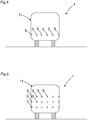
- FIG. 4 shows the vehicle 11 from the FIGS. 1 to 3 in a front view with the sensors 5.
- FIG. 5 shows a vehicle 11 according to another embodiment in a front view.
- the sensors 5 are each arranged in a plurality of spaced rows.
- a spatial monitoring area or a spatial protective field is formed.
- the sensors 5 are preferably arranged at equal intervals.
- the sensors 5 are arranged in a plane transverse to the direction of movement, wherein the detection beams are arranged at an acute angle to the direction of movement of the part.
- the sensors are arranged in at least two different directions.
- the detection beams of two respective groups of sensors each show each other, so that the detection beams intersect.
- the angles of the detection beams are identical, but with different angular directions or with different signs.
- the sensors are arranged in a common housing.
- the sensors can already be pre-assembled in a housing.
- the pre-assembled in the common housing sensors can then be mounted directly on the moving part. This facilitates assembly, for example on a vehicle or a movable machine part.
Description
Die vorliegende Erfindung betrifft eine Vorrichtung nach dem Oberbegriff von Anspruch 1.The present invention relates to a device according to the preamble of
Derzeit werden Laserscanner oder auch Lichtgitter zur Gefahrbereichsüberwachung eingesetzt. Weiter ist es üblich, sogenannte mechanische "Bumper" an Fahrzeugen zu installieren, die ansprechen, wenn das Fahrzeug ein Hindernis berührt. Ein Bumper ist ein mechanischer Berührungsschalter, der an der Außenkontur des Fahrzeuges angeordnet ist.Currently, laser scanners or light grids are used for hazardous area monitoring. It is also common to install so-called mechanical "bumpers" on vehicles that respond when the vehicle touches an obstacle. A bumper is a mechanical touch switch, which is arranged on the outer contour of the vehicle.
Bumper sind teuer, arbeiten nicht kontaktfrei und sind nur für Anwendungen mit quasi sehr kurzen Reichweiten beschränkt.Bumpers are expensive, non-contact, and limited to applications with quasi-very short ranges.
Laserscanner sind ebenfalls teuer und für viele moderne Kleinstfahrzeuge zu groß. Beide Lösungen sind nicht flexibel einsetzbar, was jedoch bei Kleinfahrzeugen zunehmend erforderlich wird.Laser scanners are also expensive and too big for many modern micro vehicles. Both solutions are not flexible, but this is increasingly required for small vehicles.
Beispielsweise offenbart die
Die
Eine Aufgabe der Erfindung besteht darin, eine kostengünstige und flexibel einsetzbare Vorrichtung bereitzustellen zur Überwachung von Überwachungsbereichen.An object of the invention is to provide an inexpensive and flexible device for monitoring surveillance areas.
Die Aufgabe wird gemäß Anspruch 1 gelöst durch eine Vorrichtung zum sicheren Überwachen eines Überwachungsbereichs eines beweglichen Teils bei einer Bewegung des Teils in Bewegungsrichtung, mit mehreren Sensoren, und mit einer Auswerteeinheit zum Auswerten der Sensoren, wobei die Sensoren quer zur Bewegungsrichtung beabstandet zueinander angeordnet sind, wobei die Sensoren ein flächiges Schutzfeld bilden, welches sich über die Breite des Teils erstreckt, wobei die Sensoren berührungslos wirkende abstandsmessende Sensoren sind, wobei die Sensoren einen Detektionsstrahl zum Erfassen von Objekten im Überwachungsbereich aufweisen und die Detektionsstrahlen der Sensoren in einem spitzen Winkel zur Bewegungsrichtung des Teils angeordnet sind, wobei die Sensoren Lichtlaufzeitsensoren sind, wobei das bewegliche Teil ein führerloses Transportfahrzeug ist, wobei die Bewegung die Fahrzeugbewegung ist und die Bewegungsrichtung die Fahrzeugbewegungsrichtung ist.The object is achieved according to
Sicherheit ist gemäß vorliegender Erfindung Sicherheit im Sinne von Maschinensicherheit. Beispielsweise regelt die Norm EN/IEC 61496 die Anforderungen an einen sicheren Sensor bzw. eine sichere berührungslos wirkende Schutzeinrichtung (BWS) zur Absicherung von Gefahrenbereichen. Maschinensicherheit ist in der Norm EN13849 geregelt. Die Sicherheit wird beispielsweise durch einen zweikanaligen oder zweikanalig diversitären Aufbau einer Auswerteeinheit zur Fehleraufdeckung und zur Funktionsprüfung gewährleistet. Der abstandsmessende Sensor bzw. Distanzsensor gemäß vorliegender Erfindung ist beispielsweise eigensicher ausgebildet und erkennt interne Fehler. Bei Entdeckung eines Fehlers wird beispielsweise ein Fehlersignal generiert. Weiter verfügt der Sensor bzw. Distanzsensor optional über eine Sensortestung.Safety according to the present invention is safety in the sense of machine safety. For example, the standard EN / IEC 61496 regulates the requirements for a safe sensor or a safe non-contact protective device (ESPE) for the protection of hazardous areas. Machine safety is regulated in the standard EN13849. The security is ensured, for example, by a two-channel or two-channel diversitären structure of an evaluation unit for fault detection and functional testing. The distance-measuring sensor or distance sensor according to the present invention, for example, intrinsically safe and detects internal errors. When an error is detected, for example, an error signal is generated. Furthermore, the sensor or distance sensor optionally has a sensor test.
Die Auswerteeinheit erkennt Schutzfeldverletzungen und kann ein sicherheitsgerichtetes Abschaltsignal ausgeben, um eine gefahrbringende Bewegung des Teils zu stoppen bzw. das Teil abzubremsen. Das kann z. B. über sichere Schaltsignale z.B. OSSD-Signale (Output Safety Switching Device-Signale) oder sichere Distanzdaten, Abstandsdaten bzw. sichere Ortsdaten des Eingriffsereignisses realisiert werden. Beispielsweise ist die Auswerteeinheit zweikanalig ausgebildet.The evaluation unit detects protective field violations and can output a safety-related switch-off signal in order to stop a dangerous movement of the part or to decelerate the part. This can z. B. via secure switching signals e.g. OSSD signals (output safety switching device signals) or safe distance data, distance data or safe location data of the intervention event can be realized. For example, the evaluation unit is designed with two channels.
Die Überwachung erfolgt mit einer Anzahl einfacher, eindimensional tastender Distanzmesssensoren unter Ausnutzung der Bewegung des Teils und einer Ausrichtung der Sensoren, bei der die Tastrichtung in einem Winkel zur Bewegungsrichtung des Teils steht.The monitoring is done with a number of simple, one-dimensionally probing distance measuring sensors utilizing the movement of the part and an orientation of the sensors, wherein the scanning direction is at an angle to the direction of movement of the part.
Unter der Annahme, dass ein Eingriff in das Schutzfeld nur in Richtung der Ebene des Schutzfeldes erfolgt und nicht quer zum Schutzfeld, stellt die Vorrichtung sicher, dass ein definiertes Objekt, beispielsweise ein Bein immer und spätestens nach dem Zurücklegen einer bestimmten Strecke des Teils detektiert wird. Diese Strecke kann als Bremszone definiert werden. Die Sensoren sind dabei bevorzugt in einem Winkel zu einer Seitenfläche des Fahrzeuges ausgerichtet.Assuming that an intervention in the protective field takes place only in the direction of the plane of the protective field and not across the protective field, the device ensures that a defined object, for example a leg, is always detected and at the latest after a certain distance of the part has been covered , This route can be defined as a braking zone. The sensors are preferably aligned at an angle to a side surface of the vehicle.
Aufgrund des Winkels zwischen Detektionsstrahl und Bewegungsrichtung verschiebt sich der Taststrahl bei Annäherung des Teils seitlich relativ zu einem statischen Objekt im Überwachungsbereich. Die Detektionsstrahlen sind dabei parallel zueinander angeordnet.Due to the angle between the detection beam and the direction of movement of the scanning beam shifts when approaching the part laterally relative to a static object in the surveillance area. The detection beams are arranged parallel to each other.
Vom Eintreten eines Objektes in die Bremszone bis zum Erreichen des Schutzfeldes wird je nach Neigungswinkel ein Lateralbereich vom Detektionsstrahl überstrichen. Eine Anordnung von Taststrahlen, die innerhalb des Bewegungsweges, der der Länge der Bremszone entspricht, einen Lateralbereich überstreicht, der höchstens noch nicht erfasste Lücken kleiner als eine minimale Objektgröße enthält, wird das Objekt in jedem Fall bis zum Erreichen des Schutzfeldes erfassen, je nach Position auch schon vorher.From the entry of an object into the braking zone until reaching the protective field, a lateral area is swept by the detection beam, depending on the angle of inclination. An array of tactile rays sweeping a lateral area within the path of travel corresponding to the length of the braking zone that contains at most unrecognized gaps less than a minimum object size will, in each case, detect the object until it reaches the protective field, depending on the position also before.
Die Vorrichtung kann vorzugsweise als integriertes System aus einer Kette von Sensoren mit einfachen integrierten Sensormodulen und einer zentralen Auswerteeinheit realisiert werden.The device can preferably be realized as an integrated system comprising a chain of sensors with simple integrated sensor modules and a central evaluation unit.
Soll das Teil aus einem statischen bewegungslosen Zustand heraus bewegt werden, kann es vorkommen, dass ggf. bereits ein Objekt im Schutzbereich vorhanden ist, jedoch dies nicht detektiert werden kann, da sich dieses Objekt zwischen den Detektionsstrahlen befindet. Hier kann es beispielsweise optional vorgesehen sein, dass das Teil aus dem Stand heraus zunächst mit einer geringen ungefährlichen Geschwindigkeit bewegt wird, bis sichergestellt ist, dass sich kein Objekt im Schutzfeld befindet.If the part is to be moved out of a static motionless state, it may happen that an object may already be present in the protected area, but this can not be detected, since this object is located between the detection beams. Here, for example, it may optionally be provided that the part is first moved out of the state with a low harmless speed, until it is ensured that no object is located in the protective field.
Der spitze Winkel α beträgt vorzugsweise nur wenige Grad. Beispielsweise 1° bis 20°, oder 1° bis 10° oder 1° bis 5°. Der spitze Winkel α ist dabei bevorzugt in einem Winkel zu einer Seitenfläche des Fahrzeuges ausgerichtet.The acute angle α is preferably only a few degrees. For example, 1 ° to 20 °, or 1 ° to 10 ° or 1 ° to 5 °. The acute angle α is preferably aligned at an angle to a side surface of the vehicle.
Der Winkel ist dabei abhängig von dem parallelen Abstand der Detektionsstrahlen bzw. dem Abstand der Sensoren und der Länge des Überwachungsbereiches. Weiter ist der Abstand der Sensoren abhängig von der zu detektierenden Objektgröße.The angle is dependent on the parallel distance of the detection beams or the distance of the sensors and the length of the monitored area. Furthermore, the distance between the sensors depends on the object size to be detected.
Der Winkel ergibt sich optional aus der folgenden Gleichung: ![]()
![]()
Gemäß einer Weiterbildung der Erfindung ist der Winkel der Sensoren einstellbar. D. h. beispielsweise je nach Länge des gewünschten Überwachungsbereiches kann der Winkel vergrößert oder verkleinert werden. Je kleiner der Überwachungsbereich in Fahrtrichtung ist, desto größer ist der Winkel α. Der Winkel α kann beispielsweise dynamisch verändert werden, um unterschiedlich lange Überwachungsbereiche einzustellen.According to one embodiment of the invention, the angle of the sensors is adjustable. Ie. For example, depending on the length of the desired surveillance area, the angle can be increased or decreased. The smaller the surveillance area in the direction of travel, the greater the angle α. The angle α can be changed dynamically, for example, in order to set monitoring areas of different lengths.
Gemäß der Erfindung ist das bewegliche Teil ein führerloses Transportfahrzeug, wobei die Bewegung die Fahrzeugbewegung ist und die Bewegungsrichtung die Fahrzeugbewegungsrichtung ist.According to the invention, the movable part is a driverless transport vehicle, wherein the movement is the vehicle movement and the movement direction is the vehicle movement direction.
Gemäß dieser Ausbildung ist es möglich, vor dem Fahrzeug ein Schutzfeld mit einfachen Mitteln zu realisieren.According to this embodiment, it is possible to realize a protective field in front of the vehicle with simple means.
Die Sensoren können beispielsweise an einer Seite des Fahrzeugs in Fahrtrichtung angeordnet sein. Jedoch können auch mehrere Seiten oder auch alle Seiten des Fahrzeuges mit den Sensoren ausgebildet sein. Insbesondere wenn sich das Fahrzeug in alle Richtungen bewegen kann und insbesondere auch ein Rückwärtsfahren möglich sein soll, sind Sensoren insbesondere an der Rückseite und an den Seitenwänden des Fahrzeuges vorgesehen.The sensors can be arranged, for example, on one side of the vehicle in the direction of travel. However, several pages or even all sides of the vehicle may be formed with the sensors. In particular, if the vehicle can move in all directions and in particular a reverse drive should be possible, sensors are provided in particular on the back and on the side walls of the vehicle.
Gemäß der Erfindung sind die Sensoren Lichtlaufzeitsensoren. Ein Lichtlaufzeitsensor bzw. ein Distanzsensor bzw. ein Lichttaster nach dem Lichtlaufzeitprinzip weist mindestens einen Lichtsender auf, der aufeinanderfolgende Lichtimpulse in einen Messbereich bzw. Überwachungsbereich aussendet und mindestens einen Lichtempfänger, welcher die an einem Objekt im Messbereich zurückgeworfenen Lichtimpulse aufnimmt und in Form von elektrischen Empfangssignalen einer Steuer- und Auswerteeinheit zuführt, die unter Berücksichtigung der Lichtgeschwindigkeit aus der Zeit zwischen Aussendung und Empfang des Lichtimpulses ein für den Abstand des Objektes zum Lichttaster repräsentatives Abstandssignal ermittelt.According to the invention, the sensors are light transit time sensors. A light transit time sensor or a distance sensor or a light sensor according to the time of flight principle has at least one light transmitter which emits successive light pulses into a measurement area or monitoring area and at least one light receiver which receives the light pulses reflected back from an object in the measurement area and in the form of electrical reception signals a control and evaluation unit which, taking into account the speed of light from the time between Transmission and reception of the light pulse determined a representative of the distance of the object to the light sensor distance signal.
Gemäß einer bevorzugten Ausführungsform weist ein Lichtempfänger des Distanzsensors mindestens ein Array aus Einzelphotonenlawinendioden auf.According to a preferred embodiment, a light receiver of the distance sensor has at least one array of single photon avalanche diodes.
Einzelphotonenlawinendioden werden auch synonym als ,Single Photon Avalanche Diode' kurz SPAD bezeichnet. Andere gängige Bezeichnungen sind ,Silicon Photomultiplier' (SiPM), 'Geigermode Avalanche Photon Diode' oder 'Single Photon Counting Diode'. Einzelphotonenlawinendioden sind in Standard CMOS-Technologie realisierbare photoempfindliche Detektoren, die ähnlich wie Avalanche Photodioden einfallende Photonen in Strompulse konvertieren. Im Gegensatz zu Avalanche Photodioden werden Einzelphotonenlawinendioden jedoch über einer Durchbruchsspannung betrieben. Damit löst bereits ein einzelnes einfallendes Photon einen Lawineneffekt aus, der als Strompuls detektiert werden kann. Aufgrund der hohen Sensitivität, nämlich einem Verstärkungsfaktor von 106 können bereits geringste Empfangsleistungen bis zu Einzelphotonen detektiert werden.Single photon avalanche diodes are also referred to synonymously as 'single photon avalanche diode' or SPAD for short. Other common names are 'Silicon Photomultiplier' (SiPM), 'Geiger Mode Avalanche Photon Diode' or 'Single Photon Counting Diode'. Single-photon avalanche diodes are standard photosensitive detectors using standard CMOS technology, which, like avalanche photodiodes, convert incident photons into current pulses. However, unlike avalanche photodiodes, single photon avalanche diodes operate over a breakdown voltage. Thus, even a single incident photon triggers an avalanche effect, which can be detected as a current pulse. Due to the high sensitivity, namely an amplification factor of 10 6 , even the lowest reception power can be detected down to single photons.
Eine Verwendung eines Lichtlaufzeitsensors, insbesondere die Verwendung von Einzelphotonenlawinendioden in Kombination mit Pulslasern liefern Abstandsinformationen mit einer Genauigkeit von beispielsweise bis zu ca. einem Millimeter. Gleichzeitig erlaubt eine einfache Vorsatzoptik über eine Fokussierung die Realisierung von guter Ortsselektivität und Abgrenzung gegenüber Störlicht.Use of a light transit time sensor, in particular the use of single photon avalanche diodes in combination with pulse lasers, provides distance information with an accuracy of, for example, up to about one millimeter. At the same time, a simple optical attachment via focusing allows the realization of good spatial selectivity and differentiation from stray light.
Zur Entfernungsmessung sind verschiedene Lichtlaufzeitverfahren mit einer entsprechenden Auswertung implementierbar.For distance measurement, different light transit time methods can be implemented with a corresponding evaluation.
Es kann ein Pulsverfahren vorgesehen sein. Beispielsweise sind ein oder mehrere Zeit-zu-Digital-Konverter (time-to-digital-converter) für das Pulsverfahren vorgesehen, in dem jedes Einzelphotonenereignis mit einem Zeitstempel versehen wird. Bei einem Nutzsignal treten daher mehrere Zeitstempel korreliert auf. Die Messwertgenerierung erfolgt statistisch. Hintergrundlicht erzeugt hingegen zufällig verteilte Zeitstempel.It may be provided a pulse method. For example, one or more time-to-digital converters are provided for the pulse method in which each single-photon event is time-stamped. For a useful signal, therefore, multiple timestamps occur correlated. The measured value is generated statistically. Background light, however, generates randomly distributed timestamps.
Weiter kann ein CW-Verfahren (Continuous Wave) bzw. das synonyme Dauerstrich-Verfahren eingesetzt werden, wobei ein zeitlich durchgängig moduliertes Lichtsignal eingesetzt wird. Bei diesem Verfahren werden über ein Gating-Signal die Einzelphotonenevents in zwei Zähler verteilt und aus dem Verhältnis der Zählerstände eine Phase berechnet.Furthermore, a CW method (continuous wave) or the synonymous continuous wave method can be used, wherein a continuous light signal is used throughout. In this method, the gating signal, the Einzelphotonenevents divided into two counters and calculated from the ratio of the meter readings a phase.
Weiter können analoge Signale des Einzelphotonendiodenarrays ausgewertet werden. Diese werden mit einem Schwellwert verglichen, werden gesampelt oder werden mit statistischen Methoden ausgewertet.Furthermore, analog signals of the single-photon diode array can be evaluated. These are compared with a threshold, sampled or evaluated using statistical methods.
Bei der Auswertung nach dem Lichtlaufzeitverfahren kann zusätzlich zum Abstandswert auch ein Amplitudenwert generiert werden, z. B. durch ein Histogramm der Zeitstempel, durch eine Zählrate oder durch eine Spannungsamplitude bei einer analogen Auswertung. Durch den Amplitudenwert kann eine Plausibilitätsprüfung, insbesondere bei sicherheitstechnischen Anwendungen durchgeführt werden.In the evaluation according to the time of flight method, an amplitude value can be generated in addition to the distance value, for. B. by a histogram of the time stamp, by a count rate or by a voltage amplitude in an analog evaluation. The amplitude value can be used to carry out a plausibility check, in particular in safety-related applications.
Die Verwendung von Einzelphotonenlawinendioden bietet folgende Vorteile: Einzelphotonenlawinendioden sind in einem Standard CMOS Prozess herstellbar. Damit ist der Lichttaster hoch integrierbar, z. B. als ASIC. Der Lichtsender, beispielsweise ein VSCEL, eine Laserdiode oder eine Leuchtdiode und die Steuer- und Auswerteeinheit bzw. eine getrennte Lichtsenderansteuerung sind ebenfalls auf dem Chip bzw. im Gehäuse integrierbar.The use of single-photon avalanche diodes offers the following advantages: Single-photon avalanche diodes can be produced in a standard CMOS process. Thus, the light sensor is highly integrated, z. As an ASIC. The light transmitter, for example a VSCEL, a laser diode or a light emitting diode and the control and evaluation unit or a separate light transmitter drive can also be integrated on the chip or in the housing.
In Weiterbildung der Erfindung weisen die Sensoren gleichmäßige Abstände auf. Durch die gleichmäßigen Abstände der Sensoren und eine jeweils identische Winkelausrichtung der Detektionsstrahlen wird eine gleichmäßige Auflösung innerhalb des Schutzfeldes erreicht.In a further development of the invention, the sensors have uniform distances. Due to the uniform distances of the sensors and each identical angular orientation of the detection beams uniform resolution within the protective field is achieved.
In Weiterbildung der Erfindung ist wenigstens ein Detektionsstrahl eines Sensors, der am Rand des Schutzfeldes angeordnet ist, in Richtung einer Bewegungsrichtung des Teils angeordnet. Dadurch wird der Rand des Schutzfeldes gegen seitliches Eindringen überwacht. Diese Detektionsstrahlen am Rand sind dabei ggf. nicht parallel zu den übrigen Lichtstrahlen angeordnet, sondern direkt in Bewegungsrichtung bzw. parallel zur Bewegungsrichtung angeordnet. Ein parallel zur Bewegungsrichtung angeordneter Detektionsstrahl kann an beiden gegenüberliegenden seitlichen Rändern des Schutzfeldes bzw. Überwachungsbereiches vorgesehen sein.In a development of the invention, at least one detection beam of a sensor, which is arranged on the edge of the protective field, is arranged in the direction of a movement direction of the part. As a result, the edge of the protective field is monitored against lateral penetration. If necessary, these detection beams at the edge are not arranged parallel to the other light beams, but are arranged directly in the direction of movement or parallel to the direction of movement. A detection beam arranged parallel to the direction of movement may be provided on both opposite lateral edges of the protective field or monitoring area.
In Weiterbildung der Erfindung weisen die Sensoren eine Linienoptik auf, wodurch im Querschnitt ein linienförmiger Detektionsstrahl gebildet wird mit einer Ausdehnung quer zur Detektionsrichtung. Der Detektionsstrahl ist damit flächig ausgebildet, wodurch auch ein räumliches Schutzfeld ermöglicht wird. Beispielsweise ist die Fläche des Detektionsstrahls quer zum Winkel α ausgerichtet.In a further development of the invention, the sensors have line optics, whereby a line-shaped detection beam is formed in cross-section with an extent transverse to the detection direction. The detection beam is thus flat, whereby also a spatial protective field is made possible. For example, the surface of the detection beam is oriented transversely to the angle α.
In Weiterbildung der Erfindung sind die Sensoren jeweils in mehreren beabstandeten Reihen angeordnet. Dadurch wird ein räumliches Schutzfeld bzw. ein räumlicher Überwachungsbereich gebildet. Dabei sind die Sensoren bevorzugt in gleichen Abständen angeordnet. Die Sensoren sind dabei ein einer Ebene quer zur Bewegungsrichtung angeordnet, wobei die Detektionsstrahlen in einem spitzen Winkel zur Bewegungsrichtung des Teils angeordnet sind.In a further development of the invention, the sensors are each arranged in a plurality of spaced rows. As a result, a spatial protective field or a spatial monitoring area is formed. The sensors are preferably arranged at equal intervals. The sensors are arranged in a plane transverse to the direction of movement, wherein the detection beams are arranged at an acute angle to the direction of movement of the part.
In Weiterbildung der Erfindung sind die Sensoren in mindestens zwei unterschiedlichen Richtungen angeordnet. Beispielsweise zeigen die Detektionsstrahlen von zwei jeweiligen Gruppen von Sensoren jeweils zueinander, so dass sich die Detektionsstrahlen kreuzen. Dabei sind die Winkel der Detektionsstrahlen zwar identisch, jedoch mit unterschiedlichen Winkelrichtungen bzw. mit unterschiedlichen Vorzeichen.In a further development of the invention, the sensors are arranged in at least two different directions. For example, the detection beams of two respective groups of sensors each face each other, so that the detection beams intersect. Although the angles of the detection beams are identical, but with different angular directions or with different signs.
In Weiterbildung der Erfindung sind die Sensoren in einem gemeinsamen Gehäuse angeordnet. Dadurch können die Sensoren bereits in einem Gehäuse vormontiert bereitgestellt werden. Die im gemeinsamen Gehäuse vormontierten Sensoren können dann direkt an dem beweglichen Teil montiert werden. Dadurch wird eine Montage, beispielsweise an einem Fahrzeug oder einem beweglichen Maschinenteil, erleichtert.In a further development of the invention, the sensors are arranged in a common housing. As a result, the sensors can already be pre-assembled in a housing. The pre-assembled in the common housing sensors can then be mounted directly on the moving part. This facilitates assembly, for example on a vehicle or a movable machine part.
Die Erfindung wird nachstehend auch hinsichtlich weiterer Vorteile und Merkmale unter Bezugnahme auf die beigefügte Zeichnung anhand von Ausführungsbeispielen erläutert. Die Figuren der Zeichnung zeigen in:
Figur 1- eine Vorrichtung gemäß vorliegender Erfindung;
Figur 2bis 3- ein Fahrzeug bzw. ein Teil mit Sensoren;
Figur 4bis 5- ein Fahrzeug mit Sensoren in einer Frontansicht.
- FIG. 1
- a device according to the present invention;
- FIGS. 2 to 3
- a vehicle or a part with sensors;
- FIGS. 4 to 5
- a vehicle with sensors in a front view.
In den nachfolgenden Figuren sind identische Teile mit identischen Bezugszeichen versehen.In the following figures, identical parts are provided with identical reference numerals.
Gemäß
Gemäß dieser Ausbildung ist es möglich, vor dem Fahrzeug 11 ein Schutzfeld 7 mit einfachen Mitteln zu realisieren.According to this embodiment, it is possible to realize a
Die Sensoren sind gemäß
Gemäß
Insbesondere wenn das Maschinenteil 13 nur eine geradlinige Bewegung durchführt, können die Sensoren 5 in Bewegungsrichtung 4 angeordnet werden, so dass die Detektionsstrahlen 9 der Sensoren 5 in einem spitzen Winkel α zur Bewegungsrichtung 4 des Teils 3 angeordnet sind.In particular, when the
Bei dem Maschinenteil 13 kann es sich beispielsweise um einen Maschinenschlitten handeln, in dessen Bewegungsrichtung 4 die Sensoren 5 angeordnet sind.The
Die Überwachung erfolgt gemäß Figur mit einer Anzahl einfacher, eindimensional tastender Distanzmesssensoren unter Ausnutzung der Bewegung des Fahrzeugs 11 und einer Ausrichtung der Sensoren 5, bei der die Tastrichtung in einem Winkel α zur Bewegungsrichtung 4 des Fahrzeugs 11 steht.The monitoring is carried out according to FIG with a number of simple, one-dimensional grower distance measuring sensors taking advantage of the movement of the
Durch die Detektionsstrahlen 9 der Sensoren 5 wird ein Schutzfeld 7 gebildet und vor dem Schutzfeld 7 eine Bremszone 15. Die Detektionsstrahlen 9 sind dabei parallel zueinander angeordnet.By the
Aufgrund des Winkels α zwischen Detektionsstrahl 9 und Bewegungsrichtung 4 verschiebt sich der Detektionsstrahl 9 bei Annäherung des Fahrzeugs 11 seitlich relativ zu einem statischen Objekt 10 im Überwachungsbereich 2.Due to the angle α between the
Vom Eintreten eines Objektes 10 in die Bremszone 15 bis zum Erreichen des Schutzfeldes 7 wird je nach Neigungswinkel α ein Lateralbereich vom Detektionsstrahl 9 überstrichen.From the entry of an
Die Anordnung von Detektionsstrahlen 9, die innerhalb des Bewegungsweges, der der Länge der Bremszone 15 entspricht, einen Lateralbereich überstreicht, der höchstens noch nicht erfasste Lücken kleiner als eine minimale Objektgröße enthält, wird das Objekt 10 in jedem Fall bis zum Erreichen des Schutzfeldes 7 erfassen, je nach Position auch schon vorher. Das ist in den
In
Der spitze Winkel α ist abhängig von dem parallelen Abstand 14 der Detektionsstrahlen 9 bzw. dem Abstand 14 der Sensoren 5 und der Länge des Überwachungsbereiches 2. Weiter ist der Abstand 14 der Sensoren 5 abhängig von der zu detektierenden Objektgröße. Beispielsweise beträgt der Winkel 1° bis 20°, oder 1° bis 10° oder 1° bis 5°.The acute angle α is dependent on the
Der Winkel α ergibt sich optional aus der folgenden Gleichung: ![]()
![]()
Gemäß
Gemäß
Gemäß
Gemäß
Dieser Detektionsstrahl 9.1 am Rand ist dabei nicht parallel zu den übrigen Lichtstrahlen 9 angeordnet, sondern direkt in Bewegungsrichtung 4 bzw. parallel zur Bewegungsrichtung 4 angeordnet.This detection beam 9.1 at the edge is not arranged parallel to the other
Ein parallel zur Bewegungsrichtung 4 angeordneter Detektionsstrahl 9.1 kann an beiden gegenüberliegenden seitlichen Rändern des Schutzfeldes 7 bzw. Überwachungsbereichs 2 vorgesehen sein.A detection beam 9.1 arranged parallel to the direction of
Gemäß einer nicht dargestellten Ausführungsform weisen die Sensoren 5 eine Linienoptik auf, wodurch im Querschnitt ein linienförmiger Detektionsstrahl 9 gebildet wird mit einer Ausdehnung quer zur Detektionsrichtung. Der Detektionsstrahl 9 ist damit flächig ausgebildet, wodurch auch ein räumliches Schutzfeld 7 bzw. räumlicher Überwachungsbereich 2 ermöglicht wird. Beispielsweise ist die Fläche des Detektionsstrahls 9 quer zum Winkel α ausgerichtet.According to an embodiment, not shown, the
Gemäß einer nicht dargestellten Ausführungsform sind die Sensoren in mindestens zwei unterschiedlichen Richtungen angeordnet. Dabei zeigen die Detektionsstrahlen von zwei jeweiligen Gruppen von Sensoren jeweils zueinander, so dass sich die Detektionsstrahlen kreuzen. Dabei sind die Winkel der Detektionsstrahlen zwar identisch, jedoch mit unterschiedlichen Winkelrichtungen bzw. mit unterschiedlichen Vorzeichen.According to an embodiment not shown, the sensors are arranged in at least two different directions. In this case, the detection beams of two respective groups of sensors each show each other, so that the detection beams intersect. Although the angles of the detection beams are identical, but with different angular directions or with different signs.
Gemäß einer nicht dargestellten Ausführungsform sind die Sensoren in einem gemeinsamen Gehäuse angeordnet. Dadurch können die Sensoren bereits in einem Gehäuse vormontiert bereitgestellt werden. Die im gemeinsamen Gehäuse vormontierten Sensoren können dann direkt an dem beweglichen Teil montiert werden. Dadurch wird eine Montage, beispielsweise an einem Fahrzeug oder einem beweglichen Maschinenteil erleichtert.According to one embodiment, not shown, the sensors are arranged in a common housing. As a result, the sensors can already be pre-assembled in a housing. The pre-assembled in the common housing sensors can then be mounted directly on the moving part. This facilitates assembly, for example on a vehicle or a movable machine part.
- 1 Vorrichtung1 device
- 2 Überwachungsbereich2 surveillance area
- 3 bewegliches Teil3 moving part
- 4 Bewegungsrichtung4 direction of movement
- 5 Sensoren5 sensors
- 6 Auswerteeinheit6 evaluation unit
- 7 Schutzfeld7 protective field
- 8 Breite des Teils8 Width of the part
- 9, 9.1 Detektionsstrahl9, 9.1 detection beam
- 10 Objekte10 objects
- 11 Fahrzeug11 vehicle
- 12 führerloses Transportfahrzeug12 driverless transport vehicle
- 13 Maschinenteil13 machine part
- 14 Abstand14 distance
- 15 Bremszone15 braking zone
- 16 Gehäuse16 housing
- α spitzer Winkelα acute angle
Claims (7)
- An apparatus for the secure monitoring of a monitored zone (2) of a moving part (3) on a movement of the part (3) in the direction of movement (4) having a plurality of sensors (5) and having an evaluation unit (6) for evaluating the sensors (5),
wherein the sensors (5) are arranged spaced apart from one another transversely to the direction of movement (4);
wherein the sensors (5) form an areal protected field (7) that extends over the width of the part (3);
wherein the sensors (5) are contactlessly acting distance-measuring sensors; and
wherein the sensors (5) have a detection beam (9) for detecting objects (10) in the monitored zone (2),
characterized in that
the detection beams (9) of the sensors (5) are arranged at an acute angle α with respect to the direction of movement (4) of the part (3), with the sensors (5) being time of flight sensors; with the moving part (3) being a driverless transport vehicle (12); and with the movement being the vehicle movement and the direction of movement being the direction of movement of the vehicle. - An apparatus in accordance with the preceding claim, characterized in that the sensors (5) have uniform intervals (14).
- An apparatus in accordance with at least one of the preceding claims, characterized in that at least one detection beam (9) of a sensor (5) that is arranged at the margin of the protected field (7) is arranged in the direction of a direction of movement (4) or in parallel with the direction of movement of the part (3).
- An apparatus in accordance with at least one of the preceding claims, characterized in that the sensors (5) have a line optics, whereby a linear detection beam (9) having an extent transverse to the direction of detection is formed in cross-section.
- An apparatus in accordance with at least one of the preceding claims, characterized in that the sensors are each arranged in a plurality of spaced apart rows.
- An apparatus in accordance with at least one of the preceding claims, characterized in that the sensors (5) are arranged in at least two different directions.
- An apparatus in accordance with at least one of the preceding claims, characterized in that the sensors (5) are arranged in a common housing (16).
Applications Claiming Priority (1)
| Application Number | Priority Date | Filing Date | Title |
|---|---|---|---|
| DE102016103028.7A DE102016103028A1 (en) | 2016-02-22 | 2016-02-22 | Device for monitoring a surveillance area |
Publications (2)
| Publication Number | Publication Date |
|---|---|
| EP3208511A1 EP3208511A1 (en) | 2017-08-23 |
| EP3208511B1 true EP3208511B1 (en) | 2018-05-09 |
Family
ID=58098436
Family Applications (1)
| Application Number | Title | Priority Date | Filing Date |
|---|---|---|---|
| EP17156037.8A Active EP3208511B1 (en) | 2016-02-22 | 2017-02-14 | Device for monitoring a monitored area of a driverless vehicle |
Country Status (2)
| Country | Link |
|---|---|
| EP (1) | EP3208511B1 (en) |
| DE (1) | DE102016103028A1 (en) |
Families Citing this family (4)
| Publication number | Priority date | Publication date | Assignee | Title |
|---|---|---|---|---|
| DE102017127065B4 (en) * | 2017-11-17 | 2023-04-27 | Sick Ag | Area sensor and autonomous self-driving vehicle with an area sensor |
| DE202018006124U1 (en) | 2018-03-22 | 2019-06-26 | Sick Ag | sensor |
| DE102018113359B4 (en) | 2018-06-05 | 2020-07-30 | Sick Ag | Sensor system with optoelectronic distance sensors |
| DE102018122263B4 (en) | 2018-09-12 | 2021-03-18 | Sick Ag | Autonomous vehicle |
Family Cites Families (13)
| Publication number | Priority date | Publication date | Assignee | Title |
|---|---|---|---|---|
| US5314037A (en) * | 1993-01-22 | 1994-05-24 | Shaw David C H | Automobile collision avoidance system |
| DE19512681A1 (en) | 1995-04-07 | 1996-10-10 | Hipp Johann | Safety device for collision avoidance of driverless vehicles |
| DE19729915A1 (en) * | 1997-02-19 | 1998-08-27 | Mannesmann Ag | Device and detection of moving objects |
| DE102005049159A1 (en) | 2004-10-21 | 2006-05-24 | Sick Ag | Monitoring method for vehicle surroundings, involves calculating occurrence of collision between vehicle and object, and transmitting to vehicle for adjusting at least one of its speed and its driving direction to prevent collision |
| DE102005055107A1 (en) * | 2005-11-18 | 2007-05-24 | Valeo Schalter Und Sensoren Gmbh | System for detecting objects in the surroundings of a motor vehicle |
| US7544945B2 (en) * | 2006-02-06 | 2009-06-09 | Avago Technologies General Ip (Singapore) Pte. Ltd. | Vertical cavity surface emitting laser (VCSEL) array laser scanner |
| ATE552514T1 (en) * | 2006-12-02 | 2012-04-15 | Sick Ag | OPTOELECTRONIC MULTILEVEL SENSOR AND METHOD FOR DETECTING OBJECTS |
| DE102007009244A1 (en) * | 2007-02-22 | 2008-08-28 | Sick Ag | Method for checking the functioning and / or adjustment of an optoelectronic sensor arrangement and optoelectronic sensor arrangement |
| DE102007038421B8 (en) * | 2007-08-14 | 2008-12-24 | Pepperl + Fuchs Gmbh | Safety device and method for monitoring an automatic door |
| DE102008050943B4 (en) * | 2008-10-10 | 2016-07-07 | Leuze Lumiflex Gmbh + Co. Kg | Optical sensor |
| GB201111691D0 (en) * | 2011-07-07 | 2011-08-24 | Lrb Global Consulting Ltd | A parking sensor |
| DE102012006347A1 (en) * | 2012-03-28 | 2013-10-02 | Brose Fahrzeugteile Gmbh & Co. Kg, Hallstadt | Method for determining distance between object e.g. person and motor vehicle e.g. car, involves receiving light reflected by object using light receiver at predetermined angle of incidence |
| DE102015101722A1 (en) * | 2014-02-06 | 2015-08-06 | Gm Global Technology Operations, Llc | Cost-effective compact LiDAR for automobiles |
-
2016
- 2016-02-22 DE DE102016103028.7A patent/DE102016103028A1/en not_active Withdrawn
-
2017
- 2017-02-14 EP EP17156037.8A patent/EP3208511B1/en active Active
Non-Patent Citations (1)
| Title |
|---|
| None * |
Also Published As
| Publication number | Publication date |
|---|---|
| DE102016103028A1 (en) | 2017-08-24 |
| EP3208511A1 (en) | 2017-08-23 |
Similar Documents
| Publication | Publication Date | Title |
|---|---|---|
| EP3136127B1 (en) | Distance sensor and method with a distance sensor | |
| EP3091272B1 (en) | Light grid | |
| EP2626722B1 (en) | Optoelectronic sensor and method for recording and determining the distance of an object | |
| EP3208511B1 (en) | Device for monitoring a monitored area of a driverless vehicle | |
| EP3091271B1 (en) | Light sensor | |
| EP3623845B1 (en) | Sensor and autonomous vehicle | |
| EP3633405A1 (en) | Measuring apparatus for geometric 3d-scanning of an environment having a plurality of emission channels and semiconductor photomultiplier sensors | |
| EP3220164B1 (en) | Method for operating a distance measuring monitoring sensor and monitoring sensor | |
| EP3418846B1 (en) | Device for safety control of a machine | |
| EP0372204A2 (en) | Optical-monitoring device | |
| DE202017103611U1 (en) | Device for safety control of a machine | |
| EP3415951B1 (en) | Optical sensor | |
| EP3839556B1 (en) | Optoelectronic sensor and method for detecting an object | |
| DE102017119283B4 (en) | Sensor system | |
| DE10001017A1 (en) | Optoelectronic sensor for detecting objects in monitored area, has light source and at least two photodiodes together with transmission and reception optical components | |
| EP3671276B1 (en) | Optoelectronic sensor and method for detecting an object | |
| DE102018113359B4 (en) | Sensor system with optoelectronic distance sensors | |
| DE102017103791B4 (en) | Optoelectronic sensor and method for detecting objects | |
| EP3872526B1 (en) | Device for monitoring a safety zone | |
| DE102010064682B3 (en) | Optoelectronic sensor and method for detecting and determining the distance of objects | |
| WO2017163169A1 (en) | Communication system having mobile transmitters and receivers | |
| DE202018006124U1 (en) | sensor | |
| DE202019103672U1 (en) | Sensor system | |
| DE102020129661A1 (en) | Operation of a laser scanner | |
| DE202020101055U1 (en) | Device for monitoring a protected area |
Legal Events
| Date | Code | Title | Description |
|---|---|---|---|
| PUAI | Public reference made under article 153(3) epc to a published international application that has entered the european phase |
Free format text: ORIGINAL CODE: 0009012 |
|
| STAA | Information on the status of an ep patent application or granted ep patent |
Free format text: STATUS: THE APPLICATION HAS BEEN PUBLISHED |
|
| AK | Designated contracting states |
Kind code of ref document: A1 Designated state(s): AL AT BE BG CH CY CZ DE DK EE ES FI FR GB GR HR HU IE IS IT LI LT LU LV MC MK MT NL NO PL PT RO RS SE SI SK SM TR |
|
| AX | Request for extension of the european patent |
Extension state: BA ME |
|
| STAA | Information on the status of an ep patent application or granted ep patent |
Free format text: STATUS: REQUEST FOR EXAMINATION WAS MADE |
|
| 17P | Request for examination filed |
Effective date: 20170906 |
|
| RBV | Designated contracting states (corrected) |
Designated state(s): AL AT BE BG CH CY CZ DE DK EE ES FI FR GB GR HR HU IE IS IT LI LT LU LV MC MK MT NL NO PL PT RO RS SE SI SK SM TR |
|
| GRAP | Despatch of communication of intention to grant a patent |
Free format text: ORIGINAL CODE: EPIDOSNIGR1 |
|
| STAA | Information on the status of an ep patent application or granted ep patent |
Free format text: STATUS: GRANT OF PATENT IS INTENDED |
|
| RIC1 | Information provided on ipc code assigned before grant |
Ipc: G01S 17/87 20060101ALI20171220BHEP Ipc: F16P 3/14 20060101AFI20171220BHEP Ipc: G05D 1/02 20060101ALI20171220BHEP Ipc: G01V 8/20 20060101ALI20171220BHEP Ipc: G01D 5/34 20060101ALI20171220BHEP Ipc: G01S 17/93 20060101ALI20171220BHEP Ipc: G01S 17/02 20060101ALI20171220BHEP |
|
| INTG | Intention to grant announced |
Effective date: 20180117 |
|
| GRAS | Grant fee paid |
Free format text: ORIGINAL CODE: EPIDOSNIGR3 |
|
| GRAA | (expected) grant |
Free format text: ORIGINAL CODE: 0009210 |
|
| STAA | Information on the status of an ep patent application or granted ep patent |
Free format text: STATUS: THE PATENT HAS BEEN GRANTED |
|
| AK | Designated contracting states |
Kind code of ref document: B1 Designated state(s): AL AT BE BG CH CY CZ DE DK EE ES FI FR GB GR HR HU IE IS IT LI LT LU LV MC MK MT NL NO PL PT RO RS SE SI SK SM TR |
|
| REG | Reference to a national code |
Ref country code: GB Ref legal event code: FG4D Free format text: NOT ENGLISH |
|
| REG | Reference to a national code |
Ref country code: CH Ref legal event code: EP Ref country code: AT Ref legal event code: REF Ref document number: 997898 Country of ref document: AT Kind code of ref document: T Effective date: 20180515 |
|
| REG | Reference to a national code |
Ref country code: DE Ref legal event code: R096 Ref document number: 502017000027 Country of ref document: DE Ref country code: IE Ref legal event code: FG4D Free format text: LANGUAGE OF EP DOCUMENT: GERMAN |
|
| REG | Reference to a national code |
Ref country code: NL Ref legal event code: MP Effective date: 20180509 |
|
| REG | Reference to a national code |
Ref country code: LT Ref legal event code: MG4D |
|
| PG25 | Lapsed in a contracting state [announced via postgrant information from national office to epo] |
Ref country code: SE Free format text: LAPSE BECAUSE OF FAILURE TO SUBMIT A TRANSLATION OF THE DESCRIPTION OR TO PAY THE FEE WITHIN THE PRESCRIBED TIME-LIMIT Effective date: 20180509 Ref country code: NO Free format text: LAPSE BECAUSE OF FAILURE TO SUBMIT A TRANSLATION OF THE DESCRIPTION OR TO PAY THE FEE WITHIN THE PRESCRIBED TIME-LIMIT Effective date: 20180809 Ref country code: BG Free format text: LAPSE BECAUSE OF FAILURE TO SUBMIT A TRANSLATION OF THE DESCRIPTION OR TO PAY THE FEE WITHIN THE PRESCRIBED TIME-LIMIT Effective date: 20180809 Ref country code: FI Free format text: LAPSE BECAUSE OF FAILURE TO SUBMIT A TRANSLATION OF THE DESCRIPTION OR TO PAY THE FEE WITHIN THE PRESCRIBED TIME-LIMIT Effective date: 20180509 Ref country code: LT Free format text: LAPSE BECAUSE OF FAILURE TO SUBMIT A TRANSLATION OF THE DESCRIPTION OR TO PAY THE FEE WITHIN THE PRESCRIBED TIME-LIMIT Effective date: 20180509 |
|
| PG25 | Lapsed in a contracting state [announced via postgrant information from national office to epo] |
Ref country code: RS Free format text: LAPSE BECAUSE OF FAILURE TO SUBMIT A TRANSLATION OF THE DESCRIPTION OR TO PAY THE FEE WITHIN THE PRESCRIBED TIME-LIMIT Effective date: 20180509 Ref country code: NL Free format text: LAPSE BECAUSE OF FAILURE TO SUBMIT A TRANSLATION OF THE DESCRIPTION OR TO PAY THE FEE WITHIN THE PRESCRIBED TIME-LIMIT Effective date: 20180509 Ref country code: HR Free format text: LAPSE BECAUSE OF FAILURE TO SUBMIT A TRANSLATION OF THE DESCRIPTION OR TO PAY THE FEE WITHIN THE PRESCRIBED TIME-LIMIT Effective date: 20180509 Ref country code: LV Free format text: LAPSE BECAUSE OF FAILURE TO SUBMIT A TRANSLATION OF THE DESCRIPTION OR TO PAY THE FEE WITHIN THE PRESCRIBED TIME-LIMIT Effective date: 20180509 Ref country code: GR Free format text: LAPSE BECAUSE OF FAILURE TO SUBMIT A TRANSLATION OF THE DESCRIPTION OR TO PAY THE FEE WITHIN THE PRESCRIBED TIME-LIMIT Effective date: 20180810 |
|
| PG25 | Lapsed in a contracting state [announced via postgrant information from national office to epo] |
Ref country code: PL Free format text: LAPSE BECAUSE OF FAILURE TO SUBMIT A TRANSLATION OF THE DESCRIPTION OR TO PAY THE FEE WITHIN THE PRESCRIBED TIME-LIMIT Effective date: 20180509 Ref country code: EE Free format text: LAPSE BECAUSE OF FAILURE TO SUBMIT A TRANSLATION OF THE DESCRIPTION OR TO PAY THE FEE WITHIN THE PRESCRIBED TIME-LIMIT Effective date: 20180509 Ref country code: CZ Free format text: LAPSE BECAUSE OF FAILURE TO SUBMIT A TRANSLATION OF THE DESCRIPTION OR TO PAY THE FEE WITHIN THE PRESCRIBED TIME-LIMIT Effective date: 20180509 Ref country code: DK Free format text: LAPSE BECAUSE OF FAILURE TO SUBMIT A TRANSLATION OF THE DESCRIPTION OR TO PAY THE FEE WITHIN THE PRESCRIBED TIME-LIMIT Effective date: 20180509 Ref country code: SK Free format text: LAPSE BECAUSE OF FAILURE TO SUBMIT A TRANSLATION OF THE DESCRIPTION OR TO PAY THE FEE WITHIN THE PRESCRIBED TIME-LIMIT Effective date: 20180509 Ref country code: RO Free format text: LAPSE BECAUSE OF FAILURE TO SUBMIT A TRANSLATION OF THE DESCRIPTION OR TO PAY THE FEE WITHIN THE PRESCRIBED TIME-LIMIT Effective date: 20180509 |
|
| REG | Reference to a national code |
Ref country code: DE Ref legal event code: R097 Ref document number: 502017000027 Country of ref document: DE |
|
| PG25 | Lapsed in a contracting state [announced via postgrant information from national office to epo] |
Ref country code: SM Free format text: LAPSE BECAUSE OF FAILURE TO SUBMIT A TRANSLATION OF THE DESCRIPTION OR TO PAY THE FEE WITHIN THE PRESCRIBED TIME-LIMIT Effective date: 20180509 Ref country code: IT Free format text: LAPSE BECAUSE OF FAILURE TO SUBMIT A TRANSLATION OF THE DESCRIPTION OR TO PAY THE FEE WITHIN THE PRESCRIBED TIME-LIMIT Effective date: 20180509 |
|
| PLBE | No opposition filed within time limit |
Free format text: ORIGINAL CODE: 0009261 |
|
| STAA | Information on the status of an ep patent application or granted ep patent |
Free format text: STATUS: NO OPPOSITION FILED WITHIN TIME LIMIT |
|
| 26N | No opposition filed |
Effective date: 20190212 |
|
| PG25 | Lapsed in a contracting state [announced via postgrant information from national office to epo] |
Ref country code: ES Free format text: LAPSE BECAUSE OF FAILURE TO SUBMIT A TRANSLATION OF THE DESCRIPTION OR TO PAY THE FEE WITHIN THE PRESCRIBED TIME-LIMIT Effective date: 20180509 |
|
| PG25 | Lapsed in a contracting state [announced via postgrant information from national office to epo] |
Ref country code: MC Free format text: LAPSE BECAUSE OF FAILURE TO SUBMIT A TRANSLATION OF THE DESCRIPTION OR TO PAY THE FEE WITHIN THE PRESCRIBED TIME-LIMIT Effective date: 20180509 Ref country code: LU Free format text: LAPSE BECAUSE OF NON-PAYMENT OF DUE FEES Effective date: 20190214 |
|
| REG | Reference to a national code |
Ref country code: BE Ref legal event code: MM Effective date: 20190228 |
|
| REG | Reference to a national code |
Ref country code: IE Ref legal event code: MM4A |
|
| PG25 | Lapsed in a contracting state [announced via postgrant information from national office to epo] |
Ref country code: AL Free format text: LAPSE BECAUSE OF FAILURE TO SUBMIT A TRANSLATION OF THE DESCRIPTION OR TO PAY THE FEE WITHIN THE PRESCRIBED TIME-LIMIT Effective date: 20180509 |
|
| PG25 | Lapsed in a contracting state [announced via postgrant information from national office to epo] |
Ref country code: IE Free format text: LAPSE BECAUSE OF NON-PAYMENT OF DUE FEES Effective date: 20190214 |
|
| PG25 | Lapsed in a contracting state [announced via postgrant information from national office to epo] |
Ref country code: BE Free format text: LAPSE BECAUSE OF NON-PAYMENT OF DUE FEES Effective date: 20190228 |
|
| PG25 | Lapsed in a contracting state [announced via postgrant information from national office to epo] |
Ref country code: TR Free format text: LAPSE BECAUSE OF FAILURE TO SUBMIT A TRANSLATION OF THE DESCRIPTION OR TO PAY THE FEE WITHIN THE PRESCRIBED TIME-LIMIT Effective date: 20180509 |
|
| PG25 | Lapsed in a contracting state [announced via postgrant information from national office to epo] |
Ref country code: MT Free format text: LAPSE BECAUSE OF FAILURE TO SUBMIT A TRANSLATION OF THE DESCRIPTION OR TO PAY THE FEE WITHIN THE PRESCRIBED TIME-LIMIT Effective date: 20180509 Ref country code: PT Free format text: LAPSE BECAUSE OF FAILURE TO SUBMIT A TRANSLATION OF THE DESCRIPTION OR TO PAY THE FEE WITHIN THE PRESCRIBED TIME-LIMIT Effective date: 20180910 |
|
| PG25 | Lapsed in a contracting state [announced via postgrant information from national office to epo] |
Ref country code: CY Free format text: LAPSE BECAUSE OF FAILURE TO SUBMIT A TRANSLATION OF THE DESCRIPTION OR TO PAY THE FEE WITHIN THE PRESCRIBED TIME-LIMIT Effective date: 20180509 |
|
| PG25 | Lapsed in a contracting state [announced via postgrant information from national office to epo] |
Ref country code: IS Free format text: LAPSE BECAUSE OF FAILURE TO SUBMIT A TRANSLATION OF THE DESCRIPTION OR TO PAY THE FEE WITHIN THE PRESCRIBED TIME-LIMIT Effective date: 20180909 |
|
| PG25 | Lapsed in a contracting state [announced via postgrant information from national office to epo] |
Ref country code: HU Free format text: LAPSE BECAUSE OF FAILURE TO SUBMIT A TRANSLATION OF THE DESCRIPTION OR TO PAY THE FEE WITHIN THE PRESCRIBED TIME-LIMIT; INVALID AB INITIO Effective date: 20170214 |
|
| PG25 | Lapsed in a contracting state [announced via postgrant information from national office to epo] |
Ref country code: SI Free format text: LAPSE BECAUSE OF FAILURE TO SUBMIT A TRANSLATION OF THE DESCRIPTION OR TO PAY THE FEE WITHIN THE PRESCRIBED TIME-LIMIT Effective date: 20180509 |
|
| PG25 | Lapsed in a contracting state [announced via postgrant information from national office to epo] |
Ref country code: MK Free format text: LAPSE BECAUSE OF FAILURE TO SUBMIT A TRANSLATION OF THE DESCRIPTION OR TO PAY THE FEE WITHIN THE PRESCRIBED TIME-LIMIT Effective date: 20180509 |
|
| PGFP | Annual fee paid to national office [announced via postgrant information from national office to epo] |
Ref country code: FR Payment date: 20230220 Year of fee payment: 7 Ref country code: CH Payment date: 20230307 Year of fee payment: 7 Ref country code: AT Payment date: 20230215 Year of fee payment: 7 |
|
| PGFP | Annual fee paid to national office [announced via postgrant information from national office to epo] |
Ref country code: GB Payment date: 20230221 Year of fee payment: 7 Ref country code: DE Payment date: 20230216 Year of fee payment: 7 |