EP3208393A1 - Spülstromdrossel - Google Patents
Spülstromdrossel Download PDFInfo
- Publication number
- EP3208393A1 EP3208393A1 EP17173446.0A EP17173446A EP3208393A1 EP 3208393 A1 EP3208393 A1 EP 3208393A1 EP 17173446 A EP17173446 A EP 17173446A EP 3208393 A1 EP3208393 A1 EP 3208393A1
- Authority
- EP
- European Patent Office
- Prior art keywords
- throttle
- segment
- segments
- opening
- drain
- Prior art date
- Legal status (The legal status is an assumption and is not a legal conclusion. Google has not performed a legal analysis and makes no representation as to the accuracy of the status listed.)
- Granted
Links
Images


Classifications
-
- E—FIXED CONSTRUCTIONS
- E03—WATER SUPPLY; SEWERAGE
- E03D—WATER-CLOSETS OR URINALS WITH FLUSHING DEVICES; FLUSHING VALVES THEREFOR
- E03D1/00—Water flushing devices with cisterns ; Setting up a range of flushing devices or water-closets; Combinations of several flushing devices
- E03D1/30—Valves for high or low level cisterns; Their arrangement ; Flushing mechanisms in the cistern, optionally with provisions for a pre-or a post- flushing and for cutting off the flushing mechanism in case of leakage
- E03D1/34—Flushing valves for outlets; Arrangement of outlet valves
-
- F—MECHANICAL ENGINEERING; LIGHTING; HEATING; WEAPONS; BLASTING
- F16—ENGINEERING ELEMENTS AND UNITS; GENERAL MEASURES FOR PRODUCING AND MAINTAINING EFFECTIVE FUNCTIONING OF MACHINES OR INSTALLATIONS; THERMAL INSULATION IN GENERAL
- F16K—VALVES; TAPS; COCKS; ACTUATING-FLOATS; DEVICES FOR VENTING OR AERATING
- F16K3/00—Gate valves or sliding valves, i.e. cut-off apparatus with closing members having a sliding movement along the seat for opening and closing
- F16K3/02—Gate valves or sliding valves, i.e. cut-off apparatus with closing members having a sliding movement along the seat for opening and closing with flat sealing faces; Packings therefor
- F16K3/04—Gate valves or sliding valves, i.e. cut-off apparatus with closing members having a sliding movement along the seat for opening and closing with flat sealing faces; Packings therefor with pivoted closure members
- F16K3/06—Gate valves or sliding valves, i.e. cut-off apparatus with closing members having a sliding movement along the seat for opening and closing with flat sealing faces; Packings therefor with pivoted closure members in the form of closure plates arranged between supply and discharge passages
- F16K3/08—Gate valves or sliding valves, i.e. cut-off apparatus with closing members having a sliding movement along the seat for opening and closing with flat sealing faces; Packings therefor with pivoted closure members in the form of closure plates arranged between supply and discharge passages with circular plates rotatable around their centres
- F16K3/085—Gate valves or sliding valves, i.e. cut-off apparatus with closing members having a sliding movement along the seat for opening and closing with flat sealing faces; Packings therefor with pivoted closure members in the form of closure plates arranged between supply and discharge passages with circular plates rotatable around their centres the axis of supply passage and the axis of discharge passage being coaxial and parallel to the axis of rotation of the plates
-
- E—FIXED CONSTRUCTIONS
- E03—WATER SUPPLY; SEWERAGE
- E03D—WATER-CLOSETS OR URINALS WITH FLUSHING DEVICES; FLUSHING VALVES THEREFOR
- E03D9/00—Sanitary or other accessories for lavatories ; Devices for cleaning or disinfecting the toilet room or the toilet bowl; Devices for eliminating smells
- E03D9/16—Water pressure regulating means in flushing pipes
-
- F—MECHANICAL ENGINEERING; LIGHTING; HEATING; WEAPONS; BLASTING
- F16—ENGINEERING ELEMENTS AND UNITS; GENERAL MEASURES FOR PRODUCING AND MAINTAINING EFFECTIVE FUNCTIONING OF MACHINES OR INSTALLATIONS; THERMAL INSULATION IN GENERAL
- F16K—VALVES; TAPS; COCKS; ACTUATING-FLOATS; DEVICES FOR VENTING OR AERATING
- F16K3/00—Gate valves or sliding valves, i.e. cut-off apparatus with closing members having a sliding movement along the seat for opening and closing
- F16K3/30—Details
Definitions
- the present invention relates to a drain fitting for a cistern according to the preamble of claim 1.
- Some of the embodiments of the DE 20 2016 101 412 show throttle element with circular sector-shaped passage segments. These throttle elements are disadvantageous in terms of flow behavior.
- the present invention has for its object to provide a pop-up, which overcomes the disadvantages of the prior art.
- a drain fitting for a cistern comprising a valve body with a cooperating with a valve seat sealing element, wherein the valve body with the sealing element from the valve seat along a central axis of a rest position in the flushing position and from the scavenging position to the rest position, a valve housing, in which the valve body is movably supported, and a holding unit with a continuous outflow opening, said valve seat extending around the outflow opening and seen in installation position above the valve seat, the holding unit a Bearing portion for supporting the valve housing has.
- the drain fitting comprises an adjustable throttle element for adjustable throttling of the flushing water flow flowing through the drainage opening.
- the throttle element has at least one upper throttle segment with a throttle surface, which has the shape of a segment of a lateral surface of a cone, and at least one lower throttle segment with a throttle surface, which has the shape of a segment of a lateral surface of a cone on.
- the throttle segments are displaceable relative to each other, such that the cross section of the throttle element or the drain opening is variable. By changing the cross section, a different throttling of the flowing rinse water is achieved.
- the throttle element By forming the lateral surface as a conical segment, there is the advantage that the throttle element is advantageously flown, because the flow is evenly divided by the conical design and flows against the wall of the drainage opening. Consequently, the throttle element by the conical surface on an improved flow behavior.
- a cone segment is understood to mean a part of a surface of a cone or a cone.
- the throttle element is formed in two parts with the upper throttle segment and the lower throttle segment.
- one of the throttle segments is connectable to a receptacle in the drain opening, and the other throttle segment is adjustable relative to the fixed throttle segment along an adjustment movement, in particular pivotable.
- the conical surface of the throttle segments is oriented such that the conical tip seen in the direction of flow of the rinse water, first comes into contact with the rinse water and that the rinse water then over the lateral surface to the Point of the cone with the maximum expansion flows.
- the lower throttle segment is seen in a first end position in the flow direction substantially completely covered by the upper throttle segment and the lower throttle segment can be moved towards a second end position such that the degree of overlap of the two throttle segments decreases with increasing displacement, the throttle effect the throttle element increases overall. With decreasing overlap, the overall surface area and thus also the throttle effect becomes larger.
- the lower throttle segment is in the second end position to the upper throttle segment such that the lower throttle segment protrudes at least partially below the upper throttle segment.
- the throttle segments are in the second end position to each other such that a substantially completely revolving around the central axis cone results.
- the purge amount is at a diameter of the drain opening of 45 millimeters in the first end position in the range of 2.3 to 2.5 liters per second, with a medium open position at 2.0 to 2.2 liters per second, and at the second end position at 1.7 to 1.9 liters per second is.
- the first end position is thus the position at which the throttling is smallest when the throttle element is inserted, while the second end position is the position at which the throttling is maximum when the throttle element is inserted.
- the number of upper throttle segments is equal to the number of lower throttle segments.
- the angled cover around the central axis is the same for each of the throttle segments. As a result, a good symmetrical cover can be achieved, which is optimal for the flow losses.
- the upper throttle segments are connected to each other and therefore pivotable with each other.
- the lower throttle segment with the upper throttle segment is movable, in particular pivotable, in connection, wherein one of the throttle segments is arranged stationarily in the outflow opening, while the other of the throttle segments is adjustable relative to the stationary fixed throttle segment.
- the upper throttle segment is arranged stationary.
- the lower throttle segment is arranged on a rotary bearing, on the underside of the upper throttle element and movably mounted on the pivot bearing.
- the two throttle segments are located centrally in the drain opening. That is, the cone or the cone segment spans in the middle in the drain opening, whereby the rinse water is pressed concentrically to the central axis against the wall of the drain opening.
- the flow behavior can be further improved.
- a clear opening in the form of a segment of a circular ring is present at each position of the throttle segments between the throttle segments and the discharge opening.
- rinse water flows through in the areas in which it is deflected by a conical surface, through an annular gap, which has the shape of a part of a circular ring.
- the at least one upper throttle segment preferably has at least one bearing arm, which engages in at least one receptacle arranged in the region of the outflow opening.
- the throttle element is, in particular when needed, used in the recording.
- exactly two bearing arms extend on both sides and diametrically opposite each other from the throttle segment.
- the receptacle is seen in installation position preferably below the valve seat, whereby the throttle element is preferably below the valve seat. hereby the throttle element is optimally flowed.
- the receptacle is arranged on the side wall delimiting the outflow opening.
- the throttle element is formed separately from the support unit.
- the throttle element can be used or possibly omitted. This means that the throttle element can be used if required throttling.
- Another advantage goes through the need for use of the throttle element in the drain opening.
- the plumber can basically remove the throttle element from the drain opening. This is particularly advantageous if the configuration is such that no throttling is needed.
- connection between the at least one storage arm and the receptacle is a latching connection.
- the segment of the annulus extends completely around the central axis.
- a symmetrical flow situation can be achieved.
- the cone angle of the cone is greater than 90 °.
- the cone is rounded or flattened or pointed at the apex of the cone.
- the discharge opening preferably has a circular-cylindrical cross-section and extends along a central axis.
- the valve housing and the drain opening are such to each other that the respective central axes are coaxial with each other.
- the central axis of the conical surfaces also runs collinear to the said central axes.
- the throttle element is arranged substantially completely inside the outflow opening. This means that the throttle element is in the inserted state completely in the interior of the drain opening and not or only slightly from the Outflow opening protrudes. As a result, a compact arrangement is created.
- the second throttle segment is infinitely adjustable to the first throttle segment.
- the second throttle segment is adjustable in deterministic increments to the first throttle segment. That is, the second throttle segment can be adjusted stepwise to the first throttle segment.
- the two throttle segments comprise mutually acting stop elements, wherein the stop elements limit the relative movement between the two throttle segments.
- the mounting unit has lateral inlet openings, which are arranged in the installed position above the valve seat and substantially below the bearing portion. About these inlet openings, the rinse water then passes to the drain opening.
- the mounting unit has an outer side and in the installed position below the valve seat lying contact portion for installation in a cistern.
- the contact portion is on the outside preferably circular cylindrical and preferably has a receiving groove for receiving a seal.
- a cistern assembly includes a drain assembly as described above and a cistern having an outlet opening, wherein the holder unit extends into the outlet opening. In particular, the contact section projects into the outlet opening.
- FIG. 1 is a perspective sectional view of a pop-up waste 1 for a cistern shown.
- the drain fitting 1 is used for the controlled removal of rinse water from the cistern.
- the waste fitting 1 essentially comprises a valve body 2 with a sealing element 4, which cooperates with a valve seat 3, a valve housing 5, in which the valve body 2 is movably supported, and a holding unit 6 with a continuous discharge opening 7.
- the holding unit 6 serves for the connection of the valve housing 5 with the cistern and through the drain opening 7, the rinse water flows from the cistern.
- the mounting unit 6 projects into or through an opening in the cistern.
- the cistern is not shown in the figures.
- the valve housing 5 is held in a storage section 8 of the support unit 6.
- the valve body 2 is movable with the sealing element 4 from the valve seat 3 along a central axis M from a rest position into a scavenging position and from the scavenging position into the rest position.
- corresponding control elements are present, which are not shown in the figures.
- the drain fitting 1 comprises a throttle element 10 which can be used if necessary for throttling the flushing water flow flowing out through the drainage opening 7.
- the throttle element 10 is in the FIGS. 2 to 6 shown in more detail.
- the mounting unit 6 comprises in the embodiment shown a receptacle 9 for the throttle element 10, wherein the receptacle 9 is arranged in the installed position of the drain fitting 1 below the valve seat 3. That is, the throttle element 10 for throttling the effluent water flowing out through the drain opening 7 is inserted into the receptacle 9 and in turn removable from the receptacle 9.
- the receptacle 9 is arranged in the embodiment shown in the interior of the drain opening 7.
- the receptacle 9 is arranged on the side wall limiting the outflow opening 7.
- the throttle element 10 is thus inserted into the drain opening 7 and throttles in the drain opening 7 the rinse water flow.
- the throttle element 10 is thus in communication with the mounting unit 6.
- the throttle element 10 is firmly connected to the receptacle 9 in combination. Under a fixed connection is understood in this context, a rotationally fixed connection. That is, the throttle element 10 can be inserted into the receptacle 9 and is firmly connected in the receptacle 9 with the receptacle 9. When not using the throttle element 10, the throttle element 10 can be separated from the receptacle 9.
- the throttle element 10 comprises at least one upper throttle segment 11 with a throttle surface 12 and at least one lower throttle segment 13 with a throttle surface 14.
- the number of throttle segments 11, 13 may also be smaller. If a finer gradation of the throttle effect is desired, the number can be greater.
- the number of upper throttle segments 11 is equal to the number of lower throttle segments 13.
- the lower throttle segments 13 are diametrically opposite each other with respect to the central axis M. The same applies to the upper throttle segments 11.
- the throttle surfaces 12, 14 have the shape of a segment of a lateral surface of a Cone. That is, the throttle surfaces 12, 14 have the shape of a part of a lateral surface of a cone. In the embodiment shown, each of the throttle surfaces 12, 14 has the shape of a quarter of a lateral surface of a cone. Composite, the lateral surfaces give an entire cone.
- the throttle segments 11, 13 or, in the embodiment shown, the pair of upper throttle segments 11 and the pair of lower throttle segments 13 are displaceable relative to one another.
- the displacement is such that the cross section of the throttle element 10 and, consequently, on the cross section of the drain opening 7 is variable.
- the throttle element 10 is formed in two parts with the at least one upper throttle segment 11 and the at least one lower throttle segment 13.
- the pair of upper throttle segments 11 form a first part and the pair of lower throttle segments 13 form a second part.
- the at least one lower throttle segment 13 is adjustable relative to the at least one upper throttle segment 11 along an adjustment movement, here pivotable. By the pivoting of the lower throttle segment 13 to the upper throttle segment 11 more throttle degrees are achievable.
- FIGS. 3a to 5c Different views of different positions of the throttle element 10 are shown.
- the first end position is shown.
- the two upper throttle segments 11 on the two lower throttle segments 13 are seen in the flow direction S substantially completely covered by the two upper throttle segments 11. That is, against the flow S is substantially the throttle surface 12 of the upper throttle segments 11, a throttle or a resistor ready.
- the lower throttle segment 13 can be moved from this first end position to a second end position.
- FIGS. 4a to 4c An intermediate position between the first and the second end position is in the FIGS. 4a to 4c shown.
- the two lower throttle segments 13 substantially halfway between the two end positions.
- the lower throttle segments 13 protrude with their throttle surface 14 respectively below the upper throttle segments 11 and also provide with their throttle surface 14 a resistance or throttling against the flow direction S.
- FIGS. 6a to 6c The second end position is then shown in FIGS. 6a to 6c.
- the lower throttle segment 13 is so to the upper throttle segment 11 that the throttle surfaces 12, 14 of both throttle segments 11, 13 provide a resistance to the flow S.
- the two upper throttle segments 11 and the two lower throttle segments 13 form a common throttle surface, which essentially corresponds with shoulders 23 of the circumferential surface of a cone that completely revolves around the central axis M. This is shown in FIG. 6c.
- the at least one lower throttle segment 13 can be displaced relative to the at least one upper throttle segment 11 from the first end position toward the second end position such that the degree of overlap between the upper and lower throttle segments 11, 13 increasing displacement decreases, the throttle effect of the throttle element 10 then increases overall.
- the flushing amount at a diameter D of the drain opening 7 of 45 millimeters is in the first end position, as in FIGS. 3a to 3c shown, preferably in the range of 2.3 to 2.5 liters per second.
- a purge amount of 2.0 to 2.2 liters per second is preferred.
- a purge amount of 1.7 to 1.9 liters per second is preferred.
- the at least one lower throttle segment 13 is movable with the at least one upper throttle segment 11, in this case pivotable, in conjunction.
- the upper throttle segment 11 is arranged stationarily in the outflow opening 7, while the lower throttle segment 13 is adjustable relative to the stationary throttle segment 11.
- the lower throttle segment 13 is connected to a pivot bearing 15 arranged on the underside of the upper throttle segment 11 and movably mounted on the pivot bearing 15.
- the pivot bearing 15 has in the embodiment shown the shape of a projecting from the upper throttle segment 13 pin 20 which projects into an opening 21 at the lower throttle segment 13.
- a latching structure 22 between the throttle segments 11, 13 is arranged.
- the latching structure 22 allows an incremental adjustment of the throttle segments 11, 13 to each other.
- the throttle element 10 is, as explained above, with the receptacle 9 in connection.
- the at least one upper throttle segment 11 has at least one bearing arm 16.
- two support arms 16 are arranged, which extend diametrically away from each other from the pair of upper throttle segments 11.
- the storage arms 16 engage in at least one arranged in the region of the drain opening 7 receptacle 9 a.
- the flow opposite surface of the support arms 16 is rounded.
- the cross section of the storage arms increases toward the wall of the drain opening 7.
- the bearing arms 16 have a latching structure 24, which enter into a latching connection with the receptacle 9.
- the throttle element 10 can be connected via a latching connection with the receptacle 9.
- the latching structure 24 is a spring tab 28 integrally formed on the support arm 16, which is elastically deformed during assembly and is in contact with a stop surface 29 on the receptacle after installation has taken place.
- FIGS. 4a to 6 can be further recognized that at each position of the throttle segments 11, 13 between the throttle segments 11, 13 and the drain port 7, a clear opening in the form of a segment 17 of a circular ring is present.
- the circular ring is formed substantially circumferentially about the central axis M and is severed in the embodiment shown only by one of the support arms 16.
- the stop elements 25 limit the relative movement between the two throttle segments 11, 13th
- the mounting unit 6 also has lateral inlet openings 26.
- the inlet openings 26 are arranged in the installed position above the valve seat 3 and are arranged substantially below the bearing section 8, with which the valve housing 5 can be connected. Rinse water flows to the outlet opening 7 and thus to the throttle element 10 via the inlet openings 26.
- the bearing section 8 is designed here essentially as a cylindrical receptacle and serves to receive a corresponding cylindrical section of the valve housing 5.
- the holding unit 6 comprises a contact portion 27.
- the contact portion 27 serves to install the holding unit 6 in a cistern.
- the contact portion 27 is disposed below the valve seat.
- LIST OF REFERENCE NUMBERS 1 waste 29 stop surface 2 valve body M central axis 3 valve seat S flow direction 4 sealing element D diameter 5 valve housing 6 support unit 7 drain opening 8th bearing section 9 admission 10 throttle element 11
Landscapes
- Engineering & Computer Science (AREA)
- General Engineering & Computer Science (AREA)
- Health & Medical Sciences (AREA)
- Public Health (AREA)
- Mechanical Engineering (AREA)
- Life Sciences & Earth Sciences (AREA)
- Hydrology & Water Resources (AREA)
- Water Supply & Treatment (AREA)
- Epidemiology (AREA)
- Lift Valve (AREA)
- Mechanically-Actuated Valves (AREA)
Abstract
Description
- Die vorliegende Erfindung betrifft eine Ablaufgarnitur für einen Spülkasten nach dem Oberbegriff von Anspruch 1.
- Aus dem Stand der Technik sind Ablaufgarnituren bekannt geworden. Im Zusammenhang mit spülrandlosen Toilettenschüsseln sind zudem Ablaufgarnituren bekannt geworden, welche Drosselelemente aufweisen. Beispielsweise offenbart die
DE 20 2016 101 412 eine Spülkastenanordnung mit einem Drosselelement, welches zu einem veränderten Spülstrom führt. - Einige der Ausführungsformen der
DE 20 2016 101 412 zeigen Drosselelement mit kreissektorförmigen Durchgangssegmenten. Diese Drosselelemente sind bezüglich des Strömungsverhaltens nachteilig. - Der vorliegenden Erfindung liegt die Aufgabe zugrunde, eine Ablaufgarnitur anzugeben, welche die Nachteile des Standes der Technik überwindet. Insbesondere ist es eine Aufgabe der vorliegenden Erfindung, eine Ablaufgarnitur anzugeben, welche ein verbessertes Strömungsverhalten aufweist.
- Diese Aufgabe löst der Gegenstand vom Anspruch 1. Demgemäss umfasst eine Ablaufgarnitur für einen Spülkasten einen Ventilkörper mit einem mit einem Ventilsitz zusammenarbeitenden Dichtungselement, wobei der Ventilkörper mit dem Dichtungselement vom Ventilsitz entlang einer Mittelachse von einer Ruhelage in Spüllage und von der Spüllage in die Ruhelage bewegbar ist, ein Ventilgehäuse, in welchem der Ventilkörper bewegbar gelagert ist, und eine Halterungseinheit mit einer durchgehenden Abflussöffnung, wobei sich der besagte Ventilsitz um die Abflussöffnung herum erstreckt und wobei in Einbaulage gesehen oberhalb des Ventilsitzes die Halterungseinheit einen Lagerabschnitt zur Lagerung des Ventilgehäuses aufweist. Die Ablaufgarnitur umfasst ein einstellbares Drosselelement zur einstellbaren Drosselung des durch die Abflussöffnung abfliessenden Spülwasserstroms. Das Drosselelement weist mindestens ein oberes Drosselsegment mit einer Drosselfläche, die die Form eines Segmentes einer Mantelfläche eines Kegels hat, und mindestens ein unteres Drosselsegment mit einer Drosselfläche, die die Form eines Segmentes einer Mantelfläche eines Kegels hat, auf. Die Drosselsegmente sind relativ zueinander verschiebbar, derart, dass der Querschnitt des Drosselelementes bzw. der Abflussöffnung veränderbar ist. Durch die Veränderung des Querschnitts wird eine unterschiedliche Drosselung des durchfliessenden Spülwassers erreicht.
- Durch die Ausbildung der Mantelfläche als Kegelsegment ergeht der Vorteil, dass das Drosselelement vorteilhaft angeströmt wird, weil die Strömung durch die kegelförmige Ausbildung gleichmässig aufgeteilt und gegen die Wandung der Abflussöffnung strömt. Folglich weist das Drosselelement durch die Kegelfläche ein verbessertes Anströmverhalten auf.
- Unter einem einstellbaren Drosselelement wird verstanden, dass dieses derart einstellbar ist, dass die Drosselwirkung des Drosselelementes veränderbar ist. Unter einem Kegelsegment wird ein Teil einer Oberfläche eines Kegels bzw. eines Konus verstanden.
- Das Drosselelement ist mit dem oberen Drosselsegment und dem unteren Drosselsegment zweiteilig ausgebildet. Vorzugsweise ist eines der Drosselsegmente mit einer Aufnahme in der Abflussöffnung in Verbindung bringbar, und das andere Drosselsegment ist relativ zum feststehenden Drosselsegment entlang einer Einstellbewegung einstellbar, insbesondere verschwenkbar.
- Vorzugsweise ist die kegelförmige Mantelfläche der Drosselsegmente derart orientiert, dass die Kegelspitze in Fliessrichtung des Spülwassers gesehen, zuerst mit dem Spülwasser in Kontakt kommt und dass das Spülwasser dann über die Mantelfläche bis hin zu der Stelle des Kegels mit der maximalen Ausdehnung strömt.
- Vorzugsweise wird das untere Drosselsegment in einer ersten Endstellung in Strömungsrichtung gesehen im Wesentlichen vollständig durch das obere Drosselsegment überdeckt und das untere Drosselsegment lässt sich in Richtung einer zweiten Endstellung derart verschieben, dass der Grad der Überdeckung der beiden Drosselsegmente mit zunehmender Verschiebung abnimmt, wobei die Drosselwirkung des Drosselelementes insgesamt zunimmt. Mit abnehmender Überdeckung wird die Mantelfläche insgesamt und somit auch die Drosselwirkung grösser.
- Vorzugsweise liegt das untere Drosselsegment in der zweiten Endstellung derart zum oberen Drosselsegment, dass das untere Drosselsegment mindestens teilweise unter dem oberen Drosselsegment hinausragt.
- Vorzugsweise liegen die Drosselsegmente in der zweiten Endstellung derart zueinander, dass ein im Wesentlichen vollständig um die Mittelachse umlaufender Kegel resultiert.
- Vorzugsweise ist die Spülmenge bei einem Durchmesser der Abflussöffnung von 45 Millimetern in der ersten Endstellung im Bereich von 2.3 bis 2.5 Liter pro Sekunde, bei einer mittleren Öffnungsstellung bei 2.0 bis 2.2 Liter pro Sekunde, und bei der zweiten Endstellung bei 1.7 bis 1.9 Liter pro Sekunde ist.
- Die erste Endstellung ist somit die Stellung, bei welcher die Drosselung bei eingesetztem Drosselelement am kleinsten ist, während die zweite Endstellung die Stellung ist, bei welcher die Drosselung bei eingesetztem Drosselelement maximal ist.
- Vorzugsweise ist die Zahl der oberen Drosselsegmente gleich der Zahl der unteren Drosselsegmente. Vorzugsweise ist die winklige Abdeckung um die Mittelachse herum für jedes der Drosselsegmente gleich. Hierdurch kann eine gute symmetrische Abdeckung erreicht werden, was für die Strömungsverluste optimal ist.
- Vorzugsweise sind jeweils die oberen Drosselsegmente miteinander verbunden und daher miteinander verschwenkbar. Gleiches gilt vorzugsweise auch für die unteren Drosselsegmente, wobei jeweils die unteren Drosselsegmente miteinander verbunden sind und daher miteinander verschwenkbar sind.
- Vorzugsweise steht das untere Drosselsegment mit dem oberen Drosselsegment bewegbar, insbesondere verschwenkbar, in Verbindung, wobei eines der Drosselsegmente ortsfest in der Abflussöffnung angeordnet ist, während das andere der Drosselsegmente relativ zum orstfest angeordneten Drosselsegment einstellbar ist. Vorzugsweise ist das obere Drosselsegment ortsfest angeordnet.
- Vorzugsweise ist das untere Drosselsegment an einem Drehlager, unterseitig am oberen Drosselelement angeordnet ist und über das Drehlager bewegbar gelagert.
- Vorzugsweise liegen die beiden Drosselsegmente mittig in der Abflussöffnung. Das heisst, der Kegel bzw. das Kegelsegment spannt sich mittig in der Abflussöffnung auf, wodurch das Spülwasser konzentrisch zur Mittelachse gegen die Wandung der Abflussöffnung gedrückt wird. Hierdurch kann das Strömungsverhalten weiter verbessert werden.
- Vorzugsweise ist bei jeder Stellung der Drosselsegmente zwischen den Drosselsegmenten und der Abflussöffnung eine lichte Öffnung in der Gestalt eines Segmentes eines Kreisrings vorhanden. Das heisst, dass Spülwasser durchströmt in den Bereichen, in welchen es von einer Kegelfläche abgelenkt wird, durch einen Ringspalt, der die Form eines Teiles eines Kreisrings aufweist.
- Vorzugsweise weist das mindestens eine obere Drosselsegment mindestens ein Lagerungsarm auf, welcher in mindestens eine im Bereich der Abflussöffnung angeordnete Aufnahme eingreift. Das Drosselelement ist, insbesondere bei Bedarf, in die Aufnahme einsetzbar.
- Vorzugsweise erstrecken sich genau zwei Lagerarme beidseitig und diameteral gegenüber einander vom Drosselsegment weg.
- Die Aufnahme liegt in Einbaulage gesehen vorzugsweise unterhalb des Ventilsitzes, wodurch auch das Drosselelement vorzugsweise unterhalb des Ventilsitzes liegt. Hierdurch wird das Drosselelement optimal angeströmt.
- Vorzugsweise ist die Aufnahme an der die Abflussöffnung begrenzenden Seitenwand angeordnet.
- Vorzugsweise ist das Drosselelement separat von der Halterungseinheit ausgebildet. Hierdurch kann je nach strömungstechnischer Situation das Drosselelement eingesetzt werden oder ggf. weggelassen werden. Das heisst, das Drosselelement ist bei Bedarf einer Drosselung einsetzbar. Ein weiterer Vorteil ergeht also durch die bedarfsweise Einsetzbarkeit des Drosselelementes in die Abflussöffnung hinein. Der Sanitärinstallateur kann das Drosselelement grundsätzlich von der Abflussöffnung entfernen. Dies ist insbesondere von Vorteil, wenn die Konfiguration derart ist, dass keine Drosselung benötigt wird.
- Vorzugsweise ist die Verbindung zwischen dem mindestens einen Lagerungsarm und der Aufnahme eine Rastverbindung.
- Vorzugsweise erstreckt sich das Segment des Kreisrings abgesehen von den Lagerarmen sich vollständig um die Mittelachse herum. Hierdurch kann eine symmetrische Strömungssituation erreicht werden.
- Vorzugsweise ist der Kegelwinkel des Kegels grösser als 90°. Vorzugsweise ist der Kegel an der Kegelspitze gerundet oder abgeflacht oder spitz ausgebildet.
- Die Abflussöffnung weist vorzugsweise einen kreiszylindrischen Querschnitt auf und erstreckt sich entlang einer Mittelachse. Vorzugsweise stehen das Ventilgehäuse und die Abflussöffnung derart zueinander, dass die jeweiligen Mittelachsen koaxial zueinander verlaufen. Zudem verläuft die Mittelachse der kegelförmigen Flächen ebenfalls kollinear zu den besagten Mittelachsen.
- Vorzugsweise ist das Drosselelement im Wesentlichen vollständig im Inneren der Abflussöffnung angeordnet. Das heisst, dass das Drosselelement im eingesetzten Zustand vollständig im Inneren der Abflussöffnung liegt und nicht oder nur unwesentlich aus der Abflussöffnung hinaus ragt. Hierdurch wird eine kompakte Anordnung geschaffen.
- Vorzugsweise ist das zweite Drosselsegment stufenlos zum ersten Drosselsegment einstellbar ist. In einer alternativen Ausführungsform ist das zweite Drosselsegment in determinierten Inkrementen zum ersten Drosselsegment einstellbar. Das heisst, das zweite Drosselsegment kann schrittweise zum ersten Drosselsegment eingestellt werden.
- Besonders bevorzugt umfassen die beiden Drosselsegmente gegeneinander wirkende Anschlagselemente, wobei die Anschlagselemente die Relativbewegung zwischen den beiden Drosselsegmenten limitieren.
- Vorzugsweise weist die Halterungseinheit seitliche Einlassöffnungen auf, welche in Einbaulage oberhalb des Ventilsitzes und im Wesentlichen unterhalb des Lagerabschnittes angeordnet sind. Über diese Einlassöffnungen gelangt das Spülwasser dann zur Abflussöffnung.
- Vorzugsweise weist die Halterungseinheit ein aussenseitig und in Einbaulage unterhalb des Ventilsitzes liegender Kontaktabschnitt zum Einbau in einen Spülkasten auf. Der Kontaktabschnitt ist aussenseitig vorzugsweise kreiszylindrisch ausgebildet und weist vorzugsweise eine Aufnahmerille für die Aufnahme einer Dichtung auf.
- Eine Spülkastenanordnung umfasst eine Ablaufgarnitur nach obiger Beschreibung und ein Spülkasten mit einer Auslauföffnung, wobei die Halterungseinheit sich in die Auslauföffnung hinein erstreckt. Insbesondere ragt der Kontaktabschnitt in die Auslauföffnung ein.
- Weitere Ausführungsformen sind in den abhängigen Ansprüchen angegeben.
- Bevorzugte Ausführungsformen der Erfindung werden im Folgenden anhand der Zeichnungen beschrieben, die lediglich zur Erläuterung dienen und nicht einschränkend auszulegen sind. In den Zeichnungen zeigen:
- Fig. 1
- eine perspektivische Schnittansicht einer Ablaufgarnitur mit einem Drosselelement gemäss einer Ausführungsform der vorliegenden Erfindung;
- Fig. 2
- eine Schnittdarstellung der Ablaufgarnitur nach
Figur 1 ;; - Fig. 3a/b/c
- Ansichten des Drosselelementes nach
Figur 1 in einer ersten Endlage; - Fig. 4a/b/c
- Ansichten des Drosselelementes nach
Figur 1 in einer mittleren Lage; - Fig. 5a/b/c
- Ansichten des Drosselelementes nach
Figur 1 in einer zweiten Endlage; und - Fig. 6
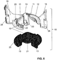
- eine perspektivische Explosionsdarstellung des Drosselelementes.
- In der
Figur 1 wird eine perspektivische Schnittansicht einer Ablaufgarnitur 1 für einen Spülkasten gezeigt. Die Ablaufgarnitur 1 dient der kontrollierten Entnahme von Spülwasser aus dem Spülkasten. - Die Ablaufgarnitur 1 umfasst im Wesentlichen einen Ventilkörper 2 mit einem Dichtungselement 4, das mit einem Ventilsitz 3 zusammenarbeitet, ein Ventilgehäuse 5, in welchem der Ventilkörper 2 bewegbar gelagert ist, und eine Halterungseinheit 6 mit einer durchgehenden Abflussöffnung 7. Die Halterungseinheit 6 dient der Verbindung des Ventilgehäuses 5 mit dem Spülkasten und durch die Abflussöffnung 7 fliesst das Spülwasser aus dem Spülkasten ab. Die Halterungseinheit 6 ragt in eine Öffnung im Spülkasten hinein oder hindurch. Der Spülkasten ist in den Figuren nicht dargestellt. Das Ventilgehäuse 5 wird in einem Lagerungsabschnitt 8 der Halterungseinheit 6 gehalten.
- Der Ventilkörper 2 ist mit dem Dichtungselement 4 vom Ventilsitz 3 entlang einer Mittelachse M von einer Ruhelage in eine Spüllage und von der Spüllage in die Ruhelage bewegbar. Für die Bewegung sind entsprechende Steuerungselemente vorhanden, welche in den Figuren nicht gezeigt sind.
- Weiter umfasst die Ablaufgarnitur 1 ein bei Bedarf einsetzbares Drosselelement 10 zur Drosselung des durch die Abflussöffnung 7 abfliessenden Spülwasserstroms. Das Drosselelement 10 wird in den
Figuren 2 bis 6 genauer dargestellt. - Die Halterungseinheit 6 umfasst in der gezeigten Ausführungsform eine Aufnahme 9 für das Drosselelement 10, wobei die Aufnahme 9 in Einbaulage der Ablaufgarnitur 1 unterhalb des Ventilsitzes 3 angeordnet ist. Das heisst, das Drosselelement 10 zur Drosselung des durch die Abflussöffnung 7 abfliessenden Spülwasserstroms ist in die Aufnahme 9 einsetzbar und von der Aufnahme 9 wiederum entfernbar.
- Die Aufnahme 9 ist in der gezeigten Ausführungsform im Inneren der Abflussöffnung 7 angeordnet. Insbesondere ist die Aufnahme 9 an der die Abflussöffnung 7 begrenzenden Seitenwand angeordnet. Das Drosselelement 10 ist also in die Abflussöffnung 7 einsetzbar und drosselt in der Abflussöffnung 7 den Spülwasserstrom. Das Drosselelement 10 steht somit in Verbindung mit der Halterungseinheit 6.
- Das Drosselelement 10 ist mit der Aufnahme 9 fest in Verbindung bringbar. Unter einer festen Verbindung wird in diesem Zusammenhang eine drehfeste Verbindung verstanden. Das heisst, das Drosselelement 10 kann in die Aufnahme 9 eingesetzt werden und ist in der Aufnahme 9 fest mit der Aufnahme 9 verbunden. Bei Nichtverwendung des Drosselelementes 10 kann das Drosselelement 10 von der Aufnahme 9 getrennt werden.
- Das Drosselelement 10 umfasst mindestens ein oberes Drosselsegment 11 mit einer Drosselfläche 12 und mindestens ein unteres Drosselsegment 13 mit einer Drosselfläche 14. In der gezeigten Ausführungsform umfasst sind zwei miteinander fest in Verbindung stehende obere Drosselsegmente 11 und zwei miteinander fest in Verbindung stehende untere Drosselsegmente 13 angeordnet. Die Zahl der Drosselsegmente 11, 13 kann auch kleiner sein. Sofern eine feinere Abstufung der Drosselwirkung erwünscht ist, kann die Zahl auch grösser sein.
- In der gezeigten Ausführungsform ist die Zahl der oberen Drosselsegmente 11 gleich der Zahl der unteren Drosselsegmente 13.
- Die unteren Drosselsegmente 13 liegen bezüglich der Mittelachse M diametral gegenüber einander. Gleiches gilt für die oberen Drosselsegmente 11.
- Die Drosselflächen 12, 14 haben die Form eines Segmentes einer Mantelfläche eines Kegels. Das heisst die Drosselflächen 12, 14 haben die Form eines Teils einer Mantelfläche eines Kegels. In der gezeigten Ausführungsform weist jede der Drosselflächen 12, 14 die Form eines Viertels einer Mantelfläche eines Kegels auf. Zusammengesetzt ergeben dabei die Mantelflächen einen gesamten Kegel.
- Die Drosselsegmente 11, 13 bzw. in der gezeigten Ausführungsform das Paar der oberen Drosselsegmente 11 und das Paar der unteren Drosselsegment 13 sind relativ zueinander verschiebbar. Die Verschiebung ist derart, dass der Querschnitt des Drosselelementes 10 und damit einhergehend auf der Querschnitt der Abflussöffnung 7 veränderbar ist.
- Das Drosselelement 10 ist mit dem mindestens einen oberen Drosselsegment 11 und dem mindestens einen unteren Drosselsegment 13 zweiteilig ausgebildet. Dabei bilden in der gezeigten Ausführungsform das Paar der oberen Drosselsegmente 11 ein erstes Teil und das Paar der unteren Drosselsegmente 13 ein zweites Teil. Das mindestens eine untere Drosselsegment 13 ist relativ zum mindestens einen oberen Drosselsegment 11 entlang einer Einstellbewegung einstellbar, hier verschwenkbar. Durch die Verschwenkung des unteren Drosselsegmentes 13 zum oberen Drosselsegment 11 sind mehrere Drosselgrade erreichbar.
- In den
Figuren 3a bis 5c werden verschiedene Ansichten von verschiedenen Stellungen des Drosselelements 10 gezeigt. - In der
Figur 3a bis 3c wird die erste Endstellung gezeigt. In der ersten Endstellung liegen die beiden oberen Drosselsegmente 11 über den beiden unteren Drosselsegmenten 13. Die beiden unteren Drosselelement 13 sind dabei in Strömungsrichtung S gesehen im Wesentlichen vollständig durch die beiden oberen Drosselsegmente 11 überdeckt. Das heisst gegen die Strömung S steht im Wesentlichen die Drosselfläche 12 der oberen Drosselsegmente 11 eine Drosselung bzw. einen Widerstand bereit. - Das untere Drosselsegment 13 lässt sich von dieser ersten Endstellung in eine zweite Endstellung verschieben.
- Eine Zwischenposition zwischen der ersten und der zweiten Endstellung wird in den
Figuren 4a bis 4c gezeigt. Dort befinden sich die beiden unteren Drosselsegmente 13 im Wesentlichen auf halber Strecke zwischen den beiden Endstellungen. Dabei ragen die unteren Drosselsegmente 13 mit ihrer Drosselfläche 14 jeweils unter den oberen Drosselsegmenten 11 hervor und stellen mit ihrer Drosselfläche 14 ebenfalls einen Widerstand bzw. eine Drosselung gegen die Strömungsrichtung S bereit. - In den Figuren 6a bis 6c wird sodann die zweite Endstellung gezeigt. Hier liegt das untere Drosselsegment 13 derart zum oberen Drosselsegment 11, dass die Drosselflächen 12, 14 von beiden Drosselsegmenten 11, 13 einen Wiederstand gegen die Strömung S bereitstellen. In dieser Endstellung bilden die beiden oberen Drosselsegmente 11 und die beiden unteren Drosselsegmente 13 eine gemeinsame Drosselfläche, welche mit Absätzen 23 im Wesentlichen der vollständig um die Mittelachse M umlaufenden Mantelfläche eines Kegels entspricht. Dies wird in der Figur 6c gezeigt.
- In allgemeiner Form kann gesagt werden, dass sich das mindestens eine untere Drosselsegment 13 relativ zum mindestens einen oberen Drosselsegment 11 von der ersten Endstellung Richtung der zweiten Endstellung derart verschieben lässt, dass der Grad der Überdeckung zwischen dem oberen und dem unteren Drosselsegment 11, 13 mit zunehmender Verschiebung abnimmt, wobei die Drosselwirkung des Drosselelementes 10 dann insgesamt zunimmt.
- Die Spülmenge bei einem Durchmesser D der Abflussöffnung 7 von 45 Millimetern ist in der ersten Endstellung, wie in den
Figuren 3a bis 3c gezeigt, vorzugsweise im Bereich von 2,3 bis 2,5 Liter pro Sekunde. Bei einer mittleren Öffnungsstellung, wie in denFiguren 4a bis 4c gezeigt, ist eine Spülmenge von 2,0 bis 2,2 Liter pro Sekunde bevorzugt. Bei der zweiten Endstellung, wie in denFiguren 5a bis 5c gezeigt wird, ist eine Spülmenge von 1,7 bis 1,9 Liter pro Sekunde bevorzugt. - Das mindestens eine untere Drosselsegment 13 steht mit dem mindestens einen oberen Drosselsegment 11 bewegbar, hier verschwenkbar, in Verbindung. Das obere Drosselsegment 11 ist ortsfest in der Abflussöffnung 7 angeordnet, während das untere Drosselsegment 13 relativ zum ortsfest angeordneten Drosselsegment 11 einstellbar ist. In der gezeigten Ausführungsform ist das untere Drosselsegment 13 an ein Drehlager 15 unterseitig am oberen Drosselsegment 11 angeordnet und über das Drehlager 15 bewegbar gelagert. Das Drehlager 15 hat in der gezeigten Ausführungsform die Gestalt eines vom oberen Drosselsegment 13 abragenden Zapfens 20, welcher in eine Öffnung 21, am unteren Drosselsegment 13 einragt.
- Des weiteren wird in der
Figur 6 gezeigt, dass eine Raststruktur 22 zwischen den Drosselsegmenten 11, 13 angeordnet ist. Die Raststruktur 22 erlaubt ein inkrementelles Einstellen der Drosselsegmente 11, 13 zueinander. - Das Drosselelement 10 steht, wie oben erläutert, mit der Aufnahme 9 in Verbindung. Hierzu weist das mindestens eine obere Drosselsegment 11 mindestens ein Lagerungsarm 16 auf. Hier sind zwei Lagerungsarme 16 angeordnet, welche sich diametral voneinander von dem Paar der oberen Drosselsegmente 11 wegerstrecken angeordnet. Die Lagerungsarme 16 greifen in mindestens eine im Bereich der Abflussöffnung 7 angeordnete Aufnahme 9 ein.
- Die der Strömung entgegengesetzte Fläche der Lagerungsarme 16 ist gerundet ausgebildet. Zudem erhöht sich der Querschnitt der Lagerungsarme zur Wandung der Abflussöffnung 7 hin.
- Endseitig weisen die Lagerungsarme 16 eine Raststruktur 24 auf, welche mit der Aufnahme 9 eine Rastverbindung eingehen. Somit kann das Drosselelement 10 über eine Rastverbindung mit der Aufnahme 9 verbunden werden. Bei der Raststruktur 24 handelt es sich in der gezeigten Variante um eine am Lagerungsarm 16 angeformte Federlasche 28, welche bei der Montage elastisch verformt wird, und an einer Anschlagsfläche 29 an der Aufnahme nach erfolgter Montage ansteht.
- Von den
Figuren 4a bis 6 kann weiter erkannt werden, dass bei jeder Stellung der Drosselsegmente 11, 13 zwischen den Drosselsegmenten 11, 13 und der Abflussöffnung 7 eine lichte Öffnung in der Gestalt eines Segmentes 17 eines Kreisrings vorhanden ist. Der Kreisring ist im Wesentlichen umlaufend um die Mittelachse M ausgebildet und wird in der gezeigten Ausführungsform nur durch eine die Lagerungsarme 16 durchtrennt. - Weiter weisen die Drosselsegmente 11, 13 gegeneinander wirkende Anschlagselemente 25 auf. Die Anschlagselemente 25 limitieren dabei die relative Bewegung zwischen den beiden Drosselsegmente 11, 13.
- Die Halterungseinheit 6 weist weiterhin seitliche Einlassöffnungen 26 auf. Die Einlassöffnungen 26 sind in Einbaulage gesehen oberhalb des Ventilsitzes 3 angeordnet und sind im Wesentlichen unterhalb des Lagerabschnittes 8, mit welchem das Ventilgehäuse 5 verbindbar ist, angeordnet. Über die Einlassöffnungen 26 strömt Spülwasser zur Abflussöffnung 7 und somit zum Drosselelement 10 zu.
- Der Lagerabschnitt 8 ist hier im Wesentlichen als zylindrische Aufnahme ausgebildet und dient der Aufnahme eines entsprechenden zylindrischen Abschnittes des Ventilgehäuses 5.
- Aussenseitig umfasst die Halterungseinheit 6 einen Kontaktabschnitt 27. Der Kontaktabschnitt 27 dient zum Einbau der Halterungseinheit 6 in einen Spülkasten. In der gezeigten Ausführungsform ist der Kontaktabschnitt 27 unterhalb des Ventilsitzes angeordnet.
BEZUGSZEICHENLISTE 1 Ablaufgarnitur 29 Anschlagsfläche 2 Ventilkörper M Mittelachse 3 Ventilsitz S Strömungsrichtung 4 Dichtungselement D Durchmesser 5 Ventilgehäuse 6 Halterungseinheit 7 Abflussöffnung 8 Lagerabschnitt 9 Aufnahme 10 Drosselelement 11 oberes Drosselsegment 12 Drosselfläche 13 unteres Drosselsegment 14 Drosselfläche 15 Drehlager 16 Lagerungsarm 17 Kreisringsegment 18 Rastverbindung 19 Kegelspitze 20 Zapfen 21 Öffnung 22 Raststruktur 23 Absatz 24 Raststruktur 25 Anschlagselemente 26 Einlassöffnung 27 Kontaktabschnitt 28 Federlasche
Claims (15)
- Ablaufgarnitur (1) für einen Spülkasten, umfassend
einen Ventilkörper (2) mit einem mit einem Ventilsitz (3) zusammenarbeitenden Dichtungselement (4), wobei der Ventilkörper (2) mit dem Dichtungselement (4) vom Ventilsitz (3) entlang einer Mittelachse (M) von einer Ruhelage in Spüllage und von der Spüllage in die Ruhelage bewegbar ist,
ein Ventilgehäuse (5), in welchem der Ventilkörper (2) bewegbar gelagert ist, und eine Halterungseinheit (6) mit einer durchgehenden Abflussöffnung (7), wobei sich der besagte Ventilsitz (3) um die Abflussöffnung (7) herum erstreckt und wobei in Einbaulage gesehen oberhalb des Ventilsitzes (3) die Halterungseinheit (6) einen Lagerabschnitt (8) zur Lagerung des Ventilgehäuses (5) aufweist,
wobei die Ablaufgarnitur (1) weiter ein einstellbares Drosselelement (10) zur einstellbaren Drosselung des durch die Abflussöffnung (7) abfliessenden Spülwasserstroms umfasst, dadurch gekennzeichnet,
dass das Drosselelement (10) mindestens ein oberes Drosselsegment (11) mit einer Drosselfläche (12), die die Form eines Segmentes einer Mantelfläche eines Kegels hat, und mindestens ein unteres Drosselsegment (13) mit einer Drosselfläche (14), die die Form eines Segmentes einer Mantelfläche eines Kegels hat, aufweist, wobei die Drosselsegmente (11, 13) relativ zueinander verschiebbar sind, derart, dass der Querschnitt des Drosselelementes (10) bzw. der Abflussöffnung (7) veränderbar ist. - Ablaufgarnitur (1) nach Anspruch 1, dadurch gekennzeichnet, dass das untere Drosselsegment (13) in einer ersten Endstellung in Strömungsrichtung (S) gesehen im Wesentlichen vollständig durch das obere Drosselsegment (11) überdeckt wird und dass sich das untere Drosselsegment (13) in Richtung einer zweiten Endstellung derart verschieben lässt, dass der Grad der Überdeckung der beiden Drosselsegmente (11, 13) mit zunehmender Verschiebung abnimmt, wobei die Drosselwirkung des Drosselelementes (10) insgesamt zunimmt.
- Ablaufgarnitur (1) nach Anspruch 2, dadurch gekennzeichnet, dass in der zweiten Endstellung die Drosselsegmente (11, 13) derart zueinander liegen, dass ein im Wesentlichen vollständig um die Mittelachse (M) umlaufender Kegel resultiert.
- Ablaufgarnitur (1) nach Anspruch 2 oder 3, dadurch gekennzeichnet, dass die Spülmenge bei einem Durchmesser (D) der Abflussöffnung (7) von 45 Millimetern in der ersten Endstellung im Bereich von 2.3 bis 2.5 Liter pro Sekunde ist und bei einer mittleren Öffnungsstellung bei 2.0 bis 2.2 Liter pro Sekunde ist und bei der zweiten Endstellung bei 1.7 bis 1.9 Liter pro Sekunde ist.
- Ablaufgarnitur (1) nach einem der vorhergehenden Ansprüche, dadurch gekennzeichnet, dass die Zahl der oberen Drosselsegmente (11) gleich der Zahl der unteren Drosselsegmente (13) ist.
- Ablaufgarnitur (1) nach einem der vorhergehenden Ansprüche, dadurch gekennzeichnet, dass jeweils die oberen Drosselsegemente (11) miteinander verbunden sind und daher miteinander verschwenkbar sind; und/oder dass jeweils die unteren Drosselsegmente (13) miteinander verbunden sind und daher miteinander verschwenkbar sind.
- Ablaufgarnitur (1) nach einem der vorhergehenden Ansprüche, dadurch gekennzeichnet, dass das untere Drosselsegment (13) mit dem oberen Drosselsegment (11) bewegbar, insbesondere verschwenkbar, in Verbindung steht, wobei eines der Drosselsegmente (11, 13) ortsfest in der Abflussöffnung angeordnet ist, während das andere der Drosselsegmente (13, 11) relativ zum orstfest angeordneten Drosselsegment (11, 13) einstellbar ist.
- Ablaufgarnitur (1) nach einem der vorhergehenden Ansprüche, dadurch gekennzeichnet, dass das untere Drosselsegment (13) an einem Drehlager (15), unterseitig am oberen Drosselelement (11) angeordnet ist und über das Drehlager (15) bewegbar gelagert ist.
- Ablaufgarnitur (1) nach einem der vorhergehenden Ansprüche, dadurch gekennzeichnet, dass die beiden Drosselsegmente (11, 13) mittig in der Abflussöffnung (7) liegen.
- Ablaufgarnitur (1) nach einem der vorhergehenden Ansprüche, dadurch gekennzeichnet, dass bei jeder Stellung der Drosselsegmente (11, 12) zwischen den Drosselsegmenten (11, 12) und der Abflussöffnung (7) eine lichte Öffnung in der Gestalt eines Segmentes (17) eines Kreisrings vorhanden ist.
- Ablaufgarnitur (1) nach einem der vorhergehenden Ansprüche, dadurch gekennzeichnet, dass das mindestens eine obere Drosselsegment (11) mindestens ein Lagerungsarm (16) aufweist, welcher in mindestens eine im Bereich der Abflussöffnung (7) angeordneten Aufnahme (9) eingreift, wobei das Drosselelement (10), insbesondere bei Bedarf, in die Aufnahme (9) einsetzbar ist.
- Ablaufgarnitur (1) nach Anspruch 11, dadurch gekennzeichnet, dass die Verbindung zwischen dem mindestens einen Lagerungsarm (16) und der Aufnahme (9) eine Rastverbindung (18) ist.
- Ablaufgarnitur (1) nach einem der Ansprüche 10 bis 12, dadurch gekennzeichnet, dass das Segment (17) des Kreisrings abgesehen von den Lagerarmen (16) sich vollständig um die Mittelachse (M) herum erstreckt.
- Ablaufgarnitur (1) nach einem der vorhergehenden Ansprüche, dadurch gekennzeichnet, dass der Kegelwinkel (α) des Kegels grösser als 90° ist; und/oder dass der Kegel an der Kegelspitze (19) gerundet oder abgeflacht oder spitz ausgebildet ist.
- Spülkastenanordnung umfassend einer Ablaufgarnitur (1) nach einem der vorhergehenden Ansprüche und ein Spülkasten mit einer Auslauföffnung, wobei die Halterungseinheit (6) sich in die Auslauföffnung hinein erstreckt.
Priority Applications (5)
| Application Number | Priority Date | Filing Date | Title |
|---|---|---|---|
| EP17173446.0A EP3208393B1 (de) | 2017-05-30 | 2017-05-30 | Spülstromdrossel |
| PL17173446T PL3208393T3 (pl) | 2017-05-30 | 2017-05-30 | Dławik strumienia spłukującego |
| PT171734460T PT3208393T (pt) | 2017-05-30 | 2017-05-30 | Guarnição de descarga para autoclismos |
| DK17173446.0T DK3208393T3 (da) | 2017-05-30 | 2017-05-30 | Reduktionsventil til skyllevand |
| CN201810430994.9A CN108980386A (zh) | 2017-05-30 | 2018-05-08 | 冲洗水流节流器 |
Applications Claiming Priority (1)
| Application Number | Priority Date | Filing Date | Title |
|---|---|---|---|
| EP17173446.0A EP3208393B1 (de) | 2017-05-30 | 2017-05-30 | Spülstromdrossel |
Publications (2)
| Publication Number | Publication Date |
|---|---|
| EP3208393A1 true EP3208393A1 (de) | 2017-08-23 |
| EP3208393B1 EP3208393B1 (de) | 2019-10-23 |
Family
ID=58873673
Family Applications (1)
| Application Number | Title | Priority Date | Filing Date |
|---|---|---|---|
| EP17173446.0A Active EP3208393B1 (de) | 2017-05-30 | 2017-05-30 | Spülstromdrossel |
Country Status (5)
| Country | Link |
|---|---|
| EP (1) | EP3208393B1 (de) |
| CN (1) | CN108980386A (de) |
| DK (1) | DK3208393T3 (de) |
| PL (1) | PL3208393T3 (de) |
| PT (1) | PT3208393T (de) |
Families Citing this family (1)
| Publication number | Priority date | Publication date | Assignee | Title |
|---|---|---|---|---|
| DE102019003301A1 (de) * | 2019-05-10 | 2020-11-12 | Grohe Ag | Einhebel-Kartusche für eine Sanitärarmatur |
Citations (3)
| Publication number | Priority date | Publication date | Assignee | Title |
|---|---|---|---|---|
| DE202016101412U1 (de) | 2015-08-05 | 2016-03-30 | Mepa-Pauli Und Menden Gmbh | Spülkastenanordnung mit veränderbarem Spülstrom |
| WO2016105295A1 (en) * | 2014-12-26 | 2016-06-30 | ECZACIBAŞI YAPI GEREÇLERİ SANAYİ VE TİCARET ANONİM ŞİRKETİ ANONIM SIRKETi | Flushing apparatus for closet bowl with flow rate adjuster |
| WO2017036877A1 (de) * | 2015-09-03 | 2017-03-09 | Villeroy & Boch Ag | Ablaufventil für wc-spüleinheit, drossel für ablaufventil, spülkasten mit ablaufventil und verfahren zu dessen montage |
-
2017
- 2017-05-30 DK DK17173446.0T patent/DK3208393T3/da active
- 2017-05-30 PT PT171734460T patent/PT3208393T/pt unknown
- 2017-05-30 PL PL17173446T patent/PL3208393T3/pl unknown
- 2017-05-30 EP EP17173446.0A patent/EP3208393B1/de active Active
-
2018
- 2018-05-08 CN CN201810430994.9A patent/CN108980386A/zh active Pending
Patent Citations (3)
| Publication number | Priority date | Publication date | Assignee | Title |
|---|---|---|---|---|
| WO2016105295A1 (en) * | 2014-12-26 | 2016-06-30 | ECZACIBAŞI YAPI GEREÇLERİ SANAYİ VE TİCARET ANONİM ŞİRKETİ ANONIM SIRKETi | Flushing apparatus for closet bowl with flow rate adjuster |
| DE202016101412U1 (de) | 2015-08-05 | 2016-03-30 | Mepa-Pauli Und Menden Gmbh | Spülkastenanordnung mit veränderbarem Spülstrom |
| WO2017036877A1 (de) * | 2015-09-03 | 2017-03-09 | Villeroy & Boch Ag | Ablaufventil für wc-spüleinheit, drossel für ablaufventil, spülkasten mit ablaufventil und verfahren zu dessen montage |
Also Published As
| Publication number | Publication date |
|---|---|
| PL3208393T3 (pl) | 2020-04-30 |
| PT3208393T (pt) | 2019-12-16 |
| DK3208393T3 (da) | 2020-01-27 |
| CN108980386A (zh) | 2018-12-11 |
| EP3208393B1 (de) | 2019-10-23 |
Similar Documents
| Publication | Publication Date | Title |
|---|---|---|
| EP2536886B1 (de) | Sanitäres einbauelement für wasserauslauf | |
| EP2287409B1 (de) | Sanitärer Wasserauslauf mit verschwenkbarer Strömungsführung | |
| DE3150100C2 (de) | Schwimmergesteuertes Wasserzulaufventil | |
| EP3213803B1 (de) | Filter-anordnung | |
| EP0182327B1 (de) | Vorrichtung zur drosselnden Durchflussbegrenzung in Wasser-Armaturen | |
| EP0382040B1 (de) | Sanitäres Mischventil | |
| DE102016116550B4 (de) | Drehschieberventil mit kompaktem Dichtelement | |
| DE2904131C3 (de) | Mischventil für Flüssigkeiten | |
| EP0073855B1 (de) | Absperrventil für Fluide | |
| EP3730705B1 (de) | Sanitärventil | |
| EP3276095B1 (de) | Vorrichtung zum drosseln des spülstroms aus einem sanitären spülkasten, ablaufventil und sanitärer spülkasten mit einer solchen vorrichtung | |
| EP3208393B1 (de) | Spülstromdrossel | |
| EP3344820B1 (de) | Ablaufventil für wc-spüleinheit, spülkasten mit ablaufventil und verfahren zu dessen montage | |
| DE19901654A1 (de) | Eckventil mit Rosettengriff | |
| DE2558569A1 (de) | Vier-weg-mischventil | |
| EP3321435A1 (de) | Ablaufgarnituranordnung | |
| EP3647504B1 (de) | Sanitärartikelanordnung | |
| DE2050025B2 (de) | Eingriff Mischbatterie | |
| EP3228766B1 (de) | Leitungsstückanordnung | |
| EP3992377A1 (de) | Strahlreglereinsatz mit rückverkeimungsschutz | |
| DE2614063B2 (de) | Mischventil der huelsenbauart | |
| DE69212031T2 (de) | Pneumatisches Verbindungssystem mit einem verbesserten Luftregelventil | |
| EP0256204B1 (de) | Membranventil | |
| EP1180624A2 (de) | Regulierventil mit Voreinstellung | |
| DE2150635C3 (de) |
Legal Events
| Date | Code | Title | Description |
|---|---|---|---|
| PUAI | Public reference made under article 153(3) epc to a published international application that has entered the european phase |
Free format text: ORIGINAL CODE: 0009012 |
|
| STAA | Information on the status of an ep patent application or granted ep patent |
Free format text: STATUS: THE APPLICATION HAS BEEN PUBLISHED |
|
| AK | Designated contracting states |
Kind code of ref document: A1 Designated state(s): AL AT BE BG CH CY CZ DE DK EE ES FI FR GB GR HR HU IE IS IT LI LT LU LV MC MK MT NL NO PL PT RO RS SE SI SK SM TR |
|
| AX | Request for extension of the european patent |
Extension state: BA ME |
|
| STAA | Information on the status of an ep patent application or granted ep patent |
Free format text: STATUS: REQUEST FOR EXAMINATION WAS MADE |
|
| 17P | Request for examination filed |
Effective date: 20180111 |
|
| RBV | Designated contracting states (corrected) |
Designated state(s): AL AT BE BG CH CY CZ DE DK EE ES FI FR GB GR HR HU IE IS IT LI LT LU LV MC MK MT NL NO PL PT RO RS SE SI SK SM TR |
|
| GRAP | Despatch of communication of intention to grant a patent |
Free format text: ORIGINAL CODE: EPIDOSNIGR1 |
|
| STAA | Information on the status of an ep patent application or granted ep patent |
Free format text: STATUS: GRANT OF PATENT IS INTENDED |
|
| RIC1 | Information provided on ipc code assigned before grant |
Ipc: E03D 9/16 20060101AFI20190315BHEP Ipc: E03D 1/34 20060101ALI20190315BHEP |
|
| INTG | Intention to grant announced |
Effective date: 20190404 |
|
| GRAJ | Information related to disapproval of communication of intention to grant by the applicant or resumption of examination proceedings by the epo deleted |
Free format text: ORIGINAL CODE: EPIDOSDIGR1 |
|
| STAA | Information on the status of an ep patent application or granted ep patent |
Free format text: STATUS: REQUEST FOR EXAMINATION WAS MADE |
|
| INTC | Intention to grant announced (deleted) | ||
| GRAR | Information related to intention to grant a patent recorded |
Free format text: ORIGINAL CODE: EPIDOSNIGR71 |
|
| GRAS | Grant fee paid |
Free format text: ORIGINAL CODE: EPIDOSNIGR3 |
|
| STAA | Information on the status of an ep patent application or granted ep patent |
Free format text: STATUS: GRANT OF PATENT IS INTENDED |
|
| GRAA | (expected) grant |
Free format text: ORIGINAL CODE: 0009210 |
|
| STAA | Information on the status of an ep patent application or granted ep patent |
Free format text: STATUS: THE PATENT HAS BEEN GRANTED |
|
| AK | Designated contracting states |
Kind code of ref document: B1 Designated state(s): AL AT BE BG CH CY CZ DE DK EE ES FI FR GB GR HR HU IE IS IT LI LT LU LV MC MK MT NL NO PL PT RO RS SE SI SK SM TR |
|
| INTG | Intention to grant announced |
Effective date: 20190916 |
|
| REG | Reference to a national code |
Ref country code: GB Ref legal event code: FG4D Free format text: NOT ENGLISH |
|
| REG | Reference to a national code |
Ref country code: CH Ref legal event code: EP |
|
| REG | Reference to a national code |
Ref country code: IE Ref legal event code: FG4D Free format text: LANGUAGE OF EP DOCUMENT: GERMAN |
|
| REG | Reference to a national code |
Ref country code: DE Ref legal event code: R096 Ref document number: 502017002627 Country of ref document: DE |
|
| REG | Reference to a national code |
Ref country code: AT Ref legal event code: REF Ref document number: 1193765 Country of ref document: AT Kind code of ref document: T Effective date: 20191115 |
|
| REG | Reference to a national code |
Ref country code: CH Ref legal event code: NV Representative=s name: ISLER AND PEDRAZZINI AG, CH |
|
| REG | Reference to a national code |
Ref country code: PT Ref legal event code: SC4A Ref document number: 3208393 Country of ref document: PT Date of ref document: 20191216 Kind code of ref document: T Free format text: AVAILABILITY OF NATIONAL TRANSLATION Effective date: 20191204 |
|
| REG | Reference to a national code |
Ref country code: DK Ref legal event code: T3 Effective date: 20200124 |
|
| REG | Reference to a national code |
Ref country code: NL Ref legal event code: FP |
|
| REG | Reference to a national code |
Ref country code: LT Ref legal event code: MG4D |
|
| PG25 | Lapsed in a contracting state [announced via postgrant information from national office to epo] |
Ref country code: NO Free format text: LAPSE BECAUSE OF FAILURE TO SUBMIT A TRANSLATION OF THE DESCRIPTION OR TO PAY THE FEE WITHIN THE PRESCRIBED TIME-LIMIT Effective date: 20200123 Ref country code: FI Free format text: LAPSE BECAUSE OF FAILURE TO SUBMIT A TRANSLATION OF THE DESCRIPTION OR TO PAY THE FEE WITHIN THE PRESCRIBED TIME-LIMIT Effective date: 20191023 Ref country code: BG Free format text: LAPSE BECAUSE OF FAILURE TO SUBMIT A TRANSLATION OF THE DESCRIPTION OR TO PAY THE FEE WITHIN THE PRESCRIBED TIME-LIMIT Effective date: 20200123 Ref country code: LV Free format text: LAPSE BECAUSE OF FAILURE TO SUBMIT A TRANSLATION OF THE DESCRIPTION OR TO PAY THE FEE WITHIN THE PRESCRIBED TIME-LIMIT Effective date: 20191023 Ref country code: SE Free format text: LAPSE BECAUSE OF FAILURE TO SUBMIT A TRANSLATION OF THE DESCRIPTION OR TO PAY THE FEE WITHIN THE PRESCRIBED TIME-LIMIT Effective date: 20191023 Ref country code: GR Free format text: LAPSE BECAUSE OF FAILURE TO SUBMIT A TRANSLATION OF THE DESCRIPTION OR TO PAY THE FEE WITHIN THE PRESCRIBED TIME-LIMIT Effective date: 20200124 Ref country code: LT Free format text: LAPSE BECAUSE OF FAILURE TO SUBMIT A TRANSLATION OF THE DESCRIPTION OR TO PAY THE FEE WITHIN THE PRESCRIBED TIME-LIMIT Effective date: 20191023 |
|
| PG25 | Lapsed in a contracting state [announced via postgrant information from national office to epo] |
Ref country code: IS Free format text: LAPSE BECAUSE OF FAILURE TO SUBMIT A TRANSLATION OF THE DESCRIPTION OR TO PAY THE FEE WITHIN THE PRESCRIBED TIME-LIMIT Effective date: 20200224 Ref country code: HR Free format text: LAPSE BECAUSE OF FAILURE TO SUBMIT A TRANSLATION OF THE DESCRIPTION OR TO PAY THE FEE WITHIN THE PRESCRIBED TIME-LIMIT Effective date: 20191023 Ref country code: RS Free format text: LAPSE BECAUSE OF FAILURE TO SUBMIT A TRANSLATION OF THE DESCRIPTION OR TO PAY THE FEE WITHIN THE PRESCRIBED TIME-LIMIT Effective date: 20191023 |
|
| PG25 | Lapsed in a contracting state [announced via postgrant information from national office to epo] |
Ref country code: AL Free format text: LAPSE BECAUSE OF FAILURE TO SUBMIT A TRANSLATION OF THE DESCRIPTION OR TO PAY THE FEE WITHIN THE PRESCRIBED TIME-LIMIT Effective date: 20191023 |
|
| REG | Reference to a national code |
Ref country code: DE Ref legal event code: R097 Ref document number: 502017002627 Country of ref document: DE |
|
| PG2D | Information on lapse in contracting state deleted |
Ref country code: IS |
|
| PG25 | Lapsed in a contracting state [announced via postgrant information from national office to epo] |
Ref country code: ES Free format text: LAPSE BECAUSE OF FAILURE TO SUBMIT A TRANSLATION OF THE DESCRIPTION OR TO PAY THE FEE WITHIN THE PRESCRIBED TIME-LIMIT Effective date: 20191023 Ref country code: EE Free format text: LAPSE BECAUSE OF FAILURE TO SUBMIT A TRANSLATION OF THE DESCRIPTION OR TO PAY THE FEE WITHIN THE PRESCRIBED TIME-LIMIT Effective date: 20191023 Ref country code: RO Free format text: LAPSE BECAUSE OF FAILURE TO SUBMIT A TRANSLATION OF THE DESCRIPTION OR TO PAY THE FEE WITHIN THE PRESCRIBED TIME-LIMIT Effective date: 20191023 Ref country code: CZ Free format text: LAPSE BECAUSE OF FAILURE TO SUBMIT A TRANSLATION OF THE DESCRIPTION OR TO PAY THE FEE WITHIN THE PRESCRIBED TIME-LIMIT Effective date: 20191023 Ref country code: IS Free format text: LAPSE BECAUSE OF FAILURE TO SUBMIT A TRANSLATION OF THE DESCRIPTION OR TO PAY THE FEE WITHIN THE PRESCRIBED TIME-LIMIT Effective date: 20200223 |
|
| PLBE | No opposition filed within time limit |
Free format text: ORIGINAL CODE: 0009261 |
|
| STAA | Information on the status of an ep patent application or granted ep patent |
Free format text: STATUS: NO OPPOSITION FILED WITHIN TIME LIMIT |
|
| PG25 | Lapsed in a contracting state [announced via postgrant information from national office to epo] |
Ref country code: SM Free format text: LAPSE BECAUSE OF FAILURE TO SUBMIT A TRANSLATION OF THE DESCRIPTION OR TO PAY THE FEE WITHIN THE PRESCRIBED TIME-LIMIT Effective date: 20191023 Ref country code: SK Free format text: LAPSE BECAUSE OF FAILURE TO SUBMIT A TRANSLATION OF THE DESCRIPTION OR TO PAY THE FEE WITHIN THE PRESCRIBED TIME-LIMIT Effective date: 20191023 |
|
| 26N | No opposition filed |
Effective date: 20200724 |
|
| PG25 | Lapsed in a contracting state [announced via postgrant information from national office to epo] |
Ref country code: SI Free format text: LAPSE BECAUSE OF FAILURE TO SUBMIT A TRANSLATION OF THE DESCRIPTION OR TO PAY THE FEE WITHIN THE PRESCRIBED TIME-LIMIT Effective date: 20191023 |
|
| PG25 | Lapsed in a contracting state [announced via postgrant information from national office to epo] |
Ref country code: MC Free format text: LAPSE BECAUSE OF FAILURE TO SUBMIT A TRANSLATION OF THE DESCRIPTION OR TO PAY THE FEE WITHIN THE PRESCRIBED TIME-LIMIT Effective date: 20191023 |
|
| PG25 | Lapsed in a contracting state [announced via postgrant information from national office to epo] |
Ref country code: LU Free format text: LAPSE BECAUSE OF NON-PAYMENT OF DUE FEES Effective date: 20200530 |
|
| PG25 | Lapsed in a contracting state [announced via postgrant information from national office to epo] |
Ref country code: IE Free format text: LAPSE BECAUSE OF NON-PAYMENT OF DUE FEES Effective date: 20200530 |
|
| PG25 | Lapsed in a contracting state [announced via postgrant information from national office to epo] |
Ref country code: MT Free format text: LAPSE BECAUSE OF FAILURE TO SUBMIT A TRANSLATION OF THE DESCRIPTION OR TO PAY THE FEE WITHIN THE PRESCRIBED TIME-LIMIT Effective date: 20191023 Ref country code: CY Free format text: LAPSE BECAUSE OF FAILURE TO SUBMIT A TRANSLATION OF THE DESCRIPTION OR TO PAY THE FEE WITHIN THE PRESCRIBED TIME-LIMIT Effective date: 20191023 |
|
| PG25 | Lapsed in a contracting state [announced via postgrant information from national office to epo] |
Ref country code: MK Free format text: LAPSE BECAUSE OF FAILURE TO SUBMIT A TRANSLATION OF THE DESCRIPTION OR TO PAY THE FEE WITHIN THE PRESCRIBED TIME-LIMIT Effective date: 20191023 |
|
| P01 | Opt-out of the competence of the unified patent court (upc) registered |
Effective date: 20230516 |
|
| REG | Reference to a national code |
Ref country code: NL Ref legal event code: PD Owner name: GEBERIT HOLDING AG; CH Free format text: DETAILS ASSIGNMENT: CHANGE OF OWNER(S), MERGE; FORMER OWNER NAME: GEBERIT INTERNATIONAL AG Effective date: 20240604 Ref country code: NL Ref legal event code: HC Owner name: GEBERIT INTERNATIONAL AG; CH Free format text: DETAILS ASSIGNMENT: CHANGE OF OWNER(S), CHANGE OF OWNER(S) NAME; FORMER OWNER NAME: GEBERIT HOLDING AG Effective date: 20240604 |
|
| REG | Reference to a national code |
Ref country code: BE Ref legal event code: PD Owner name: GEBERIT HOLDING AG; CH Free format text: DETAILS ASSIGNMENT: CHANGE OF OWNER(S), MERGE; FORMER OWNER NAME: GEBERIT INTERNATIONAL AG Effective date: 20240528 Ref country code: BE Ref legal event code: HC Owner name: GEBERIT INTERNATIONAL AG; CH Free format text: DETAILS ASSIGNMENT: CHANGE OF OWNER(S), CHANGE OF OWNER(S) NAME; FORMER OWNER NAME: GEBERIT HOLDING AG Effective date: 20240528 |
|
| REG | Reference to a national code |
Ref country code: AT Ref legal event code: PC Ref document number: 1193765 Country of ref document: AT Kind code of ref document: T Owner name: GEBERIT INTERNATIONAL AG, CH Effective date: 20241118 |
|
| PGFP | Annual fee paid to national office [announced via postgrant information from national office to epo] |
Ref country code: NL Payment date: 20250521 Year of fee payment: 9 |
|
| PGFP | Annual fee paid to national office [announced via postgrant information from national office to epo] |
Ref country code: PL Payment date: 20250425 Year of fee payment: 9 Ref country code: DE Payment date: 20250521 Year of fee payment: 9 |
|
| PGFP | Annual fee paid to national office [announced via postgrant information from national office to epo] |
Ref country code: GB Payment date: 20250521 Year of fee payment: 9 Ref country code: DK Payment date: 20250526 Year of fee payment: 9 |
|
| PGFP | Annual fee paid to national office [announced via postgrant information from national office to epo] |
Ref country code: BE Payment date: 20250521 Year of fee payment: 9 Ref country code: IT Payment date: 20250521 Year of fee payment: 9 |
|
| PGFP | Annual fee paid to national office [announced via postgrant information from national office to epo] |
Ref country code: PT Payment date: 20250522 Year of fee payment: 9 |
|
| PGFP | Annual fee paid to national office [announced via postgrant information from national office to epo] |
Ref country code: FR Payment date: 20250528 Year of fee payment: 9 |
|
| PGFP | Annual fee paid to national office [announced via postgrant information from national office to epo] |
Ref country code: CH Payment date: 20250601 Year of fee payment: 9 |
|
| PGFP | Annual fee paid to national office [announced via postgrant information from national office to epo] |
Ref country code: AT Payment date: 20250522 Year of fee payment: 9 |
|
| PGFP | Annual fee paid to national office [announced via postgrant information from national office to epo] |
Ref country code: TR Payment date: 20250526 Year of fee payment: 9 |