EP3208367A1 - Yarn cooler - Google Patents
Yarn cooler Download PDFInfo
- Publication number
- EP3208367A1 EP3208367A1 EP17154570.0A EP17154570A EP3208367A1 EP 3208367 A1 EP3208367 A1 EP 3208367A1 EP 17154570 A EP17154570 A EP 17154570A EP 3208367 A1 EP3208367 A1 EP 3208367A1
- Authority
- EP
- European Patent Office
- Prior art keywords
- passage
- yarn
- enlarged portion
- bulging
- flow adjustment
- Prior art date
- Legal status (The legal status is an assumption and is not a legal conclusion. Google has not performed a legal analysis and makes no representation as to the accuracy of the status listed.)
- Granted
Links
Images




Classifications
-
- D—TEXTILES; PAPER
- D01—NATURAL OR MAN-MADE THREADS OR FIBRES; SPINNING
- D01D—MECHANICAL METHODS OR APPARATUS IN THE MANUFACTURE OF ARTIFICIAL FILAMENTS, THREADS, FIBRES, BRISTLES OR RIBBONS
- D01D5/00—Formation of filaments, threads, or the like
- D01D5/08—Melt spinning methods
- D01D5/088—Cooling filaments, threads or the like, leaving the spinnerettes
-
- D—TEXTILES; PAPER
- D01—NATURAL OR MAN-MADE THREADS OR FIBRES; SPINNING
- D01D—MECHANICAL METHODS OR APPARATUS IN THE MANUFACTURE OF ARTIFICIAL FILAMENTS, THREADS, FIBRES, BRISTLES OR RIBBONS
- D01D5/00—Formation of filaments, threads, or the like
- D01D5/08—Melt spinning methods
- D01D5/088—Cooling filaments, threads or the like, leaving the spinnerettes
- D01D5/092—Cooling filaments, threads or the like, leaving the spinnerettes in shafts or chimneys
Definitions
- the present invention relates to a yarn cooler configured to cool yarns spun out from a spinning device.
- a yarn cooler configured to cool yarns spun out from a spinning device.
- a yarn cooler generally includes: a yarn cooling unit configured to cool a spun out yarn by air blown to the yarn; and a duct through which cooling air is supplied to the yarn cooling unit.
- the duct of such a yarn cooler has a portion in which the width of a passage in the duct increases toward the yarn cooling unit.
- a portion is referred to as a passage-enlarged portion.
- air tends to flow in the following manner: the flow rate of air is the highest at a central part of this portion in the width direction of the passage; and the farther the airflow is from the central part, the lower the flow rate is.
- This flow-rate distribution may cause unevenness in cooling of the yarn in the yarn cooling unit. To deal with this, it is desirable to equalize the flow rates as uniform as possible with respect to the width direction by adjusting airflows in the passage-enlarged portion.
- Patent Literature 2 Japanese Unexamined Patent Publication No. H08-201215 discloses the arrangement in which partition plates are arranged radially in a passage-enlarged portion (enlarged duct portion) of a duct. In this arrangement, airflow in the passage-enlarged portion is adjusted by the partition plates.
- upstream end portions of the partition plates which ends are located upstream in a flow path, are aligned in a straight line in the width direction of the passage. That is, the upstream end portions of the partition plates are at the same level.
- Patent Literature 3 Japanese Patent No. 4829002 discloses the arrangement in which wind direction changing members are arranged though these members are located downstream of a passage-enlarged portion.
- an upstream end portion of each wind direction changing member has a bulging shape.
- the end portions of the wind direction changing members are at the same level and aligned in a straight line in the width direction, also in Patent Literature 3.
- Patent Literatures 2 and 3 mentioned above each discloses the duct provided with the members adjusting airflow in the passage-enlarged portion.
- the upstream end portions of these flow adjustment members (the end portions closer to an entrance portion of the passage-enlarged portion) are aligned in a straight line in the width direction of the passage.
- the present inventors found that, in the above arrangement where the end portions of the flow adjustment members are arranged linearly, a disturbance of airflow is more likely to occur, and there is a high degree of dispersion in flow rates in the passage-enlarged portion.
- An object of the present invention is to suppress a disturbance of flow in a passage-enlarged portion and to minimize the degree of dispersion in flow rates with respect to the width direction of a passage in the passage-enlarged portion.
- a yarn cooler includes: at least one yarn cooling unit configured to cool a yarn spun out from a spinning device by gas blown to the yarn; and a gas supply unit having a passage through which gas is supplied to the yarn cooling unit, the gas supply unit including: a sector-like passage-enlarged portion in which the width of the passage increases toward the yarn cooling unit; and a plurality of flow adjustment plates arranged in the passage-enlarged portion so as to radially fan out toward an exit portion of the passage-enlarged portion, each of the flow adjustment plates including a bulging portion at its end portion closer to an entrance portion of the passage-enlarged portion, the bulging portions being arranged in an arc protruding toward the exit portion of the passage-enlarged portion.
- each flow adjustment plate has the bulging portion at the entrance-side end portion of the plate.
- the bulging portions of the flow adjustment plates are arranged linearly in the width direction of the passage-enlarged portion, the disturbance is more likely to occur because gas having entered the passage-enlarged portion collides with a row of the bulging portions aligned at smaller intervals.
- the bulging portions are arranged in an arc protruding toward the exit portion of the passage-enlarged portion in the present invention. That is, the entrance portion of the passage-enlarged portion has a space partially surrounded by the bulging portions.
- gas having entered the passage-enlarged portion first flowing through the above space, and then, smoothly enters the gaps between the flow adjustment plates while spreading radially. Because of this, the disturbance of the flow of gas is less likely to occur.
- the yarn cooler of the first aspect is arranged such that each bulging portion has a curved surface.
- each bulging portion is curved. This makes it easier for gas to flow along the surfaces of the bulging portions, and reduces the possibility that the flow deviates from the flow adjustment plates.
- the yarn cooler of the second aspect is arranged such that each bulging portion has a circular cross sectional shape.
- each bulging portion is circular. Such bulging portions are processed easily, and advantageous in terms of cost.
- the yarn cooler of the third aspect is arranged such that a diameter of each bulging portion is not less than 5 mm and not more than 16 mm.
- each bulging portion is too small, the effect of reducing the possibility of deviation from the flow adjustment plates is smaller. To the contrary, if each bulging portion is too large, there is a large passage resistance, which makes it difficult for gas to enter the gaps between the flow adjustment plates. For this reason, it is preferable that the diameter of each bulging portion is not less than 5 mm and not more than 16 mm.
- the yarn cooler of the first aspect is arranged such that each bulging portion has a triangular cross sectional shape which widens toward the exit portion of the passage-enlarged portion.
- each bulging portion which widens toward the exit portion prevents the flow of gas having contacted the end portion of each flow adjustment plate from greatly deviating from the flow adjustment plate and makes it easier for gas to flow along the flow adjustment plate.
- the yarn cooler of any one of the first to fifth aspects is arranged such that an intersection of extension lines of two side walls of the sector-like passage-enlarged portion matches a center point of the arc along which the bulging portions are arranged.
- the intersection of the extension lines of the two side walls of the sector-like passage-enlarged portion matches the center point of the arc along which the bulging portions are arranged. Because of this, radially fanning out streamlines of gas flowing while spreading in the passage-enlarged portion are orthogonal to the arc along which the bulging portions are arranged. This makes it easier for gas to enter the gaps between the bulging portions.
- the yarn cooler of any one of the first to sixth aspects is arranged such that an angle between each two adjacent plates of the flow adjustment plates is not less than 6 degrees and not more than 16 degrees.
- the angle between each two adjacent flow adjustment plates is not less than 6 degrees and not more than 16 degrees.
- the yarn cooler of any one of the first to seventh aspects is arranged such that the at least one yarn cooling unit includes a plurality of yarn cooling units, the yarn cooler further includes a box accommodating the yarn cooling units, the yarn cooling units are arranged in a predetermined direction in the box, and the exit portion of the passage-enlarged portion is coupled to a side portion of the box that is located on a side of the box in a direction orthogonal to the predetermined direction.
- the exit portion of the passage-enlarged portion is coupled to a side portion of the box accommodating the yarn cooling units, which side portion is on a side of the box in the direction orthogonal to the arrangement direction of the yarn cooling units. If the degree of dispersion in the flow rates with respect to the width direction is high at the exit portion of the passage-enlarged portion, there is caused a difference in the cooling capability among the yarn cooling units. Adoption of the arrangement of the flow adjustment plates in the present invention minimizes the unevenness in the flow rates at the exit portion of the passage-enlarged portion, and this makes the difference in the cooling capability among the yarn cooling units smaller.
- FIG. 1 is a cross section of a melt spinning device of the present embodiment.
- FIG. 2 is a cross section taken along a line II-II in FIG. 1 .
- the description below is given on the premise that the up-down direction, front-back direction, and left-right direction in FIG. 1 and FIG. 2 are respectively the up-down direction, front-back direction, and left-right direction relative to a melt spinning device 1 in the present embodiment.
- the melt spinning device 1 of the present embodiment includes members such as a spinning device 2, a yarn cooler 3, and oil guides 4.
- the spinning device 2 includes a spinning beam 10 and pack housings 11 provided in the spinning beam 10.
- spinning packs 12 are attached, respectively.
- the pack housings 11 are staggered to form two lines along the left-right direction (i.e., the direction orthogonal to the sheet of FIG. 1 ).
- molten polymer is supplied from an unillustrated pipe or the like in the spinning beam 10.
- Each spinning pack 12 has, at its lower end portion, a spinneret 13 having nozzles.
- the supplied molten polymer is spun out from the spinning pack 12 through the nozzles of the spinneret 13.
- the polymer spun out through the nozzles is cooled at the yarn cooler 3 into filaments f.
- the yarn cooler 3 will be described later.
- one multi-filament yarn Y formed of plural filaments f is spun out from one spinneret 13.
- the yarn cooler 3 is provided below the spinning device 2.
- the yarn cooler 3 is configured to cool and solidify molten polymer spun out from the spinning packs 12.
- the yarn cooler 3 includes: a box 20; cooling cylinders 21 (yarn cooling unit(s) of the present invention) accommodated in the box 20; and partitioning cylinders 22.
- the internal space of the box 20 is partitioned into upper and lower spaces by a horizontal flow adjustment plate 23 made of a material having flow adjustment capability such as punching metal.
- the cooling cylinders 21 are provided directly below the spinning packs 12, respectively. That is, the cooling cylinders 21 are staggered along the left-right direction in accordance with the arrangement of the spinning packs 12, as shown in FIG. 2 .
- the wall of each cooling cylinder 21 is, in a manner similar to the flow adjustment plate 23, made of a material having flow adjustment capability such as punching metal.
- the partitioning cylinders 22 are provided directly below the cooling cylinders 21, respectively. Being different from the cooling cylinders 21, the wall of each partitioning cylinder 22 is made of an air-impermeable material.
- a yarn Y spun out from a spinning pack 12 and made of filaments f passes through the internal spaces of the cooling cylinder 21 and the partitioning cylinder 22 which are directly below the spinning pack 12.
- a duct 25 is coupled, at its one end, to a lower portion of a rear side wall of the box 20.
- the other end of the duct 25 is coupled to a compressed air source via an unillustrated main duct to which multiple ducts are connected.
- the compressed air source includes a compressor, a humidity controller, a compressed air tank, and the like, though not illustrated.
- the compressed air source feeds air as gas for cooling. Air from the compressed air source is supplied to the lower space of the box 20 through the duct 25. The details of the structure of the duct 25 will be described later.
- the flow of cooling air having entered the lower space of the box 20 is adjusted upward while passing through the horizontal flow adjustment plate 23, and flows into the upper space of the box 20. Because the wall of each partitioning cylinder 22 is air-impermeable, the cooling air does not directly flows from the lower space of the box 20 into the partitioning cylinder 22.
- the flow of air having entered the upper space of the box 20 is adjusted when passing through the wall of each cooling cylinder 21, and flows into each cooling cylinder 21.
- the air is blown to each yarn Y made of the filaments f from the entire outer circumference of the corresponding cooling cylinder 21, so that each yarn Y is cooled in the corresponding cooling cylinder 21.
- Each oil guide 4 is provided below the corresponding cooling cylinder 21 and partitioning cylinder 22.
- the yarn Y having been cooled in the cooling cylinder 21 comes into contact with the oil guide 4.
- the oil guide 4 discharges oil to the yarn Y so that the oil is applied to the yarn Y.
- the yarn Y to which the oil has been applied by the oil guide 4 is taken up by a take-up roller (not illustrated) provided below the oil guide 4.
- the yarn Y is then sent to a winding device (not illustrated) and is wound onto a bobbin (not illustrated) at the winding device.
- the duct 25 includes: a vertical passage portion 26 extending in the up-down direction; and a horizontal passage portion 27 extending in the front-back direction.
- the lower end of the vertical passage portion 26 is coupled to the aforementioned compressed air source via the main duct which is not illustrated.
- the horizontal passage portion 27 extends horizontally from the upper end of the vertical passage portion 26, and is coupled to the lower portion of the rear side wall of the box 20. Air fed from the compressed air source flows to the box 20, through the vertical passage portion 26 and the horizontal passage portion 27 of the duct 25.
- FIG. 3A is a cross section taken along a line III-III in FIG. 1 .
- FIG. 3B is an enlarged view of a bulging portion of each flow adjustment plate 29 shown in FIG. 3A .
- an upper end portion of the vertical passage portion 26 of the duct 25 forms a passage-enlarged portion 28.
- the passage-enlarged portion 28 has a sectorial shape such that the width of a passage therein (i.e., the width in the left-right direction) increases upward (i.e., toward the cooling cylinders 21).
- the width of the passage in the duct 25 is referred to as a "passage width".
- Two side walls 30 of the passage-enlarged portion 28 extend to be inclined with respect to the up-down direction so that the distances from a central axis C to the side walls 30 increase in a left-right symmetrical manner.
- the horizontal passage portion 27 is coupled to an upper end portion (exit portion 28b) of the passage-enlarged portion 28.
- the passage width of the duct 25 increases at the passage-enlarged portion 28, which is a midway portion of the duct 25.
- the horizontal passage portion 27 connected to the passage-enlarged portion 28 extends to the box 20 while keeping the increased passage width.
- the cooling cylinders 21 arranged in the left-right direction are accommodated in the box 20, and the duct 25 is coupled to the rear wall of the box 20, which is a side portion of the box 20 located on a side of the box 20 in a direction orthogonal to the arrangement direction of the cooling cylinders 21. Due to the above structure, if air flowing in the duct 25 with unevenness in its flow rate in the width direction (left-right direction) enters the box 20, there is caused a variation in the speeds at which air enters into the cooling cylinders 21 in the box 20. This causes a difference in the yarn-cooling capability. To minimize such a variation in the speeds at the exit portion 28b of the passage-enlarged portion 28, thereby to minimize the difference in the cooling capability among the cooling cylinders 21, the present embodiment employs the following arrangement.
- flow adjustment plates 29 are provided in the passage-enlarged portion 28.
- the flow adjustment plates 29 adjust the flow of air so that air having entered through the entrance portion 28a spreads uniformly with respect to the width direction.
- the flow adjustment plates 29 are arranged so as to radially fan out from the entrance portion 28a with the smaller passage width toward the exit portion 28b with the larger passage width.
- the flow adjustment plates 29 are arranged at equal intervals of an angle ⁇ (theta). If the gap between each two adjacent flow adjustment plates 29 is too narrow, it is difficult for air to flow. Meanwhile, if the gap is too wide, their flow adjustment effect is low.
- the angle ⁇ (theta) between each two adjacent flow adjustment plates 29 is preferably not less than 6 degrees and not more than 16 degrees, and more preferably 8 degrees.
- each flow adjustment plate 29 has a bulging portion 32 at an entrance-side end portion of the plate 29, which end portion is closer to the entrance portion 28a (i.e., an end portion upstream in the flow path).
- the thickness of the bulging portion 32 is larger than the thickness of a portion of the flow adjustment plate 29 that is located above the bulging portion 32 (portion on a side closer to the cooling cylinders 21 than the bulging portion 32).
- the bulging portion 32 has a curved surface.
- a cylindrical rod 31 extending in the direction orthogonal to the sheet of FIG. 3 is attached to an entrance-side end portion of a plate member of each flow adjustment plate 29. With this, the bulging portion 32 having a circular cross section is provided.
- each flow adjustment plate 29 does not have the bulging portion 32.
- the air collides with the entrance-side end portions of the flow adjustment plates 29.
- the flow of air is more likely to greatly deviate from the flow adjustment plates 29 to cause a disturbance of the flow.
- each flow adjustment plate 29 has the bulging portion 32 at the entrance-side end portion of the plate. This arrangement enables air having entered the passage-enlarged portion 28 to flow along the surfaces of the bulging portions 32 into the gaps between the flow adjustment plates 29. Thus, it is less likely that the flow of air greatly deviates from the flow adjustment plates 29, to reduce the possibility of the disturbance of the flow.
- each bulging portion 32 makes it easier for air to flow along the surface of the bulging portion 32, and reduces the possibility that the flow of air deviates from the flow adjustment plates 29. Further, the bulging portions 32 each having the circular cross sectional shape are processed easily, and advantageous in terms of cost. Specifically, each bulging portion 32 is produced merely by attaching the cylindrical rod 31 to the plate member constituting the flow adjustment plate 29.
- each bulging portion 32 is too small, the effect of reducing the possibility of the deviation from the flow adjustment plates 29 is small. To the contrary, if each bulging portion 32 is too large, there is a large passage resistance, which makes it difficult for air to enter the gaps between the flow adjustment plates 29.
- the diameter of each cylindrical rod 31 constituting the bulging portion 32 is preferably not less than 5 mm and not more than 16 mm, and more preferably 8 mm.
- the thickness of each flow adjustment plate 29 is on the order of 0.5 mm, for example.
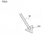
- FIG. 4 is an enlarged view of a different shape of bulging portion 32A of each flow adjustment plate 29.
- the bulging portion 32A has a triangular cross sectional shape widening toward the exit portion 28b of the passage-enlarged portion 28, as shown in FIG. 4 .
- the bulging portion may have such a shape instead of the circular cross sectional shape shown in FIG. 3B .
- the triangular cross sectional shape of the bulging portion 32A prevents air having collided with the end portion of each flow adjustment plate 29 from greatly deviating from the flow adjustment plate 29, and makes it easier for air to flow along the flow adjustment plate 29.
- the bulging portions 32 of the flow adjustment plates 29 are linearly arranged in the width direction of the passage-enlarged portion 28, air having entered the passage-enlarged portion 28 collides with a row of the bulging portions 32 arranged at narrow intervals. For this reason, a disturbance of airflow is more likely to occur.
- the bulging portions 32 of the flow adjustment plates 29 are arranged along a virtual circular arc 35 protruding toward the exit portion 28b of the passage-enlarged portion 28 (toward the cooling cylinders 21), as shown in FIG. 3 .
- a space 36 partially surrounded by the bulging portions 32 arranged in a circular arc is created at the entrance portion 28a of the passage-enlarged portion 28.
- air having entered the passage-enlarged portion 28 first flowing through the above space 36, and then, smoothly enters the gaps between the flow adjustment plates 29 while spreading radially. Because of this, the disturbance of airflow is less likely to occur.
- an intersection point P1 of extension lines L of the two side walls 30 of the passage-enlarged portion 28 matches a center point P2 of the circular arc 35 along which the bulging portions 32 are arranged.
- radially fanning out streamlines of air flowing while spreading in the passage-enlarged portion 28 are orthogonal to the circular arc 35 along which the bulging portions 32 are arranged. This makes it easier for air to enter the gaps between the bulging portions 32.
- the curvature of the circular arc 35 may vary depending on the shape of the passage-enlarged portion 28. For example, the curvature radius R of the circular arc 35 is 135 mm plus or minus 5.
- Exit-side end portions of the flow adjustment plates 29 are level with the end of the exit portion 28b of the passage-enlarged portion 28, and arranged on a straight line. This ensures that the flow of air having entered the passage-enlarged portion 28 is adjusted by the flow adjustment plates 29 before reaching the exit portion 28b of the passage-enlarged portion 28.
- FIG. 6A to FIG. 7C respectively show the analysis results (speed distributions) for Examples 1 to 4 and Comparative Examples 1 and 2.
- the column "dispersion in speeds" in FIG. 5 has values showing the degree of dispersion in the speeds with respect to the width direction at the exit portion 28b of the passage-enlarged portion 28, expressed as standard deviation.
- the values representing the degree of dispersion in the speeds (standard deviation) in FIG. 5 the value closest to 0 (zero) has the lowest degree of the dispersion.
- each flow adjustment plate 29 has no bulging portion 32.
- the bulging portions 32 are provided but arranged linearly.
- each bulging portion 32 is formed by a cylindrical rod having a diameter of 8 mm.
- each bulging portion 32 is formed by a triangular rod with a side length of 8 mm.
Landscapes
- Engineering & Computer Science (AREA)
- Mechanical Engineering (AREA)
- Textile Engineering (AREA)
- Spinning Methods And Devices For Manufacturing Artificial Fibers (AREA)
Abstract
Description
- The present invention relates to a yarn cooler configured to cool yarns spun out from a spinning device.
- In the field of melt spinning, there has been known a yarn cooler configured to cool yarns spun out from a spinning device. For example, as disclosed in Patent Literature 1 (Japanese Unexamined Patent Publication No.
2011-252260 - The duct of such a yarn cooler has a portion in which the width of a passage in the duct increases toward the yarn cooling unit. Herein, such a portion is referred to as a passage-enlarged portion. In the passage-enlarged portion, air tends to flow in the following manner: the flow rate of air is the highest at a central part of this portion in the width direction of the passage; and the farther the airflow is from the central part, the lower the flow rate is. This flow-rate distribution may cause unevenness in cooling of the yarn in the yarn cooling unit. To deal with this, it is desirable to equalize the flow rates as uniform as possible with respect to the width direction by adjusting airflows in the passage-enlarged portion.
- In relation to this, Patent Literature 2 (Japanese Unexamined Patent Publication No.
H08-201215 Patent Literature 2, upstream end portions of the partition plates, which ends are located upstream in a flow path, are aligned in a straight line in the width direction of the passage. That is, the upstream end portions of the partition plates are at the same level. - Patent Literature 3 (Japanese Patent No.
4829002 Patent Literature 3, an upstream end portion of each wind direction changing member has a bulging shape. As well as inPatent Literature 2, the end portions of the wind direction changing members are at the same level and aligned in a straight line in the width direction, also inPatent Literature 3. -
Patent Literatures - An object of the present invention is to suppress a disturbance of flow in a passage-enlarged portion and to minimize the degree of dispersion in flow rates with respect to the width direction of a passage in the passage-enlarged portion.
- According to a first aspect of the invention, a yarn cooler includes: at least one yarn cooling unit configured to cool a yarn spun out from a spinning device by gas blown to the yarn; and a gas supply unit having a passage through which gas is supplied to the yarn cooling unit,
the gas supply unit including: a sector-like passage-enlarged portion in which the width of the passage increases toward the yarn cooling unit; and a plurality of flow adjustment plates arranged in the passage-enlarged portion so as to radially fan out toward an exit portion of the passage-enlarged portion, each of the flow adjustment plates including a bulging portion at its end portion closer to an entrance portion of the passage-enlarged portion, the bulging portions being arranged in an arc protruding toward the exit portion of the passage-enlarged portion. - In this aspect, gas flowing through the gas supply unit enters the yarn cooling unit after spreading in the midway passage-enlarged portion. In the passage-enlarged portion, the radially arranged flow adjustment plates adjust the flow of gas. When gas enters the passage-enlarged portion, gas collides with the entrance-side end portion of each flow adjustment plate (the end portions closer to the entrance portion of the passage-enlarged portion). Thus, the flow of gas tends to greatly deviate from the flow adjustment plates to cause a disturbance of the flow. In this regard, in the present invention, each flow adjustment plate has the bulging portion at the entrance-side end portion of the plate. By virtue of this arrangement, gas flows into the gaps between the flow adjustment plates along the surfaces of the bulging portions, and this reduces the possibility that the flow of gas greatly deviates from the flow adjustment plates.
- If the bulging portions of the flow adjustment plates are arranged linearly in the width direction of the passage-enlarged portion, the disturbance is more likely to occur because gas having entered the passage-enlarged portion collides with a row of the bulging portions aligned at smaller intervals. In this regard, the bulging portions are arranged in an arc protruding toward the exit portion of the passage-enlarged portion in the present invention. That is, the entrance portion of the passage-enlarged portion has a space partially surrounded by the bulging portions. Thus, gas having entered the passage-enlarged portion first flowing through the above space, and then, smoothly enters the gaps between the flow adjustment plates while spreading radially. Because of this, the disturbance of the flow of gas is less likely to occur.
- According to a second aspect of the invention, the yarn cooler of the first aspect is arranged such that each bulging portion has a curved surface.
- In this aspect, the surface of each bulging portion is curved. This makes it easier for gas to flow along the surfaces of the bulging portions, and reduces the possibility that the flow deviates from the flow adjustment plates.
- According to a third aspect of the invention, the yarn cooler of the second aspect is arranged such that each bulging portion has a circular cross sectional shape.
- In this aspect, the cross sectional shape of each bulging portion is circular. Such bulging portions are processed easily, and advantageous in terms of cost.
- According to a fourth aspect of the invention, the yarn cooler of the third aspect is arranged such that a diameter of each bulging portion is not less than 5 mm and not more than 16 mm.
- If each bulging portion is too small, the effect of reducing the possibility of deviation from the flow adjustment plates is smaller. To the contrary, if each bulging portion is too large, there is a large passage resistance, which makes it difficult for gas to enter the gaps between the flow adjustment plates. For this reason, it is preferable that the diameter of each bulging portion is not less than 5 mm and not more than 16 mm.
- According to a fifth aspect of the invention, the yarn cooler of the first aspect is arranged such that each bulging portion has a triangular cross sectional shape which widens toward the exit portion of the passage-enlarged portion.
- The triangular cross sectional shape of each bulging portion which widens toward the exit portion prevents the flow of gas having contacted the end portion of each flow adjustment plate from greatly deviating from the flow adjustment plate and makes it easier for gas to flow along the flow adjustment plate.
- According to a sixth aspect of the invention, the yarn cooler of any one of the first to fifth aspects is arranged such that an intersection of extension lines of two side walls of the sector-like passage-enlarged portion matches a center point of the arc along which the bulging portions are arranged.
- In this aspect, the intersection of the extension lines of the two side walls of the sector-like passage-enlarged portion matches the center point of the arc along which the bulging portions are arranged. Because of this, radially fanning out streamlines of gas flowing while spreading in the passage-enlarged portion are orthogonal to the arc along which the bulging portions are arranged. This makes it easier for gas to enter the gaps between the bulging portions.
- According to a seventh aspect of the invention, the yarn cooler of any one of the first to sixth aspects is arranged such that an angle between each two adjacent plates of the flow adjustment plates is not less than 6 degrees and not more than 16 degrees.
- If the gap between each two adjacent flow adjustment plates is too narrow, it is difficult for gas to flow. Meanwhile, if the gap is too wide, their flow adjustment effect is low. For this reason, it is preferable that the angle between each two adjacent flow adjustment plates is not less than 6 degrees and not more than 16 degrees.
- According to an eighth aspect of the invention, the yarn cooler of any one of the first to seventh aspects is arranged such that the at least one yarn cooling unit includes a plurality of yarn cooling units, the yarn cooler further includes a box accommodating the yarn cooling units, the yarn cooling units are arranged in a predetermined direction in the box, and the exit portion of the passage-enlarged portion is coupled to a side portion of the box that is located on a side of the box in a direction orthogonal to the predetermined direction.
- The exit portion of the passage-enlarged portion is coupled to a side portion of the box accommodating the yarn cooling units, which side portion is on a side of the box in the direction orthogonal to the arrangement direction of the yarn cooling units. If the degree of dispersion in the flow rates with respect to the width direction is high at the exit portion of the passage-enlarged portion, there is caused a difference in the cooling capability among the yarn cooling units. Adoption of the arrangement of the flow adjustment plates in the present invention minimizes the unevenness in the flow rates at the exit portion of the passage-enlarged portion, and this makes the difference in the cooling capability among the yarn cooling units smaller.
-
-
FIG. 1 is a cross section of a melt spinning device of an embodiment of the present invention. -
FIG. 2 is a cross section taken along a line II-II inFIG. 1 . -
FIG. 3A is a cross section of a passage-enlarged portion taken along a line III-III inFIG. 1 .FIG. 3B is an enlarged view of a bulging portion of each flow adjustment plate inFIG. 3A . -
FIG. 4 is an enlarged view of a different shape of bulging portion of the flow adjustment plate. -
FIG. 5 is a table showing conditions regarding end portions (bulging portions) of the flow adjustment plates and data for the degree of dispersion in speeds obtained through analysis, with respect to Examples and Comparative Examples. -
FIG. 6A to FIG. 6C respectively show analysis results (speed distributions in the passage-enlarged portion) in Examples 1 to 3. -
FIG. 7A to FIG. 7C respectively show analysis results (speed distributions in the passage-enlarged portion) in Examples 4 and Comparative Examples 1 and 2. -
FIG. 8A and FIG. 8B each is an enlarged view of a bulging portion of each flow adjustment plate in a modification. -
FIG. 9 is a cross section of a passage-enlarged portion of another modification. - The following will describe an embodiment of the present invention.
FIG. 1 is a cross section of a melt spinning device of the present embodiment.FIG. 2 is a cross section taken along a line II-II inFIG. 1 . The description below is given on the premise that the up-down direction, front-back direction, and left-right direction inFIG. 1 andFIG. 2 are respectively the up-down direction, front-back direction, and left-right direction relative to amelt spinning device 1 in the present embodiment. - The
melt spinning device 1 of the present embodiment includes members such as aspinning device 2, ayarn cooler 3, and oil guides 4. Thespinning device 2 includes aspinning beam 10 andpack housings 11 provided in thespinning beam 10. To thepack housings 11, spinning packs 12 are attached, respectively. The pack housings 11 (spinning packs 12) are staggered to form two lines along the left-right direction (i.e., the direction orthogonal to the sheet ofFIG. 1 ). To the spinningpack 12 attached to eachpack housing 11, molten polymer is supplied from an unillustrated pipe or the like in thespinning beam 10. - Each spinning
pack 12 has, at its lower end portion, aspinneret 13 having nozzles. The supplied molten polymer is spun out from the spinningpack 12 through the nozzles of thespinneret 13. The polymer spun out through the nozzles is cooled at theyarn cooler 3 into filaments f. Theyarn cooler 3 will be described later. To put it differently, one multi-filament yarn Y formed of plural filaments f is spun out from onespinneret 13. - The
yarn cooler 3 is provided below thespinning device 2. Theyarn cooler 3 is configured to cool and solidify molten polymer spun out from the spinning packs 12. As shownFIG. 1 andFIG. 2 , theyarn cooler 3 includes: abox 20; cooling cylinders 21 (yarn cooling unit(s) of the present invention) accommodated in thebox 20; andpartitioning cylinders 22. - The internal space of the
box 20 is partitioned into upper and lower spaces by a horizontalflow adjustment plate 23 made of a material having flow adjustment capability such as punching metal. In the upper space of thebox 20, the coolingcylinders 21 are provided directly below the spinning packs 12, respectively. That is, the coolingcylinders 21 are staggered along the left-right direction in accordance with the arrangement of the spinning packs 12, as shown inFIG. 2 . The wall of each coolingcylinder 21 is, in a manner similar to theflow adjustment plate 23, made of a material having flow adjustment capability such as punching metal. In the meanwhile, in the lower space of thebox 20, thepartitioning cylinders 22 are provided directly below the coolingcylinders 21, respectively. Being different from the coolingcylinders 21, the wall of eachpartitioning cylinder 22 is made of an air-impermeable material. - A yarn Y spun out from a spinning
pack 12 and made of filaments f passes through the internal spaces of thecooling cylinder 21 and thepartitioning cylinder 22 which are directly below the spinningpack 12. In the meanwhile, as shown inFIG. 1 , aduct 25 is coupled, at its one end, to a lower portion of a rear side wall of thebox 20. The other end of theduct 25 is coupled to a compressed air source via an unillustrated main duct to which multiple ducts are connected. The compressed air source includes a compressor, a humidity controller, a compressed air tank, and the like, though not illustrated. The compressed air source feeds air as gas for cooling. Air from the compressed air source is supplied to the lower space of thebox 20 through theduct 25. The details of the structure of theduct 25 will be described later. - The flow of cooling air having entered the lower space of the
box 20 is adjusted upward while passing through the horizontalflow adjustment plate 23, and flows into the upper space of thebox 20. Because the wall of eachpartitioning cylinder 22 is air-impermeable, the cooling air does not directly flows from the lower space of thebox 20 into thepartitioning cylinder 22. The flow of air having entered the upper space of thebox 20 is adjusted when passing through the wall of each coolingcylinder 21, and flows into each coolingcylinder 21. The air is blown to each yarn Y made of the filaments f from the entire outer circumference of thecorresponding cooling cylinder 21, so that each yarn Y is cooled in thecorresponding cooling cylinder 21. - Each
oil guide 4 is provided below the corresponding coolingcylinder 21 andpartitioning cylinder 22. The yarn Y having been cooled in thecooling cylinder 21 comes into contact with theoil guide 4. During this contact, theoil guide 4 discharges oil to the yarn Y so that the oil is applied to the yarn Y. The yarn Y to which the oil has been applied by theoil guide 4 is taken up by a take-up roller (not illustrated) provided below theoil guide 4. The yarn Y is then sent to a winding device (not illustrated) and is wound onto a bobbin (not illustrated) at the winding device. - Now, a detailed description will be given for the
duct 25, which is equivalent to a gas supply unit in the present invention. Theduct 25 includes: avertical passage portion 26 extending in the up-down direction; and ahorizontal passage portion 27 extending in the front-back direction. The lower end of thevertical passage portion 26 is coupled to the aforementioned compressed air source via the main duct which is not illustrated. Thehorizontal passage portion 27 extends horizontally from the upper end of thevertical passage portion 26, and is coupled to the lower portion of the rear side wall of thebox 20. Air fed from the compressed air source flows to thebox 20, through thevertical passage portion 26 and thehorizontal passage portion 27 of theduct 25. -
FIG. 3A is a cross section taken along a line III-III inFIG. 1 .FIG. 3B is an enlarged view of a bulging portion of eachflow adjustment plate 29 shown inFIG. 3A . As shown inFIG. 1 andFIG. 3A , an upper end portion of thevertical passage portion 26 of theduct 25 forms a passage-enlargedportion 28. The passage-enlargedportion 28 has a sectorial shape such that the width of a passage therein (i.e., the width in the left-right direction) increases upward (i.e., toward the cooling cylinders 21). Herein, the width of the passage in theduct 25 is referred to as a "passage width". Twoside walls 30 of the passage-enlargedportion 28 extend to be inclined with respect to the up-down direction so that the distances from a central axis C to theside walls 30 increase in a left-right symmetrical manner. Thehorizontal passage portion 27 is coupled to an upper end portion (exit portion 28b) of the passage-enlargedportion 28. The passage width of theduct 25 increases at the passage-enlargedportion 28, which is a midway portion of theduct 25. Thehorizontal passage portion 27 connected to the passage-enlargedportion 28 extends to thebox 20 while keeping the increased passage width. - Air having entered the passage-enlarged
portion 28 through anentrance portion 28a with a smaller passage width flows toward theexit portion 28b with a larger passage width while spreading in the width direction. Note that, in the passage-enlargedportion 28, air flows in the following manner of flow-rate distribution: the flow rate of airflow is the highest at a central part in the width direction of the passage-enlargedportion 28; and the farther the airflow is from the central part, the lower its flow rate is. If air flowing in the above manner is supplied to the coolingcylinders 21, unevenness in cooling of the yarns may be caused. - Particularly, in the present embodiment, the cooling
cylinders 21 arranged in the left-right direction are accommodated in thebox 20, and theduct 25 is coupled to the rear wall of thebox 20, which is a side portion of thebox 20 located on a side of thebox 20 in a direction orthogonal to the arrangement direction of the coolingcylinders 21. Due to the above structure, if air flowing in theduct 25 with unevenness in its flow rate in the width direction (left-right direction) enters thebox 20, there is caused a variation in the speeds at which air enters into the coolingcylinders 21 in thebox 20. This causes a difference in the yarn-cooling capability. To minimize such a variation in the speeds at theexit portion 28b of the passage-enlargedportion 28, thereby to minimize the difference in the cooling capability among the coolingcylinders 21, the present embodiment employs the following arrangement. - First, flow
adjustment plates 29 are provided in the passage-enlargedportion 28. Theflow adjustment plates 29 adjust the flow of air so that air having entered through theentrance portion 28a spreads uniformly with respect to the width direction. Theflow adjustment plates 29 are arranged so as to radially fan out from theentrance portion 28a with the smaller passage width toward theexit portion 28b with the larger passage width. Theflow adjustment plates 29 are arranged at equal intervals of an angle θ (theta). If the gap between each two adjacentflow adjustment plates 29 is too narrow, it is difficult for air to flow. Meanwhile, if the gap is too wide, their flow adjustment effect is low. In view of the above, the angle θ (theta) between each two adjacentflow adjustment plates 29 is preferably not less than 6 degrees and not more than 16 degrees, and more preferably 8 degrees. - Further, each
flow adjustment plate 29 has a bulgingportion 32 at an entrance-side end portion of theplate 29, which end portion is closer to theentrance portion 28a (i.e., an end portion upstream in the flow path). The thickness of the bulgingportion 32 is larger than the thickness of a portion of theflow adjustment plate 29 that is located above the bulging portion 32 (portion on a side closer to the coolingcylinders 21 than the bulging portion 32). The bulgingportion 32 has a curved surface. To be more specific, acylindrical rod 31 extending in the direction orthogonal to the sheet ofFIG. 3 is attached to an entrance-side end portion of a plate member of eachflow adjustment plate 29. With this, the bulgingportion 32 having a circular cross section is provided. - Suppose that each
flow adjustment plate 29 does not have the bulgingportion 32. In this case, when air enters the passage-enlargedportion 28, the air collides with the entrance-side end portions of theflow adjustment plates 29. Thus, the flow of air is more likely to greatly deviate from theflow adjustment plates 29 to cause a disturbance of the flow. In this regard, in the present embodiment, eachflow adjustment plate 29 has the bulgingportion 32 at the entrance-side end portion of the plate. This arrangement enables air having entered the passage-enlargedportion 28 to flow along the surfaces of the bulgingportions 32 into the gaps between theflow adjustment plates 29. Thus, it is less likely that the flow of air greatly deviates from theflow adjustment plates 29, to reduce the possibility of the disturbance of the flow. - The curved surface of each bulging
portion 32 makes it easier for air to flow along the surface of the bulgingportion 32, and reduces the possibility that the flow of air deviates from theflow adjustment plates 29. Further, the bulgingportions 32 each having the circular cross sectional shape are processed easily, and advantageous in terms of cost. Specifically, each bulgingportion 32 is produced merely by attaching thecylindrical rod 31 to the plate member constituting theflow adjustment plate 29. - If each bulging
portion 32 is too small, the effect of reducing the possibility of the deviation from theflow adjustment plates 29 is small. To the contrary, if each bulgingportion 32 is too large, there is a large passage resistance, which makes it difficult for air to enter the gaps between theflow adjustment plates 29. In view of the above, the diameter of eachcylindrical rod 31 constituting the bulgingportion 32 is preferably not less than 5 mm and not more than 16 mm, and more preferably 8 mm. The thickness of eachflow adjustment plate 29 is on the order of 0.5 mm, for example. -
FIG. 4 is an enlarged view of a different shape of bulgingportion 32A of eachflow adjustment plate 29. The bulgingportion 32A has a triangular cross sectional shape widening toward theexit portion 28b of the passage-enlargedportion 28, as shown inFIG. 4 . The bulging portion may have such a shape instead of the circular cross sectional shape shown inFIG. 3B . The triangular cross sectional shape of the bulgingportion 32A prevents air having collided with the end portion of eachflow adjustment plate 29 from greatly deviating from theflow adjustment plate 29, and makes it easier for air to flow along theflow adjustment plate 29. - If the bulging
portions 32 of theflow adjustment plates 29 are linearly arranged in the width direction of the passage-enlargedportion 28, air having entered the passage-enlargedportion 28 collides with a row of the bulgingportions 32 arranged at narrow intervals. For this reason, a disturbance of airflow is more likely to occur. To deal with this, in the present embodiment, the bulgingportions 32 of theflow adjustment plates 29 are arranged along a virtualcircular arc 35 protruding toward theexit portion 28b of the passage-enlarged portion 28 (toward the cooling cylinders 21), as shown inFIG. 3 . In this arrangement, a space 36 partially surrounded by the bulgingportions 32 arranged in a circular arc is created at theentrance portion 28a of the passage-enlargedportion 28. Thus, air having entered the passage-enlargedportion 28 first flowing through the above space 36, and then, smoothly enters the gaps between theflow adjustment plates 29 while spreading radially. Because of this, the disturbance of airflow is less likely to occur. - As shown in
FIG. 3 , in the present embodiment, an intersection point P1 of extension lines L of the twoside walls 30 of the passage-enlargedportion 28 matches a center point P2 of thecircular arc 35 along which the bulgingportions 32 are arranged. In this arrangement, radially fanning out streamlines of air flowing while spreading in the passage-enlargedportion 28 are orthogonal to thecircular arc 35 along which the bulgingportions 32 are arranged. This makes it easier for air to enter the gaps between the bulgingportions 32. The curvature of thecircular arc 35 may vary depending on the shape of the passage-enlargedportion 28. For example, the curvature radius R of thecircular arc 35 is 135 mm plus or minus 5. - Exit-side end portions of the
flow adjustment plates 29 are level with the end of theexit portion 28b of the passage-enlargedportion 28, and arranged on a straight line. This ensures that the flow of air having entered the passage-enlargedportion 28 is adjusted by theflow adjustment plates 29 before reaching theexit portion 28b of the passage-enlargedportion 28. - Examples of the present invention were compared with Comparative Examples, to verify advantageous effects of the present invention. The below-described verification of the advantageous effects is conducted by numerically analyzing the flow of air in the passage-enlarged
portion 28 for each case. -
- (1) Conditions common among all the models are as follows: (a) the number of air flow adjustment plates, 11; (b) angle between adjacent flow adjustment plates, 8 degrees; and (c) flow rate at the entrance portion, 10.8 m3/min.
- (2) Conditions regarding the bulging portions are as follows.
FIG. 5 shows the conditions for the end portion (bulging portion 32) of eachflow adjustment plate 29 in Examples and Comparative Examples. Note that "circular arc arrangement" in the column "arrangement manner of end portions" inFIG. 5 represents the arrangement manner in which the end portions of theflow adjustment plates 29 are arranged in a circular arc, as shown inFIG. 3 . Meanwhile, "linear arrangement" represents the arrangement manner in which the end portions of theflow adjustment plates 29 are arranged linearly along the width direction. -
FIG. 6A to FIG. 7C respectively show the analysis results (speed distributions) for Examples 1 to 4 and Comparative Examples 1 and 2. Further, the column "dispersion in speeds" inFIG. 5 has values showing the degree of dispersion in the speeds with respect to the width direction at theexit portion 28b of the passage-enlargedportion 28, expressed as standard deviation. As for the values representing the degree of dispersion in the speeds (standard deviation) inFIG. 5 , the value closest to 0 (zero) has the lowest degree of the dispersion. - First, as shown in
FIG. 6A to FIG. 7C , air smoothly flows from theentrance portion 28a to theexit portion 28b in Examples 1 to 4. In addition, the values of the standard deviation showing the degree of dispersion in the speeds are low in Examples. Meanwhile, in Comparative Examples 1 and 2, the flows in the passage-enlargedportion 28 are disturbed and swirls are generated. In Comparative Example 1, eachflow adjustment plate 29 has no bulgingportion 32. In Comparative Example 2, the bulgingportions 32 are provided but arranged linearly. The above results show that the following two features are very important to suppress the disturbance of flow in the passage-enlarged portion 28: (1) eachflow adjustment plate 29 has the bulgingportion 32 at the end portion of the plate; and (2) the bulgingportions 32 are arranged in an arc. - Now, reference is made to Examples 1 to 4. The disturbance of airflow is smaller and the degree of dispersion in the speeds is quite low particularly in Examples 1 and 4. In Example 1, each bulging
portion 32 is formed by a cylindrical rod having a diameter of 8 mm. In Example 4, each bulgingportion 32 is formed by a triangular rod with a side length of 8 mm. - Now, various modifications of the present embodiment will be described. The members similar to those in the embodiment above will be denoted by the same reference numerals and the explanations thereof are not repeated.
- 1] The above-described embodiment shows the case where the bulging portion of each
flow adjustment plate 29 has a circular cross sectional shape and the case where the bulging portion has a triangular cross sectional shape. However, the bulging portion may have another shape. Examples of the bulging portion having a curved surface include: a bulgingportion 32B having an elliptical cross sectional shape as shown inFIG. 8A ; and a bulgingportion 32C having a streamline shape as shown inFIG. 8B . - 2] The manner of arrangement of the bulging portions is also changeable as follows. For example, as shown in
FIG. 9 , the center point P2 of thecircular arc 35 along which the bulgingportions 32 are arranged may be shifted relative to the intersection point P1 of the extension lines L of the twoside walls 30. The center point P2 may be shifted relative to the point P1 in the direction toward the exit side as shown inFIG. 9 , or may be shifted in the opposite direction, i.e., toward the entrance side. Further, the arc along which the bulgingportions 32 are arranged does not have to be a circular arc, and may be an elliptical arc, for example. - 3] The yarn cooler of the above-described embodiment includes the cooling
cylinders 21, as the yarn cooling unit(s), each configured so that air is blown to the yarn from the entire outer circumference. However, the configuration of the yarn cooling unit is not limited to this. For example, the yarn cooling unit(s) may be configured to cool the yarn by air blown to the yarn only in a single direction, i.e., may have a so-called crossflow design.
Claims (8)
- A yarn cooler comprising:at least one yarn cooling unit configured to cool a yarn spun out from a spinning device by gas blown to the yarn; anda gas supply unit having a passage through which gas is supplied to the yarn cooling unit, the gas supply unit including:a sector-like passage-enlarged portion in which the width of the passage increases toward the yarn cooling unit; anda plurality of flow adjustment plates arranged in the passage-enlarged portion so as to radially fan out toward an exit portion of the passage-enlarged portion,each of the flow adjustment plates including a bulging portion at its end portion closer to an entrance portion of the passage-enlarged portion,the bulging portions being arranged in an arc protruding toward the exit portion of the passage-enlarged portion.
- The yarn cooler according to claim 1, wherein each bulging portion has a curved surface.
- The yarn cooler according to claim 2, wherein each bulging portion has a circular cross sectional shape.
- The yarn cooler according to claim 3, wherein a diameter of each bulging portion is not less than 5 mm and not more than 16 mm.
- The yarn cooler according to claim 1, wherein each bulging portion has a triangular cross sectional shape which widens toward the exit portion of the passage-enlarged portion.
- The yarn cooler according to any one of claims 1 to 5, wherein an intersection of extension lines of two side walls of the sector-like passage-enlarged portion matches a center point of the arc along which the bulging portions are arranged.
- The yarn cooler according to any one of claims 1 to 6, wherein an angle between each two adjacent plates of the flow adjustment plates is not less than 6 degrees and not more than 16 degrees.
- The yarn cooler according to any one of claims 1 to 7, wherein
the at least one yarn cooling unit comprises a plurality of yarn cooling units,
the yarn cooler further comprises a box accommodating the yarn cooling units,
the yarn cooling units are arranged in a predetermined direction in the box, and
the exit portion of the passage-enlarged portion is coupled to a side portion of the box that is located on a side of the box in a direction orthogonal to the predetermined direction.
Applications Claiming Priority (1)
| Application Number | Priority Date | Filing Date | Title |
|---|---|---|---|
| JP2016027676A JP6556641B2 (en) | 2016-02-17 | 2016-02-17 | Thread cooling device |
Publications (2)
| Publication Number | Publication Date |
|---|---|
| EP3208367A1 true EP3208367A1 (en) | 2017-08-23 |
| EP3208367B1 EP3208367B1 (en) | 2018-03-14 |
Family
ID=57984807
Family Applications (1)
| Application Number | Title | Priority Date | Filing Date |
|---|---|---|---|
| EP17154570.0A Active EP3208367B1 (en) | 2016-02-17 | 2017-02-03 | Yarn cooler |
Country Status (3)
| Country | Link |
|---|---|
| EP (1) | EP3208367B1 (en) |
| JP (1) | JP6556641B2 (en) |
| CN (1) | CN107090602B (en) |
Cited By (1)
| Publication number | Priority date | Publication date | Assignee | Title |
|---|---|---|---|---|
| CN111041660A (en) * | 2019-12-19 | 2020-04-21 | 杭州华利实业集团有限公司 | Moisture-absorbing quick-drying train bedding and manufacturing method thereof |
Families Citing this family (3)
| Publication number | Priority date | Publication date | Assignee | Title |
|---|---|---|---|---|
| CN108088279A (en) * | 2017-12-12 | 2018-05-29 | 无锡市金来生物科技有限公司 | Material cooling tower |
| JP7149100B2 (en) | 2018-05-16 | 2022-10-06 | Tmtマシナリー株式会社 | Spinning cooling device |
| CN115182059B (en) * | 2022-06-13 | 2023-11-14 | 桐昆集团浙江恒超化纤有限公司 | Polyester fiber spinning equipment special for high-elastic spring spinning and spinning process |
Citations (7)
| Publication number | Priority date | Publication date | Assignee | Title |
|---|---|---|---|---|
| DE2656000A1 (en) * | 1976-02-13 | 1977-08-18 | Plast Elastverarbeitungsmasch | Melt spun polymeric filament cooling appts. - has air chamber with damper controlled inlet press. regulator and guide vanes to control air flow profile |
| DE2923700A1 (en) * | 1979-06-12 | 1980-12-18 | Werner Singendonk | Blowing shaft turbulence-free blowing channels - for synthetic polymer spinning have controlled heating and cooling of flow |
| JPH08201215A (en) | 1995-01-23 | 1996-08-09 | Mitsubishi Heavy Ind Ltd | Rectifying duct |
| JP2003213517A (en) * | 2002-01-18 | 2003-07-30 | Toray Ind Inc | Method and apparatus for producing synthetic fiber |
| JP4829002B2 (en) | 2006-04-28 | 2011-11-30 | 川崎重工業株式会社 | Cross air blower |
| EP2392698A1 (en) * | 2010-06-04 | 2011-12-07 | TMT Machinery, Inc. | Filament cooler |
| CN105177738A (en) * | 2015-09-30 | 2015-12-23 | 苏州金泉新材料股份有限公司 | Cross air blow cooling device for melt spinning |
Family Cites Families (12)
| Publication number | Priority date | Publication date | Assignee | Title |
|---|---|---|---|---|
| JPS4734257Y1 (en) * | 1969-07-31 | 1972-10-17 | ||
| JPS51144511U (en) * | 1975-05-06 | 1976-11-20 | ||
| JPH0311065U (en) * | 1989-06-19 | 1991-02-01 | ||
| JPH10158920A (en) * | 1996-11-19 | 1998-06-16 | Toray Eng Co Ltd | Yarn cooling device |
| JP3060102U (en) * | 1998-11-09 | 1999-07-30 | 清坤 曽 | Spinning cooling mechanism |
| JP3781735B2 (en) * | 2003-04-07 | 2006-05-31 | シャープ株式会社 | Rectifier |
| CN101535537B (en) * | 2006-11-10 | 2011-01-26 | 欧瑞康纺织有限及两合公司 | Process and device for melt-spinning and cooling synthetic filaments |
| JP4772759B2 (en) * | 2007-07-26 | 2011-09-14 | 株式会社東芝 | Diffuser |
| JP2010077553A (en) * | 2008-09-25 | 2010-04-08 | Toray Ind Inc | Apparatus and method for producing filament yarn |
| JP5925657B2 (en) * | 2012-10-03 | 2016-05-25 | Tmtマシナリー株式会社 | Melt spinning equipment |
| JP6069019B2 (en) * | 2013-02-19 | 2017-01-25 | Tmtマシナリー株式会社 | Yarn cooling device |
| JP2015014071A (en) * | 2013-07-08 | 2015-01-22 | Tmtマシナリー株式会社 | Yarn cooling device |
-
2016
- 2016-02-17 JP JP2016027676A patent/JP6556641B2/en active Active
-
2017
- 2017-02-03 EP EP17154570.0A patent/EP3208367B1/en active Active
- 2017-02-07 CN CN201710067513.8A patent/CN107090602B/en active Active
Patent Citations (8)
| Publication number | Priority date | Publication date | Assignee | Title |
|---|---|---|---|---|
| DE2656000A1 (en) * | 1976-02-13 | 1977-08-18 | Plast Elastverarbeitungsmasch | Melt spun polymeric filament cooling appts. - has air chamber with damper controlled inlet press. regulator and guide vanes to control air flow profile |
| DE2923700A1 (en) * | 1979-06-12 | 1980-12-18 | Werner Singendonk | Blowing shaft turbulence-free blowing channels - for synthetic polymer spinning have controlled heating and cooling of flow |
| JPH08201215A (en) | 1995-01-23 | 1996-08-09 | Mitsubishi Heavy Ind Ltd | Rectifying duct |
| JP2003213517A (en) * | 2002-01-18 | 2003-07-30 | Toray Ind Inc | Method and apparatus for producing synthetic fiber |
| JP4829002B2 (en) | 2006-04-28 | 2011-11-30 | 川崎重工業株式会社 | Cross air blower |
| EP2392698A1 (en) * | 2010-06-04 | 2011-12-07 | TMT Machinery, Inc. | Filament cooler |
| JP2011252260A (en) | 2010-06-04 | 2011-12-15 | Tmt Machinery Inc | Yarn cooling device |
| CN105177738A (en) * | 2015-09-30 | 2015-12-23 | 苏州金泉新材料股份有限公司 | Cross air blow cooling device for melt spinning |
Cited By (1)
| Publication number | Priority date | Publication date | Assignee | Title |
|---|---|---|---|---|
| CN111041660A (en) * | 2019-12-19 | 2020-04-21 | 杭州华利实业集团有限公司 | Moisture-absorbing quick-drying train bedding and manufacturing method thereof |
Also Published As
| Publication number | Publication date |
|---|---|
| CN107090602A (en) | 2017-08-25 |
| JP6556641B2 (en) | 2019-08-07 |
| CN107090602B (en) | 2020-07-14 |
| JP2017145525A (en) | 2017-08-24 |
| EP3208367B1 (en) | 2018-03-14 |
Similar Documents
| Publication | Publication Date | Title |
|---|---|---|
| EP3208367B1 (en) | Yarn cooler | |
| CN110541241B (en) | Apparatus and method for making spunbond nonwoven fabrics from continuous filaments | |
| EP3492634B1 (en) | Melt spinning device | |
| JP5526531B2 (en) | Spinning cooling device and melt spinning method | |
| JP6069019B2 (en) | Yarn cooling device | |
| CN110541206B (en) | Apparatus and method for making spunbond nonwoven fabrics from continuous filaments | |
| JP2015014071A (en) | Yarn cooling device | |
| JPS6197413A (en) | Air cooling chamber and method for guiding cooling air thereto | |
| EP1629141B1 (en) | Apparatus and method for controlling airflow in a fiber extrusion system | |
| JP2010070887A (en) | Cooling device for spinning and melt-spinning method | |
| CN106637443B (en) | Cross air blowing device and spinning machine | |
| EP3441507B1 (en) | Yarn cooler | |
| CN113957547B (en) | Production process method of multipurpose net-woven fiber raw material | |
| US20160160395A1 (en) | Gas supply blowout nozzle and method of producing flame-proofed fiber and carbon fiber | |
| US20090317505A1 (en) | Device for drawing filaments | |
| US4198270A (en) | Head box for a paper making machine | |
| JP2006241611A (en) | Melt-spinning equipment of synthetic fiber | |
| JP2002038328A (en) | Melt spinning equipment | |
| JP4988318B2 (en) | Multi-spindle melt spinning apparatus and ultrafine multifilament yarn obtained therefrom | |
| CN103710768A (en) | Melt spinning apparatus | |
| JP5332253B2 (en) | Filament yarn manufacturing apparatus and manufacturing method | |
| JP7656522B2 (en) | Spinning production equipment | |
| EP4596767A1 (en) | Interlacing apparatus and spun yarn take-up machine | |
| WO2025033484A1 (en) | Yarn cooling device | |
| JPH07109614A (en) | Method and apparatus for melt spinning ultrafine multifilament yarn |
Legal Events
| Date | Code | Title | Description |
|---|---|---|---|
| PUAI | Public reference made under article 153(3) epc to a published international application that has entered the european phase |
Free format text: ORIGINAL CODE: 0009012 |
|
| STAA | Information on the status of an ep patent application or granted ep patent |
Free format text: STATUS: THE APPLICATION HAS BEEN PUBLISHED |
|
| AK | Designated contracting states |
Kind code of ref document: A1 Designated state(s): AL AT BE BG CH CY CZ DE DK EE ES FI FR GB GR HR HU IE IS IT LI LT LU LV MC MK MT NL NO PL PT RO RS SE SI SK SM TR |
|
| AX | Request for extension of the european patent |
Extension state: BA ME |
|
| STAA | Information on the status of an ep patent application or granted ep patent |
Free format text: STATUS: REQUEST FOR EXAMINATION WAS MADE |
|
| 17P | Request for examination filed |
Effective date: 20171017 |
|
| RBV | Designated contracting states (corrected) |
Designated state(s): AL AT BE BG CH CY CZ DE DK EE ES FI FR GB GR HR HU IE IS IT LI LT LU LV MC MK MT NL NO PL PT RO RS SE SI SK SM TR |
|
| GRAP | Despatch of communication of intention to grant a patent |
Free format text: ORIGINAL CODE: EPIDOSNIGR1 |
|
| STAA | Information on the status of an ep patent application or granted ep patent |
Free format text: STATUS: GRANT OF PATENT IS INTENDED |
|
| INTG | Intention to grant announced |
Effective date: 20171201 |
|
| GRAS | Grant fee paid |
Free format text: ORIGINAL CODE: EPIDOSNIGR3 |
|
| GRAA | (expected) grant |
Free format text: ORIGINAL CODE: 0009210 |
|
| STAA | Information on the status of an ep patent application or granted ep patent |
Free format text: STATUS: THE PATENT HAS BEEN GRANTED |
|
| AK | Designated contracting states |
Kind code of ref document: B1 Designated state(s): AL AT BE BG CH CY CZ DE DK EE ES FI FR GB GR HR HU IE IS IT LI LT LU LV MC MK MT NL NO PL PT RO RS SE SI SK SM TR |
|
| REG | Reference to a national code |
Ref country code: GB Ref legal event code: FG4D |
|
| REG | Reference to a national code |
Ref country code: CH Ref legal event code: EP Ref country code: AT Ref legal event code: REF Ref document number: 978975 Country of ref document: AT Kind code of ref document: T Effective date: 20180315 |
|
| REG | Reference to a national code |
Ref country code: IE Ref legal event code: FG4D |
|
| REG | Reference to a national code |
Ref country code: DE Ref legal event code: R096 Ref document number: 602017000014 Country of ref document: DE |
|
| REG | Reference to a national code |
Ref country code: NL Ref legal event code: MP Effective date: 20180314 |
|
| REG | Reference to a national code |
Ref country code: LT Ref legal event code: MG4D |
|
| PG25 | Lapsed in a contracting state [announced via postgrant information from national office to epo] |
Ref country code: LT Free format text: LAPSE BECAUSE OF FAILURE TO SUBMIT A TRANSLATION OF THE DESCRIPTION OR TO PAY THE FEE WITHIN THE PRESCRIBED TIME-LIMIT Effective date: 20180314 Ref country code: HR Free format text: LAPSE BECAUSE OF FAILURE TO SUBMIT A TRANSLATION OF THE DESCRIPTION OR TO PAY THE FEE WITHIN THE PRESCRIBED TIME-LIMIT Effective date: 20180314 Ref country code: CY Free format text: LAPSE BECAUSE OF FAILURE TO SUBMIT A TRANSLATION OF THE DESCRIPTION OR TO PAY THE FEE WITHIN THE PRESCRIBED TIME-LIMIT Effective date: 20180314 Ref country code: NO Free format text: LAPSE BECAUSE OF FAILURE TO SUBMIT A TRANSLATION OF THE DESCRIPTION OR TO PAY THE FEE WITHIN THE PRESCRIBED TIME-LIMIT Effective date: 20180614 Ref country code: FI Free format text: LAPSE BECAUSE OF FAILURE TO SUBMIT A TRANSLATION OF THE DESCRIPTION OR TO PAY THE FEE WITHIN THE PRESCRIBED TIME-LIMIT Effective date: 20180314 |
|
| REG | Reference to a national code |
Ref country code: AT Ref legal event code: MK05 Ref document number: 978975 Country of ref document: AT Kind code of ref document: T Effective date: 20180314 |
|
| PG25 | Lapsed in a contracting state [announced via postgrant information from national office to epo] |
Ref country code: RS Free format text: LAPSE BECAUSE OF FAILURE TO SUBMIT A TRANSLATION OF THE DESCRIPTION OR TO PAY THE FEE WITHIN THE PRESCRIBED TIME-LIMIT Effective date: 20180314 Ref country code: BG Free format text: LAPSE BECAUSE OF FAILURE TO SUBMIT A TRANSLATION OF THE DESCRIPTION OR TO PAY THE FEE WITHIN THE PRESCRIBED TIME-LIMIT Effective date: 20180614 Ref country code: GR Free format text: LAPSE BECAUSE OF FAILURE TO SUBMIT A TRANSLATION OF THE DESCRIPTION OR TO PAY THE FEE WITHIN THE PRESCRIBED TIME-LIMIT Effective date: 20180615 Ref country code: LV Free format text: LAPSE BECAUSE OF FAILURE TO SUBMIT A TRANSLATION OF THE DESCRIPTION OR TO PAY THE FEE WITHIN THE PRESCRIBED TIME-LIMIT Effective date: 20180314 Ref country code: SE Free format text: LAPSE BECAUSE OF FAILURE TO SUBMIT A TRANSLATION OF THE DESCRIPTION OR TO PAY THE FEE WITHIN THE PRESCRIBED TIME-LIMIT Effective date: 20180314 |
|
| PG25 | Lapsed in a contracting state [announced via postgrant information from national office to epo] |
Ref country code: AL Free format text: LAPSE BECAUSE OF FAILURE TO SUBMIT A TRANSLATION OF THE DESCRIPTION OR TO PAY THE FEE WITHIN THE PRESCRIBED TIME-LIMIT Effective date: 20180314 Ref country code: RO Free format text: LAPSE BECAUSE OF FAILURE TO SUBMIT A TRANSLATION OF THE DESCRIPTION OR TO PAY THE FEE WITHIN THE PRESCRIBED TIME-LIMIT Effective date: 20180314 Ref country code: NL Free format text: LAPSE BECAUSE OF FAILURE TO SUBMIT A TRANSLATION OF THE DESCRIPTION OR TO PAY THE FEE WITHIN THE PRESCRIBED TIME-LIMIT Effective date: 20180314 Ref country code: EE Free format text: LAPSE BECAUSE OF FAILURE TO SUBMIT A TRANSLATION OF THE DESCRIPTION OR TO PAY THE FEE WITHIN THE PRESCRIBED TIME-LIMIT Effective date: 20180314 Ref country code: PL Free format text: LAPSE BECAUSE OF FAILURE TO SUBMIT A TRANSLATION OF THE DESCRIPTION OR TO PAY THE FEE WITHIN THE PRESCRIBED TIME-LIMIT Effective date: 20180314 |
|
| PG25 | Lapsed in a contracting state [announced via postgrant information from national office to epo] |
Ref country code: SK Free format text: LAPSE BECAUSE OF FAILURE TO SUBMIT A TRANSLATION OF THE DESCRIPTION OR TO PAY THE FEE WITHIN THE PRESCRIBED TIME-LIMIT Effective date: 20180314 Ref country code: CZ Free format text: LAPSE BECAUSE OF FAILURE TO SUBMIT A TRANSLATION OF THE DESCRIPTION OR TO PAY THE FEE WITHIN THE PRESCRIBED TIME-LIMIT Effective date: 20180314 Ref country code: AT Free format text: LAPSE BECAUSE OF FAILURE TO SUBMIT A TRANSLATION OF THE DESCRIPTION OR TO PAY THE FEE WITHIN THE PRESCRIBED TIME-LIMIT Effective date: 20180314 Ref country code: SM Free format text: LAPSE BECAUSE OF FAILURE TO SUBMIT A TRANSLATION OF THE DESCRIPTION OR TO PAY THE FEE WITHIN THE PRESCRIBED TIME-LIMIT Effective date: 20180314 |
|
| REG | Reference to a national code |
Ref country code: DE Ref legal event code: R097 Ref document number: 602017000014 Country of ref document: DE |
|
| PG25 | Lapsed in a contracting state [announced via postgrant information from national office to epo] |
Ref country code: PT Free format text: LAPSE BECAUSE OF FAILURE TO SUBMIT A TRANSLATION OF THE DESCRIPTION OR TO PAY THE FEE WITHIN THE PRESCRIBED TIME-LIMIT Effective date: 20180716 |
|
| PLBE | No opposition filed within time limit |
Free format text: ORIGINAL CODE: 0009261 |
|
| STAA | Information on the status of an ep patent application or granted ep patent |
Free format text: STATUS: NO OPPOSITION FILED WITHIN TIME LIMIT |
|
| PG25 | Lapsed in a contracting state [announced via postgrant information from national office to epo] |
Ref country code: DK Free format text: LAPSE BECAUSE OF FAILURE TO SUBMIT A TRANSLATION OF THE DESCRIPTION OR TO PAY THE FEE WITHIN THE PRESCRIBED TIME-LIMIT Effective date: 20180314 |
|
| 26N | No opposition filed |
Effective date: 20181217 |
|
| PG25 | Lapsed in a contracting state [announced via postgrant information from national office to epo] |
Ref country code: IT Free format text: LAPSE BECAUSE OF FAILURE TO SUBMIT A TRANSLATION OF THE DESCRIPTION OR TO PAY THE FEE WITHIN THE PRESCRIBED TIME-LIMIT Effective date: 20180314 |
|
| PG25 | Lapsed in a contracting state [announced via postgrant information from national office to epo] |
Ref country code: ES Free format text: LAPSE BECAUSE OF FAILURE TO SUBMIT A TRANSLATION OF THE DESCRIPTION OR TO PAY THE FEE WITHIN THE PRESCRIBED TIME-LIMIT Effective date: 20180314 |
|
| PG25 | Lapsed in a contracting state [announced via postgrant information from national office to epo] |
Ref country code: LU Free format text: LAPSE BECAUSE OF NON-PAYMENT OF DUE FEES Effective date: 20190203 Ref country code: MC Free format text: LAPSE BECAUSE OF FAILURE TO SUBMIT A TRANSLATION OF THE DESCRIPTION OR TO PAY THE FEE WITHIN THE PRESCRIBED TIME-LIMIT Effective date: 20180314 |
|
| REG | Reference to a national code |
Ref country code: BE Ref legal event code: MM Effective date: 20190228 |
|
| REG | Reference to a national code |
Ref country code: IE Ref legal event code: MM4A |
|
| PG25 | Lapsed in a contracting state [announced via postgrant information from national office to epo] |
Ref country code: IE Free format text: LAPSE BECAUSE OF NON-PAYMENT OF DUE FEES Effective date: 20190203 |
|
| PG25 | Lapsed in a contracting state [announced via postgrant information from national office to epo] |
Ref country code: FR Free format text: LAPSE BECAUSE OF NON-PAYMENT OF DUE FEES Effective date: 20190228 Ref country code: BE Free format text: LAPSE BECAUSE OF NON-PAYMENT OF DUE FEES Effective date: 20190228 |
|
| PG25 | Lapsed in a contracting state [announced via postgrant information from national office to epo] |
Ref country code: TR Free format text: LAPSE BECAUSE OF FAILURE TO SUBMIT A TRANSLATION OF THE DESCRIPTION OR TO PAY THE FEE WITHIN THE PRESCRIBED TIME-LIMIT Effective date: 20180314 |
|
| PG25 | Lapsed in a contracting state [announced via postgrant information from national office to epo] |
Ref country code: MT Free format text: LAPSE BECAUSE OF NON-PAYMENT OF DUE FEES Effective date: 20190203 |
|
| REG | Reference to a national code |
Ref country code: CH Ref legal event code: PL |
|
| PG25 | Lapsed in a contracting state [announced via postgrant information from national office to epo] |
Ref country code: LI Free format text: LAPSE BECAUSE OF NON-PAYMENT OF DUE FEES Effective date: 20200229 Ref country code: CH Free format text: LAPSE BECAUSE OF NON-PAYMENT OF DUE FEES Effective date: 20200229 |
|
| PG25 | Lapsed in a contracting state [announced via postgrant information from national office to epo] |
Ref country code: IS Free format text: LAPSE BECAUSE OF FAILURE TO SUBMIT A TRANSLATION OF THE DESCRIPTION OR TO PAY THE FEE WITHIN THE PRESCRIBED TIME-LIMIT Effective date: 20180714 |
|
| PG25 | Lapsed in a contracting state [announced via postgrant information from national office to epo] |
Ref country code: HU Free format text: LAPSE BECAUSE OF FAILURE TO SUBMIT A TRANSLATION OF THE DESCRIPTION OR TO PAY THE FEE WITHIN THE PRESCRIBED TIME-LIMIT; INVALID AB INITIO Effective date: 20170203 |
|
| GBPC | Gb: european patent ceased through non-payment of renewal fee |
Effective date: 20210203 |
|
| PG25 | Lapsed in a contracting state [announced via postgrant information from national office to epo] |
Ref country code: SI Free format text: LAPSE BECAUSE OF FAILURE TO SUBMIT A TRANSLATION OF THE DESCRIPTION OR TO PAY THE FEE WITHIN THE PRESCRIBED TIME-LIMIT Effective date: 20180314 |
|
| PG25 | Lapsed in a contracting state [announced via postgrant information from national office to epo] |
Ref country code: GB Free format text: LAPSE BECAUSE OF NON-PAYMENT OF DUE FEES Effective date: 20210203 |
|
| PG25 | Lapsed in a contracting state [announced via postgrant information from national office to epo] |
Ref country code: MK Free format text: LAPSE BECAUSE OF FAILURE TO SUBMIT A TRANSLATION OF THE DESCRIPTION OR TO PAY THE FEE WITHIN THE PRESCRIBED TIME-LIMIT Effective date: 20180314 |
|
| P01 | Opt-out of the competence of the unified patent court (upc) registered |
Effective date: 20230426 |
|
| PGFP | Annual fee paid to national office [announced via postgrant information from national office to epo] |
Ref country code: DE Payment date: 20260225 Year of fee payment: 10 |