EP3208242A1 - Ultrasound method and device for disinfecting water - Google Patents
Ultrasound method and device for disinfecting water Download PDFInfo
- Publication number
- EP3208242A1 EP3208242A1 EP16472001.3A EP16472001A EP3208242A1 EP 3208242 A1 EP3208242 A1 EP 3208242A1 EP 16472001 A EP16472001 A EP 16472001A EP 3208242 A1 EP3208242 A1 EP 3208242A1
- Authority
- EP
- European Patent Office
- Prior art keywords
- water
- blades
- flow
- passage
- frequency
- Prior art date
- Legal status (The legal status is an assumption and is not a legal conclusion. Google has not performed a legal analysis and makes no representation as to the accuracy of the status listed.)
- Granted
Links
Images

Classifications
-
- C—CHEMISTRY; METALLURGY
- C02—TREATMENT OF WATER, WASTE WATER, SEWAGE, OR SLUDGE
- C02F—TREATMENT OF WATER, WASTE WATER, SEWAGE, OR SLUDGE
- C02F1/00—Treatment of water, waste water, or sewage
- C02F1/34—Treatment of water, waste water, or sewage with mechanical oscillations
-
- C—CHEMISTRY; METALLURGY
- C02—TREATMENT OF WATER, WASTE WATER, SEWAGE, OR SLUDGE
- C02F—TREATMENT OF WATER, WASTE WATER, SEWAGE, OR SLUDGE
- C02F1/00—Treatment of water, waste water, or sewage
- C02F1/34—Treatment of water, waste water, or sewage with mechanical oscillations
- C02F1/36—Treatment of water, waste water, or sewage with mechanical oscillations ultrasonic vibrations
-
- C—CHEMISTRY; METALLURGY
- C02—TREATMENT OF WATER, WASTE WATER, SEWAGE, OR SLUDGE
- C02F—TREATMENT OF WATER, WASTE WATER, SEWAGE, OR SLUDGE
- C02F2301/00—General aspects of water treatment
- C02F2301/02—Fluid flow conditions
- C02F2301/026—Spiral, helicoidal, radial
-
- C—CHEMISTRY; METALLURGY
- C02—TREATMENT OF WATER, WASTE WATER, SEWAGE, OR SLUDGE
- C02F—TREATMENT OF WATER, WASTE WATER, SEWAGE, OR SLUDGE
- C02F2301/00—General aspects of water treatment
- C02F2301/02—Fluid flow conditions
- C02F2301/028—Tortuous
-
- C—CHEMISTRY; METALLURGY
- C02—TREATMENT OF WATER, WASTE WATER, SEWAGE, OR SLUDGE
- C02F—TREATMENT OF WATER, WASTE WATER, SEWAGE, OR SLUDGE
- C02F2303/00—Specific treatment goals
- C02F2303/04—Disinfection
-
- C—CHEMISTRY; METALLURGY
- C02—TREATMENT OF WATER, WASTE WATER, SEWAGE, OR SLUDGE
- C02F—TREATMENT OF WATER, WASTE WATER, SEWAGE, OR SLUDGE
- C02F2307/00—Location of water treatment or water treatment device
- C02F2307/14—Treatment of water in water supply networks, e.g. to prevent bacterial growth
Definitions
- the invention relates to a method for disinfecting water and related device.
- Water flowing within the distribution networks may containbiological contaminants, such as bacteria,which are harmful for human health and represent sources of severaldiseases.
- biological contaminants such as bacteria, which are harmful for human health and represent sources of severaldiseases.
- the need for water disinfection is felt, in particular, for uses involving many persons in direct contact with water, such as swimming pools, spa, medicinal baths, wellness centers and the like.
- Chlorination a common technique to avoid proliferation of bacteria is the addition of a chemical agent, typically containing chlorine (chlorination). Chlorination has however several drawbacks. The amount of chlorine added to the water must be controlled because a low amount would be ineffective while an excess of chlorine may be harmful; in any case chlorine is a dangerous and potentially lethal substance and the presence of chlorine in the water is not always well tolerated.
- the invention aims to overcome the aforementioned problems and drawbacks of the prior art.
- the invention aims to provide a method and related device for water disinfection thatachieves efficient disinfection with no or minimal use of chemicals, which is better for people,environment and machinery.
- the idea forming the basis of the invention is to provide a disinfection method which is based on the induction of ultrasonic waves into a flow of water.
- the term of ultrasonic waves denotes pressure waves with a frequency of at least 20 kHz or greater. In a preferred embodiment of the invention, said ultrasonic waves have a frequency of 20 to 100 kHz, more preferably 20 to 40 kHz.
- microbubbles small bubbles
- Said microbubbles expand and contract following the pressure waves, until they reach a maximum size and collapse.
- Collapse of a microbubble causes a localized rapid compression and release of heat which is quickly absorbed by the surrounding water.
- the collapse of a microbubble generates a hot spot in the water flow, wherein a very high temperature is reached, although for infinitesimal time and infinitesimal region.
- Said hot spot destroys the cell membranes of bacteria and produces free radicals against their proliferation.
- a further effect of the above ultrasonic waves is a reduced size of the so-called water clusters, which are meant ashydrogen bonded assemblies of molecules of water. It is believed that said ultrasonic pressure waves break at least some of the hydrogen bonds.
- the so obtained water is termed “activated water” and tends to form smaller clusters, due to the reduced number of hydrogen bonds.
- said ultrasonic pressure waves are induced by a set of surfaces which are aligned along the direction of the water flowto be disinfected, and each surface partially obstructs the flow passage.
- adjoining surfaces are arranged to define a tortuous passage for said water flow and said water flow forms vortices.
- said process is carried out within a device comprising anouter shell and an inner set of blades (pressure waves-inducing blades)comprised within an activation chamber and providing the above mentioned surfaces. More particularly, a front surface of each blade, facing the incoming flow of water, provides the respective impact surface for the flow of water.
- said device is in-line so that it can be easily mounted on a water piping.
- the device is substantially tubular, i.e. the outer shell is tubular and the activation chamber is a tubular passage. The blades are then aligned in an axial direction of the tubular device.
- Saidblades are responsible for the generation of the ultrasonic pressure waves within the water flowwhen the device istraversed by said flow of water, while the outer shellsubstantially acts as a wave guide forcing the ultrasonic waves through an obligated path and, therefore, as a directional amplifier concentrating the ultrasonic waves in a precise spatial direction.
- the ultrasonic waves are spatially propagated only along the longitudinal direction of the shell (so-called travelling waves) and oscillate in time along the transversal direction (so-called stationary waves).
- the pressure waves induced by the device have a carrier frequency Fcwhich depends on the frequency of impacts of the water flow hitting the impact surfaces.
- the above defined carrier frequency Fc is preferably set to a value in the range 100 to 200 Hz, more preferably 140 to 180 Hz and even more preferably 160 Hz or about 160 Hz. It has been found that a carrier frequency of 160 Hz provides the best effect against bacteria. Said frequency has been found to correspond to the frequency of bacteria bio-resonance. Accordingly, an aspect of the invention is the provision of a suitable set of blades to produce a carrier frequency in the above mentioned preferred range.
- An aspect of the invention is to design the pressure waves-inducing blades in such a way that the fundamental frequency f 0 of vibration of said blades, or a frequency f n of a higher mode of vibration, equates said carrier frequency Fc.
- the blades can be regarded substantially as vibrating rods or bars, and the following table (1) reports the ratio f n / f 0 o f transverse modes of vibration, which are known in the literature.
- the fundamental frequency is the frequency of the first mode. Table (1) Mode f n / f 0 1 1 2 2.76 3 5.40 4 8.93 5 13.34 6 18.64
- the choice of equating the fundamental frequency f 0 or a higher frequency (of a higher mode of vibration) to said carrier Fc depends mainly on the size of the device and size of blades. As a general rule, the larger the device, the higher the frequency that shall be equal to Fc in order to ensure a proper design of the device.
- the blades are preferably located in a tubular passage.
- the fundamental frequency of the blades is selected taking into account the diameter of said tubular passage. In a non-tubular passage, an equivalent diameter can be considered.
- the experimental table (2) below gives an indication of the preferred mode of transverse vibration of a bar-shaped or rod-shaped blade, whose frequency can be equated to Fc for designing purpose, according to the inner diameter of the tubular passage.
- the table (2) gives also the standard diameter NPS.
- Table (2) Mode Nominaldiameter NPS (in) Inner diameter (mm) 1 ⁇ 1 ⁇ 2" ⁇ 15.8 2 3 ⁇ 4" - 1" 15.9 - 26.6 3 1 1 ⁇ 4" - 1 1 ⁇ 2" 26.7 - 40.9 4 2" - 2 1 ⁇ 2" 41.0 - 62.7 5 3" - 3 1 ⁇ 2" 62.8 - 95.3 6 ⁇ 4" ⁇ 95.4
- the fundamental frequency of the blades can be determined.
- the fundamental frequency then influences the design of the blades and their thickness in particular.
- the blades are substantially identical. More preferably, the blades are shaped as substantially rectangular bars.
- the generation of ultrasonic waves is related to the volumetric flowrate of water passing through the device.
- a device according to the invention has a minimum flowrate Q min , also termed activation flowrate, to establish the generation of ultrasonic pressure waves.
- Said activation flowrate corresponds to a minimum speed (threshold speed) of water v min .
- the minimum speed v min can be calculated from the fundamental frequency (lower mode of vibration) of the blades, as will be explained below.
- a water treatment device according to the invention and having a diameter of 2 inches (2"),operates preferably with a volumetric flow rate ranging from 10 to 20 m 3 /h of water. More preferably, the flow rate ranges from 10 to 15 m 3 /h, in order to avoid too large blades with elevated pressure drops.
- the blades are rotated one to another by a pitch angle preferably comprised in the range 10 to 45 degrees. Even more preferably said pitch angle is comprised in the range 27 to 33 degrees, which ensures an optimal compromise between minimal pressure drops and adequate turbulence.
- the pitch angle and its sense are preferably constant along the sequence of the blades, so as a spiral path is defined for the flow of water,which ensures an optimal compromise between an adequate flow rate and hydrodynamic effect of the blades on the flow.
- a preferred form of said blades is represented by a rectangular or substantially rectangular shape.
- the blades are substantially rectangular shaped having two straight long sides and two rounded shorts sides. These blades can be regarded as discs cut by two parallel lines.
- each blade is univocally determined by the following parameters: the longer side of the blade, the material of construction and its intrinsic parameters, namely the radius of gyration,the Young'smodulus and thedensity.
- radius of gyration is meant the inertia of the blade with respect to rotations around an axis perpendicular to the blade and passing through the middle thereof;
- Young's modulus also known as elastic modulus, is meant the relationship between stress (force per unit area) and strain (proportional deformation) in a material.
- the longer side of the blade corresponds to the diameter of the device, which preferably ranges between 3/8" and 4".
- blades made of AISI Type 304 Stainless Steel and provided with longer sides of around 54 mm are designed with a thickness of around10 mm.
- a further aspect of the present invention relates to the length of thechamberand the number of blades comprised therein.
- the number of blades depends on the pitch angle and the number of rotations the vortices of water make so as to obtain ultrasonic frequencies, and is preferably comprised between 10 and 40, and more preferably between 20 and 30.
- the length of the chamber corresponds instead to the product between the number of blades and their thickness.
- the blades are secured to a supporting tube extending along at least part of the length of the chamber. More preferably, said supporting tube passes through a central axis of the blades.
- the blades are spaced one relative to the other, being arranged on the supporting tube at a predetermined relative distance. Such embodiment may be helpful to reduce the number of blades, and, consequently,the length of the chamber.
- said device is preferably realized with stainless steel.
- An aspect of the invention is a device adapted to carry out the method of disinfection, as described above.
- the number of blades is comprised between 10 and 40.
- the device can be mounted in-line on a water piping.
- a further aspect of the invention is the use of a device according to the invention in the field of water treatment for spa or swimming pools. More in detail, an aspect of the invention is the use of a device according to the invention for limiting or inhibiting the proliferation of bacteria and microorganisms.
- the operation of a device according to the invention is as follows.
- the contact between the water and the blades generate pressure waves which propagate through the device. Thanks to their orientation, the blades also induce a vortex which acts substantially as an aerophone, generating higher frequencies and reaching the ultrasonic band.
- the device generates pressure waves with a fundamental frequency equal to the carrier frequency Fc, and higher frequencies.
- the invention provides water disinfection and inhibits the proliferation of bacteria and microorganism without the need for chemical additives and without requiring an external energy source.
- a device according to the invention is inexpensive and requires very little maintenance. Further advantages will emerge from the following description which is given as a non-limitative example.
- Fig. 1 shows a cross section of a water disinfection device 1 with longitudinal axis A-A and comprising a cylindrical shell2, an inlet fitting 3, an outlet fitting 4 and an inner assembly 5.
- Said assembly 5 provides a set of impact surfaces 18 for a water flow C entering the device 1 from the inlet fitting 3, thus defining a tortuous path for said water flow C.
- Said impact surfaces 18 are evenly distanced by a pitch p.
- the assembly 5 comprises a plurality of blades 6 which are supported by a common supporting tube 7 passing through a central axis of the blades (parallel to axis A-A).
- the blades 6 are contained in a tubular passage or channel 20, delimited by said shell 2.
- the coupling between the blades 6 and the supporting tube 7 is relatively free, allowing vibration of the blades 6 relative to said tube 7.
- Each blade 6 has a front face, facing the inlet fitting 3, which provides the respective impact surface 18.
- the blades 6 are solid bodies with substantially no free space between one another, which means that the above mentioned pitch distance p is equal to the thickness of blades 6 in the axial direction (direction of axis A-A).
- each blade 6 is rotated by a constant pitch angle ⁇ relatively to the preceding one in a given sense, so as to provide a tortuous path for the flow of water within the channel 20, as visible in Fig. 2 .
- the pitch angle ⁇ is comprised in the range 10 to 45 degrees. In the example of the Fig. 2 , said angle is 33 degrees.
- This angled arrangement defines a spiral path in the channel 20, said path being delimited by the blades 6 and the inner surface of the cylindrical shell 2.
- the blades 6 are substantially rectangular plates.
- the number of blades 6 is comprised between 10 and 40, even more preferably between 20 and 30. In the example of the figure, the number of blades 6 is 23.
- the inlet fitting 3 comprises preferably an opening 8 for the entry of water C, a convergent section 9 and a portion 10 having a constant cross section.
- Said portion 10 has an inlet surface 11 matching the outlet of the convergent section 9 and an outlet surface 12 facing the bladed assembly 5 and through which the water flow C is introduced into the channel 20.
- the outlet fitting 4 comprises preferably a portion 13with a constant cross section, a divergent section 14 and an opening 15 for the outlet of water.
- Said portion 13 has an inlet surface 16 facing the bladed assembly 5through which the water flow C leaves the spiral path 20 and an outlet surface 17 matching the inlet of the divergent section 9.
- the inlet fitting 3 and the outlet fitting 4 are identical.
- the length of the device is preferably in the range 290 mm to 470 mm.
- Fig. 5 shows a device, wherein the blades 6 are spaced one relative to the other and portions 7a of the supporting tube 7 between adjacent blades are contacted by the water flow.
- the blades are 11.
- the water disinfection device 1 works as follows. Wateris admittedthrough the inlet opening 8, passes through the convergent portion 9 where it is accelerated and depressurized,and is introduced into the channel20 through the subsequent portion 10.
- the waterflow C leaving said tortuous passage is then introduced into the portion 13 of the outlet fitting 4 and passes through the divergent section 14 where it is pressurized.
- the outlet flow exhibits ultrasonic pressure waves generated during the passage through the bladed assembly 5.
- a frequency of 20.48 kHz has been detected at the outlet of a 2" device according to the invention. Said measurement has been carried out by means of the frequency meter "Patterson Ultrasound detector D 200".
- the length of the chamber len can be expressed as ( n ⁇ a ) wherein a is the thickness of the blades 6 and assuming there is substantially no clearance between adjoining blades 6, as in Fig. 1 .
- a water treatment device has a nominal diameter of 2" (two inches) and comprises a channel 20 with a set of blades 6 in the form of rectangular bars made of AISI 304 stainless steel. One of the blades is illustrated in Fig. 4 .
- f 1 0 3.561 R / L 1 2 ⁇ ⁇ ( Y / O
- R is the radius of gyration around a central axis 30of transverse vibration ( Fig. 4 );
- L is the length of the blade;
- Y is the Young's modulus and
- p is the density.
- the thickness a can be calculated using the above equations (3) and (4).
- the speed of water v can be calculated by using equation (2) which, in this example, leads to a speed of 1.61 m/s.
- the width W of the blade ( Fig. 4 ) can be calculated with numerical methods, assuming a preferred volumetric flow rate.
- the volumetric flow rate can be determined taking into account the need to avoid too large pressure drops.
- the volumetric flow rate is preferably in the range 10 to 20 m 3 /h. Assuming that the flowrate is 10 m 3 /h, a width of 10 mm can be calculated.
- the minimum activation water speed v min and flowrate can also be calculated.
- Said minimum speed corresponds, in the present example, to a minimum flowrate of about 19 liters/min.
- the number of blades depends on the pitch angle between the blades and the overall deviation imposed to the water flow. Preferably at least two full rotations (i.e. 720 degrees) are imposed to the water flow, in order to achieve the desired ultrasonic frequency.
- the length of the device is calculated as a consequence. As the thickness of blades is 10 mm, the device is at least 240 mm long.
- the bacteria load decreased significantly from 100.000 CFU/mL to 16.200 CFU/mL by carrying out the test at 22 °C (84% of efficiency) and from 51.200 CFU/mL to 4.200 CFU/mL by carrying out the test at 36 °C (92% of efficiency); after the second passage of the water through the device, the bacteria load further decreased from 16.200 CFU/mL to 1.770 CFU/mL by carrying out the test at 22 °C (98% of efficiency) and from 4.200 CFU/mL to 1.740 CFU/mL by carrying out the test at 36 °C (97% of efficiency).
Landscapes
- Engineering & Computer Science (AREA)
- Mechanical Engineering (AREA)
- Life Sciences & Earth Sciences (AREA)
- Hydrology & Water Resources (AREA)
- Environmental & Geological Engineering (AREA)
- Water Supply & Treatment (AREA)
- Chemical & Material Sciences (AREA)
- Organic Chemistry (AREA)
- Physical Water Treatments (AREA)
Abstract
Description
- The invention relates to a method for disinfecting water and related device.
- Water flowing within the distribution networks (also termed "piped water") may containbiological contaminants, such as bacteria,which are harmful for human health and represent sources of severaldiseases.The need for water disinfection is felt, in particular, for uses involving many persons in direct contact with water, such as swimming pools, spa, medicinal baths, wellness centers and the like.
- In such cases, a common technique to avoid proliferation of bacteria is the addition of a chemical agent, typically containing chlorine (chlorination). Chlorination has however several drawbacks. The amount of chlorine added to the water must be controlled because a low amount would be ineffective while an excess of chlorine may be harmful; in any case chlorine is a dangerous and potentially lethal substance and the presence of chlorine in the water is not always well tolerated.
- Alternative methods for water disinfection which do not add chemicals to the water employ for example the UV radiation, which however consumes energy, requires specific and expensive equipment, and is not always efficient.
- For the above reasons, the need for alternative methods for water disinfection, particularly in the field of water treatment for spa, swimming pools and the like, is strongly felt.
- The invention aims to overcome the aforementioned problems and drawbacks of the prior art.
- In particular, the invention aims to provide a method and related device for water disinfection thatachieves efficient disinfection with no or minimal use of chemicals, which is better for people,environment and machinery.
- This aim is reached with a method and a device according to the attached claims.
- The idea forming the basis of the invention is to provide a disinfection method which is based on the induction of ultrasonic waves into a flow of water. The term of ultrasonic waves denotes pressure waves with a frequency of at least 20 kHz or greater. In a preferred embodiment of the invention, said ultrasonic waves have a frequency of 20 to 100 kHz, more preferably 20 to 40 kHz.
- Without being bound by theory, the applicant believes that the above ultrasonic waves create small bubbles (microbubbles) in the water flow. Said microbubbles expand and contract following the pressure waves, until they reach a maximum size and collapse. Collapse of a microbubble causes a localized rapid compression and release of heat which is quickly absorbed by the surrounding water. Accordingly, the collapse of a microbubble generates a hot spot in the water flow, wherein a very high temperature is reached, although for infinitesimal time and infinitesimal region. Said hot spot destroys the cell membranes of bacteria and produces free radicals against their proliferation.
- A further effect of the above ultrasonic waves is a reduced size of the so-called water clusters, which are meant ashydrogen bonded assemblies of molecules of water. It is believed that said ultrasonic pressure waves break at least some of the hydrogen bonds. The so obtained water is termed "activated water" and tends to form smaller clusters, due to the reduced number of hydrogen bonds.
- The applicant has found that said activated water limits the proliferation of bacteria thanks to its capacity of inhibiting the vital osmotic processes of bacteria.The applicant observed thatsaid smaller clusters of water surround the bacteria cell membranes, thus creating a hypotonic osmotic environment all around. Hence, water tends to equalize the osmotic pressure on both sides of the cell membranesthus diluting the solution within the cell. As a consequence, bacteria provided with weak cell membranes (i.e. Gram-negative bacteria) swell until explosion, while bacteria provided with strong cell membranes (i.e. Gram-positive bacteria) swell without exploding, but are no longer able to reproduce with the typical bacterial growth speed.
- The applicant has also observed that the breakage of at least some hydrogen bonds is responsible for a reduced viscosity of said activated water.
- Preferably, said ultrasonic pressure waves are induced by a set of surfaces which are aligned along the direction of the water flowto be disinfected, and each surface partially obstructs the flow passage. Advantageously, adjoining surfaces are arranged to define a tortuous passage for said water flow and said water flow forms vortices.
- Preferably, said process is carried out within a device comprising anouter shell and an inner set of blades (pressure waves-inducing blades)comprised within an activation chamber and providing the above mentioned surfaces. More particularly, a front surface of each blade, facing the incoming flow of water, provides the respective impact surface for the flow of water. Preferably, said device is in-line so that it can be easily mounted on a water piping. Preferably the device is substantially tubular, i.e. the outer shell is tubular and the activation chamber is a tubular passage. The blades are then aligned in an axial direction of the tubular device.
- Saidblades are responsible for the generation of the ultrasonic pressure waves within the water flowwhen the device istraversed by said flow of water, while the outer shellsubstantially acts as a wave guide forcing the ultrasonic waves through an obligated path and, therefore, as a directional amplifier concentrating the ultrasonic waves in a precise spatial direction.
- As a consequence, the ultrasonic waves are spatially propagated only along the longitudinal direction of the shell (so-called travelling waves) and oscillate in time along the transversal direction (so-called stationary waves).
- The pressure waves induced by the device have a carrier frequency Fcwhich depends on the frequency of impacts of the water flow hitting the impact surfaces. Said carrier frequency Fc can be defined as Fc = v l p, wherein v is the speed of water and p is a distance (pitch distance) between adjoiningimpact surfaces, for example between consecutive surfaces, in the flow direction. Said distance is constant.
- In some embodiments, there is substantially no clearance (free space) between adjoining blades which provide the impact surfaces, which means that said pitch distance is equal to the thickness of the blades.
- The applicant has found that the above defined carrier frequency Fcis preferably set to a value in the range 100 to 200 Hz, more preferably 140 to 180 Hz and even more preferably 160 Hz or about 160 Hz. It has been found that a carrier frequency of 160 Hz provides the best effect against bacteria. Said frequency has been found to correspond to the frequency of bacteria bio-resonance. Accordingly, an aspect of the invention is the provision of a suitable set of blades to produce a carrier frequency in the above mentioned preferred range.
- An aspect of the invention is to design the pressure waves-inducing blades in such a way that the fundamental frequency f0 of vibration of said blades, or a frequency fn of a higher mode of vibration, equates said carrier frequency Fc. The blades can be regarded substantially as vibrating rods or bars, and the following table (1) reports the ratio fn / f0 of transverse modes of vibration, which are known in the literature. The fundamental frequency is the frequency of the first mode.
Table (1) Mode fn / f 01 1 2 2.76 3 5.40 4 8.93 5 13.34 6 18.64 - The choice of equating the fundamental frequency f0 or a higher frequency (of a higher mode of vibration) to said carrier Fc depends mainly on the size of the device and size of blades. As a general rule, the larger the device, the higher the frequency that shall be equal to Fc in order to ensure a proper design of the device.
- The blades are preferably located in a tubular passage. In preferred embodiments, the fundamental frequency of the blades is selected taking into account the diameter of said tubular passage. In a non-tubular passage, an equivalent diameter can be considered.
- The experimental table (2) below gives an indication of the preferred mode of transverse vibration of a bar-shaped or rod-shaped blade, whose frequency can be equated to Fc for designing purpose, according to the inner diameter of the tubular passage. The table (2) gives also the standard diameter NPS.
Table (2) Mode Nominaldiameter NPS (in) Inner diameter (mm) 1 ≤ ½" ≤ 15.8 2 ¾" - 1" 15.9 - 26.6 3 1 ¼" - 1 ½" 26.7 - 40.9 4 2" - 2 ½" 41.0 - 62.7 5 3" - 3 ½" 62.8 - 95.3 6 ≥ 4" ≥ 95.4 - By combining data from Table (1) and Table (2), and after a choice of a suitable carrier frequency Fc, the fundamental frequency of the blades can be determined. The fundamental frequency then influences the design of the blades and their thickness in particular. In a preferred embodiment, the blades are substantially identical. More preferably, the blades are shaped as substantially rectangular bars.
- For example, assumingFc = 160 Hz and a device having a diameter of 2", Table (2) provides that f4 = Fc and, consequently, f0 = Fc/8.93 = 17.92 Hz. The blades are designed accordingly; a detailed example is given in the description.
- The generation of ultrasonic waves is related to the volumetric flowrate of water passing through the device. A device according to the invention has a minimum flowrate Qmin , also termed activation flowrate, to establish the generation of ultrasonic pressure waves. Said activation flowrate corresponds to a minimum speed (threshold speed) of water vmin .
- The minimum speed vmin can be calculated from the fundamental frequency (lower mode of vibration) of the blades, as will be explained below. As a general indication, a water treatment device according to the invention and having a diameter of 2 inches (2"),operates preferably with a volumetric flow rate ranging from 10 to 20 m3/h of water. More preferably, the flow rate ranges from 10 to 15 m3/h, in order to avoid too large blades with elevated pressure drops.
- Advantageously, the blades are rotated one to another by a pitch angle preferably comprised in the
range 10 to 45 degrees. Even more preferably said pitch angle is comprised in the range 27 to 33 degrees, which ensures an optimal compromise between minimal pressure drops and adequate turbulence. - The pitch angle and its sense are preferably constant along the sequence of the blades, so as a spiral path is defined for the flow of water,which ensures an optimal compromise between an adequate flow rate and hydrodynamic effect of the blades on the flow.
- A preferred form of said blades is represented by a rectangular or substantially rectangular shape. In a preferred embodiment the blades are substantially rectangular shaped having two straight long sides and two rounded shorts sides. These blades can be regarded as discs cut by two parallel lines.
- The thickness of each blade is univocally determined by the following parameters: the longer side of the blade, the material of construction and its intrinsic parameters, namely the radius of gyration,the Young'smodulus and thedensity.With radius of gyration is meant the inertia of the blade with respect to rotations around an axis perpendicular to the blade and passing through the middle thereof; with Young's modulus, also known as elastic modulus, is meant the relationship between stress (force per unit area) and strain (proportional deformation) in a material.
- Preferably, the longer side of the blade corresponds to the diameter of the device, which preferably ranges between 3/8" and 4".
- For example, blades made of AISI Type 304 Stainless Steel and provided with longer sides of around 54 mm, are designed with a thickness of around10 mm.
- A further aspect of the present invention relates to the length of thechamberand the number of blades comprised therein. In particular, the number of blades depends on the pitch angle and the number of rotations the vortices of water make so as to obtain ultrasonic frequencies, and is preferably comprised between 10 and 40, and more preferably between 20 and 30. The length of the chamber corresponds instead to the product between the number of blades and their thickness.
- Preferably, the blades are secured to a supporting tube extending along at least part of the length of the chamber. More preferably, said supporting tube passes through a central axis of the blades.
- According to some embodiments, the blades are spaced one relative to the other, being arranged on the supporting tube at a predetermined relative distance. Such embodiment may be helpful to reduce the number of blades, and, consequently,the length of the chamber.
- In order to accomplish the need of high reliability and long life of the device, said device is preferably realized with stainless steel.
- An aspect of the invention is a device adapted to carry out the method of disinfection, as described above. Some preferred embodiments are as follows.
- The number of blades is comprised between 10 and 40.
- The device can be mounted in-line on a water piping.
- A further aspect of the invention is the use of a device according to the invention in the field of water treatment for spa or swimming pools. More in detail, an aspect of the invention is the use of a device according to the invention for limiting or inhibiting the proliferation of bacteria and microorganisms.
- The operation of a device according to the invention is as follows. The contact between the water and the blades generate pressure waves which propagate through the device. Thanks to their orientation, the blades also induce a vortex which acts substantially as an aerophone, generating higher frequencies and reaching the ultrasonic band. The device generates pressure waves with a fundamental frequency equal to the carrier frequency Fc, and higher frequencies.
- The invention provides water disinfection and inhibits the proliferation of bacteria and microorganism without the need for chemical additives and without requiring an external energy source. In addition, a device according to the invention is inexpensive and requires very little maintenance. Further advantages will emerge from the following description which is given as a non-limitative example.
-
-
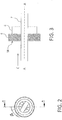
Fig. 1 shows a diagrammatic longitudinal section of a water disinfection device according to an embodiment of the invention. -
Fig. 2 is a diagrammatic cross-section of the device ofFig. 1 . -
Fig. 3 is a detail ofFig. 1 . -
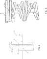
Fig. 4 shows a blade of the device according to one embodiment. -
Fig. 5 shows an axonometric view of the device according to an embodiment of the invention. -
Fig. 1 shows a cross section of awater disinfection device 1 with longitudinal axis A-A and comprising a cylindrical shell2, aninlet fitting 3, anoutlet fitting 4 and aninner assembly 5. - Said
assembly 5 provides a set of impact surfaces 18 for a water flow C entering thedevice 1 from the inlet fitting 3, thus defining a tortuous path for said water flow C. Said impact surfaces 18 are evenly distanced by a pitch p. - More in detail, the
assembly 5 comprises a plurality ofblades 6 which are supported by a common supportingtube 7 passing through a central axis of the blades (parallel to axis A-A).Theblades 6 are contained in a tubular passage orchannel 20, delimited by saidshell 2. The coupling between theblades 6 and the supportingtube 7 is relatively free, allowing vibration of theblades 6 relative to saidtube 7. - Each
blade 6 has a front face, facing the inlet fitting 3, which provides therespective impact surface 18. In the shown embodiment, theblades 6 are solid bodies with substantially no free space between one another, which means that the above mentioned pitch distance p is equal to the thickness ofblades 6 in the axial direction (direction of axis A-A). - In addition, each
blade 6 is rotated by a constant pitch angle β relatively to the preceding one in a given sense, so as to provide a tortuous path for the flow of water within thechannel 20, as visible inFig. 2 . Preferably, the pitch angle β is comprised in therange 10 to 45 degrees. In the example of theFig. 2 , said angle is 33 degrees. This angled arrangement defines a spiral path in thechannel 20, said path being delimited by theblades 6 and the inner surface of thecylindrical shell 2. - Preferably, the
blades 6 are substantially rectangular plates. - Preferably, the number of
blades 6 is comprised between 10 and 40, even more preferably between 20 and 30. In the example of the figure, the number ofblades 6 is 23. - The inlet fitting 3 comprises preferably an
opening 8 for the entry of water C, aconvergent section 9 and aportion 10 having a constant cross section. Saidportion 10 has aninlet surface 11 matching the outlet of theconvergent section 9 and anoutlet surface 12 facing thebladed assembly 5 and through which the water flow C is introduced into thechannel 20. - The
outlet fitting 4 comprises preferably a portion 13with a constant cross section, adivergent section 14 and anopening 15 for the outlet of water.Saidportion 13 has aninlet surface 16 facing the bladed assembly 5through which the water flow C leaves thespiral path 20 and anoutlet surface 17 matching the inlet of thedivergent section 9. - Preferably, the inlet fitting 3 and the outlet fitting 4 are identical.
- For a device having an internal diameter ranging from around 25.4 mm (1") to 50.8 mm (2"),the length of the deviceis preferably in the range 290 mm to 470 mm.
-
Fig. 5 shows a device, wherein theblades 6 are spaced one relative to the other andportions 7a of the supportingtube 7 between adjacent blades are contacted by the water flow. In the example of the figure, the blades are 11. - The
water disinfection device 1 works as follows. Wateris admittedthrough theinlet opening 8, passes through theconvergent portion 9 where it is accelerated and depressurized,and is introduced into the channel20 through thesubsequent portion 10. - Water follows the direction indicated by arrow C in
Fig. 1 and flows along the tortuous passage in the channel 20impacting against the surfaces18 of theblades 6, which induce a swirling motion. - The waterflow C leaving said tortuous passage is then introduced into the
portion 13 of the outlet fitting 4 and passes through thedivergent section 14 where it is pressurized. - The applicant has found that when the
device 1 is fed with water at appropriate flow rate and pressure, the outlet flow exhibits ultrasonic pressure waves generated during the passage through the bladed assembly 5.For example, a frequency of 20.48 kHz has been detected at the outlet of a 2" device according to the invention. Said measurement has been carried out by means of the frequency meter "Patterson Ultrasound detector D 200". - These waves are believed to be responsible of the above described effects, such as bacteria inhibition and reduced regrowth of microorganisms.
- As previously mentioned, a carrier frequency Fc can be defined as the frequency of impacts of the flow water against the sequence of blades 6 (hits/time), from inlet to outlet. Accordingly, given that n is the number of the
blades 6, v is the speed of water C, and len is the length of thepassage 20, from end to end of thebladed assembly 5, the carrier frequency Fc is:
- The length of the chamber len can be expressed as (n·a) wherein a is the thickness of the
blades 6 and assuming there is substantially no clearance between adjoiningblades 6, as inFig. 1 . - Consequently, the carrier frequency is given by the more simple formula:

- This relation can be used when designing the device, given that Fc is chosen in the preferred range of 100 to 200 Hz.
- A water treatment device according to
Fig. 1 has a nominal diameter of 2" (two inches) and comprises achannel 20 with a set ofblades 6 in the form of rectangular bars made of AISI 304 stainless steel. One of the blades is illustrated inFig. 4 . - A carrier frequency Fc = 160 Hz is selected. Based on Tables (1) and (2) above, a fundamental frequency f0 = 160 / 8.93 = 17.92 Hz is selected.
- The following relation exists between the fundamental frequency f0 and the features of the rectangular blade:

Fig. 4 ); L is the length of the blade; Y is the Young's modulus and p is the density. As the material is stainless steel, p = 7.87 kg/dm3 and Y = 196.000 N/mm2. It is assumed L = 53.8 mm. - In addition, the following relation exists between the thickness a of the blades and the above mentioned radius of gyration R:
- The thickness a can be calculated using the above equations (3) and (4). The radius R is calculated from (3) by applying the condition of f0 = 17.92 Hz, and then a is calculated from (4). In this example, one obtains a = 10.1 mm. Accordingly, a blade thickness of 10 mm is selected.
- The speed of water v can be calculated by using equation (2) which, in this example, leads to a speed of 1.61 m/s.
- The width W of the blade (
Fig. 4 ) can be calculated with numerical methods, assuming a preferred volumetric flow rate. The volumetric flow rate can be determined taking into account the need to avoid too large pressure drops. For example, in a 2" device the volumetric flow rate is preferably in therange 10 to 20 m3/h. Assuming that the flowrate is 10 m3/h, a width of 10 mm can be calculated. - The minimum activation water speed vmin and flowrate can also be calculated. The activation speed is the minimum speed to establish the ultrasonic pressure waves, according to the invention. Said minimum speed can be calculated from equation (2), replacing Fc with f0. Hence, in the present example, the minimum speed is:

- Said minimum speed corresponds, in the present example, to a minimum flowrate of about 19 liters/min.
- The number of blades depends on the pitch angle between the blades and the overall deviation imposed to the water flow. Preferably at least two full rotations (i.e. 720 degrees) are imposed to the water flow, in order to achieve the desired ultrasonic frequency. The pitch angle is preferably in the
range 10° to 45° (degrees). Then, by choosing a pitch angle of 30 degrees, the number of the blades n is 720 / 30 = 24. - The length of the device is calculated as a consequence. As the thickness of blades is 10 mm, the device is at least 240 mm long.
- A first test was carried out on water samples containing a concentration of bacteria of 100.000 CFU/mL (colony-forming unit per milliliter) at 22 °C and 51.200 CFU/mL at 36 °C. Said samples of water were transferred from a first container to a second container by means of a pump ensuring a flow rate of 10 mL/min and a pressure of 5 bar and by interposing the device according to the invention in the transfer line. Water analysis were performed immediately after the passage through said device (t=0). The applicant observed that:
- After the first passage of the water through the device, the bacteria load decreased significantly from 100.000 CFU/mL to 16.200 CFU/mL by carrying out the test at 22 °C (84% of efficiency) and from 51.200 CFU/mL to 4.200 CFU/mL by carrying out the test at 36 °C (92% of efficiency);
after the second passage of the water through the device, the bacteria load further decreased from 16.200 CFU/mL to 1.770 CFU/mL by carrying out the test at 22 °C (98% of efficiency) and from 4.200 CFU/mL to 1.740 CFU/mL by carrying out the test at 36 °C (97% of efficiency). - A second test was carried out on a water sample containing a concentration of bacteria of 3.600 CFU/mL at 36 °C. Water analysis were performed immediately after the passage through the device (t=0), and repeated after 3 days (t=3), 6days (t=6) and 10 days (t=10).
- The results are summarized in Table (3) below.
Table (3) Conc [CFU/mL] t=0 Conc [CFU/mL] t=3 Conc [CFU/mL] t=6 Conc [CFU/mL] t=10 Initial water 3.600 4.000 32.000 44.000 1 passage 20 30 510 8.700 2 passages 10 12 200 1.400 3 passages 6 - - - 4 passages 4 - - -
Claims (15)
- Method for disinfecting water, wherein ultrasonic pressure waves are induced into a flow of water.
- Method according to claim 1, wherein said ultrasonic waves have a frequency ranging from 20 to 100 kHz.
- Method according to claim 2, wherein said ultrasonic waveshave a frequencyranging from20 to 40 kHz.
- Method according to any of the preceding claims, wherein said ultrasonic waves are induced by a set of impact surfaces (18)aligned along the direction of the flow of water, each of said surfaces partially obstructing the passage of said flow of water.
- Method according to claim 4, wherein the impact surfaces (18)define a tortuous passage for the flow of water.
- Method according to claim 4 or 5, wherein a carrier frequency Fc of water impacting said surfacesis selected between 100 and 200 Hz, preferably 140 to 180 Hz and more preferably around 160 Hz, said carrier frequency beingdefined as Fc = v / p, wherein v is the speed of water and p is adistance between adjoiningsurfaces.
- Method according to any of the previous claims, wherein the method is carried out in a disinfection device (1) comprising a substantially tubular channel (20) where a plurality of blades (6) are arranged and provide said impact surfaces (18) for the water flow,
- Method according to claims 6 and 7, wherein the frequency fn of a selected mode of transversal vibration of said blades is equal to said carrier frequency Fc.
- Method according to claim 8, said selected mode of vibration being the first mode or a higher n-th mode according to the inner diameter of said tubular passage (20), and according to the following table:
n Inner diameter (mm) 1 up to 15.8 2 15.9 - 26.6 3 26.7 - 40.9 4 41 - 62.7 5 62.8 - 95.3 6 >95.3 - Method according to any of claims 7 to 9, wherein said blades are shaped as rods or bars, preferably rectangular bars.
- Method according to any of the previous claims, the method being carried out in a water disinfection device comprising a shell (2) acting as a wave guide.
- Water disinfection device for carrying out the method according to any of the previous claims, said device comprising a water channel (20) and a set of blades (6)arranged into said channel (20), said blades being arranged to induce ultrasonic pressure waves into water flowing through the passage.
- A device according to claim 12, comprising anouter shell (2)delimiting said water channel (20) and acting as a wave guide.
- Device according to claim 12 or 13, wherein said blades (6) are rotated one relative to another by a pitch angle (β), said angle being preferably comprised between 10 and 45 degrees and more preferably comprised between 27 and 33 degrees.
- Device according to any one of claims 12 to 14, wherein said pitch angle and its sense are constant along the sequence of the blades (6), so as a spiral path is defined.
Priority Applications (1)
| Application Number | Priority Date | Filing Date | Title |
|---|---|---|---|
| EP16472001.3A EP3208242B1 (en) | 2016-02-18 | 2016-02-18 | Ultrasound method for disinfecting water |
Applications Claiming Priority (1)
| Application Number | Priority Date | Filing Date | Title |
|---|---|---|---|
| EP16472001.3A EP3208242B1 (en) | 2016-02-18 | 2016-02-18 | Ultrasound method for disinfecting water |
Publications (2)
| Publication Number | Publication Date |
|---|---|
| EP3208242A1 true EP3208242A1 (en) | 2017-08-23 |
| EP3208242B1 EP3208242B1 (en) | 2020-05-06 |
Family
ID=55794928
Family Applications (1)
| Application Number | Title | Priority Date | Filing Date |
|---|---|---|---|
| EP16472001.3A Active EP3208242B1 (en) | 2016-02-18 | 2016-02-18 | Ultrasound method for disinfecting water |
Country Status (1)
| Country | Link |
|---|---|
| EP (1) | EP3208242B1 (en) |
Cited By (2)
| Publication number | Priority date | Publication date | Assignee | Title |
|---|---|---|---|---|
| IT202100011924A1 (en) | 2021-05-10 | 2022-11-10 | Treelium Sa | Electrochemical water treatment device |
| DK202201112A1 (en) * | 2022-12-08 | 2024-01-19 | Aquazit Aps | AQUAFIT - unit for converting lime molecules in the water |
Citations (5)
| Publication number | Priority date | Publication date | Assignee | Title |
|---|---|---|---|---|
| US20050058579A1 (en) * | 2003-09-16 | 2005-03-17 | Cline Amos E. | Acoustic energy transducer |
| FR2873041A1 (en) * | 2004-07-19 | 2006-01-20 | Jean Pierre Crespin | ULTRASONIC STERILIZER |
| US20100072143A1 (en) * | 2007-04-26 | 2010-03-25 | Bernard Jacobs | Water treatment system |
| WO2012003815A2 (en) * | 2010-07-07 | 2012-01-12 | Vysoké učeni technické v Brně | Device for killing microorganisms in liquids |
| JP2015123398A (en) * | 2013-12-26 | 2015-07-06 | 孝夫 野島 | Water sterilization device, vertical type multi-layer water sterilization device, and water sterilization method |
-
2016
- 2016-02-18 EP EP16472001.3A patent/EP3208242B1/en active Active
Patent Citations (5)
| Publication number | Priority date | Publication date | Assignee | Title |
|---|---|---|---|---|
| US20050058579A1 (en) * | 2003-09-16 | 2005-03-17 | Cline Amos E. | Acoustic energy transducer |
| FR2873041A1 (en) * | 2004-07-19 | 2006-01-20 | Jean Pierre Crespin | ULTRASONIC STERILIZER |
| US20100072143A1 (en) * | 2007-04-26 | 2010-03-25 | Bernard Jacobs | Water treatment system |
| WO2012003815A2 (en) * | 2010-07-07 | 2012-01-12 | Vysoké učeni technické v Brně | Device for killing microorganisms in liquids |
| JP2015123398A (en) * | 2013-12-26 | 2015-07-06 | 孝夫 野島 | Water sterilization device, vertical type multi-layer water sterilization device, and water sterilization method |
Cited By (3)
| Publication number | Priority date | Publication date | Assignee | Title |
|---|---|---|---|---|
| IT202100011924A1 (en) | 2021-05-10 | 2022-11-10 | Treelium Sa | Electrochemical water treatment device |
| DK202201112A1 (en) * | 2022-12-08 | 2024-01-19 | Aquazit Aps | AQUAFIT - unit for converting lime molecules in the water |
| DK181445B1 (en) * | 2022-12-08 | 2024-01-19 | Aquazit Aps | Aggregate for converting lime molecules into water |
Also Published As
| Publication number | Publication date |
|---|---|
| EP3208242B1 (en) | 2020-05-06 |
Similar Documents
| Publication | Publication Date | Title |
|---|---|---|
| US6379628B2 (en) | Pulsed electric field treatment system | |
| JP5408661B2 (en) | Ballast water treatment apparatus and ballast water treatment method | |
| US4086057A (en) | Ultrasonic disinfection system | |
| US20080292510A1 (en) | System and method for sterilization of a liquid | |
| Šarc et al. | Can rapid pressure decrease induced by supercavitation efficiently eradicate Legionella pneumophila bacteria? | |
| EP1954633A2 (en) | Method and apparatus for water treatment to eliminate aquatic organisms | |
| EP3321233A1 (en) | Method and device for in-stream aqueous medium treatment | |
| EP3208242B1 (en) | Ultrasound method for disinfecting water | |
| WO2018081868A1 (en) | Nanobubble generator | |
| US8936392B2 (en) | Hydrodynamic cavitation device | |
| US12552685B2 (en) | Water processing apparatus | |
| RU2183197C1 (en) | Water treatment apparatus | |
| CN103864161A (en) | Device for producing hydrodynamic cavitation by using tapered pore plate to inactivate microorganisms in water | |
| KR100919472B1 (en) | Equipment Treating Ballast Water | |
| KR20150117916A (en) | A device for recycling cutting oil using plasma | |
| DE102011114870A1 (en) | Device for treating a fluid | |
| CN101708875B (en) | Ultraviolet disinfection equipment for water treatment | |
| JP2010253415A (en) | Magnetic treatment apparatus | |
| WO2016010412A1 (en) | An apparatus for treating water using magnetic field | |
| US20230227334A1 (en) | Device for water treatment | |
| KR20070007811A (en) | Methods and apparatus for treating organic and / or biologically contaminated water and / or contaminated air with oxygen ions | |
| CN221420778U (en) | Ultrasonic device for ship ballast water treatment | |
| CN204918065U (en) | Ultrasonic wave sterilizer and drinking water preparation facilities, portable drinking water preparation system | |
| RU2445272C1 (en) | Method of decontaminating water with synergetic action | |
| RU2328449C2 (en) | Method and device for disinfecting drinking and sewage water |
Legal Events
| Date | Code | Title | Description |
|---|---|---|---|
| PUAI | Public reference made under article 153(3) epc to a published international application that has entered the european phase |
Free format text: ORIGINAL CODE: 0009012 |
|
| STAA | Information on the status of an ep patent application or granted ep patent |
Free format text: STATUS: THE APPLICATION HAS BEEN PUBLISHED |
|
| AK | Designated contracting states |
Kind code of ref document: A1 Designated state(s): AL AT BE BG CH CY CZ DE DK EE ES FI FR GB GR HR HU IE IS IT LI LT LU LV MC MK MT NL NO PL PT RO RS SE SI SK SM TR |
|
| AX | Request for extension of the european patent |
Extension state: BA ME |
|
| STAA | Information on the status of an ep patent application or granted ep patent |
Free format text: STATUS: REQUEST FOR EXAMINATION WAS MADE |
|
| 17P | Request for examination filed |
Effective date: 20180223 |
|
| RBV | Designated contracting states (corrected) |
Designated state(s): AL AT BE BG CH CY CZ DE DK EE ES FI FR GB GR HR HU IE IS IT LI LT LU LV MC MK MT NL NO PL PT RO RS SE SI SK SM TR |
|
| STAA | Information on the status of an ep patent application or granted ep patent |
Free format text: STATUS: EXAMINATION IS IN PROGRESS |
|
| 17Q | First examination report despatched |
Effective date: 20190910 |
|
| GRAJ | Information related to disapproval of communication of intention to grant by the applicant or resumption of examination proceedings by the epo deleted |
Free format text: ORIGINAL CODE: EPIDOSDIGR1 |
|
| GRAP | Despatch of communication of intention to grant a patent |
Free format text: ORIGINAL CODE: EPIDOSNIGR1 |
|
| GRAP | Despatch of communication of intention to grant a patent |
Free format text: ORIGINAL CODE: EPIDOSNIGR1 |
|
| STAA | Information on the status of an ep patent application or granted ep patent |
Free format text: STATUS: GRANT OF PATENT IS INTENDED |
|
| RIC1 | Information provided on ipc code assigned before grant |
Ipc: C02F 1/34 20060101AFI20191029BHEP Ipc: C02F 1/36 20060101ALN20191029BHEP |
|
| INTG | Intention to grant announced |
Effective date: 20191203 |
|
| RIC1 | Information provided on ipc code assigned before grant |
Ipc: C02F 1/34 20060101AFI20191122BHEP Ipc: C02F 1/36 20060101ALN20191122BHEP |
|
| GRAS | Grant fee paid |
Free format text: ORIGINAL CODE: EPIDOSNIGR3 |
|
| GRAA | (expected) grant |
Free format text: ORIGINAL CODE: 0009210 |
|
| STAA | Information on the status of an ep patent application or granted ep patent |
Free format text: STATUS: THE PATENT HAS BEEN GRANTED |
|
| AK | Designated contracting states |
Kind code of ref document: B1 Designated state(s): AL AT BE BG CH CY CZ DE DK EE ES FI FR GB GR HR HU IE IS IT LI LT LU LV MC MK MT NL NO PL PT RO RS SE SI SK SM TR |
|
| REG | Reference to a national code |
Ref country code: GB Ref legal event code: FG4D |
|
| REG | Reference to a national code |
Ref country code: AT Ref legal event code: REF Ref document number: 1266454 Country of ref document: AT Kind code of ref document: T Effective date: 20200515 Ref country code: CH Ref legal event code: EP |
|
| REG | Reference to a national code |
Ref country code: IE Ref legal event code: FG4D |
|
| REG | Reference to a national code |
Ref country code: DE Ref legal event code: R096 Ref document number: 602016035657 Country of ref document: DE |
|
| REG | Reference to a national code |
Ref country code: LT Ref legal event code: MG4D |
|
| REG | Reference to a national code |
Ref country code: NL Ref legal event code: MP Effective date: 20200506 |
|
| PG25 | Lapsed in a contracting state [announced via postgrant information from national office to epo] |
Ref country code: FI Free format text: LAPSE BECAUSE OF FAILURE TO SUBMIT A TRANSLATION OF THE DESCRIPTION OR TO PAY THE FEE WITHIN THE PRESCRIBED TIME-LIMIT Effective date: 20200506 Ref country code: PT Free format text: LAPSE BECAUSE OF FAILURE TO SUBMIT A TRANSLATION OF THE DESCRIPTION OR TO PAY THE FEE WITHIN THE PRESCRIBED TIME-LIMIT Effective date: 20200907 Ref country code: NO Free format text: LAPSE BECAUSE OF FAILURE TO SUBMIT A TRANSLATION OF THE DESCRIPTION OR TO PAY THE FEE WITHIN THE PRESCRIBED TIME-LIMIT Effective date: 20200806 Ref country code: IS Free format text: LAPSE BECAUSE OF FAILURE TO SUBMIT A TRANSLATION OF THE DESCRIPTION OR TO PAY THE FEE WITHIN THE PRESCRIBED TIME-LIMIT Effective date: 20200906 Ref country code: GR Free format text: LAPSE BECAUSE OF FAILURE TO SUBMIT A TRANSLATION OF THE DESCRIPTION OR TO PAY THE FEE WITHIN THE PRESCRIBED TIME-LIMIT Effective date: 20200807 Ref country code: LT Free format text: LAPSE BECAUSE OF FAILURE TO SUBMIT A TRANSLATION OF THE DESCRIPTION OR TO PAY THE FEE WITHIN THE PRESCRIBED TIME-LIMIT Effective date: 20200506 Ref country code: SE Free format text: LAPSE BECAUSE OF FAILURE TO SUBMIT A TRANSLATION OF THE DESCRIPTION OR TO PAY THE FEE WITHIN THE PRESCRIBED TIME-LIMIT Effective date: 20200506 |
|
| PG25 | Lapsed in a contracting state [announced via postgrant information from national office to epo] |
Ref country code: RS Free format text: LAPSE BECAUSE OF FAILURE TO SUBMIT A TRANSLATION OF THE DESCRIPTION OR TO PAY THE FEE WITHIN THE PRESCRIBED TIME-LIMIT Effective date: 20200506 Ref country code: HR Free format text: LAPSE BECAUSE OF FAILURE TO SUBMIT A TRANSLATION OF THE DESCRIPTION OR TO PAY THE FEE WITHIN THE PRESCRIBED TIME-LIMIT Effective date: 20200506 Ref country code: LV Free format text: LAPSE BECAUSE OF FAILURE TO SUBMIT A TRANSLATION OF THE DESCRIPTION OR TO PAY THE FEE WITHIN THE PRESCRIBED TIME-LIMIT Effective date: 20200506 |
|
| REG | Reference to a national code |
Ref country code: AT Ref legal event code: MK05 Ref document number: 1266454 Country of ref document: AT Kind code of ref document: T Effective date: 20200506 |
|
| PG25 | Lapsed in a contracting state [announced via postgrant information from national office to epo] |
Ref country code: AL Free format text: LAPSE BECAUSE OF FAILURE TO SUBMIT A TRANSLATION OF THE DESCRIPTION OR TO PAY THE FEE WITHIN THE PRESCRIBED TIME-LIMIT Effective date: 20200506 Ref country code: NL Free format text: LAPSE BECAUSE OF FAILURE TO SUBMIT A TRANSLATION OF THE DESCRIPTION OR TO PAY THE FEE WITHIN THE PRESCRIBED TIME-LIMIT Effective date: 20200506 |
|
| PG25 | Lapsed in a contracting state [announced via postgrant information from national office to epo] |
Ref country code: AT Free format text: LAPSE BECAUSE OF FAILURE TO SUBMIT A TRANSLATION OF THE DESCRIPTION OR TO PAY THE FEE WITHIN THE PRESCRIBED TIME-LIMIT Effective date: 20200506 Ref country code: DK Free format text: LAPSE BECAUSE OF FAILURE TO SUBMIT A TRANSLATION OF THE DESCRIPTION OR TO PAY THE FEE WITHIN THE PRESCRIBED TIME-LIMIT Effective date: 20200506 Ref country code: SM Free format text: LAPSE BECAUSE OF FAILURE TO SUBMIT A TRANSLATION OF THE DESCRIPTION OR TO PAY THE FEE WITHIN THE PRESCRIBED TIME-LIMIT Effective date: 20200506 Ref country code: EE Free format text: LAPSE BECAUSE OF FAILURE TO SUBMIT A TRANSLATION OF THE DESCRIPTION OR TO PAY THE FEE WITHIN THE PRESCRIBED TIME-LIMIT Effective date: 20200506 Ref country code: ES Free format text: LAPSE BECAUSE OF FAILURE TO SUBMIT A TRANSLATION OF THE DESCRIPTION OR TO PAY THE FEE WITHIN THE PRESCRIBED TIME-LIMIT Effective date: 20200506 Ref country code: RO Free format text: LAPSE BECAUSE OF FAILURE TO SUBMIT A TRANSLATION OF THE DESCRIPTION OR TO PAY THE FEE WITHIN THE PRESCRIBED TIME-LIMIT Effective date: 20200506 Ref country code: CZ Free format text: LAPSE BECAUSE OF FAILURE TO SUBMIT A TRANSLATION OF THE DESCRIPTION OR TO PAY THE FEE WITHIN THE PRESCRIBED TIME-LIMIT Effective date: 20200506 |
|
| REG | Reference to a national code |
Ref country code: DE Ref legal event code: R097 Ref document number: 602016035657 Country of ref document: DE |
|
| PG25 | Lapsed in a contracting state [announced via postgrant information from national office to epo] |
Ref country code: PL Free format text: LAPSE BECAUSE OF FAILURE TO SUBMIT A TRANSLATION OF THE DESCRIPTION OR TO PAY THE FEE WITHIN THE PRESCRIBED TIME-LIMIT Effective date: 20200506 Ref country code: SK Free format text: LAPSE BECAUSE OF FAILURE TO SUBMIT A TRANSLATION OF THE DESCRIPTION OR TO PAY THE FEE WITHIN THE PRESCRIBED TIME-LIMIT Effective date: 20200506 |
|
| PLBE | No opposition filed within time limit |
Free format text: ORIGINAL CODE: 0009261 |
|
| STAA | Information on the status of an ep patent application or granted ep patent |
Free format text: STATUS: NO OPPOSITION FILED WITHIN TIME LIMIT |
|
| 26N | No opposition filed |
Effective date: 20210209 |
|
| PGFP | Annual fee paid to national office [announced via postgrant information from national office to epo] |
Ref country code: FR Payment date: 20210204 Year of fee payment: 6 |
|
| PG25 | Lapsed in a contracting state [announced via postgrant information from national office to epo] |
Ref country code: SI Free format text: LAPSE BECAUSE OF FAILURE TO SUBMIT A TRANSLATION OF THE DESCRIPTION OR TO PAY THE FEE WITHIN THE PRESCRIBED TIME-LIMIT Effective date: 20200506 |
|
| REG | Reference to a national code |
Ref country code: DE Ref legal event code: R119 Ref document number: 602016035657 Country of ref document: DE |
|
| PG25 | Lapsed in a contracting state [announced via postgrant information from national office to epo] |
Ref country code: MC Free format text: LAPSE BECAUSE OF FAILURE TO SUBMIT A TRANSLATION OF THE DESCRIPTION OR TO PAY THE FEE WITHIN THE PRESCRIBED TIME-LIMIT Effective date: 20200506 |
|
| REG | Reference to a national code |
Ref country code: BE Ref legal event code: MM Effective date: 20210228 |
|
| PG25 | Lapsed in a contracting state [announced via postgrant information from national office to epo] |
Ref country code: LU Free format text: LAPSE BECAUSE OF NON-PAYMENT OF DUE FEES Effective date: 20210218 |
|
| PG25 | Lapsed in a contracting state [announced via postgrant information from national office to epo] |
Ref country code: DE Free format text: LAPSE BECAUSE OF NON-PAYMENT OF DUE FEES Effective date: 20210901 Ref country code: IE Free format text: LAPSE BECAUSE OF NON-PAYMENT OF DUE FEES Effective date: 20210218 |
|
| PG25 | Lapsed in a contracting state [announced via postgrant information from national office to epo] |
Ref country code: BE Free format text: LAPSE BECAUSE OF NON-PAYMENT OF DUE FEES Effective date: 20210228 |
|
| PG25 | Lapsed in a contracting state [announced via postgrant information from national office to epo] |
Ref country code: FR Free format text: LAPSE BECAUSE OF NON-PAYMENT OF DUE FEES Effective date: 20220228 |
|
| PGFP | Annual fee paid to national office [announced via postgrant information from national office to epo] |
Ref country code: BG Payment date: 20230206 Year of fee payment: 8 |
|
| PG25 | Lapsed in a contracting state [announced via postgrant information from national office to epo] |
Ref country code: HU Free format text: LAPSE BECAUSE OF FAILURE TO SUBMIT A TRANSLATION OF THE DESCRIPTION OR TO PAY THE FEE WITHIN THE PRESCRIBED TIME-LIMIT; INVALID AB INITIO Effective date: 20160218 |
|
| PG25 | Lapsed in a contracting state [announced via postgrant information from national office to epo] |
Ref country code: CY Free format text: LAPSE BECAUSE OF FAILURE TO SUBMIT A TRANSLATION OF THE DESCRIPTION OR TO PAY THE FEE WITHIN THE PRESCRIBED TIME-LIMIT Effective date: 20200506 |
|
| PG25 | Lapsed in a contracting state [announced via postgrant information from national office to epo] |
Ref country code: MK Free format text: LAPSE BECAUSE OF FAILURE TO SUBMIT A TRANSLATION OF THE DESCRIPTION OR TO PAY THE FEE WITHIN THE PRESCRIBED TIME-LIMIT Effective date: 20200506 |
|
| PG25 | Lapsed in a contracting state [announced via postgrant information from national office to epo] |
Ref country code: MT Free format text: LAPSE BECAUSE OF FAILURE TO SUBMIT A TRANSLATION OF THE DESCRIPTION OR TO PAY THE FEE WITHIN THE PRESCRIBED TIME-LIMIT Effective date: 20200506 |
|
| PG25 | Lapsed in a contracting state [announced via postgrant information from national office to epo] |
Ref country code: BG Free format text: LAPSE BECAUSE OF NON-PAYMENT OF DUE FEES Effective date: 20240218 |
|
| PG25 | Lapsed in a contracting state [announced via postgrant information from national office to epo] |
Ref country code: BG Free format text: LAPSE BECAUSE OF NON-PAYMENT OF DUE FEES Effective date: 20240218 |
|
| PG25 | Lapsed in a contracting state [announced via postgrant information from national office to epo] |
Ref country code: TR Free format text: LAPSE BECAUSE OF FAILURE TO SUBMIT A TRANSLATION OF THE DESCRIPTION OR TO PAY THE FEE WITHIN THE PRESCRIBED TIME-LIMIT Effective date: 20200506 |
|
| REG | Reference to a national code |
Ref country code: CH Ref legal event code: U11 Free format text: ST27 STATUS EVENT CODE: U-0-0-U10-U11 (AS PROVIDED BY THE NATIONAL OFFICE) Effective date: 20260301 |
|
| PGFP | Annual fee paid to national office [announced via postgrant information from national office to epo] |
Ref country code: GB Payment date: 20260219 Year of fee payment: 11 |
|
| PGFP | Annual fee paid to national office [announced via postgrant information from national office to epo] |
Ref country code: IT Payment date: 20260219 Year of fee payment: 11 |
|
| PGFP | Annual fee paid to national office [announced via postgrant information from national office to epo] |
Ref country code: CH Payment date: 20260301 Year of fee payment: 11 |