EP3208137B1 - Electric vehicle charging station with integrated camera - Google Patents
Electric vehicle charging station with integrated camera Download PDFInfo
- Publication number
- EP3208137B1 EP3208137B1 EP17151808.7A EP17151808A EP3208137B1 EP 3208137 B1 EP3208137 B1 EP 3208137B1 EP 17151808 A EP17151808 A EP 17151808A EP 3208137 B1 EP3208137 B1 EP 3208137B1
- Authority
- EP
- European Patent Office
- Prior art keywords
- camera
- evse
- charging station
- smart
- smart evse
- Prior art date
- Legal status (The legal status is an assumption and is not a legal conclusion. Google has not performed a legal analysis and makes no representation as to the accuracy of the status listed.)
- Active
Links
- 238000004891 communication Methods 0.000 claims description 53
- 238000000034 method Methods 0.000 claims description 28
- 230000006870 function Effects 0.000 claims description 14
- 238000012544 monitoring process Methods 0.000 description 13
- 238000012986 modification Methods 0.000 description 9
- 230000004048 modification Effects 0.000 description 9
- 230000001413 cellular effect Effects 0.000 description 8
- 230000008569 process Effects 0.000 description 8
- 230000008901 benefit Effects 0.000 description 7
- 238000012545 processing Methods 0.000 description 5
- 238000010586 diagram Methods 0.000 description 4
- 238000010191 image analysis Methods 0.000 description 4
- 238000004458 analytical method Methods 0.000 description 3
- 238000013475 authorization Methods 0.000 description 3
- 230000005540 biological transmission Effects 0.000 description 3
- 238000009434 installation Methods 0.000 description 3
- 239000000463 material Substances 0.000 description 3
- 238000012546 transfer Methods 0.000 description 3
- 230000003213 activating effect Effects 0.000 description 2
- 238000007792 addition Methods 0.000 description 2
- 238000013500 data storage Methods 0.000 description 2
- 238000001514 detection method Methods 0.000 description 2
- 238000006467 substitution reaction Methods 0.000 description 2
- 230000004913 activation Effects 0.000 description 1
- 238000000429 assembly Methods 0.000 description 1
- 230000000712 assembly Effects 0.000 description 1
- 230000008878 coupling Effects 0.000 description 1
- 238000010168 coupling process Methods 0.000 description 1
- 238000005859 coupling reaction Methods 0.000 description 1
- 238000012217 deletion Methods 0.000 description 1
- 230000037430 deletion Effects 0.000 description 1
- 230000001419 dependent effect Effects 0.000 description 1
- 238000005516 engineering process Methods 0.000 description 1
- 230000010365 information processing Effects 0.000 description 1
- 230000010354 integration Effects 0.000 description 1
- 238000007726 management method Methods 0.000 description 1
- 230000004297 night vision Effects 0.000 description 1
- 230000002265 prevention Effects 0.000 description 1
- 230000008707 rearrangement Effects 0.000 description 1
- 230000010076 replication Effects 0.000 description 1
- 239000007858 starting material Substances 0.000 description 1
- 238000013024 troubleshooting Methods 0.000 description 1
- 238000012795 verification Methods 0.000 description 1
Images


Classifications
-
- B—PERFORMING OPERATIONS; TRANSPORTING
- B60—VEHICLES IN GENERAL
- B60L—PROPULSION OF ELECTRICALLY-PROPELLED VEHICLES; SUPPLYING ELECTRIC POWER FOR AUXILIARY EQUIPMENT OF ELECTRICALLY-PROPELLED VEHICLES; ELECTRODYNAMIC BRAKE SYSTEMS FOR VEHICLES IN GENERAL; MAGNETIC SUSPENSION OR LEVITATION FOR VEHICLES; MONITORING OPERATING VARIABLES OF ELECTRICALLY-PROPELLED VEHICLES; ELECTRIC SAFETY DEVICES FOR ELECTRICALLY-PROPELLED VEHICLES
- B60L53/00—Methods of charging batteries, specially adapted for electric vehicles; Charging stations or on-board charging equipment therefor; Exchange of energy storage elements in electric vehicles
- B60L53/10—Methods of charging batteries, specially adapted for electric vehicles; Charging stations or on-board charging equipment therefor; Exchange of energy storage elements in electric vehicles characterised by the energy transfer between the charging station and the vehicle
- B60L53/14—Conductive energy transfer
-
- B—PERFORMING OPERATIONS; TRANSPORTING
- B60—VEHICLES IN GENERAL
- B60L—PROPULSION OF ELECTRICALLY-PROPELLED VEHICLES; SUPPLYING ELECTRIC POWER FOR AUXILIARY EQUIPMENT OF ELECTRICALLY-PROPELLED VEHICLES; ELECTRODYNAMIC BRAKE SYSTEMS FOR VEHICLES IN GENERAL; MAGNETIC SUSPENSION OR LEVITATION FOR VEHICLES; MONITORING OPERATING VARIABLES OF ELECTRICALLY-PROPELLED VEHICLES; ELECTRIC SAFETY DEVICES FOR ELECTRICALLY-PROPELLED VEHICLES
- B60L53/00—Methods of charging batteries, specially adapted for electric vehicles; Charging stations or on-board charging equipment therefor; Exchange of energy storage elements in electric vehicles
- B60L53/30—Constructional details of charging stations
- B60L53/305—Communication interfaces
-
- B—PERFORMING OPERATIONS; TRANSPORTING
- B60—VEHICLES IN GENERAL
- B60L—PROPULSION OF ELECTRICALLY-PROPELLED VEHICLES; SUPPLYING ELECTRIC POWER FOR AUXILIARY EQUIPMENT OF ELECTRICALLY-PROPELLED VEHICLES; ELECTRODYNAMIC BRAKE SYSTEMS FOR VEHICLES IN GENERAL; MAGNETIC SUSPENSION OR LEVITATION FOR VEHICLES; MONITORING OPERATING VARIABLES OF ELECTRICALLY-PROPELLED VEHICLES; ELECTRIC SAFETY DEVICES FOR ELECTRICALLY-PROPELLED VEHICLES
- B60L53/00—Methods of charging batteries, specially adapted for electric vehicles; Charging stations or on-board charging equipment therefor; Exchange of energy storage elements in electric vehicles
- B60L53/30—Constructional details of charging stations
- B60L53/31—Charging columns specially adapted for electric vehicles
-
- B—PERFORMING OPERATIONS; TRANSPORTING
- B60—VEHICLES IN GENERAL
- B60L—PROPULSION OF ELECTRICALLY-PROPELLED VEHICLES; SUPPLYING ELECTRIC POWER FOR AUXILIARY EQUIPMENT OF ELECTRICALLY-PROPELLED VEHICLES; ELECTRODYNAMIC BRAKE SYSTEMS FOR VEHICLES IN GENERAL; MAGNETIC SUSPENSION OR LEVITATION FOR VEHICLES; MONITORING OPERATING VARIABLES OF ELECTRICALLY-PROPELLED VEHICLES; ELECTRIC SAFETY DEVICES FOR ELECTRICALLY-PROPELLED VEHICLES
- B60L53/00—Methods of charging batteries, specially adapted for electric vehicles; Charging stations or on-board charging equipment therefor; Exchange of energy storage elements in electric vehicles
- B60L53/60—Monitoring or controlling charging stations
- B60L53/65—Monitoring or controlling charging stations involving identification of vehicles or their battery types
-
- B—PERFORMING OPERATIONS; TRANSPORTING
- B60—VEHICLES IN GENERAL
- B60L—PROPULSION OF ELECTRICALLY-PROPELLED VEHICLES; SUPPLYING ELECTRIC POWER FOR AUXILIARY EQUIPMENT OF ELECTRICALLY-PROPELLED VEHICLES; ELECTRODYNAMIC BRAKE SYSTEMS FOR VEHICLES IN GENERAL; MAGNETIC SUSPENSION OR LEVITATION FOR VEHICLES; MONITORING OPERATING VARIABLES OF ELECTRICALLY-PROPELLED VEHICLES; ELECTRIC SAFETY DEVICES FOR ELECTRICALLY-PROPELLED VEHICLES
- B60L53/00—Methods of charging batteries, specially adapted for electric vehicles; Charging stations or on-board charging equipment therefor; Exchange of energy storage elements in electric vehicles
- B60L53/60—Monitoring or controlling charging stations
- B60L53/66—Data transfer between charging stations and vehicles
- B60L53/665—Methods related to measuring, billing or payment
-
- G—PHYSICS
- G06—COMPUTING; CALCULATING OR COUNTING
- G06Q—INFORMATION AND COMMUNICATION TECHNOLOGY [ICT] SPECIALLY ADAPTED FOR ADMINISTRATIVE, COMMERCIAL, FINANCIAL, MANAGERIAL OR SUPERVISORY PURPOSES; SYSTEMS OR METHODS SPECIALLY ADAPTED FOR ADMINISTRATIVE, COMMERCIAL, FINANCIAL, MANAGERIAL OR SUPERVISORY PURPOSES, NOT OTHERWISE PROVIDED FOR
- G06Q20/00—Payment architectures, schemes or protocols
- G06Q20/08—Payment architectures
- G06Q20/14—Payment architectures specially adapted for billing systems
- G06Q20/145—Payments according to the detected use or quantity
-
- G—PHYSICS
- G06—COMPUTING; CALCULATING OR COUNTING
- G06Q—INFORMATION AND COMMUNICATION TECHNOLOGY [ICT] SPECIALLY ADAPTED FOR ADMINISTRATIVE, COMMERCIAL, FINANCIAL, MANAGERIAL OR SUPERVISORY PURPOSES; SYSTEMS OR METHODS SPECIALLY ADAPTED FOR ADMINISTRATIVE, COMMERCIAL, FINANCIAL, MANAGERIAL OR SUPERVISORY PURPOSES, NOT OTHERWISE PROVIDED FOR
- G06Q20/00—Payment architectures, schemes or protocols
- G06Q20/30—Payment architectures, schemes or protocols characterised by the use of specific devices or networks
- G06Q20/34—Payment architectures, schemes or protocols characterised by the use of specific devices or networks using cards, e.g. integrated circuit [IC] cards or magnetic cards
-
- G—PHYSICS
- G06—COMPUTING; CALCULATING OR COUNTING
- G06Q—INFORMATION AND COMMUNICATION TECHNOLOGY [ICT] SPECIALLY ADAPTED FOR ADMINISTRATIVE, COMMERCIAL, FINANCIAL, MANAGERIAL OR SUPERVISORY PURPOSES; SYSTEMS OR METHODS SPECIALLY ADAPTED FOR ADMINISTRATIVE, COMMERCIAL, FINANCIAL, MANAGERIAL OR SUPERVISORY PURPOSES, NOT OTHERWISE PROVIDED FOR
- G06Q20/00—Payment architectures, schemes or protocols
- G06Q20/38—Payment protocols; Details thereof
- G06Q20/40—Authorisation, e.g. identification of payer or payee, verification of customer or shop credentials; Review and approval of payers, e.g. check credit lines or negative lists
- G06Q20/401—Transaction verification
- G06Q20/4012—Verifying personal identification numbers [PIN]
-
- G—PHYSICS
- G06—COMPUTING; CALCULATING OR COUNTING
- G06Q—INFORMATION AND COMMUNICATION TECHNOLOGY [ICT] SPECIALLY ADAPTED FOR ADMINISTRATIVE, COMMERCIAL, FINANCIAL, MANAGERIAL OR SUPERVISORY PURPOSES; SYSTEMS OR METHODS SPECIALLY ADAPTED FOR ADMINISTRATIVE, COMMERCIAL, FINANCIAL, MANAGERIAL OR SUPERVISORY PURPOSES, NOT OTHERWISE PROVIDED FOR
- G06Q20/00—Payment architectures, schemes or protocols
- G06Q20/38—Payment protocols; Details thereof
- G06Q20/40—Authorisation, e.g. identification of payer or payee, verification of customer or shop credentials; Review and approval of payers, e.g. check credit lines or negative lists
- G06Q20/401—Transaction verification
- G06Q20/4014—Identity check for transactions
- G06Q20/40145—Biometric identity checks
-
- G—PHYSICS
- G06—COMPUTING; CALCULATING OR COUNTING
- G06V—IMAGE OR VIDEO RECOGNITION OR UNDERSTANDING
- G06V40/00—Recognition of biometric, human-related or animal-related patterns in image or video data
- G06V40/10—Human or animal bodies, e.g. vehicle occupants or pedestrians; Body parts, e.g. hands
-
- G—PHYSICS
- G07—CHECKING-DEVICES
- G07F—COIN-FREED OR LIKE APPARATUS
- G07F15/00—Coin-freed apparatus with meter-controlled dispensing of liquid, gas or electricity
- G07F15/003—Coin-freed apparatus with meter-controlled dispensing of liquid, gas or electricity for electricity
- G07F15/005—Coin-freed apparatus with meter-controlled dispensing of liquid, gas or electricity for electricity dispensed for the electrical charging of vehicles
-
- G—PHYSICS
- G07—CHECKING-DEVICES
- G07F—COIN-FREED OR LIKE APPARATUS
- G07F7/00—Mechanisms actuated by objects other than coins to free or to actuate vending, hiring, coin or paper currency dispensing or refunding apparatus
- G07F7/08—Mechanisms actuated by objects other than coins to free or to actuate vending, hiring, coin or paper currency dispensing or refunding apparatus by coded identity card or credit card or other personal identification means
- G07F7/10—Mechanisms actuated by objects other than coins to free or to actuate vending, hiring, coin or paper currency dispensing or refunding apparatus by coded identity card or credit card or other personal identification means together with a coded signal, e.g. in the form of personal identification information, like personal identification number [PIN] or biometric data
- G07F7/1025—Identification of user by a PIN code
-
- H—ELECTRICITY
- H04—ELECTRIC COMMUNICATION TECHNIQUE
- H04N—PICTORIAL COMMUNICATION, e.g. TELEVISION
- H04N23/00—Cameras or camera modules comprising electronic image sensors; Control thereof
- H04N23/50—Constructional details
- H04N23/51—Housings
-
- H—ELECTRICITY
- H04—ELECTRIC COMMUNICATION TECHNIQUE
- H04N—PICTORIAL COMMUNICATION, e.g. TELEVISION
- H04N5/00—Details of television systems
- H04N5/76—Television signal recording
- H04N5/765—Interface circuits between an apparatus for recording and another apparatus
- H04N5/77—Interface circuits between an apparatus for recording and another apparatus between a recording apparatus and a television camera
- H04N5/772—Interface circuits between an apparatus for recording and another apparatus between a recording apparatus and a television camera the recording apparatus and the television camera being placed in the same enclosure
-
- H—ELECTRICITY
- H04—ELECTRIC COMMUNICATION TECHNIQUE
- H04N—PICTORIAL COMMUNICATION, e.g. TELEVISION
- H04N7/00—Television systems
- H04N7/18—Closed-circuit television [CCTV] systems, i.e. systems in which the video signal is not broadcast
-
- H—ELECTRICITY
- H04—ELECTRIC COMMUNICATION TECHNIQUE
- H04N—PICTORIAL COMMUNICATION, e.g. TELEVISION
- H04N7/00—Television systems
- H04N7/18—Closed-circuit television [CCTV] systems, i.e. systems in which the video signal is not broadcast
- H04N7/183—Closed-circuit television [CCTV] systems, i.e. systems in which the video signal is not broadcast for receiving images from a single remote source
-
- B—PERFORMING OPERATIONS; TRANSPORTING
- B60—VEHICLES IN GENERAL
- B60L—PROPULSION OF ELECTRICALLY-PROPELLED VEHICLES; SUPPLYING ELECTRIC POWER FOR AUXILIARY EQUIPMENT OF ELECTRICALLY-PROPELLED VEHICLES; ELECTRODYNAMIC BRAKE SYSTEMS FOR VEHICLES IN GENERAL; MAGNETIC SUSPENSION OR LEVITATION FOR VEHICLES; MONITORING OPERATING VARIABLES OF ELECTRICALLY-PROPELLED VEHICLES; ELECTRIC SAFETY DEVICES FOR ELECTRICALLY-PROPELLED VEHICLES
- B60L2270/00—Problem solutions or means not otherwise provided for
- B60L2270/30—Preventing theft during charging
-
- Y—GENERAL TAGGING OF NEW TECHNOLOGICAL DEVELOPMENTS; GENERAL TAGGING OF CROSS-SECTIONAL TECHNOLOGIES SPANNING OVER SEVERAL SECTIONS OF THE IPC; TECHNICAL SUBJECTS COVERED BY FORMER USPC CROSS-REFERENCE ART COLLECTIONS [XRACs] AND DIGESTS
- Y02—TECHNOLOGIES OR APPLICATIONS FOR MITIGATION OR ADAPTATION AGAINST CLIMATE CHANGE
- Y02T—CLIMATE CHANGE MITIGATION TECHNOLOGIES RELATED TO TRANSPORTATION
- Y02T10/00—Road transport of goods or passengers
- Y02T10/60—Other road transportation technologies with climate change mitigation effect
- Y02T10/70—Energy storage systems for electromobility, e.g. batteries
-
- Y—GENERAL TAGGING OF NEW TECHNOLOGICAL DEVELOPMENTS; GENERAL TAGGING OF CROSS-SECTIONAL TECHNOLOGIES SPANNING OVER SEVERAL SECTIONS OF THE IPC; TECHNICAL SUBJECTS COVERED BY FORMER USPC CROSS-REFERENCE ART COLLECTIONS [XRACs] AND DIGESTS
- Y02—TECHNOLOGIES OR APPLICATIONS FOR MITIGATION OR ADAPTATION AGAINST CLIMATE CHANGE
- Y02T—CLIMATE CHANGE MITIGATION TECHNOLOGIES RELATED TO TRANSPORTATION
- Y02T10/00—Road transport of goods or passengers
- Y02T10/60—Other road transportation technologies with climate change mitigation effect
- Y02T10/7072—Electromobility specific charging systems or methods for batteries, ultracapacitors, supercapacitors or double-layer capacitors
-
- Y—GENERAL TAGGING OF NEW TECHNOLOGICAL DEVELOPMENTS; GENERAL TAGGING OF CROSS-SECTIONAL TECHNOLOGIES SPANNING OVER SEVERAL SECTIONS OF THE IPC; TECHNICAL SUBJECTS COVERED BY FORMER USPC CROSS-REFERENCE ART COLLECTIONS [XRACs] AND DIGESTS
- Y02—TECHNOLOGIES OR APPLICATIONS FOR MITIGATION OR ADAPTATION AGAINST CLIMATE CHANGE
- Y02T—CLIMATE CHANGE MITIGATION TECHNOLOGIES RELATED TO TRANSPORTATION
- Y02T90/00—Enabling technologies or technologies with a potential or indirect contribution to GHG emissions mitigation
- Y02T90/10—Technologies relating to charging of electric vehicles
- Y02T90/12—Electric charging stations
-
- Y—GENERAL TAGGING OF NEW TECHNOLOGICAL DEVELOPMENTS; GENERAL TAGGING OF CROSS-SECTIONAL TECHNOLOGIES SPANNING OVER SEVERAL SECTIONS OF THE IPC; TECHNICAL SUBJECTS COVERED BY FORMER USPC CROSS-REFERENCE ART COLLECTIONS [XRACs] AND DIGESTS
- Y02—TECHNOLOGIES OR APPLICATIONS FOR MITIGATION OR ADAPTATION AGAINST CLIMATE CHANGE
- Y02T—CLIMATE CHANGE MITIGATION TECHNOLOGIES RELATED TO TRANSPORTATION
- Y02T90/00—Enabling technologies or technologies with a potential or indirect contribution to GHG emissions mitigation
- Y02T90/10—Technologies relating to charging of electric vehicles
- Y02T90/14—Plug-in electric vehicles
-
- Y—GENERAL TAGGING OF NEW TECHNOLOGICAL DEVELOPMENTS; GENERAL TAGGING OF CROSS-SECTIONAL TECHNOLOGIES SPANNING OVER SEVERAL SECTIONS OF THE IPC; TECHNICAL SUBJECTS COVERED BY FORMER USPC CROSS-REFERENCE ART COLLECTIONS [XRACs] AND DIGESTS
- Y02—TECHNOLOGIES OR APPLICATIONS FOR MITIGATION OR ADAPTATION AGAINST CLIMATE CHANGE
- Y02T—CLIMATE CHANGE MITIGATION TECHNOLOGIES RELATED TO TRANSPORTATION
- Y02T90/00—Enabling technologies or technologies with a potential or indirect contribution to GHG emissions mitigation
- Y02T90/10—Technologies relating to charging of electric vehicles
- Y02T90/16—Information or communication technologies improving the operation of electric vehicles
- Y02T90/167—Systems integrating technologies related to power network operation and communication or information technologies for supporting the interoperability of electric or hybrid vehicles, i.e. smartgrids as interface for battery charging of electric vehicles [EV] or hybrid vehicles [HEV]
-
- Y—GENERAL TAGGING OF NEW TECHNOLOGICAL DEVELOPMENTS; GENERAL TAGGING OF CROSS-SECTIONAL TECHNOLOGIES SPANNING OVER SEVERAL SECTIONS OF THE IPC; TECHNICAL SUBJECTS COVERED BY FORMER USPC CROSS-REFERENCE ART COLLECTIONS [XRACs] AND DIGESTS
- Y04—INFORMATION OR COMMUNICATION TECHNOLOGIES HAVING AN IMPACT ON OTHER TECHNOLOGY AREAS
- Y04S—SYSTEMS INTEGRATING TECHNOLOGIES RELATED TO POWER NETWORK OPERATION, COMMUNICATION OR INFORMATION TECHNOLOGIES FOR IMPROVING THE ELECTRICAL POWER GENERATION, TRANSMISSION, DISTRIBUTION, MANAGEMENT OR USAGE, i.e. SMART GRIDS
- Y04S30/00—Systems supporting specific end-user applications in the sector of transportation
- Y04S30/10—Systems supporting the interoperability of electric or hybrid vehicles
- Y04S30/12—Remote or cooperative charging
-
- Y—GENERAL TAGGING OF NEW TECHNOLOGICAL DEVELOPMENTS; GENERAL TAGGING OF CROSS-SECTIONAL TECHNOLOGIES SPANNING OVER SEVERAL SECTIONS OF THE IPC; TECHNICAL SUBJECTS COVERED BY FORMER USPC CROSS-REFERENCE ART COLLECTIONS [XRACs] AND DIGESTS
- Y04—INFORMATION OR COMMUNICATION TECHNOLOGIES HAVING AN IMPACT ON OTHER TECHNOLOGY AREAS
- Y04S—SYSTEMS INTEGRATING TECHNOLOGIES RELATED TO POWER NETWORK OPERATION, COMMUNICATION OR INFORMATION TECHNOLOGIES FOR IMPROVING THE ELECTRICAL POWER GENERATION, TRANSMISSION, DISTRIBUTION, MANAGEMENT OR USAGE, i.e. SMART GRIDS
- Y04S30/00—Systems supporting specific end-user applications in the sector of transportation
- Y04S30/10—Systems supporting the interoperability of electric or hybrid vehicles
- Y04S30/14—Details associated with the interoperability, e.g. vehicle recognition, authentication, identification or billing
Definitions
- the present disclosure generally relates to electric vehicle charging stations and the invention more specifically relates to a smart Electric Vehicle Supply Equipment, EVSE, charging station.
- EVSE Electric Vehicle Supply Equipment
- Electric vehicle charging stations such as smart electric vehicle charging stations are rapidly growing in popularity. More features are being incorporated into electric vehicle charging stations. For example, there are now messaging enabled electric vehicle charging stations that have built-in-communication modules. Such electric vehicle charging stations allow wireless communications of charging data to a server over a network.
- Conducting monetary transactions through mobile devices is known.
- Human sale points allow customers to purchase products and services using the customers' financial information.
- credit card based monetary transactions may be carried out by systems that can either read data from a magnetic strap attached to the card enabling the system to read details of the card for identification or by mechanically inputting the card number and other card details such as the name of the card owner and the expiry date of the card, which are usually printed or engraved on one surface of the card as well as the Card Verification Value Code (CVV or CVC) which is usually printed or engraved in the back surface of the card.
- CVV or CVC Card Verification Value Code
- electric vehicle charging stations cannot be used for conducting or managing such monetary transactions using customers' financial information.
- EP 2 514 624 A2 generally describes a method and system for authorizing the charging of an electric vehicle's batteries based on biometric identity information.
- the system relates the preamble of claim 1.
- the object of the present invention is in particular to provide an EVSE charging station which allows electric vehicle charging stations owners to charge for services in a safe and secure environment without deploying additional equipment.
- This object is solved by claim 1 and further advantages embodiments and improvements of the invention are listed in the dependent claims.
- the present disclosure generally relates to an electric vehicle charging station including built-in-cameras to allow video and pictures taken by the camera to be transmitted to a server or a mobile phone and stored on the electric vehicle charging station and processed locally as camera or image data for performing various camera functions such as authentication, security monitoring, motion detection etc.
- authentication information is received at the electric vehicle charging station and compared to acquired camera or image data for user identification or payment authentication.
- the electric vehicle charging station usage information is stored and communicated based on the authentication information and the acquired camera or image data to a server via a communications network.
- Electric vehicle charging station usage information includes a specific time when the electric vehicle charging station is used and an amount of energy used at the specific time.
- user identification, tamper deterrence, physical security of a parking lot and home garage security and monitoring may be done through an electric vehicle charging station of the present invention by using one or more cameras.
- One of ordinary skill in the art appreciates that such a camera system can be configured to be integrated in different environments where security, monitoring, identification or authentication is needed, for example, in a parking lot and a home garage installations of the electric vehicle charging station.
- a smart Electric Vehicle Supply Equipment comprises a networked on-charging station camera unit disposed either internally to the smart EVSE or connected externally on the smart EVSE.
- the camera unit may include at least one of a video camera and a still image camera.
- a smart Electric Vehicle Supply Equipment comprises a body having an exterior surface and a camera unit integrated with the body.
- the camera unit has a camera disposed on the exterior surface.
- the camera is communicatively coupled to a server via a communications network.
- the camera unit includes a processor configured to receive authentication information of a user of the smart EVSE over the communications network and a storage device configured to store the authentication information locally at the smart EVSE and store EVSE usage information.
- the processor is configured to compare the stored authentication information with information acquired from the camera to ascertain an identity of the user of the smart EVSE.
- a still and/or video camera with a smart EVSE.
- the camera may be provided internally to the smart EVSE or connected externally.
- the smart EVSE also provides means of communications of the camera information.
- a camera connection to a server or a mobile device may enable private communications to a specific point or public infrastructure may be used to connect the camera data to the Internet or other networked communications system.
- FIG. 1 illustrates a schematic diagram of a smart Electric Vehicle Supply Equipment (EVSE) 10 including a networked on-charging station camera unit 12 not in accordance with the present invention.
- the networked on-charging station camera unit 12 may be disposed either internally to the smart EVSE 10 or connected externally on the smart EVSE 10.
- the networked on-charging station camera unit 12 may include a built-in video camera 15 and/or a built-in still image camera 17.
- the smart EVSE 10 allows pictures taken by the built-in-cameras to be displayed on a screen and stored on the smart EVSE 10 and wirelessly or otherwise transmitted as digital photos or digital video files.
- Examples of the built-in video camera 15 include a video recorder that may be a high definition (HD) video recorder capable of recording 1080p and/or 720p video at 30 frames per second.
- the video recorder may alternatively be a standard definition video recorder limited to recording in lower resolutions, such as a video graphics array (VGA) resolution of 640 ⁇ 480.
- the video recorder may be provided by Premier, Chicony, Ability, Foxlink, IAC, or the like. A person skilled in the pertinent art would appreciate that other suitable video recorders may be readily deployed based on the specific implementation..
- the server 27 may be an EVSE server or a server that is specifically configured for payment or security.
- the acquired camera or image data 22 may reach the server 27 by way of public networks, private networks, or a combination of both.
- the image data, or information derived from the acquired camera or image data 22 may be (but is not required) made available to the users' mobile device 35 or other computing device over the network 30.
- the server 27 may store and report EVSE usage information associated with the information derived from a local camera such as the built-in video camera 15 and/or the built-in still image camera 17 via the network 30.
- the smart EVSE 10 may further include a processor 47 communicatively coupled to the networked on-charging station camera unit 12.
- the networked on-charging station camera unit 12 may be operable to capture, store, transmit video and still images and provide the acquired camera or image data 22 for the video and still images to the processor 47.
- the processor 47 may process the digital photos or digital video files to detect motion from the acquired camera or image data 22.
- the smart EVSE 10 may further include a media storage device 50 to store the acquired camera or image data 22 and store EVSE usage information including a specific time when the smart EVSE 10 is used and an amount of energy used at the specific time.
- the media storage device 50 may enable an offline operation of the smart EVSE 10.
- the media storage device 50 may be either a flash memory drive or fixed flash memory media.
- data may be streamed from the built-in video camera 15 at high definition in a 220 Mbps stream with a resolution of 1280 ⁇ 720 to a graphics processor (not shown).
- the graphics processor may encode and scale the video data into a H.264 video stream at a resolution of 1280 ⁇ 720 with a data rate of 8 Mbps.
- the encoded and scaled video stream from the graphics processor may be transmitted to the processor 47, which stores the video stream in the media storage device 50.
- the payment module 67 may enable to authenticate the user 37 in each session.
- the authentication may be carried out by enabling a user to input details through mobile device 35 (e.g., pin code, user name and password etc.), where the input details may be authenticated by the payment module 67 based on the acquired camera or image data 22.
- the authentication of the user 37 may be carried out by, for example, enabling the user to input authentication details (e.g., code) and authenticating those details using a database including names and statuses of authorized users; by using biometric identification; and/or by using the mobile device's 35 ID (e.g., phone number or IP address) to automatically identify the user 37.
- authentication details e.g., code
- biometric identification e.g., biometric identification
- the mobile device's 35 ID e.g., phone number or IP address
- the smart EVSE 10 may further include an image analysis module 77 to analyze the acquired camera or image data 22 of the user 37 for identifying the user 37 by making a security or an identity determination.
- An image acquisition unit (not shown) of the image analysis module 77 may acquire an image of a credit card or a graphic image 79 (e.g., 3D code) on the mobile device 35, when the credit card or the mobile device 35 is placed in front of the built-in video camera 15 and/or the built-in still image camera 17 of the networked on-charging station camera unit 12.
- a graphic image 79 e.g., 3D code
- the built-in video camera 15 and/or the built-in still image camera 17 may be configured to read the graphic image 79 from the mobile device 35 of the user 37 of the smart EVSE 10 to make a payment authentication.
- the graphic image 79 may be a 3D authentication code with encoded authentication information.
- a 3D QR code or 3D barcode can be used in some embodiments of the present invention. 3D barcodes may be read by using the differences in height between the bars and spaces. This is different from 1D or 2D barcodes that are read by their contrast.
- 3D secure authentication may be used.
- the 3D secure authentication stands for 3 Domain Server as there are 3 parties that are involved in the 3D secure process: the company the purchase is being made from, the Acquiring Bank (the bank of the company) and VISA ® and MasterCard ® (the card issuers themselves).
- This scheme is a collective of Verified by VISA ® (VBV) and MasterCard ® Secure Code (MSC). After one enters credit card details, a new window will appear, requesting a personal security code.
- the financial institution will authenticate the transaction within seconds, as well as confirm that one is the individual who is making the purchase. If one hasn't yet registered with Verified by VISA ® or MasterCard ® SecureCode, one'll need to activate this feature first. One can do this during the payment process, or activate it in advance through the VISA ® or MasterCard ® website.
- the processor 235 is configured to compare the stored authentication information 240 with information acquired from camera 255 to ascertain an identity of the user of the smart EVSE 200.
- the information acquired from camera 255 may be extracted from the camera data 247. Examples of the information acquired from camera 255 include user identification information, payment authentication information, security monitoring information etc.
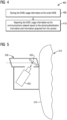
- FIG. 5 illustrates a schematic diagram of an enclosure 500 that is tamper resistant not in accordance with the invention.
- the enclosure 500 is configured to house a camera 505 on a frontal end 510 of a smart EVSE 515 in accordance with one illustrative embodiment of the present invention.
- the enclosure 500 is configured to provide a periscope arrangement using a high-resolution mirror 520 to enable the flexibility of the camera 505 positioning. Since the camera 505 is inaccessible from outside and away from a direct contact, the enclosure 500 acts as an anti-tamper configuration.
Description
- The present disclosure generally relates to electric vehicle charging stations and the invention more specifically relates to a smart Electric Vehicle Supply Equipment, EVSE, charging station.
- Electric vehicle charging stations such as smart electric vehicle charging stations are rapidly growing in popularity. More features are being incorporated into electric vehicle charging stations. For example, there are now messaging enabled electric vehicle charging stations that have built-in-communication modules. Such electric vehicle charging stations allow wireless communications of charging data to a server over a network.
- Conducting monetary transactions through mobile devices is known. Human sale points allow customers to purchase products and services using the customers' financial information. For example, credit card based monetary transactions may be carried out by systems that can either read data from a magnetic strap attached to the card enabling the system to read details of the card for identification or by mechanically inputting the card number and other card details such as the name of the card owner and the expiry date of the card, which are usually printed or engraved on one surface of the card as well as the Card Verification Value Code (CVV or CVC) which is usually printed or engraved in the back surface of the card. However, electric vehicle charging stations cannot be used for conducting or managing such monetary transactions using customers' financial information.
- With a perceived need for increased security and surveillance, many parking lot owners and homeowners have installed alarm systems, including some with passive infrared motion sensors. However, despite the availability of a wide variety of monitoring systems, there is still a need for improvements in this field of technology.
- Typically, user identification for monetary transactions has been addressed through card readers. Tamper deterrence has been addressed through physically securing devices. Physical security and monitoring has been addressed through use of a separate security system. However, multiple functionality gaps exist in electric vehicle charging stations. Some of these gaps involve user identification, tamper deterrence, physical security of a parking lot and home garage security and monitoring.
- In the published patent prior art,
EP 2 514 624 A2 generally describes a method and system for authorizing the charging of an electric vehicle's batteries based on biometric identity information. The system relates the preamble of claim 1. - Therefore, there is generally a need for improvements to user identification, tamper deterrence, physical security of a parking lot and home garage security and monitoring through electric vehicle charging stations.
- The object of the present invention is in particular to provide an EVSE charging station which allows electric vehicle charging stations owners to charge for services in a safe and secure environment without deploying additional equipment. This object is solved by claim 1 and further advantages embodiments and improvements of the invention are listed in the dependent claims. In view of this, the present disclosuregenerally relates to an electric vehicle charging station including built-in-cameras to allow video and pictures taken by the camera to be transmitted to a server or a mobile phone and stored on the electric vehicle charging station and processed locally as camera or image data for performing various camera functions such as authentication, security monitoring, motion detection etc. In particular, authentication information is received at the electric vehicle charging station and compared to acquired camera or image data for user identification or payment authentication. The electric vehicle charging station usage information is stored and communicated based on the authentication information and the acquired camera or image data to a server via a communications network. Electric vehicle charging station usage information includes a specific time when the electric vehicle charging station is used and an amount of energy used at the specific time. In this way, user identification, tamper deterrence, physical security of a parking lot and home garage security and monitoring may be done through an electric vehicle charging station of the present invention by using one or more cameras. One of ordinary skill in the art appreciates that such a camera system can be configured to be integrated in different environments where security, monitoring, identification or authentication is needed, for example, in a parking lot and a home garage installations of the electric vehicle charging station.
- In accordance with the present disclosure, a smart Electric Vehicle Supply Equipment (EVSE) is provided. The smart EVSE comprises a networked on-charging station camera unit disposed either internally to the smart EVSE or connected externally on the smart EVSE. The camera unit may include at least one of a video camera and a still image camera. The smart EVSE may further comprise a communication module coupled to the camera unit, the communication module is configured to: (i) communicate acquired camera data over a camera connection as private communications to a server over a Local Area Network or a mobile device of a user over a cellular network, (ii) communicate the acquired camera data to the server or the mobile device of the user over a public network infrastructure by connecting to Internet or a networked communications system, or (iii) communicate the acquired camera data to the server or the mobile device of the user over a combination of one or more public networks and one or more private networks.
- In accordance with the present disclosure, a smart Electric Vehicle Supply Equipment (EVSE) is provided. According to the present invention, a smart EVSE comprises a body having an exterior surface and a camera unit integrated with the body. The camera unit has a camera disposed on the exterior surface. The camera is communicatively coupled to a server via a communications network. The camera unit includes a processor configured to receive authentication information of a user of the smart EVSE over the communications network and a storage device configured to store the authentication information locally at the smart EVSE and store EVSE usage information. The processor is configured to compare the stored authentication information with information acquired from the camera to ascertain an identity of the user of the smart EVSE.
- In accordance with the present disclosure, a method is provided. The method includes integrating a camera with a body of a smart Electric Vehicle Supply Equipment (EVSE), communicatively coupling the camera to a server via a communications network, acquiring information from the camera, receiving authentication information of a user of the smart EVSE over the communications network, storing the authentication information locally at the smart EVSE and comparing the stored authentication information with the information acquired from the camera to ascertain an identity of the user of the smart EVSE.
-
-
FIG. 1 illustrates a schematic diagram of a smart Electric Vehicle Supply Equipment (EVSE) including a camera unit not in accordance with the present invention. -
FIG. 2 illustrates a perspective view of a smart EVSE with a networked on-charging station camera unit in accordance with one illustrative embodiment of the present invention. -
FIG. 3 illustrates a flow chart of a method of integrating a camera with a body of a smart Electric Vehicle Supply Equipment (EVSE) in accordance with an exemplary embodiment of the present invention. -
FIG. 4 illustrates a flow chart of a method of storing and reporting EVSE usage information in accordance with one illustrative embodiment of the present invention. -
FIG. 5 illustrates a schematic diagram of an enclosure that is tamper resistant and houses a camera not in accordance with the present invention. - To facilitate an understanding of embodiments, principles, and features of the present invention, they are explained hereinafter with reference to implementation in illustrative embodiments. In particular, they are described in the context of providing a camera unit operable to capture, store, transmit video and still images and provide image data for the video and still images for use in user identification, payment authentication, and security monitoring etc. Embodiments of the present invention, however, are not limited to use in the described devices or methods.
- A camera system is provided for an electric vehicle charging station such as a smart Electric Vehicle Supply Equipment (EVSE). The system comprises an enclosure for mounting a camera unit on an exterior surface of a body of the smart EVSE. The camera unit may include a video camera and/or a still image camera. The smart EVSE includes a communication module coupled to the camera unit. The communication module is configured to communicate acquired camera data over a camera connection to a server or a mobile device over a public network, a private network or a combination of both. The smart EVSE includes a processor communicatively coupled to the camera unit. The smart EVSE further includes a media storage device to store the acquired camera data and store EVSE usage information.
- Accordingly, means of integration of a still and/or video camera with a smart EVSE are provided. The camera may be provided internally to the smart EVSE or connected externally. The smart EVSE also provides means of communications of the camera information. A camera connection to a server or a mobile device may enable private communications to a specific point or public infrastructure may be used to connect the camera data to the Internet or other networked communications system.
-
FIG. 1 illustrates a schematic diagram of a smart Electric Vehicle Supply Equipment (EVSE) 10 including a networked on-chargingstation camera unit 12 not in accordance with the present invention. The networked on-chargingstation camera unit 12 may be disposed either internally to thesmart EVSE 10 or connected externally on thesmart EVSE 10. For example, the networked on-chargingstation camera unit 12 may include a built-invideo camera 15 and/or a built-in stillimage camera 17. Thesmart EVSE 10 allows pictures taken by the built-in-cameras to be displayed on a screen and stored on the smart EVSE 10 and wirelessly or otherwise transmitted as digital photos or digital video files. - As used herein, the "camera unit" refers to a camera, as described herein, which corresponds to digital photography and audio, video recording. The "camera unit," in addition to the exemplary hardware description next, refers to a device that is configured to take still pictures, record, stream, store, download and upload videos and audio. The "camera unit," may be capable of operating in multiple modes such as a still camera configuration mode and/or a video camera configuration mode. The "camera unit" may be rated for high reliability operation in the most extreme outdoor environments.
- Examples of the networked on-charging
station camera unit 12 include an IPix 2.2 mega pixel 180° command view dome camera which is compatible with normal light conditions. In yet another embodiment, an AXIS-2420 infra-red camera, an IQI3-603 3.3 mega pixel camera and a BOSCH auto-track camera for motion tracking may be used for low light applications. A person skilled in the pertinent art would appreciate that other suitable cameras may be readily deployed based on a specific implementation. - Examples of the built-in
video camera 15 include a video recorder that may be a high definition (HD) video recorder capable of recording 1080p and/or 720p video at 30 frames per second. The video recorder may alternatively be a standard definition video recorder limited to recording in lower resolutions, such as a video graphics array (VGA) resolution of 640×480. The video recorder may be provided by Premier, Chicony, Ability, Foxlink, IAC, or the like. A person skilled in the pertinent art would appreciate that other suitable video recorders may be readily deployed based on the specific implementation.. - The built-in
video camera 15 may be coupled with other electronic components to provide streaming of image data from a video recorder to a wireless data connection, such as Bluetooth, WiFi, and/or a cellular data connection. For example, the built-invideo camera 15 may be coupled to a graphics processor, a microprocessor, and a communications module. Either video or images may be transmitted from the built-invideo camera 15 to the communications module. - While the networked on-charging
station camera unit 12 is described here as the built-invideo camera 15 and/or the built-in stillimage camera 17, the techniques described herein are not limited to still or video cameras but can be also used with other cameras, such as different types of infra-red, and/or night-vision cameras could be deployed. - The
smart EVSE 10 may further include acommunication module 20 coupled to the networked on-chargingstation camera unit 12. Thecommunication module 20 may be configured to communicate acquired camera orimage data 22 over acamera connection 25 as private communications to aserver 27 over anetwork 30 such as a Local Area Network (LAN) 32 or to amobile device 35 of auser 37 over thenetwork 30 such as acellular network 40. - The
server 27 may be an EVSE server or a server that is specifically configured for payment or security. The acquired camera orimage data 22 may reach theserver 27 by way of public networks, private networks, or a combination of both. The image data, or information derived from the acquired camera orimage data 22 may be (but is not required) made available to the users'mobile device 35 or other computing device over thenetwork 30. Theserver 27 may store and report EVSE usage information associated with the information derived from a local camera such as the built-invideo camera 15 and/or the built-in stillimage camera 17 via thenetwork 30. - Alternatively, the
communication module 20 may be configured to communicate the acquired camera orimage data 22 to theserver 27 or themobile device 35 of theuser 37 over a public network infrastructure by connecting toInternet 42 or a networked communications system (not shown). Alternatively, thecommunication module 20 may be configured to communicate the acquired camera orimage data 22 to theserver 27 or themobile device 35 of theuser 37 over a combination of one or more public networks such as theInternet 42 and one or more private networks such as the LAN 32 or thecellular network 40. - The
smart EVSE 10 may further include aprocessor 47 communicatively coupled to the networked on-chargingstation camera unit 12. The networked on-chargingstation camera unit 12 may be operable to capture, store, transmit video and still images and provide the acquired camera orimage data 22 for the video and still images to theprocessor 47. Theprocessor 47 may process the digital photos or digital video files to detect motion from the acquired camera orimage data 22. - The
processor 47 used may be rated for a minimum of 1 GHz of processor power. Typically, 1 GHz processors are easily able to perform the multiple tasks needed to acquire and store images while performing many other critical functions such as data encryption, storage, replication, and transmission. Theprocessor 47 has the capability to process and archive all alarm/photographic data, and to store the data in secured, removable and non-removable media for redundancy. - In one example of video transmissions, data may be streamed from the networked on-charging
station camera unit 12 at high definition in a 220 Mbps stream with a resolution of 1280×720 to a graphics processor (not shown). The graphics processor may encode and scale the video data into a particular video format, such as an H.264 video stream, and scale the video into a 0.5 Mbps stream with a resolution of 480×360. The encoded and scaled video stream from the graphics processor may be transmitted to theprocessor 47, which packages the data for transmission through thecommunication module 20. - The
communication module 20 transmits the data to theserver 27 through a cellular data connection. According to another embodiment, thecommunication module 20 transmits the data to another device (not shown), which then transmits the data to theserver 27. An audio recorder coupled to theprocessor 47 may be sampled nearly simultaneously with the encoded and scaled video stream by theprocessor 47 and combined to generate an audio and video data stream. - The
smart EVSE 10 may further include anenclosure 45 that is tamper resistant (seeFIG. 5 for details). Theenclosure 45 may be configured to house the built-invideo camera 15 and/or the built-in stillimage camera 17 of the networked on-chargingstation camera unit 12. - A power system for the networked on-charging
station camera unit 12 may be a 12 Volt 5 Amp AC-DC power converter. This power converter may be supplied power via a 120 VAC wall outlet or through a battery/charging system. - The
smart EVSE 10 may further include amedia storage device 50 to store the acquired camera orimage data 22 and store EVSE usage information including a specific time when thesmart EVSE 10 is used and an amount of energy used at the specific time. Themedia storage device 50 may enable an offline operation of thesmart EVSE 10. Themedia storage device 50 may be either a flash memory drive or fixed flash memory media. - For example, 2.5" and 3.5" Flash Memory Drives (FMD's) are currently available with a storage capacity of up to 528 Gbytes. A 528 Gbytes FMD would be capable of storing data at a typical write rate and JPEG picture file size every minute, 24 hours a day, 365 days a year. Alternatively, Solid-State Hard Drives up to 4 Tbytes may be used for bigger needs of storage capacity.
- All data collected from the networked on-charging
station camera unit 12 is stored on themedia storage device 50. The networked on-chargingstation camera unit 12 may be powered from thesmart EVSE 10 through a power supply point on the smart EVSE 10 and transfer all data through a network switch to thesmart EVSE 10. - All data collected from the networked on-charging
station camera unit 12 may be stored encrypted on themedia storage device 50. The encrypted data may be transferred to a local computer via VPN/Firewall that is connected to an uplink port on the network switch. All data transfers into and from the camera system may go through the VPN/Firewall. - In another example, the acquired camera or
image data 22 from the built-invideo camera 15 may be stored in themedia storage device 50. When storing video in themedia storage device 50, a user may be able to select between several options for quality of video recorded in themedia storage device 50. The quality options may include, for example, a selection between high definition and standard definition recording. The standard definition option may store video at a resolution of 480×360. When storing data in standard definition, data may be stored through a similar process described above for streaming standard definition video, except the data is passed from theprocessor 47 to themedia storage device 50. - When storing the acquired camera or
image data 22 in high definition, data may be streamed from the built-invideo camera 15 at high definition in a 220 Mbps stream with a resolution of 1280×720 to a graphics processor (not shown). The graphics processor may encode and scale the video data into a H.264 video stream at a resolution of 1280×720 with a data rate of 8 Mbps. The encoded and scaled video stream from the graphics processor may be transmitted to theprocessor 47, which stores the video stream in themedia storage device 50. - The
processor 47 may transmit the encoded and scaled video stream to thecommunications module 20, where the video stream is transmitted to another device for storage. Although storage and streaming of the video are discussed separately above, the processes may operate simultaneously, such that the video is streamed through thecommunications module 20 and stored in themedia storage device 50 simultaneously. - The video and images may be stored in the
media storage device 50 as AVI, JPEG, MPEG files, or in other suitable file formats by thesmart EVSE 10. Theprocessor 47 may upload the processed video to theserver 27 through a wired or a wireless connection such as a 3G/4G/5G cellular data connection. Alternatively, a high-bandwidth wireless connection, such as WiFi may be established between the smart EVSE 10 and theserver 27. - The
smart EVSE 10 may further include asensor 52 responsive to motion or user activation. Thesensor 52 may be provided internally to thesmart EVSE 10 or installed externally on thesmart EVSE 10. - The
smart EVSE 10 may further include a shortrange communications module 55 for Bluetooth communications, adisplay screen 57 to interactively interact with the user and display a portion of the acquired camera orimage data 22, aspeaker 60 and amicrophone 62 for audio communications and a touch screen orkeyboard interface 65 for providing user interface functions. - The
smart EVSE 10 may further include apayment module 67 that enables theuser 37 to make apayment 70 for EVSE usage to charge an electric vehicle (EV) based on the acquired camera orimage data 22. For example, thepayment 70 may be done in US dollars for the kW/$ energy used by the electric vehicle (EV) for charging it or for a duration of charge time as $/hr. Other ways of payment are also possible. - The
smart EVSE 10 may further include atransaction module 72 coupled to thepayment module 67. Thetransaction module 72 may be configured to conduct monetary transactions through abilling center 75. Thetransaction module 72 enables verifying authorization for executing each transaction at thebilling center 75. - The
billing center 75 may be associated with at least one credit company of credit card of a user. Thebilling center 75 may be associated with one or more credit companies enabling to retrieve data from one or more databases. Thebilling center 75 retrieves data from a database (not shown) to check authorization of a transaction according to predefined authorization rules. - The
payment module 67 may enable to authenticate theuser 37 in each session. The authentication may be carried out by enabling a user to input details through mobile device 35 (e.g., pin code, user name and password etc.), where the input details may be authenticated by thepayment module 67 based on the acquired camera orimage data 22. - The
smart EVSE 10 may use the networked on-chargingstation camera unit 12 as a biometric input device to acquire at least one biometric characteristic of theuser 37 to enable identification of theuser 37, where thepayment module 67 enables authenticating theuser 37 by biometric identification of theuser 37 by searching through a biometric database (not shown) operatively associated with thepayment module 67 to identify the inputted biometric characteristics. - The authentication of the
user 37 may be carried out by, for example, enabling the user to input authentication details (e.g., code) and authenticating those details using a database including names and statuses of authorized users; by using biometric identification; and/or by using the mobile device's 35 ID (e.g., phone number or IP address) to automatically identify theuser 37. - The
smart EVSE 10 may further include animage analysis module 77 to analyze the acquired camera orimage data 22 of theuser 37 for identifying theuser 37 by making a security or an identity determination. An image acquisition unit (not shown) of theimage analysis module 77 may acquire an image of a credit card or a graphic image 79 (e.g., 3D code) on themobile device 35, when the credit card or themobile device 35 is placed in front of the built-invideo camera 15 and/or the built-in stillimage camera 17 of the networked on-chargingstation camera unit 12. - The authentication of the
user 37 may be carried out by checking a received image according to predefined rules and conditions by theimage analysis module 77. Theimage analysis module 77 may analyze the received image (e.g. using OCR analysis technique) to identify the details of the credit card and/or thegraphic image 79. - In the
smart EVSE 10, the built-invideo camera 15 and/or the built-in stillimage camera 17 may be configured to read thegraphic image 79 from themobile device 35 of theuser 37 of thesmart EVSE 10 to make a payment authentication. For example, thegraphic image 79 may be a 3D authentication code with encoded authentication information. A 3D QR code or 3D barcode can be used in some embodiments of the present invention. 3D barcodes may be read by using the differences in height between the bars and spaces. This is different from 1D or 2D barcodes that are read by their contrast. - For additional fraud prevention, 3D secure authentication may be used. The 3D secure authentication stands for 3 Domain Server as there are 3 parties that are involved in the 3D secure process: the company the purchase is being made from, the Acquiring Bank (the bank of the company) and VISA® and MasterCard® (the card issuers themselves). This scheme is a collective of Verified by VISA® (VBV) and MasterCard® Secure Code (MSC). After one enters credit card details, a new window will appear, requesting a personal security code. The financial institution will authenticate the transaction within seconds, as well as confirm that one is the individual who is making the purchase. If one hasn't yet registered with Verified by VISA® or MasterCard® SecureCode, one'll need to activate this feature first. One can do this during the payment process, or activate it in advance through the VISA® or MasterCard® website.
- The
communication module 20 can transmit a still image or a live or previously stored streaming video from the built-invideo camera 15 and/or the built-in stillimage camera 17 to a camera application (APP) 82 installed on themobile device 35 for a security determination, a monitoring function, an identification analysis and/or a payment processing. - In operation, the
communication module 20 may transmit analert signal 80 to thecamera APP 82 of an operator to cause thecamera APP 82 to indicate that motion has been detected. Thealert signal 80 may otherwise be transmitted to another camera application (APP) of a monitoring person, an infrastructure operation system, or a monitoring system. - Likewise, the
communication module 20 may transmit thealert signal 80 to theserver 27 of anoperator 85 to indicate that motion has been detected. Alternatively, thecommunication module 20 may transmit a still image or a live or previously stored streaming video from the built-invideo camera 15 and/or the built-in stillimage camera 17 to theserver 27 for a security determination, a monitoring function, an identification analysis and/or a payment processing. - The smart EVSE according to the invention is equipped with an integrated camera that is connected to a server via a network that can receive authentication information from the network and store that information locally. The smart EVSE has an ability to compare authentication information previously received with information derived from a local camera regardless of the status of the communications network. The smart EVSE has an ability to store and report EVSE usage information via the communication network based on authentication information previously received with information derived from the local camera.
- Referring to
FIG. 2 , it illustrates a perspective view of asmart EVSE 200 with a built-incamera unit 205 in accordance with the present invention. Thesmart EVSE 200 includes ahousing 202 that contains the circuitry of the EVSE charging station. Thehousing 202 may include aholder 204 that supports aconnector 206 when thesmart EVSE 200 is not in use charging an EV. Theconnector 206 may be electrically coupled to thesmart EVSE 200 via a chargingcable 208. The chargingcable 208 enters thehousing 202 at a lower edge of thehousing 202. - The
smart EVSE 200 comprises abody 210 having anexterior surface 215. Thesmart EVSE 200 includes the built-incamera unit 205 integrated with thebody 210. The built-incamera unit 205 has acamera 220 disposed on theexterior surface 215. Thecamera 220 is communicatively coupled to aserver 225 via acommunications network 230. - In accordance with the present invention, the built-in
camera unit 205 includes aprocessor 235 configured to receiveauthentication information 240 of a user of thesmart EVSE 200 over thecommunications network 230. The built-incamera unit 205 further includes astorage device 245 configured to store,camera data 247, theauthentication information 240 locally at thesmart EVSE 200 and storeEVSE usage information 250. Thecamera data 247 may include digital photos or digital video files. TheEVSE usage information 250 includes a specific time when thesmart EVSE 200 is used and an amount of energy used at the specific time. - The
processor 235 is configured to compare the storedauthentication information 240 with information acquired fromcamera 255 to ascertain an identity of the user of thesmart EVSE 200. The information acquired fromcamera 255 may be extracted from thecamera data 247. Examples of the information acquired fromcamera 255 include user identification information, payment authentication information, security monitoring information etc. - The
processor 235 is configured to report theEVSE usage information 250 via thecommunications network 230 based on the storedauthentication information 240 and the information acquired fromcamera 255. - Consistent with one embodiment, the
smart EVSE 200 may further include adisplay screen 260 to interactively interact with the user and display a portion of thecamera data 247, aspeaker 265 and amicrophone 270 for audio communications, atouch screen 275 and akeyboard interface 280 for providing user interface functions. - The
smart EVSE 200 with theintegrated camera 220 may include local storage and/or a communication module. Thus, images and video may be recorded and stored for download to another device later. Additionally, images and video may be streamed from the integrated camera in thesmart EVSE 200 to another location, such as a mobile phone or a server, where the images and video may be processed or stored. - Electronic components, such as a communication module, a video recorder, a processor, a graphics processor, a memory, and a data storage port may be coupled and/or attached to a circuit board of the
smart EVSE 200. According to one embodiment, several of the electronic components may be integrated into a system-on-chip (SoC). For example, the graphics processor, the processor, and the memory may be contained on a single SoC coupled and/or attached to the circuit board. - It should be appreciated that several other components may be included in the
smart EVSE 200. However, the function and use of such equipment for a charging station electronics application are well known in the art and are not discussed further. - The built-in
camera unit 205 may be a camera and a computer combined in one intelligent unit. The built-incamera unit 205 is configured to capture and send stored or live video directly over an Internet Protocol (IP) Network such as a Local Area Network (LAN), intranet or the Internet and enables users to view and/or manage the camera using a standard web-browser or video management software on a local or remote computer on a network. The built-incamera unit 205 allows authorized viewers from different locations to simultaneously access images from the same network camera. - The
smart EVSE 200 may provide common operating system (OS) functions like a desktop computer OS functions. This OS may enable security logging, data storage, data authentication, user troubleshooting, date/time synchronization, data transfer management, and a platform from which a camera system operates. Two operating systems appropriate for use in embodiments of the present invention are Windows® and Linux®. Either of the operating systems can be embedded into thesmart EVSE 200. - By the built-in
camera unit 205, according to one embodiment of the invention, motion may be detected within a field of view of thecamera 220 such as the built-invideo camera 15 and/or the built-in stillimage camera 17. This data is then used to notify a user, or trigger a sequence of events. For example, when motion is sensed, the built-incamera unit 205 is programmed to take a picture of the area under view and have it saved for later viewing. - The built-in
camera unit 205 can also be programmed to transmit streaming video. Preferably, the built-incamera unit 205 is sensitive to infra-red light. - The detection of motion by the built-in
camera unit 205 may be used to cause a snapshot to be taken of the front area of thesmart EVSE 200. In contrast, an embodiment of the present invention uses a combination infrared illuminator and a camera to detect motion in a field of view. - Once the
processor 235 has determined that motion exists, according to one embodiment of the invention, it may then initiate any of the following exemplary procedures: notify a remote server or a mobile device using a radio link, take a snapshot (freeze) picture of the area under view and/or turn on a communication module to display live motion video. - Turning now to
FIG. 3 , it illustrates a flow chart of amethod 300 of integrating thecamera 220 with thebody 210 of the smart Electric Vehicle Supply Equipment (EVSE) 200. Reference is made to the elements and features described inFIGs. 1-2 whereFIG. 1 is not in accordance with the invention andFIG. 2 is in accordance with the invention. It should be appreciated that some steps are not required to be performed in any particular order, and that some steps are optional. - In
step 305, thecamera 220 may be integrated with thebody 210 of the smart Electric Vehicle Supply Equipment (EVSE) 200 as an internally built-in camera or an externally installed on-charging station camera. Thecamera 220 is communicatively coupled to theserver 225 via thecommunications network 230 instep 310. - In
step 315, theprocessor 235 acquire information from thecamera 220. Theprocessor 235 receives theauthentication information 240 of a user of thesmart EVSE 200 over thecommunications network 230 atstep 320. Theprocessor 235 stores theauthentication information 240 locally at thesmart EVSE 200 in thestorage device 245 atstep 325. Instep 330, theprocessor 235 reads thegraphic image 79 from themobile device 35 of theuser 37 of thesmart EVSE 200 to make a payment authentication. Alternatively, the graphic image is affixed on a vehicle of the user. For example, a graphic image may be affixed on a license tag plate of the vehicle. - For instance, a payment may be either prearranged or a payment interface may be on the users'
mobile device 35. The payment authentication may be made by theuser 37 holding his mobile device 35 (with a 3D code) in front of thesmart EVSE 200 and a camera of thesmart EVSE 200 would read the 3D code. - In
step 335, theprocessor 235 compares the storedauthentication information 240 with the information acquired fromcamera 255 to ascertain an identity of the user of thesmart EVSE 200. Based on the user identity determination, a payment authentication may be done for a service of providing charge by thesmart EVSE 200 to an electric vehicle of a user at a parking lot or a public charging station. - The
mobile device 35 may include one or more software applications for performing the method described inFIG. 3 . For example, when themobile device 35 is a cellular phone, an application may be available for the cellular phone to control the networked on-chargingstation camera unit 12 ofFIG. 1 . The application may include an interface for selecting a video quality of the built-invideo camera 15 and/or the built-in stillimage camera 17, selecting a server for uploading video from the built-invideo camera 15 and/or the built-in stillimage camera 17, activating and deactivating the built-invideo camera 15 and/or the built-in stillimage camera 17, programming a scheduled time for activating and deactivating the built-invideo camera 15 and/or the built-in stillimage camera 17, selecting options for processing video received from the built-invideo camera 15 and/or the built-in stillimage camera 17, selecting options for processing of the video by electronic components in the networked on-chargingstation camera unit 12 before transferring the video to themobile device 35, and/or a selecting streaming or local storage mode for the networked on-chargingstation camera unit 12. Alternatively, these described functionalities can be performed via theserver 27. -
FIG. 4 illustrates a flow chart of amethod 400 of storing and reporting the EVSE usage information 250Reference is made to the elements and features described inFIGs. 1-2 whereFIG. 1 is not in accordance with the invention andFIG. 2 is in accordance with the invention. It should be appreciated that some steps are not required to be performed in any particular order, and that some steps are optional. - The
method 400 includes storing theEVSE usage information 250 including a specific time when the smart EVSE is used and an amount of energy used at the specific time in thestorage device 245 for use by theprocessor 235 atstep 405. Instep 410, theEVSE usage information 250 is reported by theprocessor 235 to theserver 225 via thecommunications network 230 based on the storedauthentication information 240 and the information acquired fromcamera 255. -
FIG. 5 illustrates a schematic diagram of anenclosure 500 that is tamper resistant not in accordance with the invention. Theenclosure 500 is configured to house acamera 505 on afrontal end 510 of asmart EVSE 515 in accordance with one illustrative embodiment of the present invention. Theenclosure 500 is configured to provide a periscope arrangement using a high-resolution mirror 520 to enable the flexibility of thecamera 505 positioning. Since thecamera 505 is inaccessible from outside and away from a direct contact, theenclosure 500 acts as an anti-tamper configuration. - Embodiments of the present invention can be integrated into currently deployed electric vehicle charging stations, allowing for operators to retrofit electric vehicle charging stations with a camera. Embodiments of the present invention will allow electric vehicle charging stations owners to charge for services in a safe and secure environment without deploying additional equipment. With known installation methods, the embodiments of the present invention may provide a retrofit solution, requiring no removal of installed electric vehicle charging stations. Embodiments of the present invention may increase the overall safety and functionality of operations of electric vehicle charging stations.
- Embodiments of the present invention can be integrated into currently deployed electric vehicle charging stations, allowing for operators to retrofit electric vehicle charging stations with a camera. Embodiments of the present invention will allow electric vehicle charging stations owners to charge for services in a safe and secure environment without deploying additional equipment. With known installation methods, the embodiments of the present invention may provide a retrofit solution, requiring no removal of installed electric vehicle charging stations. Embodiments of the present invention may increase the overall safety and functionality of operations of electric vehicle charging stations.
- While embodiments of the present invention have been disclosed in exemplary forms, it will be apparent to those skilled in the art that many modifications, additions, and deletions can be made therein without departing from the spirit and scope of the invention and its equivalents, as set forth in the following claims.
- Embodiments and the various features and advantageous details thereof are explained more fully with reference to the non-limiting embodiments that are illustrated in the accompanying drawings and detailed in the following description. Descriptions of well-known starting materials, processing techniques, components and equipment are omitted so as not to unnecessarily obscure embodiments in detail. It should be understood, however, that the detailed description and the specific examples, while indicating preferred embodiments, are given by way of illustration only and not by way of limitation. Various substitutions, modifications, additions and/or rearrangements within the spirit and/or scope of the underlying inventive concept will become apparent to those skilled in the art from this disclosure.
- As used herein, the terms "comprises," "comprising," "includes," "including," "has," "having" or any other variation thereof, are intended to cover a non-exclusive inclusion. For example, a process, article, or apparatus that comprises a list of elements is not necessarily limited to only those elements but may include other elements not expressly listed or inherent to such process, article, or apparatus.
- Additionally, any examples or illustrations given herein are not to be regarded in any way as restrictions on, limits to, or express definitions of, any term or terms with which they are utilized. Instead, these examples or illustrations are to be regarded as being described with respect to one particular embodiment and as illustrative only. Those of ordinary skill in the art will appreciate that any term or terms with which these examples or illustrations are utilized will encompass other embodiments which may or may not be given therewith or elsewhere in the specification and all such embodiments are intended to be included within the scope of that term or terms.
- In the foregoing specification, the invention has been described with reference to specific embodiments. However, one of ordinary skill in the art appreciates that various modifications and changes can be made without departing from the scope of the invention. Accordingly, the specification and figures are to be regarded in an illustrative rather than a restrictive sense, and all such modifications are intended to be included within the scope of invention.
- Although the invention has been described with respect to specific embodiments thereof, these embodiments are merely illustrative, and not restrictive of the invention. The description herein of illustrated embodiments of the invention is not intended to be exhaustive or to limit the invention to the precise forms disclosed herein (and in particular, the inclusion of any particular embodiment, feature or function is not intended to limit the scope of the invention to such embodiment, feature or function). Rather, the description is intended to describe illustrative embodiments, features and functions in order to provide a person of ordinary skill in the art context to understand the invention without limiting the invention to any particularly described embodiment, feature or function. While specific embodiments of, and examples for, the invention are described herein for illustrative purposes only, various equivalent modifications are possible within the spirit and scope of the invention, as those skilled in the relevant art will recognize and appreciate. As indicated, these modifications may be made to the invention in light of the foregoing description of illustrated embodiments of the invention and are to be included within the spirit and scope of the invention. Thus, while the invention has been described herein with reference to particular embodiments thereof, a latitude of modification, various changes and substitutions are intended in the foregoing disclosures, and it will be appreciated that in some instances some features of embodiments of the invention will be employed without a corresponding use of other features without departing from the scope and spirit of the invention as set forth. Therefore, many modifications may be made to adapt a particular situation or material to the essential scope and spirit of the invention.
- Respective appearances of the phrases "in one embodiment," "in an embodiment," or "in a specific embodiment" or similar terminology in various places throughout this specification are not necessarily referring to the same embodiment. Furthermore, the particular features, structures, or characteristics of any particular embodiment may be combined in any suitable manner with one or more other embodiments. It is to be understood that other variations and modifications of the embodiments described and illustrated herein are possible in light of the teachings herein and are to be considered as part of the spirit and scope of the invention.
- In the description herein, numerous specific details are provided, such as examples of components and/or methods, to provide a thorough understanding of embodiments of the invention. One skilled in the relevant art will recognize, however, that an embodiment may be able to be practiced without one or more of the specific details, or with other apparatus, systems, assemblies, methods, components, materials, parts, and/or the like. In other instances, well-known structures, components, systems, materials, or operations are not specifically shown or described in detail to avoid obscuring aspects of embodiments of the invention. While the invention may be illustrated by using a particular embodiment, this is not and does not limit the invention to any particular embodiment and a person of ordinary skill in the art will recognize that additional embodiments are readily understandable and are a part of this invention.
- Although the steps, operations, or computations may be presented in a specific order, this order may be changed in different embodiments. In some embodiments, to the extent multiple steps are shown as sequential in this specification, some combination of such steps in alternative embodiments may be performed at the same time.
- Embodiments described herein can be implemented in the form of control logic in software or hardware or a combination of both. The control logic may be stored in an information storage medium, such as a computer-readable medium, as a plurality of instructions adapted to direct an information processing device to perform a set of steps disclosed in the various embodiments. Based on the disclosure and teachings provided herein, a person of ordinary skill in the art will appreciate other ways and/or methods to implement the invention.
- It will also be appreciated that one or more of the elements depicted in the drawings/figures can also be implemented in a more separated or integrated manner as is useful in accordance with a particular application.
- Benefits, other advantages, and solutions to problems have been described above with regard to specific embodiments. However, the benefits, advantages, solutions to problems, and any component(s) that may cause any benefit, advantage, or solution to occur or become more pronounced are not to be construed as a critical, required, or essential feature or component.
Claims (7)
- A smart Electric Vehicle Supply Equipment, EVSE, (200) charging station, the smart EVSE (200) charging station comprising:a) a housing (202) that contains circuitry of the EVSE charging station;b) a body (210) having an exterior surface (215); andc) a camera unit (205) integrated with the body (210), the camera unit (205) having a camera (220) disposed on the exterior surface (215), wherein the camera (220) is communicatively coupled to a server (225) via a communications network (230), and wherein the camera (220) is configured to read a graphic image from a mobile device (35) of a user (37) of the smart EVSE (200) charging station or a graphic image affixed on a vehicle of the user to make a payment authentication,characterized in that the camera unit (205) includes:c1) a processor (235) configured to receive (320) authentication information (240) of a user of the smart EVSE (200) charging station over the communications network (230), andc2) a storage device (245) configured to store (325) the authentication information (240) locally at the smart EVSE (200) charging station and store EVSE usage information (250),c3) wherein the processor (235) is configured to compare (335) the stored authentication information (240) with information acquired from the camera (255) to ascertain an identity of the user of the smart EVSE (200) charging station; whereinc4) the processor (235) is further configured to report the EVSE usage information (250) via the communications network (230) to the server (225), wherein the EVSE usage information (250) includes a specific time when the smart EVSE (200) charging station is used and an amount of energy used at the specific time.
- The smart EVSE (200) charging station of claim 1, wherein the graphic image is a 3D authentication code.
- The smart EVSE, (200) charging station of claim 1, wherein the camera unit (204):a) includes at least one of a video camera (15) and a still image camera (17); andb) is configured to capture and send stored or live video directly over an Internet Protocol (IP) network such as a Local Area Network (LAN), intranet or the Internet.
- The smart EVSE (200) charging station of claim 1, the a housing (202) including a holder (204) configured to support a connector (206) when the smart EVSE (200) charging station is not in use charging an electric vehicle, the connector (206) electrically coupled to the smart EVSE (200) charging station via a charging cable (208).
- The smart EVSE (200) charging station of claim 1, wherein the processor (235) of the camera unit (205) is adapted to detect motion within a field of view of the camera (220).
- The smart EVSE (200) charging station of claim 5, wherein once the processor (235) has determined that motion exists, it then initiates any of the following procedures: notify a remote server or a mobile device using a radio link, take a snapshot picture of the area under view and/or turn on a communication module to display live motion video.
- The smart EVSE (200) charging station of claim 1, further comprising:a display screen (260) to interactively interact with the user and display a portion of the acquired camera data ;a speaker (265) and a microphone (270) for audio communications; anda touch screen (275) and keyboard interface (280) for providing user interface functions.
Applications Claiming Priority (1)
| Application Number | Priority Date | Filing Date | Title |
|---|---|---|---|
| US15/045,994 US10021354B2 (en) | 2016-02-17 | 2016-02-17 | Electric vehicle charging station with integrated camera |
Publications (4)
| Publication Number | Publication Date |
|---|---|
| EP3208137A2 EP3208137A2 (en) | 2017-08-23 |
| EP3208137A3 EP3208137A3 (en) | 2017-09-27 |
| EP3208137B1 true EP3208137B1 (en) | 2023-08-16 |
| EP3208137C0 EP3208137C0 (en) | 2023-08-16 |
Family
ID=57906422
Family Applications (1)
| Application Number | Title | Priority Date | Filing Date |
|---|---|---|---|
| EP17151808.7A Active EP3208137B1 (en) | 2016-02-17 | 2017-01-17 | Electric vehicle charging station with integrated camera |
Country Status (4)
| Country | Link |
|---|---|
| US (2) | US10021354B2 (en) |
| EP (1) | EP3208137B1 (en) |
| CN (1) | CN107089157B (en) |
| ES (1) | ES2955605T3 (en) |
Families Citing this family (45)
| Publication number | Priority date | Publication date | Assignee | Title |
|---|---|---|---|---|
| JP6294903B2 (en) * | 2016-03-22 | 2018-03-14 | 株式会社Subaru | vehicle |
| HK1217604A2 (en) * | 2016-05-18 | 2017-01-13 | 香港生產力促進局 | Automatic electric ground service equipment parking bay monitoring system |
| US11568703B2 (en) * | 2016-06-08 | 2023-01-31 | Sichuan Energy Internet Res. Inst., Tsinghua Univ. | Systems and methods for wireless charging stations |
| KR20190046063A (en) * | 2017-10-25 | 2019-05-07 | 현대자동차주식회사 | User authentication system, User authentication method And Server |
| US10303045B1 (en) | 2017-12-20 | 2019-05-28 | Micron Technology, Inc. | Control of display device for autonomous vehicle |
| US10877999B2 (en) | 2017-12-21 | 2020-12-29 | Micron Technology, Inc. | Programmatically identifying a personality of an autonomous vehicle |
| CN107972520A (en) * | 2017-12-25 | 2018-05-01 | 芜湖雪影实业有限公司 | A kind of charging station |
| TWI741245B (en) * | 2017-12-29 | 2021-10-01 | 英屬開曼群島商睿能創意公司 | Systems and methods for managing energy storage devices positioned in device exchange station |
| US10894545B2 (en) * | 2018-03-14 | 2021-01-19 | Micron Technology, Inc. | Configuration of a vehicle based on collected user data |
| US11148658B2 (en) | 2018-03-21 | 2021-10-19 | Micron Technology, Inc. | Personalization of a vehicle based on user settings |
| JP7091798B2 (en) * | 2018-04-13 | 2022-06-28 | トヨタ自動車株式会社 | Vehicle charging system and vehicle charging system certification method |
| CN108597117A (en) * | 2018-04-24 | 2018-09-28 | 上海上汽安悦充电科技有限公司 | A kind of operation system of charging pile |
| CN108608882B (en) * | 2018-05-07 | 2020-09-25 | 江苏卓燃工程咨询有限公司 | Electric energy automobile with automatic protection function during charging |
| CN109050307A (en) * | 2018-08-14 | 2018-12-21 | 苏州中充科技发展有限公司 | Vehicular charging management system and its charging method |
| CN109228919A (en) * | 2018-08-24 | 2019-01-18 | 高福程 | A kind of electric automobile charging pile for protecting cable |
| CN110015064A (en) * | 2018-10-29 | 2019-07-16 | 深圳市诺微科技有限公司 | Security protection charging system |
| DE102018126939A1 (en) * | 2018-10-29 | 2020-04-30 | Innogy Se | Charging unit for electric vehicles |
| US11496472B2 (en) * | 2018-11-16 | 2022-11-08 | Mutualink, Inc. | System and method for secure access to camera systems |
| US11951864B2 (en) | 2018-11-20 | 2024-04-09 | Volvo Car Corporation | Charging station monitoring system |
| CN111196174A (en) | 2018-11-20 | 2020-05-26 | 沃尔沃汽车公司 | Charging station monitoring system |
| US11336662B2 (en) * | 2018-11-21 | 2022-05-17 | Abb Schweiz Ag | Technologies for detecting abnormal activities in an electric vehicle charging station |
| CN109291827A (en) * | 2018-12-03 | 2019-02-01 | 上海上汽安悦充电科技有限公司 | A kind of information of charging pile display system and method |
| US10657343B1 (en) * | 2018-12-10 | 2020-05-19 | Paypal, Inc. | Location-based embedded patterns for vehicle detection and data processing |
| US11173797B2 (en) * | 2018-12-30 | 2021-11-16 | Berk-Tek Llc | Vehicle charging station with built-in wireless access point, computing and storage |
| CN109714369B (en) * | 2019-02-28 | 2021-08-13 | 深圳智链物联科技有限公司 | Communication method of distributed charging pile communication system, charging pile and networking device |
| CN110077913A (en) * | 2019-04-17 | 2019-08-02 | 安徽科创新能源科技有限责任公司 | A kind of charging pile protective device |
| EP3969322A4 (en) | 2019-05-13 | 2023-02-01 | Volta Charging, LLC | Charging station with articulating panels |
| CN111942207A (en) * | 2020-08-14 | 2020-11-17 | 高丰 | Electric automobile intelligent charging management system based on big data |
| CN112078419A (en) * | 2020-08-24 | 2020-12-15 | 奇瑞新能源汽车股份有限公司 | Electric vehicle charging system and charging control method thereof |
| CN112224068B (en) * | 2020-08-26 | 2022-06-14 | 南方电网电动汽车服务有限公司 | Photovoltaic power generation energy storage charging system |
| US11518258B2 (en) * | 2020-10-21 | 2022-12-06 | Rivian Ip Holdings, Llc | Holster sensor for electric vehicle charging system |
| CN112140937B (en) * | 2020-10-23 | 2022-03-29 | 深圳百跑科技有限公司 | Double-gun combined charging method and system for charging pile |
| CN112519614A (en) * | 2020-12-11 | 2021-03-19 | 王雨萌 | Electric automobile charging scheme |
| US11413977B2 (en) * | 2020-12-11 | 2022-08-16 | Dovene Komi Deh | Charging assembly for electric vehicle |
| CN112801715B (en) * | 2021-02-20 | 2023-12-12 | 北京九泉科技有限公司 | Intelligent control system of water purifier |
| USD1009780S1 (en) * | 2021-06-17 | 2024-01-02 | Canoo Technologies Inc. | Charger |
| US20230084015A1 (en) | 2021-09-13 | 2023-03-16 | Iotecha Corp. | Devices for home based electric vehicle (ev) charging |
| CN113859013A (en) * | 2021-10-27 | 2021-12-31 | 安徽中科智充新能源科技有限公司 | Fill electric pile safety record appearance and mounting structure thereof |
| JP2023067455A (en) * | 2021-11-01 | 2023-05-16 | トヨタ自動車株式会社 | Power supply system, control device and power supply system control method |
| USD999725S1 (en) * | 2021-11-15 | 2023-09-26 | Canoo Technologies Inc. | Charging device |
| USD1001063S1 (en) * | 2021-11-15 | 2023-10-10 | Canoo Technologies Inc. | Charging device |
| CN114013324B (en) * | 2022-01-05 | 2022-04-15 | 成都国星宇航科技有限公司 | Charging device with built-in multifunctional camera and charging monitoring method |
| USD1001729S1 (en) * | 2022-04-29 | 2023-10-17 | Gongniu Group Co., Ltd. | Charging station for electric vehicles |
| CN114872574B (en) * | 2022-07-01 | 2022-09-23 | 惠州市丝鹭新能源科技有限公司 | Acquisition and monitoring system and method based on charging pile |
| USD999161S1 (en) * | 2022-07-07 | 2023-09-19 | Aiswei New Energy Technology (yangzhong) Co., Ltd. | Electric vehicle charger |
Citations (5)
| Publication number | Priority date | Publication date | Assignee | Title |
|---|---|---|---|---|
| JP2007070999A (en) * | 2005-09-05 | 2007-03-22 | Takahiro Suzuki | System for unlocking and locking key by issuing qr code from cellular phone |
| US20110131083A1 (en) * | 2009-12-01 | 2011-06-02 | Liberty Pluglns, Inc. | Method and apparatus for parking lot management |
| US20110213656A1 (en) * | 2010-02-23 | 2011-09-01 | Optimization Technologies, Inc. | Electric vehicle charging station parking meter systems |
| EP2514624A2 (en) * | 2011-04-20 | 2012-10-24 | General Electric Company | Method and system for authorizing the charging of an electric vehicle's batteries based on biometric identity information |
| EP2738735A1 (en) * | 2011-07-26 | 2014-06-04 | Mitsubishi Heavy Industries, Ltd. | Charge infrastructure management system, control method, and program |
Family Cites Families (17)
| Publication number | Priority date | Publication date | Assignee | Title |
|---|---|---|---|---|
| US20090177580A1 (en) * | 2008-01-07 | 2009-07-09 | Lowenthal Richard W | Collection of electric vehicle power consumption tax |
| JP2011166283A (en) * | 2010-02-05 | 2011-08-25 | Enegate:Kk | Power feeding system for electric automobile |
| ES2346283B1 (en) | 2010-03-03 | 2011-09-05 | Miguel Salamanques Claver | CONTROL SYSTEM AND MANAGEMENT OF ENERGY RECHARGE, COMMUNICATION AND LIGHTING. |
| US20140067660A1 (en) | 2011-03-11 | 2014-03-06 | Kevin Terrill Cornish | Method and process for an electric vehicle charging system to automatically engage the charging apparatus of an electric vehicle |
| CN202043250U (en) * | 2011-05-26 | 2011-11-16 | 山东鲁能智能技术有限公司 | Video surveillance system of electric vehicle charging and switching station |
| US9304566B2 (en) * | 2011-10-31 | 2016-04-05 | General Electric Company | Systems and methods for use in communicating with a charging station |
| US9352652B2 (en) | 2012-06-29 | 2016-05-31 | Schneider Electric USA, Inc. | Coupler for electric vehicle charging station |
| US20140067493A1 (en) * | 2012-08-29 | 2014-03-06 | Optimization Technologies, Inc. | System for combining payment for electric vehicle charging and parking |
| DE102013206587A1 (en) * | 2013-04-12 | 2014-10-16 | Siemens Aktiengesellschaft | System for controlling the charging process of an electric and / or hybrid vehicle |
| US9440549B2 (en) * | 2013-05-03 | 2016-09-13 | Semmaconnect Inc. | System and method for detecting vehicle proximity in an electrical vehicle supply equipment |
| US10384642B2 (en) * | 2013-07-17 | 2019-08-20 | Conduent Business Services, Llc | Methods and systems for vehicle theft detection and prevention using a smartphone and video-based parking technology |
| US20150032617A1 (en) * | 2013-07-23 | 2015-01-29 | Amadeus Sas | Secure Channel Payment Processing System and Method |
| CN203658809U (en) | 2013-12-10 | 2014-06-18 | 国网上海市电力公司 | Electric vehicle charging station |
| US11091046B2 (en) | 2014-02-07 | 2021-08-17 | Recargo, Inc. | System for providing an interface to electric vehicle charging stations |
| US20160019492A1 (en) * | 2014-07-18 | 2016-01-21 | EV Connect, Inc. | Charge station queue management |
| CN204361717U (en) * | 2014-12-23 | 2015-05-27 | 洪振宇 | A kind of electric automobile Intelligent charging spot |
| US10181227B2 (en) * | 2015-12-31 | 2019-01-15 | Bosch Automotive Service Solutions Inc. | Self service vehicle diagnostics |
-
2016
- 2016-02-17 US US15/045,994 patent/US10021354B2/en active Active
-
2017
- 2017-01-17 ES ES17151808T patent/ES2955605T3/en active Active
- 2017-01-17 EP EP17151808.7A patent/EP3208137B1/en active Active
- 2017-02-17 CN CN201710086105.7A patent/CN107089157B/en active Active
-
2018
- 2018-04-30 US US15/966,705 patent/US10425621B2/en active Active
Patent Citations (5)
| Publication number | Priority date | Publication date | Assignee | Title |
|---|---|---|---|---|
| JP2007070999A (en) * | 2005-09-05 | 2007-03-22 | Takahiro Suzuki | System for unlocking and locking key by issuing qr code from cellular phone |
| US20110131083A1 (en) * | 2009-12-01 | 2011-06-02 | Liberty Pluglns, Inc. | Method and apparatus for parking lot management |
| US20110213656A1 (en) * | 2010-02-23 | 2011-09-01 | Optimization Technologies, Inc. | Electric vehicle charging station parking meter systems |
| EP2514624A2 (en) * | 2011-04-20 | 2012-10-24 | General Electric Company | Method and system for authorizing the charging of an electric vehicle's batteries based on biometric identity information |
| EP2738735A1 (en) * | 2011-07-26 | 2014-06-04 | Mitsubishi Heavy Industries, Ltd. | Charge infrastructure management system, control method, and program |
Non-Patent Citations (1)
| Title |
|---|
| GE INDUSTRIAL SOLUTION: "WattStation(TM) Wall Mount - User Manual", 1 June 2015 (2015-06-01), XP055694415, Retrieved from the Internet <URL:http://apps.geindustrial.com/publibrary/checkout/DEA-534?TNR=Installation%20and%20Instruction]DEA-534]PDF&filename=DEA-534.pdf> [retrieved on 20200512] * |
Also Published As
| Publication number | Publication date |
|---|---|
| ES2955605T3 (en) | 2023-12-04 |
| CN107089157B (en) | 2021-01-05 |
| US10021354B2 (en) | 2018-07-10 |
| EP3208137A2 (en) | 2017-08-23 |
| CN107089157A (en) | 2017-08-25 |
| US20170237944A1 (en) | 2017-08-17 |
| EP3208137A3 (en) | 2017-09-27 |
| US20180249129A1 (en) | 2018-08-30 |
| EP3208137C0 (en) | 2023-08-16 |
| US10425621B2 (en) | 2019-09-24 |
Similar Documents
| Publication | Publication Date | Title |
|---|---|---|
| US10425621B2 (en) | Electric vehicle charging station with integrated camera | |
| US11605051B2 (en) | System for parcel transport and tracking operated responsive to data bearing records | |
| US20150248595A1 (en) | Apparatus and method for automatic license plate recognition and traffic surveillance | |
| US11676464B2 (en) | Body mounted camera system for monitoring deliveries | |
| US11375840B2 (en) | System for parcel transport and tracking operated responsive to data bearing records | |
| US11429924B2 (en) | System for parcel transport and tracking operated responsive to data bearing records | |
| Rao et al. | Surveillance camera using IOT and Raspberry Pi | |
| CN105654618A (en) | Automatic vender and automatic vending system | |
| CN106529812A (en) | Intelligent archives management system and application | |
| US11568696B2 (en) | System operated responsive to data bearing records | |
| US11748697B2 (en) | System for parcel pickup and delivery operated responsive to data bearing records | |
| CA3065993C (en) | System operated responsive to data bearing records | |
| US9165173B2 (en) | Security method using an imaging barcode reader | |
| KR20210070745A (en) | Pos video search system | |
| CA3105762C (en) | System for parcel transport and tracking operated responsive to data bearing records | |
| JP4957396B2 (en) | Surveillance camera system and method thereof | |
| TWI547176B (en) | Monitoring system with ultra-wide-angle camera and method for transmitting monitoring signals | |
| TWI612499B (en) | Site management method and site management system | |
| CA3118229A1 (en) | System operated responsive to data bearing records | |
| CA3119682A1 (en) | System for parcel pickup and delivery operated responsive to data bearing records | |
| CA3110989A1 (en) | System for parcel transport and tracking operated responsive to data bearing records | |
| CA3153163A1 (en) | System for parcel transport operated responsive to data bearing records | |
| CA3105765A1 (en) | System for parcel transport and tracking operated responsive to data bearing records | |
| TW201201149A (en) | Access security system with video surveillance and method for the same |
Legal Events
| Date | Code | Title | Description |
|---|---|---|---|
| PUAI | Public reference made under article 153(3) epc to a published international application that has entered the european phase |
Free format text: ORIGINAL CODE: 0009012 |
|
| STAA | Information on the status of an ep patent application or granted ep patent |
Free format text: STATUS: THE APPLICATION HAS BEEN PUBLISHED |
|
| AK | Designated contracting states |
Kind code of ref document: A2 Designated state(s): AL AT BE BG CH CY CZ DE DK EE ES FI FR GB GR HR HU IE IS IT LI LT LU LV MC MK MT NL NO PL PT RO RS SE SI SK SM TR |
|
| AX | Request for extension of the european patent |
Extension state: BA ME |
|
| PUAL | Search report despatched |
Free format text: ORIGINAL CODE: 0009013 |
|
| AK | Designated contracting states |
Kind code of ref document: A3 Designated state(s): AL AT BE BG CH CY CZ DE DK EE ES FI FR GB GR HR HU IE IS IT LI LT LU LV MC MK MT NL NO PL PT RO RS SE SI SK SM TR |
|
| AX | Request for extension of the european patent |
Extension state: BA ME |
|
| RIC1 | Information provided on ipc code assigned before grant |
Ipc: H04N 7/18 20060101ALI20170824BHEP Ipc: G06K 9/00 20060101ALI20170824BHEP Ipc: H04N 5/225 20060101ALI20170824BHEP Ipc: B60L 11/18 20060101AFI20170824BHEP Ipc: H04N 5/77 20060101ALI20170824BHEP Ipc: G06Q 20/14 20120101ALI20170824BHEP |
|
| STAA | Information on the status of an ep patent application or granted ep patent |
Free format text: STATUS: REQUEST FOR EXAMINATION WAS MADE |
|
| 17P | Request for examination filed |
Effective date: 20180327 |
|
| RBV | Designated contracting states (corrected) |
Designated state(s): AL AT BE BG CH CY CZ DE DK EE ES FI FR GB GR HR HU IE IS IT LI LT LU LV MC MK MT NL NO PL PT RO RS SE SI SK SM TR |
|
| STAA | Information on the status of an ep patent application or granted ep patent |
Free format text: STATUS: EXAMINATION IS IN PROGRESS |
|
| 17Q | First examination report despatched |
Effective date: 20190417 |
|
| STAA | Information on the status of an ep patent application or granted ep patent |
Free format text: STATUS: EXAMINATION IS IN PROGRESS |
|
| STAA | Information on the status of an ep patent application or granted ep patent |
Free format text: STATUS: EXAMINATION IS IN PROGRESS |
|
| REG | Reference to a national code |
Ref document number: 602017072705 Country of ref document: DE Ref country code: DE Ref legal event code: R079 Free format text: PREVIOUS MAIN CLASS: B60L0011180000 Ipc: G06Q0020140000 |
|
| RIC1 | Information provided on ipc code assigned before grant |
Ipc: B60L 53/14 20190101ALI20230220BHEP Ipc: B60L 53/30 20190101ALI20230220BHEP Ipc: B60L 53/66 20190101ALI20230220BHEP Ipc: B60L 53/65 20190101ALI20230220BHEP Ipc: B60L 53/31 20190101ALI20230220BHEP Ipc: G07F 15/00 20060101ALI20230220BHEP Ipc: G06Q 20/14 20120101AFI20230220BHEP |
|
| GRAP | Despatch of communication of intention to grant a patent |
Free format text: ORIGINAL CODE: EPIDOSNIGR1 |
|
| STAA | Information on the status of an ep patent application or granted ep patent |
Free format text: STATUS: GRANT OF PATENT IS INTENDED |
|
| INTG | Intention to grant announced |
Effective date: 20230404 |
|
| GRAS | Grant fee paid |
Free format text: ORIGINAL CODE: EPIDOSNIGR3 |
|
| GRAA | (expected) grant |
Free format text: ORIGINAL CODE: 0009210 |
|
| STAA | Information on the status of an ep patent application or granted ep patent |
Free format text: STATUS: THE PATENT HAS BEEN GRANTED |
|
| AK | Designated contracting states |
Kind code of ref document: B1 Designated state(s): AL AT BE BG CH CY CZ DE DK EE ES FI FR GB GR HR HU IE IS IT LI LT LU LV MC MK MT NL NO PL PT RO RS SE SI SK SM TR |
|
| REG | Reference to a national code |
Ref country code: GB Ref legal event code: FG4D |
|
| REG | Reference to a national code |
Ref country code: CH Ref legal event code: EP Ref country code: DE Ref legal event code: R096 Ref document number: 602017072705 Country of ref document: DE |
|
| REG | Reference to a national code |
Ref country code: IE Ref legal event code: FG4D |
|
| U01 | Request for unitary effect filed |
Effective date: 20230817 |
|
| U07 | Unitary effect registered |
Designated state(s): AT BE BG DE DK EE FI FR IT LT LU LV MT NL PT SE SI Effective date: 20230823 |
|
| REG | Reference to a national code |
Ref country code: ES Ref legal event code: FG2A Ref document number: 2955605 Country of ref document: ES Kind code of ref document: T3 Effective date: 20231204 |
|
| REG | Reference to a national code |
Ref country code: NO Ref legal event code: T2 Effective date: 20230816 |
|
| PG25 | Lapsed in a contracting state [announced via postgrant information from national office to epo] |
Ref country code: GR Free format text: LAPSE BECAUSE OF FAILURE TO SUBMIT A TRANSLATION OF THE DESCRIPTION OR TO PAY THE FEE WITHIN THE PRESCRIBED TIME-LIMIT Effective date: 20231117 |
|
| PG25 | Lapsed in a contracting state [announced via postgrant information from national office to epo] |
Ref country code: IS Free format text: LAPSE BECAUSE OF FAILURE TO SUBMIT A TRANSLATION OF THE DESCRIPTION OR TO PAY THE FEE WITHIN THE PRESCRIBED TIME-LIMIT Effective date: 20231216 |
|
| PG25 | Lapsed in a contracting state [announced via postgrant information from national office to epo] |
Ref country code: RS Free format text: LAPSE BECAUSE OF FAILURE TO SUBMIT A TRANSLATION OF THE DESCRIPTION OR TO PAY THE FEE WITHIN THE PRESCRIBED TIME-LIMIT Effective date: 20230816 Ref country code: IS Free format text: LAPSE BECAUSE OF FAILURE TO SUBMIT A TRANSLATION OF THE DESCRIPTION OR TO PAY THE FEE WITHIN THE PRESCRIBED TIME-LIMIT Effective date: 20231216 Ref country code: HR Free format text: LAPSE BECAUSE OF FAILURE TO SUBMIT A TRANSLATION OF THE DESCRIPTION OR TO PAY THE FEE WITHIN THE PRESCRIBED TIME-LIMIT Effective date: 20230816 Ref country code: GR Free format text: LAPSE BECAUSE OF FAILURE TO SUBMIT A TRANSLATION OF THE DESCRIPTION OR TO PAY THE FEE WITHIN THE PRESCRIBED TIME-LIMIT Effective date: 20231117 |
|
| U20 | Renewal fee paid [unitary effect] |
Year of fee payment: 8 Effective date: 20240119 |
|
| PG25 | Lapsed in a contracting state [announced via postgrant information from national office to epo] |
Ref country code: PL Free format text: LAPSE BECAUSE OF FAILURE TO SUBMIT A TRANSLATION OF THE DESCRIPTION OR TO PAY THE FEE WITHIN THE PRESCRIBED TIME-LIMIT Effective date: 20230816 |