EP3208111A1 - Tire - Google Patents
Tire Download PDFInfo
- Publication number
- EP3208111A1 EP3208111A1 EP17150043.2A EP17150043A EP3208111A1 EP 3208111 A1 EP3208111 A1 EP 3208111A1 EP 17150043 A EP17150043 A EP 17150043A EP 3208111 A1 EP3208111 A1 EP 3208111A1
- Authority
- EP
- European Patent Office
- Prior art keywords
- shoulder
- main groove
- center
- tire
- groove
- Prior art date
- Legal status (The legal status is an assumption and is not a legal conclusion. Google has not performed a legal analysis and makes no representation as to the accuracy of the status listed.)
- Granted
Links
Images



Classifications
-
- B—PERFORMING OPERATIONS; TRANSPORTING
- B60—VEHICLES IN GENERAL
- B60C—VEHICLE TYRES; TYRE INFLATION; TYRE CHANGING; CONNECTING VALVES TO INFLATABLE ELASTIC BODIES IN GENERAL; DEVICES OR ARRANGEMENTS RELATED TO TYRES
- B60C11/00—Tyre tread bands; Tread patterns; Anti-skid inserts
- B60C11/03—Tread patterns
- B60C11/0306—Patterns comprising block rows or discontinuous ribs
- B60C11/0309—Patterns comprising block rows or discontinuous ribs further characterised by the groove cross-section
-
- B—PERFORMING OPERATIONS; TRANSPORTING
- B60—VEHICLES IN GENERAL
- B60C—VEHICLE TYRES; TYRE INFLATION; TYRE CHANGING; CONNECTING VALVES TO INFLATABLE ELASTIC BODIES IN GENERAL; DEVICES OR ARRANGEMENTS RELATED TO TYRES
- B60C11/00—Tyre tread bands; Tread patterns; Anti-skid inserts
- B60C11/03—Tread patterns
- B60C11/0306—Patterns comprising block rows or discontinuous ribs
-
- B—PERFORMING OPERATIONS; TRANSPORTING
- B60—VEHICLES IN GENERAL
- B60C—VEHICLE TYRES; TYRE INFLATION; TYRE CHANGING; CONNECTING VALVES TO INFLATABLE ELASTIC BODIES IN GENERAL; DEVICES OR ARRANGEMENTS RELATED TO TYRES
- B60C11/00—Tyre tread bands; Tread patterns; Anti-skid inserts
- B60C11/03—Tread patterns
- B60C11/0304—Asymmetric patterns
-
- B—PERFORMING OPERATIONS; TRANSPORTING
- B60—VEHICLES IN GENERAL
- B60C—VEHICLE TYRES; TYRE INFLATION; TYRE CHANGING; CONNECTING VALVES TO INFLATABLE ELASTIC BODIES IN GENERAL; DEVICES OR ARRANGEMENTS RELATED TO TYRES
- B60C11/00—Tyre tread bands; Tread patterns; Anti-skid inserts
- B60C11/03—Tread patterns
- B60C11/0311—Patterns comprising tread lugs arranged parallel or oblique to the axis of rotation
-
- B—PERFORMING OPERATIONS; TRANSPORTING
- B60—VEHICLES IN GENERAL
- B60C—VEHICLE TYRES; TYRE INFLATION; TYRE CHANGING; CONNECTING VALVES TO INFLATABLE ELASTIC BODIES IN GENERAL; DEVICES OR ARRANGEMENTS RELATED TO TYRES
- B60C11/00—Tyre tread bands; Tread patterns; Anti-skid inserts
- B60C11/03—Tread patterns
- B60C11/12—Tread patterns characterised by the use of narrow slits or incisions, e.g. sipes
-
- B—PERFORMING OPERATIONS; TRANSPORTING
- B60—VEHICLES IN GENERAL
- B60C—VEHICLE TYRES; TYRE INFLATION; TYRE CHANGING; CONNECTING VALVES TO INFLATABLE ELASTIC BODIES IN GENERAL; DEVICES OR ARRANGEMENTS RELATED TO TYRES
- B60C11/00—Tyre tread bands; Tread patterns; Anti-skid inserts
- B60C11/03—Tread patterns
- B60C11/12—Tread patterns characterised by the use of narrow slits or incisions, e.g. sipes
- B60C11/1236—Tread patterns characterised by the use of narrow slits or incisions, e.g. sipes with special arrangements in the tread pattern
-
- B—PERFORMING OPERATIONS; TRANSPORTING
- B60—VEHICLES IN GENERAL
- B60C—VEHICLE TYRES; TYRE INFLATION; TYRE CHANGING; CONNECTING VALVES TO INFLATABLE ELASTIC BODIES IN GENERAL; DEVICES OR ARRANGEMENTS RELATED TO TYRES
- B60C11/00—Tyre tread bands; Tread patterns; Anti-skid inserts
- B60C11/03—Tread patterns
- B60C11/13—Tread patterns characterised by the groove cross-section, e.g. for buttressing or preventing stone-trapping
-
- B—PERFORMING OPERATIONS; TRANSPORTING
- B60—VEHICLES IN GENERAL
- B60C—VEHICLE TYRES; TYRE INFLATION; TYRE CHANGING; CONNECTING VALVES TO INFLATABLE ELASTIC BODIES IN GENERAL; DEVICES OR ARRANGEMENTS RELATED TO TYRES
- B60C11/00—Tyre tread bands; Tread patterns; Anti-skid inserts
- B60C11/03—Tread patterns
- B60C11/13—Tread patterns characterised by the groove cross-section, e.g. for buttressing or preventing stone-trapping
- B60C11/1307—Tread patterns characterised by the groove cross-section, e.g. for buttressing or preventing stone-trapping with special features of the groove walls
-
- B—PERFORMING OPERATIONS; TRANSPORTING
- B60—VEHICLES IN GENERAL
- B60C—VEHICLE TYRES; TYRE INFLATION; TYRE CHANGING; CONNECTING VALVES TO INFLATABLE ELASTIC BODIES IN GENERAL; DEVICES OR ARRANGEMENTS RELATED TO TYRES
- B60C11/00—Tyre tread bands; Tread patterns; Anti-skid inserts
- B60C11/03—Tread patterns
- B60C11/13—Tread patterns characterised by the groove cross-section, e.g. for buttressing or preventing stone-trapping
- B60C11/1376—Three dimensional block surfaces departing from the enveloping tread contour
- B60C11/1392—Three dimensional block surfaces departing from the enveloping tread contour with chamfered block edges
-
- B—PERFORMING OPERATIONS; TRANSPORTING
- B60—VEHICLES IN GENERAL
- B60C—VEHICLE TYRES; TYRE INFLATION; TYRE CHANGING; CONNECTING VALVES TO INFLATABLE ELASTIC BODIES IN GENERAL; DEVICES OR ARRANGEMENTS RELATED TO TYRES
- B60C11/00—Tyre tread bands; Tread patterns; Anti-skid inserts
- B60C11/03—Tread patterns
- B60C2011/0337—Tread patterns characterised by particular design features of the pattern
- B60C2011/0339—Grooves
- B60C2011/0341—Circumferential grooves
-
- B—PERFORMING OPERATIONS; TRANSPORTING
- B60—VEHICLES IN GENERAL
- B60C—VEHICLE TYRES; TYRE INFLATION; TYRE CHANGING; CONNECTING VALVES TO INFLATABLE ELASTIC BODIES IN GENERAL; DEVICES OR ARRANGEMENTS RELATED TO TYRES
- B60C11/00—Tyre tread bands; Tread patterns; Anti-skid inserts
- B60C11/03—Tread patterns
- B60C2011/0337—Tread patterns characterised by particular design features of the pattern
- B60C2011/0339—Grooves
- B60C2011/0341—Circumferential grooves
- B60C2011/0353—Circumferential grooves characterised by width
-
- B—PERFORMING OPERATIONS; TRANSPORTING
- B60—VEHICLES IN GENERAL
- B60C—VEHICLE TYRES; TYRE INFLATION; TYRE CHANGING; CONNECTING VALVES TO INFLATABLE ELASTIC BODIES IN GENERAL; DEVICES OR ARRANGEMENTS RELATED TO TYRES
- B60C11/00—Tyre tread bands; Tread patterns; Anti-skid inserts
- B60C11/03—Tread patterns
- B60C2011/0337—Tread patterns characterised by particular design features of the pattern
- B60C2011/0339—Grooves
- B60C2011/0358—Lateral grooves, i.e. having an angle of 45 to 90 degees to the equatorial plane
-
- B—PERFORMING OPERATIONS; TRANSPORTING
- B60—VEHICLES IN GENERAL
- B60C—VEHICLE TYRES; TYRE INFLATION; TYRE CHANGING; CONNECTING VALVES TO INFLATABLE ELASTIC BODIES IN GENERAL; DEVICES OR ARRANGEMENTS RELATED TO TYRES
- B60C11/00—Tyre tread bands; Tread patterns; Anti-skid inserts
- B60C11/03—Tread patterns
- B60C2011/0337—Tread patterns characterised by particular design features of the pattern
- B60C2011/0339—Grooves
- B60C2011/0358—Lateral grooves, i.e. having an angle of 45 to 90 degees to the equatorial plane
- B60C2011/0365—Lateral grooves, i.e. having an angle of 45 to 90 degees to the equatorial plane characterised by width
-
- B—PERFORMING OPERATIONS; TRANSPORTING
- B60—VEHICLES IN GENERAL
- B60C—VEHICLE TYRES; TYRE INFLATION; TYRE CHANGING; CONNECTING VALVES TO INFLATABLE ELASTIC BODIES IN GENERAL; DEVICES OR ARRANGEMENTS RELATED TO TYRES
- B60C11/00—Tyre tread bands; Tread patterns; Anti-skid inserts
- B60C11/03—Tread patterns
- B60C2011/0337—Tread patterns characterised by particular design features of the pattern
- B60C2011/0386—Continuous ribs
-
- B—PERFORMING OPERATIONS; TRANSPORTING
- B60—VEHICLES IN GENERAL
- B60C—VEHICLE TYRES; TYRE INFLATION; TYRE CHANGING; CONNECTING VALVES TO INFLATABLE ELASTIC BODIES IN GENERAL; DEVICES OR ARRANGEMENTS RELATED TO TYRES
- B60C11/00—Tyre tread bands; Tread patterns; Anti-skid inserts
- B60C11/03—Tread patterns
- B60C2011/0337—Tread patterns characterised by particular design features of the pattern
- B60C2011/0386—Continuous ribs
- B60C2011/0388—Continuous ribs provided at the equatorial plane
-
- B—PERFORMING OPERATIONS; TRANSPORTING
- B60—VEHICLES IN GENERAL
- B60C—VEHICLE TYRES; TYRE INFLATION; TYRE CHANGING; CONNECTING VALVES TO INFLATABLE ELASTIC BODIES IN GENERAL; DEVICES OR ARRANGEMENTS RELATED TO TYRES
- B60C11/00—Tyre tread bands; Tread patterns; Anti-skid inserts
- B60C11/03—Tread patterns
- B60C11/13—Tread patterns characterised by the groove cross-section, e.g. for buttressing or preventing stone-trapping
- B60C11/1307—Tread patterns characterised by the groove cross-section, e.g. for buttressing or preventing stone-trapping with special features of the groove walls
- B60C2011/133—Tread patterns characterised by the groove cross-section, e.g. for buttressing or preventing stone-trapping with special features of the groove walls comprising recesses
Definitions
- the present invention relates to a tire with improved on-snow performance.
- Patent Literature 1 discloses a pneumatic tire, wherein the tread portion is provided with a land region defined between main grooves extending continuously in the tire circumferential direction, and the land region is provided with rug grooves extending from one of the main grooves and terminating within the land region, and transverse grooves extending across the entire width of the land region. Further, the corner of the land region formed between the ground contacting surface of the land region and a groove side wall of the main groove is provided with chamfer portions. Both ends in the tire circumferential direction of the chamfer portion are connected to the adjacent rug groove and the adjacent transverse groove, respectively.
- Each of the chamfer portions disclosed in the Patent Literature 1 has its both ends connected to the rug groove and the transverse groove, therefore it is unable to increase the axial component of the edges. Further, in the Patent Literature 1, the land region is not provided with additional chamfer portions at opposite positions to the chamfer portions. Thus, the chamfer portions disclosed in the Patent Literature 1 cannot increase the edge effect sufficiently, and accordingly, it is difficult to improve the on-snow performance.
- the present invention was made in view of the above, and a primary object thereof is to provide a pneumatic tire capable of improving the on-snow performance.
- a tire comprises a tread portion having a first half-tread portion located on one side of the tire equator in the tire axial direction and a second half-tread portion on the other side of the tire equator in the tire axial direction, the first half-tread portion provided with a first shoulder main groove extending continuously in the tire circumferential direction on its most tread-edge side, a first shoulder land region formed axially outside the first shoulder main groove, and a first middle land region formed axially inside the first shoulder main groove, wherein the first shoulder land region is circumferentially divided into first shoulder blocks by first shoulder transverse grooves extending from the first shoulder main groove to the adjacent tread edge, each of the first shoulder blocks has a first shoulder chamfer portion at a corner between a ground contacting surface of the first shoulder block and a groove side wall of the first shoulder main groove, both ends in the tire circumferential direction of the first shoulder chamfer portion terminate without being connected to the adjacent first shoulder transverse grooves, the first middle land region is provided
- tire according the present invention may have the following features (1)-(6):
- the first half-tread portion located one side of the tire equator in the tire axial direction is provided with the first shoulder main groove extending continuously in the tire circumferential direction on its most tread-edge side, the first shoulder land region disposed axially outside the first shoulder main groove, and the first middle land region disposed axially inside the first shoulder main groove.
- the first main groove configured as such compresses the snow into the groove and shears the compresses the snow, therefore, it is possible to improve on-snow performance.
- the first shoulder land region is divided into the first shoulder blocks by the first shoulder transverse grooves extending from the first shoulder main groove to the tread edge.
- the first shoulder transverse grooves configured as such compress the snow into the grooves and shear the compressed snow, therefore, it is possible to improve the on-snow performance.
- the first shoulder blocks each have the first shoulder chamfer portion at the corner between the ground contacting surface of the first shoulder block and the groove side wall of the first shoulder main groove.
- the first chamfer portion configured as such can increase the circumferential edge component, therefore, it is possible to improve the on-snow performance.
- the both ends in the tire circumferential direction of the first shoulder chamfer potion terminate without being connected to the first shoulder transverse grooves.
- an step surface extending in the tire axial direction is formed in the first shoulder transverse groove.
- Such step surface provides an axial edge component and can scratch the snow in the tire circumferential direction, therefore, it is possible to improve the on-snow performance.
- the first middle land region is provided with the first middle rug grooves extending axially inwardly from the first shoulder main groove and terminating within the first middle land region, and the first middle chamfer portions each formed at the corner between the ground contacting surface of the first middle land region and the groove side wall of the first shoulder main groove in a part of the range between a pair of the first middle rug grooves adjacent in the tire circumferential direction.
- the first middle rug groove compresses the snow into the groove and shears it, therefore, it is possible to improve the on-snow performance.
- the first middle chamfer portion can increase the circumferential edge component and can improve the on-snow performance.
- the first middle chamfer portion is formed in a part of the range between a pair of the first middle rug grooves, a step surface extending in the tire axial direction is formed.
- Such step surface provides an axial edge component and can scratch the snow in the tire circumferential direction, therefore, it is possible to improve the on-snow performance.
- the first middle chamfer portions are disposed so as to face the first shoulder chamfer portions. Thereby, the first middle chamfer portions and the first shoulder chamfer portions contact with the ground at the same time, therefore it is possible to greatly increase the edge components and scratch the snow efficiently.
- the tire according to the present invention can improve the on-snow performance.
- the normally inflated unloaded condition is such that the tire is mounted on a standard wheel rim and inflated to a standard pressure but loaded with no tire load.
- the undermentioned normally inflated loaded condition is such that the tire is mounted on the standard wheel rim and inflated to the standard pressure and loaded with the standard tire load.
- the standard wheel rim is a wheel rim officially approved or recommended for the tire by standards organizations, i.e. JATMA (Japan and Asia), T&RA (North America), ETRTO (Europe), TRAA (Australia), STRO (Scandinavia), ALAPA (Latin America), ITTAC (India) and the like which are effective in the area where the tire is manufactured, sold or used.
- the standard pressure and the standard tire load are the maximum air pressure and the maximum tire load for the tire specified by the same organization in the Air-pressure/Maximum-load Table or similar list.
- the standard wheel rim is the "standard rim” specified in JATMA, the "Measuring Rim” in ETRTO, the "Design Rim” in TRA or the like.
- the standard pressure is the “maximum air pressure” in JATMA, the “Inflation Pressure” in ETRTO, the maximum pressure given in the “Tire Load Limits at Various Cold Inflation Pressures” table in TRA or the like.
- the standard load is the "maximum load capacity" in JATMA, the “Load Capacity” in ETRTO, the maximum value given in the above-mentioned table in TRA or the like. In case of passenger car tires, however, the standard pressure and standard tire load are uniformly defined by 180 kPa and 88 % of the maximum tire load, respectively.
- tread edges are the axial outermost edges of the ground contacting patch which occurs under the normally inflated loaded condition when the camber angle of the tire is zero.
- the tread width TW is the width measured under the normally inflated unloaded condition, as the axial distance between the tread edges determined as above.
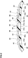
- Fig. 1 shows the tread portion 2 of a passenger car radial tire as an embodiment of the present invention.
- the tread portion 2 in this embodiment has a left-right asymmetric tread pattern for which a mounting position on a vehicle is specified.
- the mounting position is indicated in a sidewall portion and the like of the tire 1 by characters ("INSIDE” and/or "OUTSIDE", for example) and so on (not shown in the figures).
- the tread portion 2 has a first half-tread portion 2A located on one side of the tire equator C in the tire axial direction, and a second half-tread portion 2B located on the other side of the tire equator in the tire axial direction.
- first half-tread portion 2A is located toward the inside Si of the vehicle
- second half-tread portion 2B is located toward the outside So of the vehicle.
- the first half-tread portion 2A is provided with a first shoulder main groove 3C extending continuously in the tire circumferential direction on its most tread-edge 2At side (hereafter, also referred to as "first tread edge"), a first shoulder land region 4D disposed axially outside the first shoulder main groove 3C, and a first middle land region 4B disposed axially inside the first shoulder main groove 3C.
- first half-tread portion 2A in this embodiment is provided with a first center main groove 3A extending continuously in the tire circumferential direction between the tire equator C and the first shoulder main groove 3C.
- first middle land region 4B is defined as being between the first shoulder main groove 3C and the first center main groove 3A.
- the second half-tread portion 2B is provided with a second shoulder main groove 3D extending continuously in the tire circumferential direction on its most tread-edge 2Bt side (hereafter, also referred to as "second tread edge"), a second shoulder land region 4E disposed axially outside the second shoulder main groove 3D, and a second middle land region 4C disposed axially inside the second shoulder main groove 3D.
- the second half-tread portion 2B in this embodiment is provided with a second center main groove 3B extending continuously in the tire circumferential direction between the tire equator C and the second shoulder main groove 3D.
- the second middle land region 4C is defined as being between the second shoulder main groove 3D and the second center main groove 3B.
- the tread portion 2 is provided with a center land region 4A axially divided by the first center main groove 3A and the second center main groove 3B.
- the center land region 4A is provided with a center sub groove 5A extending continuously in the tire circumferential direction on the tire equator C.
- the center land region 4A is composed of a first center land subsection 4Aa defined between the center sub groove 5A and the first center main groove 3A, and a second center land subsection 4Ab defined between the center sub groove 5A and the second center main groove 3B.
- the first center land subsection 4Aa is located in the first half-tread portion 2A
- the second center land subsection 4Ab is located in the second half-tread portion 2B.
- the circumferential length of the ground contacting patch of a pneumatic tire under the normally-inflated normally-loaded state decreases from the tire equator toward the tread edges, and accordingly, the ground contact tends to decrease toward the axially outsides.
- a maximum axial width Wa of the center land region 4A, a maximum axial width Wb of the first middle land region 4B, a maximum axial width Wc of the second middle land region 4C, a maximum axial width Wd of the first shoulder land region 4D, and a maximum axial width We of the second shoulder land region 4E are formed to satisfy the following relationship: Wa ⁇ Wb ⁇ Wc ⁇ Wd ⁇ We .
- the tire in this embodiment can substantially equalize the ground contacting areas of the respective land regions 4A, 4B, 4C, 4D and 4E, and thus can improve the ground contact with the road surface, therefore, it is possible to improve the running performance on dry roads.
- the maximum axial width Wb of the first middle land region 4B and the maximum axial width Wc of the second middle land region 4C are 120% to 130% of the maximum axial width Wa of the center land region 4A.
- the maximum axial width Wd of the first shoulder land region 4D, and the maximum axial width We of the second shoulder land region 4E are 130% to 150 % of the maximum axial width Wa of the center land region 4A.
- the first shoulder main groove 3C and the second shoulder main groove 3D are formed as straight grooves extending straight along the tire circumferential direction.
- the first shoulder main groove 3C and the second shoulder main groove 3D configured as such compress the snow thereinto to form snow blocks, and shear the snow blocks to obtain larger shearing force. Thereby, it is possible to improve the on-snow performance.
- first shoulder main groove 3C and the second shoulder main groove 3D can guide the water film on the road surface toward the tire circumferential direction, therefore, it is possible to improve the wet performance.
- the groove width W1c of the first shoulder main groove 3C and the groove width W1d of the second shoulder main groove 3D are set to be approximately 3% to 8% of the tread width TW.
- the groove depth D1c (shown in Fig. 2 ) of the first shoulder main groove 3C and the groove depth D1d (shown in Fig. 2 ) of the second shoulder main groove 3D are set to be approximately 3% to 7% of the tread width TW.
- the first center main groove 3A and the second center main groove 3B are formed as straight grooves extending straight along the tire circumferential direction in the same way as the first shoulder main groove 3C and the second shoulder main groove 3D.
- the first center main groove 3A and the second center main groove 3B configured as such can improve the on-snow performance and the wet performance in the same way as the first shoulder main groove 3C and the second shoulder main groove 3D.
- the groove width W1a of the first center main groove 3A and the groove width W1b of the second center main groove 3B are set to be in the same range as for the groove width W1c of the first shoulder main groove 3C and the groove width W1d of the second shoulder main groove 3D, namely, approximately 3% to 8% of the tread width TW.
- the groove depth D1a of the first center main groove 3A and the groove depth D1b of the second center main groove 3B are set to be in the same range as for the groove depth D1c of the first shoulder main groove 3C and the groove depth D1d of the second shoulder main groove 3D, namely, approximately 3% to 7% of the tread width TW.
- the center sub groove 5A is formed as a straight groove extending straight along the tire circumferential direction.
- the center sub groove 5A configured as such can improve the on-snow performance and the wet performance in the same way as each of the main grooves 3A, 3B, 3C, and 3D.
- the groove width W1e of the center sub groove 5A is smaller than the groove width W1a of the first center main groove 3A. Further, as shown in Fig. 2 , the groove depth D1e of the center sub groove 5A is smaller than the groove depth D1a of the first center main groove 3A.
- the center sub groove 5A configured as such can prevent the decrease in the rigidity of the first center land subsection 4Aa, therefore, it is possible to maintain the running performance on dry roads.
- the groove width W1e of the center sub groove 5A is set in a range from 0.5% to 1.0% of the tread width TW as shown in Fig. 1 . Further, it is preferred that the groove depth D1e (shown in FIG. 2 ) of the center sub groove 5A is set in a range from 1% to 2 % of the tread width TW.
- the first shoulder land region 4D is provided with the first shoulder transverse grooves 6D extending from the first shoulder main groove 3C to the first tread edge 2At. Thereby, the first shoulder land region 4D is circumferentially divided into the first shoulder blocks 7D.
- the first shoulder transverse grooves 6D configured as such compress the snow thereinto to form snow blocks, and shear the snow blocks to obtain larger shearing force. Thereby, it is possible to improve the snow performance.
- first shoulder transverse grooves 6D can guide the water film on the road surface toward the first shoulder main groove 3C and the first tread edge 2At. Therefore, it is possible to improve the wet performance.
- the first shoulder transverse grooves 6D are inclined with respect to the tire axial direction.
- the edges of the first shoulder transverse grooves 6D configured as such can provide a circumferential component and an axial component in a good balance to improve the on-snow performance.
- the angle ⁇ 2d of the first shoulder transverse groove 6D with respect to the tire circumferential direction is gradually increased from the first shoulder main groove 3C toward the first tread edge 2At in order to drain the water film on the road surface smoothly.
- the groove width W2d of the first shoulder transverse groove 6D is set in a range from 2% to 5% of the tread width TW. Further, as shown in Fig. 2 , it is preferable that the maximum groove depth D2d of the first shoulder transverse groove 6D is set to be approximately 2.5% to 4.5% of the tread width TW. Furthermore, it is preferable that the angle ⁇ 2d is set in a range from 70 to 90 degrees, for example.
- the first shoulder blocks 7D are each configured so that the maximum length Ld thereof in the tire circumferential direction is substantially the same as the maximum width Wd thereof in the tire axial direction, and formed as a parallelogram in the plan view.
- the first shoulder block 7D configured as such can be increased in its rigidity in the tire circumferential direction and the tire axial direction in a good balance, therefore, it is possible to improve the running performance on snowy roads and dry roads.
- the maximum length Ld and the maximum width Wd of the first shoulder block 7D are approximately 15 to 20 % of the tread width TW.
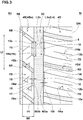
- Fig. 3 shows the first shoulder land region 4D and the first middle land region 4B.
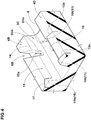
- Fig. 4 shows a first shoulder chamfer portion 10 and a first middle chamfer portion 15.
- Each of the first shoulder blocks 7D is provided with a first shoulder chamfer portion 10 at the corner 8 between the ground contacting surface of the first shoulder block 7D and a groove side wall of the first shoulder main groove 3C.
- the first shoulder chamfer portion 10 has a slope face as shown in Figs. 3 and 4 .
- the first shoulder chamfer portion 10 configured as such can increase the circumferential component of the edges of the first shoulder block 7D to improve the on-snow performance. Further, the first shoulder chamfer portion 10 can partially decrease the ground contacting area of the first shoulder block 7D, therefore, it is possible to improve the wet performance.
- Both ends 10t in the tire circumferential direction of the first shoulder chamfer portion 10 terminate without being connected to the first shoulder transverse grooves 6D, and step surfaces 11 extending in the tire axial direction are formed at the ends 10t.
- the step surfaces 11 can provide an axial edge component to scratch the snow in the tire circumferential direction, therefore, it is possible to improve the on-snow performance.
- step surfaces 11 in this embodiment are formed in the form of a triangle which is tapered toward the inside in the tire radial direction. Thereby, it is possible to suppress the decrease in the rigidity of the first shoulder block 7D, and to maintain the running performance on dry roads.
- the width W3a of the first shoulder chamfer portion 10 is preferably not less than 0.8 mm, more preferably not less than 1.0 mm, and preferably not greater than 2.5 mm, more preferably not greater than 2.0 mm.
- a depth D3a (shown in Fig. 4 ) of the first shoulder chamfer portion 10 is preferably not less than 30 %, more preferably not less than 40 %, and preferably not greater than 60 %, more preferably not greater than 50 % of the groove depth D1a (shown in Fig. 2 ) of the first shoulder main groove 3C.
- the length L3a (shown in Fig. 3 ) in the tire circumferential direction of the first shoulder chamfer portion 10 is preferably not less than 40 %, more preferably not less than 45 %, and preferably not greater than 80 %, more preferably not greater than 60% of the maximum length Ld (shown in Fig. 1 ) of the first shoulder block 7D.
- the first shoulder block 7D is, as shown in Fig. 3 , provided with a pair of first shoulder sipes 12a which respectively extend axially outwardly from the both ends 10t of the first shoulder chamfer portion 10.
- a pair of the first shoulder sipes 12a can increase the edges of the first shoulder block 7D, therefore, it is possible to improve the on-ice performance.
- a pair of the first shoulder sipes 12a co-operates with the step surfaces 11 formed at the both ends 10t of the first shoulder chamfer portion 10 to provide the edges with an axial component, therefore, it is possible to improve the on-snow performance and the on-ice performance.
- the first shoulder sipes 12a are each formed as an open sipe whose both ends are opened at the end 10t of the first shoulder chamfer portion 10 and the first tread edge 2At. Thereby, the edges of the first shoulder sipes 12a are provided over a wide range in the tire axial direction of the first shoulder block 7D, therefore, it is possible to improve the on-ice performance.
- the first shoulder sipes 12a are inclined with respect to the tire axial direction.
- the angle ⁇ 4a of the first shoulder sipe with respect to the tire circumferential direction is substantially in the same range as for the angle ⁇ 2d of the first shoulder transverse grooves 6D.
- the first shoulder sipes 12a configured as such can increase the circumferential component and axial component of the edges of the first shoulder block 7D, therefore, it is possible to improve the on-ice performance.
- each of the first shoulder sipes 12a is preferably set in a range from 0.6 to 1.0 mm. Further, the depth of each of the first shoulder sipes 12a is preferably set in a range from 2.0 to 3.0 mm.
- each of the first shoulder blocks 7D is provided between the first shoulder sipes 12a with a first center shoulder sipe 12b extending in the tire axial direction.
- the first center shoulder sipe 12b configured as such can provide edges in a central portion in the tire circumferential direction of the first shoulder block 7D, therefore, it is possible to improve the on-ice performance.
- the first center shoulder sipe 12b is a semi-open sipe extending axially inwardly from the first tread edge 2At and terminating without reaching the first shoulder chamfer portion 10 and the first shoulder main groove 3C. Thereby, the first center shoulder sipe 12b can suppress the decrease in the rigidity of the first shoulder block 7D to maintain the running performance on dry roads.
- first center shoulder sipe 12b is inclined with respect to the tire axial direction.
- the angle ⁇ 4b of the first center shoulder sipe 12b with respect to the tire circumferential direction is in the same range as for the angle ⁇ 2d of the first shoulder transverse groove 6D and the angle ⁇ 4a of the first shoulder sipe 12a.
- the first center shoulder sipe configured as such can provide the first shoulder block 7D with a circumferential edge component and an axial edge component, therefore, it is possible to improve the on-ice performance.
- the width of the first center shoulder sipe 12b is set in the same range as for the width of the first shoulder sipe 12a. It is preferable that the depth of the first center shoulder sipe 12b is set in the same range as for the depth of the first shoulder sipe 12a.
- the first shoulder block 7D can be provided with a large amount of the edges in comparison with the other land regions and blocks. Further, when the tire 1 in this embodiment is mounted on a vehicle with a negative camber, the first shoulder blocks 7D located toward the inside Si of the vehicle are relatively increased in the ground contact pressure. Therefore, the first shoulder sipes 12a and the first center shoulder sipe 12b can scratch the ice effectively. Thus, it is possible to effectively improve the on-ice performance.
- the first middle land region 4B is provided in the widthwise center thereof with a first middle sub groove 5B extending continuously in the tire circumferential direction.
- the first middle land region 4B is composed of an axially outer first middle land subsection 4Ba defined between the first middle sub groove 5B and the first shoulder main groove 3C, and an axially inner first middle land subsection 4Bb defined between the first middle sub groove 5B and the first center main groove 3A.
- the first middle sub groove is formed as a straight groove extending straight along the tire circumferential direction.
- the first middle sub groove configured as such can improve the on-snow performance and the wet performance in the same way as the main grooves 3A, 3B, 3C and 3D.
- the groove width W1f of the first middle sub groove 5B is smaller than the groove width W1a of the first center main groove 3A. Further as shown in Fig. 2 , the groove depth D1f (shown in Fig. 2 ) of the first middle sub groove 5B is smaller than the groove depth D1a of the first center main groove 3A.
- the first middle sub groove 5B configured as such can suppress the decrease in the rigidity of the first middle land region 4B, therefore, it is possible to maintain the running performance on dry roads.
- the groove width W1f of the first middle sub groove 5B is set in a range from 1.5% to 2.5% of the tread width TW. Further, it is preferable that the groove depth D1f (shown in Fig. 2 ) of the first middle sub groove 5B is set in a range from 1.5% to 3.0% of the tread width TW.
- the first middle land region 4B is provided with first middle rug grooves 6B extending axially inwardly from the first shoulder main groove 3C and terminating within the first middle land region 4B.
- the first middle rug groove 6B extends from the first shoulder main groove 3C to the first middle sub groove 5B.
- the axially outer first middle land subsection 4Ba is circumferentially divided into axially outer first middle blocks 7B.
- the first middle rug groove 6B configured as such can improve the on-snow performance and the wet performance in the same way as the first shoulder transverse groove 6D.
- the first middle rug groove 6B terminates within the first middle land region 4B, therefore, it is possible to suppress the decrease in the rigidity of the first middle land region 4B and to improve the running performance on dry roads.
- a groove width W2b (shown in Fig. 1 ) of the first middle rug groove 6B is set to be approximately 1.5% to 4% of the tread width TW for example. Further, it is preferable that the groove depth D2b (shown in Fig. 2 ) of the first middle rug groove 6B is set to be approximately 2.0% to 4.0% of the tread width TW (shown in Fig. 1 ) for example,
- the first middle rug groove 6B extends with an inclination with respect to the tire circumferential direction.
- the first middle rug groove 6B configured as such can provide both axial edge component and circumferential edge component in a good balance, therefore it is possible to improve the on-snow performance.
- an angle ⁇ 2b of the first middle rug groove 6B with respect to the tire circumferential direction is set to be 45 to 65 degrees.
- the above-mentioned axially outer first middle blocks 7B are each formed as a parallelogram in the plan view with its maximum length Lf in the tire circumferential direction is larger than its maximum width wf in the tire axial direction.
- the axially outer first middle block 7B configured as such can relatively increase the block rigidity, therefore, it is possible to improve the running performance on snowy roads and dry roads.
- the maximum length Lf is set in a range from 15% to 25% of the tread width TW
- the maximum width wf is set in a range from 5% to 10% of the tread width TW.
- the first middle land region 4B (in this embodiment, each of the axially outer first middle blocks 7B) is provided with the first middle chamfer portion 15 at the corner 14 between the ground contacting surface of the first middle land region 4B and the groove side wall of the first shoulder main groove 3C in a part of the range between the first middle rug grooves 6B adjacent in the tire circumferential direction.
- the first middle chamfer portion 15 has a slope face as shown in Fig. 4 .
- the first middle chamfer portion 15 configured as such can increase the circumferential edge component in the first middle land region 4B, therefore, it is possible to improve the on-snow performance. Further, the first middle chamfer portion 15 can partially decrease the ground contacting area of the first middle land region 4B, therefore, it is possible to improve the wet performance.
- the first middle chamfer portion 15 is formed in a part of the range between the first middle rug grooves 6B, therefore, a step surface 16 extending in the tire axial direction is formed.
- one end 15a in the tire circumferential direction of the first middle chamfer portion 15 is connected to the first middle rug groove 6B located on the side of the above-mentioned one end 15a.
- the other end 15b in the tire circumferential direction of the first middle chamfer portion 15 terminates without reaching the first middle rug groove 6B located on the side of the other end 15b. Therefore, the step surface 16 in this embodiment is formed on the other end 15b of the first middle chamfer portion 15.
- the step surface configured as such can provide an axial edge component and scratch the snow in the tire circumferential direction, therefore, it is possible to improve the on-snow performance.
- the step surface 16 in this embodiment is formed as a triangle tapered toward the radially inside. Thereby, it is possible to suppress the decrease in the rigidity of the axially outer first middle block 7B and to maintain the running performance on dry roads.
- the above-mentioned one end 15a of the first middle chamfer portion 15 is connected to the first middle rug groove 6B, therefore, it is possible to decrease the ground contacting area of the first middle land region 4B on the side of the first middle rug groove 6B. Thereby, the first middle chamfer portion 15 can improve the wet performance compared with the case where it terminates without reaching the first middle rug groove 6B.
- the other end 15b of the first middle chamfer portion 15 is formed as a tapered shape in the plan view as shown in Fig. 3 .
- the first middle chamfer portion 15 configured as such can alleviate the rigidity change from the corner 14 formed on the side of the other end of the first middle chamfer portion 15, therefore, it is possible to suppress the decrease in the steering stability.
- the width W3b (shown in Fig. 3 ) and depth D3b (shown in Fig. 4 ) of the first middle chamfer portion 15 are respectively set to be larger than the width W3a and depth D3a of the first shoulder chamfer portion 10.
- the first middle chamfer portion 15 can scratch more amount of snow than the first shoulder chamfer portion 10 in an outer side (So) of the vehicle, therefore, it is possible to improve the on-snow performance.
- the width W3b of the first middle chamfer portion 15 is set in a range from 1.2 to 2.5 times the width W3a of the first shoulder chamfer portion 10.
- the depth D3b of the first middle chamfer portion 15 is set in a range from 1.2 to 2.5 times the depth D3a of the first shoulder chamfer portion 10.
- the length L3b (shown in Fig. 3 ) in the tire circumferential direction of the first middle chamfer portion 15 is preferably not less than 35 %, more preferably not less than 40 %, and preferably not greater than 60 %, more preferably not greater than 50 % of the maximum length Lf of the axially outer first middle block 7B.
- the first middle chamfer portions 15 are provided at opposite positions to the first shoulder chamfer portions 10. Thereby, the first middle chamfer portion 15 and the first shoulder chamfer portion 10 contact with the ground at the same time, therefore, the tire 1 in this embodiment can scratch the snow effectively. As a result, the tire 1 can be improved in the on-snow performance.
- the ground contact pressure of the first middle land region 4B and the first shoulder land region 4D becomes relatively high.
- the first middle chamfer portion 15 and the first shoulder chamfer portion 10 provided in the land regions 4B and 4D with the large ground contact pressure as described above can scratch the snow efficiently, and therefore can greatly improve the on-snow performance.
- the circumferential length L4 of an overlap in the tire circumferential direction between the opposite first middle chamfer portion 15 and first shoulder chamfer portion 10 is at least 60 % of the length L3b in the tire circumferential direction of the first middle chamfer portion 15 as shown in Fig. 3 . If the overlapping length L4 is less than 60 % of the length L3b, the above-mentioned effects cannot be sufficiently exerted. Preferably, the overlapping length L4 is not less than 80 %, more preferably 100 % of the length L3b of the first middle chamfer portion 15.
- the axially outer first middle block 7B (the first middle land region 4B) is provided between a pair of the circumferentially adjacent first middle rug grooves 6B with the first outside middle sipe 17 extending axially inwardly from the first shoulder main groove 3C (the first middle chamfer portion 15).
- the first outside middle sipe 17 configured as such can provide the edges to the axially outer first middle block 7B, therefore, it is possible to improve the on-ice performance.
- first outside middle sipe 17 is formed as a semi-open sipe connected only with the first shoulder main groove 3C (the first middle chamfer portion 15).
- the first outside middle sipe 17 configured as such can suppress the decrease in the rigidity of the axially outer first middle block 7B and maintain the running performance on dry roads.
- the first outside middle sipe 17 extends with an inclination with respect to the tire axial direction.
- the first outside middle sipe configured as such can provide a circumferential edge component and a axial edge component for the axially outer first middle block 7B, therefore, it is possible to improve the on-ice performance.
- the first outside middle sipe 17 is inclined to the opposite direction to the first middle rug groove 6B.
- the first outside middle sipe 17 can provide a circumferential edge component and a axial edge component differently from those provided by the first middle rug groove 6B, therefore, it is possible to further improve the on-ice performance.
- the first outside middle sipe 17 is connected to an end in the tire circumferential direction (the above-mentioned other end 15b in this embodiment) of the first middle chamfer portion 15.
- the first outside middle sipe 17 configured as such co-operates with the step surface 16 formed at the other end 15b of the first shoulder chamfer portion 10 and can provide the edges, therefore, it is possible to improve the on-snow performance and the on-ice performance.
- the width and depth of the first outside middle sipe 17 is set in the same range as for the width and depth of the first shoulder sipe 12a, respectively. Further, it is preferable that the angle ⁇ 4c of the first outside middle sipe 17 with respect to the tire circumferential direction is set in a range from 40 to 60 degrees.
- the outside middle block 7B is provided between a pair of the circumferentially adjacent first middle rug grooves 6B with a first center middle sipe 18 extending axially outwardly from the first middle sub groove 5B.
- the first center middle sipe 18 configured as such can provide the edges for the axially outer first middle block 7B, therefore, it is possible to improve the on-ice performance.
- the first center middle sipe 18 in this embodiment is formed as a semi-open sipe connected only with the first middle sub groove 5B. Moreover, the first center middle sipe 18 is connected to the first middle sub groove 5B in the central portion in the tire circumferential direction between a pair of the first middle rug grooves 6B adjacent in the tire circumferential direction. Thereby, the first center middle sipe 18 can suppress the decrease in the rigidity of the axially outer first middle block 7B, therefore, it is possible to maintain the running performance on dry roads.
- the first center middle sipe 18 extends with an inclination with respect to the tire axial direction.
- the first center middle sipe 18 configured as such can provide a circumferential edge component and an axial edge component for the axially outer first middle block 7B.
- first center middle sipe 18 is inclined to the same direction as the first outside middle sipe 17. Therefore, the first center middle sipe 18 co-operates with the first outside middle sipe 17 to provide different edge components from those provided by the first middle rug groove 6B.
- the width and the depth of the first center middle sipe 18 are set in the same range as for the width and the depth of the first shoulder sipe 12a, respectively. Further, it is preferable that an angle ⁇ 4d of the first center middle sipe 18 with respect to the tire circumferential direction is set in the same range as for the angle ⁇ 4c of the first outside middle sipe 17.
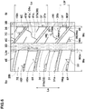
- Fig. 5 shows the axially inner first middle land subsection 4Bb and the center land region 4A.
- the axially inner first middle land subsection 4Bb between the first center main groove 3A and the first middle sub groove 5B is formed as a rib body extending continuously in the tire circumferential direction.
- the term "continuous" regarding the rib body means that the rib body is not divided in the tire circumferential direction by a transverse groove, and a sipe is not included in the above-mentioned transverse groove.
- the axially inner first middle land subsection 4Bb configured as such can increase the rigidity in the tire circumferential direction and the tire axial direction compared with a row of blocks completely divided from each other by transverse grooves.
- the maximum width Wg of the axially inner first middle land subsection 4Bb is set to be approximately 5.5% to 7.5% of the tread width TW.
- the axially inner first middle land subsection 4Bb is provided with a first inside middle chamfer portion 22 at the corner 21 between the ground contacting surface of the axially inner first middle land subsection 4Bb and a groove side wall of the first center main groove 3A.
- the first inside middle chamfer portion 22 has a slope face as with the first shoulder chamfer portion 10 shown in Fig. 4 .
- the first inside middle chamfer portions 22 are provided and arranged in the tire circumferential direction with substantially the same pitches as in the first middle chamfer portion 15 (shown in Fig. 3 ).
- the first inside middle chamfer portion 22 configured as such can increase the circumferential edge component in the axially inner first middle land subsection 4Bb, therefore, it is possible to improve the on-snow performance. Further, the first inside middle chamfer portion 22 can partially decrease the ground contacting area of the axially inner first middle land subsection 4Bb, therefore, it is possible to improve the wet performance.
- Both ends 22t in the tire circumferential direction of the first inside middle chamfer portion 22 terminate within the axially inner first middle land subsection 4Bb.
- step surfaces 23 extending in the tire axial direction are formed at the both ends 22tt of the first inside middle chamfer portion 22.
- the step surfaces 23, 23 configured as such can provide the axial edge component and scratch the snow in the tire circumferential direction, therefore, it is possible to improve the on-snow performance.
- step surfaces 23 in this embodiment are formed as triangles tapered toward the inside in the tire radial direction as with the step surfaces 11 shown in Fig. 4 . Thereby, it is possible to suppress the decrease in the rigidity of the first inside middle chamfer portion 22 and maintain the running performance on dry roads.
- the both ends 22t of the first inside middle chamfer portion 22 are formed as a tapered shape in the plan view.
- the first middle chamfer portion 22 configured as such can alleviate a stepped rigidity change from the non-chamfered corner 21 on both sides of the first inside middle chamfer portion 22 in the tire circumferential direction, therefore, it is possible to prevent the decrease in the steering stability.
- the width W3c, depth and length L3c of the first inside middle chamfer portion 22 in this embodiment are set in the same ranges as for the width L3b, depth D3b and length L3b of the first middle chamfer portion 15, respectively.
- the first middle land region 4B (the axially inner first middle land subsection 4Bb in this embodiment) is provided with first inside middle sipes 24 extending axially inwardly from a position axially inside the first middle rug groove 6B.
- the first inside middle sipe 24 configured as such can provide the first middle land portion 4B (the first inside middle land portion 4Bb) with the edges, therefore, it is possible to improve the on-ice performance.
- first inside middle sipe 24 is formed as an open sipe extending between the first center main groove 3A (the first inside middle chamfer portion 22) and the first middle sub groove 5B.
- first inside middle sipe 24 can provide the edges over the entire range of the axially inner first middle land subsection 4B, therefore, it is possible to improve the on-ice performance.
- the first inside middle sipe 24 is inclined with respect to the tire circumferential direction to the same direction as the first middle rug groove 6B.
- the first inside middle sipe 24 co-operates with the first middle rug groove 6B to provide an axial edge component and a circumferential edge component in a good balance, thereby, it is possible to improve the on-snow performance and the on-ice performance.
- the first inside middle sipe 24 extends axially outwardly from each end 22t of the first inside middle chamfer portion 22.
- the first inside middle sipes 24 co-operate with the respective step surface 23 formed at the both ends 22t of the first inside middle chamfer portion 22, and can provide the axial edge component, therefore, it is possible to improve the on-snow performance and the on-ice performance.
- the width and the depth of the first inside middle sipe 24 are set in the same range as for the width and the depth of the first shoulder sipe 12a, respectively. Further, it is preferable that an angle ⁇ 4e of the first inside middle sipe 24 with respect to the tire circumferential direction is set in the same range as for the angle ⁇ 2b (shown in Fig. 3 ) of the first middle rug groove 6B with respect to the tire circumferential direction.
- the first center land subsection 4Aa between the first center main groove 3A and the center sub groove 5A is applied by a relatively large load during straight running.
- the first center land subsection 4Aa is formed as a rib body extending continuously in the tire circumferential direction to ensure a high rigidity, therefore, it is possible to improve the steering stability on dry roads.
- the maximum width Wh of the first center land subsection 4Aa is set to be approximately 5.0% to 6.5% of the tread width TW.
- the first center land subsection 4Aa is provided with a first center chamfer portion 27 at the corner 26 between the ground contacting surface of the first center land subsection 4Aa and a groove side wall of the first center main groove 3A.
- the first center chamfer portion 27 has a slope face as with the first shoulder chamfer portion 10 shown in Fig. 4 .
- the first center chamfer portions 27 are provided and arranged in the tire circumferential direction with substantially the same pitches as in the first inside middle chamfer portion 22.
- the first center chamfer portion 27 configured as such can increase the circumferential edge component in the first center land subsection 4Aa, therefore, it is possible to improve the on-snow performance.
- the first center chamfer portion 27 can partially decrease the ground contact area of the first center land subsection 4Aa, therefore, it is possible to improve the wet performance.
- Both ends 27t in the tire circumferential direction of the first center chamfer portion 27 terminate within the first center land subsection 4Aa. Thereby, a step surface 28 extending in the tire axial direction is formed at each end 27t.
- the step surface configured as such can provide the axial edge component and scratch the snow in the tire circumferential direction, therefore, it is possible to improve the on-snow performance.
- the step surface 28 in this embodiment is formed as a triangle tapered toward the inside in the tire radial direction as with the step surface 11 shown in Fig.4 .
- the first chamfer portion 27 can alleviate a stepped rigidity change from the corner portion 26 on both sides of the first center chamfer portion 27, therefore, it is possible to prevent the decrease in the steering stability.
- the width W3d and the depth of the first center chamfer portion 27 in this embodiment are set in the same ranges as for the width W3b and the depth D3b of the first middle chamfer portion 15, respectively.
- the length L3d in the tire circumferential direction of the first center chamfer portion 27 is set to be smaller than the length L3a of the first shoulder chamfer portion 10, the length L3b of the first middle chamfer portion 15, and the length L3c of the first inside middle chamfer portion 22.
- the first center chamfer portion 27 can suppress the decrease in the rigidity of the center land region 4A to which region relatively large ground contact pressure is applied during straight running, therefore, it is possible to improve the steering stability on dry roads.
- the length L3a of the first center chamfer portion 27 is set in a range from 50% to 80% of the length L3a of the first shoulder chamfer portion 10.
- the first center chamfer portions 27 are shifted in the tire circumferential direction from the first inside middle chamfer portions 22 so that the first center chamfer portions 27 do not overlap with first inside middle chamfer portions 22. Thereby, the first center chamfer portion 27 and the first inside middle chamfer portion 22 can provide the edge components thoroughly in the tire circumferential direction on both sides of the first center main groove 3A.
- the first center land subsection 4Aa is provided with first center sipes 29 extending axially inwardly from the first center main groove 3A.
- the first center sipe 29 configured as such can provide edges for the first center land subsection 4Aa, therefore, it is possible to improve the on-ice performance.
- first center sipe 29 is formed as a semi-open sipe connected only with the first center main groove 3A. Thereby, the first center sipe 29 can suppress the decrease in the rigidity of the first center land subsection 4Aa, therefore, it is possible to maintain the steering stability on dry roads.
- the first center sipe 29 in this embodiment extends with an inclination with respect to the tire axial direction.
- the first center sipe 29 configured as such can provide a circumferential edge component and an axial edge component for the first center land subsection 4Aa.
- first center sipe 29 is inclined to the opposite direction to the first inside middle sipes 24 adjacent thereto with the first center main groove 3A therebetween.
- first center sipe 29 can provide the axial and circumferential edge components differently from those provided by the first inside middle sipe 24, therefore, it is possible to improve the on-ice performance.
- the first center sipes 29 in this embodiment include first center short sipes 29a and first center long sipes 29b which are arranged alternately in the tire circumferential direction, wherein the first center short sipes 29a are respectively connected to the first center chamfer portions 27, and the first center long sipes 29b are respectively connected to non-chamfered portions of the first center main groove 3A formed between the first center chamfer portions 27.
- the first center short sipe 29a and the first center long sipe 29b configured as such can provide the edges for the first center land subsection 4Aa thoroughly in the tire circumferential direction, therefore, it is possible to greatly improve the on-ice performance.
- the width and depth of the first center sipe 29 are set in the same range as for the width and depth of the first shoulder sipe 12a. Further, it is preferable that an angle ⁇ 4f of the first center sipe 29 with respect to the tire circumferential direction is set to be approximately 40 to 60 degrees.
- the above-mentioned second shoulder land region 4E is provided with second shoulder transverse grooves 6E extending from the second shoulder main groove 3D to the second tread edge 2Bt.
- the second shoulder land region 4E is circumferentially divided into second shoulder blocks 7E.
- the second shoulder transverse grooves 6E configured as such can improve the on-snow performance and the wet performance in the same manner as the first shoulder transverse groove 6D.
- Fig. 6 shows the second shoulder land region 4E and the second middle land region 4C.
- the second shoulder transverse groove 6E is inclined with respect to the tire axial direction.
- the second shoulder transverse groove 6E configured as such can provide an axial edge component and a circumferential edge component in a good balance, therefore, it is possible to improve the on-snow performance.
- the angle ⁇ 2e of the second shoulder transverse groove 6E with respect to the tire circumferential direction is gradually increased from the second shoulder main groove 3D toward the second tread edge 3Bt.
- the second shoulder transverse groove 6E configured as such can smoothly drain the water film on a road surface.
- the groove width W2e (shown in Fig. 1 ), the maximum groove depth D2e (shown in Fig. 2 ), and the angle ⁇ 2e (shown in Fig. 6 ) with respect to the tire circumferential direction of the second shoulder transverse groove 6E are set in the same ranges as for the groove width W2d, the maximum groove depth D2d and the angle ⁇ 2d of the first shoulder transverse groove 6D, respectively.
- the second shoulder block 7E is configured so that the maximum circumferential length Le thereof is approximately the same as the maximum axial width We thereof, and formed in the form of a parallelogram in the plan view.
- the second shoulder block 7E configured as such can improve its rigidity in the tire circumferential direction and the tire axial direction in a good balance, therefore, it is possible to improve the running performance on snowy roads and dry roads.
- the maximum length Le and the maximum width We of the second shoulder block 7E are set to be approximately 15% to 20% of the tread width TW.
- the second shoulder blocks 7E are each provided with a second shoulder chamfer portion 31 at the corner 30 between the ground contacting surface of the second shoulder block 7E and the adjacent groove side wall of the second shoulder main groove 3D.
- the second shoulder chamfer portion 31 has a slope face similarly to that shown in Fig. 4 .
- the second shoulder chamfer portion 31 configured as such can increase the circumferential edge component in the second shoulder block 7E, therefore, it is possible to improve the on-snow performance. Further, the second shoulder chamfer portion 31 can partially decrease the ground contacting area of the second shoulder block 7E, therefore, it is possible to improve the wet performance.
- one end 31a in the tire circumferential direction of the second shoulder chamfer portion 31 is connected to one of the adjacent second shoulder transverse grooves 6E, but the other end 31b in the tire circumferential direction of the second shoulder chamfer portion 31 terminates without reaching the second shoulder transverse grooves 6E.
- an step surface 32 extending in the tire axial direction is formed at the other end 31b of the second shoulder chamfer portion 31.
- the step surface 32 can provide an axial edge component and scratch the snow in the tire circumferential direction, therefore, it is possible to improve the on-snow performance.
- the ground contact pressure of the second shoulder block 7E becomes larger during cornering.
- the second shoulder chamfer portions 31 provided in the second shoulder block 7E like this can scratch the snow effectively during cornering, therefore, it is possible to greatly improve the on-snow performance.
- the step surface 32 is formed as a triangle tapered toward the inside in the tire radial direction as with the step surface 11 shown in Fig. 4 . Thereby, it is possible to suppress the decrease in the rigidity of the second shoulder block 7E and maintain the running performance on dry roads.
- the other end 31b of the second shoulder chamfer portion 31 is formed as a tapered shape in plan view.
- the second shoulder chamfer portion 31 configured as such can alleviate a stepped rigidity change from the corner portion 30 adjacent thereto in the tire circumferential direction, therefore, it is possible to prevent the decrease of the steering stability.
- the width W3e, the depth and the circumferential length L3e of the second shoulder chamfer portion 31 in this embodiment are set in the same ranges as for the width W3b, the depth D3b and the length L3b of the first middle chamfer portion 15, respectively.
- the second shoulder blocks 7E are each provided with a second shoulder rug groove 6F extending axially inwardly from the second tread edge 2Bt and terminating without reaching the second shoulder main groove 3D.
- the second shoulder rug groove 6F configured as such can improve the on-snow performance and the wet performance.
- the second shoulder rug groove 6F can suppress the decrease in the rigidity of the second shoulder block 7E, therefore, it is possible to improve the running performance on dry roads.
- the groove width W2f (shown in Fig. 1 ), and the groove depth of the second shoulder rug groove 6F are set in the same ranges as for the groove width W2b and the groove depth D2b of the first middle rug groove 6B, respectively.
- the angle ⁇ 2f (shown in Fig. 6 ) of the second shoulder rug groove 6F with respect to the tire circumferential direction is set in the same range as for the angle ⁇ 2e of the second shoulder transverse groove 6E.
- the second shoulder blocks 7E are each provided with a second shoulder sipe 33 extending axially outwardly from the second shoulder main groove 3D.
- the second shoulder sipe 33 in this embodiment extends axially outwardly from the end portion (the other end 31b) of the second shoulder chamfer portion 31.
- the second shoulder sipe 33 configured as such can provide the edges for the second shoulder block 7E, therefore, it is possible to improve the on-ice performance.
- the second shoulder sipe 33 co-operates with the step surface 32 of the second shoulder chamfer portion 31 and can provide an axial edge component, therefore, it is possible to improve the on-snow performance and the on-ice performance.
- the second shoulder sipe 33 is formed as an open sipe extending from the second shoulder main groove 3D (the other end 31b of the second shoulder chamfer portion 31) to the second shoulder rug groove 6F. Thereby, the second shoulder sipe 33 can provide the axial edge component over the wide range of the second shoulder block 7E in the tire axial direction, therefore, it is possible to improve the on-ice performance.
- the angle ⁇ 4g of the second shoulder sipe 33 with respect to the tire circumferential direction is approximately the same as the angle ⁇ 2e of the second shoulder transverse groove 6E so that the second shoulder sipe 33 and the second shoulder transverse groove 6E are inclined substantially in parallel with each other.
- the second shoulder sipe 33 configured as such can provide a circumferential edge component and an axial edge component for the second shoulder block 7E, therefore, it is possible to further improve the on-ice performance.
- the width and the depth of the second shoulder sipe 33 are set in the same ranges as for the width and the depth of the first shoulder sipe 12a, respectively.
- the second middle land region 4C is provided with second middle transverse grooves 6C extending from the second shoulder main groove 3D to the second center main groove 3B.
- the second middle land region 4C is circumferentially divided into second middle blocks 7C.
- the second middle transverse groove 6C configured as such can improve the on-snow performance and the wet performance.
- the second middle transverse groove 6C is inclined with respect to the tire axial direction.
- the second middle transverse groove 6C configured as such can provide a circumferential edge component and an axial edge component in a good balance, therefore, it is possible to improve the on-snow performance.
- the groove width W2c and the maximum groove depth D2c (shown in Fig. 2 ) of the second middle transverse groove 6C are set in the same ranges as for the groove width W2b and the maximum groove depth D2b of the first middle rug groove 6B.
- the angle ⁇ 2b (shown in Fig. 6 ) of the second middle transverse groove 6C with respect to the tire circumferential direction is set in a range from 45 to 60 degrees.
- the second middle block 7C is configured such that the a maximum circumferential length LC thereof is larger than the maximum axial width WC thereof and formed as a parallelogram in the plan view.
- the second middle block 7C configured as such can relatively increase its rigidity in the tire circumferential direction, therefore, it is possible to improve the running performance on snowy roads and dry roads.
- the maximum length LC of the second middle block 7C is approximately 22% to 27% of the tread width.
- the maximum width WC of the second middle block 7C is approximately 12% to 17% of the tread edge TW.
- the second middle block 7C has an edge abutting on the second middle transverse groove 6C and an edge abutting on the second center main groove 3B, and an acute angled corner 48 formed between these edges is cambered.
- the corner 48 on the second center main groove 3B side where the ground contact pressure becomes relatively high during straight running and cornering can be prevented from becoming a start point from which a tearing-off of the block occurs.
- the second middle blocks 7C are each provided with a second middle chamfer portion 37 at the corner 36 between the ground contacting surface of the second middle block 7C and the adjacent groove side wall of the second center main groove 3B.
- the second middle chamfer portion 37 has a slope face as with the first shoulder chamfer portion 10 shown in Fig. 4 .
- the second middle chamfer portion 37 configured as such can increase the circumferential edge component of the second middle block 7C, therefore, it is possible to improve the on-snow performance.
- the second middle chamfer portion 37 can partially decrease the ground contacting area of the second middle block 7C, therefore, it is possible to improve the wet performance.
- the second middle chamfer portion 37 is configured such that one end 37a thereof in the tire circumferential direction is connected to one of the adjacent second middle transverse grooves 6C, and the other end 37b thereof in the tire circumferential direction terminates without reaching the other second middle transverse groove 6C.
- a step surface 38 extending in the tire axial direction is formed at the other end 37b of the second middle chamfer portion 37.
- the step surface 38 configured as such can provide an axial edge component and scratch the snow in the tire circumferential direction, therefore, it is possible to improve the on-snow performance.
- the step surface 38 in this embodiment is formed as a triangle tapered toward the inside in the tire radial direction as with the step surface 11 shown in Fig. 4 .
- the second middle chamfer portion 37 can suppress the decrease in the rigidity of the second middle block 7C and maintain the running performance on dry roads.
- the other end 37b of the second middle chamfer portion 37 is formed as a tapered shape in the plan view.
- the second middle chamfer portion 37 configured as such can alleviate a stepped rigidity change from the corner portion 36 adjacent thereto in the tire circumferential direction, therefore, it is possible to prevent the decrease in the steering stability.
- the width W3f, the depth, and the circumferential length L3f of the second middle chamfer portion 37 in this embodiment are set in the same ranges as for the width W3a, the depth D3a, and the length L3a of the first shoulder chamfer portion 10, respectively.
- the width W3f and the depth of the second middle chamfer portion 37 are set to be smaller than the width W3b and the depth D3b of the first middle chamfer portion 15, therefore, it is possible to suppress the decrease in the rigidity of the second middle block 7C and maintain the running performance on dry roads.
- the second middle blocks 7C are each provided with second middle sipes 39 to provide edges for the second middle block 7C, therefore, it is possible to improve the on-ice performance.
- the width and the depth of the second middle sipe 39 are set in the same ranges as for the width and the depth of the first shoulder sipe 12a, respectively.
- the second middle sipes 39 include a second outside middle sipe 39a connected to the second shoulder main groove 3D, a second inside middle sipe 39b connected to the second center main groove 3B, and a second center middle sipe 39c extending between the adjacent second middle transverse grooves 6C.
- the second outside middle sipe 39a extends axially inwardly from the second shoulder main groove 3D and terminates without reaching the second center main groove 3B.
- the second outside middle sipe 39a configured as such can provide edges, while maintain the rigidity of the second middle block 7C.
- the second outside middle sipe 39a is inclined with respect to the tire circumferential direction. Thereby, the second outside middle sipe 39a can thoroughly provide a circumferential edge component and an axial edge component.
- the angle ⁇ 4h of the second outside middle sipe 39a with respect to the tire circumferential direction is set in a range from 45 to 65 degrees.
- the second inside middle sipe 39b extends axially outwardly from an end (the other end 37b) of the second middle chamfer portion 37 and terminates without reaching the second shoulder main groove 3D.
- the second inside middle sipe 39b configured as such can suppress the decrease in the rigidity of the second middle block 7C, while providing edge components for the second middle block 7C.
- the second inside middle sipe 39b co-operates with the step surface 38 of the second middle chamfer portion 37 and can provide an axial edge component, therefore, it is possible to improve the on-snow performance and the on-ice performance.
- the second inside middle sipe 39b is inclined with respect to the tire circumferential direction.
- the second inside middle sipe 39b can thoroughly provide a circumferential edge component and an axial edge component.
- an angle ⁇ 4i of the second inside middle sipe 39b with respect to the tire circumferential direction is set in the same range as for the angle ⁇ 4h of the second outside middle sipe 39a.
- the second center middle sipe 39c is composed of a center portion 41a, an inside portion 41b and an outside portion 41c.
- the center portion 41a extends straight along the tire axial direction in the central portion in the tire axial direction of the second middle block 7C, and terminates without reaching the second shoulder main groove 3D and the second center main groove 3B.
- the inside portion 41b extends from the axially inner end of the center portion 41a to one of the adjacent second middle transverse grooves 6C
- the outside portion 41c extends from the axially outer end of the center portion 41a to the other second middle transverse groove 6C.
- the second center middle sipe 39c configured as such can provide the axial and circumferential edge components for the second middle block 7C over the wide range in the tire circumferential direction, therefore, it is possible to improve the on-ice performance.
- the angle ⁇ 4k of the inside portion 41b with respect to the tire circumferential direction, and the angle ⁇ 4m of the outside portion 41c with respect to the tire circumferential direction are set to be smaller than the angle ⁇ 4j of the center portion 41a with respect to the tire circumferential direction.
- the second center middle sipe 39c is configured to be bended to form a crank shape, therefore, it is possible to provide the axial and circumferential edge components thoroughly in the tire circumferential direction and the tire axial direction.
- the angle ⁇ 4k of the inside portion 41b and the angle ⁇ 4m of the outside portion 41c are set in a range from be 15 to 35 degrees. It is desirable that the angle ⁇ 4j of the center portion 41a is set in a range from 70 to 90 degrees.
- the second center land subsection 4Ab between the second center main groove 3B and the center sub groove 5A is applied by a relatively large load during straight running.
- the second center land subsection 4Ab is formed as a rib body extending continuously in the tire circumferential direction to ensure a high rigidity, therefore, it is possible to improve the steering stability on dry roads.
- the maximum width wi of the second center land subsection 4Ab is set in the same range as for the maximum width wh of the first center land subsection 4Aa.
- the second center land subsection 4Ab is provided with second center chamfer portions 45 at the corner 43 between the ground contacting surface of the second center land subsection 4Ab and the adjacent groove side wall of the second center main groove 3B.
- the second center chamfer portion 45 has a slope face as with the first shoulder chamfer portion 10 shown in Fig. 4 .
- the second center chamfer portions 45 are provided and arranged in the tire circumferential direction with substantially the same pitches as the first center chamfer portion 27.
- the second center chamfer portion 45 configured as such can increase the circumferential edge component of the second center land subsection 4Ab, therefore, it is possible to improve the on-snow performance. Further, the second center chamfer portion 45 can partially decrease the ground contacting area of the second center land subsection 4Ab, therefore, it is possible to improve the wet performance.
- Both ends 45t in the tire circumferential direction of the second center chamfer portion 45 terminate within the second center land subsection 4Ab.
- step surfaces 46 extending in the tire axial direction are formed at the both ends 45t of the second center chamfer portion 45.
- the step surfaces 46 configured as such provide an axial edge component and can scratch the snow in the tire circumferential direction, therefore, it is possible to improve the on-snow performance.
- step surface 46 in this embodiment is formed as a triangle tapered toward the inside in the tire radial direction as with the step surface 11 shown in Fig, 4 .
- the both ends 45t of the second center chamfer portion 45 are each formed as a tapered shape in the plan view.
- the second chamfer portion 45 configured as such can alleviate a stepped rigidity change from non-chamfered corner portions 43 on both sides of the second center chamfer portion 45 in the tire circumferential direction, therefore, it is possible to prevent the decrease in the steering stability.
- the width W3g and the depth of the second center chamfer portion 45 in this embodiment are set in the same ranges as for the width W3d and the depth of the first center chamfer portion 27.
- the length L3g (shown in Fig. 5 ) in the tire circumferential direction of the second center chamfer portion 45 is set to be smaller than the length L3e of the second shoulder chamfer portion 31 and the length L3f of the second middle chamfer portion 37 shown in Fig. 6 .
- the second center chamfer portion 45 can prevent the decrease in the rigidity of the center land region 4A to which relatively large ground contacting pressure is applied during straight running, therefore, it is possible to improve the running performance on dry roads.
- the length L3g of the second center chamfer portion 45 is set in the same range as for the length L3d of the first center chamfer portion 27.
- the second center chamfer portions 45 are sifted in the tire circumferential direction from the second middle chamfer portions 37. Thereby, the second center chamfer portions 45 and the second middle chamfer portions 37 can provide the edge components thoroughly in the tire circumferential direction on both sides of the second center main groove 3B.
- the second center chamfer portions 45 are shifted in the tire circumferential direction from the first center chamfer portions 27.
- the second center chamfer portions 45 and the first center chamfer portions 27 can provide the edge components thoroughly in the tire circumferential direction on both sides of the second center main groove 3B.
- the second center land subsection 4Ab in this embodiment is provided with second center sipes 47 extending axially inwardly from the second center main groove 3B (the second center chamfer portion 45).
- the second center sipe 47 configured as such can provide the edges for the second center land subsection 4Ab, therefore, it is possible to improve the on-ice performance.
- the second center sipe 47 in this embodiment is formed as a semi-open sipe connected only with the second center main groove 3B (the second center chamfer portion 45).
- the second center sipe 47 can maintain the rigidity of the second center land subsection 4Ab, therefore, it is possible to maintain the running performance on dry roads.
- the second center sipe 47 in this embodiment extends with an inclination with respect to the tire axial direction to provide a circumferential edge component and an axial edge component. Moreover, the second center sipe 47 is inclined to the opposite direction to the second inside middle sipe 39b adjacent thereto with the second center main groove 3B therebetween. Thereby, the second center sipe 47 can provide axial and circumferential edge components differently from those provided by the second inside middle sipe 39b, therefore, it is possible to improve the on-ice performance.
- the second center sipes 47 in this embodiment include second center short sipes 47a and second center long sipes 47b arranged alternately in the tire circumferential direction.
- the second center short sipes 47a are connected to the respective second center chamfer portions 45, and the second center long sipes 47b are connected to the second center main groove 3B between the second center chamfer portions 45.
- the second center short sipes 47a and the second center long sipes 47b can provide the edges for the second center land subsection 4Ab thoroughly in the tire circumferential direction, therefore, it is possible to greatly improve the on-ice performance.
- the width, the depth and the angle ⁇ 4n with respect to the tire circumferential direction of the second center sipe 47 are set in the same ranges as for the width, the depth and the angle ⁇ 4f of the first center sipe 29, respectively.
- the tread pattern is bound with the tire mounting position such that, when the tire is mounted on a vehicle, the first half-tread portion 2A is located toward the inside Si of the vehicle and the second half-tread portion 2B is located toward the outside So of the vehicle.
- the present invention is not limited to the illustrated embodiment.
- the present invention can be embodied such that, when the tire is mounted on a vehicle, the first half-tread portion 2A is located toward the outside of the vehicle and the second half-tread portion 2B is located toward the inside of the vehicle, for example.
- the first middle chamfer portions 15 and the first shoulder chamfer portions 10 are provided in the first middle land region 4B and the first shoulder land region 4D to which a relatively large ground contact pressure is applied during cornering, therefore, it is possible to scratch the snow efficiently during cornering. Further, the first middle chamfer portions 15 and the first shoulder chamfer portions 10 co-operate to scratch the snow during running straight when relatively small ground contacting pressure is applied to the first middle land region 4B and the first shoulder land region 4D.
- the tire 1 of the present invention can improve the on-snow performance efficiently.
- test tires as Working examples Ex.1 to Ex.8 having specifications listed in Table 1 were manufactured.
- a test tire as Comparative example Ref.1 having a tread pattern shown in Fig. 7(a) with the first middle chamfer portions shifted from the first shoulder chamfer portions and a test tire as Comparative example Ref.2 having a tread pattern shown in Fig. 7(b) without the first shoulder chamfer portions were also manufactured.
- Second center land region Second center land region
- Second center main groove Second center main groove
- Second shoulder transverse groove Second shoulder transverse groove
- Second middle chamfer portion
- First outside middle sipe First center middle sipe:
- test tires were tested as follows.
- Test tires were mounted on all of the wheels of the test car. Then, during the test car running on a road surface covered with snow (not compressed snow) of a test course, the test driver evaluated the on-snow performance based on the steering response, rigid impression, grip and the like. The results are indicated by an index based on Working example Ex. 1 being 100, wherein the larger numeric value is better.
- test car was driven on a road surface covered with ice of the test course, and the driver evaluated the on-ice performance based on the steering response, rigid impression, grip and the like.
- the results are indicated by an index based on Working example Ex. 1 being 100, wherein the larger numeric value is better.
- test car was driven on a dry asphalt road surface of a test course, and the test driver evaluated the running performance based on the steering response, rigid impression, grip and the like.
- the results are indicated by an index based on Working example Ex. 1 being 100, wherein the larger numeric value is better.
- the test car was driven at a speed of 65 km/h on a wet asphalt road surface covered with 0.5 to 2.0 mm depth water, and the brakes were applied while driving, then the distance needed for the test car speed to decrease from 60 km/h to 20 km/h was measured.
- the results are indicated by an index based on Working example Ex. 1 being 100, wherein the larger numeric value is better.
- Table 1 Ref.1 Ref.2 Ex.1 Ex.2 Ex.3 Ex.4 Ex.5 Ex.6 Ex.7 Ex.8 Developed view of Tread portion Fig. 7(a) Fig. 7(b) Fig. 7(a) Fig. 7(a) Fig. 7(a) Fig. 7(a) Fig. 7(a) Fig. 7(a) Fig. 7(a) Fig. 7(a) Fig. 7(a) Fig. 7(a) Fig. 7(a) Fig. 7(a) Fig. 7(a) Fig. 7(a) Fig.
Landscapes
- Engineering & Computer Science (AREA)
- Mechanical Engineering (AREA)
- Tires In General (AREA)
Abstract
Description
- The present invention relates to a tire with improved on-snow performance.
- Japanese Patent Application Publication No.
2013-177114
Further, the corner of the land region formed between the ground contacting surface of the land region and a groove side wall of the main groove is provided with chamfer portions. Both ends in the tire circumferential direction of the chamfer portion are connected to the adjacent rug groove and the adjacent transverse groove, respectively. - Each of the chamfer portions disclosed in the
Patent Literature 1 has its both ends connected to the rug groove and the transverse groove, therefore it is unable to increase the axial component of the edges. Further, in thePatent Literature 1, the land region is not provided with additional chamfer portions at opposite positions to the chamfer portions. Thus, the chamfer portions disclosed in thePatent Literature 1 cannot increase the edge effect sufficiently, and accordingly, it is difficult to improve the on-snow performance. - The present invention was made in view of the above, and a primary object thereof is to provide a pneumatic tire capable of improving the on-snow performance.
- According to the present invention, a tire comprises
a tread portion having a first half-tread portion located on one side of the tire equator in the tire axial direction and a second half-tread portion on the other side of the tire equator in the tire axial direction,
the first half-tread portion provided with a first shoulder main groove extending continuously in the tire circumferential direction on its most tread-edge side, a first shoulder land region formed axially outside the first shoulder main groove, and
a first middle land region formed axially inside the first shoulder main groove,
wherein
the first shoulder land region is circumferentially divided into first shoulder blocks by first shoulder transverse grooves extending from the first shoulder main groove to the adjacent tread edge,
each of the first shoulder blocks has a first shoulder chamfer portion at a corner between a ground contacting surface of the first shoulder block and a groove side wall of the first shoulder main groove,
both ends in the tire circumferential direction of the first shoulder chamfer portion terminate without being connected to the adjacent first shoulder transverse grooves,
the first middle land region is provided with first middle rug grooves extending axially inwardly from the first shoulder main groove and terminating within the first middle land region, and
first middle chamfer portions each formed at a corner between a ground contacting surface of the first middle land portion and the adjacent side wall of the first shoulder main groove in a part of the range between a pair of the adjacent first middle rug grooves, and
the first middle chamfer portions are disposed so as to overlap in the tire circumferential direction with the first shoulder chamfer portions of the first shoulder blocks. - Further, the tire according the present invention may have the following features (1)-(6):
- (1) the first middle land region is provided with first inside middle sipes extending axially inwardly from positions axially inside the first middle rug grooves, and
the first inside middle sipes are inclined to the same direction as the first middle rug grooves; - (2) the first middle land region is provided with first outside middle sipes extending axially inwardly from the first shoulder main groove, and each disposed between a pair of the first middle rug grooves adjacent in the tire circumferential direction, and further each connected to an end in the tire circumferential direction of one of the first middle chamfer portions;
- (3) the first shoulder block is provided with a pair of first shoulder sipes extending axially outwardly from said both ends of the first shoulder chamfer portion;
- (4) the second half-tread portion is provided with a second shoulder main groove extending continuously in the tire circumferential direction on its most tread-edge side, and
a second shoulder land region located axially outside the second shoulder main groove,
the second shoulder land region is circumferentially divided into second shoulder blocks by second shoulder transverse grooves extending from the second shoulder main groove to a tread edge, and
each of the second shoulder blocks is provided with a second shoulder chamfer portion at a corner between a ground contacting surface of the second shoulder block and a groove side wall of the second shoulder main groove in a part of the range between a pair of the second shoulder transverse grooves adjacent in the tire circumferential direction; - (5) the second shoulder block is provided with a second shoulder sipe extending axially outwardly from the second shoulder main groove, and
the second chamfer portion extends in the tire circumferential direction from the second shoulder sipe to one of said pair of the second shoulder transverse grooves adjacent in the tire circumferential direction; - (6) the tread portion is provided with a tread pattern whose position when the tire is mounted on a vehicle is specified such that the first half-tread portion and the second half-tread portion are respectively located toward the inside and outside of the vehicle.
- In the tire according to the present invention, the first half-tread portion located one side of the tire equator in the tire axial direction is provided with the first shoulder main groove extending continuously in the tire circumferential direction on its most tread-edge side, the first shoulder land region disposed axially outside the first shoulder main groove, and the first middle land region disposed axially inside the first shoulder main groove.
The first main groove configured as such compresses the snow into the groove and shears the compresses the snow, therefore, it is possible to improve on-snow performance. - The first shoulder land region is divided into the first shoulder blocks by the first shoulder transverse grooves extending from the first shoulder main groove to the tread edge. The first shoulder transverse grooves configured as such compress the snow into the grooves and shear the compressed snow, therefore, it is possible to improve the on-snow performance.
- The first shoulder blocks each have the first shoulder chamfer portion at the corner between the ground contacting surface of the first shoulder block and the groove side wall of the first shoulder main groove. The first chamfer portion configured as such can increase the circumferential edge component, therefore, it is possible to improve the on-snow performance.
- The both ends in the tire circumferential direction of the first shoulder chamfer potion terminate without being connected to the first shoulder transverse grooves. Thereby, an step surface extending in the tire axial direction is formed in the first shoulder transverse groove. Such step surface provides an axial edge component and can scratch the snow in the tire circumferential direction, therefore, it is possible to improve the on-snow performance.
- The first middle land region is provided with the first middle rug grooves extending axially inwardly from the first shoulder main groove and terminating within the first middle land region, and the first middle chamfer portions each formed at the corner between the ground contacting surface of the first middle land region and the groove side wall of the first shoulder main groove in a part of the range between a pair of the first middle rug grooves adjacent in the tire circumferential direction.
The first middle rug groove compresses the snow into the groove and shears it, therefore, it is possible to improve the on-snow performance. Further, the first middle chamfer portion can increase the circumferential edge component and can improve the on-snow performance. Furthermore, since the first middle chamfer portion is formed in a part of the range between a pair of the first middle rug grooves, a step surface extending in the tire axial direction is formed. Such step surface provides an axial edge component and can scratch the snow in the tire circumferential direction, therefore, it is possible to improve the on-snow performance. - The first middle chamfer portions are disposed so as to face the first shoulder chamfer portions. Thereby, the first middle chamfer portions and the first shoulder chamfer portions contact with the ground at the same time, therefore it is possible to greatly increase the edge components and scratch the snow efficiently. Thus, the tire according to the present invention can improve the on-snow performance.
- in this application including specification and claims, various dimensions, positions and the like of the tire refer to those under a normally inflated unloaded condition of the tire unless otherwise noted.
- The normally inflated unloaded condition is such that the tire is mounted on a standard wheel rim and inflated to a standard pressure but loaded with no tire load.
- The undermentioned normally inflated loaded condition is such that the tire is mounted on the standard wheel rim and inflated to the standard pressure and loaded with the standard tire load.
- The standard wheel rim is a wheel rim officially approved or recommended for the tire by standards organizations, i.e. JATMA (Japan and Asia), T&RA (North America), ETRTO (Europe), TRAA (Australia), STRO (Scandinavia), ALAPA (Latin America), ITTAC (India) and the like which are effective in the area where the tire is manufactured, sold or used. The standard pressure and the standard tire load are the maximum air pressure and the maximum tire load for the tire specified by the same organization in the Air-pressure/Maximum-load Table or similar list.
For example, the standard wheel rim is the "standard rim" specified in JATMA, the "Measuring Rim" in ETRTO, the "Design Rim" in TRA or the like. The standard pressure is the "maximum air pressure" in JATMA, the "Inflation Pressure" in ETRTO, the maximum pressure given in the "Tire Load Limits at Various Cold Inflation Pressures" table in TRA or the like. The standard load is the "maximum load capacity" in JATMA, the "Load Capacity" in ETRTO, the maximum value given in the above-mentioned table in TRA or the like.
In case of passenger car tires, however, the standard pressure and standard tire load are uniformly defined by 180 kPa and 88 % of the maximum tire load, respectively. - The tread edges (first tread edge 2At, second tread edge 2Bt) are the axial outermost edges of the ground contacting patch which occurs under the normally inflated loaded condition when the camber angle of the tire is zero.
- The tread width TW is the width measured under the normally inflated unloaded condition, as the axial distance between the tread edges determined as above.
-
-
Fig. 1 is a developed view of the tread portion of a tire as an embodiment of the present invention. -
Fig. 2 is a schematic cross-sectional view of the tread portion (reinforcing cord layers therein are omitted) taken along line A1-A1 inFig. 1 . -
Fig. 3 is a magnified view of the first shoulder land region and the first middle land region. -
Fig. 4 is a perspective partial view showing the first shoulder chamfer portion and the first middle chamfer portion. -
Fig. 5 is a magnified view of a first middle land subsection and a center land region. -
Fig. 6 is a magnified view of the second shoulder land region and a second middle land region. -
Fig. 7(a) is a developed view of the tread portion of Comparative example 1. -
Fig. 7(b) is a developed view of the tread portion of Comparative example 2. - Embodiments of the present invention will now be described in detail in conjunction with accompanying drawings. The present invention can be applied to various tires, and suitably applied to a radial tire for passenger cars.
Fig. 1 shows thetread portion 2 of a passenger car radial tire as an embodiment of the present invention. - The
tread portion 2 in this embodiment has a left-right asymmetric tread pattern for which a mounting position on a vehicle is specified. The mounting position is indicated in a sidewall portion and the like of thetire 1 by characters ("INSIDE" and/or "OUTSIDE", for example) and so on (not shown in the figures). - The
tread portion 2 has a first half-tread portion 2A located on one side of the tire equator C in the tire axial direction, and a second half-tread portion 2B located on the other side of the tire equator in the tire axial direction. when the tire is mounted on a vehicle, the first half-tread portion 2A is located toward the inside Si of the vehicle, and the second half-tread portion 2B is located toward the outside So of the vehicle. - The first half-
tread portion 2A is provided with
a first shouldermain groove 3C extending continuously in the tire circumferential direction on its most tread-edge 2At side (hereafter, also referred to as "first tread edge"), a firstshoulder land region 4D disposed axially outside the first shouldermain groove 3C, and
a firstmiddle land region 4B disposed axially inside the first shouldermain groove 3C. - Further, the first half-
tread portion 2A in this embodiment is provided with a first centermain groove 3A extending continuously in the tire circumferential direction between the tire equator C and the first shouldermain groove 3C. In this embodiment, therefore, the firstmiddle land region 4B is defined as being between the first shouldermain groove 3C and the first centermain groove 3A. - The second half-
tread portion 2B is provided with
a second shouldermain groove 3D extending continuously in the tire circumferential direction on its most tread-edge 2Bt side (hereafter, also referred to as "second tread edge"), a secondshoulder land region 4E disposed axially outside the second shouldermain groove 3D, and
a secondmiddle land region 4C disposed axially inside the second shouldermain groove 3D. - Further, the second half-
tread portion 2B in this embodiment is provided with a second centermain groove 3B extending continuously in the tire circumferential direction between the tire equator C and the second shouldermain groove 3D.
In this embodiment, therefore, the secondmiddle land region 4C is defined as being between the second shouldermain groove 3D and the second centermain groove 3B. - In this embodiment, the
tread portion 2 is provided with acenter land region 4A axially divided by the first centermain groove 3A and the second centermain groove 3B. Thecenter land region 4A is provided with acenter sub groove 5A extending continuously in the tire circumferential direction on the tire equator C.
Thereby, thecenter land region 4A is composed of
a first center land subsection 4Aa defined between thecenter sub groove 5A and the first centermain groove 3A, and a second center land subsection 4Ab defined between thecenter sub groove 5A and the second centermain groove 3B. The first center land subsection 4Aa is located in the first half-tread portion 2A, and the second center land subsection 4Ab is located in the second half-tread portion 2B. - In general, the circumferential length of the ground contacting patch of a pneumatic tire under the normally-inflated normally-loaded state decreases from the tire equator toward the tread edges, and accordingly, the ground contact tends to decrease toward the axially outsides.
- In this embodiment, in the ground contacting patch of
the tire under the normally inflated normally loaded state,
a maximum axial width Wa of thecenter land region 4A,
a maximum axial width Wb of the firstmiddle land region 4B,
a maximum axial width Wc of the secondmiddle land region 4C,
a maximum axial width Wd of the firstshoulder land region 4D,
and
a maximum axial width We of the secondshoulder land region 4E are formed to satisfy the following relationship:
respective land regions
In order to exert such effects efficiently, it is preferred that the maximum axial width Wb of the firstmiddle land region 4B and
the maximum axial width Wc of the secondmiddle land region 4C are 120% to 130% of the maximum axial width Wa of thecenter land region 4A.
Further, it is preferred that the maximum axial width Wd of the firstshoulder land region 4D, and the maximum axial width We of the secondshoulder land region 4E are 130% to 150 % of the maximum axial width Wa of thecenter land region 4A. - The first shoulder
main groove 3C and the second shouldermain groove 3D are formed as straight grooves extending straight along the tire circumferential direction. The first shouldermain groove 3C and the second shouldermain groove 3D configured as such compress the snow thereinto to form snow blocks, and shear the snow blocks to obtain larger shearing force. Thereby, it is possible to improve the on-snow performance. - Further, the first shoulder
main groove 3C and the second shouldermain groove 3D can guide the water film on the road surface toward the tire circumferential direction, therefore, it is possible to improve the wet performance. - The groove width W1c of the first shoulder
main groove 3C and the groove width W1d of the second shouldermain groove 3D are set to be approximately 3% to 8% of the tread width TW. - Further, the groove depth D1c (shown in
Fig. 2 ) of the first shouldermain groove 3C and the groove depth D1d (shown inFig. 2 ) of the second shouldermain groove 3D are set to be approximately 3% to 7% of the tread width TW. - The first center
main groove 3A and the second centermain groove 3B are formed as straight grooves extending straight along the tire circumferential direction in the same way as the first shouldermain groove 3C and the second shouldermain groove 3D. The first centermain groove 3A and the second centermain groove 3B configured as such can improve the on-snow performance and the wet performance in the same way as the first shouldermain groove 3C and the second shouldermain groove 3D. - It is preferable that the groove width W1a of the first center
main groove 3A and the groove width W1b of the second centermain groove 3B are set to be in the same range as for the groove width W1c of the first shouldermain groove 3C and the groove width W1d of the second shouldermain groove 3D, namely, approximately 3% to 8% of the tread width TW. - Further, as shown in
Fig.2 , it is preferable that the groove depth D1a of the first centermain groove 3A and the groove depth D1b of the second centermain groove 3B are set to be in the same range as for the groove depth D1c of the first shouldermain groove 3C and the groove depth D1d of the second shouldermain groove 3D, namely, approximately 3% to 7% of the tread width TW. - As shown in
Fig. 1 , thecenter sub groove 5A is formed as a straight groove extending straight along the tire circumferential direction. Thecenter sub groove 5A configured as such can improve the on-snow performance and the wet performance in the same way as each of themain grooves - The groove width W1e of the
center sub groove 5A is smaller than the groove width W1a of the first centermain groove 3A. Further, as shown inFig. 2 , the groove depth D1e of thecenter sub groove 5A is smaller than the groove depth D1a of the first centermain groove 3A. Thecenter sub groove 5A configured as such can prevent the decrease in the rigidity of the first center land subsection 4Aa, therefore, it is possible to maintain the running performance on dry roads. - In order to exert such effects efficiently, it is preferred that the groove width W1e of the
center sub groove 5A is set in a range from 0.5% to 1.0% of the tread width TW as shown inFig. 1 . Further, it is preferred that the groove depth D1e (shown inFIG. 2 ) of thecenter sub groove 5A is set in a range from 1% to 2 % of the tread width TW. - The first
shoulder land region 4D is provided with the first shouldertransverse grooves 6D extending from the first shouldermain groove 3C to the first tread edge 2At. Thereby, the firstshoulder land region 4D is circumferentially divided into thefirst shoulder blocks 7D. - The first shoulder
transverse grooves 6D configured as such compress the snow thereinto to form snow blocks, and shear the snow blocks to obtain larger shearing force. Thereby, it is possible to improve the snow performance. - Further, the first shoulder
transverse grooves 6D can guide the water film on the road surface toward the first shouldermain groove 3C and the first tread edge 2At. Therefore, it is possible to improve the wet performance. - The first shoulder
transverse grooves 6D are inclined with respect to the tire axial direction. The edges of the first shouldertransverse grooves 6D configured as such can provide a circumferential component and an axial component in a good balance to improve the on-snow performance. Moreover, the angle α2d of the first shouldertransverse groove 6D with respect to the tire circumferential direction is gradually increased from the first shouldermain groove 3C toward the first tread edge 2At in order to drain the water film on the road surface smoothly. - In order to exert such effects efficiently, it is preferred that the groove width W2d of the first shoulder
transverse groove 6D is set in a range from 2% to 5% of the tread width TW.
Further, as shown inFig. 2 , it is preferable that the maximum groove depth D2d of the first shouldertransverse groove 6D is set to be approximately 2.5% to 4.5% of the tread width TW. Furthermore, it is preferable that the angle α2d is set in a range from 70 to 90 degrees, for example. - The
first shoulder blocks 7D are each configured so that the maximum length Ld thereof in the tire circumferential direction is substantially the same as the maximum width Wd thereof in the tire axial direction, and formed as a parallelogram in the plan view. Thefirst shoulder block 7D configured as such can be increased in its rigidity in the tire circumferential direction and the tire axial direction in a good balance, therefore, it is possible to improve the running performance on snowy roads and dry roads.
Preferably, the maximum length Ld and the maximum width Wd of thefirst shoulder block 7D are approximately 15 to 20 % of the tread width TW. -
Fig. 3 shows the firstshoulder land region 4D and the firstmiddle land region 4B.Fig. 4 shows a firstshoulder chamfer portion 10 and a firstmiddle chamfer portion 15. Each of thefirst shoulder blocks 7D is provided with a firstshoulder chamfer portion 10 at thecorner 8 between the ground contacting surface of thefirst shoulder block 7D and a groove side wall of the first shouldermain groove 3C. The firstshoulder chamfer portion 10 has a slope face as shown inFigs. 3 and4 .
The firstshoulder chamfer portion 10 configured as such can increase the circumferential component of the edges of thefirst shoulder block 7D to improve the on-snow performance. Further, the firstshoulder chamfer portion 10 can partially decrease the ground contacting area of thefirst shoulder block 7D, therefore, it is possible to improve the wet performance. - Both ends 10t in the tire circumferential direction of the first
shoulder chamfer portion 10 terminate without being connected to the first shouldertransverse grooves 6D, and step surfaces 11 extending in the tire axial direction are formed at theends 10t. The step surfaces 11 can provide an axial edge component to scratch the snow in the tire circumferential direction, therefore, it is possible to improve the on-snow performance. - Further, the step surfaces 11 in this embodiment are formed in the form of a triangle which is tapered toward the inside in the tire radial direction. Thereby, it is possible to suppress the decrease in the rigidity of the
first shoulder block 7D, and to maintain the running performance on dry roads. - If the width W3a of the first
shoulder chamfer portion 10 is small, sufficient edge components cannot be provided, and it becomes difficult to improve the on-snow performance. Moreover, as the ground contacting area of thefirst shoulder block 7D cannot be decreased sufficiently to improve the wet performance.
If the width W3a of the firstshoulder chamfer portion 10 is large, thefirst shoulder block 7D is decreased in the rigidity, and it becomes difficult to surely maintain the running performance on dry roads.
From these points of view, the width W3a of the firstshoulder chamfer portion 10 is preferably not less than 0.8 mm, more preferably not less than 1.0 mm, and preferably not greater than 2.5 mm, more preferably not greater than 2.0 mm. - From similar points of view, a depth D3a (shown in
Fig. 4 ) of the firstshoulder chamfer portion 10 is preferably not less than 30 %, more preferably not less than 40 %, and preferably not greater than 60 %, more preferably not greater than 50 % of the groove depth D1a (shown inFig. 2 ) of the first shouldermain groove 3C. - Further, the length L3a (shown in
Fig. 3 ) in the tire circumferential direction of the firstshoulder chamfer portion 10 is preferably not less than 40 %, more preferably not less than 45 %, and preferably not greater than 80 %, more preferably not greater than 60% of the maximum length Ld (shown inFig. 1 ) of thefirst shoulder block 7D. - The
first shoulder block 7D is, as shown inFig. 3 , provided with a pair offirst shoulder sipes 12a which respectively extend axially outwardly from the both ends 10t of the firstshoulder chamfer portion 10. A pair of thefirst shoulder sipes 12a can increase the edges of thefirst shoulder block 7D, therefore, it is possible to improve the on-ice performance. Moreover, a pair of thefirst shoulder sipes 12a co-operates with the step surfaces 11 formed at the both ends 10t of the firstshoulder chamfer portion 10 to provide the edges with an axial component, therefore, it is possible to improve the on-snow performance and the on-ice performance. - The
first shoulder sipes 12a are each formed as an open sipe whose both ends are opened at theend 10t of the firstshoulder chamfer portion 10 and the first tread edge 2At. Thereby, the edges of thefirst shoulder sipes 12a are provided over a wide range in the tire axial direction of thefirst shoulder block 7D, therefore, it is possible to improve the on-ice performance. - The
first shoulder sipes 12a are inclined with respect to the tire axial direction.
The angle α4a of the first shoulder sipe with respect to the tire circumferential direction is substantially in the same range as for the angle α2d of the first shouldertransverse grooves 6D.
Thefirst shoulder sipes 12a configured as such can increase the circumferential component and axial component of the edges of thefirst shoulder block 7D, therefore, it is possible to improve the on-ice performance. - In order to exert these effects efficiently, the width of each of the
first shoulder sipes 12a is preferably set in a range from 0.6 to 1.0 mm. Further, the depth of each of thefirst shoulder sipes 12a is preferably set in a range from 2.0 to 3.0 mm. - Further, each of the
first shoulder blocks 7D is provided between thefirst shoulder sipes 12a with a firstcenter shoulder sipe 12b extending in the tire axial direction. The firstcenter shoulder sipe 12b configured as such can provide edges in a central portion in the tire circumferential direction of thefirst shoulder block 7D, therefore, it is possible to improve the on-ice performance. - The first
center shoulder sipe 12b is a semi-open sipe extending axially inwardly from the first tread edge 2At and terminating without reaching the firstshoulder chamfer portion 10 and the first shouldermain groove 3C. Thereby, the firstcenter shoulder sipe 12b can suppress the decrease in the rigidity of thefirst shoulder block 7D to maintain the running performance on dry roads. - Further, the first
center shoulder sipe 12b is inclined with respect to the tire axial direction.
The angle α4b of the firstcenter shoulder sipe 12b with respect to the tire circumferential direction is in the same range as for the angle α2d of the first shouldertransverse groove 6D and the angle α4a of thefirst shoulder sipe 12a. The first center shoulder sipe configured as such can provide thefirst shoulder block 7D with a circumferential edge component and an axial edge component, therefore, it is possible to improve the on-ice performance. - It is preferable that the width of the first
center shoulder sipe 12b is set in the same range as for the width of thefirst shoulder sipe 12a.
It is preferable that the depth of the firstcenter shoulder sipe 12b is set in the same range as for the depth of thefirst shoulder sipe 12a. - As just described, owing to a pair of the
first shoulder sipes 12a and the firstcenter shoulder sipe 12b, thefirst shoulder block 7D can be provided with a large amount of the edges in comparison with the other land regions and blocks. Further, when thetire 1 in this embodiment is mounted on a vehicle with a negative camber, thefirst shoulder blocks 7D located toward the inside Si of the vehicle are relatively increased in the ground contact pressure. Therefore, thefirst shoulder sipes 12a and the firstcenter shoulder sipe 12b can scratch the ice effectively. Thus, it is possible to effectively improve the on-ice performance. - As shown in
Fig. 1 , the firstmiddle land region 4B is provided in the widthwise center thereof with a firstmiddle sub groove 5B extending continuously in the tire circumferential direction. Thereby, the firstmiddle land region 4B is composed of an axially outer first middle land subsection 4Ba defined between the firstmiddle sub groove 5B and the first shouldermain groove 3C, and an axially inner first middle land subsection 4Bb defined between the firstmiddle sub groove 5B and the first centermain groove 3A. - The first middle sub groove is formed as a straight groove extending straight along the tire circumferential direction. The first middle sub groove configured as such can improve the on-snow performance and the wet performance in the same way as the
main grooves - The groove width W1f of the first
middle sub groove 5B is smaller than the groove width W1a of the first centermain groove 3A. Further as shown inFig. 2 , the groove depth D1f (shown inFig. 2 ) of the firstmiddle sub groove 5B is smaller than the groove depth D1a of the first centermain groove 3A. The firstmiddle sub groove 5B configured as such can suppress the decrease in the rigidity of the firstmiddle land region 4B, therefore, it is possible to maintain the running performance on dry roads. - In order to exert these effects efficiently, it is preferred that the groove width W1f of the first
middle sub groove 5B is set in a range from 1.5% to 2.5% of the tread width TW. Further, it is preferable that the groove depth D1f (shown inFig. 2 ) of the firstmiddle sub groove 5B is set in a range from 1.5% to 3.0% of the tread width TW. - As shown in
Fig. 3 , the firstmiddle land region 4B is provided with firstmiddle rug grooves 6B extending axially inwardly from the first shouldermain groove 3C and terminating within the firstmiddle land region 4B.
In this embodiment, the firstmiddle rug groove 6B extends from the first shouldermain groove 3C to the firstmiddle sub groove 5B. Thereby, the axially outer first middle land subsection 4Ba is circumferentially divided into axially outer firstmiddle blocks 7B.
The firstmiddle rug groove 6B configured as such can improve the on-snow performance and the wet performance in the same way as the first shouldertransverse groove 6D.
Moreover, the firstmiddle rug groove 6B terminates within the firstmiddle land region 4B, therefore, it is possible to suppress the decrease in the rigidity of the firstmiddle land region 4B and to improve the running performance on dry roads. - In order to exert these effects efficiently, it is preferred that a groove width W2b (shown in
Fig. 1 ) of the firstmiddle rug groove 6B is set to be approximately 1.5% to 4% of the tread width TW for example. Further, it is preferable that the groove depth D2b (shown inFig. 2 ) of the firstmiddle rug groove 6B is set to be approximately 2.0% to 4.0% of the tread width TW (shown inFig. 1 ) for example, - In this embodiment, as shown in
Fig. 3 , the firstmiddle rug groove 6B extends with an inclination with respect to the tire circumferential direction. The firstmiddle rug groove 6B configured as such can provide both axial edge component and circumferential edge component in a good balance, therefore it is possible to improve the on-snow performance. - In order to exert these effects efficiently, it is preferred that an angle α2b of the first
middle rug groove 6B with respect to the tire circumferential direction is set to be 45 to 65 degrees. - The above-mentioned axially outer first
middle blocks 7B are each formed as a parallelogram in the plan view with its maximum length Lf in the tire circumferential direction is larger than its maximum width wf in the tire axial direction. The axially outer firstmiddle block 7B configured as such can relatively increase the block rigidity, therefore, it is possible to improve the running performance on snowy roads and dry roads.
Preferably, the maximum length Lf is set in a range from 15% to 25% of the tread width TW, and the maximum width wf is set in a range from 5% to 10% of the tread width TW. - As shown in
Fig. 3 andFig. 4 , the firstmiddle land region 4B (in this embodiment, each of the axially outer firstmiddle blocks 7B) is provided with the firstmiddle chamfer portion 15 at thecorner 14 between the ground contacting surface of the firstmiddle land region 4B and the groove side wall of the first shouldermain groove 3C in a part of the range between the firstmiddle rug grooves 6B adjacent in the tire circumferential direction. The firstmiddle chamfer portion 15 has a slope face as shown inFig. 4 . - The first
middle chamfer portion 15 configured as such can increase the circumferential edge component in the firstmiddle land region 4B, therefore, it is possible to improve the on-snow performance. Further, the firstmiddle chamfer portion 15 can partially decrease the ground contacting area of the firstmiddle land region 4B, therefore, it is possible to improve the wet performance. - The first
middle chamfer portion 15 is formed in a part of the range between the firstmiddle rug grooves 6B, therefore, astep surface 16 extending in the tire axial direction is formed.
In this embodiment, oneend 15a in the tire circumferential direction of the firstmiddle chamfer portion 15 is connected to the firstmiddle rug groove 6B located on the side of the above-mentioned oneend 15a. On the other hand, theother end 15b in the tire circumferential direction of the firstmiddle chamfer portion 15 terminates without reaching the firstmiddle rug groove 6B located on the side of theother end 15b. Therefore, thestep surface 16 in this embodiment is formed on theother end 15b of the firstmiddle chamfer portion 15. - The step surface configured as such can provide an axial edge component and scratch the snow in the tire circumferential direction, therefore, it is possible to improve the on-snow performance.
Further, thestep surface 16 in this embodiment is formed as a triangle tapered toward the radially inside. Thereby, it is possible to suppress the decrease in the rigidity of the axially outer firstmiddle block 7B and to maintain the running performance on dry roads. - The above-mentioned one
end 15a of the firstmiddle chamfer portion 15 is connected to the firstmiddle rug groove 6B, therefore, it is possible to decrease the ground contacting area of the firstmiddle land region 4B on the side of the firstmiddle rug groove 6B. Thereby, the firstmiddle chamfer portion 15 can improve the wet performance compared with the case where it terminates without reaching the firstmiddle rug groove 6B. - Further, the
other end 15b of the firstmiddle chamfer portion 15 is formed as a tapered shape in the plan view as shown inFig. 3 . The firstmiddle chamfer portion 15 configured as such can alleviate the rigidity change from thecorner 14 formed on the side of the other end of the firstmiddle chamfer portion 15, therefore, it is possible to suppress the decrease in the steering stability. - In this embodiment, the width W3b (shown in
Fig. 3 ) and depth D3b (shown inFig. 4 ) of the firstmiddle chamfer portion 15 are respectively set to be larger than the width W3a and depth D3a of the firstshoulder chamfer portion 10. Thereby, the firstmiddle chamfer portion 15 can scratch more amount of snow than the firstshoulder chamfer portion 10 in an outer side (So) of the vehicle, therefore, it is possible to improve the on-snow performance. - In order to exert these effects efficiently, it is preferred that the width W3b of the first
middle chamfer portion 15 is set in a range from 1.2 to 2.5 times the width W3a of the firstshoulder chamfer portion 10.
Similarly, it is preferred that the depth D3b of the firstmiddle chamfer portion 15 is set in a range from 1.2 to 2.5 times the depth D3a of the firstshoulder chamfer portion 10. - In order to improve the on-snow performance by the first
middle chamfer portion 15, the length L3b (shown inFig. 3 ) in the tire circumferential direction of the firstmiddle chamfer portion 15 is preferably not less than 35 %, more preferably not less than 40 %, and preferably not greater than 60 %, more preferably not greater than 50 % of the maximum length Lf of the axially outer firstmiddle block 7B. - The first
middle chamfer portions 15 are provided at opposite positions to the firstshoulder chamfer portions 10. Thereby, the firstmiddle chamfer portion 15 and the firstshoulder chamfer portion 10 contact with the ground at the same time, therefore, thetire 1 in this embodiment can scratch the snow effectively. As a result, thetire 1 can be improved in the on-snow performance. - In a case where the
tire 1 is mounted on a vehicle with a negative camber and the first half-tread portion 2A is located toward the inside Si of the vehicle as in this embodiment, the ground contact pressure of the firstmiddle land region 4B and the firstshoulder land region 4D becomes relatively high. The firstmiddle chamfer portion 15 and the firstshoulder chamfer portion 10 provided in theland regions - In order to exert the above-described effects efficiently, it is preferred that the circumferential length L4 of an overlap in the tire circumferential direction between the opposite first
middle chamfer portion 15 and firstshoulder chamfer portion 10 is at least 60 % of the length L3b in the tire circumferential direction of the firstmiddle chamfer portion 15 as shown inFig. 3 . If the overlapping length L4 is less than 60 % of the length L3b, the above-mentioned effects cannot be sufficiently exerted.
Preferably, the overlapping length L4 is not less than 80 %, more preferably 100 % of the length L3b of the firstmiddle chamfer portion 15. - In this embodiment, the axially outer first
middle block 7B (the firstmiddle land region 4B) is provided between a pair of the circumferentially adjacent firstmiddle rug grooves 6B with the firstoutside middle sipe 17 extending axially inwardly from the first shouldermain groove 3C (the first middle chamfer portion 15). The firstoutside middle sipe 17 configured as such can provide the edges to the axially outer firstmiddle block 7B, therefore, it is possible to improve the on-ice performance. - Further, the first
outside middle sipe 17 is formed as a semi-open sipe connected only with the first shouldermain groove 3C (the first middle chamfer portion 15). The firstoutside middle sipe 17 configured as such can suppress the decrease in the rigidity of the axially outer firstmiddle block 7B and maintain the running performance on dry roads. - In this embodiment, the first
outside middle sipe 17 extends with an inclination with respect to the tire axial direction. The first outside middle sipe configured as such can provide a circumferential edge component and a axial edge component for the axially outer firstmiddle block 7B, therefore, it is possible to improve the on-ice performance. - Moreover, the first
outside middle sipe 17 is inclined to the opposite direction to the firstmiddle rug groove 6B. Thereby, the firstoutside middle sipe 17 can provide a circumferential edge component and a axial edge component differently from those provided by the firstmiddle rug groove 6B, therefore, it is possible to further improve the on-ice performance. - As shown in
Fig. 3 andFig. 4 , the firstoutside middle sipe 17 is connected to an end in the tire circumferential direction (the above-mentionedother end 15b in this embodiment) of the firstmiddle chamfer portion 15. The firstoutside middle sipe 17 configured as such co-operates with thestep surface 16 formed at theother end 15b of the firstshoulder chamfer portion 10 and can provide the edges, therefore, it is possible to improve the on-snow performance and the on-ice performance. - In order to exert these effects efficiently, it is preferred that the width and depth of the first
outside middle sipe 17 is set in the same range as for the width and depth of thefirst shoulder sipe 12a, respectively. Further, it is preferable that the angle α4c of the firstoutside middle sipe 17 with respect to the tire circumferential direction is set in a range from 40 to 60 degrees. - In this embodiment, the outside
middle block 7B is provided between a pair of the circumferentially adjacent firstmiddle rug grooves 6B with a first centermiddle sipe 18 extending axially outwardly from the firstmiddle sub groove 5B. The first centermiddle sipe 18 configured as such can provide the edges for the axially outer firstmiddle block 7B, therefore, it is possible to improve the on-ice performance. - Further, the first center
middle sipe 18 in this embodiment is formed as a semi-open sipe connected only with the firstmiddle sub groove 5B.
Moreover, the first centermiddle sipe 18 is connected to the firstmiddle sub groove 5B in the central portion in the tire circumferential direction between a pair of the firstmiddle rug grooves 6B adjacent in the tire circumferential direction. Thereby, the first centermiddle sipe 18 can suppress the decrease in the rigidity of the axially outer firstmiddle block 7B, therefore, it is possible to maintain the running performance on dry roads. - In this embodiment, the first center
middle sipe 18 extends with an inclination with respect to the tire axial direction. The first centermiddle sipe 18 configured as such can provide a circumferential edge component and an axial edge component for the axially outer firstmiddle block 7B. - Moreover, the first center
middle sipe 18 is inclined to the same direction as the firstoutside middle sipe 17. Therefore, the first centermiddle sipe 18 co-operates with the firstoutside middle sipe 17 to provide different edge components from those provided by the firstmiddle rug groove 6B. - In order to exert these effects efficiently, it is preferred that the width and the depth of the first center
middle sipe 18 are set in the same range as for the width and the depth of thefirst shoulder sipe 12a, respectively. Further, it is preferable that an angle α4d of the first centermiddle sipe 18 with respect to the tire circumferential direction is set in the same range as for the angle α4c of the firstoutside middle sipe 17. -
Fig. 5 shows the axially inner first middle land subsection 4Bb and thecenter land region 4A. In this embodiment, the axially inner first middle land subsection 4Bb between the first centermain groove 3A and the firstmiddle sub groove 5B is formed as a rib body extending continuously in the tire circumferential direction.
Here, the term "continuous" regarding the rib body means that the rib body is not divided in the tire circumferential direction by a transverse groove, and a sipe is not included in the above-mentioned transverse groove. - The axially inner first middle land subsection 4Bb configured as such can increase the rigidity in the tire circumferential direction and the tire axial direction compared with a row of blocks completely divided from each other by transverse grooves.
Preferably, the maximum width Wg of the axially inner first middle land subsection 4Bb is set to be approximately 5.5% to 7.5% of the tread width TW. - The axially inner first middle land subsection 4Bb is provided with a first inside
middle chamfer portion 22 at thecorner 21 between the ground contacting surface of the axially inner first middle land subsection 4Bb and a groove side wall of the first centermain groove 3A. The first insidemiddle chamfer portion 22 has a slope face as with the firstshoulder chamfer portion 10 shown inFig. 4 .
In this embodiment, the first insidemiddle chamfer portions 22 are provided and arranged in the tire circumferential direction with substantially the same pitches as in the first middle chamfer portion 15 (shown inFig. 3 ).
The first insidemiddle chamfer portion 22 configured as such can increase the circumferential edge component in the axially inner first middle land subsection 4Bb, therefore, it is possible to improve the on-snow performance.
Further, the first insidemiddle chamfer portion 22 can partially decrease the ground contacting area of the axially inner first middle land subsection 4Bb, therefore, it is possible to improve the wet performance. - Both ends 22t in the tire circumferential direction of the first inside
middle chamfer portion 22 terminate within the axially inner first middle land subsection 4Bb. Thereby, step surfaces 23 extending in the tire axial direction are formed at the both ends 22tt of the first insidemiddle chamfer portion 22. The step surfaces 23, 23 configured as such can provide the axial edge component and scratch the snow in the tire circumferential direction, therefore, it is possible to improve the on-snow performance. - Further, the step surfaces 23 in this embodiment are formed as triangles tapered toward the inside in the tire radial direction as with the step surfaces 11 shown in
Fig. 4 . Thereby, it is possible to suppress the decrease in the rigidity of the first insidemiddle chamfer portion 22 and maintain the running performance on dry roads. - The both ends 22t of the first inside
middle chamfer portion 22 are formed as a tapered shape in the plan view. The firstmiddle chamfer portion 22 configured as such can alleviate a stepped rigidity change from thenon-chamfered corner 21 on both sides of the first insidemiddle chamfer portion 22 in the tire circumferential direction, therefore, it is possible to prevent the decrease in the steering stability. - Preferably, the width W3c, depth and length L3c of the first inside
middle chamfer portion 22 in this embodiment are set in the same ranges as for the width L3b, depth D3b and length L3b of the firstmiddle chamfer portion 15, respectively. - The first
middle land region 4B (the axially inner first middle land subsection 4Bb in this embodiment) is provided with first insidemiddle sipes 24 extending axially inwardly from a position axially inside the firstmiddle rug groove 6B. The first insidemiddle sipe 24 configured as such can provide the firstmiddle land portion 4B (the first inside middle land portion 4Bb) with the edges, therefore, it is possible to improve the on-ice performance. - Further, the first inside
middle sipe 24 is formed as an open sipe extending between the first centermain groove 3A (the first inside middle chamfer portion 22) and the firstmiddle sub groove 5B. Thereby, the first insidemiddle sipe 24 can provide the edges over the entire range of the axially inner firstmiddle land subsection 4B, therefore, it is possible to improve the on-ice performance. - The first inside
middle sipe 24 is inclined with respect to the tire circumferential direction to the same direction as the firstmiddle rug groove 6B. The first insidemiddle sipe 24 co-operates with the firstmiddle rug groove 6B to provide an axial edge component and a circumferential edge component in a good balance, thereby, it is possible to improve the on-snow performance and the on-ice performance. - In this embodiment, the first inside
middle sipe 24 extends axially outwardly from each end 22t of the first insidemiddle chamfer portion 22. Thereby, the first insidemiddle sipes 24 co-operate with therespective step surface 23 formed at the both ends 22t of the first insidemiddle chamfer portion 22, and can provide the axial edge component, therefore, it is possible to improve the on-snow performance and the on-ice performance. - In order to exert these effects effectively, it is preferred that the width and the depth of the first inside
middle sipe 24 are set in the same range as for the width and the depth of thefirst shoulder sipe 12a, respectively. Further, it is preferable that an angle α4e of the first insidemiddle sipe 24 with respect to the tire circumferential direction is set in the same range as for the angle α2b (shown inFig. 3 ) of the firstmiddle rug groove 6B with respect to the tire circumferential direction. - The first center land subsection 4Aa between the first center
main groove 3A and thecenter sub groove 5A is applied by a relatively large load during straight running. Thus, the first center land subsection 4Aa is formed as a rib body extending continuously in the tire circumferential direction to ensure a high rigidity, therefore, it is possible to improve the steering stability on dry roads.
Preferably, the maximum width Wh of the first center land subsection 4Aa is set to be approximately 5.0% to 6.5% of the tread width TW. - In this embodiment, the first center land subsection 4Aa is provided with a first
center chamfer portion 27 at thecorner 26 between the ground contacting surface of the first center land subsection 4Aa and a groove side wall of the first centermain groove 3A. The firstcenter chamfer portion 27 has a slope face as with the firstshoulder chamfer portion 10 shown inFig. 4 . - In this embodiment, the first
center chamfer portions 27 are provided and arranged in the tire circumferential direction with substantially the same pitches as in the first insidemiddle chamfer portion 22.
The firstcenter chamfer portion 27 configured as such can increase the circumferential edge component in the first center land subsection 4Aa, therefore, it is possible to improve the on-snow performance. Further, the firstcenter chamfer portion 27 can partially decrease the ground contact area of the first center land subsection 4Aa, therefore, it is possible to improve the wet performance. - Both ends 27t in the tire circumferential direction of the first
center chamfer portion 27 terminate within the first center land subsection 4Aa. Thereby, astep surface 28 extending in the tire axial direction is formed at each end 27t. The step surface configured as such can provide the axial edge component and scratch the snow in the tire circumferential direction, therefore, it is possible to improve the on-snow performance. - Further, the
step surface 28 in this embodiment is formed as a triangle tapered toward the inside in the tire radial direction as with thestep surface 11 shown inFig.4 . Owing to theends 27t of the tapered shape, thefirst chamfer portion 27 can alleviate a stepped rigidity change from thecorner portion 26 on both sides of the firstcenter chamfer portion 27, therefore, it is possible to prevent the decrease in the steering stability. - Preferably, the width W3d and the depth of the first
center chamfer portion 27 in this embodiment are set in the same ranges as for the width W3b and the depth D3b of the firstmiddle chamfer portion 15, respectively. - The length L3d in the tire circumferential direction of the first
center chamfer portion 27 is set to be smaller than the length L3a of the firstshoulder chamfer portion 10, the length L3b of the firstmiddle chamfer portion 15, and the length L3c of the first insidemiddle chamfer portion 22. Thereby, the firstcenter chamfer portion 27 can suppress the decrease in the rigidity of thecenter land region 4A to which region relatively large ground contact pressure is applied during straight running, therefore, it is possible to improve the steering stability on dry roads.
Preferably, the length L3a of the firstcenter chamfer portion 27 is set in a range from 50% to 80% of the length L3a of the firstshoulder chamfer portion 10. - The first
center chamfer portions 27 are shifted in the tire circumferential direction from the first insidemiddle chamfer portions 22 so that the firstcenter chamfer portions 27 do not overlap with first insidemiddle chamfer portions 22. Thereby, the firstcenter chamfer portion 27 and the first insidemiddle chamfer portion 22 can provide the edge components thoroughly in the tire circumferential direction on both sides of the first centermain groove 3A. - In this embodiment, the first center land subsection 4Aa is provided with
first center sipes 29 extending axially inwardly from the first centermain groove 3A.
Thefirst center sipe 29 configured as such can provide edges for the first center land subsection 4Aa, therefore, it is possible to improve the on-ice performance. - Further, the
first center sipe 29 is formed as a semi-open sipe connected only with the first centermain groove 3A. Thereby, thefirst center sipe 29 can suppress the decrease in the rigidity of the first center land subsection 4Aa, therefore, it is possible to maintain the steering stability on dry roads. - The
first center sipe 29 in this embodiment extends with an inclination with respect to the tire axial direction. Thefirst center sipe 29 configured as such can provide a circumferential edge component and an axial edge component for the first center land subsection 4Aa. - Moreover, the
first center sipe 29 is inclined to the opposite direction to the first insidemiddle sipes 24 adjacent thereto with the first centermain groove 3A therebetween. Thereby, thefirst center sipe 29 can provide the axial and circumferential edge components differently from those provided by the first insidemiddle sipe 24, therefore, it is possible to improve the on-ice performance. - The
first center sipes 29 in this embodiment include first centershort sipes 29a and first centerlong sipes 29b which are arranged alternately in the tire circumferential direction, wherein
the first centershort sipes 29a are respectively connected to the firstcenter chamfer portions 27, and
the first centerlong sipes 29b are respectively connected to non-chamfered portions of the first centermain groove 3A formed between the firstcenter chamfer portions 27.
The first centershort sipe 29a and the first centerlong sipe 29b configured as such can provide the edges for the first center land subsection 4Aa thoroughly in the tire circumferential direction, therefore, it is possible to greatly improve the on-ice performance. - In order to exert these effects efficiently, it is preferred that the width and depth of the first center sipe 29 (the first center
short sipe 29a and the first centerlong sipe 29b) are set in the same range as for the width and depth of thefirst shoulder sipe 12a.
Further, it is preferable that an angle α4f of thefirst center sipe 29 with respect to the tire circumferential direction is set to be approximately 40 to 60 degrees. - As shown in
Fig. 1 , the above-mentioned secondshoulder land region 4E is provided with second shouldertransverse grooves 6E extending from the second shouldermain groove 3D to the second tread edge 2Bt. Thereby, the secondshoulder land region 4E is circumferentially divided intosecond shoulder blocks 7E. The second shouldertransverse grooves 6E configured as such can improve the on-snow performance and the wet performance in the same manner as the first shouldertransverse groove 6D. -
Fig. 6 shows the secondshoulder land region 4E and the secondmiddle land region 4C. - The second shoulder
transverse groove 6E is inclined with respect to the tire axial direction. The second shouldertransverse groove 6E configured as such can provide an axial edge component and a circumferential edge component in a good balance, therefore, it is possible to improve the on-snow performance. - Further, the angle α2e of the second shoulder
transverse groove 6E with respect to the tire circumferential direction is gradually increased from the second shouldermain groove 3D toward the second tread edge 3Bt. The second shouldertransverse groove 6E configured as such can smoothly drain the water film on a road surface. - In order to exert these effects efficiently, it is preferred that the groove width W2e (shown in
Fig. 1 ), the maximum groove depth D2e (shown inFig. 2 ), and the angle α2e (shown inFig. 6 ) with respect to the tire circumferential direction of the second shouldertransverse groove 6E are set in the same ranges as for the groove width W2d, the maximum groove depth D2d and the angle α2d of the first shouldertransverse groove 6D, respectively. - As shown in
Fig. 6 , thesecond shoulder block 7E is configured so that the maximum circumferential length Le thereof is approximately the same as the maximum axial width We thereof, and formed in the form of a parallelogram in the plan view. Thesecond shoulder block 7E configured as such can improve its rigidity in the tire circumferential direction and the tire axial direction in a good balance, therefore, it is possible to improve the running performance on snowy roads and dry roads. Preferably, the maximum length Le and the maximum width We of thesecond shoulder block 7E are set to be approximately 15% to 20% of the tread width TW. - The
second shoulder blocks 7E are each provided with a secondshoulder chamfer portion 31 at thecorner 30 between the ground contacting surface of thesecond shoulder block 7E and the adjacent groove side wall of the second shouldermain groove 3D. The secondshoulder chamfer portion 31 has a slope face similarly to that shown inFig. 4 .
The secondshoulder chamfer portion 31 configured as such can increase the circumferential edge component in thesecond shoulder block 7E, therefore, it is possible to improve the on-snow performance. Further, the secondshoulder chamfer portion 31 can partially decrease the ground contacting area of thesecond shoulder block 7E, therefore, it is possible to improve the wet performance. - In this embodiment, one
end 31a in the tire circumferential direction of the secondshoulder chamfer portion 31 is connected to one of the adjacent second shouldertransverse grooves 6E, but theother end 31b in the tire circumferential direction of the secondshoulder chamfer portion 31 terminates without reaching the second shouldertransverse grooves 6E. Thereby, anstep surface 32 extending in the tire axial direction is formed at theother end 31b of the secondshoulder chamfer portion 31.
Thestep surface 32 can provide an axial edge component and scratch the snow in the tire circumferential direction, therefore, it is possible to improve the on-snow performance. - Further, when the tire is mounted on a vehicle so that the second half-
tread portion 2B is located toward the outside So as in this embodiment, the ground contact pressure of thesecond shoulder block 7E becomes larger during cornering. The secondshoulder chamfer portions 31 provided in thesecond shoulder block 7E like this can scratch the snow effectively during cornering, therefore, it is possible to greatly improve the on-snow performance. - In this embodiment, the
step surface 32 is formed as a triangle tapered toward the inside in the tire radial direction as with thestep surface 11 shown inFig. 4 . Thereby, it is possible to suppress the decrease in the rigidity of thesecond shoulder block 7E and maintain the running performance on dry roads. - Further, the
other end 31b of the secondshoulder chamfer portion 31 is formed as a tapered shape in plan view. The secondshoulder chamfer portion 31 configured as such can alleviate a stepped rigidity change from thecorner portion 30 adjacent thereto in the tire circumferential direction, therefore, it is possible to prevent the decrease of the steering stability. - The width W3e, the depth and the circumferential length L3e of the second
shoulder chamfer portion 31 in this embodiment are set in the same ranges as for the width W3b, the depth D3b and the length L3b of the firstmiddle chamfer portion 15, respectively. - As shown in
Fig. 1 , thesecond shoulder blocks 7E are each provided with a secondshoulder rug groove 6F extending axially inwardly from the second tread edge 2Bt and terminating without reaching the second shouldermain groove 3D. The secondshoulder rug groove 6F configured as such can improve the on-snow performance and the wet performance. Moreover, the secondshoulder rug groove 6F can suppress the decrease in the rigidity of thesecond shoulder block 7E, therefore, it is possible to improve the running performance on dry roads. - In order to exert these effects efficiently, it is preferred that the groove width W2f (shown in
Fig. 1 ), and the groove depth of the secondshoulder rug groove 6F are set in the same ranges as for the groove width W2b and the groove depth D2b of the firstmiddle rug groove 6B, respectively. Preferably, the angle α2f (shown inFig. 6 ) of the secondshoulder rug groove 6F with respect to the tire circumferential direction is set in the same range as for the angle α2e of the second shouldertransverse groove 6E. - The
second shoulder blocks 7E are each provided with asecond shoulder sipe 33 extending axially outwardly from the second shouldermain groove 3D.
Thesecond shoulder sipe 33 in this embodiment extends axially outwardly from the end portion (theother end 31b) of the secondshoulder chamfer portion 31.
Thesecond shoulder sipe 33 configured as such can provide the edges for thesecond shoulder block 7E, therefore, it is possible to improve the on-ice performance. Moreover, thesecond shoulder sipe 33 co-operates with thestep surface 32 of the secondshoulder chamfer portion 31 and can provide an axial edge component, therefore, it is possible to improve the on-snow performance and the on-ice performance. - The
second shoulder sipe 33 is formed as an open sipe extending from the second shouldermain groove 3D (theother end 31b of the second shoulder chamfer portion 31) to the secondshoulder rug groove 6F. Thereby, thesecond shoulder sipe 33 can provide the axial edge component over the wide range of thesecond shoulder block 7E in the tire axial direction, therefore, it is possible to improve the on-ice performance. - The angle α4g of the
second shoulder sipe 33 with respect to the tire circumferential direction is approximately the same as the angle α2e of the second shouldertransverse groove 6E so that thesecond shoulder sipe 33 and the second shouldertransverse groove 6E are inclined substantially in parallel with each other.
Thesecond shoulder sipe 33 configured as such can provide a circumferential edge component and an axial edge component for thesecond shoulder block 7E, therefore, it is possible to further improve the on-ice performance. - In order to exert these effects efficiently, it is preferred that the width and the depth of the
second shoulder sipe 33 are set in the same ranges as for the width and the depth of thefirst shoulder sipe 12a, respectively. - As shown in
Fig. 1 , the secondmiddle land region 4C is provided with second middletransverse grooves 6C extending from the second shouldermain groove 3D to the second centermain groove 3B. Thereby, the secondmiddle land region 4C is circumferentially divided into second middle blocks 7C. The second middletransverse groove 6C configured as such can improve the on-snow performance and the wet performance. - The second middle
transverse groove 6C is inclined with respect to the tire axial direction. The second middletransverse groove 6C configured as such can provide a circumferential edge component and an axial edge component in a good balance, therefore, it is possible to improve the on-snow performance. - In order to exert these effects efficiently, it is preferred that the groove width W2c and the maximum groove depth D2c (shown in
Fig. 2 ) of the second middletransverse groove 6C are set in the same ranges as for the groove width W2b and the maximum groove depth D2b of the firstmiddle rug groove 6B. Preferably, the angle α2b (shown inFig. 6 ) of the second middletransverse groove 6C with respect to the tire circumferential direction is set in a range from 45 to 60 degrees. - As shown in
Fig. 6 , the secondmiddle block 7C is configured such that the a maximum circumferential length LC thereof is larger than the maximum axial width WC thereof and formed as a parallelogram in the plan view. The secondmiddle block 7C configured as such can relatively increase its rigidity in the tire circumferential direction, therefore, it is possible to improve the running performance on snowy roads and dry roads. Preferably, the maximum length LC of the secondmiddle block 7C is approximately 22% to 27% of the tread width. Preferably, the maximum width WC of the secondmiddle block 7C is approximately 12% to 17% of the tread edge TW. - The second
middle block 7C has an edge abutting on the second middletransverse groove 6C and an edge abutting on the second centermain groove 3B, and an acuteangled corner 48 formed between these edges is cambered. By the chamfer, thecorner 48 on the second centermain groove 3B side where the ground contact pressure becomes relatively high during straight running and cornering can be prevented from becoming a start point from which a tearing-off of the block occurs. - Further, the second middle blocks 7C are each provided with a second
middle chamfer portion 37 at thecorner 36 between the ground contacting surface of the secondmiddle block 7C and the adjacent groove side wall of the second centermain groove 3B. The secondmiddle chamfer portion 37 has a slope face as with the firstshoulder chamfer portion 10 shown inFig. 4 . The secondmiddle chamfer portion 37 configured as such can increase the circumferential edge component of the secondmiddle block 7C, therefore, it is possible to improve the on-snow performance. Further, the secondmiddle chamfer portion 37 can partially decrease the ground contacting area of the secondmiddle block 7C, therefore, it is possible to improve the wet performance. - In this embodiment, the second
middle chamfer portion 37 is configured such that oneend 37a thereof in the tire circumferential direction is connected to one of the adjacent second middletransverse grooves 6C, and theother end 37b thereof in the tire circumferential direction terminates without reaching the other second middletransverse groove 6C. Thereby, astep surface 38 extending in the tire axial direction is formed at theother end 37b of the secondmiddle chamfer portion 37.
Thestep surface 38 configured as such can provide an axial edge component and scratch the snow in the tire circumferential direction, therefore, it is possible to improve the on-snow performance. - Further, the
step surface 38 in this embodiment is formed as a triangle tapered toward the inside in the tire radial direction as with thestep surface 11 shown inFig. 4 . Thereby, the secondmiddle chamfer portion 37 can suppress the decrease in the rigidity of the secondmiddle block 7C and maintain the running performance on dry roads. - The
other end 37b of the secondmiddle chamfer portion 37 is formed as a tapered shape in the plan view. The secondmiddle chamfer portion 37 configured as such can alleviate a stepped rigidity change from thecorner portion 36 adjacent thereto in the tire circumferential direction, therefore, it is possible to prevent the decrease in the steering stability. - Preferably, the width W3f, the depth, and the circumferential length L3f of the second
middle chamfer portion 37 in this embodiment are set in the same ranges as for the width W3a, the depth D3a, and the length L3a of the firstshoulder chamfer portion 10, respectively. Thereby, the width W3f and the depth of the secondmiddle chamfer portion 37 are set to be smaller than the width W3b and the depth D3b of the firstmiddle chamfer portion 15, therefore, it is possible to suppress the decrease in the rigidity of the secondmiddle block 7C and maintain the running performance on dry roads. - The second middle blocks 7C are each provided with second
middle sipes 39 to provide edges for the secondmiddle block 7C, therefore, it is possible to improve the on-ice performance. Preferably, the width and the depth of the secondmiddle sipe 39 are set in the same ranges as for the width and the depth of thefirst shoulder sipe 12a, respectively. - In this embodiment, the second
middle sipes 39 include
a secondoutside middle sipe 39a connected to the second shouldermain groove 3D, a second insidemiddle sipe 39b connected to the second centermain groove 3B, and a second centermiddle sipe 39c extending between the adjacent second middletransverse grooves 6C. - The second
outside middle sipe 39a extends axially inwardly from the second shouldermain groove 3D and terminates without reaching the second centermain groove 3B. The secondoutside middle sipe 39a configured as such can provide edges, while maintain the rigidity of the secondmiddle block 7C. - Further, the second
outside middle sipe 39a is inclined with respect to the tire circumferential direction. Thereby, the secondoutside middle sipe 39a can thoroughly provide a circumferential edge component and an axial edge component. - It is preferable that the angle α4h of the second
outside middle sipe 39a with respect to the tire circumferential direction is set in a range from 45 to 65 degrees. - The second inside
middle sipe 39b extends axially outwardly from an end (theother end 37b) of the secondmiddle chamfer portion 37 and terminates without reaching the second shouldermain groove 3D. The second insidemiddle sipe 39b configured as such can suppress the decrease in the rigidity of the secondmiddle block 7C, while providing edge components for the secondmiddle block 7C. Further, the second insidemiddle sipe 39b co-operates with thestep surface 38 of the secondmiddle chamfer portion 37 and can provide an axial edge component, therefore, it is possible to improve the on-snow performance and the on-ice performance. - Further, the second inside
middle sipe 39b is inclined with respect to the tire circumferential direction. Thereby, the second insidemiddle sipe 39b can thoroughly provide a circumferential edge component and an axial edge component. Preferably, an angle α4i of the second insidemiddle sipe 39b with respect to the tire circumferential direction is set in the same range as for the angle α4h of the secondoutside middle sipe 39a. - The second center
middle sipe 39c is composed of acenter portion 41a, aninside portion 41b and anoutside portion 41c. Thecenter portion 41a extends straight along the tire axial direction in the central portion in the tire axial direction of the secondmiddle block 7C, and terminates without reaching the second shouldermain groove 3D and the second centermain groove 3B.
Theinside portion 41b extends from the axially inner end of thecenter portion 41a to one of the adjacent second middletransverse grooves 6C, and
theoutside portion 41c extends from the axially outer end of thecenter portion 41a to the other second middletransverse groove 6C.
The second centermiddle sipe 39c configured as such can provide the axial and circumferential edge components for the secondmiddle block 7C over the wide range in the tire circumferential direction, therefore, it is possible to improve the on-ice performance. - The angle α4k of the
inside portion 41b with respect to the tire circumferential direction, and
the angle α4m of theoutside portion 41c with respect to the tire circumferential direction are set to be smaller than the angle α4j of thecenter portion 41a with respect to the tire circumferential direction.
Thereby, the second centermiddle sipe 39c is configured to be bended to form a crank shape, therefore, it is possible to provide the axial and circumferential edge components thoroughly in the tire circumferential direction and the tire axial direction. - It is desirable that the angle α4k of the
inside portion 41b and the angle α4m of theoutside portion 41c are set in a range from be 15 to 35 degrees.
It is desirable that the angle α4j of thecenter portion 41a is set in a range from 70 to 90 degrees. - The second center land subsection 4Ab between the second center
main groove 3B and thecenter sub groove 5A is applied by a relatively large load during straight running. Thus, ss shown inFig. 5 , the second center land subsection 4Ab is formed as a rib body extending continuously in the tire circumferential direction to ensure a high rigidity, therefore, it is possible to improve the steering stability on dry roads. Preferably, the maximum width wi of the second center land subsection 4Ab is set in the same range as for the maximum width wh of the first center land subsection 4Aa. - In this embodiment, the second center land subsection 4Ab is provided with second
center chamfer portions 45 at thecorner 43 between the ground contacting surface of the second center land subsection 4Ab and the adjacent groove side wall of the second centermain groove 3B. The secondcenter chamfer portion 45 has a slope face as with the firstshoulder chamfer portion 10 shown inFig. 4 . In this embodiment, the secondcenter chamfer portions 45 are provided and arranged in the tire circumferential direction with substantially the same pitches as the firstcenter chamfer portion 27.
The secondcenter chamfer portion 45 configured as such can increase the circumferential edge component of the second center land subsection 4Ab, therefore, it is possible to improve the on-snow performance. Further, the secondcenter chamfer portion 45 can partially decrease the ground contacting area of the second center land subsection 4Ab, therefore, it is possible to improve the wet performance. - Both ends 45t in the tire circumferential direction of the second
center chamfer portion 45 terminate within the second center land subsection 4Ab. Thereby, step surfaces 46 extending in the tire axial direction are formed at the both ends 45t of the secondcenter chamfer portion 45. The step surfaces 46 configured as such provide an axial edge component and can scratch the snow in the tire circumferential direction, therefore, it is possible to improve the on-snow performance. - Further, the
step surface 46 in this embodiment is formed as a triangle tapered toward the inside in the tire radial direction as with thestep surface 11 shown inFig, 4 . Thereby, it is possible to maintain the rigidity in the secondcenter chamfer portion 45, therefore, it is possible to maintain the running performance on dry roads. - The both ends 45t of the second
center chamfer portion 45 are each formed as a tapered shape in the plan view. Thesecond chamfer portion 45 configured as such can alleviate a stepped rigidity change fromnon-chamfered corner portions 43 on both sides of the secondcenter chamfer portion 45 in the tire circumferential direction, therefore, it is possible to prevent the decrease in the steering stability. - Preferably, the width W3g and the depth of the second
center chamfer portion 45 in this embodiment are set in the same ranges as for the width W3d and the depth of the firstcenter chamfer portion 27. - The length L3g (shown in
Fig. 5 ) in the tire circumferential direction of the secondcenter chamfer portion 45 is set to be smaller than the length L3e of the secondshoulder chamfer portion 31 and the length L3f of the secondmiddle chamfer portion 37 shown inFig. 6 .
Thereby, the secondcenter chamfer portion 45 can prevent the decrease in the rigidity of thecenter land region 4A to which relatively large ground contacting pressure is applied during straight running, therefore, it is possible to improve the running performance on dry roads. - It is preferable that the length L3g of the second
center chamfer portion 45 is set in the same range as for the length L3d of the firstcenter chamfer portion 27. - The second
center chamfer portions 45 are sifted in the tire circumferential direction from the secondmiddle chamfer portions 37. Thereby, the secondcenter chamfer portions 45 and the secondmiddle chamfer portions 37 can provide the edge components thoroughly in the tire circumferential direction on both sides of the second centermain groove 3B. - Further, the second
center chamfer portions 45 are shifted in the tire circumferential direction from the firstcenter chamfer portions 27. Thereby, the secondcenter chamfer portions 45 and the firstcenter chamfer portions 27 can provide the edge components thoroughly in the tire circumferential direction on both sides of the second centermain groove 3B. - The second center land subsection 4Ab in this embodiment is provided with
second center sipes 47 extending axially inwardly from the second centermain groove 3B (the second center chamfer portion 45). Thesecond center sipe 47 configured as such can provide the edges for the second center land subsection 4Ab, therefore, it is possible to improve the on-ice performance. - Further, the
second center sipe 47 in this embodiment is formed as a semi-open sipe connected only with the second centermain groove 3B (the second center chamfer portion 45). Thereby, thesecond center sipe 47 can maintain the rigidity of the second center land subsection 4Ab, therefore, it is possible to maintain the running performance on dry roads. - The
second center sipe 47 in this embodiment extends with an inclination with respect to the tire axial direction to provide a circumferential edge component and an axial edge component.
Moreover, thesecond center sipe 47 is inclined to the opposite direction to the second insidemiddle sipe 39b adjacent thereto with the second centermain groove 3B therebetween. Thereby, thesecond center sipe 47 can provide axial and circumferential edge components differently from those provided by the second insidemiddle sipe 39b, therefore, it is possible to improve the on-ice performance. - The
second center sipes 47 in this embodiment include second centershort sipes 47a and second centerlong sipes 47b arranged alternately in the tire circumferential direction. The second centershort sipes 47a are connected to the respective secondcenter chamfer portions 45, and the second centerlong sipes 47b are connected to the second centermain groove 3B between the secondcenter chamfer portions 45.
The second centershort sipes 47a and the second centerlong sipes 47b can provide the edges for the second center land subsection 4Ab thoroughly in the tire circumferential direction, therefore, it is possible to greatly improve the on-ice performance. - In order to exert these effects efficiently, it is preferred that the width, the depth and the angle α4n with respect to the tire circumferential direction of the second center sipe 47 (the second center
short sipe 47a and the second centerlong sipe 47b) are set in the same ranges as for the width, the depth and the angle α4f of thefirst center sipe 29, respectively. - In the above-described embodiment, the tread pattern is bound with the tire mounting position such that, when the tire is mounted on a vehicle, the first half-
tread portion 2A is located toward the inside Si of the vehicle and the second half-tread portion 2B is located toward the outside So of the vehicle. However, the present invention is not limited to the illustrated embodiment. The present invention can be embodied such that, when the tire is mounted on a vehicle, the first half-tread portion 2A is located toward the outside of the vehicle and the second half-tread portion 2B is located toward the inside of the vehicle, for example.
In this case, the firstmiddle chamfer portions 15 and the firstshoulder chamfer portions 10 are provided in the firstmiddle land region 4B and the firstshoulder land region 4D to which a relatively large ground contact pressure is applied during cornering, therefore, it is possible to scratch the snow efficiently during cornering.
Further, the firstmiddle chamfer portions 15 and the firstshoulder chamfer portions 10 co-operate to scratch the snow during running straight when relatively small ground contacting pressure is applied to the firstmiddle land region 4B and the firstshoulder land region 4D. - Therefore, the
tire 1 of the present invention can improve the on-snow performance efficiently. - While detailed description has been made of an especially preferable embodiment of the present invention, the present invention can be embodied in various forms without being limited to the illustrated embodiment.
- Based on the tread pattern shown in
Fig. 1 , test tires as Working examples Ex.1 to Ex.8 having specifications listed in Table 1 were manufactured.
For comparison, a test tire as Comparative example Ref.1 having a tread pattern shown inFig. 7(a) with the first middle chamfer portions shifted from the first shoulder chamfer portions, and a test tire as Comparative example Ref.2 having a tread pattern shown inFig. 7(b) without the first shoulder chamfer portions were also manufactured.
The sizes of the other components than the components listed in Table 1 and the common specification listed below were the same as those illustrated in the above "Description of the Preferred Embodiments" and the Figures. - Common specification:
- Tire size: 225/55R18 98H
- Rim size: 18x7.5J
- Test car: 2000cc 4WD passenger car
- Camber angle: -2 degrees
- Tire pressure:
- Front: 230 kPa
- Rear: 220 kPa
- Tread width TW: 198 mm
- First shoulder block:
- Maximum length Ld / TW: 17.9 %
- Maximum width Wd / TW: 18.5 %
- First outside middle block
- Maximum length Lf / TW: 25.6 %
- Maximum width Wf / TW: 14.7 %
- First inside middle land region:
- Maximum width Wg / TW: 6.4 %
- First center land region, Second center land region:
- Maximum width Wh / TW, W1 / TW: 5.8 %
- Second shoulder block:
- Maximum length Le / TW: 19.2 %
- Maximum width We / TW: 17.9 %
- First shoulder main groove:
- Groove width W1c / TW: 5.1 %
- Groove depth D1c / TW: 5.2 %
- Second shoulder main groove:
- Groove width W1d / TW: 5.8 %
- Groove depth D1d / TW: 5.2 %
- First center main groove, Second center main groove:
- Groove width W1b / TW, W1c / TW: 5.1 %
- Groove depth D1a / TW, D1b / TW: 5.2 %
- First center sub groove:
- Groove width W1e / TW: 0.6 %
- Groove depth D1e / TW: 1.5 %
- First middle sub groove:
- Groove width W1f / TW: 1.9 %
- Groove depth D1a / TW: 2.3 %
- First shoulder transverse groove, Second shoulder transverse groove:
- Groove width W2d / TW, W2e / TW: 2.3 %
- Groove depth D2d / TW, D2e / TW: 3.3 %
- Angle α2d, α2e: 70 - 90 degrees
- First middle rug groove, Second middle transverse groove:
- Groove width W2b / TW, W2c / TW: 2.1 %
- Groove depth D2b / TW, D2c / TW: 2.9 %
- Angle α2b, α2c: 55 degrees
- Second shoulder rug groove:
- Groove width W2f / TW: 2.1 %
- Groove depth D2f / TW: 2.9 %
- Angle α2f: 80 - 90 degrees
- First shoulder chamfer portion:
- Width W3a: 1.3 mm
- Depth D3a / D1a: 87 %
- Length L3a / Maximum length Ld: 46 %
- First middle chamfer portion:
- Width W3b / width W3a: 1.8
- Depth D3b / depth D3a: 1.8
- Length L3b / maximum length Lb: 43 %
- First inside middle chamfer portion:
- Width W3c: same as width W3b
- Depth: same as depth D3b
- Length L3c: same as length L3b
- First center chamfer portion:
- Width W3d: same as width W3a
- Depth: same as depth D3a
- Length L3d: 66.7 % of length L3a
- Second shoulder chamfer portion:
- Width W3e: same as width W3b
- Depth: same as depth D3b
- Length L3e: same as length L3b
- Second middle chamfer portion:
- Width W3f: same as width W3a
- Depth: same as depth D3a
- Length L3f: same as length L3a
- Second center chamfer portion:
- Width W3g: same as width W3d
- Depth: same as depth D3a
- Length L3g: same as length L3d Each sipe
- Width: 0.8 mm, depth: 2.5mm
- First shoulder sipe, First center shoulder sipe, Second shoulder sipe:
- Angle α4a, α4ab, α4g: 70 - 90 degrees
- First outside middle sipe, First center middle sipe:
- Angle α4c, α4d: 50 degrees
- First inside middle sipe:
- Angle α4e: 60 degree
- First center sipe, Second center sipe:
- Angle α4f, α4n: 55 degrees
- Second outside middle sipe, Second inside middle sipe, Second outside middle sipe:
- Angle α4i, α4h: 55 degrees
- Second center middle sipe:
- Angle α4j of Center portion: 75 degrees
- Angle α4k of Inside portion: 25 degrees
- Angle α4m of Outside portion: 25 degrees
- The test tires were tested as follows.
- Test tires were mounted on all of the wheels of the test car. Then, during the test car running on a road surface covered with snow (not compressed snow) of a test course, the test driver evaluated the on-snow performance based on the steering response, rigid impression, grip and the like. The results are indicated by an index based on Working example Ex. 1 being 100, wherein the larger numeric value is better.
- The test car was driven on a road surface covered with ice of the test course, and the driver evaluated the on-ice performance based on the steering response, rigid impression, grip and the like.
The results are indicated by an index based on Working example Ex. 1 being 100, wherein the larger numeric value is better. - The test car was driven on a dry asphalt road surface of a test course, and the test driver evaluated the running performance based on the steering response, rigid impression, grip and the like.
The results are indicated by an index based on Working example Ex. 1 being 100, wherein the larger numeric value is better. - The test car was driven at a speed of 65 km/h on a wet asphalt road surface covered with 0.5 to 2.0 mm depth water, and the brakes were applied while driving, then the distance needed for the test car speed to decrease from 60 km/h to 20 km/h was measured. The results are indicated by an index based on Working example Ex. 1 being 100, wherein the larger numeric value is better.
Table 1 Ref.1 Ref.2 Ex.1 Ex.2 Ex.3 Ex.4 Ex.5 Ex.6 Ex.7 Ex.8 Developed view of Tread portion Fig. 7(a) Fig. 7(b) Fig. 7(a) Fig. 7(a) Fig. 7(a) Fig. 7(a) Fig. 7(a) Fig. 7(a) Fig. 7(a) Fig. 7(a) Position of First tread portion (Inside or Outside of vehicle) Inside Inside Outside Inside Inside Inside Inside Inside Inside Inside Overlapping length L4 of Chamfer portion / Length L3 of First middle chamfer portion (%) - - 60.0 60.0 80.0 100.0 100.0 100.0 100.0 100.0 Inclination direction of First inside middle sipe (*1) Opposite Opposite Opposite Opposite Opposite Opposite Same Same Same Same Presence or Absence of Connection of First outside middle sipe with end of First middle chamfer portion absence absence absence absence absence absence absence presence presence presence Presence or Absence of a pair of First shoulder sipes absence absence absence absence absence absence absence absence presence presence Presence or Absence of second shoulder chamfer portion absence absence absence absence absence absence absence absence absence presence On-snow performance 95 85 100 105 110 115 115 120 120 125 On-ice performance 100 100 100 100 100 100 100 105 110 110 Running performance on dry road surface 100 105 100 100 100 100 100 98 98 98 Wet performance 100 95 100 100 100 100 100 100 100 105 *1 Same: Same direction as First middle rug groove, Opposite: Opposite direction to First middle rug groove - From the test results, it was confirmed that the tires as the working examples were capable of improving the on-snow performance compared with the tires as the comparative examples. Further, it was confirmed that the tires as the working examples were capable of improving the wet performance compared with the tires as the comparative examples.
-
- 4B
- first middle land region
- 4D
- first shoulder land region
- 6B
- first middle rug groove
- 7D
- first shoulder block
- 10
- first shoulder chamfer portion
- 15
- first middle chamfer portion
Claims (11)
- A tire comprising
a tread portion having a first half-tread portion located on one side of the tire equator in the tire axial direction and an second half-tread portion on the other side of the tire equator in the tire axial direction,
the first half-tread portion provided with a first shoulder main groove extending continuously in the tire circumferential direction on its most tread-edge side,
a first shoulder land region provided axially outside the first shoulder main groove, and
a first middle land region provided axially inside the first shoulder main groove,
wherein
the first shoulder land region is circumferentially divided into first shoulder blocks by first shoulder transverse grooves extending from the first shoulder main groove to a tread edge,
each of the first shoulder blocks has a first shoulder chamfer portion at a corner between a ground contacting surface of the first shoulder block and a groove side wall of the first shoulder main groove,
both ends in the tire circumferential direction of the first shoulder chamfer portion terminate without being connected to the first shoulder transverse grooves,
the first middle land region is provided with first middle rug grooves extending axially inwardly from the first shoulder main groove and terminating within the first middle land region, and
first middle chamfer portions each formed at a corner between a ground contacting surface of the first middle land portion and a groove side wall of the first shoulder main groove in a part of the range between a pair of the first middle rug grooves adjacent in the tire circumferential direction, and
the first middle chamfer portions are disposed so as to overlap in the tire circumferential direction with the first shoulder chamfer portions of the first shoulder blocks. - The tire according to claim 1, wherein
the first middle land region is provided with first inside middle sipes extending axially inwardly from positions axially inside the first middle rug grooves, and
the first inside middle sipes are inclined to the same direction as the first middle rug grooves. - The tire according to claim 1 or 2, wherein
the first middle land region is provided with first outside middle sipes extending axially inwardly from the first shoulder main groove, and each disposed between a pair of the first middle rug grooves adjacent in the tire circumferential direction, and further each connected to an end in the tire circumferential direction of one of the first middle chamfer portions. - The tire according to any one of claims 1-3, wherein
the first shoulder block is provided with a pair of first shoulder sipes extending axially outwardly from said both ends of the first shoulder chamfer portion. - The tire according to any one of claims 1-4, wherein
the second half-tread portion is provided with a second shoulder main groove extending continuously in the tire circumferential direction on its most tread-edge side, and
a second shoulder land region formed axially outside the second shoulder main groove,
the second shoulder land region is circumferentially divided into second shoulder blocks by second shoulder transverse grooves extending from the second shoulder main groove to the adjacent tread edge, and
each of the second shoulder blocks is provided with a second shoulder chamfer portion at a corner between a ground contacting surface of the second shoulder block and the adjacent side wall of the second shoulder main groove in a part of the range between a pair of the second shoulder transverse grooves adjacent in the tire circumferential direction. - The tire according to claim 5, wherein
the second shoulder block is provided with a second shoulder sipe extending axially outwardly from the second shoulder main groove, and
the second chamfer portion extends in the tire circumferential direction from the second shoulder sipe to one of said pair of the second shoulder transverse grooves adjacent in the tire circumferential direction. - The tire according to any one of claims 1-6, wherein
the tread portion is provided with a tread pattern whose position when the tire is mounted on a vehicle is specified such that the first half-tread portion and the second half-tread portion are respectively located toward the inside and outside of the vehicle. - The tire according to claim 1, wherein
the first shoulder land region is defined between the first shoulder main groove and the adjacent tread edge,
a first center main groove extending continuously in the tire circumferential direction is disposed between the first shoulder main groove and the the tire equator,
the first middle land region is defined between the first center main groove and the first shoulder main groove,
the second half-tread portion is provided with a second shoulder main groove extending continuously in the tire circumferential direction,
a second center main groove extending continuously in the tire circumferential direction between the second shoulder main groove and the tire equator,
a second shoulder land region defined between the second shoulder main groove and the adjacent tread edge, and
a second middle land region defined between the second shoulder main groove and the second center main groove,
the tread portion is provided with a center land region defined between the first center main groove and second center main groove,
in a ground contacting patch of the tire under its normally inflated normally loaded state,
a maximum axial width Wa of the center land region,
a maximum axial width Wb of the first middle land region,
a maximum axial width Wc of the second middle land region,
a maximum axial width Wd of the first shoulder land region, and a maximum axial width We of the second shoulder land region satisfy the following relationship:
- The tire according to claim 1, wherein
each of the first shoulder blocks is provided with a pair of first shoulder sipes extending axially outwardly from both ends of the first shoulder chamfer portion, and
a first center shoulder sipe disposed between the first shoulder sipes and extending in the tire axial direction. - The tire according to claim 1, wherein
the first middle land region is provided in the widthwise center thereof with a first middle sub groove extending continuously in the tire circumferential direction. - The tire according to claim 10, wherein
the groove width of the first middle sub groove is smaller than that of the first center main groove, and
the groove depth of the first middle sub groove is smaller than that of the first center main groove.
Applications Claiming Priority (1)
| Application Number | Priority Date | Filing Date | Title |
|---|---|---|---|
| JP2016012640A JP6668782B2 (en) | 2016-01-26 | 2016-01-26 | tire |
Publications (2)
| Publication Number | Publication Date |
|---|---|
| EP3208111A1 true EP3208111A1 (en) | 2017-08-23 |
| EP3208111B1 EP3208111B1 (en) | 2018-03-21 |
Family
ID=57681529
Family Applications (1)
| Application Number | Title | Priority Date | Filing Date |
|---|---|---|---|
| EP17150043.2A Not-in-force EP3208111B1 (en) | 2016-01-26 | 2017-01-02 | Tire |
Country Status (4)
| Country | Link |
|---|---|
| US (1) | US10322608B2 (en) |
| EP (1) | EP3208111B1 (en) |
| JP (1) | JP6668782B2 (en) |
| CN (1) | CN106994866B (en) |
Cited By (5)
| Publication number | Priority date | Publication date | Assignee | Title |
|---|---|---|---|---|
| EP3689643A1 (en) * | 2019-01-25 | 2020-08-05 | Sumitomo Rubber Industries, Ltd. | Tire |
| EP3695988A1 (en) * | 2019-02-18 | 2020-08-19 | Sumitomo Rubber Industries, Ltd. | Pneumatic tyre, tyre mold and method for manufacturing pneumatic tyre using the same |
| DE112020005271B4 (en) | 2019-12-13 | 2025-01-23 | The Yokohama Rubber Co., Ltd. | Tires |
| US12384203B2 (en) | 2019-12-13 | 2025-08-12 | The Yokohama Rubber Co., Ltd. | Tire |
| US12472778B2 (en) | 2019-12-13 | 2025-11-18 | The Yokohama Rubber Co., Ltd. | Tire |
Families Citing this family (23)
| Publication number | Priority date | Publication date | Assignee | Title |
|---|---|---|---|---|
| JP6405284B2 (en) * | 2015-04-17 | 2018-10-17 | 住友ゴム工業株式会社 | Pneumatic tire |
| CN109515069B (en) * | 2017-09-19 | 2022-04-26 | 住友橡胶工业株式会社 | Tyre for vehicle wheels |
| US11135877B2 (en) * | 2017-09-19 | 2021-10-05 | Sumitomo Rubber Industries, Ltd. | Tire |
| JP6992573B2 (en) * | 2018-02-14 | 2022-01-13 | 横浜ゴム株式会社 | Pneumatic tires |
| JP7095370B2 (en) * | 2018-04-06 | 2022-07-05 | 住友ゴム工業株式会社 | tire |
| JP7115043B2 (en) * | 2018-05-31 | 2022-08-09 | 住友ゴム工業株式会社 | tire |
| JP7139860B2 (en) * | 2018-10-12 | 2022-09-21 | 住友ゴム工業株式会社 | tire |
| EP3636459B1 (en) * | 2018-10-12 | 2022-04-06 | Sumitomo Rubber Industries, Ltd. | Tyre |
| JP7181073B2 (en) * | 2018-12-14 | 2022-11-30 | Toyo Tire株式会社 | pneumatic tire |
| JP7196588B2 (en) * | 2018-12-19 | 2022-12-27 | 横浜ゴム株式会社 | pneumatic tire |
| JP7172561B2 (en) * | 2018-12-20 | 2022-11-16 | 住友ゴム工業株式会社 | tire |
| JP7178263B2 (en) * | 2018-12-27 | 2022-11-25 | Toyo Tire株式会社 | pneumatic tire |
| JP7070493B2 (en) * | 2019-04-08 | 2022-05-18 | 横浜ゴム株式会社 | Pneumatic tires |
| KR102740641B1 (en) * | 2019-04-18 | 2024-12-10 | 한국타이어앤테크놀로지 주식회사 | A pneumatic tire |
| JP7074120B2 (en) * | 2019-12-26 | 2022-05-24 | 住友ゴム工業株式会社 | tire |
| FR3108561B1 (en) * | 2020-03-26 | 2022-03-11 | Michelin & Cie | Tire with a tread optimized for grip on dry ground |
| EP4222003B1 (en) * | 2020-09-29 | 2024-11-06 | Compagnie Generale Des Etablissements Michelin | Tyre comprising an optimized layer of self-sealing product |
| JP7585731B2 (en) * | 2020-11-17 | 2024-11-19 | 住友ゴム工業株式会社 | tire |
| DE102021203049A1 (en) * | 2021-03-26 | 2022-09-29 | Continental Reifen Deutschland Gmbh | Vehicle Pneumatic Tires |
| JP7844927B2 (en) * | 2021-06-15 | 2026-04-14 | 住友ゴム工業株式会社 | tire |
| CN115476621A (en) * | 2021-06-15 | 2022-12-16 | 住友橡胶工业株式会社 | Tyre for vehicle wheels |
| JP7846578B2 (en) * | 2022-07-05 | 2026-04-15 | Toyo Tire株式会社 | pneumatic tires |
| JP2025145962A (en) * | 2024-03-22 | 2025-10-03 | Toyo Tire株式会社 | pneumatic tires |
Citations (10)
| Publication number | Priority date | Publication date | Assignee | Title |
|---|---|---|---|---|
| JPH07186623A (en) * | 1993-12-27 | 1995-07-25 | Yokohama Rubber Co Ltd:The | Pneumatic tire |
| JP2002059711A (en) * | 2000-08-22 | 2002-02-26 | Sumitomo Rubber Ind Ltd | Pneumatic tire |
| US20020053382A1 (en) * | 2000-09-18 | 2002-05-09 | The Yokohama Rubber Co., Ltd. | Pneumatic tire |
| JP2003146024A (en) * | 2001-11-13 | 2003-05-21 | Sumitomo Rubber Ind Ltd | Pneumatic tire |
| EP1695844A1 (en) * | 2005-02-25 | 2006-08-30 | Continental Aktiengesellschaft | Vehicle tyre with tread profile |
| DE102008037498A1 (en) * | 2008-10-30 | 2010-05-06 | Continental Reifen Deutschland Gmbh | Vehicle pneumatic tire has profiled tread and peripheral groove running in peripheral direction of tire, where bevels are formed at tread surface along peripheral sections of peripheral groove |
| DE102010001898A1 (en) * | 2009-02-12 | 2010-09-23 | The Yokohama Rubber Co., Ltd. | tire |
| JP2013177114A (en) | 2012-02-02 | 2013-09-09 | Yokohama Rubber Co Ltd:The | Pneumatic tire |
| US20150202928A1 (en) * | 2012-11-15 | 2015-07-23 | The Yokohama Rubber Co., Ltd. | Pneumatic Tire |
| CN104822545A (en) * | 2013-07-23 | 2015-08-05 | 横滨橡胶株式会社 | Pneumatic tire |
Family Cites Families (17)
| Publication number | Priority date | Publication date | Assignee | Title |
|---|---|---|---|---|
| JP3009050B2 (en) * | 1990-03-20 | 2000-02-14 | 株式会社ブリヂストン | Pneumatic radial tire |
| JP3443400B2 (en) * | 2000-12-06 | 2003-09-02 | 住友ゴム工業株式会社 | Pneumatic tire |
| JP2005067231A (en) * | 2003-08-25 | 2005-03-17 | Yokohama Rubber Co Ltd:The | Pneumatic tire |
| JP4800610B2 (en) * | 2004-12-07 | 2011-10-26 | 株式会社ブリヂストン | Pneumatic radial tire |
| EP1918130A4 (en) * | 2005-08-23 | 2009-06-10 | Bridgestone Corp | Pneumatic tire |
| JP4217267B1 (en) * | 2007-09-13 | 2009-01-28 | 住友ゴム工業株式会社 | Pneumatic tire |
| JP6287554B2 (en) * | 2014-04-30 | 2018-03-07 | 横浜ゴム株式会社 | Pneumatic tire |
| JP5903113B2 (en) * | 2014-01-27 | 2016-04-13 | 住友ゴム工業株式会社 | Pneumatic tire |
| JP6082378B2 (en) * | 2014-11-28 | 2017-02-15 | 住友ゴム工業株式会社 | Pneumatic tire |
| JP6814638B2 (en) * | 2015-02-04 | 2021-01-20 | 株式会社ブリヂストン | Pneumatic tires |
| JP6405284B2 (en) * | 2015-04-17 | 2018-10-17 | 住友ゴム工業株式会社 | Pneumatic tire |
| JP6605849B2 (en) * | 2015-06-12 | 2019-11-13 | 株式会社ブリヂストン | tire |
| JP6582726B2 (en) * | 2015-08-20 | 2019-10-02 | 住友ゴム工業株式会社 | tire |
| JP6627554B2 (en) * | 2016-02-15 | 2020-01-08 | 住友ゴム工業株式会社 | Pneumatic tire |
| JP6672900B2 (en) * | 2016-03-04 | 2020-03-25 | 住友ゴム工業株式会社 | Pneumatic tire |
| JP6834205B2 (en) * | 2016-07-12 | 2021-02-24 | 住友ゴム工業株式会社 | tire |
| JP6819251B2 (en) * | 2016-12-02 | 2021-01-27 | 住友ゴム工業株式会社 | tire |
-
2016
- 2016-01-26 JP JP2016012640A patent/JP6668782B2/en not_active Expired - Fee Related
- 2016-12-19 CN CN201611176452.0A patent/CN106994866B/en not_active Expired - Fee Related
-
2017
- 2017-01-02 EP EP17150043.2A patent/EP3208111B1/en not_active Not-in-force
- 2017-01-12 US US15/404,732 patent/US10322608B2/en active Active
Patent Citations (10)
| Publication number | Priority date | Publication date | Assignee | Title |
|---|---|---|---|---|
| JPH07186623A (en) * | 1993-12-27 | 1995-07-25 | Yokohama Rubber Co Ltd:The | Pneumatic tire |
| JP2002059711A (en) * | 2000-08-22 | 2002-02-26 | Sumitomo Rubber Ind Ltd | Pneumatic tire |
| US20020053382A1 (en) * | 2000-09-18 | 2002-05-09 | The Yokohama Rubber Co., Ltd. | Pneumatic tire |
| JP2003146024A (en) * | 2001-11-13 | 2003-05-21 | Sumitomo Rubber Ind Ltd | Pneumatic tire |
| EP1695844A1 (en) * | 2005-02-25 | 2006-08-30 | Continental Aktiengesellschaft | Vehicle tyre with tread profile |
| DE102008037498A1 (en) * | 2008-10-30 | 2010-05-06 | Continental Reifen Deutschland Gmbh | Vehicle pneumatic tire has profiled tread and peripheral groove running in peripheral direction of tire, where bevels are formed at tread surface along peripheral sections of peripheral groove |
| DE102010001898A1 (en) * | 2009-02-12 | 2010-09-23 | The Yokohama Rubber Co., Ltd. | tire |
| JP2013177114A (en) | 2012-02-02 | 2013-09-09 | Yokohama Rubber Co Ltd:The | Pneumatic tire |
| US20150202928A1 (en) * | 2012-11-15 | 2015-07-23 | The Yokohama Rubber Co., Ltd. | Pneumatic Tire |
| CN104822545A (en) * | 2013-07-23 | 2015-08-05 | 横滨橡胶株式会社 | Pneumatic tire |
Cited By (9)
| Publication number | Priority date | Publication date | Assignee | Title |
|---|---|---|---|---|
| EP3689643A1 (en) * | 2019-01-25 | 2020-08-05 | Sumitomo Rubber Industries, Ltd. | Tire |
| US11427033B2 (en) | 2019-01-25 | 2022-08-30 | Sumitomo Rubber Industries, Ltd. | Tire |
| EP3695988A1 (en) * | 2019-02-18 | 2020-08-19 | Sumitomo Rubber Industries, Ltd. | Pneumatic tyre, tyre mold and method for manufacturing pneumatic tyre using the same |
| US11458775B2 (en) | 2019-02-18 | 2022-10-04 | Sumitomo Rubber Industries, Ltd. | Pneumatic tyre, tyre mold and method for manufacturing pneumatic tyre using the same |
| DE112020005271B4 (en) | 2019-12-13 | 2025-01-23 | The Yokohama Rubber Co., Ltd. | Tires |
| US12263703B2 (en) | 2019-12-13 | 2025-04-01 | The Yokohama Rubber Co., Ltd. | Tire |
| DE112020005271B9 (en) * | 2019-12-13 | 2025-04-17 | The Yokohama Rubber Co., Ltd. | Tires |
| US12384203B2 (en) | 2019-12-13 | 2025-08-12 | The Yokohama Rubber Co., Ltd. | Tire |
| US12472778B2 (en) | 2019-12-13 | 2025-11-18 | The Yokohama Rubber Co., Ltd. | Tire |
Also Published As
| Publication number | Publication date |
|---|---|
| US10322608B2 (en) | 2019-06-18 |
| JP2017132317A (en) | 2017-08-03 |
| US20170210175A1 (en) | 2017-07-27 |
| CN106994866A (en) | 2017-08-01 |
| JP6668782B2 (en) | 2020-03-18 |
| EP3208111B1 (en) | 2018-03-21 |
| CN106994866B (en) | 2020-05-08 |
Similar Documents
| Publication | Publication Date | Title |
|---|---|---|
| EP3208111B1 (en) | Tire | |
| US10286732B2 (en) | Tire | |
| US10105993B2 (en) | Pneumatic tire | |
| US11161375B2 (en) | Tire | |
| US10703145B2 (en) | Pneumatic tire | |
| EP3000622B1 (en) | Pneumatic tire | |
| CN110406327B (en) | Tyre | |
| EP3296127A1 (en) | Pneumatic tire | |
| RU2729853C2 (en) | Tire | |
| EP3081397A1 (en) | Pneumatic tire | |
| JP7095370B2 (en) | tire | |
| EP2769854B1 (en) | Pneumatic tire | |
| US20180111421A1 (en) | Tire | |
| RU2733030C2 (en) | Tire | |
| JP7091702B2 (en) | Winter tires | |
| JP7106950B2 (en) | tire | |
| US11535066B2 (en) | Tire | |
| JP7095371B2 (en) | tire | |
| US11654721B2 (en) | Tire | |
| EP3031624B1 (en) | Pneumatic tire | |
| EP3388254B1 (en) | Tire | |
| JP7517016B2 (en) | tire | |
| JP7287519B2 (en) | tire | |
| JP2023097898A (en) | tire |
Legal Events
| Date | Code | Title | Description |
|---|---|---|---|
| PUAI | Public reference made under article 153(3) epc to a published international application that has entered the european phase |
Free format text: ORIGINAL CODE: 0009012 |
|
| STAA | Information on the status of an ep patent application or granted ep patent |
Free format text: STATUS: THE APPLICATION HAS BEEN PUBLISHED |
|
| AK | Designated contracting states |
Kind code of ref document: A1 Designated state(s): AL AT BE BG CH CY CZ DE DK EE ES FI FR GB GR HR HU IE IS IT LI LT LU LV MC MK MT NL NO PL PT RO RS SE SI SK SM TR |
|
| AX | Request for extension of the european patent |
Extension state: BA ME |
|
| STAA | Information on the status of an ep patent application or granted ep patent |
Free format text: STATUS: REQUEST FOR EXAMINATION WAS MADE |
|
| 17P | Request for examination filed |
Effective date: 20171017 |
|
| RBV | Designated contracting states (corrected) |
Designated state(s): AL AT BE BG CH CY CZ DE DK EE ES FI FR GB GR HR HU IE IS IT LI LT LU LV MC MK MT NL NO PL PT RO RS SE SI SK SM TR |
|
| GRAP | Despatch of communication of intention to grant a patent |
Free format text: ORIGINAL CODE: EPIDOSNIGR1 |
|
| STAA | Information on the status of an ep patent application or granted ep patent |
Free format text: STATUS: GRANT OF PATENT IS INTENDED |
|
| INTG | Intention to grant announced |
Effective date: 20180108 |
|
| GRAS | Grant fee paid |
Free format text: ORIGINAL CODE: EPIDOSNIGR3 |
|
| GRAA | (expected) grant |
Free format text: ORIGINAL CODE: 0009210 |
|
| STAA | Information on the status of an ep patent application or granted ep patent |
Free format text: STATUS: THE PATENT HAS BEEN GRANTED |
|
| AK | Designated contracting states |
Kind code of ref document: B1 Designated state(s): AL AT BE BG CH CY CZ DE DK EE ES FI FR GB GR HR HU IE IS IT LI LT LU LV MC MK MT NL NO PL PT RO RS SE SI SK SM TR |
|
| REG | Reference to a national code |
Ref country code: GB Ref legal event code: FG4D |
|
| REG | Reference to a national code |
Ref country code: CH Ref legal event code: EP |
|
| REG | Reference to a national code |
Ref country code: AT Ref legal event code: REF Ref document number: 980682 Country of ref document: AT Kind code of ref document: T Effective date: 20180415 |
|
| REG | Reference to a national code |
Ref country code: IE Ref legal event code: FG4D |
|
| REG | Reference to a national code |
Ref country code: DE Ref legal event code: R096 Ref document number: 602017000015 Country of ref document: DE |
|
| REG | Reference to a national code |
Ref country code: NL Ref legal event code: MP Effective date: 20180321 |
|
| PG25 | Lapsed in a contracting state [announced via postgrant information from national office to epo] |
Ref country code: FI Free format text: LAPSE BECAUSE OF FAILURE TO SUBMIT A TRANSLATION OF THE DESCRIPTION OR TO PAY THE FEE WITHIN THE PRESCRIBED TIME-LIMIT Effective date: 20180321 Ref country code: CY Free format text: LAPSE BECAUSE OF FAILURE TO SUBMIT A TRANSLATION OF THE DESCRIPTION OR TO PAY THE FEE WITHIN THE PRESCRIBED TIME-LIMIT Effective date: 20180321 Ref country code: NO Free format text: LAPSE BECAUSE OF FAILURE TO SUBMIT A TRANSLATION OF THE DESCRIPTION OR TO PAY THE FEE WITHIN THE PRESCRIBED TIME-LIMIT Effective date: 20180621 Ref country code: HR Free format text: LAPSE BECAUSE OF FAILURE TO SUBMIT A TRANSLATION OF THE DESCRIPTION OR TO PAY THE FEE WITHIN THE PRESCRIBED TIME-LIMIT Effective date: 20180321 Ref country code: LT Free format text: LAPSE BECAUSE OF FAILURE TO SUBMIT A TRANSLATION OF THE DESCRIPTION OR TO PAY THE FEE WITHIN THE PRESCRIBED TIME-LIMIT Effective date: 20180321 |
|
| REG | Reference to a national code |
Ref country code: LT Ref legal event code: MG4D |
|
| REG | Reference to a national code |
Ref country code: AT Ref legal event code: MK05 Ref document number: 980682 Country of ref document: AT Kind code of ref document: T Effective date: 20180321 |
|
| PG25 | Lapsed in a contracting state [announced via postgrant information from national office to epo] |
Ref country code: RS Free format text: LAPSE BECAUSE OF FAILURE TO SUBMIT A TRANSLATION OF THE DESCRIPTION OR TO PAY THE FEE WITHIN THE PRESCRIBED TIME-LIMIT Effective date: 20180321 Ref country code: SE Free format text: LAPSE BECAUSE OF FAILURE TO SUBMIT A TRANSLATION OF THE DESCRIPTION OR TO PAY THE FEE WITHIN THE PRESCRIBED TIME-LIMIT Effective date: 20180321 Ref country code: LV Free format text: LAPSE BECAUSE OF FAILURE TO SUBMIT A TRANSLATION OF THE DESCRIPTION OR TO PAY THE FEE WITHIN THE PRESCRIBED TIME-LIMIT Effective date: 20180321 Ref country code: BG Free format text: LAPSE BECAUSE OF FAILURE TO SUBMIT A TRANSLATION OF THE DESCRIPTION OR TO PAY THE FEE WITHIN THE PRESCRIBED TIME-LIMIT Effective date: 20180621 Ref country code: GR Free format text: LAPSE BECAUSE OF FAILURE TO SUBMIT A TRANSLATION OF THE DESCRIPTION OR TO PAY THE FEE WITHIN THE PRESCRIBED TIME-LIMIT Effective date: 20180622 |
|
| PG25 | Lapsed in a contracting state [announced via postgrant information from national office to epo] |
Ref country code: AL Free format text: LAPSE BECAUSE OF FAILURE TO SUBMIT A TRANSLATION OF THE DESCRIPTION OR TO PAY THE FEE WITHIN THE PRESCRIBED TIME-LIMIT Effective date: 20180321 Ref country code: PL Free format text: LAPSE BECAUSE OF FAILURE TO SUBMIT A TRANSLATION OF THE DESCRIPTION OR TO PAY THE FEE WITHIN THE PRESCRIBED TIME-LIMIT Effective date: 20180321 Ref country code: EE Free format text: LAPSE BECAUSE OF FAILURE TO SUBMIT A TRANSLATION OF THE DESCRIPTION OR TO PAY THE FEE WITHIN THE PRESCRIBED TIME-LIMIT Effective date: 20180321 Ref country code: NL Free format text: LAPSE BECAUSE OF FAILURE TO SUBMIT A TRANSLATION OF THE DESCRIPTION OR TO PAY THE FEE WITHIN THE PRESCRIBED TIME-LIMIT Effective date: 20180321 Ref country code: RO Free format text: LAPSE BECAUSE OF FAILURE TO SUBMIT A TRANSLATION OF THE DESCRIPTION OR TO PAY THE FEE WITHIN THE PRESCRIBED TIME-LIMIT Effective date: 20180321 |
|
| PG25 | Lapsed in a contracting state [announced via postgrant information from national office to epo] |
Ref country code: SK Free format text: LAPSE BECAUSE OF FAILURE TO SUBMIT A TRANSLATION OF THE DESCRIPTION OR TO PAY THE FEE WITHIN THE PRESCRIBED TIME-LIMIT Effective date: 20180321 Ref country code: SM Free format text: LAPSE BECAUSE OF FAILURE TO SUBMIT A TRANSLATION OF THE DESCRIPTION OR TO PAY THE FEE WITHIN THE PRESCRIBED TIME-LIMIT Effective date: 20180321 Ref country code: CZ Free format text: LAPSE BECAUSE OF FAILURE TO SUBMIT A TRANSLATION OF THE DESCRIPTION OR TO PAY THE FEE WITHIN THE PRESCRIBED TIME-LIMIT Effective date: 20180321 Ref country code: AT Free format text: LAPSE BECAUSE OF FAILURE TO SUBMIT A TRANSLATION OF THE DESCRIPTION OR TO PAY THE FEE WITHIN THE PRESCRIBED TIME-LIMIT Effective date: 20180321 |
|
| PG25 | Lapsed in a contracting state [announced via postgrant information from national office to epo] |
Ref country code: PT Free format text: LAPSE BECAUSE OF FAILURE TO SUBMIT A TRANSLATION OF THE DESCRIPTION OR TO PAY THE FEE WITHIN THE PRESCRIBED TIME-LIMIT Effective date: 20180723 |
|
| REG | Reference to a national code |
Ref country code: DE Ref legal event code: R097 Ref document number: 602017000015 Country of ref document: DE |
|
| PLBE | No opposition filed within time limit |
Free format text: ORIGINAL CODE: 0009261 |
|
| STAA | Information on the status of an ep patent application or granted ep patent |
Free format text: STATUS: NO OPPOSITION FILED WITHIN TIME LIMIT |
|
| PG25 | Lapsed in a contracting state [announced via postgrant information from national office to epo] |
Ref country code: DK Free format text: LAPSE BECAUSE OF FAILURE TO SUBMIT A TRANSLATION OF THE DESCRIPTION OR TO PAY THE FEE WITHIN THE PRESCRIBED TIME-LIMIT Effective date: 20180321 |
|
| 26N | No opposition filed |
Effective date: 20190102 |
|
| PG25 | Lapsed in a contracting state [announced via postgrant information from national office to epo] |
Ref country code: IT Free format text: LAPSE BECAUSE OF FAILURE TO SUBMIT A TRANSLATION OF THE DESCRIPTION OR TO PAY THE FEE WITHIN THE PRESCRIBED TIME-LIMIT Effective date: 20180321 |
|
| PG25 | Lapsed in a contracting state [announced via postgrant information from national office to epo] |
Ref country code: ES Free format text: LAPSE BECAUSE OF FAILURE TO SUBMIT A TRANSLATION OF THE DESCRIPTION OR TO PAY THE FEE WITHIN THE PRESCRIBED TIME-LIMIT Effective date: 20180321 |
|
| PG25 | Lapsed in a contracting state [announced via postgrant information from national office to epo] |
Ref country code: MC Free format text: LAPSE BECAUSE OF FAILURE TO SUBMIT A TRANSLATION OF THE DESCRIPTION OR TO PAY THE FEE WITHIN THE PRESCRIBED TIME-LIMIT Effective date: 20180321 |
|
| PG25 | Lapsed in a contracting state [announced via postgrant information from national office to epo] |
Ref country code: LU Free format text: LAPSE BECAUSE OF NON-PAYMENT OF DUE FEES Effective date: 20190102 |
|
| REG | Reference to a national code |
Ref country code: BE Ref legal event code: MM Effective date: 20190131 |
|
| REG | Reference to a national code |
Ref country code: IE Ref legal event code: MM4A |
|
| PG25 | Lapsed in a contracting state [announced via postgrant information from national office to epo] |
Ref country code: BE Free format text: LAPSE BECAUSE OF NON-PAYMENT OF DUE FEES Effective date: 20190131 |
|
| PG25 | Lapsed in a contracting state [announced via postgrant information from national office to epo] |
Ref country code: IE Free format text: LAPSE BECAUSE OF NON-PAYMENT OF DUE FEES Effective date: 20190102 |
|
| PG25 | Lapsed in a contracting state [announced via postgrant information from national office to epo] |
Ref country code: TR Free format text: LAPSE BECAUSE OF FAILURE TO SUBMIT A TRANSLATION OF THE DESCRIPTION OR TO PAY THE FEE WITHIN THE PRESCRIBED TIME-LIMIT Effective date: 20180321 |
|
| PG25 | Lapsed in a contracting state [announced via postgrant information from national office to epo] |
Ref country code: MT Free format text: LAPSE BECAUSE OF NON-PAYMENT OF DUE FEES Effective date: 20190102 |
|
| REG | Reference to a national code |
Ref country code: CH Ref legal event code: PL |
|
| PG25 | Lapsed in a contracting state [announced via postgrant information from national office to epo] |
Ref country code: CH Free format text: LAPSE BECAUSE OF NON-PAYMENT OF DUE FEES Effective date: 20200131 Ref country code: LI Free format text: LAPSE BECAUSE OF NON-PAYMENT OF DUE FEES Effective date: 20200131 |
|
| PG25 | Lapsed in a contracting state [announced via postgrant information from national office to epo] |
Ref country code: IS Free format text: LAPSE BECAUSE OF FAILURE TO SUBMIT A TRANSLATION OF THE DESCRIPTION OR TO PAY THE FEE WITHIN THE PRESCRIBED TIME-LIMIT Effective date: 20180721 |
|
| PG25 | Lapsed in a contracting state [announced via postgrant information from national office to epo] |
Ref country code: HU Free format text: LAPSE BECAUSE OF FAILURE TO SUBMIT A TRANSLATION OF THE DESCRIPTION OR TO PAY THE FEE WITHIN THE PRESCRIBED TIME-LIMIT; INVALID AB INITIO Effective date: 20170102 |
|
| GBPC | Gb: european patent ceased through non-payment of renewal fee |
Effective date: 20210102 |
|
| PG25 | Lapsed in a contracting state [announced via postgrant information from national office to epo] |
Ref country code: SI Free format text: LAPSE BECAUSE OF FAILURE TO SUBMIT A TRANSLATION OF THE DESCRIPTION OR TO PAY THE FEE WITHIN THE PRESCRIBED TIME-LIMIT Effective date: 20180321 |
|
| PG25 | Lapsed in a contracting state [announced via postgrant information from national office to epo] |
Ref country code: GB Free format text: LAPSE BECAUSE OF NON-PAYMENT OF DUE FEES Effective date: 20210102 |
|
| PG25 | Lapsed in a contracting state [announced via postgrant information from national office to epo] |
Ref country code: MK Free format text: LAPSE BECAUSE OF FAILURE TO SUBMIT A TRANSLATION OF THE DESCRIPTION OR TO PAY THE FEE WITHIN THE PRESCRIBED TIME-LIMIT Effective date: 20180321 |
|
| P01 | Opt-out of the competence of the unified patent court (upc) registered |
Effective date: 20230510 |
|
| PGFP | Annual fee paid to national office [announced via postgrant information from national office to epo] |
Ref country code: FR Payment date: 20231212 Year of fee payment: 8 |
|
| PGFP | Annual fee paid to national office [announced via postgrant information from national office to epo] |
Ref country code: DE Payment date: 20231128 Year of fee payment: 8 |
|
| REG | Reference to a national code |
Ref country code: DE Ref legal event code: R119 Ref document number: 602017000015 Country of ref document: DE |
|
| PG25 | Lapsed in a contracting state [announced via postgrant information from national office to epo] |
Ref country code: DE Free format text: LAPSE BECAUSE OF NON-PAYMENT OF DUE FEES Effective date: 20250801 |
|
| PG25 | Lapsed in a contracting state [announced via postgrant information from national office to epo] |
Ref country code: FR Free format text: LAPSE BECAUSE OF NON-PAYMENT OF DUE FEES Effective date: 20250131 |