EP3636459B1 - Tyre - Google Patents
Tyre Download PDFInfo
- Publication number
- EP3636459B1 EP3636459B1 EP19197535.8A EP19197535A EP3636459B1 EP 3636459 B1 EP3636459 B1 EP 3636459B1 EP 19197535 A EP19197535 A EP 19197535A EP 3636459 B1 EP3636459 B1 EP 3636459B1
- Authority
- EP
- European Patent Office
- Prior art keywords
- shoulder
- tyre
- lateral grooves
- land portion
- main groove
- Prior art date
- Legal status (The legal status is an assumption and is not a legal conclusion. Google has not performed a legal analysis and makes no representation as to the accuracy of the status listed.)
- Active
Links
- 238000004891 communication Methods 0.000 claims description 6
- 238000012360 testing method Methods 0.000 description 20
- 238000011161 development Methods 0.000 description 5
- 238000010008 shearing Methods 0.000 description 5
- 230000001154 acute effect Effects 0.000 description 4
- 230000000052 comparative effect Effects 0.000 description 3
- 238000010998 test method Methods 0.000 description 3
- 230000002542 deteriorative effect Effects 0.000 description 2
- 238000006243 chemical reaction Methods 0.000 description 1
- 238000013461 design Methods 0.000 description 1
- 238000006073 displacement reaction Methods 0.000 description 1
- 238000002474 experimental method Methods 0.000 description 1
- 238000011056 performance test Methods 0.000 description 1
Images


Classifications
-
- B—PERFORMING OPERATIONS; TRANSPORTING
- B60—VEHICLES IN GENERAL
- B60C—VEHICLE TYRES; TYRE INFLATION; TYRE CHANGING; CONNECTING VALVES TO INFLATABLE ELASTIC BODIES IN GENERAL; DEVICES OR ARRANGEMENTS RELATED TO TYRES
- B60C11/00—Tyre tread bands; Tread patterns; Anti-skid inserts
- B60C11/03—Tread patterns
- B60C11/12—Tread patterns characterised by the use of narrow slits or incisions, e.g. sipes
- B60C11/1236—Tread patterns characterised by the use of narrow slits or incisions, e.g. sipes with special arrangements in the tread pattern
- B60C11/124—Tread patterns characterised by the use of narrow slits or incisions, e.g. sipes with special arrangements in the tread pattern inclined with regard to a plane normal to the tread surface
-
- B—PERFORMING OPERATIONS; TRANSPORTING
- B60—VEHICLES IN GENERAL
- B60C—VEHICLE TYRES; TYRE INFLATION; TYRE CHANGING; CONNECTING VALVES TO INFLATABLE ELASTIC BODIES IN GENERAL; DEVICES OR ARRANGEMENTS RELATED TO TYRES
- B60C11/00—Tyre tread bands; Tread patterns; Anti-skid inserts
- B60C11/03—Tread patterns
- B60C11/0304—Asymmetric patterns
-
- B—PERFORMING OPERATIONS; TRANSPORTING
- B60—VEHICLES IN GENERAL
- B60C—VEHICLE TYRES; TYRE INFLATION; TYRE CHANGING; CONNECTING VALVES TO INFLATABLE ELASTIC BODIES IN GENERAL; DEVICES OR ARRANGEMENTS RELATED TO TYRES
- B60C11/00—Tyre tread bands; Tread patterns; Anti-skid inserts
- B60C11/03—Tread patterns
- B60C11/12—Tread patterns characterised by the use of narrow slits or incisions, e.g. sipes
- B60C11/1204—Tread patterns characterised by the use of narrow slits or incisions, e.g. sipes with special shape of the sipe
-
- B—PERFORMING OPERATIONS; TRANSPORTING
- B60—VEHICLES IN GENERAL
- B60C—VEHICLE TYRES; TYRE INFLATION; TYRE CHANGING; CONNECTING VALVES TO INFLATABLE ELASTIC BODIES IN GENERAL; DEVICES OR ARRANGEMENTS RELATED TO TYRES
- B60C11/00—Tyre tread bands; Tread patterns; Anti-skid inserts
- B60C11/03—Tread patterns
- B60C11/12—Tread patterns characterised by the use of narrow slits or incisions, e.g. sipes
- B60C11/1236—Tread patterns characterised by the use of narrow slits or incisions, e.g. sipes with special arrangements in the tread pattern
-
- B—PERFORMING OPERATIONS; TRANSPORTING
- B60—VEHICLES IN GENERAL
- B60C—VEHICLE TYRES; TYRE INFLATION; TYRE CHANGING; CONNECTING VALVES TO INFLATABLE ELASTIC BODIES IN GENERAL; DEVICES OR ARRANGEMENTS RELATED TO TYRES
- B60C11/00—Tyre tread bands; Tread patterns; Anti-skid inserts
- B60C11/03—Tread patterns
- B60C11/12—Tread patterns characterised by the use of narrow slits or incisions, e.g. sipes
- B60C11/1259—Depth of the sipe
- B60C11/1263—Depth of the sipe different within the same sipe
-
- B—PERFORMING OPERATIONS; TRANSPORTING
- B60—VEHICLES IN GENERAL
- B60C—VEHICLE TYRES; TYRE INFLATION; TYRE CHANGING; CONNECTING VALVES TO INFLATABLE ELASTIC BODIES IN GENERAL; DEVICES OR ARRANGEMENTS RELATED TO TYRES
- B60C11/00—Tyre tread bands; Tread patterns; Anti-skid inserts
- B60C11/03—Tread patterns
- B60C11/13—Tread patterns characterised by the groove cross-section, e.g. for buttressing or preventing stone-trapping
- B60C11/1369—Tie bars for linking block elements and bridging the groove
-
- B—PERFORMING OPERATIONS; TRANSPORTING
- B60—VEHICLES IN GENERAL
- B60C—VEHICLE TYRES; TYRE INFLATION; TYRE CHANGING; CONNECTING VALVES TO INFLATABLE ELASTIC BODIES IN GENERAL; DEVICES OR ARRANGEMENTS RELATED TO TYRES
- B60C11/00—Tyre tread bands; Tread patterns; Anti-skid inserts
- B60C11/03—Tread patterns
- B60C11/13—Tread patterns characterised by the groove cross-section, e.g. for buttressing or preventing stone-trapping
- B60C11/1376—Three dimensional block surfaces departing from the enveloping tread contour
- B60C11/1392—Three dimensional block surfaces departing from the enveloping tread contour with chamfered block edges
-
- B—PERFORMING OPERATIONS; TRANSPORTING
- B60—VEHICLES IN GENERAL
- B60C—VEHICLE TYRES; TYRE INFLATION; TYRE CHANGING; CONNECTING VALVES TO INFLATABLE ELASTIC BODIES IN GENERAL; DEVICES OR ARRANGEMENTS RELATED TO TYRES
- B60C11/00—Tyre tread bands; Tread patterns; Anti-skid inserts
- B60C11/03—Tread patterns
- B60C11/0327—Tread patterns characterised by special properties of the tread pattern
- B60C2011/0334—Stiffness
-
- B—PERFORMING OPERATIONS; TRANSPORTING
- B60—VEHICLES IN GENERAL
- B60C—VEHICLE TYRES; TYRE INFLATION; TYRE CHANGING; CONNECTING VALVES TO INFLATABLE ELASTIC BODIES IN GENERAL; DEVICES OR ARRANGEMENTS RELATED TO TYRES
- B60C11/00—Tyre tread bands; Tread patterns; Anti-skid inserts
- B60C11/03—Tread patterns
- B60C2011/0337—Tread patterns characterised by particular design features of the pattern
- B60C2011/0339—Grooves
- B60C2011/0341—Circumferential grooves
- B60C2011/0344—Circumferential grooves provided at the equatorial plane
-
- B—PERFORMING OPERATIONS; TRANSPORTING
- B60—VEHICLES IN GENERAL
- B60C—VEHICLE TYRES; TYRE INFLATION; TYRE CHANGING; CONNECTING VALVES TO INFLATABLE ELASTIC BODIES IN GENERAL; DEVICES OR ARRANGEMENTS RELATED TO TYRES
- B60C11/00—Tyre tread bands; Tread patterns; Anti-skid inserts
- B60C11/03—Tread patterns
- B60C2011/0337—Tread patterns characterised by particular design features of the pattern
- B60C2011/0339—Grooves
- B60C2011/0341—Circumferential grooves
- B60C2011/0353—Circumferential grooves characterised by width
-
- B—PERFORMING OPERATIONS; TRANSPORTING
- B60—VEHICLES IN GENERAL
- B60C—VEHICLE TYRES; TYRE INFLATION; TYRE CHANGING; CONNECTING VALVES TO INFLATABLE ELASTIC BODIES IN GENERAL; DEVICES OR ARRANGEMENTS RELATED TO TYRES
- B60C11/00—Tyre tread bands; Tread patterns; Anti-skid inserts
- B60C11/03—Tread patterns
- B60C2011/0337—Tread patterns characterised by particular design features of the pattern
- B60C2011/0339—Grooves
- B60C2011/0358—Lateral grooves, i.e. having an angle of 45 to 90 degees to the equatorial plane
- B60C2011/0367—Lateral grooves, i.e. having an angle of 45 to 90 degees to the equatorial plane characterised by depth
- B60C2011/0369—Lateral grooves, i.e. having an angle of 45 to 90 degees to the equatorial plane characterised by depth with varying depth of the groove
-
- B—PERFORMING OPERATIONS; TRANSPORTING
- B60—VEHICLES IN GENERAL
- B60C—VEHICLE TYRES; TYRE INFLATION; TYRE CHANGING; CONNECTING VALVES TO INFLATABLE ELASTIC BODIES IN GENERAL; DEVICES OR ARRANGEMENTS RELATED TO TYRES
- B60C11/00—Tyre tread bands; Tread patterns; Anti-skid inserts
- B60C11/03—Tread patterns
- B60C2011/0337—Tread patterns characterised by particular design features of the pattern
- B60C2011/0339—Grooves
- B60C2011/0358—Lateral grooves, i.e. having an angle of 45 to 90 degees to the equatorial plane
- B60C2011/0372—Lateral grooves, i.e. having an angle of 45 to 90 degees to the equatorial plane with particular inclination angles
-
- B—PERFORMING OPERATIONS; TRANSPORTING
- B60—VEHICLES IN GENERAL
- B60C—VEHICLE TYRES; TYRE INFLATION; TYRE CHANGING; CONNECTING VALVES TO INFLATABLE ELASTIC BODIES IN GENERAL; DEVICES OR ARRANGEMENTS RELATED TO TYRES
- B60C11/00—Tyre tread bands; Tread patterns; Anti-skid inserts
- B60C11/03—Tread patterns
- B60C2011/0337—Tread patterns characterised by particular design features of the pattern
- B60C2011/0339—Grooves
- B60C2011/0381—Blind or isolated grooves
- B60C2011/0383—Blind or isolated grooves at the centre of the tread
-
- B—PERFORMING OPERATIONS; TRANSPORTING
- B60—VEHICLES IN GENERAL
- B60C—VEHICLE TYRES; TYRE INFLATION; TYRE CHANGING; CONNECTING VALVES TO INFLATABLE ELASTIC BODIES IN GENERAL; DEVICES OR ARRANGEMENTS RELATED TO TYRES
- B60C11/00—Tyre tread bands; Tread patterns; Anti-skid inserts
- B60C11/03—Tread patterns
- B60C11/12—Tread patterns characterised by the use of narrow slits or incisions, e.g. sipes
- B60C11/1236—Tread patterns characterised by the use of narrow slits or incisions, e.g. sipes with special arrangements in the tread pattern
- B60C2011/1254—Tread patterns characterised by the use of narrow slits or incisions, e.g. sipes with special arrangements in the tread pattern with closed sipe, i.e. not extending to a groove
-
- B—PERFORMING OPERATIONS; TRANSPORTING
- B60—VEHICLES IN GENERAL
- B60C—VEHICLE TYRES; TYRE INFLATION; TYRE CHANGING; CONNECTING VALVES TO INFLATABLE ELASTIC BODIES IN GENERAL; DEVICES OR ARRANGEMENTS RELATED TO TYRES
- B60C2200/00—Tyres specially adapted for particular applications
- B60C2200/04—Tyres specially adapted for particular applications for road vehicles, e.g. passenger cars
Definitions
- the present invention relates to tyres, more particularly to a tyre including a tread portion having a designated mounting direction to a vehicle.
- Patent document 1 Japanese Unexamined Patent Application Publication 2015-140047
- EP 2 151 333 A1 discloses a tyre having three main grooves, wherein arcuate sub grooves are provided in the land portion between two of the grooves and connected sub grooves divide the land portion into a rib and a row of blocks.
- EP 3 318421 A1 discloses a tyre comprising three main grooves, two middle land portions and two shoulder land portions, wherein each of the middle land portions comprise outer grooves and inner grooves which are alternately provided in the tyre circumferential direction and wherein the shoulder land portions comprise grooves which are inclined in an opposite direction compared to the inner grooves and the outer grooves.
- JP 2013 018309 A discloses a tyre having middle land portions with upwardly inclined grooves, wherein grooves provided in the shoulder land portions are downwardly inclined and the center land portion comprises a crossed groove pattern.
- lateral grooves provided on tread portions are helpful to improve on-snow performance, but provide low tread pattern stiffness, resulting in deteriorating steering stability on dry road condition.
- the inventors through various experiments, have solved the above problem in tyres including a tread portion having a designated mounting direction to a vehicle by modifying layout of lateral grooves.
- the present invention has been made in view of the above problem and has a major object to provide tyres capable of improving steering stability on dry road conditions as well as on-snow performance.
- a tyre includes a tread portion having a designated mounting direction to a vehicle.
- the tread portion includes a first tread edge located inwardly of a vehicle when being mounted to the vehicle, a second tread edge located outwardly of a vehicle when being mounted to the vehicle, circumferentially and continuously extending main grooves arranged between the first tread edge and the second tread edge, the main grooves including a first shoulder main groove arranged between the first tread edge and a tyre equator, a second shoulder main groove arranged between the second tread edge and the tyre equator, and at least one crown main groove arranged between the first shoulder main groove and the second shoulder main groove, and land portions divided by the main grooves, the land portions including a first middle land portion defined between the first shoulder main groove and the at least one crown main groove, a second middle land portion defined between the second shoulder main groove and the at least one crown main groove, a first shoulder land portion defined between the first shoulder main groove and the first tread edge, and a second
- the first middle land portion is provided with first middle lateral grooves extending from the first shoulder main groove and terminating within the first middle land portion.
- the second middle land portion is provided with second middle lateral grooves extending from the at least one crown main groove and terminating within the second middle land portion.
- the first shoulder land portion is provided with first shoulder lateral grooves extending in a tyre axial direction.
- the second shoulder land portion is provided with second shoulder lateral grooves extending in the tyre axial direction.
- the first middle lateral grooves and the second middle lateral grooves are inclined in a first direction with respect to the tyre axial direction.
- the first shoulder lateral grooves and the second shoulder lateral grooves are inclined in a second direction opposite to the first direction with respect to the tyre axial direction.
- the tread portion is configured as a four-rib pattern which has four land portions and three main grooves.
- lengths in the tyre axial direction of the second middle lateral grooves are smaller than lengths in the tyre axial direction of the first middle lateral grooves.
- lengths in the tyre axial direction of the first middle lateral grooves may be in a range of from 0.70 to 0.90 times a width in the tyre axial direction of the first middle land portion.
- lengths in the tyre axial direction of the second middle lateral grooves may be in a range of from 0.40 to 0.60 times a width in the tyre axial direction of the second middle land portion.
- a width in the tyre axial direction of the first shoulder land portion may be in a range of from 1.10 to 1.40 times a width in the tyre axial direction of the first middle land portion.
- first middle lateral grooves, the second middle lateral grooves, the first shoulder lateral grooves and the second shoulder lateral grooves may be inclined at angles equal to or less than 45 degrees with respect to the tyre axial direction.
- the first middle land portion may not be provided with any grooves that are in communication with the at least one crown main groove directly and that have groove widths equal to or more than 1.5 mm.
- the second middle land portion may not be provided with any grooves that are in communication with the second shoulder main groove directly and that have groove widths equal to or more than 1.5 mm.
- first shoulder lateral grooves may traverse the first shoulder land portion completely, and the second shoulder lateral grooves may traverse the second shoulder land portion completely.
- the second middle land portion may be provided with semi-open middle sipes extending from the at least one crown main groove and terminating within the second middle land portion.
- the first middle land portion may be provided with open middle sipes extending from the first shoulder main groove to the at least one crown main groove.
- the first shoulder land portion may be provided with first shoulder sipes extending outwardly in the tyre axial direction from the first shoulder main groove.
- the second shoulder land portion may be provided with second shoulder sipes having both ends terminating within the second shoulder land portion.
- stiffness in the tyre circumferential direction of the second middle land portion may be greater than stiffness in the tyre circumferential direction of the first middle land portion.
- stiffness in the tyre circumferential direction of the second shoulder land portion may be greater than stiffness in the tyre circumferential direction of the first shoulder land portion.
- the first middle land portion may be provided with first middle chamfered portions which are recessed on a corner portion between a ground contact surface of the first middle land portion and a land sidewall on the first shoulder main groove side, the first middle chamfered portions may be connected to the respective first middle lateral grooves, the first shoulder lateral grooves may extend from the first shoulder main groove, the first shoulder land portion may be provided with first shoulder chamfered portions which are recessed on a corner portion between a ground contact surface of the first shoulder land portion and a land sidewall on the first shoulder main groove side, the first shoulder chamfered portions may be connected to the respective first shoulder lateral grooves, and at least one of the first middle chamfered portions, at least partially, may face either one of the first shoulder chamfered portions in the tyre axial direction.
- first middle chamfered portions may be connected to the respective first middle lateral grooves on a first side in the tyre circumferential direction
- first shoulder chamfered portions may be connected to the first shoulder lateral grooves on a second side in the tyre circumferential direction.
- a maximum angle of the first middle lateral grooves with respect to the tyre axial direction may be greater than a maximum angle of the first shoulder lateral grooves with respect to the tyre axial direction.
- the first middle chamfered portions may include primary first middle chamfered portions which face the first shoulder chamfered portions and secondary first middle chamfered portions which do not face the first shoulder chamfered portions, and the primary first middle chamfered portions and the second first middle chamfered portions may be arranged alternately in the tyre circumferential direction.
- the first shoulder lateral grooves may include some first shoulder lateral grooves which are connected to the first shoulder chamfered portions and some first shoulder lateral grooves which are not connected to the first shoulder chamfered portions, and which are arranged alternately in the tyre circumferential direction.
- FIG. 1 illustrates a development view of a tread portion 2 of a tyre 1 according to an embodiment of the present invention.
- the tyre 1 according to the present embodiment is suitably embodied as a pneumatic tyre for passenger car.
- the present invention is not limited to such an aspect but can be embodied as a pneumatic tyre for heavy-duty vehicle and a non-pneumatic tyre which is not inflated with a pressurized air.
- the tyre 1 includes the tread portion 2 having a designated mounting direction to a vehicle.
- the tread portion 2 includes a first tread edge Te1 located inwardly of a vehicle when being mounted to the vehicle and a second tread edge Te2 located outwardly of a vehicle when being mounted to the vehicle.
- the mounting direction to a vehicle may be indicated using letters or a mark on a tyre sidewall portion (not illustrated).
- the first tread edge Te1 and the second tread edge Te2 are defined as axially outermost edges of the ground contacting patch of the tread portion 2 which occurs under a normal state with a standard tyre load when the camber angle of the tyre is zero.
- the normal state is such that the tyre is mounted on a standard wheel rim with a standard pressure but loaded with no tyre load.
- dimensions of respective portions of the tyre are values measured under the normal state.
- the standard wheel rim is a wheel rim officially approved for each tyre by standards organizations on which the tyre is based, wherein the standard wheel rim is the "standard rim” specified in JATMA, the "Design Rim” in TRA, and the “Measuring Rim” in ETRTO, for example.
- the standard pressure is a standard pressure officially approved for each tyre by standards organizations on which the tyre is based, wherein the standard pressure is the "maximum air pressure" in JATMA, the maximum pressure given in the "Tire Load Limits at Various Cold Inflation Pressures” table in TRA, and the “Inflation Pressure” in ETRTO, for example.
- the standard tyre load is a tyre load officially approved for each tyre by standards organizations in which the tyre is based, wherein the standard tyre load is the "maximum load capacity" in JATMA, the maximum value given in the above-mentioned table in TRA, the "Load Capacity" in ETRTO, for example.
- the tread portion 2 includes a plurality of continuously extending main grooves 3 in the tyre circumferential direction arranged between the first tread edge Te1 and the second tread edge Te2, and a plurality of land portions 4 divided by the main grooves 3.
- the main grooves 3 include a first shoulder main groove 5 arranged between the first tread edge Te1 and the tyre equator C, a second shoulder main groove 6 arranged between the second tread edge Te2 and the tyre equator C, and at least one crown main groove 7 arranged between the first shoulder main groove 5 and the second shoulder main groove 6.
- distances L1 in the tyre axial direction from the tyre equator C to a respective one of groove centerlines of the first shoulder main groove 5 and the second shoulder main groove 6, for example, are in a range of from 0.15 to 0.30 times the tread width TW.
- the tread width TW is an axial distance from the first tread edge Te1 to the second tread edge Te2 under the normal state.
- a single crown main groove 7 is arranged on the tyre equator C, for example.
- two crown main grooves 7 may be provided such that the tyre equator C is located therebetween, for example.
- the main grooves 3 according to the present invention for example, extend straight in parallel with the tyre circumferential direction.
- groove widths Wa of the main grooves 3, for example, are in a range of from 3.0% to 6.0% of the tread width TW. It is preferable that groove depths of the main grooves 3, for example, are in a range of from 5 to 10 mm for a pneumatic tyre for passenger car.
- the land portions 4 include a first middle land portion 11, a second middle land portion 12, a first shoulder land portion 13, and a second shoulder land portion 14.
- the tread portion 2 according to the present embodiment is configured as a four-rib pattern which has four land portions 4 and three main grooves 3.
- the tread portion 2 may be configured as five land portions with two crown main grooves 7.
- the first middle land portion 11 is defined between the first shoulder main groove 5 and the crown main groove 7.
- the second middle land portion 12 is defined between the second shoulder main groove 6 and the crown main groove 7.
- the first shoulder land portion 13 is defined between the first shoulder main groove 5 and the first tread edge Te1.
- the second shoulder land portion 14 is defined between the second shoulder main groove 6 and the second tread edge Te2.
- FIG. 2 illustrates an enlarged view of the first middle land portion 11 and the second middle land portion 12.
- widths W1 and W2 in the tyre axial direction of the first middle land portion 11 and the second middle land portion 12, respectively are preferably in a range of from 0.15 to 0.25 times the tread width TW.
- the width W1 is equal to the width W2. Note that the present invention is not limited to such an aspect.
- the first middle land portion 11 is provided with a plurality of first middle lateral grooves 16.
- the first middle lateral grooves 16 extend from the first shoulder main groove 5 and terminating within the first middle land portion 11.
- the second middle land portion 12 is provided with a plurality of second middle lateral grooves 17.
- the second middle lateral grooves 17 extend from the crown main groove 7 and terminate within the second middle land portion 12.
- the first middle lateral grooves 16 and the second middle lateral grooves 17 can compress snow and then shear it to generate reaction force, improving on-snow performance. Further, since the first middle lateral grooves 16 and the second middle lateral grooves 17 terminate within the respective land portions, reduction in stiffness of the first middle land portion 11 and the second middle land portion 12 on the second tread edge Te2 side (outboard) can be suppressed. Thus, when cornering on dry road condition such that the center of ground contact surface shifts toward the second tread edge Te2, torsion deformation of the first middle land portion 11 and the second middle land portion 12 can be suppressed, generating large cornering power, thus resulting in superior steering stability.
- the first shoulder land portion 13 is provided with a plurality of first shoulder lateral grooves 18 extending in the tyre axial direction.
- the second shoulder land portion 14 is provided with a plurality of second shoulder lateral grooves 19 extending in the tyre axial direction.
- the first shoulder lateral grooves 18 and the second shoulder lateral grooves 19 can generate powerful snow shearing force, improving on-snow performance as with the first middle lateral grooves 16 and the second middle lateral grooves 17.
- the first middle lateral grooves 16 and the second middle lateral grooves 17 are inclined in a first direction with respect to the tyre axial direction.
- the first shoulder lateral grooves 18 and the second shoulder lateral grooves 19 are inclined in a second direction opposite to the first direction with respect to the tyre axial direction.
- first shoulder lateral grooves 18 traverse the first shoulder land portion 13 completely. Further, the second shoulder lateral grooves 19 traverse the second shoulder land portion 14 completely. Thus, the first shoulder lateral grooves 18 and the second shoulder lateral grooves 19, when driving on snow, can form laterally long snow columns, improving snow traction further.
- the first middle lateral grooves 16, the second middle lateral grooves 17, the first shoulder lateral grooves 18 and the second shoulder lateral grooves 19 are inclined at angles equal to or less than 45 degrees with respect to the tyre axial direction.
- Such a layout of grooves, when driving on snow, provides superior traction performance.
- the first middle lateral grooves 16 and the second middle lateral grooves 17, for example are inclined at an angle of from 10 to 20 degrees with respect to the tyre axial direction.
- the first shoulder lateral grooves 18 and the second shoulder lateral grooves 19 are inclined at an angle of from 5 to 15 degrees with respect to the tyre axial direction.
- the first middle lateral grooves 16 extend so as to traverse the center location in the tyre axial direction of the first middle land portion 11.
- lengths L2 in the tyre axial direction of the first middle lateral grooves 16 are in a range of from 0.70 to 0.90 times the width W1 in the tyre axial direction of the first middle land portion 11.
- Such first middle lateral grooves 16 can improve steering stability on dry and on-snow performance in a well-balanced manner.
- the first middle lateral grooves 16 each include a narrow-width portion 16a having a terminal end within the first middle land portion 11, and a wide-width portion 16b which is connected to the narrow-width portion 16a on the first shoulder main groove 5 side and having a greater width than that of the narrow-width portion 16a.
- a length in the tyre axial direction of the narrow-width portion 16a is preferably equal to or more than 0.50 times, more preferably of from 0.60 to 0.80 times the length L2 in the tyre axial direction of the first middle lateral groove 16.
- Such first middle lateral grooves 16 can improve on-snow performance while maintaining sufficient stiffness of the first middle land portion 11.
- FIG. 3 illustrates a cross-sectional view of one of the first middle lateral grooves 16 taken along line A-A of FIG. 2 .
- at least one of the first middle lateral grooves 16 includes a shallow bottom portion 16c in which a bottom thereof raises outwardly.
- a depth d2 of the shallow bottom portion 16c is in a range of from 0.60 to 0.75 times the maximum depth d1 of the first middle lateral groove 16.
- Such a shallow bottom portion 16c while maintaining sufficient groove volume, can suppress that the first middle lateral groove 16 opens excessively.
- the shallow bottom portion 16c of one of the first middle lateral grooves 16 is colored in FIG. 2 .
- the shallow bottom portion 16c for example, is provided in the wide-width portion 16b.
- the shallow bottom portion 16c is provided with a distance from the end of the first middle lateral grooves 16 on the first shoulder main groove 5 side.
- a length in the tyre axial direction of the shallow bottom portion 16c may be in a range of from 0.10 to 0.30 times the length L2 in the tyre axial direction of the first middle lateral groove 16.
- the first middle land portion 11 is further provided with a plurality of open middle sipes 23 extending from the first shoulder main groove 5 to the crown main groove 7, and a plurality of first connecting sipes 21 extending from the terminal ends of the first middle lateral grooves 16 to the crown main groove 7.
- a "sipe” shall mean an incision having a width of less than 1.5 mm, more preferably 0.5 to 1.0 mm, for example.
- the open middle sipes 23 and the first middle lateral grooves 16, for example, are arranged alternately in the tyre circumferential direction.
- the open middle sipes 23, for example, are inclined in the same direction as the first middle lateral grooves 16 with respect to the tyre axial direction.
- An angle of the open middle sipes 23 with respect to the tyre axial direction, for example, is in a range of from 10 to 20 degrees.
- FIG. 4 illustrates a cross-sectional view of one of the open middle sipes 23 taken along line B-B of FIG. 2 .
- the depth of the third shallow-bottom sipe portion 25c is greater than the depth of the first shallow-bottom sipe portion 25a and the depth of the second shallow-bottom sipe portion 25b.
- an open middle sipe 23 since axially both ends thereof are difficult to open as compared with a center portion thereof upon receiving ground contact pressure, excessive deformation of the first middle land portion 11 can be suppressed.
- the maximum depth of the open middle sipes 23, for example, is in a range 0.25 to 0.75 times the depth of the crown main groove 7.
- Such an open middle sipe 23 can improve steering stability on dry road conditions and on-snow performance in a well-balanced manner.
- the first connecting sipes 21, for example, are inclined in the same direction as the first middle lateral grooves 16.
- the first connecting sipes 21 according to the present embodiment for example, extend such that one sipe edge of the respective one of first connecting sipe 21 is continuous to one groove edge of the respective one of first middle lateral grooves 16 smoothly.
- the first middle land portion 11 is provided with first middle chamfered portions 26 which are recessed on a corner portion between the ground contact surface of the first middle land portion 11 and a land sidewall thereof on the first shoulder main groove 5 side.
- the first middle chamfered portions 26 are connected to the respective first middle lateral grooves 16.
- the respective first middle lateral grooves 16 are connected to the respective first middle chamfered portions 26.
- the first middle chamfered portions 26 are connected to the first middle lateral grooves 16 on a first side in the tyre circumferential direction (below in FIG. 2 ).
- each first middle chamfered portions 26 is provided on an acute angle portion where an angle between the first shoulder main groove 5 and a respective one of first middle lateral grooves 16 is an acute angle.
- the first middle lateral grooves 16 are inclined to the first side in the tyre circumferential direction from the first shoulder main groove 5 toward the crown main groove 7, and the respective first middle chamfered portions 26 are connected to the respective first middle lateral grooves 16 on the first side in the tyre circumferential direction.
- FIG. 5 illustrates a cross-sectional view of one of the first middle chamfered portions 26 taken along line C-C of FIG. 2 .
- the first middle chamfered portions 26 each include a first surface 26a extending along the land sidewall of the first middle land portion 11 and a second surface 26b extending along the ground contact surface of the first middle land portion 11.
- the maximum depth d4 of the first middle chamfered portions 26, for example, is in a range of from 0.60 to 0.80 times the depth d3 of the first shoulder main groove 5.
- the first middle chamfered portions 26 according to the present embodiment, for example, have the same depth as that of the first middle lateral grooves 16. The first middle chamfered portions 26 can be helpful to improve steering stability on dry road conditions and on-snow performance in a well-balanced manner.
- the first middle land portion 11 is not provided with any grooves that are in communication with the crown main groove 7 directly and that have groove widths equal to or more than 1.5 mm.
- the first middle land portion 11, on the crown main groove 7 side thereof, is not provided with any chamfer portions.
- Such a first middle land portion 11 may have high stiffness on the second tread edge Te2 side thereof, improving steering stability further.
- a length L3 in the tyre axial direction of each the second middle lateral groove 17, for example, is smaller than the length L2 in the tyre axial direction of each first middle lateral groove 16.
- the length L3 of each second middle lateral groove 17 may be in a range of from 0.40 to 0.60 times the width W2 in the tyre axial direction of the second middle land portion 12.
- the second middle land portion 12 tends to be difficult to deform as compared with the first middle land portion 11.
- Such a combination of the first middle land portion 11 and the second middle land portion 12 may provide linear steering response when cornering on dry road conditions in which the center of the ground contact surface shifts to the second tread edge Te2 side.
- the difference between a ratio L2/W1 and a ratio L3/W2, for example, is in a range of from 0.25 to 0.35, where the ratio L2/W1 is a ratio of the length L2 of each first middle lateral groove 16 to the width W1 of the first middle land portion 11, and the ratio L3/W2 is a ratio of the length L3 of each second middle lateral groove 17 to the width W2 of the second middle land portion.
- stiffness balance between the first middle land portion 11 and the second middle land portion 12 may be appropriate, improving steering stability on dry road conditions and on-snow performance as well as suppressing uneven wear on the respective land portions.
- Each second middle lateral groove 17, for example, includes a narrow-width portion 17a including a terminal end thereof within the second middle land portion 12, and a wide-width portion 17b which is connected to the narrow-width portion 17a at the crown main groove 7 side of the narrow-width portion 17b and which has a greater width than that of the narrow-width portion 17a. It is preferable that a length in the tyre axial direction of the narrow-width portion 17a, for example, is equal to or more than 0.40 times, more preferably in a range of from 0.45 to 0.60 times the length L3 in the tyre axial direction of the second middle lateral grooves 17.
- each second middle lateral groove 17, for example, has a shallow bottom portion 17c in which a bottom thereof raises.
- the shallow bottom portion 17c of one of the second middle lateral grooves 17 is colored.
- the above-mentioned configuration of the shallow bottom portions of first middle lateral grooves 16 can be employed to the shallow bottom portions 17c of second middle lateral grooves 17.
- the second middle land portion 12 is provided with a plurality of semi-open middle sipes 24 extending from the crown main groove 7 and terminating within the second middle land portion 12, and a plurality of second connecting sipes 22 extending from the respective terminal ends of the second middle lateral grooves 17 to the second shoulder main groove 6.
- the semi-open middle sipes 24 and the second middle lateral grooves 17 are arranged alternately in the tyre circumferential direction.
- the semi-open middle sipes 24, for example, are inclined in the same direction as the second middle lateral grooves 17 with respect to the tyre axial direction.
- An angle of the semi-open middle sipes 24 is preferably in a range of from 10 to 20 degrees with respect to the tyre axial direction, for example.
- a length L4 in the tyre axial direction of each semi-open middle sipe 24, for example, is greater than the length L3 in the tyre axial direction of the second middle lateral grooves 17.
- the semi-open middle sipes 24 according to the present embodiment traverse the center location in the tyre axial direction of the second middle land portion 12.
- the length L4 of each semi-open middle sipe 24 is in a range of from 0.50 to 0.90 times the width W2 in the tyre axial direction of the second middle land portion 12.
- Such semi-open middle sipes 24 can be helpful to improve steering stability and on-snow performance in a well-balanced manner.
- FIG. 6 illustrates a cross-sectional view of one of the semi-open middle sipes 24 taken along line D-D of FIG. 2 .
- the semi-open middle sipes 24 for example, each include a plurality of shallow bottom portions 25 in which respective bottoms thereof raise.
- Each semi-open middle sipe 24 according to the present embodiment for example, includes a fourth shallow bottom portion 25d provided on the crown main grooves 7 side and a fifth shallow bottom portion 25e provided between the fourth shallow bottom portion 25d and the terminal end of semi-open middle sipes 24.
- a depth d6 of the fifth shallow bottom portion 25e is greater than a depth d5 of the fourth shallow bottom portion 25d.
- the maximum depths of semi-open middle sipes 24, for example, is in a range of from 0.25 to 0.75 times the depth of the crown main groove 7.
- the second connecting sipes 22 are inclined in the same direction as the second middle lateral grooves 17.
- the second connecting sipes 22 according to the present embodiment, for example, extend such that the respective second connecting sipes 22 are continuous to the respective second middle lateral grooves 17 smoothly.
- the second connecting sipes 22 may extend such that one of a pair of sipe edges of a respective one of the second connecting sipes 22 is continuous to one of a pair of groove edges of a respective one of the second middle lateral grooves 17 smoothly.
- the second middle land portion 12 is provided with second middle chamfered portions 27 which are recessed on a corner portion between the ground contact surface of the second land portion 12 and a land sidewall on the crown main groove 7 side.
- Each second middle chamfered portion 26 is connected to either one of the second middle lateral grooves 17.
- the second middle lateral grooves 17 are connected to the second middle chamfered portions 27.
- the second middle chamfered portions 27 are connected to the second middle lateral grooves 17 on the first side (below in FIG. 2 ) in the tyre circumferential direction.
- the configuration of the second middle chamfered portions 27 can be employed, and thus the explanation thereof is omitted herein.
- the second middle land portion 12 is not provided with any grooves that are in communication with the second shoulder main groove 6 directly and that have groove widths equal to or more than 1.5 mm.
- the corner between the ground contact surface and the land sidewall of the second middle land portion 12 on the second shoulder main groove 6 side is not provided with the above-mentioned chamfered portions.
- Such a second middle land portion 12 has high stiffness on the second tread edge Te2 side, providing linear steering response.
- stiffness in the tyre circumferential direction of the second middle land portion 12 is greater than stiffness in the tyre circumferential direction of the first middle land portion 11. This makes it possible to provide linear steering response when cornering on dry road conditions in which the center of the ground contact surface shifts to the second tread edge Te2 side.
- FIG. 7 illustrates an enlarged view of the first shoulder land portion 13.
- a width W4 in the tyre axial direction of the first shoulder land portion 13 is in a range of from 1.10 to 1.70 times, more preferably in a range of from 1.10 to 1.40 times the width W1 (shown in FIG. 2 ) in the tyre axial direction of the first middle land portion 11.
- FIG. 8 illustrates a cross-sectional view of one of the first shoulder lateral grooves 18 taken along line E-E of FIG. 8 .
- the first shoulder lateral grooves 18 for example, have first shoulder shallow bottom portions 31 in which bottoms thereof raise.
- the first shoulder shallow bottom portions 31 according to the present embodiment, for example, are provided on end portions of the first shoulder lateral grooves 18 on the first shoulder main groove 5 side.
- the first shoulder shallow bottom portions 31 can be helpful to improve steering stability.
- a width W5 in the tyre axial direction of each first shoulder shallow bottom portion 31, for example, is in a range of from 0.10 to 0.20 times the width W4 in the tyre axial direction of the first shoulder land portion 13.
- the first shoulder shallow bottom portions 31 as such can improve stiffness of the first shoulder land portion 13 while maintaining on-snow performance.
- the first shoulder land portion 13 is provided with first shoulder chamfered portions 28 which are recessed on a corner portion between the ground contact surface of the first shoulder land portion 13 and a land sidewall on the first shoulder main groove 5 side.
- Each first shoulder chamfered portion 26 is connected to either one of the first shoulder lateral grooves 18.
- the first shoulder chamfered portions 28 are connected to the first shoulder lateral grooves 18 on the second side in the tyre circumferential direction (above in FIG. 7 ).
- first shoulder chamfered portions 28 As the configuration of the first shoulder chamfered portions 28, the configuration of the above-mentioned first middle chamfered portions 26 can be employed, and thus the explanation thereof is omitted herein.
- This structure makes it possible to enlarge a substantial opening width of the first shoulder main groove 5 partially.
- the enlarged opening width portion can form a larger and harder snow column, resulting in generating powerful snow-shearing force.
- a length L5 in the tyre circumferential direction from an end in the tyre circumferential direction of the first middle chamfered portions 26 on the first side to an end in the tyre circumferential direction of the first shoulder chamfered portions 28 on the second side is in a range of from 0.60 to 0.90 times a length L8 in the tyre circumferential direction of the first shoulder chamfered portion 28.
- Such an arrangement of the chamfered portions can be helpful to suppress uneven wear of the first middle land portion 11 and the first shoulder land portion 13.
- Each first shoulder chamfered portion 28 in a plan view of the tread portion 2, is provided on an acute angle portion where an angle between the first shoulder main groove 5 and a respective one of first shoulder lateral grooves 18 is an acute angle.
- the first shoulder lateral grooves 18 are inclined to the first side in the tyre circumferential direction from the first shoulder main groove 5 toward the first tread edge Te1, and the respective first shoulder chamfered portions 28 are connected to the respective first shoulder lateral grooves 86 on the second side in the tyre circumferential direction.
- the maximum angle of the first middle lateral groove 16 with respect to the tyre axial direction is greater than the maximum angle of the first shoulder lateral groove 18 with respect to the tyre axial direction.
- Such a layout of lateral grooves makes it possible that the first middle lateral groove 16 generates snow-shearing force in the tyre axial direction, thus improving cornering performance on snow.
- the first shoulder land portion 13 is provided with some first shoulder lateral grooves 18 which are connected to the first shoulder chamfered portions 28 and some first shoulder lateral grooves 18 which are not connected to the first shoulder chamfered portions 28, and which are arranged alternately in the tyre circumferential direction.
- the first middle chamfered portions 26 include primary first middle chamfered portions which face the first shoulder chamfered portions 28 and secondary first middle chamfered portions which do not face the first shoulder chamfered portions 28, and the primary first middle chamfered portions and the second first middle chamfered portions are arranged alternately in the tyre circumferential direction.
- Such a layout of chamfered portions makes it possible to suppress excessive reduction of a ground contact surface area of the first shoulder land portion 13 by the first shoulder chamfered portions 28.
- the first shoulder land portion 13 is provided with first shoulder sipes 36 and first short sipes 38.
- the first shoulder sipes 36 for example, extend from the first shoulder main groove 5 outwardly in the tyre axial direction.
- the first shoulder sipes 36 according to the present embodiment for example, terminate within the first shoulder land portion 13.
- the first shoulder sipes 36 can generate friction force while maintaining sufficient stiffness of the first shoulder land portion 13.
- the first shoulder sipes 36 extend along the first shoulder lateral grooves 18.
- the first shoulder sipes 36 extend in parallel with the first shoulder lateral grooves 18.
- a lengths L6 in the tyre axial direction of the first shoulder sipes 36 is in a range of from 0.55 to 0.75 times the width W4 in the tyre axial direction of the first shoulder land portion 13.
- the maximum depth of the first shoulder sipes 36 is in a range of from 0.25 to 0.75 times the depth of the first shoulder main groove 5.
- At least one of the first shoulder sipes 36 is in communication with either one of the first shoulder chamfered portions 28.
- snow compressed by the first shoulder chamfered portions 28 can be discharged easily when the at least one of the first shoulder sipes 36 opens, exerting superior on-snow performance in a long period.
- the first short sipes 38 extend from the first tread edge Te1 and terminating within the first shoulder land portion 13.
- the respective first short sipes 38 according to the present embodiment are on extension lines of the respective first shoulder sipes 36.
- gaps having lengths of from 1 to 10 mm are formed between the first shoulder sipes 36 and the first short sipes 38.
- Such first short sipes 38 generate friction force in cooperation with the first shoulder sipes 36 while maintaining sufficient stiffness of the first shoulder land portion 13.
- FIG. 9 illustrates an enlarged view of the second shoulder land portion 14.
- a width W6 in the tyre axial direction of the second shoulder land portion 14 is preferably in a range of from 1.10 to 1.70 times, more preferably from 1.10 to 1.40 times the width W2 (shown in FIG. 2 ) in the tyre axial direction of the second middle land portion 12.
- the first shoulder land portion 13 and the second shoulder land portion 14 are formed in the same width with one another.
- one or more second shoulder lateral grooves 19, for example, are provided with a second shoulder shallow bottom portion 32 in which a bottom thereof raises.
- the second shoulder shallow bottom portion 32 except the items which will be described below, has the substantially same configuration as the first shoulder shallow bottom portions 31.
- the second shoulder shallow bottom portion 32 can be employed the configuration of the first shoulder shallow bottom portions 31.
- the second shoulder shallow bottom portion 32 of one of the second shoulder lateral grooves 19 is colored.
- the second shoulder shallow bottom portion 32 for example, is provided on an end of the second shoulder lateral grooves 19 on the second shoulder main groove 6 side.
- a width W7 in the tyre axial direction of the second shoulder shallow bottom portion 32 is greater than the width W5 in the tyre axial direction of the first shoulder shallow bottom portions 31.
- the width W7 of the second shoulder shallow bottom portion 32 is in a range of from 1.5 to 2.5 times the width W5 of the first shoulder shallow bottom portions 31.
- Such a second shoulder shallow bottom portion 32 can improve stiffness of the second shoulder land portion 14, enabling to exert superior steering stability.
- the second shoulder land portion 14 is provided with second shoulder chamfered portions 29 which are recessed on a corner portion between a ground contact surface of the second shoulder land portion 14 and a land sidewall on the second shoulder main groove 6 side.
- the second shoulder chamfered portions 29 are connected to the respective second shoulder lateral grooves 19.
- the second shoulder chamfered portions 29 are connected to the respective second shoulder lateral grooves 19 on the first side in the tyre circumferential direction (below in FIG. 9 ).
- Such second shoulder chamfered portions 29, when driving on snow, can provide snow-shearing force in cooperation with the second shoulder main groove 6.
- the second shoulder chamfered portions 29 have the same cross-section as the first middle chamfered portions 26, and thus the explanation thereof is omitted herein.
- the second shoulder lateral grooves 19 includes some second shoulder lateral grooves which are connected to the second shoulder chamfered portions 29 and some second shoulder lateral grooves which are not connected to the second shoulder chamfered portions 29, and which are arranged alternately in the tyre circumferential direction. This makes it possible to suppress excessive reduction of a ground contact surface area of the second shoulder land portion 14 due to the second shoulder chamfered portions 29.
- the second shoulder land portion 14 is provided with a plurality of second shoulder sipes 37 and a plurality of the second short sipes 39.
- the second shoulder sipes 37 each have both ends that are terminated within the second shoulder land portion 14. It is preferable that the minimum distance from the second shoulder main groove 6 to the respective second shoulder sipes 37, for example, is in a range of from 2 to 20 mm.
- a length L7 in the tyre axial direction of the second shoulder sipes 37 is in a range of from 0.50 to 0.70 times the width W6 in the tyre axial direction of the second shoulder land portion 14.
- the maximum depth of the second shoulder sipes 37 for example, is in a range of from 0.25 to 0.75 times the depth of the second shoulder main groove 6.
- the second short sipes 39 extend from the second tread edge Te2 and terminate within the second shoulder land portion 14.
- the second short sipes 39 are provided on extension lines of the respective second shoulder sipes 37. In the present embodiment, gaps of from 1 to 10 mm are formed between the second shoulder sipes 37 and the second short sipes 39.
- stiffness in the tyre circumferential direction of the second shoulder land portion 14 is greater than stiffness in the tyre circumferential direction of the first shoulder land portion 13.
- this may provide linear steering response when cornering on dry road condition such that the center of ground contact surface shifts toward the second tread edge Te2.
- stiffness in the tyre circumferential direction of the first shoulder land portion 13 is greater than stiffness in the tyre circumferential direction of the second shoulder land portion 14, the tyre may generate less self-aligning torque, deteriorating steering response and steering stability.
- Tyres 165/65R14 having a basic tread pattern shown in FIG. 1 were manufactured by way of trial based on the detail shown in Table 1.
- a comparative example as illustrated in FIG. 10 , a tyre having a tread pattern in which the first shoulder lateral grooves (a) and the second shoulder lateral grooves (b) are inclined in the same direction as the first middle lateral grooves (c) and the second middle lateral grooves (d) was also manufactured by way of trial. Except for the above-mentioned items, the tread pattern of the comparative example is substantially the same as the tread pattern shown in FIG. 1 . Then, steering stability on dry road and on-snow performance of each test tyre was tested.
- the common specification and test procedures are as follows.
- Steering stability on dry road test A test driver drove the test vehicle on dry road and then evaluated steering stability of the test tyres by the driver's feeling. The test results are shown in Table 1 using a score where Ref. is set to 100. The larger the value, the better the steering stability on dry road is.
- On-snow performance test A test driver drove the test vehicle on snowy road and then evaluated snow traction, braking performance, and cornering performance of the test tyres by the driver's feeling. The test results are shown in Table 1 using a score where Ref. is set to 100. The larger the value, the better the on-snow performance is.
- Table 1 shows the test results. [Table 1] Ref. Ex. 1 Ex. 2 Ex. 3 Ex. 4 Ex. 5 Ex. 6 Ex. 7 Ex. 8 Ex. 9 Tread pattern FIG. 10 FIG. 1 FIG. 1 FIG. 1 FIG. 1 FIG. 1 FIG. 1 FIG. 1 FIG. 1 FIG. 1 FIG. 1 FIG. 1 FIG. 1 FIG. 1 FIG. 1 FIG. 1 FIG. 1 FIG. 1 FIG. 1 FIG. 1 FIG. 10 FIG.
- Tyres 165/65R14 having a basic tread pattern shown in FIG. 1 were manufactured by way of trial based on the detail shown in Table 2.
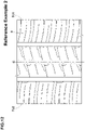
- a reference example (Ref. 1) as illustrated in FIG. 11 , a tyre having the first shoulder land portion (e) provided with lateral grooves (f) which extend from the first tread edge Te1 and terminate within the first shoulder land portion (e) was also manufactured by way of trial. Except for the above-mentioned items, the tread pattern of the tyre of reference example 1 is substantially the same as the tread pattern shown in FIG. 1 .
- steering stability on dry road and on-snow performance of each test tyre was tested. The common specification and test procedures are as described above. Note that in Table 2, the steering stability on dry road and on-snow performance are evaluated using a score where Ref. 1 is set to 100.
- Table 2 shows the test results. [Table 2] Ref. 1 Ex. 10 Ex. 11 Ex. 12 Ex. 13 Ex. 14 Ex. 15 Ex. 16 Ex. 17 Ex. 18 Tread pattern FIG. 11 FIG. 1 FIG. 1 FIG. 1 FIG. 1 FIG. 1 FIG. 1 FIG. 1 FIG. 1 FIG. 1 FIG. 1 FIG. 1 FIG. 1 FIG. 1 FIG. 1 FIG. 1 FIG. 1 FIG. 1 FIG. 1 FIG. 1 FIG. 1 FIG. 1 FIG. 1
- Tyres 165/65R14 having a basic tread pattern shown in FIG. 1 were manufactured by way of trial based on the detail shown in Table 3.
- a reference example 2 (Ref. 2), as illustrated in FIG. 12 , a tyre having the first shoulder land portion (g) which is not provided with chamfered portion was also manufactured by way of trial. Except for the above-mentioned items, the tread pattern of the tyre of reference example 2 is substantially the same as the tread pattern shown in FIG. 1 .
- steering stability on dry road and on-snow performance of each test tyre was tested. The common specification and test procedures are as described above. Note that in Table 3, the steering stability on dry road and on-snow performance are evaluated using a score where the Ref. 2 is set to 100.
- Table 2 shows the test results. [Table 3] Ref. 2 Ex. 19 Ex. 20 Ex. 21 Ex. 22 Ex. 23 Ex. 24 Ex. 25 Ex. 26 Tread pattern FIG. 12 FIG. 1 FIG. 1 FIG. 1 FIG. 1 FIG. 1 FIG. 1 FIG. 1 FIG. 1 FIG. 1 FIG. 1 FIG. 1 FIG. 1 FIG. 1 FIG. 1 FIG. 1 FIG. 1 FIG. 1 FIG. 1 FIG. 1 FIG. 1 FIG. 1 FIG. 1 FIG.
Description
- The present invention relates to tyres, more particularly to a tyre including a tread portion having a designated mounting direction to a vehicle.
- Conventionally, various tyres which include a tread portion having a mounting direction to a vehicle have been proposed (referring to the following patent document 1).
- [Patent document 1]
Japanese Unexamined Patent Application Publication 2015-140047 -
EP 2 151 333 A1 -
EP 3 318421 A1 -
JP 2013 018309 A - In tyres which are supposed to be used on both dry and snowy road conditions, lateral grooves provided on tread portions are helpful to improve on-snow performance, but provide low tread pattern stiffness, resulting in deteriorating steering stability on dry road condition. The inventors, through various experiments, have solved the above problem in tyres including a tread portion having a designated mounting direction to a vehicle by modifying layout of lateral grooves.
- The present invention has been made in view of the above problem and has a major object to provide tyres capable of improving steering stability on dry road conditions as well as on-snow performance.
- According to one aspect of the invention, a tyre includes a tread portion having a designated mounting direction to a vehicle. The tread portion includes a first tread edge located inwardly of a vehicle when being mounted to the vehicle, a second tread edge located outwardly of a vehicle when being mounted to the vehicle, circumferentially and continuously extending main grooves arranged between the first tread edge and the second tread edge, the main grooves including a first shoulder main groove arranged between the first tread edge and a tyre equator, a second shoulder main groove arranged between the second tread edge and the tyre equator, and at least one crown main groove arranged between the first shoulder main groove and the second shoulder main groove, and land portions divided by the main grooves, the land portions including a first middle land portion defined between the first shoulder main groove and the at least one crown main groove, a second middle land portion defined between the second shoulder main groove and the at least one crown main groove, a first shoulder land portion defined between the first shoulder main groove and the first tread edge, and a second shoulder land portion defined between the second shoulder main groove and the second tread edge. The first middle land portion is provided with first middle lateral grooves extending from the first shoulder main groove and terminating within the first middle land portion. The second middle land portion is provided with second middle lateral grooves extending from the at least one crown main groove and terminating within the second middle land portion. The first shoulder land portion is provided with first shoulder lateral grooves extending in a tyre axial direction. The second shoulder land portion is provided with second shoulder lateral grooves extending in the tyre axial direction. The first middle lateral grooves and the second middle lateral grooves are inclined in a first direction with respect to the tyre axial direction. The first shoulder lateral grooves and the second shoulder lateral grooves are inclined in a second direction opposite to the first direction with respect to the tyre axial direction. The tread portion is configured as a four-rib pattern which has four land portions and three main grooves.
- According to the invention, lengths in the tyre axial direction of the second middle lateral grooves are smaller than lengths in the tyre axial direction of the first middle lateral grooves.
- In another aspect of the present invention, lengths in the tyre axial direction of the first middle lateral grooves may be in a range of from 0.70 to 0.90 times a width in the tyre axial direction of the first middle land portion.
- In another aspect of the present invention, lengths in the tyre axial direction of the second middle lateral grooves may be in a range of from 0.40 to 0.60 times a width in the tyre axial direction of the second middle land portion.
- In another aspect of the present invention, a width in the tyre axial direction of the first shoulder land portion may be in a range of from 1.10 to 1.40 times a width in the tyre axial direction of the first middle land portion.
- In another aspect of the present invention, the first middle lateral grooves, the second middle lateral grooves, the first shoulder lateral grooves and the second shoulder lateral grooves may be inclined at angles equal to or less than 45 degrees with respect to the tyre axial direction.
- In another aspect of the present invention, the first middle land portion may not be provided with any grooves that are in communication with the at least one crown main groove directly and that have groove widths equal to or more than 1.5 mm.
- In another aspect of the present invention, the second middle land portion may not be provided with any grooves that are in communication with the second shoulder main groove directly and that have groove widths equal to or more than 1.5 mm.
- In another aspect of the present invention, the first shoulder lateral grooves may traverse the first shoulder land portion completely, and the second shoulder lateral grooves may traverse the second shoulder land portion completely.
- In another aspect of the present invention, the second middle land portion may be provided with semi-open middle sipes extending from the at least one crown main groove and terminating within the second middle land portion.
- In another aspect of the present invention, the first middle land portion may be provided with open middle sipes extending from the first shoulder main groove to the at least one crown main groove.
- In another aspect of the present invention, the first shoulder land portion may be provided with first shoulder sipes extending outwardly in the tyre axial direction from the first shoulder main groove.
- In another aspect of the present invention, the second shoulder land portion may be provided with second shoulder sipes having both ends terminating within the second shoulder land portion.
- In another aspect of the present invention, stiffness in the tyre circumferential direction of the second middle land portion may be greater than stiffness in the tyre circumferential direction of the first middle land portion.
- In another aspect of the present invention, stiffness in the tyre circumferential direction of the second shoulder land portion may be greater than stiffness in the tyre circumferential direction of the first shoulder land portion.
- In another aspect of the present invention, the first middle land portion may be provided with first middle chamfered portions which are recessed on a corner portion between a ground contact surface of the first middle land portion and a land sidewall on the first shoulder main groove side, the first middle chamfered portions may be connected to the respective first middle lateral grooves, the first shoulder lateral grooves may extend from the first shoulder main groove, the first shoulder land portion may be provided with first shoulder chamfered portions which are recessed on a corner portion between a ground contact surface of the first shoulder land portion and a land sidewall on the first shoulder main groove side, the first shoulder chamfered portions may be connected to the respective first shoulder lateral grooves, and at least one of the first middle chamfered portions, at least partially, may face either one of the first shoulder chamfered portions in the tyre axial direction.
- In another aspect of the present invention, the first middle chamfered portions may be connected to the respective first middle lateral grooves on a first side in the tyre circumferential direction, and the first shoulder chamfered portions may be connected to the first shoulder lateral grooves on a second side in the tyre circumferential direction.
- In another aspect of the present invention, a maximum angle of the first middle lateral grooves with respect to the tyre axial direction may be greater than a maximum angle of the first shoulder lateral grooves with respect to the tyre axial direction.
- In another aspect of the present invention, the first middle chamfered portions may include primary first middle chamfered portions which face the first shoulder chamfered portions and secondary first middle chamfered portions which do not face the first shoulder chamfered portions, and the primary first middle chamfered portions and the second first middle chamfered portions may be arranged alternately in the tyre circumferential direction.
- In another aspect of the present invention, the first shoulder lateral grooves may include some first shoulder lateral grooves which are connected to the first shoulder chamfered portions and some first shoulder lateral grooves which are not connected to the first shoulder chamfered portions, and which are arranged alternately in the tyre circumferential direction.
-
-
FIG. 1 is a development view of a tread portion of a tyre in accordance with an embodiment of the present invention; -
FIG. 2 is an enlarged view of a first middle land portion and a second middle land portion ofFIG. 1 ; -
FIG. 3 is a cross-sectional view taken along line A-A ofFIG. 2 ; -
FIG. 4 is a cross-sectional view taken along line B-B ofFIG. 2 ; -
FIG. 5 is a cross-sectional view taken along line C-C ofFIG. 2 ; -
FIG. 6 is a cross-sectional view taken along line D-D ofFIG. 2 ; -
FIG. 7 is an enlarged view of a first shoulder land portion ofFIG. 1 ; -
FIG. 8 is a cross-sectional view taken along line E-E ofFIG. 7 ; -
FIG. 9 is an enlarged view of a second shoulder land portion ofFIG. 1 ; -
FIG. 10 is a development view of a tread portion of a tyre according to a comparative example; -
FIG. 11 is a development view of a tread portion of a tyre according to a reference example 1; and -
FIG. 12 is a development view of a tread portion of a tyre according to a reference example 2. - An embodiment of the present invention will be explained below with reference to the accompanying drawings.
FIG. 1 illustrates a development view of atread portion 2 of atyre 1 according to an embodiment of the present invention. Thetyre 1 according to the present embodiment, for example, is suitably embodied as a pneumatic tyre for passenger car. Note that the present invention is not limited to such an aspect but can be embodied as a pneumatic tyre for heavy-duty vehicle and a non-pneumatic tyre which is not inflated with a pressurized air. - As illustrated in
FIG. 1 , thetyre 1 according to the present invention includes thetread portion 2 having a designated mounting direction to a vehicle. Thetread portion 2 includes a first tread edge Te1 located inwardly of a vehicle when being mounted to the vehicle and a second tread edge Te2 located outwardly of a vehicle when being mounted to the vehicle. The mounting direction to a vehicle, for example, may be indicated using letters or a mark on a tyre sidewall portion (not illustrated). - When the
tyre 1 is a pneumatic tyre, the first tread edge Te1 and the second tread edge Te2 are defined as axially outermost edges of the ground contacting patch of thetread portion 2 which occurs under a normal state with a standard tyre load when the camber angle of the tyre is zero. As used herein, the normal state is such that the tyre is mounted on a standard wheel rim with a standard pressure but loaded with no tyre load. As used herein, unless otherwise noted, dimensions of respective portions of the tyre are values measured under the normal state. - The standard wheel rim is a wheel rim officially approved for each tyre by standards organizations on which the tyre is based, wherein the standard wheel rim is the "standard rim" specified in JATMA, the "Design Rim" in TRA, and the "Measuring Rim" in ETRTO, for example.
- The standard pressure is a standard pressure officially approved for each tyre by standards organizations on which the tyre is based, wherein the standard pressure is the "maximum air pressure" in JATMA, the maximum pressure given in the "Tire Load Limits at Various Cold Inflation Pressures" table in TRA, and the "Inflation Pressure" in ETRTO, for example.
- The standard tyre load is a tyre load officially approved for each tyre by standards organizations in which the tyre is based, wherein the standard tyre load is the "maximum load capacity" in JATMA, the maximum value given in the above-mentioned table in TRA, the "Load Capacity" in ETRTO, for example.
- The
tread portion 2 includes a plurality of continuously extendingmain grooves 3 in the tyre circumferential direction arranged between the first tread edge Te1 and the second tread edge Te2, and a plurality ofland portions 4 divided by themain grooves 3. - The
main grooves 3 include a first shouldermain groove 5 arranged between the first tread edge Te1 and the tyre equator C, a second shouldermain groove 6 arranged between the second tread edge Te2 and the tyre equator C, and at least one crownmain groove 7 arranged between the first shouldermain groove 5 and the second shouldermain groove 6. - It is preferable that distances L1 in the tyre axial direction from the tyre equator C to a respective one of groove centerlines of the first shoulder
main groove 5 and the second shouldermain groove 6, for example, are in a range of from 0.15 to 0.30 times the tread width TW. The tread width TW is an axial distance from the first tread edge Te1 to the second tread edge Te2 under the normal state. - As the at least one crown
main groove 7, a single crownmain groove 7 is arranged on the tyre equator C, for example. In another aspect, two crownmain grooves 7 may be provided such that the tyre equator C is located therebetween, for example. - The
main grooves 3 according to the present invention, for example, extend straight in parallel with the tyre circumferential direction. Alternatively, themain grooves 3, for example, extend in a wavy or zigzag manner. - It is preferable that groove widths Wa of the
main grooves 3, for example, are in a range of from 3.0% to 6.0% of the tread width TW. It is preferable that groove depths of themain grooves 3, for example, are in a range of from 5 to 10 mm for a pneumatic tyre for passenger car. - The
land portions 4 include a firstmiddle land portion 11, a secondmiddle land portion 12, a firstshoulder land portion 13, and a secondshoulder land portion 14. Thetread portion 2 according to the present embodiment is configured as a four-rib pattern which has fourland portions 4 and threemain grooves 3. In another aspect of the present invention, for example, thetread portion 2 may be configured as five land portions with two crownmain grooves 7. - The first
middle land portion 11 is defined between the first shouldermain groove 5 and the crownmain groove 7. The secondmiddle land portion 12 is defined between the second shouldermain groove 6 and the crownmain groove 7. The firstshoulder land portion 13 is defined between the first shouldermain groove 5 and the first tread edge Te1. The secondshoulder land portion 14 is defined between the second shouldermain groove 6 and the second tread edge Te2. -
FIG. 2 illustrates an enlarged view of the firstmiddle land portion 11 and the secondmiddle land portion 12. As illustrated inFIG. 2 , widths W1 and W2 in the tyre axial direction of the firstmiddle land portion 11 and the secondmiddle land portion 12, respectively, are preferably in a range of from 0.15 to 0.25 times the tread width TW. In the present embodiment, the width W1 is equal to the width W2. Note that the present invention is not limited to such an aspect. - The first
middle land portion 11 is provided with a plurality of first middlelateral grooves 16. The first middlelateral grooves 16 extend from the first shouldermain groove 5 and terminating within the firstmiddle land portion 11. The secondmiddle land portion 12 is provided with a plurality of second middlelateral grooves 17. The second middlelateral grooves 17 extend from the crownmain groove 7 and terminate within the secondmiddle land portion 12. - When driving on snow, the first middle
lateral grooves 16 and the second middlelateral grooves 17 can compress snow and then shear it to generate reaction force, improving on-snow performance. Further, since the first middlelateral grooves 16 and the second middlelateral grooves 17 terminate within the respective land portions, reduction in stiffness of the firstmiddle land portion 11 and the secondmiddle land portion 12 on the second tread edge Te2 side (outboard) can be suppressed. Thus, when cornering on dry road condition such that the center of ground contact surface shifts toward the second tread edge Te2, torsion deformation of the firstmiddle land portion 11 and the secondmiddle land portion 12 can be suppressed, generating large cornering power, thus resulting in superior steering stability. - As illustrated in
FIG. 1 , the firstshoulder land portion 13 is provided with a plurality of firstshoulder lateral grooves 18 extending in the tyre axial direction. The secondshoulder land portion 14 is provided with a plurality of secondshoulder lateral grooves 19 extending in the tyre axial direction. The firstshoulder lateral grooves 18 and the secondshoulder lateral grooves 19 can generate powerful snow shearing force, improving on-snow performance as with the first middlelateral grooves 16 and the second middlelateral grooves 17. - In the present invention, the first middle
lateral grooves 16 and the second middlelateral grooves 17 are inclined in a first direction with respect to the tyre axial direction. The firstshoulder lateral grooves 18 and the secondshoulder lateral grooves 19 are inclined in a second direction opposite to the first direction with respect to the tyre axial direction. This makes it possible to prevent thetread portion 2 from deforming in a specific direction easily, improving steering stability further. In addition, the middle lateral grooves and the shoulder lateral grooves, when driving on snow, can form snow columns with different directions, providing snow shearing force in various directions, resulting in improving on-snow performance further. - In some preferred embodiments, the first
shoulder lateral grooves 18 traverse the firstshoulder land portion 13 completely. Further, the secondshoulder lateral grooves 19 traverse the secondshoulder land portion 14 completely. Thus, the firstshoulder lateral grooves 18 and the secondshoulder lateral grooves 19, when driving on snow, can form laterally long snow columns, improving snow traction further. - The first middle
lateral grooves 16, the second middlelateral grooves 17, the firstshoulder lateral grooves 18 and the secondshoulder lateral grooves 19 are inclined at angles equal to or less than 45 degrees with respect to the tyre axial direction. Such a layout of grooves, when driving on snow, provides superior traction performance. Specifically, it is preferable that the first middlelateral grooves 16 and the second middlelateral grooves 17, for example, are inclined at an angle of from 10 to 20 degrees with respect to the tyre axial direction. It is preferable that the firstshoulder lateral grooves 18 and the secondshoulder lateral grooves 19 are inclined at an angle of from 5 to 15 degrees with respect to the tyre axial direction. - As illustrated in
FIG. 2 , the first middlelateral grooves 16, for example, extend so as to traverse the center location in the tyre axial direction of the firstmiddle land portion 11. Specifically, lengths L2 in the tyre axial direction of the first middlelateral grooves 16 are in a range of from 0.70 to 0.90 times the width W1 in the tyre axial direction of the firstmiddle land portion 11. Such first middlelateral grooves 16 can improve steering stability on dry and on-snow performance in a well-balanced manner. - The first middle
lateral grooves 16, for example, each include a narrow-width portion 16a having a terminal end within the firstmiddle land portion 11, and a wide-width portion 16b which is connected to the narrow-width portion 16a on the first shouldermain groove 5 side and having a greater width than that of the narrow-width portion 16a. A length in the tyre axial direction of the narrow-width portion 16a, for example, is preferably equal to or more than 0.50 times, more preferably of from 0.60 to 0.80 times the length L2 in the tyre axial direction of the first middlelateral groove 16. Such first middlelateral grooves 16 can improve on-snow performance while maintaining sufficient stiffness of the firstmiddle land portion 11. -
FIG. 3 illustrates a cross-sectional view of one of the first middlelateral grooves 16 taken along line A-A ofFIG. 2 . As illustrated inFIG. 3 , it is preferable that at least one of the first middlelateral grooves 16, for example, includes ashallow bottom portion 16c in which a bottom thereof raises outwardly. A depth d2 of theshallow bottom portion 16c, for example, is in a range of from 0.60 to 0.75 times the maximum depth d1 of the first middlelateral groove 16. Such ashallow bottom portion 16c, while maintaining sufficient groove volume, can suppress that the first middlelateral groove 16 opens excessively. - Note that to help understanding the structure of the
shallow bottom portion 16c, theshallow bottom portion 16c of one of the first middlelateral grooves 16 is colored inFIG. 2 . As illustrated inFIG. 2 , theshallow bottom portion 16c, for example, is provided in the wide-width portion 16b. In some preferred embodiments, theshallow bottom portion 16c is provided with a distance from the end of the first middlelateral grooves 16 on the first shouldermain groove 5 side. A length in the tyre axial direction of theshallow bottom portion 16c, for example, may be in a range of from 0.10 to 0.30 times the length L2 in the tyre axial direction of the first middlelateral groove 16. - The first
middle land portion 11 is further provided with a plurality of openmiddle sipes 23 extending from the first shouldermain groove 5 to the crownmain groove 7, and a plurality of first connectingsipes 21 extending from the terminal ends of the first middlelateral grooves 16 to the crownmain groove 7. As used herein, a "sipe" shall mean an incision having a width of less than 1.5 mm, more preferably 0.5 to 1.0 mm, for example. - The open
middle sipes 23 and the first middlelateral grooves 16, for example, are arranged alternately in the tyre circumferential direction. The openmiddle sipes 23, for example, are inclined in the same direction as the first middlelateral grooves 16 with respect to the tyre axial direction. An angle of the openmiddle sipes 23 with respect to the tyre axial direction, for example, is in a range of from 10 to 20 degrees. -
FIG. 4 illustrates a cross-sectional view of one of the openmiddle sipes 23 taken along line B-B ofFIG. 2 . As illustrated inFIG. 4 , some of the openmiddle sipes 23, for example, each include at least oneshallow bottom portion 25 in which a bottom thereof raises. Some of the openmiddle sipes 23 according to the present embodiment, for example, each include a first shallow-bottom sipe portion 25a provided on one end of the sipe on the first shouldermain groove 5 side, a second shallow-bottom sipe portion 25b provided on the other end of the sipe on the crownmain grooves 7 side, and a third shallow-bottom sipe portion 25c provided between the first shallow-bottom sipe portion 25a and the second shallow-bottom sipe portion 25b. - In the present embodiment, the depth of the third shallow-
bottom sipe portion 25c is greater than the depth of the first shallow-bottom sipe portion 25a and the depth of the second shallow-bottom sipe portion 25b. In such anopen middle sipe 23, since axially both ends thereof are difficult to open as compared with a center portion thereof upon receiving ground contact pressure, excessive deformation of the firstmiddle land portion 11 can be suppressed. - It is preferable that the maximum depth of the open
middle sipes 23, for example, is in a range 0.25 to 0.75 times the depth of the crownmain groove 7. Such anopen middle sipe 23 can improve steering stability on dry road conditions and on-snow performance in a well-balanced manner. - As illustrated in
FIG. 2 , the first connectingsipes 21, for example, are inclined in the same direction as the first middlelateral grooves 16. The first connectingsipes 21 according to the present embodiment, for example, extend such that one sipe edge of the respective one of first connectingsipe 21 is continuous to one groove edge of the respective one of first middlelateral grooves 16 smoothly. - The first
middle land portion 11 is provided with first middle chamferedportions 26 which are recessed on a corner portion between the ground contact surface of the firstmiddle land portion 11 and a land sidewall thereof on the first shouldermain groove 5 side. The first middle chamferedportions 26 are connected to the respective first middlelateral grooves 16. In some preferred embodiments, the respective first middlelateral grooves 16 are connected to the respective first middle chamferedportions 26. In addition, the first middle chamferedportions 26 are connected to the first middlelateral grooves 16 on a first side in the tyre circumferential direction (below inFIG. 2 ). - In a plan view of the
tread portion 2, each first middle chamferedportions 26 according to the present embodiment is provided on an acute angle portion where an angle between the first shouldermain groove 5 and a respective one of first middlelateral grooves 16 is an acute angle. In other words, the first middlelateral grooves 16 are inclined to the first side in the tyre circumferential direction from the first shouldermain groove 5 toward the crownmain groove 7, and the respective first middle chamferedportions 26 are connected to the respective first middlelateral grooves 16 on the first side in the tyre circumferential direction. -
FIG. 5 illustrates a cross-sectional view of one of the first middle chamferedportions 26 taken along line C-C ofFIG. 2 . As illustrated inFIG. 5 , the first middle chamferedportions 26 each include afirst surface 26a extending along the land sidewall of the firstmiddle land portion 11 and asecond surface 26b extending along the ground contact surface of the firstmiddle land portion 11. - It is preferable that the maximum depth d4 of the first middle chamfered
portions 26, for example, is in a range of from 0.60 to 0.80 times the depth d3 of the first shouldermain groove 5. The first middle chamferedportions 26 according to the present embodiment, for example, have the same depth as that of the first middlelateral grooves 16. The first middle chamferedportions 26 can be helpful to improve steering stability on dry road conditions and on-snow performance in a well-balanced manner. - As illustrated in
FIG. 2 , in the same viewpoint, it is preferable a width W3 in the tyre axial direction of each first middle chamferedportion 26, for example, is in a range of from 0.05 to 0.15 times the width W1 in the tyre axial direction of the firstmiddle land portion 11. It is preferable that lengths in the tyre circumferential direction of the first middle chamferedportions 26, for example, are in a range of from 1.5 to 2.5 times the groove widths of the first middlelateral grooves 16. - The first
middle land portion 11 is not provided with any grooves that are in communication with the crownmain groove 7 directly and that have groove widths equal to or more than 1.5 mm. In addition, the firstmiddle land portion 11, on the crownmain groove 7 side thereof, is not provided with any chamfer portions. Such a firstmiddle land portion 11 may have high stiffness on the second tread edge Te2 side thereof, improving steering stability further. - It is preferable that a length L3 in the tyre axial direction of each the second middle
lateral groove 17, for example, is smaller than the length L2 in the tyre axial direction of each first middlelateral groove 16. For example, the length L3 of each second middlelateral groove 17 may be in a range of from 0.40 to 0.60 times the width W2 in the tyre axial direction of the secondmiddle land portion 12. Thus, the secondmiddle land portion 12 tends to be difficult to deform as compared with the firstmiddle land portion 11. Such a combination of the firstmiddle land portion 11 and the secondmiddle land portion 12 may provide linear steering response when cornering on dry road conditions in which the center of the ground contact surface shifts to the second tread edge Te2 side. - In some preferred embodiments, the difference between a ratio L2/W1 and a ratio L3/W2, for example, is in a range of from 0.25 to 0.35, where the ratio L2/W1 is a ratio of the length L2 of each first middle
lateral groove 16 to the width W1 of the firstmiddle land portion 11, and the ratio L3/W2 is a ratio of the length L3 of each second middlelateral groove 17 to the width W2 of the second middle land portion. Thus, stiffness balance between the firstmiddle land portion 11 and the secondmiddle land portion 12 may be appropriate, improving steering stability on dry road conditions and on-snow performance as well as suppressing uneven wear on the respective land portions. - Each second middle
lateral groove 17, for example, includes a narrow-width portion 17a including a terminal end thereof within the secondmiddle land portion 12, and a wide-width portion 17b which is connected to the narrow-width portion 17a at the crownmain groove 7 side of the narrow-width portion 17b and which has a greater width than that of the narrow-width portion 17a. It is preferable that a length in the tyre axial direction of the narrow-width portion 17a, for example, is equal to or more than 0.40 times, more preferably in a range of from 0.45 to 0.60 times the length L3 in the tyre axial direction of the second middlelateral grooves 17. - It is preferable that each second middle
lateral groove 17, for example, has ashallow bottom portion 17c in which a bottom thereof raises. InFIG. 2 , theshallow bottom portion 17c of one of the second middlelateral grooves 17 is colored. The above-mentioned configuration of the shallow bottom portions of first middlelateral grooves 16 can be employed to theshallow bottom portions 17c of second middlelateral grooves 17. - The second
middle land portion 12 is provided with a plurality of semi-openmiddle sipes 24 extending from the crownmain groove 7 and terminating within the secondmiddle land portion 12, and a plurality of second connectingsipes 22 extending from the respective terminal ends of the second middlelateral grooves 17 to the second shouldermain groove 6. - For example, the semi-open
middle sipes 24 and the second middlelateral grooves 17 are arranged alternately in the tyre circumferential direction. The semi-openmiddle sipes 24, for example, are inclined in the same direction as the second middlelateral grooves 17 with respect to the tyre axial direction. An angle of the semi-openmiddle sipes 24 is preferably in a range of from 10 to 20 degrees with respect to the tyre axial direction, for example. - A length L4 in the tyre axial direction of each
semi-open middle sipe 24, for example, is greater than the length L3 in the tyre axial direction of the second middlelateral grooves 17. The semi-openmiddle sipes 24 according to the present embodiment traverse the center location in the tyre axial direction of the secondmiddle land portion 12. Specifically, the length L4 of eachsemi-open middle sipe 24 is in a range of from 0.50 to 0.90 times the width W2 in the tyre axial direction of the secondmiddle land portion 12. Such semi-openmiddle sipes 24 can be helpful to improve steering stability and on-snow performance in a well-balanced manner. -
FIG. 6 illustrates a cross-sectional view of one of the semi-openmiddle sipes 24 taken along line D-D ofFIG. 2 . As illustrated inFIG. 6 , the semi-openmiddle sipes 24, for example, each include a plurality of shallowbottom portions 25 in which respective bottoms thereof raise. Each semi-openmiddle sipe 24 according to the present embodiment, for example, includes a fourthshallow bottom portion 25d provided on the crownmain grooves 7 side and a fifthshallow bottom portion 25e provided between the fourthshallow bottom portion 25d and the terminal end of semi-openmiddle sipes 24. - In the present embodiment, a depth d6 of the fifth
shallow bottom portion 25e is greater than a depth d5 of the fourthshallow bottom portion 25d. Thus, the semi-openmiddle sipes 24 can suppress deformation of the secondmiddle land portion 12 effectively, helping to improve steering stability. - It is preferable that the maximum depths of semi-open
middle sipes 24, for example, is in a range of from 0.25 to 0.75 times the depth of the crownmain groove 7. - As illustrated in
FIG. 2 , the second connectingsipes 22, for example, are inclined in the same direction as the second middlelateral grooves 17. The second connectingsipes 22 according to the present embodiment, for example, extend such that the respective second connectingsipes 22 are continuous to the respective second middlelateral grooves 17 smoothly. In some preferred embodiments, the second connectingsipes 22 may extend such that one of a pair of sipe edges of a respective one of the second connectingsipes 22 is continuous to one of a pair of groove edges of a respective one of the second middlelateral grooves 17 smoothly. - The second
middle land portion 12 is provided with second middle chamferedportions 27 which are recessed on a corner portion between the ground contact surface of thesecond land portion 12 and a land sidewall on the crownmain groove 7 side. Each second middle chamferedportion 26 is connected to either one of the second middlelateral grooves 17. In some preferred embodiment, the second middlelateral grooves 17 are connected to the second middle chamferedportions 27. The second middle chamferedportions 27 are connected to the second middlelateral grooves 17 on the first side (below inFIG. 2 ) in the tyre circumferential direction. - As the configuration of the second middle chamfered
portions 27, the configuration of the above-mentioned first middle chamferedportions 26 can be employed, and thus the explanation thereof is omitted herein. - The second
middle land portion 12 according to the present embodiment is not provided with any grooves that are in communication with the second shouldermain groove 6 directly and that have groove widths equal to or more than 1.5 mm. In addition, the corner between the ground contact surface and the land sidewall of the secondmiddle land portion 12 on the second shouldermain groove 6 side is not provided with the above-mentioned chamfered portions. Such a secondmiddle land portion 12 has high stiffness on the second tread edge Te2 side, providing linear steering response. - In the present embodiment, by employing the above-mentioned configuration, stiffness in the tyre circumferential direction of the second
middle land portion 12 is greater than stiffness in the tyre circumferential direction of the firstmiddle land portion 11. This makes it possible to provide linear steering response when cornering on dry road conditions in which the center of the ground contact surface shifts to the second tread edge Te2 side. -
FIG. 7 illustrates an enlarged view of the firstshoulder land portion 13. As illustrated inFIG. 7 , it is preferable that a width W4 in the tyre axial direction of the firstshoulder land portion 13 is in a range of from 1.10 to 1.70 times, more preferably in a range of from 1.10 to 1.40 times the width W1 (shown inFIG. 2 ) in the tyre axial direction of the firstmiddle land portion 11. -
FIG. 8 illustrates a cross-sectional view of one of the firstshoulder lateral grooves 18 taken along line E-E ofFIG. 8 . As illustrated inFIG. 8 , it is preferable that the firstshoulder lateral grooves 18, for example, have first shouldershallow bottom portions 31 in which bottoms thereof raise. The first shouldershallow bottom portions 31 according to the present embodiment, for example, are provided on end portions of the firstshoulder lateral grooves 18 on the first shouldermain groove 5 side. Thus, the first shouldershallow bottom portions 31 can be helpful to improve steering stability. - To help understanding the configuration of the first shoulder
shallow bottom portions 31, one of them is colored inFIG. 7 . As illustrated inFIG. 7 , a width W5 in the tyre axial direction of each first shouldershallow bottom portion 31, for example, is in a range of from 0.10 to 0.20 times the width W4 in the tyre axial direction of the firstshoulder land portion 13. The first shouldershallow bottom portions 31 as such can improve stiffness of the firstshoulder land portion 13 while maintaining on-snow performance. - The first
shoulder land portion 13 is provided with first shoulder chamferedportions 28 which are recessed on a corner portion between the ground contact surface of the firstshoulder land portion 13 and a land sidewall on the first shouldermain groove 5 side. Each first shoulder chamferedportion 26 is connected to either one of the firstshoulder lateral grooves 18. The first shoulder chamferedportions 28 are connected to the firstshoulder lateral grooves 18 on the second side in the tyre circumferential direction (above inFIG. 7 ). - As the configuration of the first shoulder chamfered
portions 28, the configuration of the above-mentioned first middle chamferedportions 26 can be employed, and thus the explanation thereof is omitted herein. - It is preferable that at least one of the first middle chamfered
portions 26, at least partially, faces either one of the first shoulder chamferedportions 28 in the tyre axial direction. This structure makes it possible to enlarge a substantial opening width of the first shouldermain groove 5 partially. Thus, when driving on snow, the enlarged opening width portion can form a larger and harder snow column, resulting in generating powerful snow-shearing force. - It is preferable that a length L5 in the tyre circumferential direction from an end in the tyre circumferential direction of the first middle chamfered
portions 26 on the first side to an end in the tyre circumferential direction of the first shoulder chamferedportions 28 on the second side (hereinafter, referred to as an "overlapping length") is in a range of from 0.60 to 0.90 times a length L8 in the tyre circumferential direction of the first shoulder chamferedportion 28. Such an arrangement of the chamfered portions can be helpful to suppress uneven wear of the firstmiddle land portion 11 and the firstshoulder land portion 13. - Each first shoulder chamfered
portion 28 according to the present embodiment, in a plan view of thetread portion 2, is provided on an acute angle portion where an angle between the first shouldermain groove 5 and a respective one of firstshoulder lateral grooves 18 is an acute angle. In other words, the firstshoulder lateral grooves 18 are inclined to the first side in the tyre circumferential direction from the first shouldermain groove 5 toward the first tread edge Te1, and the respective first shoulder chamferedportions 28 are connected to the respective first shoulder lateral grooves 86 on the second side in the tyre circumferential direction. - It is preferable that the maximum angle of the first middle
lateral groove 16 with respect to the tyre axial direction is greater than the maximum angle of the firstshoulder lateral groove 18 with respect to the tyre axial direction. Such a layout of lateral grooves makes it possible that the first middlelateral groove 16 generates snow-shearing force in the tyre axial direction, thus improving cornering performance on snow. - The first
shoulder land portion 13 according to the present embodiment is provided with some firstshoulder lateral grooves 18 which are connected to the first shoulder chamferedportions 28 and some firstshoulder lateral grooves 18 which are not connected to the first shoulder chamferedportions 28, and which are arranged alternately in the tyre circumferential direction. In the present embodiment, the first middle chamferedportions 26 include primary first middle chamfered portions which face the first shoulder chamferedportions 28 and secondary first middle chamfered portions which do not face the first shoulder chamferedportions 28, and the primary first middle chamfered portions and the second first middle chamfered portions are arranged alternately in the tyre circumferential direction. Such a layout of chamfered portions makes it possible to suppress excessive reduction of a ground contact surface area of the firstshoulder land portion 13 by the first shoulder chamferedportions 28. - The first
shoulder land portion 13 according to the present embodiment, for example, is provided withfirst shoulder sipes 36 and firstshort sipes 38. - The
first shoulder sipes 36, for example, extend from the first shouldermain groove 5 outwardly in the tyre axial direction. Thefirst shoulder sipes 36 according to the present embodiment, for example, terminate within the firstshoulder land portion 13. Thefirst shoulder sipes 36 can generate friction force while maintaining sufficient stiffness of the firstshoulder land portion 13. - The
first shoulder sipes 36, for example, extend along the firstshoulder lateral grooves 18. In the present embodiment, thefirst shoulder sipes 36 extend in parallel with the firstshoulder lateral grooves 18. A lengths L6 in the tyre axial direction of thefirst shoulder sipes 36, for example, is in a range of from 0.55 to 0.75 times the width W4 in the tyre axial direction of the firstshoulder land portion 13. Further, the maximum depth of thefirst shoulder sipes 36, for example, is in a range of from 0.25 to 0.75 times the depth of the first shouldermain groove 5. - It is preferable that at least one of the
first shoulder sipes 36 is in communication with either one of the first shoulder chamferedportions 28. Thus, when driving on snow, snow compressed by the first shoulder chamferedportions 28 can be discharged easily when the at least one of thefirst shoulder sipes 36 opens, exerting superior on-snow performance in a long period. - The first
short sipes 38, for example, extend from the first tread edge Te1 and terminating within the firstshoulder land portion 13. The respective firstshort sipes 38 according to the present embodiment, for example, are on extension lines of the respectivefirst shoulder sipes 36. In the present embodiment, gaps having lengths of from 1 to 10 mm are formed between thefirst shoulder sipes 36 and the firstshort sipes 38. Such firstshort sipes 38 generate friction force in cooperation with thefirst shoulder sipes 36 while maintaining sufficient stiffness of the firstshoulder land portion 13. -
FIG. 9 illustrates an enlarged view of the secondshoulder land portion 14. As illustrated inFIG. 9 , a width W6 in the tyre axial direction of the secondshoulder land portion 14 is preferably in a range of from 1.10 to 1.70 times, more preferably from 1.10 to 1.40 times the width W2 (shown inFIG. 2 ) in the tyre axial direction of the secondmiddle land portion 12. In the present embodiment, the firstshoulder land portion 13 and the secondshoulder land portion 14 are formed in the same width with one another. - It is preferable that one or more second
shoulder lateral grooves 19, for example, are provided with a second shouldershallow bottom portion 32 in which a bottom thereof raises. The second shouldershallow bottom portion 32, except the items which will be described below, has the substantially same configuration as the first shouldershallow bottom portions 31. Thus, the second shouldershallow bottom portion 32 can be employed the configuration of the first shouldershallow bottom portions 31. - In
FIG. 9 , to help understanding the configuration of the second shouldershallow bottom portion 32, the second shouldershallow bottom portion 32 of one of the secondshoulder lateral grooves 19 is colored. The second shouldershallow bottom portion 32, for example, is provided on an end of the secondshoulder lateral grooves 19 on the second shouldermain groove 6 side. - It is preferable that a width W7 in the tyre axial direction of the second shoulder
shallow bottom portion 32, for example, is greater than the width W5 in the tyre axial direction of the first shouldershallow bottom portions 31. Specifically, the width W7 of the second shouldershallow bottom portion 32 is in a range of from 1.5 to 2.5 times the width W5 of the first shouldershallow bottom portions 31. Such a second shouldershallow bottom portion 32 can improve stiffness of the secondshoulder land portion 14, enabling to exert superior steering stability. - The second
shoulder land portion 14 is provided with second shoulder chamferedportions 29 which are recessed on a corner portion between a ground contact surface of the secondshoulder land portion 14 and a land sidewall on the second shouldermain groove 6 side. The second shoulder chamferedportions 29 are connected to the respective secondshoulder lateral grooves 19. The second shoulder chamferedportions 29 are connected to the respective secondshoulder lateral grooves 19 on the first side in the tyre circumferential direction (below inFIG. 9 ). Such second shoulder chamferedportions 29, when driving on snow, can provide snow-shearing force in cooperation with the second shouldermain groove 6. - The second shoulder chamfered
portions 29 have the same cross-section as the first middle chamferedportions 26, and thus the explanation thereof is omitted herein. - The second
shoulder lateral grooves 19 includes some second shoulder lateral grooves which are connected to the second shoulder chamferedportions 29 and some second shoulder lateral grooves which are not connected to the second shoulder chamferedportions 29, and which are arranged alternately in the tyre circumferential direction. This makes it possible to suppress excessive reduction of a ground contact surface area of the secondshoulder land portion 14 due to the second shoulder chamferedportions 29. - The second
shoulder land portion 14 according to the present embodiment, for example, is provided with a plurality ofsecond shoulder sipes 37 and a plurality of the secondshort sipes 39. - The
second shoulder sipes 37, for example, each have both ends that are terminated within the secondshoulder land portion 14. It is preferable that the minimum distance from the second shouldermain groove 6 to the respectivesecond shoulder sipes 37, for example, is in a range of from 2 to 20 mm. Preferably, a length L7 in the tyre axial direction of thesecond shoulder sipes 37, for example, is in a range of from 0.50 to 0.70 times the width W6 in the tyre axial direction of the secondshoulder land portion 14. Preferably, the maximum depth of thesecond shoulder sipes 37, for example, is in a range of from 0.25 to 0.75 times the depth of the second shouldermain groove 6. - The second
short sipes 39, for example, extend from the second tread edge Te2 and terminate within the secondshoulder land portion 14. The secondshort sipes 39, for example, are provided on extension lines of the respectivesecond shoulder sipes 37. In the present embodiment, gaps of from 1 to 10 mm are formed between thesecond shoulder sipes 37 and the secondshort sipes 39. - In the present embodiment, by employing the above-mentioned structure, stiffness in the tyre circumferential direction of the second
shoulder land portion 14 is greater than stiffness in the tyre circumferential direction of the firstshoulder land portion 13. Thus, this may provide linear steering response when cornering on dry road condition such that the center of ground contact surface shifts toward the second tread edge Te2. On the contrary, when stiffness in the tyre circumferential direction of the firstshoulder land portion 13 is greater than stiffness in the tyre circumferential direction of the secondshoulder land portion 14, the tyre may generate less self-aligning torque, deteriorating steering response and steering stability. - While the particularly preferable embodiments in accordance with the present invention have been described in detail, the present invention is not limited to the illustrated embodiments, but can be modified and carried out in various aspects within the scope of the appended claims.
- Tyres 165/65R14 having a basic tread pattern shown in
FIG. 1 were manufactured by way of trial based on the detail shown in Table 1. As a comparative example, as illustrated inFIG. 10 , a tyre having a tread pattern in which the first shoulder lateral grooves (a) and the second shoulder lateral grooves (b) are inclined in the same direction as the first middle lateral grooves (c) and the second middle lateral grooves (d) was also manufactured by way of trial. Except for the above-mentioned items, the tread pattern of the comparative example is substantially the same as the tread pattern shown inFIG. 1 . Then, steering stability on dry road and on-snow performance of each test tyre was tested. The common specification and test procedures are as follows. - Rim size: 14x4.5J
- Tyre inner pressure: front 240kPa, rear 240kPa
- Test vehicle: front wheel drive car with displacement of 1300cc
- Test tyre location: all wheels
- Steering stability on dry road test:
A test driver drove the test vehicle on dry road and then evaluated steering stability of the test tyres by the driver's feeling. The test results are shown in Table 1 using a score where Ref. is set to 100. The larger the value, the better the steering stability on dry road is. - On-snow performance test:
A test driver drove the test vehicle on snowy road and then evaluated snow traction, braking performance, and cornering performance of the test tyres by the driver's feeling. The test results are shown in Table 1 using a score where Ref. is set to 100. The larger the value, the better the on-snow performance is. - Table 1 shows the test results.
[Table 1] Ref. Ex. 1 Ex. 2 Ex. 3 Ex. 4 Ex. 5 Ex. 6 Ex. 7 Ex. 8 Ex. 9 Tread pattern FIG. 10 FIG. 1 FIG. 1 FIG. 1 FIG. 1 FIG. 1 FIG. 1 FIG. 1 FIG. 1 FIG. 1 Length L2 of first middle lateral grooves / width W1 of first middle land portion 0.77 0.77 0.70 0.75 0.85 0.90 0.77 0.77 0.77 0.77 Lengths L3 of second middle lateral grooves width W2 of second middle land portion 0.48 0.48 0.48 0.48 0.48 0.48 0.40 0.45 0.55 0.60 Steering stability on dry road (score) 100 106 107 106 104 103 106 106 104 103 On-snow performance (score) 100 107 104 106 106 107 106 107 107 107 - From the test results, it is confirmed that the tyres of examples improve steering stability on dry road and on-snow performance.
- Tyres 165/65R14 having a basic tread pattern shown in
FIG. 1 were manufactured by way of trial based on the detail shown in Table 2. As a reference example (Ref. 1), as illustrated inFIG. 11 , a tyre having the first shoulder land portion (e) provided with lateral grooves (f) which extend from the first tread edge Te1 and terminate within the first shoulder land portion (e) was also manufactured by way of trial. Except for the above-mentioned items, the tread pattern of the tyre of reference example 1 is substantially the same as the tread pattern shown inFIG. 1 . Then, steering stability on dry road and on-snow performance of each test tyre was tested. The common specification and test procedures are as described above. Note that in Table 2, the steering stability on dry road and on-snow performance are evaluated using a score where Ref. 1 is set to 100. - Table 2 shows the test results.
[Table 2] Ref. 1 Ex. 10 Ex. 11 Ex. 12 Ex. 13 Ex. 14 Ex. 15 Ex. 16 Ex. 17 Ex. 18 Tread pattern FIG. 11 FIG. 1 FIG. 1 FIG. 1 FIG. 1 FIG. 1 FIG. 1 FIG. 1 FIG. 1 FIG. 1 Lengths L2 of first middle lateral grooves / width W1 of first middle land portion 0.77 0.77 0.70 0.75 0.85 0.90 0.77 0.77 0.77 0.77 Length L3 of second middle lateral grooves / width W2 of second middle land portion 0.48 0.48 0.48 0.48 0.48 0.48 0.40 0.45 0.55 0.60 Steering stability on dry road (score) 100 103 103 103 102 101 105 104 102 101 On-snow performance (score) 100 106 104 106 106 107 104 105 106 106 - From the test results, it is confirmed that the tyres of examples improve steering stability on dry road and on-snow performance.
- Tyres 165/65R14 having a basic tread pattern shown in
FIG. 1 were manufactured by way of trial based on the detail shown in Table 3. As a reference example 2 (Ref. 2), as illustrated inFIG. 12 , a tyre having the first shoulder land portion (g) which is not provided with chamfered portion was also manufactured by way of trial. Except for the above-mentioned items, the tread pattern of the tyre of reference example 2 is substantially the same as the tread pattern shown inFIG. 1 . Then, steering stability on dry road and on-snow performance of each test tyre was tested. The common specification and test procedures are as described above. Note that in Table 3, the steering stability on dry road and on-snow performance are evaluated using a score where the Ref. 2 is set to 100. - Table 2 shows the test results.
[Table 3] Ref. 2 Ex. 19 Ex. 20 Ex. 21 Ex. 22 Ex. 23 Ex. 24 Ex. 25 Ex. 26 Tread pattern FIG. 12 FIG. 1 FIG. 1 FIG. 1 FIG. 1 FIG. 1 FIG. 1 FIG. 1 FIG. 1 Overlapping length L5 / length L8 of first shoulder chamfered portions - 0.68 0.60 0.65 0.75 0.80 0.90 0.68 0.68 Widths W3 of first middle chamfered portions / width W1 of first middle land portion 0.09 0.09 0.09 0.09 0.09 0.09 0.09 0.05 0.15 Steering stability on dry road (score) 100 102 102 102 102 101 101 102 101 On-snow performance (score) 100 108 106 107 108 108 108 106 108 - From the test results, it is confirmed that the tyres of the examples improve the steering stability on dry road and on-snow performance.
Claims (13)
- A tyre (1) comprising
a tread portion (2) having a designated mounting direction to a vehicle, the tread portion (2) comprising:a first tread edge (Te1) located inwardly of a vehicle when being mounted to the vehicle;a second tread edge (Te2) located outwardly of a vehicle when being mounted to the vehicle;circumferentially and continuously extending main grooves (3) arranged between the first tread edge (Te1) and the second tread edge (Te2), the main grooves (3) comprising a first shoulder main groove (5) arranged between the first tread edge (Te1) and a tyre equator (C), a second shoulder main groove (6) arranged between the second tread edge (Te2) and the tyre equator (C), and at least one crown main groove (7) arranged between the first shoulder main groove (5) and the second shoulder main groove (6); andland portions (4) divided by the main grooves (3), the land portions (4) comprising a first middle land portion (11) defined between the first shoulder main groove (5) and the at least one crown main groove (7), a second middle land portion (12) defined between the second shoulder main groove (6) and the at least one crown main groove (7), a first shoulder land portion (13) defined between the first shoulder main groove (5) and the first tread edge (Te1), and a second shoulder land portion (14) defined between the second shoulder main groove (6) and the second tread edge (Te2),wherein the first middle land portion (11) is provided with first middle lateral grooves (16) extending from the first shoulder main groove (5) and terminating within the first middle land portion (11),wherein the second middle land portion (12) is provided with second middle lateral grooves (17) extending from the at least one crown main groove (7) and terminating within the second middle land portion (12),wherein the first shoulder land portion (13) is provided with first shoulder lateral grooves (18) extending in a tyre axial direction,wherein the second shoulder land portion (14) is provided with second shoulder lateral grooves (19) extending in the tyre axial direction,wherein the first middle lateral grooves (16) and the second middle lateral grooves (17) are inclined in a first direction with respect to the tyre axial direction, andwherein the first shoulder lateral grooves (18) and the second shoulder lateral grooves (19) are inclined in a second direction opposite to the first direction with respect to the tyre axial direction,wherein the tread portion (2) is configured as a four-rib pattern which has four land portions (4) and three main grooves (3),
characterized in that
lengths (L3) in the tyre axial direction of the second middle lateral grooves (17) are smaller than lengths (L2) in the tyre axial direction of the first middle lateral grooves (16). - The tyre according to claim 1,
wherein lengths (L2) in the tyre axial direction of the first middle lateral grooves (16) are in a range of from 0.70 to 0.90 times a width in the tyre axial direction of the first middle land portion(11). - The tyre according to claim 1 or 2,
wherein the first middle lateral grooves (16), the second middle lateral grooves (17), the first shoulder lateral grooves (18) and the second shoulder lateral grooves (19) are inclined at angles equal to or less than 45 degrees with respect to the tyre axial direction. - The tyre according to any one of claims 1 to 3,
wherein the first middle land portion (11) is not provided with any grooves that are in communication with the at least one crown main groove (7) directly and that have groove widths equal to or more than 1.5 mm. - The tyre according to any one of claims 1 to 4,wherein the first shoulder lateral grooves (18) traverse the first shoulder land portion (13) completely, andwherein the second shoulder lateral grooves (19) traverse the second shoulder land portion (14) completely.
- The tyre according to any one of claims 1 to 5,
wherein the second middle land portion (12) is provided with semi-open middle sipes (24) extending from the at least one crown main groove (7) and terminating within the second middle land portion (12). - The tyre according to any one of claims 1 to 6,
wherein the first middle land portion (11) is provided with open middle sipes (23) extending from the first shoulder main groove (5) to the at least one crown main groove (7). - The tyre according to any one of claims 1 to 7,
wherein the first shoulder land portion (13) is provided with first shoulder sipes (36) extending outwardly in the tyre axial direction from the first shoulder main groove (5). - The tyre according to any one of claims 1 to 8,wherein the first middle land portion (11) is provided with first middle chamfered portions (26) which are recessed on a corner portion between a ground contact surface of the first middle land portion (11) and a land sidewall on the first shoulder main groove side,wherein the first middle chamfered portions (26) are connected to the respective first middle lateral grooves (16),wherein the first shoulder lateral grooves (18) extend from the first shoulder main groove (5),wherein the first shoulder land portion (13) is provided with first shoulder chamfered portions (28) which are recessed on a corner portion between a ground contact surface of the first shoulder land portion (13) and a land sidewall on the first shoulder main groove side, wherein the first shoulder chamfered portions (28) are connected to the respective first shoulder lateral grooves (18), andwherein at least one of the first middle chamfered portions (26), at least partially, faces either one of the first shoulder chamfered portions (28) in the tyre axial direction.
- The tyre according to claim 9,wherein the first middle chamfered portions (26) are connected to the respective first middle lateral grooves (16) on a first side in the tyre circumferential direction, andwherein the first shoulder chamfered portions (28) are connected to the first shoulder lateral grooves (18) on a second side in the tyre circumferential direction.
- The tyre according to claim 9 or 10,
wherein a maximum angle of the first middle lateral grooves (16) with respect to the tyre axial direction is greater than a maximum angle of the first shoulder lateral grooves (18) with respect to the tyre axial direction. - The tyre according to any one of claims 9 to 11,wherein the first middle chamfered portions (26) comprise primary first middle chamfered portions which face the first shoulder chamfered portions (28) and secondary first middle chamfered portions which do not face the first shoulder chamfered portions (28), andwherein the primary first middle chamfered portions and the second first middle chamfered portions are arranged alternately in the tyre circumferential direction.
- The tyre according to claim any one of claims 9 to 12,
wherein the first shoulder lateral grooves (18) comprise some first shoulder lateral grooves which are connected to the first shoulder chamfered portions (28) and some first shoulder lateral grooves which are not connected to the first shoulder chamfered portions (28), and which are arranged alternately in the tyre circumferential direction.
Applications Claiming Priority (3)
| Application Number | Priority Date | Filing Date | Title |
|---|---|---|---|
| JP2018193643A JP7139860B2 (en) | 2018-10-12 | 2018-10-12 | tire |
| JP2018193642A JP7183681B2 (en) | 2018-10-12 | 2018-10-12 | tire |
| JP2018193641A JP7131284B2 (en) | 2018-10-12 | 2018-10-12 | tire |
Publications (2)
| Publication Number | Publication Date |
|---|---|
| EP3636459A1 EP3636459A1 (en) | 2020-04-15 |
| EP3636459B1 true EP3636459B1 (en) | 2022-04-06 |
Family
ID=67981949
Family Applications (1)
| Application Number | Title | Priority Date | Filing Date |
|---|---|---|---|
| EP19197535.8A Active EP3636459B1 (en) | 2018-10-12 | 2019-09-16 | Tyre |
Country Status (3)
| Country | Link |
|---|---|
| US (1) | US11446963B2 (en) |
| EP (1) | EP3636459B1 (en) |
| CN (1) | CN111038179B (en) |
Families Citing this family (2)
| Publication number | Priority date | Publication date | Assignee | Title |
|---|---|---|---|---|
| JP2022080119A (en) * | 2020-11-17 | 2022-05-27 | 住友ゴム工業株式会社 | tire |
| JP2022104139A (en) * | 2020-12-28 | 2022-07-08 | Toyo Tire株式会社 | Pneumatic tire |
Family Cites Families (16)
| Publication number | Priority date | Publication date | Assignee | Title |
|---|---|---|---|---|
| JP5131248B2 (en) * | 2008-08-05 | 2013-01-30 | 横浜ゴム株式会社 | Pneumatic tire |
| JP4685919B2 (en) * | 2008-12-08 | 2011-05-18 | 住友ゴム工業株式会社 | Pneumatic tire |
| JP4697336B2 (en) * | 2009-02-20 | 2011-06-08 | 横浜ゴム株式会社 | Pneumatic tire |
| JP5905673B2 (en) | 2011-07-07 | 2016-04-20 | 株式会社ブリヂストン | tire |
| JP2015030414A (en) * | 2013-08-05 | 2015-02-16 | 住友ゴム工業株式会社 | Pneumatic tire |
| JP6420547B2 (en) | 2014-01-27 | 2018-11-07 | 住友ゴム工業株式会社 | Pneumatic tire |
| JP6047123B2 (en) * | 2014-07-03 | 2016-12-21 | 住友ゴム工業株式会社 | Pneumatic tire |
| JP6405284B2 (en) * | 2015-04-17 | 2018-10-17 | 住友ゴム工業株式会社 | Pneumatic tire |
| JP6582726B2 (en) * | 2015-08-20 | 2019-10-02 | 住友ゴム工業株式会社 | tire |
| JP6555040B2 (en) * | 2015-09-16 | 2019-08-07 | 住友ゴム工業株式会社 | tire |
| JP6623764B2 (en) * | 2016-01-06 | 2019-12-25 | 住友ゴム工業株式会社 | Pneumatic tire |
| JP6668782B2 (en) * | 2016-01-26 | 2020-03-18 | 住友ゴム工業株式会社 | tire |
| JP6711169B2 (en) | 2016-06-24 | 2020-06-17 | 住友ゴム工業株式会社 | tire |
| JP6848359B2 (en) * | 2016-11-08 | 2021-03-24 | 住友ゴム工業株式会社 | tire |
| JP6828387B2 (en) * | 2016-11-14 | 2021-02-10 | 住友ゴム工業株式会社 | tire |
| JP2019093872A (en) * | 2017-11-22 | 2019-06-20 | Toyo Tire株式会社 | Pneumatic tire |
-
2019
- 2019-09-16 CN CN201910869627.3A patent/CN111038179B/en active Active
- 2019-09-16 US US16/571,317 patent/US11446963B2/en active Active
- 2019-09-16 EP EP19197535.8A patent/EP3636459B1/en active Active
Also Published As
| Publication number | Publication date |
|---|---|
| CN111038179B (en) | 2023-04-07 |
| CN111038179A (en) | 2020-04-21 |
| US20200114696A1 (en) | 2020-04-16 |
| EP3636459A1 (en) | 2020-04-15 |
| US11446963B2 (en) | 2022-09-20 |
Similar Documents
| Publication | Publication Date | Title |
|---|---|---|
| EP3260308B1 (en) | Tire | |
| EP3326840B1 (en) | Tire | |
| EP3153334B1 (en) | Tire | |
| EP3296127B1 (en) | Pneumatic tire | |
| EP3388257B1 (en) | Tire | |
| EP2664464B1 (en) | Pneumatic tire | |
| EP3421263B1 (en) | Tire | |
| EP3081393B1 (en) | Pneumatic tire | |
| EP3398793B1 (en) | Tire | |
| EP3248810B1 (en) | Tire | |
| EP3315326B1 (en) | Tire | |
| EP2465706A2 (en) | Pneumatic tire | |
| EP3560732A1 (en) | Tyre | |
| EP3575110B1 (en) | Tyre | |
| EP3549791B1 (en) | Tyre | |
| EP3564047A1 (en) | Tyre | |
| EP4173846A1 (en) | Tyre | |
| EP3828011B1 (en) | Tyre tread | |
| EP3636459B1 (en) | Tyre | |
| EP3546249B1 (en) | Tyre | |
| EP3822093A1 (en) | Tire | |
| EP3744536B1 (en) | Tyre | |
| EP3960504B1 (en) | Tire | |
| EP3970996B1 (en) | Tire | |
| EP3835087B1 (en) | Tire |
Legal Events
| Date | Code | Title | Description |
|---|---|---|---|
| PUAI | Public reference made under article 153(3) epc to a published international application that has entered the european phase |
Free format text: ORIGINAL CODE: 0009012 |
|
| STAA | Information on the status of an ep patent application or granted ep patent |
Free format text: STATUS: THE APPLICATION HAS BEEN PUBLISHED |
|
| AK | Designated contracting states |
Kind code of ref document: A1 Designated state(s): AL AT BE BG CH CY CZ DE DK EE ES FI FR GB GR HR HU IE IS IT LI LT LU LV MC MK MT NL NO PL PT RO RS SE SI SK SM TR |
|
| AX | Request for extension of the european patent |
Extension state: BA ME |
|
| STAA | Information on the status of an ep patent application or granted ep patent |
Free format text: STATUS: REQUEST FOR EXAMINATION WAS MADE |
|
| 17P | Request for examination filed |
Effective date: 20201009 |
|
| RBV | Designated contracting states (corrected) |
Designated state(s): AL AT BE BG CH CY CZ DE DK EE ES FI FR GB GR HR HU IE IS IT LI LT LU LV MC MK MT NL NO PL PT RO RS SE SI SK SM TR |
|
| STAA | Information on the status of an ep patent application or granted ep patent |
Free format text: STATUS: EXAMINATION IS IN PROGRESS |
|
| 17Q | First examination report despatched |
Effective date: 20210811 |
|
| GRAP | Despatch of communication of intention to grant a patent |
Free format text: ORIGINAL CODE: EPIDOSNIGR1 |
|
| STAA | Information on the status of an ep patent application or granted ep patent |
Free format text: STATUS: GRANT OF PATENT IS INTENDED |
|
| INTG | Intention to grant announced |
Effective date: 20211220 |
|
| GRAS | Grant fee paid |
Free format text: ORIGINAL CODE: EPIDOSNIGR3 |
|
| GRAA | (expected) grant |
Free format text: ORIGINAL CODE: 0009210 |
|
| STAA | Information on the status of an ep patent application or granted ep patent |
Free format text: STATUS: THE PATENT HAS BEEN GRANTED |
|
| AK | Designated contracting states |
Kind code of ref document: B1 Designated state(s): AL AT BE BG CH CY CZ DE DK EE ES FI FR GB GR HR HU IE IS IT LI LT LU LV MC MK MT NL NO PL PT RO RS SE SI SK SM TR |
|
| REG | Reference to a national code |
Ref country code: GB Ref legal event code: FG4D |
|
| REG | Reference to a national code |
Ref country code: CH Ref legal event code: EP |
|
| REG | Reference to a national code |
Ref country code: AT Ref legal event code: REF Ref document number: 1480997 Country of ref document: AT Kind code of ref document: T Effective date: 20220415 |
|
| REG | Reference to a national code |
Ref country code: DE Ref legal event code: R096 Ref document number: 602019013334 Country of ref document: DE |
|
| REG | Reference to a national code |
Ref country code: IE Ref legal event code: FG4D |
|
| REG | Reference to a national code |
Ref country code: LT Ref legal event code: MG9D |
|
| REG | Reference to a national code |
Ref country code: NL Ref legal event code: MP Effective date: 20220406 |
|
| REG | Reference to a national code |
Ref country code: AT Ref legal event code: MK05 Ref document number: 1480997 Country of ref document: AT Kind code of ref document: T Effective date: 20220406 |
|
| PG25 | Lapsed in a contracting state [announced via postgrant information from national office to epo] |
Ref country code: NL Free format text: LAPSE BECAUSE OF FAILURE TO SUBMIT A TRANSLATION OF THE DESCRIPTION OR TO PAY THE FEE WITHIN THE PRESCRIBED TIME-LIMIT Effective date: 20220406 |
|
| PG25 | Lapsed in a contracting state [announced via postgrant information from national office to epo] |
Ref country code: SE Free format text: LAPSE BECAUSE OF FAILURE TO SUBMIT A TRANSLATION OF THE DESCRIPTION OR TO PAY THE FEE WITHIN THE PRESCRIBED TIME-LIMIT Effective date: 20220406 Ref country code: PT Free format text: LAPSE BECAUSE OF FAILURE TO SUBMIT A TRANSLATION OF THE DESCRIPTION OR TO PAY THE FEE WITHIN THE PRESCRIBED TIME-LIMIT Effective date: 20220808 Ref country code: NO Free format text: LAPSE BECAUSE OF FAILURE TO SUBMIT A TRANSLATION OF THE DESCRIPTION OR TO PAY THE FEE WITHIN THE PRESCRIBED TIME-LIMIT Effective date: 20220706 Ref country code: LT Free format text: LAPSE BECAUSE OF FAILURE TO SUBMIT A TRANSLATION OF THE DESCRIPTION OR TO PAY THE FEE WITHIN THE PRESCRIBED TIME-LIMIT Effective date: 20220406 Ref country code: HR Free format text: LAPSE BECAUSE OF FAILURE TO SUBMIT A TRANSLATION OF THE DESCRIPTION OR TO PAY THE FEE WITHIN THE PRESCRIBED TIME-LIMIT Effective date: 20220406 Ref country code: GR Free format text: LAPSE BECAUSE OF FAILURE TO SUBMIT A TRANSLATION OF THE DESCRIPTION OR TO PAY THE FEE WITHIN THE PRESCRIBED TIME-LIMIT Effective date: 20220707 Ref country code: FI Free format text: LAPSE BECAUSE OF FAILURE TO SUBMIT A TRANSLATION OF THE DESCRIPTION OR TO PAY THE FEE WITHIN THE PRESCRIBED TIME-LIMIT Effective date: 20220406 Ref country code: ES Free format text: LAPSE BECAUSE OF FAILURE TO SUBMIT A TRANSLATION OF THE DESCRIPTION OR TO PAY THE FEE WITHIN THE PRESCRIBED TIME-LIMIT Effective date: 20220406 Ref country code: BG Free format text: LAPSE BECAUSE OF FAILURE TO SUBMIT A TRANSLATION OF THE DESCRIPTION OR TO PAY THE FEE WITHIN THE PRESCRIBED TIME-LIMIT Effective date: 20220706 Ref country code: AT Free format text: LAPSE BECAUSE OF FAILURE TO SUBMIT A TRANSLATION OF THE DESCRIPTION OR TO PAY THE FEE WITHIN THE PRESCRIBED TIME-LIMIT Effective date: 20220406 |
|
| PG25 | Lapsed in a contracting state [announced via postgrant information from national office to epo] |
Ref country code: RS Free format text: LAPSE BECAUSE OF FAILURE TO SUBMIT A TRANSLATION OF THE DESCRIPTION OR TO PAY THE FEE WITHIN THE PRESCRIBED TIME-LIMIT Effective date: 20220406 Ref country code: PL Free format text: LAPSE BECAUSE OF FAILURE TO SUBMIT A TRANSLATION OF THE DESCRIPTION OR TO PAY THE FEE WITHIN THE PRESCRIBED TIME-LIMIT Effective date: 20220406 Ref country code: LV Free format text: LAPSE BECAUSE OF FAILURE TO SUBMIT A TRANSLATION OF THE DESCRIPTION OR TO PAY THE FEE WITHIN THE PRESCRIBED TIME-LIMIT Effective date: 20220406 Ref country code: IS Free format text: LAPSE BECAUSE OF FAILURE TO SUBMIT A TRANSLATION OF THE DESCRIPTION OR TO PAY THE FEE WITHIN THE PRESCRIBED TIME-LIMIT Effective date: 20220806 |
|
| REG | Reference to a national code |
Ref country code: DE Ref legal event code: R097 Ref document number: 602019013334 Country of ref document: DE |
|
| PG25 | Lapsed in a contracting state [announced via postgrant information from national office to epo] |
Ref country code: SM Free format text: LAPSE BECAUSE OF FAILURE TO SUBMIT A TRANSLATION OF THE DESCRIPTION OR TO PAY THE FEE WITHIN THE PRESCRIBED TIME-LIMIT Effective date: 20220406 Ref country code: SK Free format text: LAPSE BECAUSE OF FAILURE TO SUBMIT A TRANSLATION OF THE DESCRIPTION OR TO PAY THE FEE WITHIN THE PRESCRIBED TIME-LIMIT Effective date: 20220406 Ref country code: RO Free format text: LAPSE BECAUSE OF FAILURE TO SUBMIT A TRANSLATION OF THE DESCRIPTION OR TO PAY THE FEE WITHIN THE PRESCRIBED TIME-LIMIT Effective date: 20220406 Ref country code: EE Free format text: LAPSE BECAUSE OF FAILURE TO SUBMIT A TRANSLATION OF THE DESCRIPTION OR TO PAY THE FEE WITHIN THE PRESCRIBED TIME-LIMIT Effective date: 20220406 Ref country code: DK Free format text: LAPSE BECAUSE OF FAILURE TO SUBMIT A TRANSLATION OF THE DESCRIPTION OR TO PAY THE FEE WITHIN THE PRESCRIBED TIME-LIMIT Effective date: 20220406 Ref country code: CZ Free format text: LAPSE BECAUSE OF FAILURE TO SUBMIT A TRANSLATION OF THE DESCRIPTION OR TO PAY THE FEE WITHIN THE PRESCRIBED TIME-LIMIT Effective date: 20220406 |
|
| PLBE | No opposition filed within time limit |
Free format text: ORIGINAL CODE: 0009261 |
|
| STAA | Information on the status of an ep patent application or granted ep patent |
Free format text: STATUS: NO OPPOSITION FILED WITHIN TIME LIMIT |
|
| 26N | No opposition filed |
Effective date: 20230110 |
|
| PG25 | Lapsed in a contracting state [announced via postgrant information from national office to epo] |
Ref country code: AL Free format text: LAPSE BECAUSE OF FAILURE TO SUBMIT A TRANSLATION OF THE DESCRIPTION OR TO PAY THE FEE WITHIN THE PRESCRIBED TIME-LIMIT Effective date: 20220406 |
|
| PG25 | Lapsed in a contracting state [announced via postgrant information from national office to epo] |
Ref country code: MC Free format text: LAPSE BECAUSE OF FAILURE TO SUBMIT A TRANSLATION OF THE DESCRIPTION OR TO PAY THE FEE WITHIN THE PRESCRIBED TIME-LIMIT Effective date: 20220406 |
|
| REG | Reference to a national code |
Ref country code: CH Ref legal event code: PL |
|
| REG | Reference to a national code |
Ref country code: BE Ref legal event code: MM Effective date: 20220930 |
|
| PG25 | Lapsed in a contracting state [announced via postgrant information from national office to epo] |
Ref country code: SI Free format text: LAPSE BECAUSE OF FAILURE TO SUBMIT A TRANSLATION OF THE DESCRIPTION OR TO PAY THE FEE WITHIN THE PRESCRIBED TIME-LIMIT Effective date: 20220406 |
|
| P01 | Opt-out of the competence of the unified patent court (upc) registered |
Effective date: 20230510 |
|
| PG25 | Lapsed in a contracting state [announced via postgrant information from national office to epo] |
Ref country code: LU Free format text: LAPSE BECAUSE OF NON-PAYMENT OF DUE FEES Effective date: 20220916 |
|
| PG25 | Lapsed in a contracting state [announced via postgrant information from national office to epo] |
Ref country code: LI Free format text: LAPSE BECAUSE OF NON-PAYMENT OF DUE FEES Effective date: 20220930 Ref country code: IE Free format text: LAPSE BECAUSE OF NON-PAYMENT OF DUE FEES Effective date: 20220916 Ref country code: CH Free format text: LAPSE BECAUSE OF NON-PAYMENT OF DUE FEES Effective date: 20220930 |
|
| PG25 | Lapsed in a contracting state [announced via postgrant information from national office to epo] |
Ref country code: BE Free format text: LAPSE BECAUSE OF NON-PAYMENT OF DUE FEES Effective date: 20220930 |
|
| PGFP | Annual fee paid to national office [announced via postgrant information from national office to epo] |
Ref country code: FR Payment date: 20230808 Year of fee payment: 5 Ref country code: DE Payment date: 20230802 Year of fee payment: 5 |
|
| PG25 | Lapsed in a contracting state [announced via postgrant information from national office to epo] |
Ref country code: IT Free format text: LAPSE BECAUSE OF FAILURE TO SUBMIT A TRANSLATION OF THE DESCRIPTION OR TO PAY THE FEE WITHIN THE PRESCRIBED TIME-LIMIT Effective date: 20220406 |
|
| PG25 | Lapsed in a contracting state [announced via postgrant information from national office to epo] |
Ref country code: HU Free format text: LAPSE BECAUSE OF FAILURE TO SUBMIT A TRANSLATION OF THE DESCRIPTION OR TO PAY THE FEE WITHIN THE PRESCRIBED TIME-LIMIT; INVALID AB INITIO Effective date: 20190916 |