EP3208090A2 - Printing apparatus and printing method - Google Patents
Printing apparatus and printing method Download PDFInfo
- Publication number
- EP3208090A2 EP3208090A2 EP17152748.4A EP17152748A EP3208090A2 EP 3208090 A2 EP3208090 A2 EP 3208090A2 EP 17152748 A EP17152748 A EP 17152748A EP 3208090 A2 EP3208090 A2 EP 3208090A2
- Authority
- EP
- European Patent Office
- Prior art keywords
- ink
- printing
- area
- path
- ejection position
- Prior art date
- Legal status (The legal status is an assumption and is not a legal conclusion. Google has not performed a legal analysis and makes no representation as to the accuracy of the status listed.)
- Granted
Links
- 238000007639 printing Methods 0.000 title claims abstract description 241
- 238000000034 method Methods 0.000 title claims description 23
- 230000008859 change Effects 0.000 claims abstract description 44
- 230000007246 mechanism Effects 0.000 abstract description 12
- 239000000976 ink Substances 0.000 description 154
- 230000032258 transport Effects 0.000 description 22
- 238000010586 diagram Methods 0.000 description 14
- 230000008569 process Effects 0.000 description 12
- 238000011144 upstream manufacturing Methods 0.000 description 11
- 238000004804 winding Methods 0.000 description 11
- 239000000463 material Substances 0.000 description 7
- 230000001174 ascending effect Effects 0.000 description 6
- 230000015556 catabolic process Effects 0.000 description 6
- 238000006731 degradation reaction Methods 0.000 description 6
- 239000003086 colorant Substances 0.000 description 5
- 239000000835 fiber Substances 0.000 description 5
- 238000001035 drying Methods 0.000 description 4
- 230000006870 function Effects 0.000 description 3
- 239000004033 plastic Substances 0.000 description 3
- 229920003023 plastic Polymers 0.000 description 3
- -1 polyethylene terephthalate Polymers 0.000 description 3
- 239000004753 textile Substances 0.000 description 3
- 230000007723 transport mechanism Effects 0.000 description 3
- 239000012790 adhesive layer Substances 0.000 description 2
- 230000008901 benefit Effects 0.000 description 2
- 239000004744 fabric Substances 0.000 description 2
- 239000002985 plastic film Substances 0.000 description 2
- 229920006255 plastic film Polymers 0.000 description 2
- 230000007480 spreading Effects 0.000 description 2
- 239000000126 substance Substances 0.000 description 2
- 229920000742 Cotton Polymers 0.000 description 1
- 239000004677 Nylon Substances 0.000 description 1
- 239000004698 Polyethylene Substances 0.000 description 1
- 239000004743 Polypropylene Substances 0.000 description 1
- 239000004793 Polystyrene Substances 0.000 description 1
- 239000002131 composite material Substances 0.000 description 1
- 230000012447 hatching Effects 0.000 description 1
- 238000007641 inkjet printing Methods 0.000 description 1
- 239000010410 layer Substances 0.000 description 1
- 229910001120 nichrome Inorganic materials 0.000 description 1
- 239000004745 nonwoven fabric Substances 0.000 description 1
- 229920001778 nylon Polymers 0.000 description 1
- 239000000049 pigment Substances 0.000 description 1
- 229920000515 polycarbonate Polymers 0.000 description 1
- 239000004417 polycarbonate Substances 0.000 description 1
- 229920000573 polyethylene Polymers 0.000 description 1
- 229920000139 polyethylene terephthalate Polymers 0.000 description 1
- 239000005020 polyethylene terephthalate Substances 0.000 description 1
- 229920001155 polypropylene Polymers 0.000 description 1
- 229920002223 polystyrene Polymers 0.000 description 1
- 229920002635 polyurethane Polymers 0.000 description 1
- 239000004814 polyurethane Substances 0.000 description 1
- 239000004800 polyvinyl chloride Substances 0.000 description 1
- 229920000915 polyvinyl chloride Polymers 0.000 description 1
- 239000004065 semiconductor Substances 0.000 description 1
- 239000002904 solvent Substances 0.000 description 1
- 238000004381 surface treatment Methods 0.000 description 1
- XLYOFNOQVPJJNP-UHFFFAOYSA-N water Substances O XLYOFNOQVPJJNP-UHFFFAOYSA-N 0.000 description 1
- 210000002268 wool Anatomy 0.000 description 1
Images




Classifications
-
- B—PERFORMING OPERATIONS; TRANSPORTING
- B41—PRINTING; LINING MACHINES; TYPEWRITERS; STAMPS
- B41J—TYPEWRITERS; SELECTIVE PRINTING MECHANISMS, i.e. MECHANISMS PRINTING OTHERWISE THAN FROM A FORME; CORRECTION OF TYPOGRAPHICAL ERRORS
- B41J29/00—Details of, or accessories for, typewriters or selective printing mechanisms not otherwise provided for
- B41J29/38—Drives, motors, controls or automatic cut-off devices for the entire printing mechanism
-
- B—PERFORMING OPERATIONS; TRANSPORTING
- B41—PRINTING; LINING MACHINES; TYPEWRITERS; STAMPS
- B41J—TYPEWRITERS; SELECTIVE PRINTING MECHANISMS, i.e. MECHANISMS PRINTING OTHERWISE THAN FROM A FORME; CORRECTION OF TYPOGRAPHICAL ERRORS
- B41J2/00—Typewriters or selective printing mechanisms characterised by the printing or marking process for which they are designed
- B41J2/005—Typewriters or selective printing mechanisms characterised by the printing or marking process for which they are designed characterised by bringing liquid or particles selectively into contact with a printing material
- B41J2/01—Ink jet
- B41J2/07—Ink jet characterised by jet control
- B41J2/11—Ink jet characterised by jet control for ink spray
-
- B—PERFORMING OPERATIONS; TRANSPORTING
- B41—PRINTING; LINING MACHINES; TYPEWRITERS; STAMPS
- B41J—TYPEWRITERS; SELECTIVE PRINTING MECHANISMS, i.e. MECHANISMS PRINTING OTHERWISE THAN FROM A FORME; CORRECTION OF TYPOGRAPHICAL ERRORS
- B41J19/00—Character- or line-spacing mechanisms
- B41J19/14—Character- or line-spacing mechanisms with means for effecting line or character spacing in either direction
- B41J19/142—Character- or line-spacing mechanisms with means for effecting line or character spacing in either direction with a reciprocating print head printing in both directions across the paper width
- B41J19/145—Dot misalignment correction
-
- B—PERFORMING OPERATIONS; TRANSPORTING
- B41—PRINTING; LINING MACHINES; TYPEWRITERS; STAMPS
- B41J—TYPEWRITERS; SELECTIVE PRINTING MECHANISMS, i.e. MECHANISMS PRINTING OTHERWISE THAN FROM A FORME; CORRECTION OF TYPOGRAPHICAL ERRORS
- B41J2/00—Typewriters or selective printing mechanisms characterised by the printing or marking process for which they are designed
- B41J2/005—Typewriters or selective printing mechanisms characterised by the printing or marking process for which they are designed characterised by bringing liquid or particles selectively into contact with a printing material
- B41J2/01—Ink jet
- B41J2/07—Ink jet characterised by jet control
- B41J2/12—Ink jet characterised by jet control testing or correcting charge or deflection
-
- B—PERFORMING OPERATIONS; TRANSPORTING
- B41—PRINTING; LINING MACHINES; TYPEWRITERS; STAMPS
- B41J—TYPEWRITERS; SELECTIVE PRINTING MECHANISMS, i.e. MECHANISMS PRINTING OTHERWISE THAN FROM A FORME; CORRECTION OF TYPOGRAPHICAL ERRORS
- B41J2/00—Typewriters or selective printing mechanisms characterised by the printing or marking process for which they are designed
- B41J2/005—Typewriters or selective printing mechanisms characterised by the printing or marking process for which they are designed characterised by bringing liquid or particles selectively into contact with a printing material
- B41J2/01—Ink jet
- B41J2/21—Ink jet for multi-colour printing
- B41J2/2132—Print quality control characterised by dot disposition, e.g. for reducing white stripes or banding
-
- B—PERFORMING OPERATIONS; TRANSPORTING
- B41—PRINTING; LINING MACHINES; TYPEWRITERS; STAMPS
- B41J—TYPEWRITERS; SELECTIVE PRINTING MECHANISMS, i.e. MECHANISMS PRINTING OTHERWISE THAN FROM A FORME; CORRECTION OF TYPOGRAPHICAL ERRORS
- B41J3/00—Typewriters or selective printing or marking mechanisms characterised by the purpose for which they are constructed
- B41J3/407—Typewriters or selective printing or marking mechanisms characterised by the purpose for which they are constructed for marking on special material
- B41J3/4078—Printing on textile
-
- B—PERFORMING OPERATIONS; TRANSPORTING
- B41—PRINTING; LINING MACHINES; TYPEWRITERS; STAMPS
- B41M—PRINTING, DUPLICATING, MARKING, OR COPYING PROCESSES; COLOUR PRINTING
- B41M5/00—Duplicating or marking methods; Sheet materials for use therein
Definitions
- the present invention relates to a printing apparatus and a printing method.
- a printing apparatus which performs printing on a recording medium using ink has been used (for example, JP-A-2010-5827 ).
- a printing apparatus described in JP-A-2010-5827 includes a transport unit which transports a recording medium, and a printing unit which includes multiple nozzles that eject ink on a recording medium which is being transported, while reciprocating in a direction intersecting a transport direction of the recording medium.
- the printing apparatus has a possibility that significant deviation of a position where ink is landed on a forward path and a backward path of the printing unit occurs according to a distance between the recording medium and the printing unit, or a material of the recording medium, and quality of an image which is obtained is degraded. Accordingly, it is considered that ejection position change correction is performed in which ink that is ejected into the other path is ejected into one path such that the ink is ejected only into one path of a forward path and a backward path of a printing unit.
- the printing apparatus described in JP-A-2010-5827 has a possibility that inks of a portion where ejection position change correction is performed overlap, in a case where the ejection position change correction is performed.
- an area where inks overlap has a different hue from an area where inks do not overlap, at a portion in which the ejection position change correction is performed.
- degradation of image quality may occur in an obtained image.
- An advantage of some aspects of the invention is to provide a printing apparatus and a printing method which can prevent or reduce an obtained image from being degraded.
- a printing apparatus including: a printing unit that forms a first printing area in a recording medium which is transported by ejecting first ink onto a first path in a direction crossing a transport direction of the recording medium, forms a second printing area in the recording medium by ejecting second ink onto a second path different from the first path, and thereby forms an image which is configured with the first printing area and the second printing area; a decision unit that decides a first ejection position of the first ink in the first path and a second ejection position of the second ink in the second path, when the image is formed; and a correction determination unit that performs ejection position change correction in which the first ejection position is changed such that the first ink is ejected onto the second path and the second ejection position is changed such that a part of the second ink is ejected onto the first path, based on decision results of the decision unit.
- the printing unit may form an overlapping portion in which the first printing area and the second printing area partially overlap each other in a plan view of the recording medium.
- the second ink which is ejected onto the first printing area may be shifted from the first ink which is ejected onto the second printing area in a plan view of the recording medium, when being ejected, in the ejection position change correction.
- the correction determination unit may divide the second printing area into n areas and determine whether to perform the ejection position change correction for each of the divided areas or not.
- the second ink which is ejected onto the first printing area may be ejected onto the overlapping portion, in the ejection position change correction.
- the second ink which is ejected onto the first printing area may be ejected into a position different from the overlapping portion, in the ejection position change correction.
- the printing unit may eject at least two types of ink whose hues are different from each other, and the correction determination unit may perform the ejection position change correction for ink with a smaller amount of ejection per unit area in the image among the two types of ink.
- a printing method of performing printing by using a printing apparatus including a printing unit that forms a first printing area in a recording medium which is transported by ejecting first ink onto a first path in a direction crossing a transport direction of the recording medium, forms a second printing area in the recording medium at a position different from the first printing area by ejecting second ink onto a second path different from the first path, and thereby forms an image which is configured with the first printing area and the second printing area, and a decision unit that decides a first ejection position of the first ink in the first path and a second ejection position of the second ink in the second path, when the image is formed, the method including: performing ejection position change correction in which the first ejection position is changed such that the first ink is ejected onto the second path and the second ejection position is changed such that a part of the second ink is ejected onto the first path.
- Fig. 1 is a side view schematically illustrating a first embodiment of a printing apparatus according to the invention.
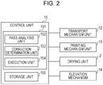
- Fig. 2 is a block diagram of the printing apparatus illustrated in Fig. 1 .
- Fig. 3 is a diagram illustrating a process in which the printing apparatus illustrated in Fig. 1 prints an image.
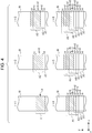
- Fig. 4 is a diagram illustrating a process in which the printing apparatus of the related art performs ejection position change correction and prints an image.
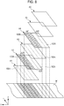
- Fig. 5 is a diagram illustrating a process in which the printing apparatus illustrated in Fig. 1 performs the ejection position change correction and prints an image.
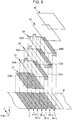
- Fig. 6 is a diagram illustrating a process in which the printing apparatus illustrated in Fig. 1 performs the ejection position change correction and prints an image.
- Fig. 7 is a flowchart illustrating a control operation of a control unit which is included in the printing apparatus illustrated in Fig. 1 .
- Fig. 1 three axes of an x-axis, a y-axis, and a z-axis which are orthogonal to each other are illustrated in Fig. 1 , and Fig. 3 to Fig. 6 for the sake of convenient description.
- the x-axis is formed in one direction (width (depth in the figure) of the printing apparatus) of a horizontal direction
- the y-axis is formed in a direction (longitudinal direction of the printing apparatus) perpendicular to the x-axis in the horizontal direction
- the z-axis is formed in a vertical direction (up and down direction).
- a front end side of each arrow which is illustrated is referred to as a "positive side (+ side)", and a base end side thereof is referred to as a “negative side (- side)".
- An upper side of Fig. 1 , and Fig. 3 to Fig. 6 is referred to as “top (top side)”, and a lower side thereof is referred to as “bottom (bottom side)”.
- a printing apparatus 1 executes a printing method of the invention, and includes a machine base 11, a transport mechanism unit (transport unit) 12 which transports a workpiece W as a recording medium (hereinafter referred to as the work W), a printing mechanism unit (printing unit) 13 which performs printing by providing ink 100 on the work W, a drying unit 2 which dries the ink 100 on the work W, and an elevation mechanism 14.
- a direction orthogonal to a transport direction in which the work W is transported is referred to as an x-axis direction
- a direction parallel with the transport direction is referred to as a y-axis direction
- a direction orthogonal to the x-axis direction and the y-axis direction is referred to as a z-axis direction.
- the transport mechanism unit 12 includes a delivering device 3 which delivers the long work W which is wound in a roll shape, a winding device 4 which winds the printed work W, and a supporting device 5 which is provided on the machine base 11 and supports the work W during printing.
- the delivering device 3 is disposed further on an upstream side than the machine base 11 in a sending direction (y-axis direction) of the work W.
- the delivering device 3 includes a sending roller (delivery reel) 31 to which the work W is wound in a roll shape and which sends the work W, and a tensioner 32 which applies tension to the work W between the sending roller 31 and the supporting device 5.
- the sending roller 31 is connected to a motor (not illustrated), and can be rotated by an operation of the motor.
- a material to be printed can be used as the work W.
- the material to be printed includes textile which is printed, clothing, other clothing products, or the like.
- the textile includes fabric, knitted fabric, non-woven fabric, or the like of such as a natural fiber such as cotton, silk, or wool, a chemical fiber such as nylon, or a composite fiber to which the natural fiber and the chemical fiber are mixed.
- clothing or other apparel products also include textile or the like before or after being cut, which exist as a part of a state before being sewed, in addition to furniture of such as a T-shirt, a handkerchief, a scarf, a towel, a carrier-bag, a clothing bag, a curtain, a sheet, or a bed cover which are sewed.
- normal paper, fine paper, special paper for ink jet recording such as glossy paper, or the like can be used as the work W.
- a plastic film for ink jet printing in which surface treatment is not made that is, an ink absorbing layer is not formed
- a material, which is coated with plastic, such as paper, or a material to which a plastic film is attached can also be used as the work W.
- the plastic is not limited in particular, and for example, polyvinyl chloride, polyethylene terephthalate, polycarbonate, polystyrene, polyurethane, polyethylene, and polypropylene can be used as the plastic.
- the winding device 4 is disposed further on a downstream side than the machine base 11 in the sending direction (y-axis direction) of the work W with respect to the delivering device 3.
- the winding device 4 includes a winding roller (winding reel) 41 which winds the work W in a roll shape, and tensioners 42, 43, and 44 which apply tension to the work W between the winding roller 41 and the supporting device 5.
- the winding roller 41 is connected to a motor (not illustrated), and can be rotated by an operation of the motor.
- the tensioners 42 to 44 are arranged with a gap between each other in an ascending order with increasing distance from the winding roller 41.
- the supporting device 5 is disposed between the delivering device 3 and the winding device 4.
- the supporting device 5 includes a main driving roller 51 and a follower roller 52 which are separately disposed in the y-axis direction, an endless belt 53 which is stretched over the main driving roller 51 and the follower roller 52 and supports the work W over an upper surface (supporting surface), and tensioners 54 and 55 which apply tension to the work W between the main driving roller 51 and the follower roller 52.
- the main driving roller 51 is connected to a motor (not illustrated), and can be rotated by an operation of the motor.
- the follower roller 52 receives a rotating force of the main driving roller 51 through the endless belt 53, and can rotate in conjunction with the main driving roller 51.
- the endless belt 53 has a front surface on which there is an adhesive layer with adhesiveness. A part of the work W is adhesively fixed to the adhesive layer, and the work W is transported in the y-axis direction. In addition, while the work W is transported, the work W is printed. In addition, after being printed, the work W is peeled from the endless belt 53.
- the tensioners 54 and 55 are also disposed with a gap between each other in the y-axis direction in the same manner as the main driving roller 51 and the follower roller 52.
- the work W can be interposed between the tensioner 54 and the main driving roller 51 on the endless belt 53, and the work W can be interposed between the tensioner 55 and the follower roller 52 on the endless belt 53.
- the work W to which tension is applied by the tensioners 54 and 55 is fixed to the endless belt 53 to be transported in a state where the tension is applied.
- the work W is prevented, for example, from being wrinkled during transport, and thus, in a case of printing, the printing can be performed accurately and with high quality.
- the printing mechanism unit 13 includes a carriage unit 132 including multiple ink jet heads 131 which perform recording by ejecting the ink 100 onto the work W for printing, and an X-axis table (not illustrated) which movably supports the carriage unit 132 in the x-axis direction.
- Each of the ink jet heads 131 includes a head body which is filled with the ink 100 and in which a head inner flow path is formed, and multiple nozzle groups 6 which respectively have openings.
- the head body includes piezoelectric elements (piezoelectric members) respectively corresponding to ejection nozzles, and if pressure is applied to the piezoelectric elements, the ink 100 is ejected from the nozzle group 6 as droplets.
- the ink jet heads 131 stand by at a position (standby position) far apart from the work W (endless belt 53) when viewing from the z-axis direction, in a state where the ink 100 is not ejected.
- the work W which is delivered by the delivering device 3 is intermittently sent (performs subscan) in the y-axis direction in a state of being adhesively fixed to the endless belt 53, and the ink 100 is ejected from the nozzle group 6 toward the work W which is adhesively fixed, while the carriage unit 132 reciprocates (performs main scan) in the x-axis direction.
- This operation can be performed until printing is completed and an image pattern is formed on the work W.
- the image pattern may be formed by multicolor printing (color printing), and may be formed by single color printing.
- the ink 100 has four colors of, for example, cyan (C), magenta (M), yellow (Y), and black (K), which are obtained by mixing dye or pigment that is a colorant into water that is a solvent.
- various types of the ink 100 are independently ejected from the ink jet heads 131.
- the elevation mechanism 14 illustrated in Fig. 1 and Fig. 2 can adjust a height of the nozzle group 6.
- the elevation mechanism 14 can be configured to include, for example, a motor, a ball screw, and a linear guide.
- an encoder can be embedded in the motor.
- a height of the ink jet head 131 can be detected based on the amount of rotation which is detected by the encoder.
- the elevation mechanism 14 is also electrically connected to a control unit 15.
- a distance between the nozzle group 6 and the work W can be adjusted by the elevation mechanism 14. Hence, it is possible to perform good printing in accordance with a material of the work W.
- the drying unit 2 is disposed between the supporting device 5 and the winding roller 41 of the winding device 4, further on a downstream side than the printing mechanism unit 13 in the transport direction of the work W.
- the drying unit 2 includes a chamber 21 and a coil 22 which is disposed within the chamber 21.
- the coil 22 is, for example, a heat emitting unit which is configured by a nichrome wire and emits heat by receiving electric power.
- the ink 100 on the work W which passes through the chamber 21 can be dried by heat that is generated by the coil 22.
- control unit 15 is electrically connected to the drying unit 2, the transport mechanism unit 12, the printing mechanism unit 13, and the elevation mechanism 14, and has a function of controlling operations thereof.
- control unit 15 includes a central processing unit (CPU) 151 and a storage unit 155.
- CPU central processing unit
- the CPU 151 executes a program for various types of processing such as the aforementioned printing.
- the CPU 151 functions as a pass analysis unit (decision unit) 152, a correction determination unit 153, and an execution unit 154.
- the pass analysis unit 152 performs pass analysis of deciding a position where the ink 100 is ejected into a forward path and a backward path, based on image data which is input.
- the correction determination unit 153 performs pass shifting (will be described below) in data which is obtained by performing pass analysis using the pass analysis unit 152.
- the execution unit 154 performs printing, based on the data which is obtained by performing pass shifting using the correction determination unit 153.
- the storage unit 155 includes, for example, an electrically erasable programmable read only memory (EEPROM) which is a type of a nonvolatile semiconductor memory, or the like, and can store various programs or the like.
- EEPROM electrically erasable programmable read only memory
- the ink 100 is ejected while reciprocating is performed n number of times (n is a positive integer of two or larger) and thereby an image is formed as illustrated in Fig. 3 .
- n a forward path of a first time
- a printing area A1 which is printed in a first pass and a printing area A2 which is printed in a second pass have the same length L in the transport direction of the work W (also the same as at a printing area A3 or later).
- the printing area A1 is formed by ejecting the ink 100 onto an area, which is denoted by hatching, of the work W in Fig. 3 during a first pass.
- the printing area A2 is formed by shifting further on an upstream side than the printing area A1 in the transport direction.
- the amount of the printing area A2 which is shifted is 1/4 of a length L of the printing area A1. That is, the printing area A1 and the printing area A2 overlap each other by 3/4 of the length L and are shifted by 1/4 of the length L.
- printing areas A3, A4, A5, and A6 are formed in the same manner as this.
- a color of an area made by printing on the unprinted work W using ink 100C with a ratio between yellow (Y) and black (K) of 25:3 is referred to as a color a
- a color of an area made by printing on the work which is previously printed in the ink 100 using the ink 100C with a ratio between yellow (Y) and black (K) of 25:3 is referred to as a color b.
- the entire printing area A1 is printed with the color a.
- a 1/4 area on a downstream side of the printing area A1 is maintained to be the color a.
- an area where the printing area A1 and the printing area A2 overlap each other becomes a color a+b.
- 1/4 area on an upstream side of the printing area A2 has the color a. "+" indicates overlap of colors.
- a color of 1/4 area on the downstream side is the color a
- a color of an area where the printing area A1 and the printing area A2 overlap each other is the color a+b, in the printing area A1.
- an area where the printing area A1, the printing area A2, and the printing area A3 overlap each other has a color a+b+b (color a+2b).
- an area where the printing area A2 and the printing area A3 overlap each other has the color a+b.
- an area in which only the printing area A3 is printed has the color a.
- areas of the color a, the color a+b, the color a+2b, the color a+3b, the color a+3b, the color a+3b, the color a+2b, the color a+b, and the color a are sequentially lined up from the downstream side.
- a portion which becomes a product by the printing of the fourth pass is obtained, and a portion of an area which becomes a product increases by the fifth pass or later passes.
- the ink 100 of black (K) which is originally planned to be ejected in the first pass, the third pass, and the fourth pass within the first to fourth passes is now ejected only in the second pass. That is, ejection position change correction (pass shifting) in which ejection position is changed is performed.
- a ratio which is 25:3 before being corrected, between yellow (Y) and black (K) in each pass becomes a ratio of 25:0 between yellow (Y) and black (K) in the first pass.
- the ratio between yellow (Y) and black (K) in the second pass becomes 25:12.
- the ratio between yellow (Y) and black (K) in the third pass becomes 25:0.
- the ratio between yellow (Y) and black (K) in the fourth pass becomes 25:0.
- the ink 100 of black (K) which is ejected into the fifth pass, the seventh pass, and the eighth pass is ejected into the sixth pass (also the same as in a ninth pass or later).
- a color appearing in a case where the ink 100 in which a ratio between yellow (Y) and black (K) is 25:0 is landed on the work W on which the ink 100 is not landed yet is regarded as a color a (hereinafter, ink in which the ratio between yellow (Y) and black (K) is 25:0 is referred to as ink 100A).
- ink 100A ink in which the ratio between yellow (Y) and black (K) is 25:0
- a color appearing in a case where the ink 100A is landed so as to overlap another ink 100 is regarded as a color b.
- a color appearing in a case where the ink 100 in which the ratio between yellow (Y) and black (K) is 25:12 is landed on the work W on which the ink 100 is not landed yet is referred to as a color c (hereinafter, ink in which the ratio between yellow (Y) and black (K) is 25:12 is referred to as ink 100B).
- ink 100B ink in which the ratio between yellow (Y) and black (K) is 25:12
- a color appearing in a case where the ink 100B is landed so as to overlap another ink 100 is referred to as a color d.
- areas of the color a, the color a+d, the color a+b+d, the color a+2b+d, the color 3b+c, the color a+2b+d, the color a+b+d, the color a+d, and the color c are sequentially formed in parallel from a downstream side in an ascending order.
- An image which is formed by performing the pass shifting has a portion in which areas of the color a+2b+d and the color 3b+c become actual products, and other portions are discarded.
- printing in three passes of the four passes can be omitted, and thus, deviation of the landing position of the ink 100 in the forward path and the backward path can be reduced as described above.
- the ink 100 which is omitted by the pass shifting is allocated to other passes, and thus, a total amount of ejection of the ink 100 becomes equal and degradation of image quality can be less likely to occur in view of the entire image.
- the printing apparatus 1 can prevent image quality from being degraded due to the pass shifting. Hereinafter, this will be described.
- the ink 100A in which a ratio between the yellow (Y) and black (K) is 25:0 is ejected onto the entire printing area A1.
- the ink 100B in which a ratio between yellow (Y) and black (K) is 25:12 is ejected onto 3/4 area A21 from a downstream side.
- the ink 100A is ejected onto 1/4 area A22 from an upper area of the printing area A2.
- the ink 100A is ejected onto 1/2 area A31 from a downstream side.
- the ink 100B is ejected onto 1/4 area A32 on an upstream side of the area A31.
- the ink 100A is ejected onto 1/4 area A33 on an upstream side of the area A32.
- the ink 100A in which a ratio between yellow (Y) and black (K) is 25:0 is ejected onto the entire printing area A4.
- a portion onto which the ink 100B is directly landed in the work W can be omitted.
- a color of a portion which actually becomes a product is only the color a+2b+d, regardless of the pass shifting which is performed.
- step S101 pass analysis is performed based on image data which is input to the printing apparatus 1. The amount of ink 100 which will be ejected onto the pass is determined.
- step S102 it is determined whether or not the pass shifting will be performed based on a work gap or the like. In a case where it is determined that there is a possibility that image quality is degraded if the pass shifting is not performed in step S102, the following pass shifting processing is performed in step S103.
- the printing areas A1 to A4 are respectively divided into four areas along the transport direction. In addition, it is determined whether or not the pass shifting is performed for each divided area, that is, it is determined which of the ink 100A and the ink 100B will be ejected.
- the ink 100B is ejected onto the 3/4 area A21 from a downstream side among the divided four areas of the printing area A2. In addition, it is determined that the ink 100A is ejected onto the area A31 and the area A33 in the area A3, and it is determined that the ink 100B is ejected onto the area A32. In addition, it is determined that the ink 100A is ejected onto the entire areas of the printing area A1 and the printing area A4.
- the printing areas A1 to A4 are respectively divided, the ink 100A or the ink 100B is allocated to each divided area, and thereby, there are portions where the pass shifting is performed in an image which is formed, that is, the inks 100B can be prevented from being landed so as to overlap each other. Hence, it is possible to prevent image quality of an image which is obtained from being degraded.
- the ink 100A and the ink 100B are also allocated in the fifth pass or later in the same manner as in the first pass to fourth pass.
- step S104 printing is performed according to the setting which is determined in step S103. Thereby, it is possible to form an image in which the pass shifting is performed.
- step S102 printing is performed in a state where the pass analysis is performed in step S101 without the pass shifting.
- the pass shifting can be performed by selecting whether or not each of the multiple nozzles included in the nozzle group ejects the ink 100.
- the printing apparatus 1 provides a setting in which an image is formed by using four passes such as the first pass to the fourth pass or the fifth pass to the eighth pass as one set, but the invention is not limited to this.
- an image may be formed by setting two passes, three passes, five passes or more as one set.
- each pass is divided into n areas in a transport direction, and the ink 100A and the ink 100B are allocated to each of the divided areas.
- Fig. 8 is a diagram illustrating a process in which a printing apparatus (second embodiment) of the invention performs the ejection position change correction and prints an image.
- the present embodiment is the same as the first embodiment except for control when ejection position change correction is performed.
- the ink 100A and the ink 100B are allocated as follows when the pass shifting is performed.
- the ink 100A is ejected onto the entire printing area A1.
- the ink 100B is ejected onto a 1/2 area A23 from a downstream side.
- the ink 100A is ejected onto a 1/2 area A24 on an upstream side of the area A23 of the printing area A2.
- the ink 100A is ejected onto the entire printing area A3.
- the ink 100B is ejected onto a 1/2 area A41 from a downstream side.
- the ink 100A is ejected onto a 1/2 area A42 on an upstream side of the area A41 of the printing area A4.
- a portion where the ink 100B is directly landed on the work W can be omitted in the same manner as in the first embodiment.
- the pass shifting is performed, an image with high printing accuracy can be formed.
- Fig. 9 is a diagram illustrating a process in which a printing apparatus (third embodiment) of the invention performs the ejection position change correction and prints an image.
- the present embodiment is the same as the first embodiment except for control when ejection position change correction is performed.
- the ink 100A and the ink 100B are allocated as follows when the pass shifting is performed.
- the ink 100B is ejected onto the entire printing area A1.
- the ink 100A is ejected onto a 3/4 area A21 from a downstream side.
- the ink 100B is ejected onto a 1/4 area A22 on an upstream side of the area A21 of the printing area A2.
- the ink 100A is ejected onto a 1/2 area A31 from a downstream side.
- the ink 100A is ejected onto a 1/4 area A32 on an upstream side of the area A31 of the printing area A3.
- the ink 100B is ejected onto a 1/4 area A33 on an upstream side of the area A31 of the printing area A3.
- the ink 100A is ejected onto a 3/4 area A41 from a downstream side.
- the ink 100B is ejected onto a 1/4 area A42 on an upstream side of the area A41 of the printing area A4.
- the ink 100B it is possible to prevent the ink 100B from being landed so as to overlap the ink 100A and the ink 100B. That is, in the present embodiment, the ink 100B is ejected onto areas which are different from overlapping portions where the printing areas A1 to A4 overlap each other in a plan view of the work W. Thereby, it is possible to omit a color d which is generated by landing the ink 100B so as to overlap the ink 100A and the ink 100B. Hence, in the work W, a color of a portion which is actually used as a product becomes a color 3b+c.
- each unit configuring the printing apparatus can be replaced with elements having an arbitrary configuration that can perform the same function.
- an arbitrary configuration element may be added thereto.
- the printing apparatus according to the invention may be configured by combining arbitrary two or more configurations (characteristics) of the respective embodiments.
- the printing mechanism unit ejects ink as droplets with the same size
- the invention is not limited to this, and the ink may be ejected as droplets with sizes of two types or more.
- the ejection position change correction described above may be performed for each ink of droplets with each size.
Landscapes
- Engineering & Computer Science (AREA)
- Textile Engineering (AREA)
- Quality & Reliability (AREA)
- Ink Jet (AREA)
Abstract
Description
- The present invention relates to a printing apparatus and a printing method.
- A printing apparatus which performs printing on a recording medium using ink has been used (for example,
JP-A-2010-5827 JP-A-2010-5827 - The printing apparatus has a possibility that significant deviation of a position where ink is landed on a forward path and a backward path of the printing unit occurs according to a distance between the recording medium and the printing unit, or a material of the recording medium, and quality of an image which is obtained is degraded. Accordingly, it is considered that ejection position change correction is performed in which ink that is ejected into the other path is ejected into one path such that the ink is ejected only into one path of a forward path and a backward path of a printing unit.
- However, the printing apparatus described in
JP-A-2010-5827 - An advantage of some aspects of the invention is to provide a printing apparatus and a printing method which can prevent or reduce an obtained image from being degraded.
- The advantage is achieved by the following aspects of the invention.
- According to an aspect of the invention, there is provided a printing apparatus including: a printing unit that forms a first printing area in a recording medium which is transported by ejecting first ink onto a first path in a direction crossing a transport direction of the recording medium, forms a second printing area in the recording medium by ejecting second ink onto a second path different from the first path, and thereby forms an image which is configured with the first printing area and the second printing area; a decision unit that decides a first ejection position of the first ink in the first path and a second ejection position of the second ink in the second path, when the image is formed; and a correction determination unit that performs ejection position change correction in which the first ejection position is changed such that the first ink is ejected onto the second path and the second ejection position is changed such that a part of the second ink is ejected onto the first path, based on decision results of the decision unit.
- Thereby, for example, it is possible to prevent inks in which ejection position change correction is performed from overlapping each other. Hence, it is possible to prevent image quality from being degraded due to overlapping of the inks in which the ejection position change correction is performed.
- In the printing apparatus of the aspect of the invention, the printing unit may form an overlapping portion in which the first printing area and the second printing area partially overlap each other in a plan view of the recording medium.
- Thereby, it is possible to prevent the degradation of image quality from occurring in an image, in a case where ejection position change correction is performed.
- In the printing apparatus of the aspect of the invention, the second ink which is ejected onto the first printing area may be shifted from the first ink which is ejected onto the second printing area in a plan view of the recording medium, when being ejected, in the ejection position change correction.
- Thereby, degradation of image quality which occurs in an image in a case where ejection position change correction is performed can be more effectively prevented or suppressed.
- In the printing apparatus of the aspect of the invention, in a case where the printing unit forms the image by moving n number of times (n is a positive integer greater than or equal to two), the correction determination unit may divide the second printing area into n areas and determine whether to perform the ejection position change correction for each of the divided areas or not.
- Thereby, degradation of image quality which occurs in an image in a case where ejection position change correction is performed can be more effectively prevented or suppressed.
- In the printing apparatus of the aspect of the invention, the second ink which is ejected onto the first printing area may be ejected onto the overlapping portion, in the ejection position change correction.
- Thereby, it is possible to prevent inks in which ejection position change correction is performed from overlapping each other.
- In the printing apparatus of the aspect of the invention, the second ink which is ejected onto the first printing area may be ejected into a position different from the overlapping portion, in the ejection position change correction.
- Thereby, it is possible to prevent inks in which ejection position change correction is performed from overlapping each other.
- In the printing apparatus of the aspect of the invention, the printing unit may eject at least two types of ink whose hues are different from each other, and the correction determination unit may perform the ejection position change correction for ink with a smaller amount of ejection per unit area in the image among the two types of ink.
- Thereby, it is possible to prevent inks in which ejection position change correction is performed from overlapping each other.
- According to another aspect of the invention, there is provided a printing method of performing printing by using a printing apparatus including a printing unit that forms a first printing area in a recording medium which is transported by ejecting first ink onto a first path in a direction crossing a transport direction of the recording medium, forms a second printing area in the recording medium at a position different from the first printing area by ejecting second ink onto a second path different from the first path, and thereby forms an image which is configured with the first printing area and the second printing area, and a decision unit that decides a first ejection position of the first ink in the first path and a second ejection position of the second ink in the second path, when the image is formed, the method including: performing ejection position change correction in which the first ejection position is changed such that the first ink is ejected onto the second path and the second ejection position is changed such that a part of the second ink is ejected onto the first path.
- Thereby, for example, it is possible to prevent inks in which ejection position change correction is performed from overlapping each other. Hence, it is possible to prevent image quality from being degraded due to overlapping of the inks in which the ejection position change correction is performed.
- Embodiments of the invention will now be described by way of example only with reference to the accompanying drawings, wherein like numbers reference like elements.
-
Fig. 1 is a side view schematically illustrating a first embodiment of a printing apparatus according to the invention. -
Fig. 2 is a block diagram of the printing apparatus illustrated inFig. 1 . -
Fig. 3 is a diagram illustrating a process in which the printing apparatus illustrated inFig. 1 prints an image. -
Fig. 4 is a diagram illustrating a process in which the printing apparatus of the related art performs ejection position change correction and prints an image. -
Fig. 5 is a diagram illustrating a process in which the printing apparatus illustrated inFig. 1 performs the ejection position change correction and prints an image. -
Fig. 6 is a diagram illustrating a process in which the printing apparatus illustrated inFig. 1 performs the ejection position change correction and prints an image. -
Fig. 7 is a flowchart illustrating a control operation of a control unit which is included in the printing apparatus illustrated inFig. 1 . -
Fig. 8 is a diagram illustrating a process in which a printing apparatus (second embodiment) of the invention performs the ejection position change correction and prints an image. -
Fig. 9 is a diagram illustrating a process in which a printing apparatus (third embodiment) of the invention performs the ejection position change correction and prints an image. - Hereinafter, a printing apparatus and a printing method according to the invention will be described in detail, based on a preferred embodiment illustrated in the accompanying drawings.
-
Fig. 1 is a side view schematically illustrating a first embodiment of a printing apparatus according to the invention.Fig. 2 is a block diagram of the printing apparatus illustrated inFig. 1 .Fig. 3 is a diagram illustrating a process in which the printing apparatus illustrated inFig. 1 prints an image.Fig. 4 is a diagram illustrating a process in which the printing apparatus of the related art performs ejection position change correction and prints an image.Fig. 5 is a diagram illustrating a process in which the printing apparatus illustrated inFig. 1 performs the ejection position change correction and prints an image.Fig. 6 is a diagram illustrating a process in which the printing apparatus illustrated inFig. 1 performs the ejection position change correction and prints an image.Fig. 7 is a flowchart illustrating a control operation of a control unit which is included in the printing apparatus illustrated inFig. 1 . - Hereinafter, three axes of an x-axis, a y-axis, and a z-axis which are orthogonal to each other are illustrated in
Fig. 1 , andFig. 3 toFig. 6 for the sake of convenient description. The x-axis is formed in one direction (width (depth in the figure) of the printing apparatus) of a horizontal direction, and the y-axis is formed in a direction (longitudinal direction of the printing apparatus) perpendicular to the x-axis in the horizontal direction, and the z-axis is formed in a vertical direction (up and down direction). In addition, a front end side of each arrow which is illustrated is referred to as a "positive side (+ side)", and a base end side thereof is referred to as a "negative side (- side)". An upper side ofFig. 1 , andFig. 3 toFig. 6 is referred to as "top (top side)", and a lower side thereof is referred to as "bottom (bottom side)". - As illustrated in
Fig. 1 andFig. 2 , aprinting apparatus 1 executes a printing method of the invention, and includes amachine base 11, a transport mechanism unit (transport unit) 12 which transports a workpiece W as a recording medium (hereinafter referred to as the work W), a printing mechanism unit (printing unit) 13 which performs printing by providing ink 100 on the work W, adrying unit 2 which dries the ink 100 on the work W, and anelevation mechanism 14. - In the present embodiment, a direction orthogonal to a transport direction in which the work W is transported is referred to as an x-axis direction, a direction parallel with the transport direction is referred to as a y-axis direction, and a direction orthogonal to the x-axis direction and the y-axis direction is referred to as a z-axis direction.
- The
transport mechanism unit 12 includes a deliveringdevice 3 which delivers the long work W which is wound in a roll shape, awinding device 4 which winds the printed work W, and a supportingdevice 5 which is provided on themachine base 11 and supports the work W during printing. - The delivering
device 3 is disposed further on an upstream side than themachine base 11 in a sending direction (y-axis direction) of the work W. The deliveringdevice 3 includes a sending roller (delivery reel) 31 to which the work W is wound in a roll shape and which sends the work W, and atensioner 32 which applies tension to the work W between thesending roller 31 and the supportingdevice 5. The sendingroller 31 is connected to a motor (not illustrated), and can be rotated by an operation of the motor. - In addition, a material to be printed can be used as the work W. The material to be printed includes textile which is printed, clothing, other clothing products, or the like. The textile includes fabric, knitted fabric, non-woven fabric, or the like of such as a natural fiber such as cotton, silk, or wool, a chemical fiber such as nylon, or a composite fiber to which the natural fiber and the chemical fiber are mixed. In addition, clothing or other apparel products also include textile or the like before or after being cut, which exist as a part of a state before being sewed, in addition to furniture of such as a T-shirt, a handkerchief, a scarf, a towel, a carrier-bag, a clothing bag, a curtain, a sheet, or a bed cover which are sewed.
- In addition to the aforementioned material to be printed, normal paper, fine paper, special paper for ink jet recording such as glossy paper, or the like can be used as the work W. In addition, for example, a plastic film for ink jet printing in which surface treatment is not made (that is, an ink absorbing layer is not formed), a material, which is coated with plastic, such as paper, or a material to which a plastic film is attached can also be used as the work W. The plastic is not limited in particular, and for example, polyvinyl chloride, polyethylene terephthalate, polycarbonate, polystyrene, polyurethane, polyethylene, and polypropylene can be used as the plastic.
- The winding
device 4 is disposed further on a downstream side than themachine base 11 in the sending direction (y-axis direction) of the work W with respect to the deliveringdevice 3. The windingdevice 4 includes a winding roller (winding reel) 41 which winds the work W in a roll shape, andtensioners roller 41 and the supportingdevice 5. The windingroller 41 is connected to a motor (not illustrated), and can be rotated by an operation of the motor. Thetensioners 42 to 44 are arranged with a gap between each other in an ascending order with increasing distance from the windingroller 41. - The supporting
device 5 is disposed between the deliveringdevice 3 and the windingdevice 4. The supportingdevice 5 includes amain driving roller 51 and afollower roller 52 which are separately disposed in the y-axis direction, anendless belt 53 which is stretched over themain driving roller 51 and thefollower roller 52 and supports the work W over an upper surface (supporting surface), andtensioners main driving roller 51 and thefollower roller 52. - The
main driving roller 51 is connected to a motor (not illustrated), and can be rotated by an operation of the motor. In addition, thefollower roller 52 receives a rotating force of themain driving roller 51 through theendless belt 53, and can rotate in conjunction with themain driving roller 51. - The
endless belt 53 has a front surface on which there is an adhesive layer with adhesiveness. A part of the work W is adhesively fixed to the adhesive layer, and the work W is transported in the y-axis direction. In addition, while the work W is transported, the work W is printed. In addition, after being printed, the work W is peeled from theendless belt 53. - The
tensioners main driving roller 51 and thefollower roller 52. - The work W can be interposed between the
tensioner 54 and themain driving roller 51 on theendless belt 53, and the work W can be interposed between thetensioner 55 and thefollower roller 52 on theendless belt 53. Thereby, the work W to which tension is applied by thetensioners endless belt 53 to be transported in a state where the tension is applied. By doing so, the work W is prevented, for example, from being wrinkled during transport, and thus, in a case of printing, the printing can be performed accurately and with high quality. - The
printing mechanism unit 13 includes acarriage unit 132 including multiple ink jet heads 131 which perform recording by ejecting the ink 100 onto the work W for printing, and an X-axis table (not illustrated) which movably supports thecarriage unit 132 in the x-axis direction. Each of the ink jet heads 131 includes a head body which is filled with the ink 100 and in which a head inner flow path is formed, andmultiple nozzle groups 6 which respectively have openings. - The head body includes piezoelectric elements (piezoelectric members) respectively corresponding to ejection nozzles, and if pressure is applied to the piezoelectric elements, the ink 100 is ejected from the
nozzle group 6 as droplets. - The ink jet heads 131 stand by at a position (standby position) far apart from the work W (endless belt 53) when viewing from the z-axis direction, in a state where the ink 100 is not ejected.
- In the
printing apparatus 1, the work W which is delivered by the deliveringdevice 3 is intermittently sent (performs subscan) in the y-axis direction in a state of being adhesively fixed to theendless belt 53, and the ink 100 is ejected from thenozzle group 6 toward the work W which is adhesively fixed, while thecarriage unit 132 reciprocates (performs main scan) in the x-axis direction. This operation can be performed until printing is completed and an image pattern is formed on the work W. The image pattern may be formed by multicolor printing (color printing), and may be formed by single color printing. - The ink 100 has four colors of, for example, cyan (C), magenta (M), yellow (Y), and black (K), which are obtained by mixing dye or pigment that is a colorant into water that is a solvent. In addition, various types of the ink 100 are independently ejected from the ink jet heads 131.
- The
elevation mechanism 14 illustrated inFig. 1 andFig. 2 can adjust a height of thenozzle group 6. Theelevation mechanism 14 can be configured to include, for example, a motor, a ball screw, and a linear guide. In addition, an encoder can be embedded in the motor. A height of theink jet head 131 can be detected based on the amount of rotation which is detected by the encoder. Theelevation mechanism 14 is also electrically connected to acontrol unit 15. - As such, a distance between the
nozzle group 6 and the work W can be adjusted by theelevation mechanism 14. Hence, it is possible to perform good printing in accordance with a material of the work W. - As illustrated in
Fig. 1 , the dryingunit 2 is disposed between the supportingdevice 5 and the windingroller 41 of the windingdevice 4, further on a downstream side than theprinting mechanism unit 13 in the transport direction of the work W. - The drying
unit 2 includes achamber 21 and acoil 22 which is disposed within thechamber 21. Thecoil 22 is, for example, a heat emitting unit which is configured by a nichrome wire and emits heat by receiving electric power. In addition, the ink 100 on the work W which passes through thechamber 21 can be dried by heat that is generated by thecoil 22. - As illustrated in
Fig. 2 , thecontrol unit 15 is electrically connected to thedrying unit 2, thetransport mechanism unit 12, theprinting mechanism unit 13, and theelevation mechanism 14, and has a function of controlling operations thereof. In addition, thecontrol unit 15 includes a central processing unit (CPU) 151 and astorage unit 155. - The
CPU 151 executes a program for various types of processing such as the aforementioned printing. In addition, theCPU 151 functions as a pass analysis unit (decision unit) 152, acorrection determination unit 153, and anexecution unit 154. - The
pass analysis unit 152 performs pass analysis of deciding a position where the ink 100 is ejected into a forward path and a backward path, based on image data which is input. - The
correction determination unit 153 performs pass shifting (will be described below) in data which is obtained by performing pass analysis using thepass analysis unit 152. Theexecution unit 154 performs printing, based on the data which is obtained by performing pass shifting using thecorrection determination unit 153. - The
storage unit 155 includes, for example, an electrically erasable programmable read only memory (EEPROM) which is a type of a nonvolatile semiconductor memory, or the like, and can store various programs or the like. - In the
printing apparatus 1, the ink 100 is ejected while reciprocating is performed n number of times (n is a positive integer of two or larger) and thereby an image is formed as illustrated inFig. 3 . Hereinafter, detailed description thereof will be made, and a forward path of a first time is referred to as a first pass (pass of n = 1), and a backward path of a first time is referred to as a second pass (pass of n = 2). In addition, a forward path of a second time is referred to as a third pass (pass of n = 3), and a backward path of a second time is referred to as a fourth pass (pass of n = 4) (in the same manner, a positive integer is replaced with n also in the forward path of a third time or later). In addition, a printing area A1 which is printed in a first pass and a printing area A2 which is printed in a second pass have the same length L in the transport direction of the work W (also the same as at a printing area A3 or later). - In the
printing apparatus 1, first, the printing area A1 is formed by ejecting the ink 100 onto an area, which is denoted by hatching, of the work W inFig. 3 during a first pass. Subsequently, the printing area A2 is formed by shifting further on an upstream side than the printing area A1 in the transport direction. At this time, the amount of the printing area A2 which is shifted is 1/4 of a length L of the printing area A1. That is, the printing area A1 and the printing area A2 overlap each other by 3/4 of the length L and are shifted by 1/4 of the length L. In theprinting apparatus 1, printing areas A3, A4, A5, and A6 are formed in the same manner as this. - Hereinafter, a case where an image with dot density (density of droplets) of yellow (Y) of 100% and black (K) of 12% is printed will be described as an example. In addition, in this case, for example, yellow of 100% and black of 12% are uniformly divided into four passes to be printed, and a ratio between yellow (Y) and black (K) is 25:3 in each pass. Hereinafter, ink with the ratio is referred to as "ink 100C".
- Although the same ink is used, spreading of the ink in case where printing is performed on the unprinted work W is different from spreading of the ink in a case where printing is performed on the printed work W. Accordingly, colors of the formed printing area differ between the cases where the area is formed by printing on an unprinted part of the work or printing on already printed part of the work.
- Hereinafter, a color of an area made by printing on the unprinted work W using ink 100C with a ratio between yellow (Y) and black (K) of 25:3 is referred to as a color a, and a color of an area made by printing on the work which is previously printed in the ink 100 using the ink 100C with a ratio between yellow (Y) and black (K) of 25:3 is referred to as a color b.
- In the
printing apparatus 1, when printing of the first pass is completed, the entire printing area A1 is printed with the color a. When printing of the second pass is completed, a 1/4 area on a downstream side of the printing area A1 is maintained to be the color a. In addition, an area where the printing area A1 and the printing area A2 overlap each other becomes a color a+b. In addition, 1/4 area on an upstream side of the printing area A2 has the color a. "+" indicates overlap of colors. - Now consider the print area colors when printing of the third pass is completed, a color of 1/4 area on the downstream side is the color a, and a color of an area where the printing area A1 and the printing area A2 overlap each other is the color a+b, in the printing area A1. In addition, an area where the printing area A1, the printing area A2, and the printing area A3 overlap each other has a color a+b+b (color a+2b). In addition, an area where the printing area A2 and the printing area A3 overlap each other has the color a+b. In addition, an area in which only the printing area A3 is printed has the color a.
- If printing is performed in the same manner, when printing of the fourth pass is completed, areas of the color a, the color a+b, the color a+2b, a color a+3b, a color a+2b, the color a+b, and the color a are sequentially lined up from a downstream side. When printing of a fifth pass is completed, areas of the color a, the color a+b, the color a+2b, the color a+3b, the color a+3b, the color a+2b, the color a+b, and the color a are sequentially lined up from the downstream side. When printing of a sixth pass is completed, areas of the color a, the color a+b, the color a+2b, the color a+3b, the color a+3b, the color a+3b, the color a+2b, the color a+b, and the color a are sequentially lined up from the downstream side.
- In the
printing apparatus 1, the area in which a color of the area is the color a+3b becomes an actual product, and the areas of the color a, the color a+b, and the color a+2b are discarded. As such, in theprinting apparatus 1, a portion which becomes a product by the printing of the fourth pass is obtained, and a portion of an area which becomes a product increases by the fifth pass or later passes. - In a general printing apparatus, in a case where ink is ejected toward an arbitrary position, deviation occurs at a landing position of the ink in a forward path and a backward path. This is because orientations of inertial forces acting on the ink in the forward path and the backward path are different from each other. Particularly, if a magnitude of ink droplets is relatively small or a distance between a nozzle and a recording medium is relatively long, significant deviation easily occurs at the landing position of the ink in the forward path and the backward path. In a case where the deviation occurs, "pass shifting" which will be described hereinafter is considered as means for reducing the deviation.
- Hereinafter, an example of the pass shifting of the
printing apparatus 1 will be described. Hereinafter, a case where the pass shifting is performed to the black ink 100 when printing Y100% andK 12% image will be described. - In the
printing apparatus 1, the ink 100 of black (K) which is originally planned to be ejected in the first pass, the third pass, and the fourth pass within the first to fourth passes is now ejected only in the second pass. That is, ejection position change correction (pass shifting) in which ejection position is changed is performed. - By performing the ejection position change correction, a ratio, which is 25:3 before being corrected, between yellow (Y) and black (K) in each pass becomes a ratio of 25:0 between yellow (Y) and black (K) in the first pass. The ratio between yellow (Y) and black (K) in the second pass becomes 25:12. The ratio between yellow (Y) and black (K) in the third pass becomes 25:0. The ratio between yellow (Y) and black (K) in the fourth pass becomes 25:0. Thereby, ejecting the ink 100 of black (K) into the first pass, the third pass, and the fourth pass can be omitted. In the same manner as also in the fifth pass to the eighth pass, the ink 100 of black (K) which is ejected into the fifth pass, the seventh pass, and the eighth pass is ejected into the sixth pass (also the same as in a ninth pass or later).
- An image which is obtained when printing is performed by performing the pass shifting will be described with reference to
Fig. 4 . Hereinafter, a color appearing in a case where the ink 100 in which a ratio between yellow (Y) and black (K) is 25:0 is landed on the work W on which the ink 100 is not landed yet is regarded as a color a (hereinafter, ink in which the ratio between yellow (Y) and black (K) is 25:0 is referred to asink 100A). In addition, a color appearing in a case where theink 100A is landed so as to overlap another ink 100 is regarded as a color b. In addition, a color appearing in a case where the ink 100 in which the ratio between yellow (Y) and black (K) is 25:12 is landed on the work W on which the ink 100 is not landed yet is referred to as a color c (hereinafter, ink in which the ratio between yellow (Y) and black (K) is 25:12 is referred to asink 100B). In addition, a color appearing in a case where theink 100B is landed so as to overlap another ink 100 is referred to as a color d. - In a case where printing is performed in the same manner as the aforementioned printing method, when printing in the first pass is completed, an area of the color a is formed. When printing in the second pass is completed, areas of the color a, the color a+d, and the color c are sequentially formed in parallel from a downstream side in an ascending order. When printing in the third pass is completed, areas of the color a, the color a+d, the color a+b+d, the color b+c, and the color a are sequentially formed in parallel from a downstream side in an ascending order. When printing in the fourth pass is completed, areas of the color a, the color a+d, the color a+b+d, the color a+2b+d, the
color 2b+c, the color a+b, and the color a are sequentially formed in parallel from a downstream side in an ascending order. When printing in the fifth pass is completed, areas of the color a, the color a+d, the color a+b+d, the color a+2b+d, thecolor 3b+c, the color a+2b, the color a+b, and the color a are sequentially formed in parallel from a downstream side in an ascending order. When printing in the sixth pass is completed, areas of the color a, the color a+d, the color a+b+d, the color a+2b+d, thecolor 3b+c, the color a+2b+d, the color a+b+d, the color a+d, and the color c are sequentially formed in parallel from a downstream side in an ascending order. - An image which is formed by performing the pass shifting has a portion in which areas of the color a+2b+d and the
color 3b+c become actual products, and other portions are discarded. In addition, by performing the pass shifting, printing in three passes of the four passes can be omitted, and thus, deviation of the landing position of the ink 100 in the forward path and the backward path can be reduced as described above. Furthermore, the ink 100 which is omitted by the pass shifting is allocated to other passes, and thus, a total amount of ejection of the ink 100 becomes equal and degradation of image quality can be less likely to occur in view of the entire image. - However, although the pass shifting is performed, if a color difference between the area of the color a+2b+d and the area of the
color 3b+c is relatively large, such color difference is recognized as streak unevenness in a portion which actually becomes a product and image quality is degraded. There is a possibility that significant degradation of image quality occurs when a difference between the color a and the color b and a difference between the color c and the color d are large. - The
printing apparatus 1 can prevent image quality from being degraded due to the pass shifting. Hereinafter, this will be described. - As described in
Fig. 5 , when the pass shifting is performed in theprinting apparatus 1, theink 100A in which a ratio between the yellow (Y) and black (K) is 25:0 is ejected onto the entire printing area A1. - In addition, when the printing area A2 is divided into four areas in the transport direction, the
ink 100B in which a ratio between yellow (Y) and black (K) is 25:12 is ejected onto 3/4 area A21 from a downstream side. In addition, theink 100A is ejected onto 1/4 area A22 from an upper area of the printing area A2. - In addition, when the printing area A3 is divided into four areas in the transport direction, the
ink 100A is ejected onto 1/2 area A31 from a downstream side. In addition, theink 100B is ejected onto 1/4 area A32 on an upstream side of the area A31. In addition, theink 100A is ejected onto 1/4 area A33 on an upstream side of the area A32. - The
ink 100A in which a ratio between yellow (Y) and black (K) is 25:0 is ejected onto the entire printing area A4. - By performing the pass shifting, a portion onto which the
ink 100B is directly landed in the work W can be omitted. Theink 100B which is ejected onto the printing area A2 and the printing area A3 is landed so as to overlap theink 100A. That is, theink 100B is ejected onto an overlapping portion in which the printing areas A1 to A4 overlap each other. Accordingly, it is possible to prevent the color c from appearing when theink 100B is directly landed onto the work W, as illustrated inFig. 6 . Hence, a color of a portion which actually becomes a product is only the color a+2b+d, regardless of the pass shifting which is performed. Thus, it is possible to prevent image quality from being degraded due to a color difference between the color a+2b+d and 3b+c which is caused by pass shifting of the related art. As a result, in theprinting apparatus 1, although the pass shifting is performed, an image with high printing accuracy can be formed. Areas onto which theink 100B is ejected is denoted by cross-hatching inFig. 6 . - Next, a control operation of the
control unit 15 will be described by using a flowchart illustrated inFig. 7 . - In step S101, pass analysis is performed based on image data which is input to the
printing apparatus 1. The amount of ink 100 which will be ejected onto the pass is determined. - Subsequently, in step S102, it is determined whether or not the pass shifting will be performed based on a work gap or the like. In a case where it is determined that there is a possibility that image quality is degraded if the pass shifting is not performed in step S102, the following pass shifting processing is performed in step S103.
- As illustrated in
Fig. 5 , the printing areas A1 to A4 are respectively divided into four areas along the transport direction. In addition, it is determined whether or not the pass shifting is performed for each divided area, that is, it is determined which of theink 100A and theink 100B will be ejected. - It is determined that the
ink 100B is ejected onto the 3/4 area A21 from a downstream side among the divided four areas of the printing area A2. In addition, it is determined that theink 100A is ejected onto the area A31 and the area A33 in the area A3, and it is determined that theink 100B is ejected onto the area A32. In addition, it is determined that theink 100A is ejected onto the entire areas of the printing area A1 and the printing area A4. - As such, the printing areas A1 to A4 are respectively divided, the
ink 100A or theink 100B is allocated to each divided area, and thereby, there are portions where the pass shifting is performed in an image which is formed, that is, theinks 100B can be prevented from being landed so as to overlap each other. Hence, it is possible to prevent image quality of an image which is obtained from being degraded. - The
ink 100A and theink 100B are also allocated in the fifth pass or later in the same manner as in the first pass to fourth pass. - Subsequently, in step S104, printing is performed according to the setting which is determined in step S103. Thereby, it is possible to form an image in which the pass shifting is performed.
- In a case where it is determined that the pass shifting is not performed in step S102, printing is performed in a state where the pass analysis is performed in step S101 without the pass shifting.
- As described above, when focusing on the printing area A2 and the printing area A3, according to the pass shifting of the related art, by changing an ejection position such that the ink 100 which is ejected onto the printing area A3 is ejected onto the printing area A2, only the
ink 100A that is the first ink is ejected onto the printing area A3, and only theink 100B that is the second ink is ejected onto the printing area A2. In contrast to this, in the invention, when the pass shifting is performed, not only an ejection position (first ejection position) of the ink 100 which is ejected onto the printing area A3 is changed to the printing area A2, but also an ejection position (second ejection position) of a part of theink 100B (second ink) which is ejected onto the printing area A2 is changed to the printing area A3. Thereby, it is possible to prevent image quality from being degraded due to the pass shifting which is performed. As the result, although the pass shifting is performed, an image with high printing accuracy can be formed. - The pass shifting can be performed by selecting whether or not each of the multiple nozzles included in the nozzle group ejects the ink 100.
- In addition, in the present embodiment, the
printing apparatus 1 provides a setting in which an image is formed by using four passes such as the first pass to the fourth pass or the fifth pass to the eighth pass as one set, but the invention is not limited to this. For example, an image may be formed by setting two passes, three passes, five passes or more as one set. In addition, during the pass shifting at this time, when the number of passes of one set is n, each pass is divided into n areas in a transport direction, and theink 100A and theink 100B are allocated to each of the divided areas. -
Fig. 8 is a diagram illustrating a process in which a printing apparatus (second embodiment) of the invention performs the ejection position change correction and prints an image. - Hereinafter, a second embodiment of a printing apparatus according to the invention will be described with reference to the figure, but points different from the aforementioned embodiment will be mainly described, and description on the same points will be omitted.
- The present embodiment is the same as the first embodiment except for control when ejection position change correction is performed.
- As illustrated in
Fig. 8 , in the present embodiment, theink 100A and theink 100B are allocated as follows when the pass shifting is performed. - The
ink 100A is ejected onto the entire printing area A1. In addition, when the printing area A2 is divided into four areas in a transport direction, theink 100B is ejected onto a 1/2 area A23 from a downstream side. Theink 100A is ejected onto a 1/2 area A24 on an upstream side of the area A23 of the printing area A2. In addition, theink 100A is ejected onto the entire printing area A3. In addition, when the printing area A4 is divided into four areas in the transport direction, theink 100B is ejected onto a 1/2 area A41 from a downstream side. Theink 100A is ejected onto a 1/2 area A42 on an upstream side of the area A41 of the printing area A4. - According to the present embodiment, a portion where the
ink 100B is directly landed on the work W can be omitted in the same manner as in the first embodiment. Hence, it is possible to prevent image quality from being degraded due to a hue difference between the color a+2b+d and thecolor 3b+c which is caused by the pass shifting of the related art. Furthermore, when viewing from the entire image, it is possible to further reduce a boundary of an area on which theink 100B is landed. As the result, a portion where streak unevenness easily occurs is reduced in an image which is obtained. As described above, in the present embodiment, although the pass shifting is performed, an image with high printing accuracy can be formed. -
Fig. 9 is a diagram illustrating a process in which a printing apparatus (third embodiment) of the invention performs the ejection position change correction and prints an image. - Hereinafter, a third embodiment of a printing apparatus according to the invention will be described with reference to the figure, but points different from the aforementioned embodiment will be mainly described, and description on the same points will be omitted.
- The present embodiment is the same as the first embodiment except for control when ejection position change correction is performed.
- As illustrated in
Fig. 9 , in the present embodiment, theink 100A and theink 100B are allocated as follows when the pass shifting is performed. - The
ink 100B is ejected onto the entire printing area A1. - In addition, when the printing area A2 is divided into four areas in a transport direction, the
ink 100A is ejected onto a 3/4 area A21 from a downstream side. Theink 100B is ejected onto a 1/4 area A22 on an upstream side of the area A21 of the printing area A2. - In addition, when the printing area A3 is divided into four areas in the transport direction, the
ink 100A is ejected onto a 1/2 area A31 from a downstream side. Theink 100A is ejected onto a 1/4 area A32 on an upstream side of the area A31 of the printing area A3. Theink 100B is ejected onto a 1/4 area A33 on an upstream side of the area A31 of the printing area A3. - In addition, when the printing area A4 is divided into four areas in the transport direction, the
ink 100A is ejected onto a 3/4 area A41 from a downstream side. Theink 100B is ejected onto a 1/4 area A42 on an upstream side of the area A41 of the printing area A4. - According to the present embodiment, it is possible to prevent the
ink 100B from being landed so as to overlap theink 100A and theink 100B. That is, in the present embodiment, theink 100B is ejected onto areas which are different from overlapping portions where the printing areas A1 to A4 overlap each other in a plan view of the work W. Thereby, it is possible to omit a color d which is generated by landing theink 100B so as to overlap theink 100A and theink 100B. Hence, in the work W, a color of a portion which is actually used as a product becomes acolor 3b+c. Thus, it is possible to prevent image quality from being degraded due to a hue difference between the color a+2b+d and thecolor 3b+c which is caused by the pass shifting of the related art. Furthermore, an order of theink 100A and theink 100B which overlap each other is also the same, in each of the printing areas and thus, it is possible to form an image with higher printing accuracy. - As described above, embodiments of a printing apparatus and a printing method according to the invention are described, but the invention is not limited to this, and each unit configuring the printing apparatus can be replaced with elements having an arbitrary configuration that can perform the same function. In addition, an arbitrary configuration element may be added thereto.
- In addition, the printing apparatus according to the invention may be configured by combining arbitrary two or more configurations (characteristics) of the respective embodiments.
- In addition, in each embodiment, a case where the printing mechanism unit ejects ink as droplets with the same size is described, but the invention is not limited to this, and the ink may be ejected as droplets with sizes of two types or more. In this case, the ejection position change correction described above may be performed for each ink of droplets with each size.
Claims (8)
- A printing apparatus (1) comprising:a printing unit (13) configured to form a first printing area (A2) in a recording medium (W) which is transported by ejecting first ink (100A) onto a first path in a direction crossing a transport direction of the recording medium, to form a second printing area (A3) in the recording medium by ejecting second ink (100B) onto a second path different from the first path, and thereby to form an image which is configured with the first printing area and the second printing area;a decision unit (152) configured to decide a first ejection position of the first ink in the first path and a second ejection position of the second ink in the second path, when the image is formed; anda correction determination unit (153) configured to performs ejection position change correction in which the first ejection position is changed such that the first ink is ejected onto the second path and the second ejection position is changed such that a part of the second ink is ejected onto the first path, based on decision results of the decision unit.
- The printing apparatus according to Claim 1, wherein the printing unit is configured to form an overlapping portion in which the first printing area and the second printing area partially overlap each other in a plan view of the recording medium.
- The printing apparatus according to Claim 2, wherein the second ink (100B) which is ejected onto the first printing area (A2) is shifted from the first ink (100A) which is ejected onto the second printing area (A3) in a plan view of the recording medium, when being ejected, in the ejection position change correction.
- The printing apparatus according to Claim 2 or Claim 3, wherein, in a case where the printing unit forms the image by moving n number of times (n is a positive integer greater than or equal to two), the correction determination unit is configured to divide the second printing area into n areas and determines whether to perform the ejection position change correction for each of the divided areas or not.
- The printing apparatus according to any one of claims 2 to 4, wherein the second ink (100B) which is ejected onto the first printing area (A2) is ejected onto the overlapping portion, in the ejection position change correction.
- The printing apparatus according to any one of claims 2 to 4, wherein the second ink (100B) which is ejected onto the first printing area (A2) is ejected into a position different from the overlapping portion, in the ejection position change correction.
- The printing apparatus according to any one of the preceding claims,
wherein the printing unit is configured to eject at least two types of ink whose hues are different from each other, and
wherein the correction determination unit performs the ejection position change correction for ink with a smaller amount of ejection per unit area in the image among the two types of ink. - A printing method of performing printing by using a printing apparatus (1) including a printing unit (13) that forms a first printing area (A2) in a recording medium (D) which is transported by ejecting first ink (100A) onto a first path in a direction crossing a transport direction of the recording medium, forms a second printing area (A3) in the recording medium at a position different from the first printing area by ejecting second ink (100B) onto a second path different from the first path, and thereby forms an image which is configured with the first printing area and the second printing area, and a decision unit that decides a first ejection position of the first ink in the first path and a second ejection position of the second ink in the second path, when the image is formed, the method comprising:performing ejection position change correction in which the first ejection position is changed such that the first ink is ejected onto the second path and the second ejection position is changed such that a part of the second ink is ejected onto the first path.
Applications Claiming Priority (1)
| Application Number | Priority Date | Filing Date | Title |
|---|---|---|---|
| JP2016011876A JP6672830B2 (en) | 2016-01-25 | 2016-01-25 | Printing apparatus and printing method |
Publications (3)
| Publication Number | Publication Date |
|---|---|
| EP3208090A2 true EP3208090A2 (en) | 2017-08-23 |
| EP3208090A3 EP3208090A3 (en) | 2017-11-22 |
| EP3208090B1 EP3208090B1 (en) | 2020-09-16 |
Family
ID=57882021
Family Applications (1)
| Application Number | Title | Priority Date | Filing Date |
|---|---|---|---|
| EP17152748.4A Active EP3208090B1 (en) | 2016-01-25 | 2017-01-24 | Printing apparatus and printing method |
Country Status (3)
| Country | Link |
|---|---|
| EP (1) | EP3208090B1 (en) |
| JP (1) | JP6672830B2 (en) |
| CN (1) | CN106994827B (en) |
Families Citing this family (1)
| Publication number | Priority date | Publication date | Assignee | Title |
|---|---|---|---|---|
| CN110116551B (en) * | 2018-02-06 | 2021-04-30 | 株式会社理光 | Printing uniformity correction method, device, medium, equipment, system and printer |
Citations (1)
| Publication number | Priority date | Publication date | Assignee | Title |
|---|---|---|---|---|
| JP2010005827A (en) | 2008-06-24 | 2010-01-14 | Canon Inc | Image forming apparatus and its controlling method and program |
Family Cites Families (9)
| Publication number | Priority date | Publication date | Assignee | Title |
|---|---|---|---|---|
| JP3858344B2 (en) * | 1997-05-23 | 2006-12-13 | ブラザー工業株式会社 | Printing method and printing apparatus |
| JP3480374B2 (en) * | 1999-07-08 | 2003-12-15 | セイコーエプソン株式会社 | Correction of misalignment of bi-directional printing considering nozzle row inclination |
| US6595612B1 (en) * | 2000-02-23 | 2003-07-22 | Mutoh Industries Ltd. | Inkjet printer capable of minimizing chromatic variation in adjacent print swaths when printing color images in bidirectional model |
| JP4343481B2 (en) * | 2001-02-06 | 2009-10-14 | キヤノン株式会社 | Inkjet recording apparatus and inkjet recording method |
| JP4284942B2 (en) * | 2002-08-20 | 2009-06-24 | セイコーエプソン株式会社 | Printing apparatus, computer program, computer system, and correction pattern manufacturing method |
| JP2004314434A (en) * | 2003-04-16 | 2004-11-11 | Seiko Epson Corp | Liquid ejection device and method of adjusting ejection timing thereof |
| JP4608847B2 (en) * | 2003-05-01 | 2011-01-12 | セイコーエプソン株式会社 | Liquid ejection apparatus, correction pattern, correction pattern forming method, and liquid ejection system |
| JP2012121317A (en) * | 2010-11-18 | 2012-06-28 | Mimaki Engineering Co Ltd | Inkjet printer and printing method thereof |
| JP6045206B2 (en) * | 2012-06-12 | 2016-12-14 | キヤノン株式会社 | Inkjet recording method and inkjet recording apparatus |
-
2016
- 2016-01-25 JP JP2016011876A patent/JP6672830B2/en active Active
-
2017
- 2017-01-16 CN CN201710029879.6A patent/CN106994827B/en active Active
- 2017-01-24 EP EP17152748.4A patent/EP3208090B1/en active Active
Patent Citations (1)
| Publication number | Priority date | Publication date | Assignee | Title |
|---|---|---|---|---|
| JP2010005827A (en) | 2008-06-24 | 2010-01-14 | Canon Inc | Image forming apparatus and its controlling method and program |
Also Published As
| Publication number | Publication date |
|---|---|
| JP6672830B2 (en) | 2020-03-25 |
| EP3208090A3 (en) | 2017-11-22 |
| EP3208090B1 (en) | 2020-09-16 |
| JP2017132069A (en) | 2017-08-03 |
| CN106994827B (en) | 2021-04-30 |
| CN106994827A (en) | 2017-08-01 |
Similar Documents
| Publication | Publication Date | Title |
|---|---|---|
| EP3263345B1 (en) | Printing apparatus and printing method | |
| CN107405917B (en) | Printing device and printing method | |
| EP3208090B1 (en) | Printing apparatus and printing method | |
| US10737486B2 (en) | Printing method and printing apparatus | |
| CN107031188B (en) | Printing device and printing method | |
| EP3196038B1 (en) | Printing apparatus and printing method | |
| JP6641890B2 (en) | Printing apparatus and printing method | |
| EP3318406B1 (en) | Printing apparatus and printing method | |
| US9962928B2 (en) | Printing apparatus and printing method | |
| EP3332977B1 (en) | Printing apparatus and printing method | |
| JP2017087451A (en) | Printing apparatus and printing method | |
| JP2017087429A (en) | Printer and printing method | |
| JP6409492B2 (en) | Printing apparatus and printing method | |
| JP2017081014A (en) | Printing apparatus and printing method |
Legal Events
| Date | Code | Title | Description |
|---|---|---|---|
| PUAI | Public reference made under article 153(3) epc to a published international application that has entered the european phase |
Free format text: ORIGINAL CODE: 0009012 |
|
| STAA | Information on the status of an ep patent application or granted ep patent |
Free format text: STATUS: THE APPLICATION HAS BEEN PUBLISHED |
|
| AK | Designated contracting states |
Kind code of ref document: A2 Designated state(s): AL AT BE BG CH CY CZ DE DK EE ES FI FR GB GR HR HU IE IS IT LI LT LU LV MC MK MT NL NO PL PT RO RS SE SI SK SM TR |
|
| AX | Request for extension of the european patent |
Extension state: BA ME |
|
| PUAL | Search report despatched |
Free format text: ORIGINAL CODE: 0009013 |
|
| AK | Designated contracting states |
Kind code of ref document: A3 Designated state(s): AL AT BE BG CH CY CZ DE DK EE ES FI FR GB GR HR HU IE IS IT LI LT LU LV MC MK MT NL NO PL PT RO RS SE SI SK SM TR |
|
| AX | Request for extension of the european patent |
Extension state: BA ME |
|
| RIC1 | Information provided on ipc code assigned before grant |
Ipc: B41J 2/12 20060101AFI20171019BHEP Ipc: B41J 29/38 20060101ALI20171019BHEP |
|
| STAA | Information on the status of an ep patent application or granted ep patent |
Free format text: STATUS: REQUEST FOR EXAMINATION WAS MADE |
|
| 17P | Request for examination filed |
Effective date: 20180423 |
|
| RBV | Designated contracting states (corrected) |
Designated state(s): AL AT BE BG CH CY CZ DE DK EE ES FI FR GB GR HR HU IE IS IT LI LT LU LV MC MK MT NL NO PL PT RO RS SE SI SK SM TR |
|
| RIC1 | Information provided on ipc code assigned before grant |
Ipc: B41J 2/12 20060101AFI20200221BHEP Ipc: B41J 19/14 20060101ALI20200221BHEP Ipc: B41J 2/21 20060101ALI20200221BHEP Ipc: B41J 3/407 20060101ALI20200221BHEP Ipc: B41J 29/38 20060101ALI20200221BHEP |
|
| GRAP | Despatch of communication of intention to grant a patent |
Free format text: ORIGINAL CODE: EPIDOSNIGR1 |
|
| STAA | Information on the status of an ep patent application or granted ep patent |
Free format text: STATUS: GRANT OF PATENT IS INTENDED |
|
| INTG | Intention to grant announced |
Effective date: 20200409 |
|
| GRAS | Grant fee paid |
Free format text: ORIGINAL CODE: EPIDOSNIGR3 |
|
| GRAA | (expected) grant |
Free format text: ORIGINAL CODE: 0009210 |
|
| STAA | Information on the status of an ep patent application or granted ep patent |
Free format text: STATUS: THE PATENT HAS BEEN GRANTED |
|
| AK | Designated contracting states |
Kind code of ref document: B1 Designated state(s): AL AT BE BG CH CY CZ DE DK EE ES FI FR GB GR HR HU IE IS IT LI LT LU LV MC MK MT NL NO PL PT RO RS SE SI SK SM TR |
|
| REG | Reference to a national code |
Ref country code: GB Ref legal event code: FG4D |
|
| REG | Reference to a national code |
Ref country code: CH Ref legal event code: EP |
|
| REG | Reference to a national code |
Ref country code: DE Ref legal event code: R096 Ref document number: 602017023590 Country of ref document: DE |
|
| REG | Reference to a national code |
Ref country code: IE Ref legal event code: FG4D |
|
| REG | Reference to a national code |
Ref country code: AT Ref legal event code: REF Ref document number: 1313804 Country of ref document: AT Kind code of ref document: T Effective date: 20201015 |
|
| PG25 | Lapsed in a contracting state [announced via postgrant information from national office to epo] |
Ref country code: NO Free format text: LAPSE BECAUSE OF FAILURE TO SUBMIT A TRANSLATION OF THE DESCRIPTION OR TO PAY THE FEE WITHIN THE PRESCRIBED TIME-LIMIT Effective date: 20201216 Ref country code: GR Free format text: LAPSE BECAUSE OF FAILURE TO SUBMIT A TRANSLATION OF THE DESCRIPTION OR TO PAY THE FEE WITHIN THE PRESCRIBED TIME-LIMIT Effective date: 20201217 Ref country code: HR Free format text: LAPSE BECAUSE OF FAILURE TO SUBMIT A TRANSLATION OF THE DESCRIPTION OR TO PAY THE FEE WITHIN THE PRESCRIBED TIME-LIMIT Effective date: 20200916 Ref country code: SE Free format text: LAPSE BECAUSE OF FAILURE TO SUBMIT A TRANSLATION OF THE DESCRIPTION OR TO PAY THE FEE WITHIN THE PRESCRIBED TIME-LIMIT Effective date: 20200916 Ref country code: FI Free format text: LAPSE BECAUSE OF FAILURE TO SUBMIT A TRANSLATION OF THE DESCRIPTION OR TO PAY THE FEE WITHIN THE PRESCRIBED TIME-LIMIT Effective date: 20200916 Ref country code: BG Free format text: LAPSE BECAUSE OF FAILURE TO SUBMIT A TRANSLATION OF THE DESCRIPTION OR TO PAY THE FEE WITHIN THE PRESCRIBED TIME-LIMIT Effective date: 20201216 |
|
| REG | Reference to a national code |
Ref country code: AT Ref legal event code: MK05 Ref document number: 1313804 Country of ref document: AT Kind code of ref document: T Effective date: 20200916 |
|
| REG | Reference to a national code |
Ref country code: NL Ref legal event code: MP Effective date: 20200916 |
|
| PG25 | Lapsed in a contracting state [announced via postgrant information from national office to epo] |
Ref country code: LV Free format text: LAPSE BECAUSE OF FAILURE TO SUBMIT A TRANSLATION OF THE DESCRIPTION OR TO PAY THE FEE WITHIN THE PRESCRIBED TIME-LIMIT Effective date: 20200916 Ref country code: RS Free format text: LAPSE BECAUSE OF FAILURE TO SUBMIT A TRANSLATION OF THE DESCRIPTION OR TO PAY THE FEE WITHIN THE PRESCRIBED TIME-LIMIT Effective date: 20200916 |
|
| REG | Reference to a national code |
Ref country code: LT Ref legal event code: MG4D |
|
| PG25 | Lapsed in a contracting state [announced via postgrant information from national office to epo] |
Ref country code: CZ Free format text: LAPSE BECAUSE OF FAILURE TO SUBMIT A TRANSLATION OF THE DESCRIPTION OR TO PAY THE FEE WITHIN THE PRESCRIBED TIME-LIMIT Effective date: 20200916 Ref country code: PT Free format text: LAPSE BECAUSE OF FAILURE TO SUBMIT A TRANSLATION OF THE DESCRIPTION OR TO PAY THE FEE WITHIN THE PRESCRIBED TIME-LIMIT Effective date: 20210118 Ref country code: RO Free format text: LAPSE BECAUSE OF FAILURE TO SUBMIT A TRANSLATION OF THE DESCRIPTION OR TO PAY THE FEE WITHIN THE PRESCRIBED TIME-LIMIT Effective date: 20200916 Ref country code: LT Free format text: LAPSE BECAUSE OF FAILURE TO SUBMIT A TRANSLATION OF THE DESCRIPTION OR TO PAY THE FEE WITHIN THE PRESCRIBED TIME-LIMIT Effective date: 20200916 Ref country code: EE Free format text: LAPSE BECAUSE OF FAILURE TO SUBMIT A TRANSLATION OF THE DESCRIPTION OR TO PAY THE FEE WITHIN THE PRESCRIBED TIME-LIMIT Effective date: 20200916 Ref country code: SM Free format text: LAPSE BECAUSE OF FAILURE TO SUBMIT A TRANSLATION OF THE DESCRIPTION OR TO PAY THE FEE WITHIN THE PRESCRIBED TIME-LIMIT Effective date: 20200916 |
|
| PG25 | Lapsed in a contracting state [announced via postgrant information from national office to epo] |
Ref country code: IS Free format text: LAPSE BECAUSE OF FAILURE TO SUBMIT A TRANSLATION OF THE DESCRIPTION OR TO PAY THE FEE WITHIN THE PRESCRIBED TIME-LIMIT Effective date: 20210116 Ref country code: PL Free format text: LAPSE BECAUSE OF FAILURE TO SUBMIT A TRANSLATION OF THE DESCRIPTION OR TO PAY THE FEE WITHIN THE PRESCRIBED TIME-LIMIT Effective date: 20200916 Ref country code: AT Free format text: LAPSE BECAUSE OF FAILURE TO SUBMIT A TRANSLATION OF THE DESCRIPTION OR TO PAY THE FEE WITHIN THE PRESCRIBED TIME-LIMIT Effective date: 20200916 Ref country code: AL Free format text: LAPSE BECAUSE OF FAILURE TO SUBMIT A TRANSLATION OF THE DESCRIPTION OR TO PAY THE FEE WITHIN THE PRESCRIBED TIME-LIMIT Effective date: 20200916 Ref country code: ES Free format text: LAPSE BECAUSE OF FAILURE TO SUBMIT A TRANSLATION OF THE DESCRIPTION OR TO PAY THE FEE WITHIN THE PRESCRIBED TIME-LIMIT Effective date: 20200916 |
|
| REG | Reference to a national code |
Ref country code: DE Ref legal event code: R097 Ref document number: 602017023590 Country of ref document: DE |
|
| PG25 | Lapsed in a contracting state [announced via postgrant information from national office to epo] |
Ref country code: SK Free format text: LAPSE BECAUSE OF FAILURE TO SUBMIT A TRANSLATION OF THE DESCRIPTION OR TO PAY THE FEE WITHIN THE PRESCRIBED TIME-LIMIT Effective date: 20200916 |
|
| PLBE | No opposition filed within time limit |
Free format text: ORIGINAL CODE: 0009261 |
|
| STAA | Information on the status of an ep patent application or granted ep patent |
Free format text: STATUS: NO OPPOSITION FILED WITHIN TIME LIMIT |
|
| 26N | No opposition filed |
Effective date: 20210617 |
|
| PG25 | Lapsed in a contracting state [announced via postgrant information from national office to epo] |
Ref country code: SI Free format text: LAPSE BECAUSE OF FAILURE TO SUBMIT A TRANSLATION OF THE DESCRIPTION OR TO PAY THE FEE WITHIN THE PRESCRIBED TIME-LIMIT Effective date: 20200916 Ref country code: DK Free format text: LAPSE BECAUSE OF FAILURE TO SUBMIT A TRANSLATION OF THE DESCRIPTION OR TO PAY THE FEE WITHIN THE PRESCRIBED TIME-LIMIT Effective date: 20200916 Ref country code: MC Free format text: LAPSE BECAUSE OF FAILURE TO SUBMIT A TRANSLATION OF THE DESCRIPTION OR TO PAY THE FEE WITHIN THE PRESCRIBED TIME-LIMIT Effective date: 20200916 |
|
| REG | Reference to a national code |
Ref country code: CH Ref legal event code: PL |
|
| GBPC | Gb: european patent ceased through non-payment of renewal fee |
Effective date: 20210124 |
|
| PG25 | Lapsed in a contracting state [announced via postgrant information from national office to epo] |
Ref country code: LU Free format text: LAPSE BECAUSE OF NON-PAYMENT OF DUE FEES Effective date: 20210124 |
|
| REG | Reference to a national code |
Ref country code: BE Ref legal event code: MM Effective date: 20210131 |
|
| PG25 | Lapsed in a contracting state [announced via postgrant information from national office to epo] |
Ref country code: CH Free format text: LAPSE BECAUSE OF NON-PAYMENT OF DUE FEES Effective date: 20210131 Ref country code: GB Free format text: LAPSE BECAUSE OF NON-PAYMENT OF DUE FEES Effective date: 20210124 Ref country code: LI Free format text: LAPSE BECAUSE OF NON-PAYMENT OF DUE FEES Effective date: 20210131 |
|
| PG25 | Lapsed in a contracting state [announced via postgrant information from national office to epo] |
Ref country code: IE Free format text: LAPSE BECAUSE OF NON-PAYMENT OF DUE FEES Effective date: 20210124 |
|
| PG25 | Lapsed in a contracting state [announced via postgrant information from national office to epo] |
Ref country code: IS Free format text: LAPSE BECAUSE OF FAILURE TO SUBMIT A TRANSLATION OF THE DESCRIPTION OR TO PAY THE FEE WITHIN THE PRESCRIBED TIME-LIMIT Effective date: 20210116 |
|
| PG25 | Lapsed in a contracting state [announced via postgrant information from national office to epo] |
Ref country code: BE Free format text: LAPSE BECAUSE OF NON-PAYMENT OF DUE FEES Effective date: 20210131 |
|
| PG25 | Lapsed in a contracting state [announced via postgrant information from national office to epo] |
Ref country code: HU Free format text: LAPSE BECAUSE OF FAILURE TO SUBMIT A TRANSLATION OF THE DESCRIPTION OR TO PAY THE FEE WITHIN THE PRESCRIBED TIME-LIMIT; INVALID AB INITIO Effective date: 20170124 |
|
| PG25 | Lapsed in a contracting state [announced via postgrant information from national office to epo] |
Ref country code: NL Free format text: LAPSE BECAUSE OF NON-PAYMENT OF DUE FEES Effective date: 20200923 Ref country code: CY Free format text: LAPSE BECAUSE OF FAILURE TO SUBMIT A TRANSLATION OF THE DESCRIPTION OR TO PAY THE FEE WITHIN THE PRESCRIBED TIME-LIMIT Effective date: 20200916 |
|
| PG25 | Lapsed in a contracting state [announced via postgrant information from national office to epo] |
Ref country code: MK Free format text: LAPSE BECAUSE OF FAILURE TO SUBMIT A TRANSLATION OF THE DESCRIPTION OR TO PAY THE FEE WITHIN THE PRESCRIBED TIME-LIMIT Effective date: 20200916 |
|
| PG25 | Lapsed in a contracting state [announced via postgrant information from national office to epo] |
Ref country code: TR Free format text: LAPSE BECAUSE OF FAILURE TO SUBMIT A TRANSLATION OF THE DESCRIPTION OR TO PAY THE FEE WITHIN THE PRESCRIBED TIME-LIMIT Effective date: 20200916 |
|
| PG25 | Lapsed in a contracting state [announced via postgrant information from national office to epo] |
Ref country code: MT Free format text: LAPSE BECAUSE OF FAILURE TO SUBMIT A TRANSLATION OF THE DESCRIPTION OR TO PAY THE FEE WITHIN THE PRESCRIBED TIME-LIMIT Effective date: 20200916 |
|
| PGFP | Annual fee paid to national office [announced via postgrant information from national office to epo] |
Ref country code: FR Payment date: 20241209 Year of fee payment: 9 |
|
| PGFP | Annual fee paid to national office [announced via postgrant information from national office to epo] |
Ref country code: DE Payment date: 20241203 Year of fee payment: 9 |
|
| PGFP | Annual fee paid to national office [announced via postgrant information from national office to epo] |
Ref country code: IT Payment date: 20241210 Year of fee payment: 9 |