EP3207792A1 - Device for producing butter - Google Patents
Device for producing butter Download PDFInfo
- Publication number
- EP3207792A1 EP3207792A1 EP17154347.3A EP17154347A EP3207792A1 EP 3207792 A1 EP3207792 A1 EP 3207792A1 EP 17154347 A EP17154347 A EP 17154347A EP 3207792 A1 EP3207792 A1 EP 3207792A1
- Authority
- EP
- European Patent Office
- Prior art keywords
- viewing window
- sight glass
- butter
- nozzle
- passages
- Prior art date
- Legal status (The legal status is an assumption and is not a legal conclusion. Google has not performed a legal analysis and makes no representation as to the accuracy of the status listed.)
- Withdrawn
Links
Images


Classifications
-
- A—HUMAN NECESSITIES
- A01—AGRICULTURE; FORESTRY; ANIMAL HUSBANDRY; HUNTING; TRAPPING; FISHING
- A01J—MANUFACTURE OF DAIRY PRODUCTS
- A01J15/00—Manufacturing butter
- A01J15/04—Rotating or oscillating churns
- A01J15/06—Rotating or oscillating churns with beating equipment which is movable in respect of the churn wall
-
- A—HUMAN NECESSITIES
- A01—AGRICULTURE; FORESTRY; ANIMAL HUSBANDRY; HUNTING; TRAPPING; FISHING
- A01J—MANUFACTURE OF DAIRY PRODUCTS
- A01J15/00—Manufacturing butter
- A01J15/10—Devices for manufacturing butter other than by churns
- A01J15/12—Devices for manufacturing butter other than by churns with arrangements for making butter in a continuous process
-
- A—HUMAN NECESSITIES
- A01—AGRICULTURE; FORESTRY; ANIMAL HUSBANDRY; HUNTING; TRAPPING; FISHING
- A01J—MANUFACTURE OF DAIRY PRODUCTS
- A01J15/00—Manufacturing butter
- A01J15/16—Details; Accessories
Definitions
- the invention describes an apparatus for producing butter according to the preamble of claim 1.
- An exemplary generic device is in the DE 10 2009 044 429 A1 described.
- Such devices For visual control of the process sequence, such devices have sight glasses in the region of a post-treatment drum and / or in the region of a vacuum-forming device in a press-off device. Due to the visual control of the process, process parameters of butter production, e.g. changed the speed of a so-called racket or settings on the presser during the procedure as needed.
- the invention therefore sets in the task of improving the observability of butter production with the generic devices.
- the invention solves the problem by a device having the features of claim 1.
- the heater it is advantageously possible that adhering to the viewing window of the sight glass butter deposits are melted so that they can drip from the sight glass. This improves the observability of the buttering process.
- the heating device is based on an electrical operating principle.
- the heating device can be easily and advantageously integrated into the viewing window of the respective sight glass.
- At least the viewing window of the heated sight glass can be acted upon in addition to the cleaning with a fluid.
- melted melted butter deposits on the lens can be additionally flushed from the lens.
- films formed in addition to the butter deposits can also be supplemented by butter additives, such as e.g. Advantageously automatically clean off additional flavors, water or whey, acid concentrates and brine on the lens.
- steam is used as the fluid, wherein the resulting condensate is trappable by means of the sight glasses or sucked by a pump and so again completely or partiallyarrangingbringbar from the Butterungslui.
- the fluid is passed through one or more nozzle-like passages on the viewing window of at least one sight glass.
- an intermediate element has the one or more nozzle-like passages.
- the fluid can be directed specifically and thus advantageously on the viewing window of the sight glass.
- the one or the plurality of nozzle-like passages is preferably arranged at an angle ⁇ of 10 to 20 °, particularly preferably 15 °, perpendicular to an axis of an opening of the intermediate element. Due to the advantageous angular position of the nozzle-like passages, a safe and thus advantageous cleaning of the viewing window of the sight glass can be realized.
- the plurality of nozzle-like passages are arranged in a parallel plane perpendicular to the axis of the opening, and preferably at an angle ⁇ of 20 to 60 °, more preferably of 30 ° to each other (fan-like) arranged. This advantageously ensures that the viewing window is cleaned particularly well.
- Fig. 1 shows a device for producing butter, hereinafter called churning machine, which has a feed 1 for cream, and a buttering cylinder 2 with a rotatably driven racket 3 for the formation of buttercorn and buttermilk from supplied cream.
- the butter kernel gets a harder consistency and can then be processed better.
- the buttercorn is then transferred via a hood 6 with a feed chute 7 in a first Abpressermatic with a presser 8.
- the Abpresser 8 converts the buttercorn into a homogeneous "water in oil emulsion" and at the same time frees the resulting Butter pattern ist of Buttermilchresten, which are subsequently removed.
- two mixing sections 9a and 9b are arranged here by way of example, in each of which a partial mass of the butter intermediate product can be processed separately.
- different butter qualities of the final product can be achieved in continuous production.
- the mixing sections 9a or 9b have at least one dosing connection 10a or 10b in each case in order to add additional flavorings, water or whey, acid concentrates and brine to the butter intermediate in a predetermined amount.
- the butter intermediate passes in the connection of each of a mixing section 9a or 9b via a vacuum chamber 11a or 11b here in a second Abpresserculture, consisting of two pressers 12a, 12b.
- the two presses of the second stage are spatially separated, with each presser 12a or 12b processing a partial mass of the butter intermediate of each mixing section 9a or 9b.
- the respective vacuum chamber 11 a, 11 b of the first Abpresserch of the respective sub-mass of the butter intermediate is withdrawn air to increase their durability and to prevent stratification by air entrapment.
- the vacuum chambers 11a, 11b each have a second sight glass 16, through which the process in the vacuum chamber is observable.
- the Butterend leave the butter machine here via spouts, which are shown in the present drawing by two mouthpieces 14a and 14b and a discharge pump 22.
- hood 6 a first sight glass 15 through which the post-buttering process in the Nachbutt fürstrommel 5 is observable.
- the first sight glass 15 has a device with which a viewing window of the first sight glass 15 can be heated (the latter not shown here).
- the heater is e.g. to be introduced into the window of the first sight glass heating element made of a material having a suitable electrical resistance, so that the viewing window is electrically heated by the heating element.
- heaters are conceivable that work with a different mode of action.
- the heating device By means of the heating device, it is advantageously possible for butter deposits forming on the first sight glass 15 to be automatically removed by the production in the butter machine, or the first sight glass 15 can be cleaned off.
- the heating device of the viewing window of the first sight glass 15 is turned on.
- the butter deposits adhering to the viewing window of the first sight glass 15 are melted, so that the butter deposits can drip off the viewing window of the first sight glass 15 into the ongoing buttering process.
- the restriction-free observation of the post-buttering process in the post-buttering drum 5 is advantageously made possible.
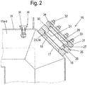
- Fig. 2 is a section of the buttering machine behind Fig. 1 in the region of a second sight glass 16 to the vacuum chamber 11 a and 11 b of the Fig. 1 shown.
- the construction of the first sight glass 15 may be designed analogously or identically to the construction of the second sight glass 16.
- the respective vacuum chamber 11a, 11b has an opening 17 in each case. Congruent with the opening 17, the vacuum chamber 11a, 11b each have a flange 18 which is fixed to the vacuum chamber 11a, b.
- the flange 18 also has an opening 19 which is contour-congruent with the opening 17 and is therefore arranged corresponding to the opening 17.
- an intermediate element 20 is arranged, which also has an opening 21. This opening 21 is designed congruent contour to the opening 17 and is therefore arranged corresponding to the opening 17.
- the intermediate element 20 has a centering projection 23, which engages in a geometrically corresponding recess 24 of the flange 18. Between the spigot 23 and the recess 24, a seal is arranged, which seals the openings 19, 21 against the environment.
- the intermediate element 20 of the second sight glass 16 has a connection 25 for a line or a hose 26. Furthermore, the intermediate element 20 of the second sight glass 16 has at least one 27 or more nozzle-like passages 27, which connects the connection 25 with the opening 21.
- the openings 21 of the three passages 27 are directed to the vacuum chamber side facing away from the intermediate element 20. Through the connection 25 and the nozzle-like passages 27, a fluid - such as steam - are passed through the intermediate member 20 into the opening 21.
- the vacuum chamber 11a, 11b (see Fig. 2 ) has a wall 35 which is provided with a passage 36. In the passage 36, a nozzle assembly 38 is used.
- a vacuum pump (not shown here) can be connected to the feedthrough 36 outside the vacuum chamber 11a, 11b, with which air and optionally steam can be sucked out of the vacuum chamber 11a, 11b.
- the nozzle assembly 38 is designed in the manner of a multiple nozzle ("spray ball-like"), the plurality of fine inlet openings with a small diameter within the vacuum chamber 11a, 11b, which open into a common channel of larger diameter, which passes through the wall 35.
- FIG. 3 and FIG. 4 in each case the intermediate element 20 with the nozzle-like passages 27 is shown.
- the here three nozzle-like passages 27 are preferably arranged at an angle ⁇ of 10 to 20 °, more preferably 15 ° perpendicular to the axis of the opening 21.
- the three passages are arranged in a plane parallel to the axis of the opening 21 preferably at an angle ⁇ of 20 to 60 °, more preferably of 30 ° to each other like a fan.
- the nozzle-like passages 27 have a diameter preferably between 1 and 5 mm, particularly preferably 1.5 mm.
- the intermediate element 20 of the first sight glass 15 can optionally also have a connection 25 and one or more nozzle-like passages 27, with which the viewing pane 29 of the first sight glass 15 can be acted upon by a fluid. This is advantageous, but not mandatory.
- the intermediate element 20 has a recess 28, in which the viewing window 29 is inserted. Between the lens 29 and the intermediate member 20, a seal 30 is arranged, which seals the opening 21 against the environment.
- the viewing window 29 and thus the second sight glass 16 has a device with which the viewing window 29 can be heated (not shown here).
- the heating device is in turn preferably in the viewing window 29 introduced heating element made of a material having a suitable electrical resistance, so that the viewing window 29 of the second sight glass 16 is electrically heated by the heating element.
- heaters are conceivable that work with a different mode of action.
- the heater it is again advantageously possible to automatically remove or clean during the butter production in the butter machine on the lens 29 of the second sight glass 16 forming butter deposits.
- the heat deposited on the lens 29 of the second sight glass 16 butter deposits are again melted with the heater so that the butter deposits from the window 29 of the second sight glass 16 can drain.
- the temperature which can be achieved during heating at the sight glass-here 16 - is preferably 40 to 90.degree. C., preferably 60.degree. A temperature above 90 ° C appears less advantageous, since evaporation of the water in the butter is not desirable.
- the viewing window 29 of the second sight glass 16 is screwed with a sight glass goggles 31 by means of several screws 32 on the intermediate member 20 and pressed.
- the sight glass goggles 31 has for this purpose a recess 33 into which the viewing window 29 engages.
- a seal 34 is arranged, which seals the visor 29 against the environment.
- the viewing window 29 of the second sight glass 16 is additionally provided with a fluid, such as e.g. Steam acted upon.
- a fluid such as e.g. Steam acted upon.
- films formed in addition to the butter deposits can also be supplemented by butter additives, such as e.g. Additional flavorings, water or whey, acid concentrates and brine on the viewing window 29 of the second sight glass 16 advantageously automatically reliably clean.
- butter additives such as e.g. Additional flavorings, water or whey, acid concentrates and brine on the viewing window 29 of the second sight glass 16 advantageously automatically reliably clean.
Abstract
Eine Vorrichtung zum Herstellen von Butter die einen Einlauf (1), einen Butterungszylinder (2) mit einem drehbaren Schläger (3), eine Nachbutterungstrommel (5) mit einer Haube (6), mindestens eine Abpresserstufe mit einem Abpresser (8) sowie wenigstens ein Schauglas mit einer Sichtscheibe aufweist, zeichnet sich dadurch aus, dass die Sichtscheibe eine Heizeinrichtung aufweist.An apparatus for producing butter comprising an inlet (1), a buttering cylinder (2) with a rotatable racket (3), a Nachbutterungstrommel (5) with a hood (6), at least one Abpresserstufe with a presser (8) and at least one Sight glass having a viewing window, characterized in that the viewing window has a heating device.
Description
Die Erfindung beschreibt eine Vorrichtung zum Herstellen von Butter nach dem Oberbegriff des Anspruchs 1.The invention describes an apparatus for producing butter according to the preamble of claim 1.
Im Bereich der industriellen Butterungsverfahren hat sich die kontinuierliche Butterung mit einer Maschine bzw. Vorrichtung zum Herstellen von Butter nach Dr. Fritz aus dem Jahr 1941 durchgesetzt. Durch diese Maschine und das entsprechende Verfahren wird eine gute und gleichmäßige Qualität der Butter bei geringen Fettverlusten sichergestellt.In the field of industrial buttering processes, the continuous buttering with a machine or device for producing butter according to Dr. med. Fritz from 1941 enforced. By this machine and the corresponding procedure a good and uniform quality of the butter with small fat losses is ensured.
Aufgrund des Fritz/Eisenreich - Verfahrens konnten die Arbeitsschritte der Schlagsahnebildung, der anschließenden Butterkornbildung, des Abtrennens von Buttermilch und des Knetens der Butter automatisiert werden. Dabei wurden die Prozesse der Butterkornbildung von Butterungstrommeln und des Knetens des erhaltenen Butterzwischenproduktes von Abpressern mit motorischen Schneckenantrieben gewährleistet.Due to the Fritz / Eisenreich method, the steps of whipping cream formation, the subsequent formation of buttercorn, the separation of buttermilk and the kneading of the butter could be automated. The processes of butter-grain formation of buttering drums and kneading of the obtained butter intermediate of pushers with motor screw drives were ensured.
Eine beispielhafte gattungsgemäße Vorrichtung ist in der
Zur visuellen Kontrolle des Verfahrensablaufs weisen solche Vorrichtungen Schaugläser im Bereich einer Nachbutterungstrommel und/oder im Bereich einer Vakuumiereinrichtung in einem Abpresser auf. Auf Grund der visuellen Kontrolle des Verfahrensablaufs werden Verfahrensparameter der Butterherstellung, wie z.B. die Drehzahl eines sogenannten Schlägers oder Einstellungen am Abpresser während des Verfahrensablaufs je nach Bedarf verändert.For visual control of the process sequence, such devices have sight glasses in the region of a post-treatment drum and / or in the region of a vacuum-forming device in a press-off device. Due to the visual control of the process, process parameters of butter production, e.g. changed the speed of a so-called racket or settings on the presser during the procedure as needed.
Derartige Verfahren und Vorrichtungen haben sich in der Praxis gut bewährt. Jedoch kommt es bei solchen Vorrichtungen zu Beeinträchtigungen der Beobachtbarkeit des Verfahrensablaufs durch Butterablagerung an den Schaugläsern.Such methods and devices have been well proven in practice. However, in such devices impairment of observability of the process by butter deposits on the sight glasses occurs.
Durch die Butterablagerungen auf den Schaugläsern ist eine visuelle Kontrolle des Verfahrensablaufs der Butterherstellung nur sehr eingeschränkt oder gar nicht mehr möglich.Due to the butter deposits on the sight glasses, a visual control of the process of butter production is only very limited or no longer possible.
Die Erfindung setzt daher bei der Aufgabe an, die Beobachtbarkeit der Butterherstellung mit den gattungsgemäßen Vorrichtungen zu verbessern.The invention therefore sets in the task of improving the observability of butter production with the generic devices.
Die Erfindung löst die Aufgabe durch eine Vorrichtung mit den Merkmalen des Anspruchs 1. Durch die Heizeinrichtung ist es vorteilhaft möglich, dass an der Sichtscheibe des Schauglases anhaftenden Butterablagerungen aufgeschmolzen werden, so dass sie von dem Schauglas abtropfen können. Dadurch wird Beobachtbarkeit des Butterungsprozesses verbessert.The invention solves the problem by a device having the features of claim 1. By the heater, it is advantageously possible that adhering to the viewing window of the sight glass butter deposits are melted so that they can drip from the sight glass. This improves the observability of the buttering process.
In einer bevorzugten Ausführungsform der Erfindung beruht die Heizeinrichtung auf einem elektrischen Wirkprinzip. Dadurch kann die Heizeinrichtung einfach und vorteilhaft in die Sichtscheibe des jeweiligen Schauglases integriert werden.In a preferred embodiment of the invention, the heating device is based on an electrical operating principle. As a result, the heating device can be easily and advantageously integrated into the viewing window of the respective sight glass.
In einer weiteren bevorzugten Ausführungsform ist wenigstens die Sichtscheibe des beheizbaren Schauglases ergänzend zur Reinigung mit einem Fluid beaufschlagbar. Dadurch können durch das Heizelement aufgeschmolzene Butterablagerungen auf der Sichtscheibe vorteilhaft zusätzlich von der Sichtscheibe gespült werden. Dadurch lassen sich auch zusätzlich zu den Butterablagerungen entstehenden Filme durch Butterzusatzstoffe, wie z.B. zusätzliche Geschmacksstoffe, Wasser oder Molke, Säurekonzentrate und Salzlake auf der Sichtscheibe vorteilhaft zuverlässig automatisch abreinigen.In a further preferred embodiment, at least the viewing window of the heated sight glass can be acted upon in addition to the cleaning with a fluid. As a result, by the heating element melted melted butter deposits on the lens can be additionally flushed from the lens. As a result, films formed in addition to the butter deposits can also be supplemented by butter additives, such as e.g. Advantageously automatically clean off additional flavors, water or whey, acid concentrates and brine on the lens.
Vorteilhafterweise wird als Fluid Dampf verwendet, wobei das anfallende Kondensat durch Einrichtungen an den Schaugläsern auffangbar oder mit einer Pumpe absaugbar ist und so wieder ganz oder teilweise aus dem Butterungsprozess herausbringbar ist.Advantageously, steam is used as the fluid, wherein the resulting condensate is trappable by means of the sight glasses or sucked by a pump and so again completely or partially herausbringbar from the Butterungsprozess.
In einer weiteren Ausführungsform der Erfindung wird das Fluid durch einen oder mehrere düsenartige Durchlässe auf die Sichtscheibe wenigstens eines Schauglas geleitet. Dadurch ist eine einfache und wirksame und damit vorteilhafte Aufbringung des Fluids auf die Sichtscheibe gegeben.In a further embodiment of the invention, the fluid is passed through one or more nozzle-like passages on the viewing window of at least one sight glass. As a result, a simple and effective and thus advantageous application of the fluid is given to the lens.
Vorteilhaft ist, wenn ein Zwischenelement den einen oder die mehreren düsenartigen Durchlässe aufweist. Dadurch kann das Fluid gezielt und damit vorteilhaft auf die Sichtscheibe des Schauglases geleitet werden.It is advantageous if an intermediate element has the one or more nozzle-like passages. As a result, the fluid can be directed specifically and thus advantageously on the viewing window of the sight glass.
In einer weiteren Ausführungsvariante der Erfindung ist der eine oder sind die mehreren düsenartigen Durchlässe bevorzugt unter einem Winkel β von 10 bis 20°, besonders bevorzugt 15° senkrecht zu einer Achse einer Öffnung des Zwischenelementes angeordnet. Durch die vorteilhafte Winkellage der düsenartigen Durchlässe ist eine sichere und damit vorteilhafte Abreinigung der Sichtscheibe des Schauglases realisierbar.In a further embodiment variant of the invention, the one or the plurality of nozzle-like passages is preferably arranged at an angle β of 10 to 20 °, particularly preferably 15 °, perpendicular to an axis of an opening of the intermediate element. Due to the advantageous angular position of the nozzle-like passages, a safe and thus advantageous cleaning of the viewing window of the sight glass can be realized.
Nach einer weiteren Ausführungsform der Erfindung sind die mehreren düsenartigen Durchlässe in einer parallelen Ebene senkrecht zur Achse der Öffnung angeordnet, und zwar bevorzugt unter einem Winkel α von 20 bis 60°, besonders bevorzugt von 30° zueinander (fächerartig) angeordnet. Dadurch wird vorteilhaft sichergestellt, dass die Sichtscheibe besonders gut abgereinigt wird.According to a further embodiment of the invention, the plurality of nozzle-like passages are arranged in a parallel plane perpendicular to the axis of the opening, and preferably at an angle α of 20 to 60 °, more preferably of 30 ° to each other (fan-like) arranged. This advantageously ensures that the viewing window is cleaned particularly well.
Weitere vorteilhafte Ausgestaltungen der Erfindung sind den übrigen Unteransprüchen zu entnehmen.Further advantageous embodiments of the invention can be found in the remaining subclaims.
Ein Ausführungsbeispiel der Erfindung wird anhand der beigefügten Zeichnungen naher erläutert. In der Zeichnung zeigen:
- Fig. 1:
- eine schematische Darstellung einer erfindungsgemäßen Vorrichtung zum Herstellen von Butter;
- Fig. 2:
- ein Ausschnitt der Vorrichtung nach
Fig. 1 im Bereich eines Schauglases an einer Vakuumkammer eines Abpressers der Vorrichtung, - Fig. 3:
- eine Vorderansicht eines Schauglases;
- Fig. 4:
- eine Schnittansicht des Schauglases nach
Fig. 3 ; - Fig. 5:
- eine weitere Schnittansicht des Schauglases nach
Fig. 3 .
- Fig. 1:
- a schematic representation of an apparatus according to the invention for producing butter;
- Fig. 2:
- a section of the device after
Fig. 1 in the region of a sight glass on a vacuum chamber of a press-off device of the device, - 3:
- a front view of a sight glass;
- 4:
- a sectional view of the sight glass after
Fig. 3 ; - Fig. 5:
- another sectional view of the sight glass after
Fig. 3 ,
In einer Kühlsektion 4 erhält das Butterkorn eine härtere Konsistenz und lässt sich anschließend besser bearbeiten.In a cooling section 4, the butter kernel gets a harder consistency and can then be processed better.
In einer Nachbutterungstrommel 5 wird im Nachbutterungsprozess die optimale Butterkorngröße eingestellt.In a
Das Butterkorn wird anschließend über eine Haube 6 mit einem Zuführschacht 7 in eine erste Abpresserstufe mit einem Abpresser 8 überführt.The buttercorn is then transferred via a
Der Abpresser 8 wandelt das Butterkorn in eine homogene "Wasser in Öl Emulsion" um und befreit gleichzeitig das entstandene Butterzwischenprodukt von Buttermilchresten, welche anschließend abgeführt werden.The Abpresser 8 converts the buttercorn into a homogeneous "water in oil emulsion" and at the same time frees the resulting Butterzwischenprodukt of Buttermilchresten, which are subsequently removed.
Im Abpresser 8 sind hier beispielhaft zwei Mischsektionen 9a und 9b angeordnet, in welchen jeweils eine Teilmasse des Butterzwischenproduktes getrennt bearbeitet werden kann. Somit können verschiedene Butterqualitäten des Endproduktes in kontinuierlicher Herstellung erreicht werden.In the presser 8, two
Die Mischsektionen 9a oder 9b weisen dabei zumindest je einen Dosieranschluss 10a oder 10b auf, um zusätzliche Geschmacksstoffe, Wasser oder Molke, Säurekonzentrate und Salzlake zu dem Butterzwischenprodukt in vorbestimmter Menge zuzufügen.The
Das Butterzwischenprodukt gelangt im Anschluss von jeweils einer Mischsektion 9a oder 9b über eine Vakuumkammer 11a oder 11b hier in eine zweite Abpresserstufe, bestehend aus zwei Abpressern 12a, 12b. Die zwei Abpresser der zweiten Stufe sind räumlich getrennt, wobei je ein Abpresser 12a oder 12b eine Teilmasse des Butterzwischenproduktes je einer Mischsektion 9a oder 9b bearbeitet.The butter intermediate passes in the connection of each of a
In der jeweiligen Vakuumkammer 11a, 11b der ersten Abpresserstufe wird der jeweiligen Teilmasse des Butterzwischenproduktes Luft entzogen, um deren Haltbarkeit zu erhöhen und um eine Schichtenbildung durch Lufteinschluss zu verhindern. Die Vakuumkammern 11a, 11b weisen jeweils ein zweites Schauglas 16 auf, durch das der Prozess in der Vakuumkammer beobachtbar ist.In the
Die Abpresser 12a, 12b der zweiten Abpresserstufe sorgen zusammen mit den sich daran anschließende Mischzonen 13a, 13b für eine gleichmäßige Verteilung des Wassergehaltes und eine Optimierung des Wassergehaltes in den beiden Teilmassen des Butterzwischenproduktes.The
Die Butterendprodukte verlassen die Butterungsmaschine hier über Ausläufe, welche in der vorliegenden Zeichnung durch zwei Mundstücke 14a und 14b und eine Austragspumpe 22 dargestellt sind.The Butterendprodukte leave the butter machine here via spouts, which are shown in the present drawing by two
Wie aus dem
Das erste Schauglas 15 weist eine Einrichtung auf, mit der eine Sichtscheibe des ersten Schauglases 15 beheizbar ist (letzteres hier nicht dargestellt). Bei der Heizeinrichtung handelt es sich z.B. um in die Sichtscheibe des ersten Schauglases eingebrachte Heizleiter aus einem Werkstoff mit einem geeigneten elektrischen Widerstand, so dass die Sichtscheibe durch die Heizleiter elektrisch beheizbar ist. Alternativ sind auch Heizeinrichtungen denkbar, die mit einem anderen Wirkprinzip arbeiten.The
Durch die Heizeinrichtung ist es vorteilhaft möglich, dass sich durch die Produktion in der Buttermaschine an dem ersten Schauglas 15 bildende Butterablagerungen automatisch entfernbar sind bzw. das erste Schauglas 15 abreinigbar ist. Dazu wird die Heizeinrichtung der Sichtscheibe des ersten Schauglases 15 eingeschaltet. Infolge der Wärmeentwicklung werden die an der Sichtscheibe des ersten Schauglases 15 anhaftenden Butterablagerungen aufgeschmolzen, so dass die Butterablagerungen von der Sichtscheibe des ersten Schauglases 15 in den laufenden Butterungsprozess abtropfen können. Dadurch wird vorteilhaft die einschränkungsfreie Beobachtung des Nachbutterungsprozess in der Nachbutterungstrommel 5 ermöglicht.By means of the heating device, it is advantageously possible for butter deposits forming on the
In
Im Folgenden wird das zweite Schauglas 16 beschrieben. Der Aufbau des ersten Schauglases 15 kann analog oder identisch zum Aufbau des zweiten Schauglases 16 gestaltet sein.Hereinafter, the
Die jeweilige Vakuumkammer 11a, 11b weist jeweils eine Öffnung 17 auf. Kongruent zu der Öffnung 17 weist die Vakuumkammer 11a, 11b jeweils einen Flansch 18 auf, der an der Vakuumkammer 11a, b befestigt ist.The
Der Flansch 18 weist ebenfalls eine Öffnung 19 auf, die konturkongruent zur Öffnung 17 gestaltet ist und deshalb korrespondierend zur Öffnung 17 angeordnet ist. Auf dem Flansch 18 ist ein Zwischenelement 20 angeordnet, das ebenfalls eine Öffnung 21 aufweist. Auch diese Öffnung 21 ist konturkongruent zur Öffnung 17 gestaltet und ist deshalb korrespondierend zur Öffnung 17 angeordnet.The
Es ergibt sich dadurch also eine durchgehende Öffnung mit hier gleichbleibendem Querschnitt, welche die Vakuumkammer 11a, bzw. 11b, den Flansch 18 und das Zwischenelement 20 durchgreift und die jeweils die Teilöffnungen 17, 19, 21 aufweist.This results in a continuous opening with a constant cross-section here, which passes through the
Das Zwischenelement 20 weist einen Zentrieransatz 23 auf, der in eine geometrisch korrespondierende Vertiefung 24 des Flansches 18 eingreift. Zwischen dem Zentrieransatz 23 und der Vertiefung 24 ist eine Dichtung angeordnet, die die Öffnungen 19, 21 gegen die Umgebung hin abdichtet.The
Das Zwischenelement 20 des zweiten Schauglases 16 weist einen Anschluss 25 für eine Leitung oder einen Schlauch 26 auf. Ferner weist das Zwischenelement 20 des zweiten Schauglases 16 wenigstens einen 27 oder mehrere düsenartigen Durchlässe 27 auf, der den Anschluss 25 mit der Öffnung 21 verbindet. Die Öffnungen 21 der hier drei Durchlässe 27 (siehe
Die Vakuumkammer 11a, 11b (siehe
Die Düsenanordnung 38 ist nach Art einer Mehrfachdüse ("sprayballartig") ausgestaltet, die mehrere feine Eintrittsöffnungen mit einem kleinen Durchmesser innerhalb der Vakuumkammer 11a, 11b aufweist, die in einen gemeinsamen Kanal größeren Durchmessers münden, der die Wandung 35 durchsetzt.The
In
Das Zwischenelement 20 des ersten Schauglases 15 kann optional ebenfalls einen Anschluss 25 und einen oder mehreren düsenartige(n) Durchlässe 27 aufweisen, mit dem bzw. denen die Sichtscheibe 29 des ersten Schauglases 15 mit einem Fluid beaufschlagbar ist. Dies ist vorteilhaft, jedoch nicht zwingend.The
Das Zwischenelement 20 weist eine Vertiefung 28 auf, in die die Sichtscheibe 29 eingelegt ist. Zwischen der Sichtscheibe 29 und dem Zwischenelement 20 ist eine Dichtung 30 angeordnet, die die Öffnung 21 gegen die Umgebung hin abdichtet.The
Die Sichtscheibe 29 und damit das zweite Schauglas 16 weist eine Einrichtung auf, mit der die Sichtscheibe 29 beheizbar ist (hier nicht dargestellt). Bei der Heizeinrichtung handelt es sich wiederum vorzugsweise um in die Sichtscheibe 29 eingebrachte Heizleiter aus einem Werkstoff mit einem geeigneten elektrischen Widerstand, so dass die Sichtscheibe 29 des zweiten Schauglases 16 durch die Heizleiter elektrisch beheizbar ist. Alternativ sind auch Heizeinrichtungen denkbar, die mit einem anderen Wirkprinzip arbeiten. Durch die Heizeinrichtung ist es wiederum vorteilhaft möglich, sich während der Butterherstellung in der Buttermaschine an der Sichtscheibe 29 des zweiten Schauglases 16 bildende Butterablagerungen automatisch zu entfernen bzw. zu reinigen. Dazu werden wiederum mit der Heizeinrichtung die an der Sichtscheibe 29 des zweiten Schauglases 16 anhaftenden Butterablagerungen aufgeschmolzen, so dass die Butterablagerungen von der Sichtscheibe 29 des zweiten Schauglases 16 abtropfen können. Vorzugsweise beträgt die beim Beheizen am Schauglas - hier 16 - erreichbare Temperatur 40 bis 90°C, bevorzugt 60°C. Eine Temperatur über 90°C erscheint weniger vorteilhaft, da ein Verdampfen des Wassers in der Butter nicht erwünscht ist.The
Die Sichtscheibe 29 des zweiten Schauglases 16 wird mit einer Schauglasbrille 31 mittels mehrerer Schrauben 32 auf das Zwischenelement 20 geschraubt und gepresst. Die Schauglasbrille 31 weist dazu eine Vertiefung 33 auf, in die die Sichtscheibe 29 eingreift. Zwischen der Sichtscheibe 29 und der Schauglasbrille 31 ist eine Dichtung 34 angeordnet, die die Sichtscheibe 29 gegen die Umgebung hin abdichtet.The
Durch die düsenartigen Durchlässe 27 ist die Sichtscheibe 29 des zweiten Schauglases 16 zusätzlich mit einem Fluid, wie z.B. Dampf beaufschlagbar. Dadurch können durch das Heizelement aufgeschmolzene Butterablagerungen auf der Sichtscheibe 29 vorteilhaft zusätzlich von der Sichtscheibe 29 gespült werden.Through the nozzle-
Dadurch lassen sich auch zusätzlich zu den Butterablagerungen entstehenden Filme durch Butterzusatzstoffe, wie z.B. zusätzliche Geschmacksstoffe, Wasser oder Molke, Säurekonzentrate und Salzlake auf der Sichtscheibe 29 des zweiten Schauglases 16 vorteilhaft zuverlässig automatisch abreinigen.As a result, films formed in addition to the butter deposits can also be supplemented by butter additives, such as e.g. Additional flavorings, water or whey, acid concentrates and brine on the
Durch die Beheizbarkeit der Sichtscheibe 29 des zweiten Schauglases 16 mit dem Heizelement und die zusätzliche Möglichkeit zur Entfernbarkeit von hartnäckigen Filmen aus Butterzusatzstoffen auf der Sichtscheibe 29 des zweiten Schauglases 16 durch Beaufschlagung der Sichtscheibe 29 mit einem Fluid, wie z.B. Dampf wird vorteilhaft die einschränkungsfreie Beobachtung des Herstellens der Butter optimiert.By the heatability of the
- Einlaufenema
- 11
- ButterungszylinderChurning cylinder
- 22
- Schlägerbat
- 33
- Kühlsektioncooling section
- 44
- NachbutterungstrommelNachbutterungstrommel
- 55
- HaubeHood
- 66
- Zuführschachtfeed chute
- 77
- AbpresserTexturizer
- 88th
- Mischsektionmixing section
- 9a, 9b9a, 9b
- Dosieranschlussdosing connection
- 10a, 10b10a, 10b
- Vakuumkammervacuum chamber
- 11a, 11b11a, 11b
- AbpresserTexturizer
- 12a, 12b12a, 12b
- Mischzonemixing zone
- 13a, 13b13a, 13b
- Mundstückmouthpiece
- 14a, 14b14a, 14b
- Schauglassight glass
- 1515
- Schauglassight glass
- 1616
- Öffnungopening
- 1717
- Flanschflange
- 1818
- Öffnungopening
- 1919
- Zwischenelementintermediate element
- 2020
- Öffnungopening
- 2121
- Austragspumpedischarge pump
- 2222
- ZentrieransatzSpigot
- 2323
- Vertiefungdeepening
- 2424
- Anschlussconnection
- 2525
- Schlauchtube
- 2626
- Durchlasspassage
- 2727
- Vertiefungdeepening
- 2828
- SichtscheibeWindow
- 2929
- Dichtungpoetry
- 3030
- SchauglasbrilleSight glass spectacles
- 3131
- Schraubescrew
- 3232
- Vertiefungdeepening
- 3333
- Dichtungpoetry
- 3434
- Wandungwall
- 3535
- Durchführungexecution
- 3636
- Düsenanordnungnozzle assembly
- 3838
Claims (15)
Applications Claiming Priority (1)
| Application Number | Priority Date | Filing Date | Title |
|---|---|---|---|
| DE202016100892.1U DE202016100892U1 (en) | 2016-02-19 | 2016-02-19 | Device for producing butter |
Publications (1)
| Publication Number | Publication Date |
|---|---|
| EP3207792A1 true EP3207792A1 (en) | 2017-08-23 |
Family
ID=55531615
Family Applications (1)
| Application Number | Title | Priority Date | Filing Date |
|---|---|---|---|
| EP17154347.3A Withdrawn EP3207792A1 (en) | 2016-02-19 | 2017-02-02 | Device for producing butter |
Country Status (3)
| Country | Link |
|---|---|
| US (1) | US20170238500A1 (en) |
| EP (1) | EP3207792A1 (en) |
| DE (1) | DE202016100892U1 (en) |
Citations (3)
| Publication number | Priority date | Publication date | Assignee | Title |
|---|---|---|---|---|
| DE102005013157A1 (en) * | 2004-03-24 | 2005-12-15 | Westfaliasurge Gmbh | Automated system to detect cow udder inflammation samples first milk discharge for optical flake examination |
| DE102009044429A1 (en) | 2009-11-05 | 2011-05-12 | Gea Westfalia Separator Gmbh | Apparatus and method for producing a plurality of butters |
| WO2014204391A1 (en) * | 2013-06-18 | 2014-12-24 | Delaval Holding Ab | Method and apparatus for cleaning an optical detection device |
-
2016
- 2016-02-19 DE DE202016100892.1U patent/DE202016100892U1/en active Active
-
2017
- 2017-02-02 EP EP17154347.3A patent/EP3207792A1/en not_active Withdrawn
- 2017-02-16 US US15/434,128 patent/US20170238500A1/en not_active Abandoned
Patent Citations (3)
| Publication number | Priority date | Publication date | Assignee | Title |
|---|---|---|---|---|
| DE102005013157A1 (en) * | 2004-03-24 | 2005-12-15 | Westfaliasurge Gmbh | Automated system to detect cow udder inflammation samples first milk discharge for optical flake examination |
| DE102009044429A1 (en) | 2009-11-05 | 2011-05-12 | Gea Westfalia Separator Gmbh | Apparatus and method for producing a plurality of butters |
| WO2014204391A1 (en) * | 2013-06-18 | 2014-12-24 | Delaval Holding Ab | Method and apparatus for cleaning an optical detection device |
Also Published As
| Publication number | Publication date |
|---|---|
| US20170238500A1 (en) | 2017-08-24 |
| DE202016100892U1 (en) | 2016-03-02 |
Similar Documents
| Publication | Publication Date | Title |
|---|---|---|
| DE102004041770A1 (en) | Device and method for microparticulation of filtration retentates | |
| DE102011086981A1 (en) | Single-screw extruder and method for producing a plasticized food product | |
| DE4107562A1 (en) | ULTRASONIC TEST SYSTEM | |
| AT516379B1 (en) | Filter device and method | |
| DE3714778C2 (en) | Method and device for continuously melting a gelled substance | |
| EP2921279B1 (en) | Device and method for homogenising plastic melts | |
| EP3207792A1 (en) | Device for producing butter | |
| EP2470004B1 (en) | Method for controlling and monitoring an automatized buttermaking process | |
| EP2946904B1 (en) | Device and method for degassing material to be processed | |
| DE19533693A1 (en) | Mixer kneader | |
| DE102012220991A1 (en) | Device for emulsifying a mixture of air, steam and milk | |
| EP3011246A1 (en) | Method and injector for introducing a vaporous heat carrier into a liquid product | |
| EP3536165B1 (en) | Thawing method for food | |
| EP3520887B1 (en) | Device for sequentially introducing additives in a polymer granulate and use of the device | |
| DE927006C (en) | Method and device for the production of a finely machined chocolate mass | |
| DE102011055008B4 (en) | Device for closing and separating sausages from a sausage strand and method for closing and separating sausages from a sausage strand | |
| DE1751728A1 (en) | Heat exchanger for the treatment of highly viscous liquids, preferably solutions of viscose | |
| DE2449787C2 (en) | Screw machine for degassing polymer melts and / or polymer solutions | |
| EP3222148B1 (en) | Tempering module | |
| DE102009055783A1 (en) | Optimization of a buttering process with small feed quantities of cream | |
| DE102016109678B4 (en) | Device for making butter | |
| DE60109143T2 (en) | Variable tilt device for refining food | |
| DE10329177A1 (en) | Temperature treatment process for chocolate mass, branches off side stream and returns it to main flow a different location in the process | |
| DE102004034798B4 (en) | Stirring system for glass melts | |
| DE102011117195A1 (en) | Method for optimizing an automated buttering process |
Legal Events
| Date | Code | Title | Description |
|---|---|---|---|
| PUAI | Public reference made under article 153(3) epc to a published international application that has entered the european phase |
Free format text: ORIGINAL CODE: 0009012 |
|
| AK | Designated contracting states |
Kind code of ref document: A1 Designated state(s): AL AT BE BG CH CY CZ DE DK EE ES FI FR GB GR HR HU IE IS IT LI LT LU LV MC MK MT NL NO PL PT RO RS SE SI SK SM TR |
|
| AX | Request for extension of the european patent |
Extension state: BA ME |
|
| 17P | Request for examination filed |
Effective date: 20180213 |
|
| RBV | Designated contracting states (corrected) |
Designated state(s): AL AT BE BG CH CY CZ DE DK EE ES FI FR GB GR HR HU IE IS IT LI LT LU LV MC MK MT NL NO PL PT RO RS SE SI SK SM TR |
|
| 17Q | First examination report despatched |
Effective date: 20191114 |
|
| STAA | Information on the status of an ep patent application or granted ep patent |
Free format text: STATUS: THE APPLICATION HAS BEEN WITHDRAWN |
|
| 18W | Application withdrawn |
Effective date: 20200305 |