EP3207699B1 - Systeme und verfahren zur verarbeitung eines blocks eines digitalbildes - Google Patents
Systeme und verfahren zur verarbeitung eines blocks eines digitalbildes Download PDFInfo
- Publication number
- EP3207699B1 EP3207699B1 EP14798877.8A EP14798877A EP3207699B1 EP 3207699 B1 EP3207699 B1 EP 3207699B1 EP 14798877 A EP14798877 A EP 14798877A EP 3207699 B1 EP3207699 B1 EP 3207699B1
- Authority
- EP
- European Patent Office
- Prior art keywords
- block
- rotational symmetry
- mask
- blocks
- pair
- Prior art date
- Legal status (The legal status is an assumption and is not a legal conclusion. Google has not performed a legal analysis and makes no representation as to the accuracy of the status listed.)
- Active
Links
- 238000000034 method Methods 0.000 title claims description 99
- 238000012545 processing Methods 0.000 title description 25
- 238000007906 compression Methods 0.000 claims description 75
- 230000006835 compression Effects 0.000 claims description 74
- 230000000295 complement effect Effects 0.000 claims description 47
- 230000009466 transformation Effects 0.000 claims description 21
- 230000008569 process Effects 0.000 claims description 19
- 230000002123 temporal effect Effects 0.000 claims description 13
- 238000013139 quantization Methods 0.000 claims description 9
- 238000004590 computer program Methods 0.000 claims description 5
- 230000033001 locomotion Effects 0.000 claims description 4
- 230000006870 function Effects 0.000 description 25
- 230000015654 memory Effects 0.000 description 25
- 238000010586 diagram Methods 0.000 description 23
- 238000003860 storage Methods 0.000 description 23
- 230000005540 biological transmission Effects 0.000 description 10
- 238000004364 calculation method Methods 0.000 description 10
- 230000006872 improvement Effects 0.000 description 8
- 238000007781 pre-processing Methods 0.000 description 8
- 230000009467 reduction Effects 0.000 description 7
- 239000011159 matrix material Substances 0.000 description 6
- 230000000007 visual effect Effects 0.000 description 6
- 238000005192 partition Methods 0.000 description 5
- 238000004891 communication Methods 0.000 description 4
- 230000001419 dependent effect Effects 0.000 description 4
- 230000006837 decompression Effects 0.000 description 3
- 238000005516 engineering process Methods 0.000 description 3
- 238000002474 experimental method Methods 0.000 description 3
- 239000000463 material Substances 0.000 description 3
- 238000010561 standard procedure Methods 0.000 description 3
- 238000012549 training Methods 0.000 description 3
- 238000003491 array Methods 0.000 description 2
- 238000010276 construction Methods 0.000 description 2
- 238000003708 edge detection Methods 0.000 description 2
- 230000010354 integration Effects 0.000 description 2
- 230000003287 optical effect Effects 0.000 description 2
- 230000001902 propagating effect Effects 0.000 description 2
- 230000011664 signaling Effects 0.000 description 2
- 238000000638 solvent extraction Methods 0.000 description 2
- RYGMFSIKBFXOCR-UHFFFAOYSA-N Copper Chemical compound [Cu] RYGMFSIKBFXOCR-UHFFFAOYSA-N 0.000 description 1
- 241000023320 Luma <angiosperm> Species 0.000 description 1
- 101150114886 NECTIN1 gene Proteins 0.000 description 1
- 102100023064 Nectin-1 Human genes 0.000 description 1
- 230000003044 adaptive effect Effects 0.000 description 1
- 238000004458 analytical method Methods 0.000 description 1
- 239000003086 colorant Substances 0.000 description 1
- 229910052802 copper Inorganic materials 0.000 description 1
- 239000010949 copper Substances 0.000 description 1
- 238000013144 data compression Methods 0.000 description 1
- 238000009826 distribution Methods 0.000 description 1
- 239000000835 fiber Substances 0.000 description 1
- 238000003709 image segmentation Methods 0.000 description 1
- 238000004519 manufacturing process Methods 0.000 description 1
- 238000013507 mapping Methods 0.000 description 1
- OSWPMRLSEDHDFF-UHFFFAOYSA-N methyl salicylate Chemical compound COC(=O)C1=CC=CC=C1O OSWPMRLSEDHDFF-UHFFFAOYSA-N 0.000 description 1
- 238000012986 modification Methods 0.000 description 1
- 230000004048 modification Effects 0.000 description 1
- 230000037361 pathway Effects 0.000 description 1
- 230000002441 reversible effect Effects 0.000 description 1
- 238000005070 sampling Methods 0.000 description 1
- 239000004065 semiconductor Substances 0.000 description 1
- 238000000926 separation method Methods 0.000 description 1
- 230000003068 static effect Effects 0.000 description 1
- 238000012360 testing method Methods 0.000 description 1
- 238000011426 transformation method Methods 0.000 description 1
- 230000001131 transforming effect Effects 0.000 description 1
- 238000011179 visual inspection Methods 0.000 description 1
Images


Classifications
-
- H—ELECTRICITY
- H04—ELECTRIC COMMUNICATION TECHNIQUE
- H04N—PICTORIAL COMMUNICATION, e.g. TELEVISION
- H04N19/00—Methods or arrangements for coding, decoding, compressing or decompressing digital video signals
- H04N19/10—Methods or arrangements for coding, decoding, compressing or decompressing digital video signals using adaptive coding
- H04N19/102—Methods or arrangements for coding, decoding, compressing or decompressing digital video signals using adaptive coding characterised by the element, parameter or selection affected or controlled by the adaptive coding
- H04N19/119—Adaptive subdivision aspects, e.g. subdivision of a picture into rectangular or non-rectangular coding blocks
-
- H—ELECTRICITY
- H04—ELECTRIC COMMUNICATION TECHNIQUE
- H04N—PICTORIAL COMMUNICATION, e.g. TELEVISION
- H04N19/00—Methods or arrangements for coding, decoding, compressing or decompressing digital video signals
- H04N19/10—Methods or arrangements for coding, decoding, compressing or decompressing digital video signals using adaptive coding
- H04N19/102—Methods or arrangements for coding, decoding, compressing or decompressing digital video signals using adaptive coding characterised by the element, parameter or selection affected or controlled by the adaptive coding
- H04N19/132—Sampling, masking or truncation of coding units, e.g. adaptive resampling, frame skipping, frame interpolation or high-frequency transform coefficient masking
-
- H—ELECTRICITY
- H04—ELECTRIC COMMUNICATION TECHNIQUE
- H04N—PICTORIAL COMMUNICATION, e.g. TELEVISION
- H04N19/00—Methods or arrangements for coding, decoding, compressing or decompressing digital video signals
- H04N19/10—Methods or arrangements for coding, decoding, compressing or decompressing digital video signals using adaptive coding
- H04N19/134—Methods or arrangements for coding, decoding, compressing or decompressing digital video signals using adaptive coding characterised by the element, parameter or criterion affecting or controlling the adaptive coding
- H04N19/136—Incoming video signal characteristics or properties
- H04N19/14—Coding unit complexity, e.g. amount of activity or edge presence estimation
-
- H—ELECTRICITY
- H04—ELECTRIC COMMUNICATION TECHNIQUE
- H04N—PICTORIAL COMMUNICATION, e.g. TELEVISION
- H04N19/00—Methods or arrangements for coding, decoding, compressing or decompressing digital video signals
- H04N19/10—Methods or arrangements for coding, decoding, compressing or decompressing digital video signals using adaptive coding
- H04N19/169—Methods or arrangements for coding, decoding, compressing or decompressing digital video signals using adaptive coding characterised by the coding unit, i.e. the structural portion or semantic portion of the video signal being the object or the subject of the adaptive coding
- H04N19/17—Methods or arrangements for coding, decoding, compressing or decompressing digital video signals using adaptive coding characterised by the coding unit, i.e. the structural portion or semantic portion of the video signal being the object or the subject of the adaptive coding the unit being an image region, e.g. an object
- H04N19/176—Methods or arrangements for coding, decoding, compressing or decompressing digital video signals using adaptive coding characterised by the coding unit, i.e. the structural portion or semantic portion of the video signal being the object or the subject of the adaptive coding the unit being an image region, e.g. an object the region being a block, e.g. a macroblock
-
- H—ELECTRICITY
- H04—ELECTRIC COMMUNICATION TECHNIQUE
- H04N—PICTORIAL COMMUNICATION, e.g. TELEVISION
- H04N19/00—Methods or arrangements for coding, decoding, compressing or decompressing digital video signals
- H04N19/10—Methods or arrangements for coding, decoding, compressing or decompressing digital video signals using adaptive coding
- H04N19/189—Methods or arrangements for coding, decoding, compressing or decompressing digital video signals using adaptive coding characterised by the adaptation method, adaptation tool or adaptation type used for the adaptive coding
- H04N19/196—Methods or arrangements for coding, decoding, compressing or decompressing digital video signals using adaptive coding characterised by the adaptation method, adaptation tool or adaptation type used for the adaptive coding being specially adapted for the computation of encoding parameters, e.g. by averaging previously computed encoding parameters
-
- H—ELECTRICITY
- H04—ELECTRIC COMMUNICATION TECHNIQUE
- H04N—PICTORIAL COMMUNICATION, e.g. TELEVISION
- H04N19/00—Methods or arrangements for coding, decoding, compressing or decompressing digital video signals
- H04N19/60—Methods or arrangements for coding, decoding, compressing or decompressing digital video signals using transform coding
- H04N19/61—Methods or arrangements for coding, decoding, compressing or decompressing digital video signals using transform coding in combination with predictive coding
-
- H—ELECTRICITY
- H04—ELECTRIC COMMUNICATION TECHNIQUE
- H04N—PICTORIAL COMMUNICATION, e.g. TELEVISION
- H04N19/00—Methods or arrangements for coding, decoding, compressing or decompressing digital video signals
- H04N19/10—Methods or arrangements for coding, decoding, compressing or decompressing digital video signals using adaptive coding
- H04N19/134—Methods or arrangements for coding, decoding, compressing or decompressing digital video signals using adaptive coding characterised by the element, parameter or criterion affecting or controlling the adaptive coding
- H04N19/146—Data rate or code amount at the encoder output
-
- H—ELECTRICITY
- H04—ELECTRIC COMMUNICATION TECHNIQUE
- H04N—PICTORIAL COMMUNICATION, e.g. TELEVISION
- H04N19/00—Methods or arrangements for coding, decoding, compressing or decompressing digital video signals
- H04N19/10—Methods or arrangements for coding, decoding, compressing or decompressing digital video signals using adaptive coding
- H04N19/134—Methods or arrangements for coding, decoding, compressing or decompressing digital video signals using adaptive coding characterised by the element, parameter or criterion affecting or controlling the adaptive coding
- H04N19/156—Availability of hardware or computational resources, e.g. encoding based on power-saving criteria
-
- H—ELECTRICITY
- H04—ELECTRIC COMMUNICATION TECHNIQUE
- H04N—PICTORIAL COMMUNICATION, e.g. TELEVISION
- H04N19/00—Methods or arrangements for coding, decoding, compressing or decompressing digital video signals
- H04N19/10—Methods or arrangements for coding, decoding, compressing or decompressing digital video signals using adaptive coding
- H04N19/134—Methods or arrangements for coding, decoding, compressing or decompressing digital video signals using adaptive coding characterised by the element, parameter or criterion affecting or controlling the adaptive coding
- H04N19/157—Assigned coding mode, i.e. the coding mode being predefined or preselected to be further used for selection of another element or parameter
Definitions
- the present invention in some embodiments thereof, relates to systems and methods for digital image and/or video compression and, more specifically, but not exclusively, to systems and methods for generating a set of transform coefficients for processing a block of a digital image.
- Digital images such as still images obtained by a digital camera, and digital video, require significant memory resources when stored in a non-compressed manner, represented by a full data set. Transmission of the full data set representing the digital images and/or video would require significant network resources, such as communication bandwidth. Video is especially problematic, as a single video may include thousands of individual frames. Storage and/or transmission of the full data set for each image may not be possible in many cases, or otherwise overwhelm processing and network resources.
- Video based applications running on mobile devices that rely on transmission of the video generate a large amount of network traffic, which is especially problematic for wireless networks.
- HEVC High Efficiency Video Coding
- WO 2011066672 A1 discloses partitioning an image block using a mask according to texture patterns.
- the object of the present invention is to provide an improved video compression technology.
- An aspect of some embodiments of the present invention relates to methods and/or systems for generating a set of transform coefficients for coding a block of a frame or portion thereof, the coding performed on two complementary portions obtained by splitting the block based on a certain selected rotational symmetry mask.
- the methods and/or systems reduce the size (e.g., number of bits) required to store and/or transmit the block, by improving the compression rate of the block, without a significant reduction in image quality.
- Any image quality reduction is within predefined acceptable limits and/or similar to image quality reduction using standard methods without the method described herein, for example, peak signal to noise ratio (PSNR) may be used as an objective measure to define image quality.
- PSNR peak signal to noise ratio
- the term frame or image sometimes refers to a portion of the frame or a portion of the image.
- the transform coefficients may be calculated for the entire frame (and/or image), and/or for a portion of the frame (and/or image), for example, the transform coefficients are calculated for slices and/or tiles, which are subparts of the frame, for example, as defined by the compression standard.
- the methods and/or systems include an encoder for encoding the block, by selecting a suitable rotational symmetry mask for the block, splitting the block to two complementary portions based on the mask, generating a pair of rotational symmetry blocks from each of the portions, and computing transform coefficient(s) for one or both of the rotational symmetry blocks.
- the methods and/or systems include a decoder for decoding the transform coefficients and re-constructing the block.
- the transform coefficients are decoded to re-construct the pair of rotational symmetry blocks.
- Each member of the pair is converted back (for example, based on inverse transform calculations) to the respective one of the two complementary portions.
- the two complementary portions are connected back together to form the block, guided by the rotational symmetry mask.
- the mask is selected to split the block to two complementary portions that are better compressed as compared to a compression of the whole block, or as compared to compression of a standard splitting method for the block (e.g., four squares, for example, as defined the High Efficiency Video Coding (HEVC) and/or H.265 standards).
- a standard splitting method for the block e.g., four squares, for example, as defined the High Efficiency Video Coding (HEVC) and/or H.265 standards.
- the mask is selected to split the block based on one or more visual features within the image of the block.
- the block may contain different types of content separated by the visual features, for example, a tilted line or edge depicted across the block.
- the mask may split the block substantially along the visual feature to generate two complementary portions that are each more homogenous to one another (i.e., each generally depicting one of the types of content) than would be formed when the block is split at a location other than the visual features, for example, into four equal blocks as specified by the HEVC standard.
- different masks are selected for different blocks.
- the masks may be independently selected for the blocks, for example, based on the content within the block. Compression of each block is improved by the customized mask selection.
- Each respective mask applied to each respective block is associated with the set of transform coefficients calculated for the respective block.
- the mask used for each block is transmitted along with the calculated transform coefficients, and/or a signal indicating which mask (e.g., out of a library of possible masks) is associated with the transform coefficients is transmitted.
- the mask has the property of being rotationally symmetric.
- the mask defines the split of the block into two complementary portions such that the shape of the block and the split are invariant under 180 degree rotational of the block with respect to the center of the block.
- the mask may be a binary mask (as described herein).
- the rotational symmetry allows for calculation of orthogonal transformation coefficients in two dimensions using a suitable orthogonal transformation method, for example, a 2D discrete cosine transform (DCT).
- DCT discrete cosine transform
- Each one of the two complementary portions retains the two dimensional topology of the original image content within the respective part of the block, allowing re-construction of the same image.
- the present invention may be a system, a method, and/or a computer program product.
- the computer program product may include a computer readable storage medium (or media) having computer readable program instructions thereon for causing a processor to carry out aspects of the present invention.
- the computer readable storage medium can be a tangible device that can retain and store instructions for use by an instruction execution device.
- the computer readable storage medium may be, for example, but is not limited to, an electronic storage device, a magnetic storage device, an optical storage device, an electromagnetic storage device, a semiconductor storage device, or any suitable combination of the foregoing.
- a non-exhaustive list of more specific examples of the computer readable storage medium includes the following: a portable computer diskette, a hard disk, a random access memory (RAM), a read-only memory (ROM), an erasable programmable read-only memory (EPROM or Flash memory), a static random access memory (SRAM), a portable compact disc read-only memory (CD-ROM), a digital versatile disk (DVD), a memory stick, a floppy disk, and any suitable combination of the foregoing.
- RAM random access memory
- ROM read-only memory
- EPROM or Flash memory erasable programmable read-only memory
- SRAM static random access memory
- CD-ROM compact disc read-only memory
- DVD digital versatile disk
- memory stick a floppy disk, and any suitable combination of the foregoing.
- a computer readable storage medium is not to be construed as being transitory signals per se, such as radio waves or other freely propagating electromagnetic waves, electromagnetic waves propagating through a waveguide or other transmission media (e.g., light pulses passing through a fiber-optic cable), or electrical signals transmitted through a wire.
- Computer readable program instructions described herein can be downloaded to respective computing/processing devices from a computer readable storage medium or to an external computer or external storage device via a network, for example, the Internet, a local area network, a wide area network and/or a wireless network.
- the network may comprise copper transmission cables, optical transmission fibers, wireless transmission, routers, firewalls, switches, gateway computers and/or edge servers.
- a network adapter card or network interface in each computing/processing device receives computer readable program instructions from the network and forwards the computer readable program instructions for storage in a computer readable storage medium within the respective computing/processing device.
- Computer readable program instructions for carrying out operations of the present invention may be assembler instructions, instruction-set-architecture (ISA) instructions, machine instructions, machine dependent instructions, microcode, firmware instructions, state-setting data, or either source code or object code written in any combination of one or more programming languages, including an object oriented programming language such as Smalltalk, C++ or the like, and conventional procedural programming languages, such as the "C" programming language or similar programming languages.
- the computer readable program instructions may execute entirely on the user's computer, partly on the user's computer, as a stand-alone software package, partly on the user's computer and partly on a remote computer or entirely on the remote computer or server.
- the remote computer may be connected to the user's computer through any type of network, including a local area network (LAN) or a wide area network (WAN), or the connection may be made to an external computer (for example, through the Internet using an Internet Service Provider).
- electronic circuitry including, for example, programmable logic circuitry, field-programmable gate arrays (FPGA), or programmable logic arrays (PLA) may execute the computer readable program instructions by utilizing state information of the computer readable program instructions to personalize the electronic circuitry, in order to perform aspects of the present invention.
- These computer readable program instructions may be provided to a processor of a general purpose computer, special purpose computer, or other programmable data processing apparatus to produce a machine, such that the instructions, which execute via the processor of the computer or other programmable data processing apparatus, create means for implementing the functions/acts specified in the flowchart and/or block diagram block or blocks.
- These computer readable program instructions may also be stored in a computer readable storage medium that can direct a computer, a programmable data processing apparatus, and/or other devices to function in a particular manner, such that the computer readable storage medium having instructions stored therein comprises an article of manufacture including instructions which implement aspects of the function/act specified in the flowchart and/or block diagram block or blocks.
- the computer readable program instructions may also be loaded onto a computer, other programmable data processing apparatus, or other device to cause a series of operational steps to be performed on the computer, other programmable apparatus or other device to produce a computer implemented process, such that the instructions which execute on the computer, other programmable apparatus, or other device implement the functions/acts specified in the flowchart and/or block diagram block or blocks.
- each block in the flowchart or block diagrams may represent a module, segment, or portion of instructions, which comprises one or more executable instructions for implementing the specified logical function(s).
- the functions noted in the block may occur out of the order noted in the figures.
- two blocks shown in succession may, in fact, be executed substantially concurrently, or the blocks may sometimes be executed in the reverse order, depending upon the functionality involved.
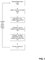
- FIG. 1 is a flowchart of a method for generating a set of transform coefficients for coding a block in a frame, in accordance with some embodiments of the present invention.
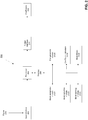
- FIG. 2 is a block diagram of the transform part of a media encoder 202 adapted to generate a set of transform coefficients for coding a block in a frame, in accordance with some embodiments of the present invention.
- the media encoder of FIG. 2 is configured to perform one or more blocks of the method of FIG. 1 .
- the method of FIG. 1 performed by the media encoder of FIG. 2 improve compression performance of digital images, in video and/or still format, without significantly lowering image quality, for example, as described with reference to FIGs.
- encoder 202 may serve as a coefficient decoder, in addition to, or instead of the described encoding functions.
- the decoding functions are based on the described encoding functions, but are omitted for clarity and brevity.
- media encoder 202 is described with reference to elements and/or methods for calculation of the transform coefficients (as described herein).
- Media encoder 202 may include and/or be in communication with other encoding components, for example, image encoder/decoder 1004 of FIG. 10 .
- Media encoder 202 includes one or more processors 204 in communication with one or more memories 206 (or other types of computer readable storage media) storing program instructions for execution by processors 204.
- Memory 206 may store data for use during processing, as described herein.
- Media encoder 202 may be implemented as software modules implemented within existing image compression software programs, as a chip that is integrated with existing hardware for image compression, a separate box that plugs into existing devices to improve image compression, or any combinations thereof.
- Processors 204 may perform the steps of the method based on parallel processing techniques, a single processor may be used, and/or processor(s) may be remotely located. Parallel processing may be used for the various candidate masks in the predefined set of rotational symmetry masks to select the best mask for splitting the block.
- One or more of memories 206 may be remotely located.
- Media encoder 202 improves system performance by improving efficiency and/or reducing resource requirements (e.g., memory and/or processor) for compression of images and/or video.
- resource requirements e.g., memory and/or processor
- a frame and/or block is received.
- Media encoder 202 is coupled to an input data interface 208 adapted to receive a frame 210 and/or block(s) of the frame.
- Frame 210 may be received as a still digital image, or as part of a video including multiple frames.
- inter-image compression techniques may be applied, as described herein.
- Media encoder 202 is adapted to designate a block partitioned in the frame.
- a block designator module 212A contains program instructions for media encoder 202 to perform the designation as described herein.
- the frame may be divided into multiple blocks, for example, based on a video and/or still image standard, for example HEVC, Moving Picture Experts Group (MPEG), and Joint Photographic Experts Group (JPEG).
- HEVC High Efficiency Video Coding
- MPEG Moving Picture Experts Group
- JPEG Joint Photographic Experts Group
- the blocks may have a standard size, for example, 64x64 pixels, 32x32 pixels, 16x16 pixels, 8x8 pixels, 4x4 pixels, or other sizes.
- the blocks may be squares (LxL pixels) or rectangles (MxN pixels).
- the blocks may represent luma and/or chroma data.
- a mask selector module 212B contains program instructions for media encoder 202 to perform the mask selection as described herein.
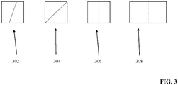
- FIG. 3 depicts schematic diagrams of some examples of rotational symmetry masks, in accordance with some embodiments of the present invention, for example, a right angle trapezoid 302, a right angle triangle 304, a rectangle 306 and a square 308.
- the media encoder is adapted to select a rotational symmetry mask for the designated block from multiple rotational symmetry masks which define multiple different rotational symmetries in a multi dimensional space having a size and a shape as the block.
- FIG. 4 is a schematic diagram depicting selection of a certain rotational symmetry mask 402 for a block 404 within a frame 406, in accordance with some embodiments of the present invention.
- Frame 406 contains an image of a house.
- Block 404 contains a portion of the roof of the house, and another portion of sky.
- Mask 402 is selected from a set of multiple available masks 410, based on certain compression preference measure (e.g., rate-distortion) and/or the visual feature boundary and/or edge that best separates the sky from the house.
- certain compression preference measure e.g., rate-distortion
- the rotational symmetry mask may be selected from multiple masks stored in a rotational symmetry masks library 212F, optionally stored on memory 206 and stored on another computer readable storage medium in communication with processor 204.
- Library 212F may store multiple different libraries of rotational symmetry masks. Each library may be based on a size and/or a shape of the block. For example, one library for masks of blocks of size 16x16 pixels, and another library for blocks of size 8x8 pixels.
- the different rotational symmetry masks are square masks (i.e., LxL pixels) having a size and a shape as the block.
- the different rotational symmetry masks are rectangular masks (i.e., MxN pixels) having a size and a shape as the block.
- the rotational symmetry mask is adapted to define a line which joins opposing edges of a rectangle or square, to split a corresponding rectangular or square block to two 2D mirrored complementary portions.
- Different lines may be defined based on the two dimensional mirroring condition.
- the line may be linear or other forms, for example, stairstep or other arbitrary shapes.
- the line may be tilted at any angle or part thereof from 0 to 359 degrees.
- the 2D mirror property provides efficient compression of the block.
- FIGs. 5A-5C are schematic diagrams depicting pixel 2D mirroring for defining the rotational symmetry masks, in accordance with some embodiments of the present invention.
- FIG. 5A depicts the general 2D mirror concept.
- a block 502 of size 8 pixels by 8 pixels is shown for example purposes. Regions A and region B are separated by a virtual line 504 positioned horizontally through the middle of block 502. Pixels having the same number in region A and region B are 2D mirrors of one another. Pixel 2D mirroring may be generalized for an MxN rectangle: when pixel (m, n) is in region A, then pixel (M-1-m, N-1-n) is in region B.
- the 2D mirror concept may be applied to other square or rectangular blocks of different sizes. It is understood that the 2D mirror concept may be depicted for other virtual lines drawn at different tilts, for example, vertically, where region A and B are defined and separated by a virtual line positioned vertically through the middle of block 502.
- FIGs. 5B and 5C Multiple different lines which join opposing edges of block 502 and cross the center point of block 502 are adapted to form a rotational symmetry mask library, as depicted in FIGs. 5B and 5C .
- Each individual line defines an individual mask.
- Each line splits block 502 into two complementary portions: region A and region B.
- the different rotational symmetry masks are defined by a respective matrix (e.g., each pixel position is represented by a location in the matrix).
- Each matrix defines a different separation of regions A and B, for example a line which joins opposing edges of the two dimensional space, to split the two dimensional space to two complementary portions.
- the rotational symmetry mask is defined to split the respective multi-dimensional space, for example, a plane to split a three dimensional space.
- FIG. 6A is an example of a library of masks for splitting a block of size 32x32 pixels.
- FIG. 6B is an example of a library of masks for splitting a block of size 16x16 pixels.
- FIG. 6C is an example of a library of masks for splitting a block of size 8x8.
- the rotational symmetry mask libraries of FIGs. 6A-6C are based on a tilted line, which splits the block into two trapezoidal regions, represented by a dark region 602 of the mask (e.g., blue) and a light region (604) of the mask (e.g., red).
- Each mark in the library has a slightly different tilt of the line.
- all the masks define all the different permutations of the tilted line within the block.
- masks 606A and 606B have parallel lines through them, representing removal of masks 606A and 606B from the set of 32 masks, to form the set of 30 masks based on the equation in the previous paragraph.
- the two masks are doubles of existing masks due to mirror symmetry, and therefore may be removed from the generated set.
- FIG. 6C two double masks are shown with parallel lines, representing the removal of the redundant masks from the set.
- each of the different rotational symmetry masks (which may be stored as one or more libraries) is mapped in a hierarchal arrangement.
- the hierarchal arrangement may reduce the processing time and/or resources to identify the best mask.
- Each library may be independently mapped, the masks of each respective library may be mapped in the hierarchal arrangement. Alternatively, one or more libraries are mapped together based on the same hierarchal arrangement. The masks within each library are mapped based on the same common hierarchal arrangement.
- the set of masks is divided into separate disjointed sections.
- the hierarchical arrangement may be according to an angle of the line in relation to an edge of the two dimensional space, for example, a hierarchal arrangement may map the lines of FIG. 6A-6C , for example, into group of 0-60 degrees, 61-120 degrees, and 121-180 degrees.
- the hierarchal arrangement may continue for mapping 181-240 degrees, 241-300 degrees, and 301-360 degrees, when the line is symmetrical and/or non-symmetrical.
- the hierarchal arrangement may be layered, for example, the group of 0-60 degrees is further sub-divided into the groups 0-15, 16-30, 31-45, and 46-60 degrees.
- FIG. 7 is a schematic diagram that graphically depicts the hierarchal arrangement, in accordance with some embodiments of the present invention.
- Divided circle 702 graphically depicts an example of a hierarchal arrangement for a mask library 706.
- Library 706 includes tilted line masks for a block of size 16x16, as described with reference to FIG. 6B .
- Circle 702 is divided into regions 704A-H, each representing 45 degrees of line tilt.
- the hierarchal arrangement is simplified due to the symmetrical nature of the tilted line masks, grouping together sectors 704A with 704E (shown as sectors 708C), 704B with 704F (shown as sectors 708B), 704C with 704G (shown as sectors 708A), and 704D with 704H (shown as sectors 708D).
- Each sector 708A-D includes 8 or 7 masks with line tilt angles falling within the respective angle range.
- the media encoder is adapted to select the rotational symmetry mask in an iterative mask selection of at least some of the different rotational symmetry masks in an order defined according to the hierarchal arrangement.
- the section may be selected based on a lowest cost calculated by a suitable function, for example, a minimum rate distortion measure.
- the mask within the selected section may be selected in a similar manner.
- the additional levels may be searched in an iterative manner until a mask is identified.
- FIG. 8 is a schematic depicting generation and/or representation of the rotational symmetry mask, in accordance with some embodiments of the present invention.
- a library of masks is generated, based on different permutations within the block containing the mask.
- mask generation for blocks of size LxL is described, which may be extended to the MxN case.
- the mask may be generated starting from the upper left corner, proceeding towards the center of the block.
- the combination of movements may be 2D mirrored to obtain the remaining mask pattern from the center of the block to the bottom right.
- the mask may be represented by a binary representation for each move. Each move is either horizontal (i.e., from left to right) or vertical (i.e., from top to bottom), represented by a 1 (e.g., one step to the right) or 0 (e.g., one step down).
- the binary mask representation may be transmitted as is, or be further compressed.
- the binary representation provides an efficient (i.e., in terms of processor and/or memory resource utilization) transmission of the mask, for example, from the encoder to the decoder.
- Each permutation in the set may be defined by a total of 2xL moves.
- Mask 802 is represented by binary pattern 804.
- Mask 806 is represented by binary pattern 808.
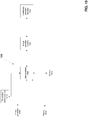
- FIG. 9 is a list (e.g., flowchart) of computerized methods for selecting a rotational symmetry mask and/or mask library for splitting the block, in accordance with some embodiments of the present invention.
- the mask and/or mask library may be generated (e.g., in advance and/or dynamically) based on the blocks, instead of and/or in addition to being selected.
- Media encoder 202 is adapted to perform one or more blocks of the method. One or more blocks of the method may be performed for mask selection. Blocks may be performed in any order and/or simultaneously.
- the one or more methods of selection described herein may be used as a basis for selection of a certain mask within a library of masks.
- the methods of selection may be used to first select a certain mask library out of multiple mask libraries, and/or a sub-set of masks out of the library.
- the certain mask may be selected out of the selected library and/or selected sub-set.
- the step-wise and/or hierarchical selection may reduce the search range, by reducing the size of the set for selection at each step, reducing resources and/or the computations for the selection.
- the selection of the mask from a library (or mask subset) instead of from a larger set of candidate masks reduces the number of encoded bits which are used to signal to a decoder the selected mask, and/or reduce the computation complexity and/or the memory sources and/or processor resources.
- the library and/or the mask is selected based on the size and/or shape of the block.
- the mask may be selected from within the selected library as described herein.
- the media encoder is adapted to select the rotational mask and/or rotational symmetry mask library from multiple rotational symmetry masks and/or mask libraries based on compression preference for any one or more of, but not limited to, the following list: block, slice, tile, frame, and sequence.
- the compression preference includes one or more parameters that define compression performance of the block when a certain mask is applied.
- the compression preference may be defined per mask and/or per mask library.
- the compression preference may be estimated, for example, based on previously collected statistical data for the mask and/or library.
- the compression preference may be calculated, for example, by applying one or more of the candidate masks to the block.
- Compression preferences may help in mask selection when compression parameters involve certain tradeoffs, for example, a decrease in size at the expense of decrease in quality.
- the compression preference is selected from one or more of the following, individually or in combination:
- the media encoder is adapted to automatically generate the rotational symmetry mask library according to a member of a group consisting of preferences for: a block compression complexity, a block compression size, and a block compression quality.
- the generated mask library has known compression preference criteria, which allows for easy and/or fast selection of the library.
- the number of masks within the generated library may be smaller than generating all possible permutations, as only masks satisfying the compression criteria are included.
- Each mask may be associated with the compression preference, for example, stored, matched, and/or tagged with the compression preference values.
- Each mask may be associated with one or more measures to calculate the compression complexity preference, the compression quality preference, and/or the compression size preference.
- each one of the different rotational symmetry masks is associated with an estimated complexity measure indicative of a computational complexity of applying the respective mask on an exemplary block having the size and the shape of the respective mask.
- Masks with lower estimated complexity measures are estimated to require fewer resources (e.g., processor and/or memory).
- Mask selection based on estimated outcome improves system efficiency and/or utilizes fewer resources.
- each one of the different rotational symmetry masks is associated with an estimated distortion measure indicative of a compression distortion level emanated from applying the respective mask on an exemplary block having the size and the shape of the respective mask.
- the estimated distortion measure helps in selecting the mask based on the lossy compression tradeoff, for example, to select the mask having visually indistinguishable compression distortion level that also produces higher compression of the image.
- Masks with lower estimated distortion measures are estimated to require fewer resources (e.g., processor and/or memory) while achieving the targeted compression distortion level.
- the media encoder is adapted to select a rotational symmetry mask based on compression preference for the block.
- the compression preference is selected from one or more of: a compression complexity preference, a compression quality preference, and a compression size preference.
- the mask selection is based on pre-processed video data that includes the received frame.
- the pre-processing of the video data may be performed by the media encoder, by another computer connected to the media encoder, or by another computer independent of the media encoder (e.g., remotely located).
- the pre-processed data may be transmitted to the media encoder independently of the frame, and/or with the frame (e.g., tagged to the frame).
- the pre-processing may be based on one or more identified features of the content of the frames of the video, for example, statistical distribution of pixel patterns, edges, pixel intensity, and pixel colors.
- the video data may be pre-classified based on the pre-processing results.
- the classification may be based on the identified features for allowing selection of the mask and/or mask library.
- the pre-classified video data improves system performance, as the masks may be selected more efficiently and/or using less resources based on the classification.
- the media encoder is adapted to select the rotational symmetry mask and/or mask library from multiple candidate rotational symmetry masks and/or mask libraries, based on the classification of the video data.
- the pre-processing may identify that the video contains frames having many straight lines, for example, images of houses, cars, or other artificial structures. The video data may be classified as containing straight lines. A mask library of straight lines (i.e., different angles) may be selected.
- the pre-processing may identify that the video contains frames having many curved lines, for example, images of tree, branches, and land terrain. The video data may be classified as containing curved lines.
- a mask library of curved lines i.e., stairstep lines based on discretization of curves may be selected).
- the pre-processing of content may provide information for encoding based on prediction, as described herein.
- the media encoder is adapted to automatically generate the rotational symmetry mask and/or mask library based on the preprocessed video data.
- the different rotational symmetry masks may be selected from the mask repository of different rotational symmetry masks according to one or more compression parameters: an outcome of the preprocessing for compression complexity preference, compression size preference and/or compression quality preference.
- the compression parameters may be pre-calculated from the video data.
- the pre-processing of the video data may improve performance of the encoder. Resource heavy computations may be performed in advance, instead of during the compression. Data serving as the basis for mask selection may be ready, to allow for faster mask selection during the block compression process, instead of performing the mask selection calculation during the compression process.
- the media encoder is adapted to select the rotational symmetry mask based on an outcome of transformation process and/or an estimation of an outcome of a transformation process applied on the at least one of the two complementary portions.
- Mask selection based on outcome and/or estimated outcome improves system efficiency and/or utilizes fewer resources.
- the outcome of transformation process may include the size (e.g., number and/or sum of absolute of transform coefficients which are above a certain threshold) of one or both of the complementary portions after the transformation process.
- the mask resulting in the smallest size of the portion after the transformation process may be selected.
- the size may be calculated for one or both portions, such as the sum of the size of both portions.
- the estimation of an outcome of a transformation process may include the Sum of Absolute Difference (SAD) of the residual data which is the input to the transformation process.
- SAD Sum of Absolute Difference
- the estimation of the outcome of a transformation process may include the sum of absolute of the first, the second, and/or the higher order derivatives along the horizontal and/or vertical directions of the residual data.
- the estimation may be based on values from previously encoded portions using the same mask.
- the outcome of the transformation process may be estimated by a known transformation process, for example, the transformation process(es) defined by the compression standard.
- the media encoder is adapted to select the rotational symmetry mask based on an outcome and/or an estimation of an outcome of a quantization process and/or an entropy coding process applied on the transform coefficients for at least one member of the pair of rotational symmetry blocks.
- the mask resulting in the smallest size of the portion after the quantization and/or entropy coding process may be selected, for example, the number of non-zero coefficients after quantization, and/or the size in generated bits, respectively.
- the size may be calculated for one or both portions, such as the sum of the size of both portions.
- the estimation may be based on values from previously quantized and/or entropy coded portions using the same mask.
- the media encoder is adapted to select the rotational symmetry mask according to a pattern of pixel values in the block.
- the pattern of pixel values may be extracted from the block, for example, by image segmentation methods, such as methods for locating boundaries and/or edges, for example based on intensity thresholding, edge detection, or other suitable methods.
- the pattern of pixel value may include the direction of an identified line within the block, and/or a pattern of the line (or curve).
- the extracted pixel pattern may be matched to a certain symmetry mask, for example, based on a lowest cost function to identify the mask with the most similar pattern to the extracted pixel pattern, such as matching masks that have the same direction and/or pattern as the identified line of the block. Selection based on the pattern of pixel values produces two complementary portions in which pixels within each respective portion are similar to one another, for example, similar intensity and/or color.
- the edge between the roof and the sky in block 404 is extracted based on an edge detection method.
- the detected edge is mapped to mask 402 based on a cost function.
- the pattern within mask 402 is the most similar pattern to the extracted edge, out of the mask library.
- the rotational symmetry mask is selected based on an estimated rate measure indicative of a number of bits transmitted when the certain rotational mask is applied to an exemplary block having the size and/or shape of the block being processed.
- a lower number of bits represents a more efficient compression with the certain mask.
- Each one of the different rotational symmetry masks is associated with the estimated rate measure indicative of the number of bits transmitted when the mask is applied on an exemplary block having the size and the shape.
- the rate measure may be stored with each mask, allowing for quick selection of the mask based on the estimated rate measure value.
- the rate measure may be calculated in advance for each mask, instead of being recalculated during run-time, thereby reducing the computations required for the selection.
- the rate measure may be calculated based on the exemplary block, which may be a predefined block based on an average (or other measure) of a previous sample of blocks.
- the exemplary block may be selected from a library of blocks based on a similarity to the block being processed, for example, based on a cost function.
- the media encoder is adapted to select the rotational symmetry mask based on a statistical classifier.
- the statistical classifier is generated by an analysis of a training set logging outcomes of applying at least some of the different rotational symmetry masks.
- the outcomes (which may be weighted) may include, for example, compression performance metrics (e.g., size, complexity, quality), processor resource utilization, and memory utilization.
- the statistical classifier may improve selection of the mask based on prediction of a result that includes multiple different desired outcomes.
- the training set may be obtained based on a history of actual frames that were processed by the system.
- the training set may be obtained based on a prediction of types of frames that will be processed, for example, a nature channel may train a classifier with nature videos.
- Outcomes of the classification may be used as inputs to further train and update the classifier.
- the statistical classifier may be trained based on supervised learning and/or unsupervised learning methods.
- the classifier may be applied to the block itself, to classify pixels within the block into one of two groups.
- the two groups may be divided based upon the rotational symmetry constraint of the rotationally symmetry mask.
- the mask is selected to match the arrangement of the two groups within the block.
- Each portion of the two complementary portions produces from the split of the block using the mask includes pixels from the respective group.
- the media encoder is adapted to select the rotational symmetry mask based on content extracted from spatial and/or temporal neighboring blocks of the block.
- the neighbors may be intra-image and/or inter-image blocks.
- Spatial blocks may be neighbors of the block in one or, several or all directions relative to the block.
- Temporal neighboring blocks may be from neighboring block in previous frames (e.g., earlier in time) and/or subsequent frames (e.g., later in time).
- Blocks may be direct neighbors, or located two or more blocks (or frames) away. Neighboring blocks containing similar pixel patterns used as predictors improve system performance and/or require fewer resources.
- the neighbors include previously processed blocks.
- the previously processed blocks may be used as predictors for selection of the mask for the block being currently processed.
- the selection of the rotational symmetry mask is performed based on information associated with spatial and/or temporal neighboring blocks of the block.
- the information associated with the spatial and/or temporal neighboring blocks is related to prediction.
- the information may include data to reduce the difference between the current block being processed and one or more of the neighbors, with redundant information being left out.
- the mask may be selected based on the difference data.
- the content extracted is according to a pattern of pixel values in the spatial and/or temporal neighboring blocks.
- the pixel pattern of the neighboring block may act as a predictor for selection of the mask in the currently block.
- the pixel pattern includes a boundary and/or edge between a roof and sky (as discussed with reference to FIG. 4 ). The edge between the roof and the sky continues across several neighboring blocks.
- Encoding based on predictors improves system efficiency and/or utilizes fewer resources.
- a block splitter module 212C contains program instructions for media encoder 202 to perform the block splitting as described herein.
- a pair of rotational symmetry blocks each having one of the two complementary portions is generated.
- a pair generator module 212D contains program instructions for media encoder 202 to perform the pair generation as described herein.
- the media encoder is adapted to generate each member of the pair of rotational symmetry blocks based on one of the two complementary portions and another portion added to form a block having a size and/or shape of the block.
- the added portion is a 2D mirror of the portion, which the rotational symmetry block is constructed from.
- the added portion is a 2D mirror of the portion from which the rotational symmetry block is constructed, but added with negative sign.
- the rotational symmetry block contains two anti-symmetric portions.
- the added portion includes padding with a predefined sequence, for example, all zeros.
- the added portion is generated based on a 180 degree rotation of the portion, which the rotational symmetry block is constructed from.
- the dimension of the added portion is based on the dimension of the complementary portion, for example, two dimensional.
- Each member of the generated pair of rotational symmetry blocks is represented by a matrix having values 2D mirrored around a main diagonal or other cut-line pattern based on the selected mask.
- one or more transform coefficients for one or both members of the pair of rotational symmetry blocks are computed.
- transform coefficients are calculated for each one of the rotational symmetry blocks.
- a coefficient calculation module 212E contains program instructions for media encoder 202 to perform the transform coefficient calculation as described herein.
- Calculation of the transform coefficients may be performed based on one or more standard based calculation methods, based on one or more encoding techniques, and/or based on proprietary methods.
- An example of an encoding technique includes a two dimensional discrete cosine transform (DCT), which may be calculated, for example, based on two separable fast DCTs applied along each dimension, for example, when the rotational symmetry blocks are represented as matrices, the 2D-DCT may be calculated along the rows and then the columns, or along the columns and then along the rows.
- DCT discrete cosine transform
- DST Discrete Sine Transform
- An example of a standard based encoding technique is the HEVC and/or H.265 standard for integer transform and/or inverse transform.
- an orthogonal transform set of coefficients is calculated for each one of the two complementary portions when the 2D mirrored portion is added with a negative sign (i.e. anti-symmetry).
- the set for the symmetrical and anti-symmetrical transform functions for calculation of the transform coefficients may be different.
- the respective symmetrical or anti-symmetrical transform function is used.
- the media encoder is adapted to code the transform coefficient(s) using one or more spatial predictors adapted to the respective portion of the rotational symmetry mask.
- the transform may be calculated for the predictive block, for a predictive vector, for a predictive error, and/or for a predictive residual.
- the prediction residual may be calculated for temporal and/or spatial blocks (i.e., inter and/or intra-image blocks) based on the difference between the portion in the rotational symmetry block being processed and the corresponding prediction block.
- the media encoder is adapted to code the transform coefficient(s) using one or more temporal predictors adapted to the respective portion of the rotational symmetry mask.
- the media encoder is adapted to code the transform coefficient(s) of each of the rotational symmetry blocks using a spatial predictor related to the respective corresponding portion.
- the media encoder is adapted to code the transform coefficient(s) of each of the pair of rotational symmetry blocks using a motion vector related to the respective corresponding portion. The motion vector may be used to calculate the temporal prediction.
- transform coefficients may be calculated based on one method for all transform coefficients, different methods for different transform coefficients (or sets of transform coefficients), and/or a combination of methods.
- the media encoder is adapted to code the transform coefficient(s) using an entropy context model adapted to the rotational symmetry mask.
- the entropy context model may be defined based on knowledge of the selected mask, to encode the transform coefficients with lossless data compression, for example, based on Huffman coding and/or arithmetic coding. As the entropy characteristics of the mask are known to the encoder in advance, a simpler code may be calculated.
- the entropy context model may be a proprietarily designed model, and/or a standard based model, for example, the Context Adaptive Binary Arithmetic Coding (CABAC) scheme, such as CABAC of H.265/HEVC, H.264/MPEG-4, or other standards.
- CABAC Context Adaptive Binary Arithmetic Coding
- the calculated transform coefficients are provided for further processing, storage and/or transmission.
- an output input interface 214 coupled to media encoder 202 is adapted to provide calculated transform coefficients 216, as described herein.
- blocks 102-112 are repeated for other blocks within the frame.
- Blocks 102-112 may be repeated for other frames. It is noted that blocks of a certain frame may be processed in parallel.
- FIG. 10 is a block diagram of an exemplary system 1000 for image compression and decompression incorporating a coefficient encoder/decoder 1002, in accordance with some embodiments of the present invention.
- Encoder/decoder 1002 may include the transform part of media encoder 202 as described with reference to FIG. 2 , a variant of encoder 202 (e.g., without processor 204, using the processor of another encoder/decoder), and/or another implementation of the method of FIG. 1 .
- Integration of encoder 1002 within system 1000 improves coding efficiency of the images and/or video, which improves overall performance of system 1000, for example, by improving compression performance, by reducing processor resource requirements, transmitter/receiver requirements, and/or memory requirements. Integration of encoder 1002 within system 1000 allows for higher image quality, higher image resolution and/or a larger number of images to be processed using the same resources.
- Coefficient encoder/decoder 1002 may be implemented within devices and/or systems associated with digital images and/or videos, for example, within a digital camera, within a television (e.g., high definition TV), within a digital camcorder, within a television broadcasting unit, within a Smartphone (or other mobile device), within a web-browser, within computer software to view and/or edit images and/or videos, within network devices (to improve network performance), within real-time conversation application (e.g., video chat, video conferencing, and telepresence systems).
- Implementation of encoder/decoder 1002 may improve performance of the device and/or system by reducing resource requirements (e.g., memory), for example, allowing more pictures and/or videos to be saved on a memory, allowing pictures and/or videos with higher quality and/or resolution to be saved, and lowering the size of each picture and/or video thus allowing for faster transmission of the picture and/or video over a network connection.
- resource requirements e.g., memory
- Encoder/decoder 1002 is integrated with an image encoder/decoder 1004 configured to encode and/or decode images and/or video by compression and/or decompression.
- Encoder/decoder 1004 may be based on a standard (e.g., HVEC, MPEG-4, JPEG) and/or based on one or more proprietary protocols.
- Coefficient encoder/decoder 1002 may be integrated with image encoder/decoder 1004, for example, as a chip or other hardware element(s) that is integrated within the hardware of encoder/decoder 1004, as a chip or other hardware element that plugs into encoder/decoder 1004, as external software modules, as software modules integrated within the code of encoder/decoder 1004, and/or combinations thereof.
- Image encoder/decoder 1004 may include encoding and/or decoding components, for example, one or more of: quantization (e.g., by a quantization module), coefficient scanning (e.g., by a coefficient scanning module), entropy coding (e.g., by an entropy coding module), intra and/or inter image predictions (e.g., by a prediction module).
- quantization e.g., by a quantization module
- coefficient scanning e.g., by a coefficient scanning module
- entropy coding e.g., by an entropy coding module
- intra and/or inter image predictions e.g., by a prediction module.
- System 1000 includes a data interface 1006 coupled to image encoder/decoder 1004, configured to receive one or more images, for example, from an image generator 1008, from a transmitter/receiver 1010 (e.g., network interface, television cable, wireless transceiver), and/or from a memory 1012 storing images thereon.
- a transmitter/receiver 1010 e.g., network interface, television cable, wireless transceiver
- memory 1012 storing images thereon.
- the received images are processed by image encoder/decoder 1004, with transform coefficients being generated for one or more blocks of one or more image frames as described with reference to FIG. 1 and/or FIG. 2 .
- the compressed images may be stored on memory 1012, and/or transmitted using transmitter/receiver 1010.
- images may be retrieved from storage on memory 1012, and/or received from transmitter/receiver 1010.
- Decoding occurs by image encoder/decoder 1004, with decoding of transform coefficients by coefficient encoder/decoder 1002 as described herein.
- the decoded image may be displayed on a display 1014, transmitted by transmitter receiver 1010, and/or stored on memory 1012.
- FIG. 11 is a flowchart of a method for reconstructing a block in a frame from a set of transform coefficients, in accordance with some embodiments of the present invention.
- the method of FIG. 11 is based on, and complementary to the method of FIG. 1 .
- the method of FIG. 1 depicts transforming a block, which is inverse transform based on the method of FIG. 11 .
- the method of FIG. 11 may be performed by the transform part 202 of FIG 2 of a media encoder configured to act as an inverse transform part of a media decoder.
- the inverse transform may be performed by the respective transform modules, and/or by other modules configured to perform one or more of the inverse transform processing components.
- transform coefficient(s) representing one or more members of a pair of rotational symmetry blocks are received. It is noted that in some cases, one or more rotational symmetry blocks without any coefficients may be received, and/or not received (e.g., the blocks without coefficients may be skipped), for example, a signal representing no transform coefficients representing rotational symmetry blocks may be received. Alternatively or additionally, it is noted that in some cases, only one coefficient is received for the entire block (e.g., the DC coefficient).
- a signal representing an associated selected rotational symmetry mask may be received or assumed to be known when it not received deliberately (e.g., the mask is deduced from the direction of the predictor).
- the rotational symmetry mask defines a rotational symmetry in a multi dimensional space having the size and/or shape as the decoded block of a frame.
- the pair of rotational symmetry blocks are computed based on the received transform coefficients.
- Each member of the pair of rotational symmetry blocks includes one of two complementary portions.
- each portion of the two complementary portions is extracted from each respective member of the pair of rotational symmetry blocks.
- a block is reconstructed from the two complementary portions.
- the reconstruction may be guided based on the rotational symmetry mask.
- block is reconstructed from the portions without the mask, guided based on forming a square or rectangular block, for example, fitting the two portions together like puzzle pieces.
- the block is designated within the frame.
- the decoded block is provided for further processing, storage, and/or is transmitted.
- the frame may be reconstructed from the reconstructed blocks.
- the frame may be displayed on a screen, for example, as part of a video.
- FIGs. 12A-12I include an image and graphs of experimental results of executing the methods and/or systems described herein.
- the graphs demonstrate improvement in performance using the systems and/or methods described herein, relative to image compression using methods based on compression standards.
- the experiments are based on individual frames using intra-frame coding methods.
- a rotational symmetry mask library containing 2x(N-1) different line orientations is generated for mask selection and application.
- Integer transformation, scaling, and quantization schemes are applied, based on the H.265 standard.
- Coefficient scanning is performed by subdividing the NxN matrix of transform coefficients into 4x4 sub matrices of transform coefficients. Coefficient scanning is performed using a zig-zag scan in each 4x4 matrix while skipping the zero coefficients.
- Transform coefficients are coded based on the H.264 CAVLC standard, which also defined signals for the prediction mode, the mask type and the MBtype (defined herein as the encoded block that was selected (i.e., the standard NxN block or block split into the two complementary portions as described herein).
- Block intra-prediction for the NxN blocks is based on four modes; vertical (V), horizontal (H), DC (i.e., flat) (D) and plane (P). Coding members of the pair of rotational symmetry blocks is based on separate and/or common intra-predictors.
- the common intra-predictors include the 4 intra modes; V, H, D, and P.
- the separate intra-predictors include the 16 intra modes based on permutations of combinations of the 4 intra modes; VV, VH, ...., and PP.
- the decision of whether to encode a certain block based on standard NxN encoding methods, or to apply a rotational symmetry mask and encode the pair of rotational symmetry blocks (as described herein) was based on a rate distortion (RD) cost function defined as: SSE + lambda*Bits, where: SSE denotes the sum of square error between the reconstructed block and the input block, lambda denotes a term dependent on a quantization parameter (Qp), and Bits denotes the number of encoded bits in the block including the signaling bits.
- the encoding decision is also made based on the Percentage of Non-Zero coefficients (represented in the graphs by PerNZ Coeff ).
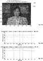
- FIG. 12A is an exemplary of an image (i.e., frame) being processed in accordance with systems and/or methods described herein as part of the experiment described herein.
- the image corresponds to the 10 th frame of a CIF sequence name akiyo.cif.
- the CIF frame has a size 352x288 pixels.
- the graphs of FIGs. 12B-I include experimental results based on the processing ofFIG. 12A.
- FIG. 12B is a graph depicting improvement in terms of bit rate for the entire frame of FIG. 12A when masks are selected to split the block into two complementary portions for encoding, over the encoding image of FIG. 12A using standard NxN transformation blocks, at the same objective quality level (represented by PSNR).
- the graph depicts the percent of bit rate improvement as a function of PSNR. It is noted that an improvement in bit-rate of over 10% was achieved for the image of FIG. 12A using the systems and/or methods described herein.
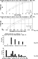
- FIG. 12C is a graph depicting improvement in terms of per non-zero (PerNZ) coefficients for the entire frame of FIG. 12A when masks are selected to split the block into two complementary portions for encoding, over the encoding image of FIG. 12A using standard NxN transformation blocks, at the same objective quality level (represented by PSNR).
- the number of transform coefficients that are non-zero after quantization are used to estimate the number of encoded bits for coding the transform coefficients. It is noted that the non-zero coefficient measure does not include the overhead of signaling bits (e.g., prediction mode, mask selection mode, and MB type).
- the graph demonstrates improvement in terms of percentage of non-zero transform coefficients of about 15% using the systems and/or methods described herein.
- FIG. 12D is a graph depicting Y-PSNR as a function of bit rate, for the C2 processing scheme and for the NxN processing scheme.
- the C2 processing scheme is the methods and/or systems described herein based on either mask selection and generation of the two complementary portions for the transformation block, or encoding the NxN block using standard methods.
- the selection of the mask based encoding or the NxN block based encoding is based on a certain measure which is associated with each mask based partition and each NxN block.
- the NxN processing scheme is based on the standard method of encoding each block as a single NxN block.
- the graph demonstrates that the C2 method achieved a lower bit rate than the NxN method, for the same PSNR value, which represents improved quality for the same bit rate.
- FIG. 12E is a graph depicting Y-PSNR as a function of the percent of non-zero transform coefficients for the entire frame, based on the C2 method and the NxN method.
- the graph depicts improved compression performance based on the C2 method (i.e., the systems and/or methods described herein), in terms of lower percentage of non-zero transform coefficients for the same PSNR, which represents improved quality for the same percentage of non-zero transform coefficients.
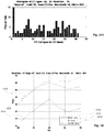
- FIG. 12F is a histogram depicting frequency of application of the intra-prediction mode for the NxN standard case.
- 1 denotes no prediction
- 2 denotes vertical prediction
- 3 denotes horizontal prediction
- 4 denotes DC prediction
- 5 denotes plane prediction.
- FIG. 12G is a histogram depicting frequency of application of the intra-prediction mode for the C2 scheme of the methods and/or systems described herein, for 16 separate predictor modes: 1 denotes no prediction, 2 denotes VV prediction, 3 denotes VH prediction, 4 denotes VD prediction, 5 denotes VP prediction, 6 denotes HV prediction, ...., 17 denotes PP prediction.
- FIG. 12H is a histogram depicting frequency of application of each mask of the library of 30 rotational symmetry masks.
- FIG. 12I is a graph depicting the ratio of three variables as a function of Qp.
Claims (20)
- Vorrichtung, die zum Generieren eines Satzes von Transformationskoeffizienten zum Codieren eines Blocks in einem Frame oder Abschnitt davon vorgesehen ist, umfassend:
einen Mediencodierer, der an eine Datenschnittstelle gekoppelt ist, die vorgesehen ist, um einen Frame oder Abschnitt davon zu empfangen, wobei der Mediencodierer vorgesehen ist zum:Auswählen einer Rotationssymmetriemaske für den Block aus einer Vielzahl von Rotationssymmetriemasken, die eine Vielzahl von unterschiedlichen Rotationssymmetrien in einem mehrdimensionalen Raum mit einer Größe und einer Form wie der Block definieren;Teilen des Blocks in zwei komplementäre Abschnitte basierend auf der Rotationssymmetriemaske;Generieren eines Paares von Rotationssymmetrieblöcken, die jeweils einen der beiden komplementären Abschnitte aufweisen; undBerechnen mindestens eines Transformationskoeffizienten für mindestens ein Element des Paares von Rotationssymmetrieblöcken;wobei der Mediencodierer vorgesehen ist, um jedes jeweilige Element des Paares von Rotationssymmetrieblöcken basierend auf dem jeweiligen einen der beiden komplementären Abschnitte zu generieren, und ein zweidimensionaler, 2D, Spiegel des jeweiligen Abschnitts zugefügt wird, um einen Block mit einer Größe und Form des Blocks zu bilden. - Vorrichtung nach einem der vorhergehenden Ansprüche, wobei die Vielzahl der Rotationssymmetriemasken sich in einer Bibliothek für Rotationssymmetriemasken befindet; wobei der Mediencodierer vorgesehen ist, um basierend auf mindestens einer von einer Größe und einer Form des Blocks die Bibliothek für Rotationssymmetriemasken aus einer Vielzahl von Bibliotheken für Rotationssymmetriemasken auszuwählen.
- Vorrichtung nach Anspruch 2, wobei der Mediencodierer vorgesehen ist, um die Bibliothek für Rotationssymmetriemasken basierend auf Kompressionspräferenz für den Block aus einer Vielzahl von Bibliotheken von Rotationssymmetriemasken auszuwählen.
- Vorrichtung nach einem der Ansprüche 2 bis 3, wobei der Mediencodierer vorgesehen ist, um die Bibliothek für Rotationssymmetriemasken basierend auf einer Klassifizierung der Videodaten, die den Frame oder Abschnitt davon umfassen, aus einer Vielzahl von Bibliotheken von Rotationssymmetriemasken auszuwählen.
- Vorrichtung nach einem der Ansprüche 2 bis 4, wobei der mehrdimensionale Raum ein zweidimensionaler Raum ist, wobei die Vielzahl der unterschiedlichen Rotationssymmetriemasken eine Vielzahl von Matrizes umfasst, die jeweils eine unterschiedliche Linie definieren, die gegenüber liegende Ränder des zweidimensionalen Raums verbindet, um den zweidimensionalen Raum in zwei komplementäre Abschnitte zu teilen.
- Vorrichtung nach einem der vorhergehenden Ansprüche, wobei der Mediencodierer vorgesehen ist, um den mindestens einen Transformationskoeffizienten unter Verwendung von mindestens einem räumlichen Prädikator zu codieren, der mit mindestens einem der beiden komplementären Abschnitte des Blocks verknüpft ist.
- Vorrichtung nach einem der vorhergehenden Ansprüche, wobei der Mediencodierer vorgesehen ist, um den mindestens einen Transformationskoeffizienten unter Verwendung von mindestens einem zeitlichen Prädikator zu codieren, der mit mindestens einem der beiden komplementären Abschnitte des Blocks verknüpft ist.
- Vorrichtung nach einem der vorhergehenden Ansprüche, wobei der Mediencodierer vorgesehen ist, um mindestens einen der Transformationskoeffizienten von jedem des Paares der Rotationssymmetrieblöcke unter Verwendung eines räumlichen Prädikators zu codieren, der mit dem jeweiligen einen der beiden komplementären Abschnitte in Beziehung steht.
- Vorrichtung nach einem der vorhergehenden Ansprüche, wobei der Mediencodierer vorgesehen ist, um mindestens einen der Transformationskoeffizienten von jedem des Paares der Rotationssymmetrieblöcke unter Verwendung eines Bewegungsvektors zu codieren, der mit dem jeweiligen einen der beiden komplementären Abschnitte verknüpft ist.
- Vorrichtung nach einem der vorhergehenden Ansprüche, wobei der Mediencodierer vorgesehen ist, um die Rotationssymmetriemaske basierend auf einem Ergebnis eines Transformationsprozesses oder einer Schätzung eines Ergebnisses eines Transformationsprozesses auszuwählen, der auf mindestens einen der beiden rotationssymmetrischen Blöcke angewendet wird.
- Vorrichtung nach einem der vorhergehenden Ansprüche, wobei der Mediencodierer vorgesehen ist, um die Rotationssymmetriemaske basierend auf einem Ergebnis oder einer Schätzung eines Ergebnisses von mindestens einem von einem Quantifizierungsprozess und einem Codierprozess auszuwählen, der auf den mindestens einen Transformationskoeffizienten für mindestens ein Element des Paares der Rotationssymmetrieblöcke angewendet wird.
- Vorrichtung nach einem der vorhergehenden Ansprüche, wobei der Mediencodierer vorgesehen ist, um die Rotationssymmetriemaske gemäß einem Muster der Pixelwerte in dem Block auszuwählen.
- Vorrichtung nach einem der vorhergehenden Ansprüche, wobei der Mediencodierer vorgesehen ist, um die Rotationssymmetriemaske basierend auf Inhalt auszuwählen, der aus mindestens einem der räumlich benachbarten Blöcke des Blocks und der zeitlich benachbarten Blöcke des Blocks extrahiert wurde, wobei der extrahierte Inhalt entsprechend einem Muster von Pixelwerten in den räumlich oder zeitlich benachbarten Blöcken ist.
- Vorrichtung nach einem der vorhergehenden Ansprüche, wobei der Mediencodierer vorgesehen ist, um eine Rotationssymmetriemaske basierend auf Informationen auszuwählen, die mit mindestens einem der räumlich benachbarten Blöcke des Blocks und der zeitlich benachbarten Blöcke des Blocks assoziiert ist; wobei die Informationen, die mit mindestens einer von der Gruppe bestehend aus räumlich und zeitlich benachbarten Blöcken assoziiert sind, mit Prädiktion in Beziehung stehen.
- Vorrichtung nach einem der vorhergehenden Ansprüche, wobei der Mediencodierer vorgesehen ist, um eine Rotationssymmetriemaske basierend auf Kompressionspräferenz für den Block auszuwählen.
- Vorrichtung nach einem der vorhergehenden Ansprüche, wobei die ausgewählte Rotationssymmetriemaske vorgesehen ist, um eine Linie zu definieren, die gegenüber liegende Ränder eines Rechtecks verbindet, um einen rechteckigen Block in zwei 2D-gespiegelte komplementäre Abschnitte zu teilen.
- Verfahren zum Generieren eines Satzes von Transformationskoeffizienten eines Blocks in einem Frame oder Abschnitt davon, umfassend:Auswählen einer Rotationssymmetriemaske aus einer Bibliothek für Rotationssymmetriemasken, die eine Vielzahl von unterschiedlichen Rotationssymmetriemasken umfasst, die eine Vielzahl von unterschiedlichen Rotationssymmetrien in einem mehrdimensionalen Raum mit einer Größe und einer Form wie der Block definieren;Teilen des Blocks in zwei komplementäre Abschnitte basierend auf der Rotationssymmetriemaske;Generieren eines Paares von Rotationssymmetrieblöcken, von denen jeder einen jeweiligen einen der beiden komplementären Abschnitte aufweist; wobei jedes jeweilige Element des Paares von Rotationssymmetrieblöcken basierend auf dem jeweiligen einen der beiden komplementären Abschnitte generiert wird und ein zweidimensionaler, 2D, Spiegel des jeweiligen Abschnitts zugefügt wird, um einen Block mit einer Größe und Form des Blocks zu bilden.Berechnen mindestens eines Transformationskoeffizienten für jedes Element des Paares von Rotationssymmetrieblöcken.
- Vorrichtung, die zum Decodieren eines Blocks von einem Frame oder Abschnitt davon vorgesehen ist, umfassend:
einen Mediendecoder, der an eine Datenschnittstelle gekoppelt ist, die vorgesehen ist, um mindestens einen Transformationskoeffizienten, der mindestens ein Element eines Paares von Rotationssymmetrieblöcken repräsentiert, und ein Signal zu empfangen, welches eine assoziierte ausgewählte Rotationssymmetriemaske repräsentiert, wobei die Rotationssymmetriemaske eine Rotationssymmetrie in einem mehrdimensionalen Raum mit einer Größe und einer Form als Block von einem Frame oder Abschnitt davon definiert, wobei der Mediendecoder für Folgendes vorgesehen ist:Berechnen des Paares von Rotationssymmetrieblöcken basierend auf inverser Transformation des empfangenen mindestens einen Transformationskoeffizienten, wobei jedes jeweilige Element des Paares von Rotationssymmetrieblöcken einen jeweiligen der beiden komplementären Abschnitte aufweist; wobei jedes jeweilige Element des Paares von Rotationssymmetrieblöcken basierend auf dem jeweiligen einen der beiden komplementären Abschnitte und einem zweidimensionalen, 2D, Spiegel des jeweiligen Abschnitts generiert wird, der zugefügt wird, um einen Block mit einer Größe und Form des Blocks zu bilden; undRekonstruieren eines Blocks aus den beiden komplementären Abschnitten basierend auf der Rotationssymmetriemaske. - Verfahren zum Rekonstruieren eines Blocks aus einem Frame oder Abschnitt davon, umfassend:Empfangen von mindestens einem Transformationskoeffizienten, der mindestens ein Element eines Paares von Rotationssymmetrieblöcken repräsentiert, und eines Signals, welches eine assoziierte ausgewählte Rotationssymmetriemaske repräsentiert, wobei die Rotationssymmetriemaske eine Rotationssymmetrie in einem mehrdimensionalen Raum mit einer Größe und einer Form als Block von einem Frame oder Abschnitt davon definiert;Berechnen des Paares von Rotationssymmetrieblöcken basierend auf inverser Transformation des empfangenen mindestens einen Transformationskoeffizienten, wobei jedes jeweilige Element des Paares von Rotationssymmetrieblöcken einen jeweiligen der beiden komplementären Abschnitte aufweist; wobei jedes jeweilige Element des Paares von Rotationssymmetrieblöcken basierend auf dem jeweiligen einen der beiden komplementären Abschnitte und einem zweidimensionalen, 2D, Spiegel des jeweiligen Abschnitts generiert wird, der zugefügt wird, um einen Block mit einer Größe und Form des Blocks zu bilden; undRekonstruieren eines Blocks aus den beiden komplementären Abschnitten basierend auf der Rotationssymmetriemaske.
- Computerprogramm, das ausgestaltet ist, um bei Ausführung auf einem Computer ein Verfahren gemäß Anspruch 17 oder 19 durchzuführen.
Applications Claiming Priority (1)
| Application Number | Priority Date | Filing Date | Title |
|---|---|---|---|
| PCT/EP2014/074639 WO2016074745A1 (en) | 2014-11-14 | 2014-11-14 | Systems and methods for processing a block of a digital image |
Publications (2)
| Publication Number | Publication Date |
|---|---|
| EP3207699A1 EP3207699A1 (de) | 2017-08-23 |
| EP3207699B1 true EP3207699B1 (de) | 2021-06-09 |
Family
ID=51900444
Family Applications (1)
| Application Number | Title | Priority Date | Filing Date |
|---|---|---|---|
| EP14798877.8A Active EP3207699B1 (de) | 2014-11-14 | 2014-11-14 | Systeme und verfahren zur verarbeitung eines blocks eines digitalbildes |
Country Status (7)
| Country | Link |
|---|---|
| US (2) | US10742976B2 (de) |
| EP (1) | EP3207699B1 (de) |
| JP (1) | JP6496821B2 (de) |
| KR (2) | KR102138650B1 (de) |
| CN (1) | CN107005702B (de) |
| BR (1) | BR112017010007B1 (de) |
| WO (1) | WO2016074745A1 (de) |
Families Citing this family (6)
| Publication number | Priority date | Publication date | Assignee | Title |
|---|---|---|---|---|
| WO2016074745A1 (en) | 2014-11-14 | 2016-05-19 | Huawei Technologies Co., Ltd. | Systems and methods for processing a block of a digital image |
| JP6443869B2 (ja) * | 2014-11-14 | 2018-12-26 | ホアウェイ・テクノロジーズ・カンパニー・リミテッド | デジタル画像を処理するためのシステムおよび方法 |
| WO2016074746A1 (en) * | 2014-11-14 | 2016-05-19 | Huawei Technologies Co., Ltd. | Systems and methods for mask based processing of a block of a digital image |
| CN110268714B (zh) | 2017-02-02 | 2021-12-21 | 华为技术有限公司 | 图像处理装置、视频编解码装置及相关方法和存储介质 |
| CN110876084B (zh) * | 2018-08-29 | 2021-01-01 | 浙江大学 | 处理和传输媒体数据的方法和装置 |
| CN113344092B (zh) * | 2021-06-18 | 2022-10-11 | 中科迈航信息技术有限公司 | Ai的图像识别方法及终端装置 |
Family Cites Families (40)
| Publication number | Priority date | Publication date | Assignee | Title |
|---|---|---|---|---|
| DE69225365T2 (de) * | 1991-08-30 | 1998-11-19 | Fuji Xerox Co Ltd | Bildsignalkodierungsvorrichtung |
| JPH0783478B2 (ja) * | 1992-01-30 | 1995-09-06 | 松下電器産業株式会社 | 画像符号化装置 |
| JP3196906B2 (ja) * | 1992-08-21 | 2001-08-06 | 富士ゼロックス株式会社 | 画像信号の符号化装置 |
| JPH0787493A (ja) | 1993-09-14 | 1995-03-31 | Oki Electric Ind Co Ltd | フレーム内挿方法 |
| EP1274253A3 (de) * | 1995-08-29 | 2005-10-12 | Sharp Kabushiki Kaisha | Videokodierungsvorrichtung und Videodekodierungsvorrichtung mit bewegungskompensierter Interframe-Prädiktion |
| DE69732865T2 (de) | 1996-01-29 | 2006-04-13 | Matsushita Electric Industrial Co., Ltd., Kadoma | Kodierer mit Mitteln zur Ergänzung eines digitalen Bildes mit Bildelementen |
| EP1788815A3 (de) | 1997-11-05 | 2008-10-15 | Sony Corporation | Datenratesteuerung zur Videotranskodierung mit Bildauflösungsumwandlung |
| JP2008109700A (ja) | 1997-11-05 | 2008-05-08 | Sony Corp | ディジタル信号変換方法およびディジタル信号変換装置 |
| US8050329B2 (en) * | 1998-06-26 | 2011-11-01 | Mediatek Inc. | Method and apparatus for generic scalable shape coding |
| JP2002325170A (ja) * | 2001-04-24 | 2002-11-08 | Canon Inc | 画像処理装置及びその方法並びにプログラムコード、記憶媒体 |
| JP4147789B2 (ja) | 2002-03-07 | 2008-09-10 | ソニー株式会社 | 画像処理装置および画像処理方法、並びにプログラムおよび記録媒体 |
| JP4025570B2 (ja) * | 2002-04-03 | 2007-12-19 | 日本電信電話株式会社 | 動画像符号化方法、動画像復号方法、動画像符号化装置、動画像復号装置、動画像符号化プログラム、動画像復号プログラム、動画像符号化プログラムを記録した記録媒体、動画像復号プログラムを記録した記録媒体 |
| JP2004297416A (ja) | 2003-03-26 | 2004-10-21 | Monolith Co Ltd | 対応点情報圧縮方法および装置 |
| JP2006094053A (ja) * | 2004-09-22 | 2006-04-06 | Fuji Photo Film Co Ltd | フォトムービー作成方法および装置、並びにフォトムービー作成プログラム |
| US7756348B2 (en) | 2006-10-30 | 2010-07-13 | Hewlett-Packard Development Company, L.P. | Method for decomposing a video sequence frame |
| CN101771868B (zh) * | 2008-12-31 | 2016-03-02 | 华为技术有限公司 | 对图像的量化处理方法及装置 |
| JP2012089905A (ja) | 2009-01-13 | 2012-05-10 | Hitachi Ltd | 画像符号化装置および画像符号化方法、画像復号化装置および画像復号化方法 |
| KR20110045949A (ko) * | 2009-10-28 | 2011-05-04 | 삼성전자주식회사 | 회전 변환을 이용한 영상 부호화, 복호화 방법 및 장치 |
| CN105959688B (zh) * | 2009-12-01 | 2019-01-29 | 数码士有限公司 | 用于解码高分辨率图像的方法 |
| JP5456907B2 (ja) * | 2009-12-04 | 2014-04-02 | トムソン ライセンシング | テクスチャー・パターン適応式の分割ブロック変換 |
| WO2011088593A1 (en) * | 2010-01-25 | 2011-07-28 | Thomson Licensing | Method and device for encoding of an image block and method and device for decoding of an image block |
| US8879632B2 (en) | 2010-02-18 | 2014-11-04 | Qualcomm Incorporated | Fixed point implementation for geometric motion partitioning |
| CN102215396A (zh) | 2010-04-09 | 2011-10-12 | 华为技术有限公司 | 一种视频编解码方法和系统 |
| EP2559248A2 (de) | 2010-04-12 | 2013-02-20 | Qualcomm Incorporated | Fixpunktimplementierung für geometrische bewegungsteilung |
| US9020043B2 (en) * | 2010-05-10 | 2015-04-28 | Google Inc. | Pathway indexing in flexible partitioning |
| JP5590390B2 (ja) | 2010-07-15 | 2014-09-17 | ソニー株式会社 | 画像処理装置および方法 |
| CN102957907B (zh) * | 2011-08-31 | 2016-06-29 | 华为技术有限公司 | 一种变换块位置信息的获取方法和模块 |
| EP3657788B1 (de) | 2011-11-11 | 2021-08-04 | GE Video Compression, LLC | Wirksame vorhersage unter verwendung einer partitionskodierung |
| US9179162B2 (en) * | 2011-12-02 | 2015-11-03 | Futurewei Technologies, Inc. | Image transform zero coefficient selection and zero-skip transmission for arbitrary shape transform coding |
| CN104350753B (zh) | 2012-06-01 | 2019-07-09 | 威勒斯媒体国际有限公司 | 算术解码装置、图像解码装置、算术编码装置以及图像编码装置 |
| US9883198B2 (en) * | 2012-11-13 | 2018-01-30 | Intel Corporation | Video codec architecture for next generation video |
| US20140307780A1 (en) | 2013-04-11 | 2014-10-16 | Mitsubishi Electric Research Laboratories, Inc. | Method for Video Coding Using Blocks Partitioned According to Edge Orientations |
| JP6250805B2 (ja) * | 2013-07-19 | 2017-12-20 | ホアウェイ・テクノロジーズ・カンパニー・リミテッド | 深度ベース・ブロック・パーティショニングを使用して、テクスチャブロックを符号化および復号するための方法ならびに装置 |
| WO2015142070A1 (ko) * | 2014-03-19 | 2015-09-24 | 삼성전자 주식회사 | 경계 필터링을 수반한 비디오 부호화 및 비디오 복호화 방법 및 장치 |
| US20180176559A1 (en) * | 2014-03-19 | 2018-06-21 | Samsung Electronics Co., Ltd. | Method for performing filtering at partition boundary of block related to 3d image |
| US9584814B2 (en) * | 2014-05-15 | 2017-02-28 | Intel Corporation | Content adaptive background foreground segmentation for video coding |
| WO2016074746A1 (en) * | 2014-11-14 | 2016-05-19 | Huawei Technologies Co., Ltd. | Systems and methods for mask based processing of a block of a digital image |
| JP6443869B2 (ja) * | 2014-11-14 | 2018-12-26 | ホアウェイ・テクノロジーズ・カンパニー・リミテッド | デジタル画像を処理するためのシステムおよび方法 |
| WO2016074745A1 (en) * | 2014-11-14 | 2016-05-19 | Huawei Technologies Co., Ltd. | Systems and methods for processing a block of a digital image |
| KR101618795B1 (ko) | 2014-11-28 | 2016-05-12 | 주식회사 폴라리언트 | 이동체의 3차원 자세 및 위치 인식 장치 |
-
2014
- 2014-11-14 WO PCT/EP2014/074639 patent/WO2016074745A1/en active Application Filing
- 2014-11-14 EP EP14798877.8A patent/EP3207699B1/de active Active
- 2014-11-14 KR KR1020197023960A patent/KR102138650B1/ko active IP Right Grant
- 2014-11-14 KR KR1020177015872A patent/KR102012906B1/ko active IP Right Grant
- 2014-11-14 CN CN201480083420.9A patent/CN107005702B/zh active Active
- 2014-11-14 JP JP2017525965A patent/JP6496821B2/ja active Active
- 2014-11-14 BR BR112017010007-0A patent/BR112017010007B1/pt active IP Right Grant
-
2017
- 2017-05-12 US US15/594,234 patent/US10742976B2/en active Active
-
2020
- 2020-01-23 US US16/750,880 patent/US11153564B2/en active Active
Non-Patent Citations (1)
| Title |
|---|
| None * |
Also Published As
| Publication number | Publication date |
|---|---|
| KR20190098276A (ko) | 2019-08-21 |
| JP2018501696A (ja) | 2018-01-18 |
| JP6496821B2 (ja) | 2019-04-10 |
| US20170251210A1 (en) | 2017-08-31 |
| KR102012906B1 (ko) | 2019-08-21 |
| EP3207699A1 (de) | 2017-08-23 |
| US11153564B2 (en) | 2021-10-19 |
| KR102138650B1 (ko) | 2020-07-28 |
| CN107005702B (zh) | 2020-10-16 |
| WO2016074745A1 (en) | 2016-05-19 |
| US10742976B2 (en) | 2020-08-11 |
| KR20170084213A (ko) | 2017-07-19 |
| US20200162732A1 (en) | 2020-05-21 |
| BR112017010007B1 (pt) | 2023-04-11 |
| CN107005702A (zh) | 2017-08-01 |
| BR112017010007A2 (pt) | 2018-01-02 |
Similar Documents
| Publication | Publication Date | Title |
|---|---|---|
| EP3207704B1 (de) | System und verfahren zur verarbeitung eines digitalen bildes | |
| EP3207700B1 (de) | Systeme und verfahren zur maskenbasierten verarbeitung eines blocks eines digitalen bildes | |
| US11153564B2 (en) | Systems and methods for processing a block of a digital image | |
| US9462271B2 (en) | Moving image encoding device, moving image decoding device, moving image coding method, and moving image decoding method | |
| EP3061233B1 (de) | Darstellung von blöcken mit hash-werten in einer bild- und videocodierung und -decodierung | |
| US20200288133A1 (en) | Video coding method and apparatus | |
| EP2590411A2 (de) | Vorrichtung und verfahren zur verschlüsselung und entschlüsselung von bildern für intraprädiktions-verschlüsselung | |
| EP3590193B1 (de) | Verfahren und vorrichtungen zur codierung und decodierung von digitalen bildern oder videodatenströmen | |
| US20130279582A1 (en) | Moving image encoding device, moving image decoding device, moving image encoding method and moving image decoding method | |
| JP2019134457A (ja) | デジタル画像のブロックを処理するためのシステムおよび方法 | |
| US11695958B2 (en) | Method and apparatus for encoding/decoding video signal by using edge-adaptive graph-based transform | |
| BR112017010163B1 (pt) | Aparelho para a geração de um conjunto de coeficientes de transformada de um bloco em um quadro ou uma porção do mesmo, método para a geração de um conjunto de coeficientes de um bloco em um quadro ou uma porção do mesmo e meio de armazenamento legível por computador |
Legal Events
| Date | Code | Title | Description |
|---|---|---|---|
| STAA | Information on the status of an ep patent application or granted ep patent |
Free format text: STATUS: THE INTERNATIONAL PUBLICATION HAS BEEN MADE |
|
| PUAI | Public reference made under article 153(3) epc to a published international application that has entered the european phase |
Free format text: ORIGINAL CODE: 0009012 |
|
| STAA | Information on the status of an ep patent application or granted ep patent |
Free format text: STATUS: REQUEST FOR EXAMINATION WAS MADE |
|
| 17P | Request for examination filed |
Effective date: 20170517 |
|
| AK | Designated contracting states |
Kind code of ref document: A1 Designated state(s): AL AT BE BG CH CY CZ DE DK EE ES FI FR GB GR HR HU IE IS IT LI LT LU LV MC MK MT NL NO PL PT RO RS SE SI SK SM TR |
|
| AX | Request for extension of the european patent |
Extension state: BA ME |
|
| DAX | Request for extension of the european patent (deleted) | ||
| STAA | Information on the status of an ep patent application or granted ep patent |
Free format text: STATUS: EXAMINATION IS IN PROGRESS |
|
| 17Q | First examination report despatched |
Effective date: 20190124 |
|
| GRAP | Despatch of communication of intention to grant a patent |
Free format text: ORIGINAL CODE: EPIDOSNIGR1 |
|
| STAA | Information on the status of an ep patent application or granted ep patent |
Free format text: STATUS: GRANT OF PATENT IS INTENDED |
|
| INTG | Intention to grant announced |
Effective date: 20210128 |
|
| GRAS | Grant fee paid |
Free format text: ORIGINAL CODE: EPIDOSNIGR3 |
|
| GRAA | (expected) grant |
Free format text: ORIGINAL CODE: 0009210 |
|
| STAA | Information on the status of an ep patent application or granted ep patent |
Free format text: STATUS: THE PATENT HAS BEEN GRANTED |
|
| AK | Designated contracting states |
Kind code of ref document: B1 Designated state(s): AL AT BE BG CH CY CZ DE DK EE ES FI FR GB GR HR HU IE IS IT LI LT LU LV MC MK MT NL NO PL PT RO RS SE SI SK SM TR |
|
| REG | Reference to a national code |
Ref country code: GB Ref legal event code: FG4D |
|
| REG | Reference to a national code |
Ref country code: CH Ref legal event code: EP Ref country code: AT Ref legal event code: REF Ref document number: 1401439 Country of ref document: AT Kind code of ref document: T Effective date: 20210615 |
|
| REG | Reference to a national code |
Ref country code: DE Ref legal event code: R096 Ref document number: 602014078041 Country of ref document: DE |
|
| REG | Reference to a national code |
Ref country code: IE Ref legal event code: FG4D |
|
| REG | Reference to a national code |
Ref country code: LT Ref legal event code: MG9D |
|
| PG25 | Lapsed in a contracting state [announced via postgrant information from national office to epo] |
Ref country code: LT Free format text: LAPSE BECAUSE OF FAILURE TO SUBMIT A TRANSLATION OF THE DESCRIPTION OR TO PAY THE FEE WITHIN THE PRESCRIBED TIME-LIMIT Effective date: 20210609 Ref country code: FI Free format text: LAPSE BECAUSE OF FAILURE TO SUBMIT A TRANSLATION OF THE DESCRIPTION OR TO PAY THE FEE WITHIN THE PRESCRIBED TIME-LIMIT Effective date: 20210609 Ref country code: BG Free format text: LAPSE BECAUSE OF FAILURE TO SUBMIT A TRANSLATION OF THE DESCRIPTION OR TO PAY THE FEE WITHIN THE PRESCRIBED TIME-LIMIT Effective date: 20210909 Ref country code: HR Free format text: LAPSE BECAUSE OF FAILURE TO SUBMIT A TRANSLATION OF THE DESCRIPTION OR TO PAY THE FEE WITHIN THE PRESCRIBED TIME-LIMIT Effective date: 20210609 |
|
| REG | Reference to a national code |
Ref country code: AT Ref legal event code: MK05 Ref document number: 1401439 Country of ref document: AT Kind code of ref document: T Effective date: 20210609 |
|
| REG | Reference to a national code |
Ref country code: NL Ref legal event code: MP Effective date: 20210609 |
|
| PG25 | Lapsed in a contracting state [announced via postgrant information from national office to epo] |
Ref country code: NO Free format text: LAPSE BECAUSE OF FAILURE TO SUBMIT A TRANSLATION OF THE DESCRIPTION OR TO PAY THE FEE WITHIN THE PRESCRIBED TIME-LIMIT Effective date: 20210909 Ref country code: RS Free format text: LAPSE BECAUSE OF FAILURE TO SUBMIT A TRANSLATION OF THE DESCRIPTION OR TO PAY THE FEE WITHIN THE PRESCRIBED TIME-LIMIT Effective date: 20210609 Ref country code: SE Free format text: LAPSE BECAUSE OF FAILURE TO SUBMIT A TRANSLATION OF THE DESCRIPTION OR TO PAY THE FEE WITHIN THE PRESCRIBED TIME-LIMIT Effective date: 20210609 Ref country code: LV Free format text: LAPSE BECAUSE OF FAILURE TO SUBMIT A TRANSLATION OF THE DESCRIPTION OR TO PAY THE FEE WITHIN THE PRESCRIBED TIME-LIMIT Effective date: 20210609 Ref country code: GR Free format text: LAPSE BECAUSE OF FAILURE TO SUBMIT A TRANSLATION OF THE DESCRIPTION OR TO PAY THE FEE WITHIN THE PRESCRIBED TIME-LIMIT Effective date: 20210910 |
|
| PG25 | Lapsed in a contracting state [announced via postgrant information from national office to epo] |
Ref country code: SM Free format text: LAPSE BECAUSE OF FAILURE TO SUBMIT A TRANSLATION OF THE DESCRIPTION OR TO PAY THE FEE WITHIN THE PRESCRIBED TIME-LIMIT Effective date: 20210609 Ref country code: SK Free format text: LAPSE BECAUSE OF FAILURE TO SUBMIT A TRANSLATION OF THE DESCRIPTION OR TO PAY THE FEE WITHIN THE PRESCRIBED TIME-LIMIT Effective date: 20210609 Ref country code: EE Free format text: LAPSE BECAUSE OF FAILURE TO SUBMIT A TRANSLATION OF THE DESCRIPTION OR TO PAY THE FEE WITHIN THE PRESCRIBED TIME-LIMIT Effective date: 20210609 Ref country code: CZ Free format text: LAPSE BECAUSE OF FAILURE TO SUBMIT A TRANSLATION OF THE DESCRIPTION OR TO PAY THE FEE WITHIN THE PRESCRIBED TIME-LIMIT Effective date: 20210609 Ref country code: NL Free format text: LAPSE BECAUSE OF FAILURE TO SUBMIT A TRANSLATION OF THE DESCRIPTION OR TO PAY THE FEE WITHIN THE PRESCRIBED TIME-LIMIT Effective date: 20210609 Ref country code: PT Free format text: LAPSE BECAUSE OF FAILURE TO SUBMIT A TRANSLATION OF THE DESCRIPTION OR TO PAY THE FEE WITHIN THE PRESCRIBED TIME-LIMIT Effective date: 20211011 Ref country code: RO Free format text: LAPSE BECAUSE OF FAILURE TO SUBMIT A TRANSLATION OF THE DESCRIPTION OR TO PAY THE FEE WITHIN THE PRESCRIBED TIME-LIMIT Effective date: 20210609 Ref country code: ES Free format text: LAPSE BECAUSE OF FAILURE TO SUBMIT A TRANSLATION OF THE DESCRIPTION OR TO PAY THE FEE WITHIN THE PRESCRIBED TIME-LIMIT Effective date: 20210609 Ref country code: AT Free format text: LAPSE BECAUSE OF FAILURE TO SUBMIT A TRANSLATION OF THE DESCRIPTION OR TO PAY THE FEE WITHIN THE PRESCRIBED TIME-LIMIT Effective date: 20210609 |
|
| PG25 | Lapsed in a contracting state [announced via postgrant information from national office to epo] |
Ref country code: PL Free format text: LAPSE BECAUSE OF FAILURE TO SUBMIT A TRANSLATION OF THE DESCRIPTION OR TO PAY THE FEE WITHIN THE PRESCRIBED TIME-LIMIT Effective date: 20210609 |
|
| REG | Reference to a national code |
Ref country code: DE Ref legal event code: R097 Ref document number: 602014078041 Country of ref document: DE |
|
| PLBE | No opposition filed within time limit |
Free format text: ORIGINAL CODE: 0009261 |
|
| STAA | Information on the status of an ep patent application or granted ep patent |
Free format text: STATUS: NO OPPOSITION FILED WITHIN TIME LIMIT |
|
| PG25 | Lapsed in a contracting state [announced via postgrant information from national office to epo] |
Ref country code: DK Free format text: LAPSE BECAUSE OF FAILURE TO SUBMIT A TRANSLATION OF THE DESCRIPTION OR TO PAY THE FEE WITHIN THE PRESCRIBED TIME-LIMIT Effective date: 20210609 |
|
| 26N | No opposition filed |
Effective date: 20220310 |
|
| PG25 | Lapsed in a contracting state [announced via postgrant information from national office to epo] |
Ref country code: AL Free format text: LAPSE BECAUSE OF FAILURE TO SUBMIT A TRANSLATION OF THE DESCRIPTION OR TO PAY THE FEE WITHIN THE PRESCRIBED TIME-LIMIT Effective date: 20210609 |
|
| PG25 | Lapsed in a contracting state [announced via postgrant information from national office to epo] |
Ref country code: MC Free format text: LAPSE BECAUSE OF FAILURE TO SUBMIT A TRANSLATION OF THE DESCRIPTION OR TO PAY THE FEE WITHIN THE PRESCRIBED TIME-LIMIT Effective date: 20210609 |
|
| REG | Reference to a national code |
Ref country code: CH Ref legal event code: PL |
|
| PG25 | Lapsed in a contracting state [announced via postgrant information from national office to epo] |
Ref country code: LU Free format text: LAPSE BECAUSE OF NON-PAYMENT OF DUE FEES Effective date: 20211114 Ref country code: IT Free format text: LAPSE BECAUSE OF FAILURE TO SUBMIT A TRANSLATION OF THE DESCRIPTION OR TO PAY THE FEE WITHIN THE PRESCRIBED TIME-LIMIT Effective date: 20210609 Ref country code: BE Free format text: LAPSE BECAUSE OF NON-PAYMENT OF DUE FEES Effective date: 20211130 |
|
| REG | Reference to a national code |
Ref country code: BE Ref legal event code: MM Effective date: 20211130 |
|
| PG25 | Lapsed in a contracting state [announced via postgrant information from national office to epo] |
Ref country code: LI Free format text: LAPSE BECAUSE OF NON-PAYMENT OF DUE FEES Effective date: 20211130 Ref country code: CH Free format text: LAPSE BECAUSE OF NON-PAYMENT OF DUE FEES Effective date: 20211130 |
|
| REG | Reference to a national code |
Ref country code: FR Ref legal event code: PLFP Year of fee payment: 9 |
|
| PG25 | Lapsed in a contracting state [announced via postgrant information from national office to epo] |
Ref country code: IE Free format text: LAPSE BECAUSE OF NON-PAYMENT OF DUE FEES Effective date: 20211114 |
|
| PG25 | Lapsed in a contracting state [announced via postgrant information from national office to epo] |
Ref country code: HU Free format text: LAPSE BECAUSE OF FAILURE TO SUBMIT A TRANSLATION OF THE DESCRIPTION OR TO PAY THE FEE WITHIN THE PRESCRIBED TIME-LIMIT; INVALID AB INITIO Effective date: 20141114 |
|
| P01 | Opt-out of the competence of the unified patent court (upc) registered |
Effective date: 20230524 |
|
| PG25 | Lapsed in a contracting state [announced via postgrant information from national office to epo] |
Ref country code: CY Free format text: LAPSE BECAUSE OF FAILURE TO SUBMIT A TRANSLATION OF THE DESCRIPTION OR TO PAY THE FEE WITHIN THE PRESCRIBED TIME-LIMIT Effective date: 20210609 |
|
| PGFP | Annual fee paid to national office [announced via postgrant information from national office to epo] |
Ref country code: FR Payment date: 20230929 Year of fee payment: 10 |
|
| PGFP | Annual fee paid to national office [announced via postgrant information from national office to epo] |
Ref country code: GB Payment date: 20231006 Year of fee payment: 10 |
|
| PGFP | Annual fee paid to national office [announced via postgrant information from national office to epo] |
Ref country code: DE Payment date: 20230929 Year of fee payment: 10 |
|
| PG25 | Lapsed in a contracting state [announced via postgrant information from national office to epo] |
Ref country code: MK Free format text: LAPSE BECAUSE OF FAILURE TO SUBMIT A TRANSLATION OF THE DESCRIPTION OR TO PAY THE FEE WITHIN THE PRESCRIBED TIME-LIMIT Effective date: 20210609 |