EP3207643B1 - Vorrichtung, system und verfahren zur reduzierung von kommunikationsübersprechen zwischen kanälen - Google Patents
Vorrichtung, system und verfahren zur reduzierung von kommunikationsübersprechen zwischen kanälen Download PDFInfo
- Publication number
- EP3207643B1 EP3207643B1 EP15850152.8A EP15850152A EP3207643B1 EP 3207643 B1 EP3207643 B1 EP 3207643B1 EP 15850152 A EP15850152 A EP 15850152A EP 3207643 B1 EP3207643 B1 EP 3207643B1
- Authority
- EP
- European Patent Office
- Prior art keywords
- output signal
- audio output
- channel
- path
- audio
- Prior art date
- Legal status (The legal status is an assumption and is not a legal conclusion. Google has not performed a legal analysis and makes no representation as to the accuracy of the status listed.)
- Active
Links
Images


Classifications
-
- H—ELECTRICITY
- H04—ELECTRIC COMMUNICATION TECHNIQUE
- H04B—TRANSMISSION
- H04B1/00—Details of transmission systems, not covered by a single one of groups H04B3/00 - H04B13/00; Details of transmission systems not characterised by the medium used for transmission
- H04B1/38—Transceivers, i.e. devices in which transmitter and receiver form a structural unit and in which at least one part is used for functions of transmitting and receiving
- H04B1/40—Circuits
- H04B1/50—Circuits using different frequencies for the two directions of communication
- H04B1/52—Hybrid arrangements, i.e. arrangements for transition from single-path two-direction transmission to single-direction transmission on each of two paths or vice versa
- H04B1/525—Hybrid arrangements, i.e. arrangements for transition from single-path two-direction transmission to single-direction transmission on each of two paths or vice versa with means for reducing leakage of transmitter signal into the receiver
-
- H—ELECTRICITY
- H04—ELECTRIC COMMUNICATION TECHNIQUE
- H04B—TRANSMISSION
- H04B7/00—Radio transmission systems, i.e. using radiation field
- H04B7/24—Radio transmission systems, i.e. using radiation field for communication between two or more posts
- H04B7/26—Radio transmission systems, i.e. using radiation field for communication between two or more posts at least one of which is mobile
-
- H—ELECTRICITY
- H04—ELECTRIC COMMUNICATION TECHNIQUE
- H04W—WIRELESS COMMUNICATION NETWORKS
- H04W4/00—Services specially adapted for wireless communication networks; Facilities therefor
- H04W4/06—Selective distribution of broadcast services, e.g. multimedia broadcast multicast service [MBMS]; Services to user groups; One-way selective calling services
- H04W4/10—Push-to-Talk [PTT] or Push-On-Call services
Definitions
- the disclosure relates generally to the field of radio frequency communication systems, and more specifically to devices, systems, and methods for reducing communications crosstalk between channels in a radio system.
- radios may include a communication headset that allows the users to hear audio from a first radio in the left ear, and audio from a second radio in the right ear.
- the audio output signal from the second radio may interfere with the voice audio input signal on the first radio.
- This interference is referred to as crosstalk, which may result in conversation crossover where an intended recipient of the voice communication on the first radio hears both the voice of the user as well as the audio output of the second radio.
- Such communications crosstalk is highly undesirable, especially in a military setting, as it may create a security risk as well as undesirable audio interference.
- Example aspects of the present disclosed technology are described herein in the context of devices, systems, methods and computer-readable media for reducing communications crosstalk between channels in a radio system.
- Those of ordinary skill in the art will realize that the following description is illustrative only and is not intended to be in any way limiting. Other aspects will readily suggest themselves to those skilled in the art having the benefit of this disclosure.
- Fig. 1 is a diagram illustrating an example aspect of a radio system 100 for reducing communications crosstalk between channels according to one aspect of the disclosed technology.
- the system 100 may include a first radio 101 that may be in communication with a second radio 102 and a third radio 103.
- the first radio 101 may be a dual channel hand-held radio that may operate on two different frequency bands simultaneously, essentially comprising two radios in one.
- the first radio 101 may communicate with the second radio 102 on a first frequency band (e.g., VHF, covering 136-174 MHz) and may simultaneously communicate with the third radio 103 on a second frequency band (e.g., 800 MHz, covering 806-824 MHz and 851-869 MHz).
- a first frequency band e.g., VHF, covering 136-174 MHz
- the third radio 103 e.g., 800 MHz, covering 806-824 MHz and 851-869 MHz.
- the first radio 101 may be connected to a headset 101 via a first lead 131, a push-to-talk (PTT) interface module 120, and a second lead 132.
- the headset 110 may include a first speaker 111, a second speaker 112, and a microphone 113.
- the first speaker 111 may output audio communications from the second radio 102
- the second speaker may output audio communications from the third radio 103
- the microphone may be used to communicate with one or both of the second and third radios 102 and 103.
- Each of the first and second speakers 111 and 112 may, for example, have a resistance value of 230 ohms.
- the PTT interface module 120 may include a first PTT switch 121 and a second PTT switch 122 that may be toggled to activate a transmit mode during which the microphone may be used to communicate with the second radio 102 and the third radio 103, respectively.
- Each of the first and second PTT switches 121 and 122 may, for example, be a button that a user may press to activate the transmit mode on a specific channel.
- toggling the first PTT switch 121 may connect the microphone 113 to a channel used for communicating audio signals to the third radio 103; and toggling the second PTT switch 122 may connect the microphone 113 to a channel used for communicating audio signals to the second radio 102.
- the PTT interface module 120 may also include components that, when triggered by the first and second PTT switches 121 and 122, respectively attenuate audio output signals destined for the first and second speakers 111 and 112 so as to reduce or eliminate any crosstalk between the audio output signals and audio input signals captured by the microphone 113. The details of this attenuation technique are described below with reference to Fig. 2 .
- Fig. 2 is a system block diagram illustrating an example aspect of a device 200 for reducing communications crosstalk between channels according to one aspect of the disclosed technology.
- the first radio 101 may include a first transceiver 201 and a second transceiver 202.
- Each of the first and second transceivers 201 and 202 may include a receiver that receives signals using a particular radio technology and a transmitter that transmits signal using a particular radio technology.
- the first transceiver 201 may transmit and receive signals on the first frequency band (e.g., to and from the second radio 102); and the second transceiver 202 may transmit and receive signals on the second frequency band (e.g., to and from the third radio 103).
- a number of input and output channels 211, 212, 213, 214 may couple the first and second transceivers 201, 202 to the headset 110 of Fig. 1 via the PTT interface module 120.
- a first input channel 211 may couple the first transceiver 201 to the microphone 113 via the PTT interface module 120 and may be configured to carry a first audio input signal from the microphone 113 to the first transceiver 201.
- a first output channel 212 may couple the first transceiver 201 to the first speaker 111 via the PTT interface module 120 and may be configured to carry a first audio output signal from the first transceiver 201 to the first speaker 111.
- a second input channel 213 may couple the second transceiver 202 to the microphone 113 via the PTT interface module 120 and may be configured to carry a second audio input signal from the microphone 113 to the second transceiver 202.
- a second output channel 214 may couple the second transceiver 202 to the second speaker 112 via the PTT interface module 120 and may be configured to carry a second audio output signal from the second transceiver 201 to the second speaker 112.
- Each of the first and second input channels 211 and 213 constitute a small signal leg that may be configured to carry a signal having a first amplitude (e.g., 5 mV); and each of the first and second output channels 212 and 214 constitute a large signal leg that may be configured to carry a signal having a second amplitude (e.g., 5 V) that is larger than the first amplitude.
- a first amplitude e.g., 5 mV
- each of the first and second output channels 212 and 214 constitute a large signal leg that may be configured to carry a signal having a second amplitude (e.g., 5 V) that is larger than the first amplitude.
- the lead 131 of Fig. 1 may include the portion of the input and output channels 211, 212, 213, 214 that couple the headset 110 to the PTT interface module 120; and the lead 132 of Fig. 1 may include the portion of the input and output channels 211, 212, 213, 214 that couple the PTT interface module 120 to the first and second transceivers 201, 202 of the first radio 101.
- the PTT interface module 120 may include a first attenuator 231 that may be coupled to the first speaker 111 and the first transceiver 201.
- the first attenuator 231 may be configured to reduce or eliminate crosstalk between the first output channel 212 and the second input channel 213 by attenuating the first audio output signal on the first output channel 212.
- the PTT interface module may also include a second attenuator 232 that may be coupled to the second speaker 112 and the second transceiver 202.
- the second attenuator 232 may be configured to reduce crosstalk between the second output channel 214 and the first input channel 211 by attenuating the second audio output signal on the second output channel 214.
- the PTT interface module 120 may further include a first microphone switch 241 that may be coupled to the microphone 113 and the first transceiver 201, and a second microphone switch 242 that may be coupled to the microphone 113 and the second transceiver 202.
- the PTT interface module 120 may also include a first controller 221 that may be coupled to the first PTT switch 121, the first attenuator 231, and the second microphone switch 242; and a second controller that may be coupled to the second PTT switch 122, the second attenuator 232, and the first microphone switch 241.
- the user may set the radio to four different states of operation.
- the user may choose to only listen to the second radio 102 via the first speaker 111 and the third radio 103 via the second speaker 112 without activating the microphone 113. In this case, the user does not activate either the first PTT switch 121 or the second PTT switch 122 so as not to activate either the second microphone switch 242 or the first microphone switch 241.
- the first attenuator 231 may pass the first audio output signal on the first output channel 212 from the first transceiver 201 to the first speaker 111 without attenuating the first audio output signal; and the second attenuator 232 may pass the second audio output signal on the second output channel 214 from the second transceiver 202 to the second speaker 112 without attenuating the second audio output signal.
- both the first microphone switch 241 and the second microphone switch 242 are inactive and do not pass any signals on the first and second input channels 211, 213 to the first and second transceivers, 201, 202, respectively.
- the user may choose to talk via the microphone 113 to the third radio 103 while listening to the second radio 102 via the first speaker 111 and the third radio 103 via the second speaker 112.
- the user may activate only the first PTT switch 121, which in turn may trigger the first controller 221 to activate the first attenuation circuit 231 and the second microphone switch 242.
- the second microphone switch 242 When the second microphone switch 242 is activated, it may pass the second audio input signal on the second input channel 213 from the microphone 113 to the second transceiver 202.
- the first attenuator 231 When the first attenuator 231 is activated, it may attenuate the first audio output signal on the first output channel 212 thereby reducing or eliminating crosstalk between the first output channel 212 and the second input channel 213.
- the user may choose to talk via the microphone 113 to the second radio 102 while listening to the second radio 102 via the first speaker 111 and the third radio 103 via the second speaker 112.
- the user may activate only the second PTT switch 122, which in turn may trigger the second controller 222 to activate the second attenuation circuit 232 and the first microphone switch 241.
- the first microphone switch 241 When the first microphone switch 241 is activated, it may pass the first audio input signal on the first input channel 211 from the microphone 113 to the first transceiver 201.
- the second attenuator 232 When the second attenuator 232 is activated, it may attenuate the second audio output signal on the second output channel 214 thereby reducing or eliminating crosstalk between the second output channel 214 and the first input channel 211.
- the user may choose to talk via the microphone 113 to both the second radio 102 and the third radio 103 while listening to the second radio 102 via the first speaker 111 and the third radio 103 via the second speaker 112.
- the user may activate both the first PTT switch 121 and the second PTT switch 122, which in turn may trigger the second controller 222 to activate the second attenuation circuit 232 and the first microphone switch 241, and the second controller 222 to activate the second attenuation circuit 232 and the first microphone switch 241.
- the result may be a combination of the second and third states of operation such that the first and second audio input signals are transmitted from the microphone 113 to the first and second transceivers 201 and 202, respectively; and the first and second audio output signals are attenuated on the first and second output channels 212 and 214, respectively.
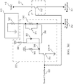
- Fig. 3A is a circuit diagram illustrating an example aspect of an attenuator 231 and a microphone switch 242 for reducing communications crosstalk between channels according to one aspect of the disclosed technology.
- the first attenuator 231 may include a first switch 301 coupled to the first controller 221, a first resistor 313 (e.g., 360 ohms) on the first output channel 212, a first attenuation component 310 coupled to the first resistor 313 and the first switch 301.
- the first switch 301 may be a push switch, a transistor, or other component that is capable of passing electric current once activated.
- the first attenuation component 310 may, for example, be an optoisolator or a similar component that is capable of controlling a signal flow across the output channel (e.g., first output channel 212).
- the first attenuation component 310 may include a first sensor 312 that is coupled in parallel with the first resistor 313, a first emitter 311 that is coupled in series with a second resistor 314 (e.g., 1 kohms) and the first switch 301, and a dielectric channel (not shown) disposed between the first emitter 311 and the first sensor 312.
- the second resistor 314 may be coupled at its other end to Vdd.
- the first emitter 311 may be a light emitting source, such as a light emitting diode (LED), or other component that may convert an electrical input signal into light.
- the first sensor 312 may be a photoresistor, a photodiode, a phototransistor, or other component that detects incoming light and either stops or impedes the flow of electric current through itself.
- the first attenuator 231 may optionally include a third resistor 315 (e.g., 10 kohms) connected at one end to Vdd and at the other end to a first node 316 connecting the first switch 301 and the first emitter 311 in order to maintain a high voltage at the first node 316.
- Vdd and ground may be power supply rails each having a specific voltage value that is suitable for proper operation of the circuit elements disclosed herein. For example, Vdd may be 5 V and ground may be 0 V.
- the second microphone switch 242 may include a second switch 302 on the second input channel 213.
- the second switch 302 may be coupled to the first controller 221 and may be configured to close (i.e., become conductive) upon activation by the first controller 221 so as to allow the second audio input signal to pass on the second input channel 213.
- the second switch 302 may be a push switch, a transistor, or other component that is capable of passing electric current once activated.
- both first and second switches 301 and 302 remain in an open (i.e., non-conductive) state, preventing the flow of electric current.
- the first switch 301 is open, the first node 316 is held at a high enough voltage level to ensure that there is insufficient voltage bias across the first emitter 311 to activate it.
- the first sensor 312 maintains a level of resistance that is sufficiently low when compared to that of the first resistor 313 in order to ensure that the first audio output signal flows through the first sensor 312 (i.e., first path) instead of through the first resistor 313 (i.e., second path). This allows the first audio output signal to remain unattenuated during the first and third states of operation.
- the first controller 221 when the first controller 221 is triggered to activate the first attenuation circuit 231 and the second microphone switch 242, the first controller 221 may activate both the first switch 301 of the first attenuator 231 and the second switch 302 of the second microphone switch 242.
- the second switch 302 When the second switch 302 is activated, it transitions from an open (i.e., non-conductive) state to a closed (i.e., conductive) state that allows electric current to pass through itself, thus allowing the second audio input signal to pass on the second input channel 213 from the microphone 113 to the second transceiver 202.
- the first switch 301 When the first switch 301 is activated, it pulls the first node 316 down to ground, thus activating the first emitter 311 by allowing electric current to flow from Vdd down through the second resistor 314 and the first emitter 311 to ground.
- the first emitter 311 When the first emitter 311 is activated, it illuminates the first sensor 312, causing the first sensor 312 to increase its level of resistance to one that is greater than that of the first resistor 313. Once the level of resistance of the first sensor 312 is sufficiently high when compared to that of the first resistor 313, the flow of the first audio output signal is redirected from the first path that takes it through the first sensor 312 to the second path that takes it through the first resistor 313.
- the first resistor 313 and resistor 381 of the first speaker 111 form a voltage divider that attenuates the first audio output signal.
- forcing the first audio output signal to flow through the first resistor 313 attenuates the first audio output signal by an amount (e.g., 3 db to 9 db) that reduces or eliminates crosstalk between the first output channel 212 and the second input channel 213.
- Fig. 3B is a circuit diagram illustrating an example aspect of an attenuator 232 and a microphone switch 241 for reducing communications crosstalk between channels according to one aspect of the disclosed technology.
- the components and the operation of the second attenuator 232 and the first microphone switch 241 are similar to those of the first attenuator 231 and the second microphone switch 242, their description is included herein for completeness.
- the second attenuator 232 may include a third switch 351 coupled to the second controller 222, a fourth resistor 363 (e.g., 360 ohms) on the second output channel 214, a second attenuation component 360 coupled to the fourth resistor 363 and the third switch 351.
- the third switch 351 may be a push switch, a transistor, or other component that is capable of passing electric current once activated.
- the second attenuation component 360 may, for example, be an optoisolator or a similar component that is capable of controlling a signal flow across the output channel (e.g., second output channel 214).
- the second attenuation component 360 may include a second sensor 362 that is coupled in parallel with the fourth resistor 363, a second emitter 361 that is coupled in series with a fifth resistor 364 (e.g., 1 kohms) and the third switch 351, and a dielectric channel (not shown) disposed between the second emitter 361 and the second sensor 362.
- the fifth resistor 364 may be coupled at its other end to Vdd.
- the second emitter 361 may be a light emitting source, such as a light emitting diode (LED), or other component that may convert an electrical input signal into light.
- LED light emitting diode
- the second sensor 362 may be a photoresistor, a photodiode, a phototransistor, or other component that detects incoming light and either stops or impedes the flow of electric current through itself.
- the second attenuator 232 may optionally include a sixth resistor 365 (e.g., 10 kohms) connected at one end to Vdd and at the other end to a second node 366 connecting the third switch 351 and the second emitter 361 in order to maintain a high voltage at the second node 366.
- the first microphone switch 241 may include a fourth switch 352 on the first input channel 211.
- the fourth switch 352 may be coupled to the second controller 222 and may be configured to close (i.e., become conductive) upon activation by the second controller 222 so as to allow the first audio input signal to pass on the first input channel 211.
- the fourth switch 352 may be a push switch, a transistor, or other component that is capable of passing electric current once activated.
- both third and fourth switches 351 and 352 remain in an open (i.e., non-conductive) state, preventing the flow of electric current.
- the third switch 351 is open, the second node 366 is held at a high enough voltage level to ensure that there is insufficient voltage bias across the second emitter 361 to activate it.
- the second sensor 362 maintains a level of resistance that is sufficiently low when compared to that of the fourth resistor 363 in order to ensure that the second audio output signal flows through the second sensor 362 (i.e., third path) instead of through the fourth resistor 363 (i.e., fourth path). This allows the second audio output signal to remain unattenuated during the first and second states of operation.
- the second controller 222 when the second controller 222 is triggered to activate the second attenuation circuit 232 and the first microphone switch 241, the second controller 222 may activate both the third switch 351 of the second attenuator 232 and the fourth switch 352 of the first microphone switch 241.
- the fourth switch 352 When the fourth switch 352 is activated, it transitions from an open (i.e., non-conductive) state to a closed (i.e., conductive) state that allows electric current to pass through itself, thus allowing the first audio input signal to pass on the first input channel 211 from the microphone 113 to the first transceiver 201.
- the third switch 351 When the third switch 351 is activated, it pulls the second node 366 down to ground, thus activating the second emitter 361 by allowing electric current to flow from Vdd down through the fifth resistor 364 and the second emitter 361 to ground.
- the second emitter 351 When the second emitter 351 is activated, it illuminates the second sensor 362, causing the second sensor 362 to increase its level of resistance to one that is greater than that of the fourth resistor 363. Once the level of resistance of the second sensor 362 is sufficiently high when compared to that of the fourth resistor 363, the flow of the second audio output signal is redirected from the third path that takes it through the second sensor 362 to the fourth path that takes it through the fourth resistor 363.
- the fourth resistor 363 and resistor 382 of the second speaker 112 form a voltage divider that attenuates the second audio output signal.
- forcing the second audio output signal to flow through the fourth resistor 363 attenuates the second audio output signal by an amount (e.g., 3 db to 9 db) that reduces or eliminates crosstalk between the second output channel 214 and the first input channel 211.
- Fig. 4 is a flow diagram illustrating an example method 400 for reducing communications crosstalk between channels according to one aspect of the disclosed technology.
- the process described in this flow diagram may be implemented in a hand-held radio system, such as the one shown in Fig. 1 .
- the process may begin in block 401, where a first audio output signal may be received.
- the first audio output signal may be received on the first output channel 212 at the PTT interface module 120, and in particular, at the first attenuator 231.
- a second audio output signal may be received.
- the second audio output signal may be received on the second output channel 214 at the PTT interface module 120, and in particular, at the second attenuator 232.
- the first attenuator 231 may be activated; and in block 407, the activated first attenuator 231 may attenuate the first audio output signal on the first output channel 212 so as to reduce or eliminate crosstalk between the first output channel 212 and the second input channel 212. The process may then proceed to block 408.
- the second attenuator 232 may be activated; and in block 412, the activated second attenuator 232 may attenuate the second audio output signal on the second output channel 214 so as to reduce or eliminate crosstalk between the second output channel 214 and the first input channel 211.
- Fig. 5 depicts one example aspect of a computer system 5 that may be used to implement the disclosed systems and methods for reducing communications crosstalk between channels according to one aspect of the disclosed technology.
- the computer system 5 may include, but not limited to, a personal computer, a notebook, tablet computer, a smart phone, a mobile device, a network server, a router, or other type of processing device.
- computer system 5 may include one or more hardware processors 15, memory 20, one or more hard disk drive(s) 30, optical drive(s) 35, serial port(s) 40, graphics card 45, audio card 50 and network card(s) 55 connected by system bus 10.
- System bus 10 may be any of several types of bus structures including a memory bus or memory controller, a peripheral bus and a local bus using any of a variety of known bus architectures.
- Processor 15 may include one or more Intel ® Core 2 Quad 2.33 GHz processors or other type of microprocessor.
- System memory 20 may include a read-only memory (ROM) 21 and random access memory (RAM) 23.
- Memory 20 may be implemented as in DRAM (dynamic RAM), EPROM, EEPROM, Flash or other type of memory architecture.
- ROM 21 stores a basic input/output system 22 (BIOS), containing the basic routines that help to transfer information between the modules of computer system 5, such as during start-up.
- BIOS basic input/output system
- RAM 23 stores operating system 24 (OS), such as Windows ® 7 Professional or other type of operating system, that is responsible for management and coordination of processes and allocation and sharing of hardware resources in computer system 5.
- OS operating system 24
- Memory 20 also stores applications and programs 25.
- Memory 20 also stores various runtime data 26 used by programs 25.
- Computer system 5 may further include hard disk drive(s) 30, such as SATA HDD, and optical disk drive(s) 35 for reading from or writing to a removable optical disk, such as a CD-ROM, DVD-ROM or other optical media.
- Drives 30 and 35 and their associated computer-readable media provide non-volatile storage of computer readable instructions, data structures, applications and program modules/subroutines that implement algorithms and methods disclosed herein.
- the exemplary computer system 5 employs magnetic and optical disks, it should be appreciated by those skilled in the art that other types of computer readable media that can store data accessible by a computer system 5, such as magnetic cassettes, flash memory cards, digital video disks, RAMs, ROMs, EPROMs and other types of memory may also be used in alternative aspects of the computer system 5.
- Computer system 5 further includes a plurality of serial ports 40, such as Universal Serial Bus (USB), for connecting data input device(s) 75, such as keyboard, mouse, touch pad and other.
- Serial ports 40 may be also be used to connect data output device(s) 80, such as printer, scanner and other, as well as other peripheral device(s) 85, such as external data storage devices and the like.
- System 5 may also include graphics card 45, such as nVidia ® GeForce ® GT 240M or other video card, for interfacing with a display 60 or other video reproduction device, such as touch-screen display.
- System 5 may also include an audio card 50 for reproducing sound via internal or external speakers 65.
- system 5 may include network card(s) 55, such as Ethernet, WiFi, GSM, Bluetooth or other wired, wireless, or cellular network interface for connecting computer system 5 to network 70, such as the Internet.
- the systems and methods described herein may be implemented in hardware, software, firmware, or any combination thereof. If implemented in software, the methods may be stored as one or more instructions or code on a non-transitory computer-readable medium.
- Computer-readable medium includes data storage.
- such computer-readable medium can comprise RAM, ROM, EEPROM, CD-ROM, Flash memory or other types of electric, magnetic, or optical storage medium, or any other medium that can be used to carry or store desired program code in the form of instructions or data structures and that can be accessed by a processor of a general purpose computer.
Landscapes
- Engineering & Computer Science (AREA)
- Computer Networks & Wireless Communication (AREA)
- Signal Processing (AREA)
- Telephone Function (AREA)
- Soundproofing, Sound Blocking, And Sound Damping (AREA)
Claims (14)
- Vorrichtung (200) zum Reduzieren von Kommunikationsübersprechen, welche Vorrichtung umfasst:einen ersten Transceiver (201) mit einem ersten Eingangskanal (211), der dazu ausgelegt ist, ein erstes Audioeingangssignal zu tragen, und einem ersten Ausgangskanal (212), der dazu ausgelegt ist, ein erstes Audioausgangssignal zu tragen;einen zweiten Transceiver (202) mit einem zweiten Eingangskanal (213), der dazu ausgelegt ist, ein zweites Audioeingangssignal zu tragen, und einem zweiten Ausgangskanal (214), der dazu ausgelegt ist, ein zweites Audioausgangssignal zu tragen;eine mit dem ersten Transceiver (201) und dem zweiten Transceiver (202) gekoppelte erste Steuerung (221), wobei die erste Steuerung dazu ausgelegt ist, das Übersprechen zwischen dem ersten Ausgangskanal und dem zweiten Eingangskanal zu reduzieren, indem sie das erste Audioausgangssignal auf ein hörbares erstes gedämpftes Audioausgangssignal auf dem ersten Ausgangskanal dämpft; undeine mit dem ersten Transceiver (201) und dem zweiten Transceiver (202) gekoppelte zweite Steuerung (222), wobei die zweite Steuerung dazu ausgelegt ist, das Übersprechen zwischen dem zweiten Ausgangskanal und dem ersten Eingangskanal zu reduzieren, indem sie das zweite Audioausgangssignal auf ein hörbares zweites gedämpftes Audioausgangssignal auf dem zweiten Ausgangskanal dämpft,wobei der erste Eingangskanal (211) und der zweite Eingangskanal (213) dazu ausgelegt sind, Signale von einem Kopfhörer (110) zu empfangen,wobei der erste Ausgangskanal (212) und der zweite Ausgangskanal (214) dazu ausgelegt sind, Signale an den Kopfhörer (212) zu übertragen, wobei eines des ersten gedämpften Audioausgangssignals und des zweiten Audioausgangssignals gleichzeitig innerhalb eines hörbaren Bereichs liegt, und das erste Audioausgangssignal und das zweite gedämpfte Audioausgangssignal gleichzeitig innerhalb eines hörbaren Bereichs liegen; undwobei die erste Steuerung (221) dazu ausgelegt ist, das erste Audioausgangssignal durch Umleiten des ersten Audioausgangssignals von einem ersten Pfad zu einem zweiten Pfad zu dämpfen, wobei ein elektrischer Widerstand des zweiten Pfads größer als der des ersten Pfads ist.
- Vorrichtung nach Anspruch 1, wobei die erste Steuerung (221) bei Auslösen dazu ausgelegt ist, Kommunikationen auf dem zweiten Eingangskanal zu ermöglichen, und das erste Audioausgangssignal zu dämpfen.
- Vorrichtung nach Anspruch 1, wobei der erste Pfad einen Optoisolator beinhaltet und der zweite Pfad einen Widerstandskörper beinhaltet.
- Vorrichtung nach Anspruch 3, wobei der Optoisolator einen parallel zu dem Widerstandskörper angeordneten Schalter beinhaltet.
- Vorrichtung nach Anspruch 4, wobei die erste Steuerung (221) bei Auslösen dazu ausgelegt ist, den Schalter in einen nichtleitenden Zustand zu öffnen, wodurch das erste Audioausgangssignal vom ersten Pfad zum zweiten Pfad umgeleitet wird.
- Vorrichtung nach Anspruch 4, wobei die erste Steuerung (221) durch eine Push-To-Talk-Taste ausgelöst wird.
- Vorrichtung nach Anspruch 1, wobei der Kopfhörer (110) ein Mikrofon (113) beinhaltet, und wobei der erste Eingangskanal und der zweite Eingangskanal zum Empfangen der Signale vom Mikrofon ausgelegt sind.
- Vorrichtung nach Anspruch 1, wobei das Übersprechen zwischen dem ersten Ausgangskanal und dem zweiten Eingangskanal um 3 db bis 9 db reduziert wird.
- Verfahren zum Reduzieren von Kommunikationsübersprechen zwischen Kanälen eines ersten Transceivers (201) und eines zweiten Transceivers (202), wobei der erste Transceiver (201) einen ersten Eingangskanal (211), der dazu ausgelegt ist, ein erstes Audioeingangssignal zu tragen, und einen ersten Ausgangskanal (212), der dazu ausgelegt ist, ein erstes Audioausgangssignal zu tragen, beinhaltet, wobei der zweite Transceiver (202) einen zweiten Eingangskanal (213), der dazu ausgelegt ist, ein zweites Audioeingangssignal zu tragen, und einen zweiten Ausgangskanal (214), der dazu ausgelegt ist, ein zweites Audioausgangssignal zu tragen, beinhaltet, welches Verfahren umfasst:Empfangen des ersten Audioausgangssignals auf dem ersten Ausgangskanal (212);Empfangen eines ersten Steuersignals zum Öffnen des zweiten Eingangskanals;Ermöglichen von Kommunikationen auf dem zweiten Eingangskanal (214) als Reaktion auf das erste Steuersignal; undDämpfen des ersten Audioausgangssignals als Reaktion auf das erste Steuersignal auf ein hörbares erstes gedämpftes Audioausgangssignal,wobei der erste Eingangskanal (211) und der zweite Eingangskanal (213) dazu ausgelegt sind, Signale von einem Kopfhörer (110) zu empfangen, undwobei der erste Ausgangskanal (212) und der zweite Ausgangskanal (214) dazu ausgelegt sind, Signale an den Kopfhörer (110) zu übertragen, undwobei das erste gedämpfte Audioausgangssignal und das zweite Audioausgangssignal gleichzeitig innerhalb eines hörbaren Bereichs liegen, undwobei das Dämpfen des ersten Audioausgangssignals das Umleiten des ersten Audioausgangssignals von einem ersten Pfad zu einem zweiten Pfad beinhaltet, wobei ein elektrischer Widerstand des zweiten Pfads größer als der des ersten Pfads ist.
- Verfahren nach Anspruch 9, ferner umfassend:Empfangen des zweiten Audioausgangssignals auf dem zweiten Ausgangskanal (214);Empfangen eines zweiten Steuersignals zum Öffnen des ersten Eingangskanals (211);Ermöglichen von Kommunikationen auf dem ersten Eingangskanal (211) als Reaktion auf das zweite Steuersignal; undDämpfen des zweiten Audioausgangssignals als Reaktion auf das zweite Steuersignal.
- Verfahren nach Anspruch 10, wobei der erste Pfad einen Optoisolator beinhaltet, und der zweite Pfad einen Widerstandskörper beinhaltet.
- Verfahren nach Anspruch 11, wobei der Optoisolator einen parallel zu dem Widerstandskörper angeordneten Schalter beinhaltet.
- Verfahren nach Anspruch 12, wobei das Dämpfen des ersten Audioausgangssignals das Öffnen des Schalters in einen nichtleitenden Zustand beinhaltet, wodurch das erste Audioausgangssignal vom ersten Pfad zum zweiten Pfad umgeleitet wird.
- Nichtflüchtiges computerlesbares Medium zur Implementierung auf einer Vorrichtung zum Reduzieren von Audioübersprechen zwischen Kanälen eines ersten Transceivers (201) und eines zweiten Transceivers (202), wobei der erste Transceiver einen ersten Eingangskanal (211), der dazu ausgelegt ist, ein erstes Audioeingangssignal zu tragen, und einen ersten Ausgangskanal (212), der dazu ausgelegt ist, ein erstes Audioausgangssignal zu tragen, beinhaltet, wobei der zweite Transceiver (202) einen zweiten Eingangskanal (213), der dazu ausgelegt ist, ein zweites Audioeingangssignal zu tragen, und einen zweiten Ausgangskanal (214), der dazu ausgelegt ist, ein zweites Audioausgangssignal zu tragen, beinhaltet, wobei das nichtflüchtige computerlesbare Medium einen ausführbaren Code umfasst, um einen Computer zu veranlassen:das erste Audioausgangssignal auf dem ersten Ausgangskanal (212) zu empfangen;ein erstes Steuersignal zum Öffnen des zweiten Eingangskanals (213) zu empfangen;Kommunikationen auf dem zweiten Eingangskanal (213) als Reaktion auf das erste Steuersignal zu ermöglichen; unddas erste Audioausgangssignal als Reaktion auf das erste Steuersignal auf ein hörbares erstes gedämpftes Audioausgangssignal zu dämpfen,wobei der erste Eingangskanal (211) und der zweite Eingangskanal (213) dazu ausgelegt sind, Signale von einem Kopfhörer (110) zu empfangen, wobei der erste Ausgangskanal (212) und der zweite Ausgangskanal (214) dazu ausgelegt sind, Signale an den Kopfhörer zu übertragen, undwobei das erste gedämpfte Audioausgangssignal und das zweite Audioausgangssignal gleichzeitig innerhalb eines hörbaren Bereichs liegen, undwobei das erste Audioausgangssignal durch Umleiten des ersten Audioausgangssignals von einem ersten Pfad zu einem zweiten Pfad gedämpft wird,wobei ein elektrischer Widerstand des zweiten Pfads größer als der des ersten Pfads ist.
Applications Claiming Priority (2)
| Application Number | Priority Date | Filing Date | Title |
|---|---|---|---|
| US201462064873P | 2014-10-16 | 2014-10-16 | |
| PCT/US2015/056043 WO2016061519A1 (en) | 2014-10-16 | 2015-10-16 | Device, system and method for reducing communications crosstalk between channels |
Publications (3)
| Publication Number | Publication Date |
|---|---|
| EP3207643A1 EP3207643A1 (de) | 2017-08-23 |
| EP3207643A4 EP3207643A4 (de) | 2018-06-20 |
| EP3207643B1 true EP3207643B1 (de) | 2022-06-15 |
Family
ID=55747439
Family Applications (1)
| Application Number | Title | Priority Date | Filing Date |
|---|---|---|---|
| EP15850152.8A Active EP3207643B1 (de) | 2014-10-16 | 2015-10-16 | Vorrichtung, system und verfahren zur reduzierung von kommunikationsübersprechen zwischen kanälen |
Country Status (3)
| Country | Link |
|---|---|
| US (2) | US10230420B2 (de) |
| EP (1) | EP3207643B1 (de) |
| WO (1) | WO2016061519A1 (de) |
Families Citing this family (1)
| Publication number | Priority date | Publication date | Assignee | Title |
|---|---|---|---|---|
| US10476548B2 (en) * | 2016-03-24 | 2019-11-12 | Black Diamond Advanced Technology, Llc | Electrically isolated push-to-talk devices |
Citations (1)
| Publication number | Priority date | Publication date | Assignee | Title |
|---|---|---|---|---|
| US20140057574A1 (en) * | 2012-08-24 | 2014-02-27 | Motorola Solutions, Inc. | Method and apparatus for controlling receive volume in a two-way radio system |
Family Cites Families (14)
| Publication number | Priority date | Publication date | Assignee | Title |
|---|---|---|---|---|
| US6160790A (en) * | 1996-12-31 | 2000-12-12 | Paradyne Corporation | Crosstalk canceller system and method |
| US6694019B1 (en) * | 1999-08-26 | 2004-02-17 | Nortel Networks Limited | Method and apparatus for infinite return loss handler for network echo canceller |
| CA2591774A1 (en) * | 2004-01-06 | 2005-07-28 | Hanler Communications Corporation | Multi-mode, multi-channel psychoacoustic processing for emergency communications |
| US7375871B2 (en) * | 2004-11-03 | 2008-05-20 | Leviton Manufacturing Co., Inc. | Electrochromic glass control device |
| FR2892608B1 (fr) | 2005-11-03 | 2008-05-30 | Techpack Int Sa | Distributeur applicateur d'un produit pateux |
| DE102005060810A1 (de) * | 2005-12-20 | 2007-07-12 | Wabco Gmbh | Taster zum Betätigen einer elektro-pneumatischen Handbremse (EPH) |
| US8073137B2 (en) * | 2006-03-06 | 2011-12-06 | Sony Ericsson Mobile Communications Ab | Audio headset |
| US9549297B2 (en) * | 2008-11-26 | 2017-01-17 | Global Market Development, Inc. | Integrated telecommunications handset |
| US9883271B2 (en) * | 2008-12-12 | 2018-01-30 | Qualcomm Incorporated | Simultaneous multi-source audio output at a wireless headset |
| US20100172522A1 (en) * | 2009-01-07 | 2010-07-08 | Pillar Ventures, Llc | Programmable earphone device with customizable controls and heartbeat monitoring |
| US8175629B2 (en) * | 2010-04-29 | 2012-05-08 | Bose Corporation | Connection-responsive push-to-talk |
| US9065414B2 (en) * | 2011-03-31 | 2015-06-23 | Intel Corporation | Automatic volume reduction |
| US9548854B2 (en) | 2012-04-13 | 2017-01-17 | Dominant Technologies, LLC | Combined in-ear speaker and microphone for radio communication |
| US9161133B2 (en) | 2013-06-24 | 2015-10-13 | Sony Corporation | Crosstalk reduction in a headset |
-
2015
- 2015-10-16 US US14/885,643 patent/US10230420B2/en active Active
- 2015-10-16 WO PCT/US2015/056043 patent/WO2016061519A1/en not_active Ceased
- 2015-10-16 EP EP15850152.8A patent/EP3207643B1/de active Active
-
2019
- 2019-02-22 US US16/283,659 patent/US10879949B2/en active Active
Patent Citations (1)
| Publication number | Priority date | Publication date | Assignee | Title |
|---|---|---|---|---|
| US20140057574A1 (en) * | 2012-08-24 | 2014-02-27 | Motorola Solutions, Inc. | Method and apparatus for controlling receive volume in a two-way radio system |
Also Published As
| Publication number | Publication date |
|---|---|
| US10879949B2 (en) | 2020-12-29 |
| EP3207643A4 (de) | 2018-06-20 |
| US20190326945A1 (en) | 2019-10-24 |
| EP3207643A1 (de) | 2017-08-23 |
| US20170012663A1 (en) | 2017-01-12 |
| US10230420B2 (en) | 2019-03-12 |
| WO2016061519A1 (en) | 2016-04-21 |
Similar Documents
| Publication | Publication Date | Title |
|---|---|---|
| US8971946B2 (en) | Privacy control in push-to-talk | |
| US20190200175A1 (en) | Electronic accessory incorporating dynamic user-controlled audio muting capabilities, related methods and communications terminal | |
| WO2021184920A1 (zh) | 一种声音的掩蔽方法、装置及终端设备 | |
| EP3437312B1 (de) | Stummschaltung von mikrofonen von physikalisch nebeneinanderstehenden vorrichtungen | |
| WO2020063046A1 (zh) | 音频播放方法、装置、电子设备及存储介质 | |
| CN108494954A (zh) | 语音通话数据检测方法、装置、存储介质及移动终端 | |
| KR102259850B1 (ko) | 동적 하울링 억제를 위한 적응적 근접 임계치들 | |
| CN115398833B (zh) | 信息监听、信息发送方法及装置、存储介质 | |
| CN108055687A (zh) | 无线网络连接方法、装置、终端设备及存储介质 | |
| CN105554234B (zh) | 一种消噪处理的方法、装置和终端 | |
| EP3523890A1 (de) | Mehrfachverstärker-repeater für ein drahtloskommunikationssystem | |
| US10028222B2 (en) | Apparatus and method for controlling power in a communication system | |
| US20200092947A1 (en) | Signal booster with coaxial cable connections | |
| US10154149B1 (en) | Audio framework extension for acoustic feedback suppression | |
| US8929960B2 (en) | Voice call processing method and apparatus for mobile terminal | |
| US10879949B2 (en) | Device, system and method for reducing communications crosstalk between channels | |
| CN110086478A (zh) | 一种射频电路及移动终端 | |
| WO2017074796A1 (en) | Transport format combination selection during self-jamming interference | |
| CN117728849A (zh) | 射频系统及其控制方法、电子设备、存储介质 | |
| US9906204B2 (en) | Tunable filter off-states for noise rejection | |
| CN108449504B (zh) | 语音通话数据检测方法、装置、存储介质及移动终端 | |
| CN108307485A (zh) | 无线网络扫描方法、装置、终端设备及存储介质 | |
| CN108429562B (zh) | 多媒体设备播放控制方法及多媒体系统 | |
| CN115278714B (zh) | 连接控制方法、装置、电子设备及存储介质 | |
| TWI878298B (zh) | 用於無線設備之間的低功率通訊鏈路的方法、裝置以及非臨時性電腦可讀取媒體 |
Legal Events
| Date | Code | Title | Description |
|---|---|---|---|
| STAA | Information on the status of an ep patent application or granted ep patent |
Free format text: STATUS: THE INTERNATIONAL PUBLICATION HAS BEEN MADE |
|
| PUAI | Public reference made under article 153(3) epc to a published international application that has entered the european phase |
Free format text: ORIGINAL CODE: 0009012 |
|
| STAA | Information on the status of an ep patent application or granted ep patent |
Free format text: STATUS: REQUEST FOR EXAMINATION WAS MADE |
|
| 17P | Request for examination filed |
Effective date: 20170511 |
|
| AK | Designated contracting states |
Kind code of ref document: A1 Designated state(s): AL AT BE BG CH CY CZ DE DK EE ES FI FR GB GR HR HU IE IS IT LI LT LU LV MC MK MT NL NO PL PT RO RS SE SI SK SM TR |
|
| AX | Request for extension of the european patent |
Extension state: BA ME |
|
| DAV | Request for validation of the european patent (deleted) | ||
| DAX | Request for extension of the european patent (deleted) | ||
| A4 | Supplementary search report drawn up and despatched |
Effective date: 20180523 |
|
| RIC1 | Information provided on ipc code assigned before grant |
Ipc: H04B 10/00 20130101AFI20180516BHEP |
|
| STAA | Information on the status of an ep patent application or granted ep patent |
Free format text: STATUS: EXAMINATION IS IN PROGRESS |
|
| 17Q | First examination report despatched |
Effective date: 20201123 |
|
| GRAP | Despatch of communication of intention to grant a patent |
Free format text: ORIGINAL CODE: EPIDOSNIGR1 |
|
| STAA | Information on the status of an ep patent application or granted ep patent |
Free format text: STATUS: GRANT OF PATENT IS INTENDED |
|
| INTG | Intention to grant announced |
Effective date: 20220121 |
|
| GRAS | Grant fee paid |
Free format text: ORIGINAL CODE: EPIDOSNIGR3 |
|
| GRAA | (expected) grant |
Free format text: ORIGINAL CODE: 0009210 |
|
| STAA | Information on the status of an ep patent application or granted ep patent |
Free format text: STATUS: THE PATENT HAS BEEN GRANTED |
|
| AK | Designated contracting states |
Kind code of ref document: B1 Designated state(s): AL AT BE BG CH CY CZ DE DK EE ES FI FR GB GR HR HU IE IS IT LI LT LU LV MC MK MT NL NO PL PT RO RS SE SI SK SM TR |
|
| REG | Reference to a national code |
Ref country code: CH Ref legal event code: EP Ref country code: GB Ref legal event code: FG4D |
|
| REG | Reference to a national code |
Ref country code: IE Ref legal event code: FG4D |
|
| REG | Reference to a national code |
Ref country code: DE Ref legal event code: R096 Ref document number: 602015079493 Country of ref document: DE |
|
| REG | Reference to a national code |
Ref country code: AT Ref legal event code: REF Ref document number: 1499026 Country of ref document: AT Kind code of ref document: T Effective date: 20220715 |
|
| REG | Reference to a national code |
Ref country code: SE Ref legal event code: TRGR |
|
| REG | Reference to a national code |
Ref country code: LT Ref legal event code: MG9D |
|
| REG | Reference to a national code |
Ref country code: NL Ref legal event code: MP Effective date: 20220615 |
|
| PG25 | Lapsed in a contracting state [announced via postgrant information from national office to epo] |
Ref country code: NO Free format text: LAPSE BECAUSE OF FAILURE TO SUBMIT A TRANSLATION OF THE DESCRIPTION OR TO PAY THE FEE WITHIN THE PRESCRIBED TIME-LIMIT Effective date: 20220915 Ref country code: LT Free format text: LAPSE BECAUSE OF FAILURE TO SUBMIT A TRANSLATION OF THE DESCRIPTION OR TO PAY THE FEE WITHIN THE PRESCRIBED TIME-LIMIT Effective date: 20220615 Ref country code: HR Free format text: LAPSE BECAUSE OF FAILURE TO SUBMIT A TRANSLATION OF THE DESCRIPTION OR TO PAY THE FEE WITHIN THE PRESCRIBED TIME-LIMIT Effective date: 20220615 Ref country code: GR Free format text: LAPSE BECAUSE OF FAILURE TO SUBMIT A TRANSLATION OF THE DESCRIPTION OR TO PAY THE FEE WITHIN THE PRESCRIBED TIME-LIMIT Effective date: 20220916 Ref country code: FI Free format text: LAPSE BECAUSE OF FAILURE TO SUBMIT A TRANSLATION OF THE DESCRIPTION OR TO PAY THE FEE WITHIN THE PRESCRIBED TIME-LIMIT Effective date: 20220615 Ref country code: BG Free format text: LAPSE BECAUSE OF FAILURE TO SUBMIT A TRANSLATION OF THE DESCRIPTION OR TO PAY THE FEE WITHIN THE PRESCRIBED TIME-LIMIT Effective date: 20220915 |
|
| REG | Reference to a national code |
Ref country code: AT Ref legal event code: MK05 Ref document number: 1499026 Country of ref document: AT Kind code of ref document: T Effective date: 20220615 |
|
| PG25 | Lapsed in a contracting state [announced via postgrant information from national office to epo] |
Ref country code: RS Free format text: LAPSE BECAUSE OF FAILURE TO SUBMIT A TRANSLATION OF THE DESCRIPTION OR TO PAY THE FEE WITHIN THE PRESCRIBED TIME-LIMIT Effective date: 20220615 Ref country code: LV Free format text: LAPSE BECAUSE OF FAILURE TO SUBMIT A TRANSLATION OF THE DESCRIPTION OR TO PAY THE FEE WITHIN THE PRESCRIBED TIME-LIMIT Effective date: 20220615 |
|
| PG25 | Lapsed in a contracting state [announced via postgrant information from national office to epo] |
Ref country code: NL Free format text: LAPSE BECAUSE OF FAILURE TO SUBMIT A TRANSLATION OF THE DESCRIPTION OR TO PAY THE FEE WITHIN THE PRESCRIBED TIME-LIMIT Effective date: 20220615 |
|
| PG25 | Lapsed in a contracting state [announced via postgrant information from national office to epo] |
Ref country code: SM Free format text: LAPSE BECAUSE OF FAILURE TO SUBMIT A TRANSLATION OF THE DESCRIPTION OR TO PAY THE FEE WITHIN THE PRESCRIBED TIME-LIMIT Effective date: 20220615 Ref country code: SK Free format text: LAPSE BECAUSE OF FAILURE TO SUBMIT A TRANSLATION OF THE DESCRIPTION OR TO PAY THE FEE WITHIN THE PRESCRIBED TIME-LIMIT Effective date: 20220615 Ref country code: RO Free format text: LAPSE BECAUSE OF FAILURE TO SUBMIT A TRANSLATION OF THE DESCRIPTION OR TO PAY THE FEE WITHIN THE PRESCRIBED TIME-LIMIT Effective date: 20220615 Ref country code: PT Free format text: LAPSE BECAUSE OF FAILURE TO SUBMIT A TRANSLATION OF THE DESCRIPTION OR TO PAY THE FEE WITHIN THE PRESCRIBED TIME-LIMIT Effective date: 20221017 Ref country code: ES Free format text: LAPSE BECAUSE OF FAILURE TO SUBMIT A TRANSLATION OF THE DESCRIPTION OR TO PAY THE FEE WITHIN THE PRESCRIBED TIME-LIMIT Effective date: 20220615 Ref country code: EE Free format text: LAPSE BECAUSE OF FAILURE TO SUBMIT A TRANSLATION OF THE DESCRIPTION OR TO PAY THE FEE WITHIN THE PRESCRIBED TIME-LIMIT Effective date: 20220615 Ref country code: CZ Free format text: LAPSE BECAUSE OF FAILURE TO SUBMIT A TRANSLATION OF THE DESCRIPTION OR TO PAY THE FEE WITHIN THE PRESCRIBED TIME-LIMIT Effective date: 20220615 Ref country code: AT Free format text: LAPSE BECAUSE OF FAILURE TO SUBMIT A TRANSLATION OF THE DESCRIPTION OR TO PAY THE FEE WITHIN THE PRESCRIBED TIME-LIMIT Effective date: 20220615 |
|
| PG25 | Lapsed in a contracting state [announced via postgrant information from national office to epo] |
Ref country code: PL Free format text: LAPSE BECAUSE OF FAILURE TO SUBMIT A TRANSLATION OF THE DESCRIPTION OR TO PAY THE FEE WITHIN THE PRESCRIBED TIME-LIMIT Effective date: 20220615 Ref country code: IS Free format text: LAPSE BECAUSE OF FAILURE TO SUBMIT A TRANSLATION OF THE DESCRIPTION OR TO PAY THE FEE WITHIN THE PRESCRIBED TIME-LIMIT Effective date: 20221015 |
|
| REG | Reference to a national code |
Ref country code: DE Ref legal event code: R097 Ref document number: 602015079493 Country of ref document: DE |
|
| PG25 | Lapsed in a contracting state [announced via postgrant information from national office to epo] |
Ref country code: AL Free format text: LAPSE BECAUSE OF FAILURE TO SUBMIT A TRANSLATION OF THE DESCRIPTION OR TO PAY THE FEE WITHIN THE PRESCRIBED TIME-LIMIT Effective date: 20220615 |
|
| PLBE | No opposition filed within time limit |
Free format text: ORIGINAL CODE: 0009261 |
|
| STAA | Information on the status of an ep patent application or granted ep patent |
Free format text: STATUS: NO OPPOSITION FILED WITHIN TIME LIMIT |
|
| PG25 | Lapsed in a contracting state [announced via postgrant information from national office to epo] |
Ref country code: DK Free format text: LAPSE BECAUSE OF FAILURE TO SUBMIT A TRANSLATION OF THE DESCRIPTION OR TO PAY THE FEE WITHIN THE PRESCRIBED TIME-LIMIT Effective date: 20220615 |
|
| 26N | No opposition filed |
Effective date: 20230316 |
|
| PG25 | Lapsed in a contracting state [announced via postgrant information from national office to epo] |
Ref country code: SI Free format text: LAPSE BECAUSE OF FAILURE TO SUBMIT A TRANSLATION OF THE DESCRIPTION OR TO PAY THE FEE WITHIN THE PRESCRIBED TIME-LIMIT Effective date: 20220615 Ref country code: MC Free format text: LAPSE BECAUSE OF FAILURE TO SUBMIT A TRANSLATION OF THE DESCRIPTION OR TO PAY THE FEE WITHIN THE PRESCRIBED TIME-LIMIT Effective date: 20220615 |
|
| REG | Reference to a national code |
Ref country code: CH Ref legal event code: PL |
|
| REG | Reference to a national code |
Ref country code: BE Ref legal event code: MM Effective date: 20221031 |
|
| PG25 | Lapsed in a contracting state [announced via postgrant information from national office to epo] |
Ref country code: LU Free format text: LAPSE BECAUSE OF NON-PAYMENT OF DUE FEES Effective date: 20221016 |
|
| P01 | Opt-out of the competence of the unified patent court (upc) registered |
Effective date: 20230526 |
|
| PG25 | Lapsed in a contracting state [announced via postgrant information from national office to epo] |
Ref country code: LI Free format text: LAPSE BECAUSE OF NON-PAYMENT OF DUE FEES Effective date: 20221031 Ref country code: FR Free format text: LAPSE BECAUSE OF NON-PAYMENT OF DUE FEES Effective date: 20221031 Ref country code: CH Free format text: LAPSE BECAUSE OF NON-PAYMENT OF DUE FEES Effective date: 20221031 |
|
| PG25 | Lapsed in a contracting state [announced via postgrant information from national office to epo] |
Ref country code: BE Free format text: LAPSE BECAUSE OF NON-PAYMENT OF DUE FEES Effective date: 20221031 |
|
| PG25 | Lapsed in a contracting state [announced via postgrant information from national office to epo] |
Ref country code: IE Free format text: LAPSE BECAUSE OF NON-PAYMENT OF DUE FEES Effective date: 20221016 |
|
| PG25 | Lapsed in a contracting state [announced via postgrant information from national office to epo] |
Ref country code: IT Free format text: LAPSE BECAUSE OF FAILURE TO SUBMIT A TRANSLATION OF THE DESCRIPTION OR TO PAY THE FEE WITHIN THE PRESCRIBED TIME-LIMIT Effective date: 20220615 |
|
| PG25 | Lapsed in a contracting state [announced via postgrant information from national office to epo] |
Ref country code: HU Free format text: LAPSE BECAUSE OF FAILURE TO SUBMIT A TRANSLATION OF THE DESCRIPTION OR TO PAY THE FEE WITHIN THE PRESCRIBED TIME-LIMIT; INVALID AB INITIO Effective date: 20151016 |
|
| PG25 | Lapsed in a contracting state [announced via postgrant information from national office to epo] |
Ref country code: CY Free format text: LAPSE BECAUSE OF FAILURE TO SUBMIT A TRANSLATION OF THE DESCRIPTION OR TO PAY THE FEE WITHIN THE PRESCRIBED TIME-LIMIT Effective date: 20220615 |
|
| PG25 | Lapsed in a contracting state [announced via postgrant information from national office to epo] |
Ref country code: MK Free format text: LAPSE BECAUSE OF FAILURE TO SUBMIT A TRANSLATION OF THE DESCRIPTION OR TO PAY THE FEE WITHIN THE PRESCRIBED TIME-LIMIT Effective date: 20220615 |
|
| PG25 | Lapsed in a contracting state [announced via postgrant information from national office to epo] |
Ref country code: MT Free format text: LAPSE BECAUSE OF FAILURE TO SUBMIT A TRANSLATION OF THE DESCRIPTION OR TO PAY THE FEE WITHIN THE PRESCRIBED TIME-LIMIT Effective date: 20220615 |
|
| PG25 | Lapsed in a contracting state [announced via postgrant information from national office to epo] |
Ref country code: BG Free format text: LAPSE BECAUSE OF FAILURE TO SUBMIT A TRANSLATION OF THE DESCRIPTION OR TO PAY THE FEE WITHIN THE PRESCRIBED TIME-LIMIT Effective date: 20220615 |
|
| PG25 | Lapsed in a contracting state [announced via postgrant information from national office to epo] |
Ref country code: BG Free format text: LAPSE BECAUSE OF FAILURE TO SUBMIT A TRANSLATION OF THE DESCRIPTION OR TO PAY THE FEE WITHIN THE PRESCRIBED TIME-LIMIT Effective date: 20220615 |
|
| PGFP | Annual fee paid to national office [announced via postgrant information from national office to epo] |
Ref country code: GB Payment date: 20250904 Year of fee payment: 11 |
|
| PGFP | Annual fee paid to national office [announced via postgrant information from national office to epo] |
Ref country code: SE Payment date: 20250910 Year of fee payment: 11 |
|
| PG25 | Lapsed in a contracting state [announced via postgrant information from national office to epo] |
Ref country code: TR Free format text: LAPSE BECAUSE OF FAILURE TO SUBMIT A TRANSLATION OF THE DESCRIPTION OR TO PAY THE FEE WITHIN THE PRESCRIBED TIME-LIMIT Effective date: 20220615 |
|
| PGFP | Annual fee paid to national office [announced via postgrant information from national office to epo] |
Ref country code: DE Payment date: 20250902 Year of fee payment: 11 |