EP3206887B1 - Foldable vehicle, system and adjustment assembly thereof for adjusting width of a vehicle - Google Patents
Foldable vehicle, system and adjustment assembly thereof for adjusting width of a vehicle Download PDFInfo
- Publication number
- EP3206887B1 EP3206887B1 EP14853373.0A EP14853373A EP3206887B1 EP 3206887 B1 EP3206887 B1 EP 3206887B1 EP 14853373 A EP14853373 A EP 14853373A EP 3206887 B1 EP3206887 B1 EP 3206887B1
- Authority
- EP
- European Patent Office
- Prior art keywords
- wheels
- vehicle
- adjustment assembly
- pair
- adjustment
- Prior art date
- Legal status (The legal status is an assumption and is not a legal conclusion. Google has not performed a legal analysis and makes no representation as to the accuracy of the status listed.)
- Active
Links
Images








Classifications
-
- B—PERFORMING OPERATIONS; TRANSPORTING
- B60—VEHICLES IN GENERAL
- B60B—VEHICLE WHEELS; CASTORS; AXLES FOR WHEELS OR CASTORS; INCREASING WHEEL ADHESION
- B60B35/00—Axle units; Parts thereof ; Arrangements for lubrication of axles
- B60B35/02—Dead axles, i.e. not transmitting torque
- B60B35/10—Dead axles, i.e. not transmitting torque adjustable for varying track
- B60B35/1036—Dead axles, i.e. not transmitting torque adjustable for varying track operated with power assistance
-
- B—PERFORMING OPERATIONS; TRANSPORTING
- B60—VEHICLES IN GENERAL
- B60B—VEHICLE WHEELS; CASTORS; AXLES FOR WHEELS OR CASTORS; INCREASING WHEEL ADHESION
- B60B35/00—Axle units; Parts thereof ; Arrangements for lubrication of axles
- B60B35/02—Dead axles, i.e. not transmitting torque
- B60B35/10—Dead axles, i.e. not transmitting torque adjustable for varying track
-
- B—PERFORMING OPERATIONS; TRANSPORTING
- B60—VEHICLES IN GENERAL
- B60B—VEHICLE WHEELS; CASTORS; AXLES FOR WHEELS OR CASTORS; INCREASING WHEEL ADHESION
- B60B35/00—Axle units; Parts thereof ; Arrangements for lubrication of axles
- B60B35/02—Dead axles, i.e. not transmitting torque
- B60B35/10—Dead axles, i.e. not transmitting torque adjustable for varying track
- B60B35/1072—Dead axles, i.e. not transmitting torque adjustable for varying track by transversally movable elements
-
- B—PERFORMING OPERATIONS; TRANSPORTING
- B60—VEHICLES IN GENERAL
- B60B—VEHICLE WHEELS; CASTORS; AXLES FOR WHEELS OR CASTORS; INCREASING WHEEL ADHESION
- B60B2900/00—Purpose of invention
- B60B2900/10—Reduction of
- B60B2900/114—Size
-
- B—PERFORMING OPERATIONS; TRANSPORTING
- B60—VEHICLES IN GENERAL
- B60B—VEHICLE WHEELS; CASTORS; AXLES FOR WHEELS OR CASTORS; INCREASING WHEEL ADHESION
- B60B35/00—Axle units; Parts thereof ; Arrangements for lubrication of axles
Definitions
- the present invention generally relates to foldable/expandable vehicles and methods for folding and unfolding thereof and more particularly to width adjustment methods and systems and mechanisms for adjusting width of a vehicle.
- Foldable vehicles such as the HIRIKO TM foldable car (see link: http://www.youtube.com/watch?v-Qy3OgZYe1ZM ), developed initially by MIT (Massachusetts Institute of Technology), are typically designed to save parking place and for easy maneuvering and parking in urban traffic.
- the folding mechanism is designed to adjust the length of the car almost by half (i.e. adjust the distance between the rear and front wheels) and optionally to also adjust its height.
- the length of the HIRIKO TM foldable car is adjusted by bringing the front wheels closer to the rear wheels closer together to fold the car into a folded position and farther from each other to bring the car to an unfolded position.
- the width of the HIRIKO TM foldable car however remains unchangeable. Since the HIRIKO TM foldable car has a small passenger(s) compartment fitting one driver passenger or more.
- an adjustment assembly for changing width of a vehicle that has at least one pair of wheels, where the adjustment assembly is embedded in the vehicle and is connectable to a pair of front, middle or rear wheels thereof.
- the adjustment assembly includes, inter alia: (i) a foldable unit connectable to the pair of wheels of the vehicle, configured for changing its overall length along a predefined axis "Y" connecting the centers of the pair of wheels, for adjusting a distance between the pair of wheels it connects to; and (ii) a tilting unit operatively associated with the pair of wheels of the vehicle to which the foldable unit connects.
- the tilting unit is configured for changing angular positioning of the pair of wheels in respect to the "Y" axis, during driving of the vehicle when the vehicle is folding or unfolding.
- the invention lies in an adjustment assembly according to claim 1. Particular embodiments of this assembly are further defined in the dependent claims.
- the folding/unfolding is performed during driving of the vehicle wherein said tilting unit and/or said foldable unit is controllable via a controller for operating thereof.
- the present invention in some embodiments thereof, provides systems methods and mechanisms such as adjustment assemblies for adjusting width of a vehicle as well as providing a foldable vehicle having a system including one or more of these mechanisms embedded therein as part of the vehicle itself.
- the foldable vehicle is designed to fold by decreasing width thereof, i.e. distance between each pair of rear and front for taking up fewer parking spaces and/or for easier maneuvering through urban narrow roads.
- the system includes one or more adjustment assemblies each is a mechanical mechanism that connects to a pair of front/rear/middle wheels of a foldable vehicle for enabling this vehicle to be folded and unfolded for changing its overall width, where the system is embedded in the foldable vehicle as integral part thereof.
- the adjustment assembly connects to a pair of wheels (e.g. front or rear wheels) of the vehicle and includes: (i) a foldable unit connectable to the pair wheels of the vehicle, which is configured for adjusting its overall width, for changing a distance between the pair of wheels it connects to over an axis "Y" between the centers of the wheels; and (ii) a tilting unit operatively associated with the pair of wheels of the vehicle to which the foldable unit connects, wherein the tilting unit is configured for tilting of a single wheel or a pair of wheels (i.e. changing the angular positioning in respect to the "Y" axis) during driving of the vehicle when folded or unfolded.
- a foldable unit connectable to the pair wheels of the vehicle, which is configured for adjusting its overall width, for changing a distance between the pair of wheels it connects to over an axis "Y" between the centers of the wheels
- a tilting unit operatively associated with the pair of wheels of the vehicle to which the foldable unit connects,
- the adjustment assembly is configured such that once the driver orders to fold or unfold the vehicle (depending on its condition at the time) the tilting unit and/or the foldable unit is automatically operated while the vehicle is driven in a limited speed for folding or unfolding thereof in a smooth and comfortable manner, by having the wheels gradually tilted during the slow drive (during the folding process) to one or more desired angular positions in respect to the "Y" axis and the foldable unit fold/unfold in coordination with the tilting of the wheels.
- the tilting operation may be performed when the vehicle is not moving, before starting the folding process.
- the wheels are not tilted gradually, but are remain at the same titling angle during the folding process.
- the tilting unit may include extendible elements that are angularly positioning in respect to the "Y" axis, where each element may connect to a different wheel of the pair.
- Each extendible element (such as a telescopic member that can be folded and unfolded to change its length) connects to a separate rear/front wheel, such that once these extendible elements are actuated to extend or fold thereof, they cause the front/rear wheels to tilt to a predefined angular positioning while the vehicle (and the wheels thereof) is driven allowing the width to be changed gradually and smoothly during the drive due to the tilt of the wheels.
- the titling unit may be implemented, partly as an inner unit integrated with in the wheel, optionally using an engine.
- the titling unit may be implemented, by mechanical mechanism directly controlling the tilting on the wheels.
- the titling unit may be implemented, by electrical mechanism, using remote controller.
- the foldable unit includes one or more foldable members that are laterally connected to the pair of wheels over the "Y" axis thereof, such that when the vehicle is driven and the pair of wheels are tilted by the tilting unit, these one or more members will automatically extend or shorten and thereby allow stabilized extension or shortening of the vehicle's width.
- mechanisms such as these can be connected to the rear and front wheels of a vehicle they can be used to adjust the width of the vehicle rather than its length (i.e. adjusting the distance between the most distal edges of the right and left sides of the vehicle rather than the distance between the most distal edges of the front and back sides of the vehicle).
- the system for adjusting the width of a vehicle includes multiple adjustment assemblies: one adjustment assembly for each pair of front and rear wheels (optionally in case of a longer vehicle other middle pairs of wheels are added each may connect to a corresponding adjustment assembly).
- the operation of all the adjustment assemblies of the system are controlled by a single centralized controller and can be coordinated and/or synchronized via one or more mechanical and/or electronic means. This means that the pairs of wheels can be brought closer to or farther from one another via their corresponding adjustment assemblies in a synchronized manner in which all are moved simultaneously at the same rate and in a coordinated manner.
- the length of the foldable unit of each adjustment assembly can be mechanically adjusted by for instance including one or more adjustment members such as a telescopic element or by laterally moving several elements from or to each other along the "Y" axis having parts thereof engaging and/or overlapping to enable changing the overall distance between one non-engaging edge of one member to another having these edges directly or indirectly connect to each of the pair of wheels for changing the distance therebetween by their movement.
- the laterally moving of the adjustment members along the "Y" axis can be controlled and carried out via a mechanical transmission mechanism controlled by the controller of the system.
- each of two adjustment members includes a serrated portion that can be laterally moved by engaging a central gear (cog wheel), the wheel can be rotated by the controller using the battery of the vehicle as a power source and the vehicle's engine to actuate a drive shaft connecting to the gear for rotating thereof.
- Each adjustment member connects to the gear in an opposite manner such that a rotation of the same gear will cause opposite lateral movement of the adjustment members along the "Y" axis. In this way the rotation of the gear to one direction (e.g. counterclockwise) will cause the adjustment members to distance from each other and to the other direction (e.g. clockwise) to approach one another and thereby to increase and decrease their length and the distance between the wheels they connect to, respectively.
- This mechanical transmission mechanism using a gear for moving the adjustment members is optional and any other transmission mechanism can be used.
- the tilting unit includes multiple telescopic members each directly or indirectly connecting to a different wheel at one end thereof such that the axis of each telescopic member can be angularly changed in respect to the "Y" axis.
- the foldable unit e.g. via rotation of a gear actuating thereof
- the span of each of the telescopic members is changed thereby simultaneously changing the tilting angle of the wheels by pulling or pushing them inwardly or outwardly causing them to tilt thereby.
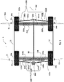
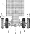
- FIG. 1 schematically illustrating a system 500 for adjusting width of a vehicle in which the system 500 is embedded, according to some embodiments of the invention.
- This system 500 is adapted to a novel four-wheel vehicle having a pair of front wheels 10a and 10b and a pair of rear wheels 20a and 20b.
- the system 500 is configured for being installed as a base unit of the vehicle over which a compartment for one or more passengers (including the driver) can be seated and carried.
- the system 500 includes two adjustment assemblies: a first adjustment assembly 100 and a second adjustment assembly 200 each connectable to a different pair of front and rear wheels 10a-10b and 20a-20b, respectively.
- the two adjustment assemblies 100 and 200 connect to one another for coordinating and synchronizing their operation via a connecting unit 50, which may be controlled by a controller 300 (see Figures 4A , 5A , 6A and 7A ).
- the coordinating of the two adjustment assemblies is optional each unit may be controlled separately
- each adjustment assembly 100 and 200 includes a foldable unit 110 and 210 and a tilting unit 120a and 120b or 220a and 220b, each unit connectable to the wheels 10a-10b and 20a-20b of the vehicle, respectively.
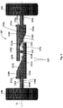
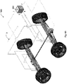
- Figures 2-3 show the first adjustment assembly 100 in details, although the second adjustment assembly 200 includes identical or similar components associated in the same or similar manner.
- the arrow 5 in all figures indicates the movement of forward direction.
- the foldable unit 110 of the first adjustment assembly 100 includes two adjustment members 110a and 110b which are movable elements each having a serrated portion 111a and 111b and a sloped portion 113a and 113b, respectively.
- the serrated portions 111a and 111b engage a cogwheel gear 150 (shortly referred to as gear 150 ) ensuring smooth transmission of movement to them by having the opposite lateral movement of the adjustment members 110a and 110b along the "Y" axis when the wheels are tilted and driven causing thereby the gear 150 to rotate and transmit torque thereof for causing lateral departing or converging of the adjustment members 110a and 110b.
- gear 150 cogwheel gear 150
- the movable adjustment members 110a and 110b can be prevented from folding or unfolding via safety stoppers 131a and 131b, which in this example are protrusions configured for being inserted to corresponding recesses 141a, 143a on one, and corresponding recesses on the other side (not shown) for stopper 131b where each adjustment member 110a/110b has two recesses each for locking the adjustment members 110a/110b in a different folded or unfolded position.
- safety stoppers 131a and 131b which in this example are protrusions configured for being inserted to corresponding recesses 141a, 143a on one, and corresponding recesses on the other side (not shown) for stopper 131b where each adjustment member 110a/110b has two recesses each for locking the adjustment members 110a/110b in a different folded or unfolded position.
- the driver may input a signal which will be received at a controller 300 of the system 500 causing the safety locks to be released while verifying that the vehicle is driven in low-speed which may be limited by a predefined speed range.
- the unlocking of the safety stoppers e.g.
- stoppers 131a and 131b while driving the vehicle will automatically and naturally cause the two adjustment members 110a and 110b and 210a and 210b of the front and rear wheels 10a-10b and 20a-20b, respectively, to laterally move along their respective "Y1" and "Y2" axes, while having the tilting units 120 and 220 causing the pairs of wheels 10a and 10b and 20a and 20b to tilt inwardly as shown in Figures 5A-5B for instance for having them converge into a folded distance therebetween for reducing the width of the vehicle.
- the driving of the vehicle (in a limited low-speed) in a converging angular positioning will automatically cause the released adjustment members 110a and 110b to move towards one another having the gear 150 enabling their lateral movement, causing thereby the entire vehicle to fold by reducing/shortening width thereof.
- the protrusion stoppers 131a and 131b may be inserted into the other recesses of the adjustment members 110a and 110b and 210a and 210b.
- the tilting unit 120 includes two telescopic members 120a and 120b each including a piston 122a and 122b, respectively coaxially inserted and movable in cylinders 121a and 121b.
- Each of the telescopic members 120a and 120b connects to a different wheel such as to wheels 10a and 10b, respectively, at one end thereof and to a connecting element such as a steering joint 190 (if connected to the front wheels 10a and 10b for instance) or a standard rear joint or connector 290 (if connected to the rear wheels 20a and 20b for instance).
- the steering joint 190 may be implemented as part of the vehicle steering mechanism or as separate unit for coordinating between the back and the front folding units or tilting units.
- each telescopic member 120a/120b or 220a/220b and the respective wheel 10a/10b or 20a/20b is via one or more connections such as through a protrusion connector 126a/126b configured for being inserted through an opening or recess of a corresponding wheel connecting plate 160a/160b.
- Each of the connecting plates 160a and 160b connects to wheels 10a and 10b respectively, via a connector 171a and 171b.
- non-mechanical mechanisms may be used for folding and unfolding the foldable unit and/or for coordinating the folding and unfolding of several adjustment assemblies of the system.
- the steering mechanism of the wheels which function at the normal driving mode is mechanically connected directly to the wheels.
- each connecting plate 160a and 160b includes several connecting elements 161a, 162a, 161b and 162b each having an opening therein wherein a first connecting element 161a and 161b is located off-center to the center of the wheel 10a and 10b axis "Y1", where an edge of each telescopic member such as 120a and 120b connects to a different first connecting element 161a and 161b respectively.
- This off-center connection allows the angular tilting of the wheels 10a and 10b caused by changing the length of the telescopic elements 120a and 120b angularly connecting thereto.
- Second connecting elements 162a and 162b are coaxial with "Y1" and connect to the edges of the adjustment members 110a and 110b for allowing these members to pull the wheels 10a and 10b towards each other along the "Y1" axis for decreasing distance therebetween and push the wheels 10a and 10b away from each other along the "Y1" axis for increasing distance therebetween.
- each telescopic member 120a/120b or 220a/220b and the respective wheel 10a/10b or 20a/20b is such that the angle between an axis of each telescopic member 120a/120b such as axes Z1a, Z1b, Z2a and Z2b and the wheels central axes Y1 and Y2 respectively: ⁇ 1 and ⁇ 2 is non-zero.
- the ⁇ 1 and ⁇ 2 may not be similar.
- the telescopic members 120a and 120b and 220a and 220b may be actuated via an actuator connected to the engine or battery of the vehicle for instance for pulling and pushing the pistons inside their respective cylinders.
- the tilting units 120 and 220 of the system 500 are controlled and operated by or through the controller 300 by, for example, electronically controlling the movements of their pistons for changing angular positioning of the wheels 10a-10b and 20a-20b.
- the tilting units 120 and 220 are actuated via one or more actuators, e.g. via the same motor actuator powered by a separate battery or via the vehicle's battery or any other energy source.
- the gear 150 can be used as a sensor for allowing sensing and indicating of the positioning and width of the vehicle at each given moment, by having a mechanism associated therewith counting the pitch angle (i.e. the number of rotations and angular positioning of the gear in respect to a predefined position thereover) and reporting the sensed width to the controller 300 of the system 500 for enabling to control the tilting units 120 and 220 according to the sensed current width.
- the pitch angle i.e. the number of rotations and angular positioning of the gear in respect to a predefined position thereover
- the system 500 and vehicle it is installed in are configured such that to fold and unfold the system 500 the driver or any other passenger is required to instruct an initiation of a folding/unfolding process via an interface of the controller 300 for instance via an initiation button.
- the controller 300 receives the initiation signal for folding the vehicle (e.g. for parking) it initially executes a safety procedure in which it verifies and/or causes the vehicle to drive within a limited speed range that is non-zero but slow enough to have the wheels tilted easily for adjusting the width.
- Another function executed in this preliminary safety procedure is releasing of the safety stoppers.
- the controller 300 operates the tilting units 120 and 220 of the system 500 during slow drive of the vehicle forward and optionally backward, depending on the desired driving direction and system 500 definitions.
- the tilting can be performed before releasing safety stoppers or at the same time.
- the tilting optionally done gradually as the vehicle is driven and therefore there is less resistance of the wheels (due to friction between the wheels and the road), as each pair of front and rear wheels 10a-10b and 20a-20b is tilted in opposite angular directions to converge for folding the vehicle or to diverge for unfolding thereof.
- the titling of the wheels 10a-10b and 20a-20b during the slow drive will cause, as mentioned above, the adjustment members 110a and 110b to move laterally in opposite directions away from or towards each other for respectively increasing or reducing the distance between each pair of wheels 10a-10b and 20a-20b.
- the controller 300 will cause the safety stoppers to lock for securing the fully folded/unfolded position.
- the adjustment assembly 100 also includes safety stoppers 132a and 132b for locking the telescopic members 120a and 120b respectively in the fully unfolded and optionally also in the folded positions by being configured for being inserted into corresponding one or more recesses such as recesses 142a and 142b of the telescopic members 120a and 120b.
- gear 150 can be optionally rotated by the vehicle's engine or a separate motor to support or cause the operation of the folding or unfolding.
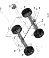
- Figures 4A-7C shows the system 500 in several positions.
- Figures 4A-4C show the system 500 in a converged and folded position in respect to a forward driving direction, in which the rear and front wheels 10a-20b of the vehicle are in a convergence titling positioning and the system 500 is in its maximal folded position, having its safety stoppers unlocked.
- Figures 5A-5C show the system 500 in a converged and unfolded position, in which the rear and front wheels 10a-20b of the vehicle are in a convergence titling positioning and the system 500 is still in an unfolded position ready for folding thereof, having its safety stoppers unlocked.
- Figures 6A-6C show the system 500 in a non-converged and unfolded position, in which the rear and front wheels 10a-20b of the vehicle are in a non-convergence titling positioning and the system 500 is still in an unfolded position ready for driving or after unfolding thereof, having its safety stoppers locked.
- Figures 7A-7C show the system 500 in a non-converged and folded position, in which the rear and front wheels 10a-20b of the vehicle are in a non-convergence titling positioning and the system 500 is still in a folded position ready for parking or after folding thereof, having its safety stoppers locked.
- the maximal width of the vehicle may be set according to standards and regulations of the specific geographical area as well as according to the design of the specific vehicle.
- the maximal width of the vehicle in the fully unfolded position is set to 1.60 meters (see Fig. 6C ) and the minimal width in the folded position is set to 1.00 meter (see Fig. 7C ).
- the minimum width may be set to 1.60 meters while the maximum width may be set to 2.20 meters in countries that only allow minimal four-wheel vehicle width of 1.60 meters.
- system 500 only allows locking onto two optional positions setting two optional vehicle's widths: a maximal one and a minimal one.
- the safety stoppers may fit into other additional recesses, for instance, for allowing one or more middle widths of the vehicle.
- the two adjustment assemblies 100 and 200 are connected to one another for coordinating their operations by having a drive shaft 50 connecting the two gears 150 and corresponding gear of the rear wheels (not shown) of the foldable units 110 and 210 of the two adjustment assemblies 100 and 200.
- the controller 300 also coordinates its operation of the telescopic members 120a-120b and 220a-220b of the tilting units 120 and 220 to ensure simultaneous and coordinated folding and unfolding of the adjustment assemblies 100 and 200.
- walls 11 and 12 may be installed such that they can move along with the wheels 10a-20b when having the distance there between adjusted, for example, by directly or indirectly connecting to the center of the wheels 10a-10b and 20a-20b.
- the system 500 is configured for being embedded in any vehicle type such as in an electric vehicle or non-electric one having an engine, for enabling width adjustment thereof, wherein the controller 300 may be powered via the battery of the vehicle or any other energy source.
- the system 500 requires no chassis to the vehicle, depending of course on the overall weight that can be achieved, which depends mainly on the weight and size of the passengers' compartment and engine/battery weight to be installed there over.
- the system 500 also includes means for limiting the steering angle (i.e. the angle of the steering wheels) during the folding and unfolding drive sessions for preventing the driver from diverting the steering wheel of the vehicle too sharply.
- the folding process is performed automatically not requiring the driver intervention, the driver may just stop the process in case of emergency.
- the controller 300 includes one or more computerized programmable control boxes that may control other mechanical elements for controlling the pistons of the telescopic elements of the tilting unit and also for controlling the locking and unlocking or releasing of the safety stoppers, for controlling the steering angle and the driving speed during folding and unfolding of the vehicle.
- the controller 300 may be powered via the battery of the vehicle.
- the width adjustment of the adjustment units of the system is done by actuating the tilting units thereof while the length adjustment of the foldable unit is done automatically during the drive of the vehicle caused by the tilting of the wheels in respect to their "Y" axis connecting their centers.
- the foldable units are the ones actuated (e.g. by having a motor rotating the drive shaft connecting the gears thereof) while the tilting is done automatically due to the off-center connection of the telescopic members to the wheels or by any other means.
- both the tilting units and the foldable units are actuated simultaneously via the controller using different or the same actuators for actuating each type of unit.
- one actuator such as a drive motor may be used for rotating the drive shaft connecting the foldable units' gears, while another actuator motor can be used for tilting the wheels by pulling and pushing the pistons in and out of their corresponding cylinders. In any case, however the vehicle has to be driven in a low non-zero speed during actuation.
- Fig. 8 is a flowchart schematically illustrating a process for folding a foldable vehicle having several adjustment assemblies as described above or in other configurations, according to some embodiments of the invention.
- the folding process includes first receiving an input signal at the controller of the system initiated by the driver or another user for initiating a folding drive session 61, e.g. by having the driver pressing a folding/unfolding real or virtual button at an interface operatively associated with the controller.
- a safety and initiation procedure 62 including at least one of the following steps: (i) speed limit validation and control, in which the controller (which may be associated with the power supply system of the vehicle) ensures that the vehicle is driven within a predefined range of speeds either by taking control over the power supply of the vehicle or by instructing the driver via the interface; and optionally (ii) steering angle limit validation and control, in which the controller (which may also be associated with the steering wheel system of the vehicle) ensures that the steering wheel angle does not exceed a predefined limit.
- the safety stoppers or any other locking mechanism that prevents folding of the vehicle are released 63 and the controller begins a coordinated tilting of the vehicles pairs of wheels 64 before or during the slow driving of the vehicle in a forward or backward direction causing thereby the pairs of wheels to have their front wheels converge when in a forward drive and diverge when in a backward drive, which will cause the foldable unit to fold and the distance between each pair of wheels to decrease.
- the distance between the wheels in each pair is optionally sensed 65 in real time via any one or more sensing mechanism such as by sensing the number of rotations done by a drive shaft mechanically connecting the adjustment assemblies of the system and/or by sensors located at the foldable unit's adjustment members and the like.
- the wheels are tilted before locking the safety stoppers when the vehicle is not in motion.
- the sensed information is received and processed at the controller or another computerized unit of the system and once a full folded position of the vehicle is identified 66 and the wheels are tilted back to a non-converged angular positioning 67 such as to an angle in which the wheels are parallel to the forward driving direction, and then the safety stoppers are locked 68.
- the safety limitations such as the speed and steering angle limitations may be disabled 69 to allow free normal drive of the vehicle.
- the wheels are tilted before locking the safety stoppers or at the same time.
- the unfolding process illustrated in Fig. 9 may include first receiving an input signal at the controller of the system initiated by the driver or another user for initiating an unfolding drive session 71, e.g. by having the driver pressing a folding/unfolding real or virtual button at an interface operatively associated with the controller. Once the controller receives this signal 71 it automatically executes a similar safety and initiation procedure 72 including at least one of the following steps: (i) speed limit validation and control; and optionally (ii) steering angle limit validation and control.
- the safety stoppers or any other locking mechanism that prevents unfolding of the vehicle are released 73 and the controller begins a coordinated tilting of the vehicles pairs of wheels 74 before or during the slow driving of the vehicle in a forward or backward direction causing thereby the pairs of wheels to have their front side diverge when in a forward drive and converge when in a backward drive, which will cause the foldable unit to unfold and the distance between each pair of wheels to increase.
- the distance between the wheels in each pair is optionally sensed 75 in real time in the same manner as it is sensed in the folding process.
- the sensed information is received and processed at the controller or another computerized unit of the system and once a full unfolded position of the vehicle is identified 76 the wheels are tilted back to a non-converged angular positioning 77 such as to an angle in which the wheels are parallel to the forward driving direction, and then the safety stoppers are locked 78.
- the safety limitations such as the speed and steering angle limitations may be disabled 79 to allow free normal drive of the vehicle.
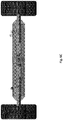
- Figures 10A-10B show an optional configuration of the system folding/extending mechanism, according to some embodiments of the invention: Fig. 10A shows top view of folding/extending mechanism in folded position; Fig. 10B shows a top view of folding/extending mechanism in the unfolded position.
- the folding/extending mechanism according to this embodiment is comprised of two arms 810A, 810B rotatabley connected one side to the vehicle front edge and on the other side to the front wheels, 10a, 10b.,via hinges 880A,B.
- the hinges are also connected to bar 870a,b which connects an extendable rods assembly 820a,b.
- the extendable rods assembly 820a,b is optionally driven by motor 860 through piston 850.
- the principle operation of the folding/extending mechanism is equivalent to the first solution in Figures 1-7 , the wheels are tilted by motor driven tilting mechanism or engine as described in the first solution, (not shown in these figures) causing by friction force, all the extendable/folding parts to move laterally in opposite directions away from or towards each other for respectively increasing or reducing the distance between each pair of wheels 10a-10b.
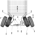
- Figures 11A-11B show the alternative configuration of the system folding/extending mechanism at different tilting positions, according to some embodiments of the invention:
- Fig. 11A shows top view of folding/extending mechanism in folded position and the wheels at strait position.;
- Fig. 11A shows top view of folding/extending mechanism in folded position and the wheels at tilted position.
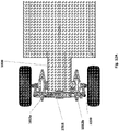
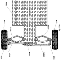
- Figures 12A-12C show another alternative configuration of the system folding/extending mechanism, according to some embodiments of the invention: Fig. 12A shows top view of folding/extending mechanism in folded position; Fig. 12B shows a top view of folding/ extending mechanism in the unfolded position
- Fig. 12C shows a top view of folding/extending mechanism in different folding position - folded and unfolded positions
- the folding/extending mechanism is comprised of two pentagon folding assemblies 1012a,b connected on one end to the edge of the vehicle front 1000 and on the end side to the front wheels, 10a , 10b.,via hinges.
- the hinges are also connected to bars 1020a, 1020b, which are rotatably interconnected by bar 1018.
- the pentagon folding assemblies are folded as seen in Fig. 12A and the bars 1020a, 1020bmove laterally in opposite directions away from or towards each other for respectively increasing or reducing the distance between each pair of wheels 10a-10b.
- the principle operation of the folding/extending mechanism is equivalent to the first solution in Figures 1-7 , the wheels are tilted by motor driven tilting mechanism or an engine as described in the first solution, (not shown in these figures) causing by friction force all the extendable parts to fold or move laterally in opposite directions away from or towards each other for respectively increasing or reducing the distance between each pair of wheels 10a-10b.
- Figures 13A-13B show configuration of the system bottom structure in the different folding position, according to some embodiments of the invention: Fig. 13A shows top view of the system bottom structure in folded position; Fig. 13B shows a top view of the system bottom structure in the unfolded position.
- the folding/extending mechanism is further applied on safety bottom platforms 2010,a,b, which fold and unfold along with the wheels, 10a,b, and 20 a, b
- Each safety bottom platforms is comprised of two surfaces fixed surfaces 2050 a, b and movable surfaces 2040 a, b which are slidable one above the other, constructing foldable platform.
- integrated wheels covers 2020 which move as one part with the surfaces.
Landscapes
- Engineering & Computer Science (AREA)
- Mechanical Engineering (AREA)
- Motorcycle And Bicycle Frame (AREA)
- Automatic Cycles, And Cycles In General (AREA)
- Steering-Linkage Mechanisms And Four-Wheel Steering (AREA)
Description
- The present invention generally relates to foldable/expandable vehicles and methods for folding and unfolding thereof and more particularly to width adjustment methods and systems and mechanisms for adjusting width of a vehicle.
- Foldable vehicles such as the HIRIKO™ foldable car (see link: http://www.youtube.com/watch?v-Qy3OgZYe1ZM), developed initially by MIT (Massachusetts Institute of Technology), are typically designed to save parking place and for easy maneuvering and parking in urban traffic. In the case of the HIRIKO™ foldable car, the folding mechanism is designed to adjust the length of the car almost by half (i.e. adjust the distance between the rear and front wheels) and optionally to also adjust its height. The length of the HIRIKO™ foldable car is adjusted by bringing the front wheels closer to the rear wheels closer together to fold the car into a folded position and farther from each other to bring the car to an unfolded position. The width of the HIRIKO™ foldable car however remains unchangeable. Since the HIRIKO™ foldable car has a small passenger(s) compartment fitting one driver passenger or more.
- According to the invention, there is provided an adjustment assembly for changing width of a vehicle that has at least one pair of wheels, where the adjustment assembly is embedded in the vehicle and is connectable to a pair of front, middle or rear wheels thereof. The adjustment assembly includes, inter alia: (i) a foldable unit connectable to the pair of wheels of the vehicle, configured for changing its overall length along a predefined axis "Y" connecting the centers of the pair of wheels, for adjusting a distance between the pair of wheels it connects to; and (ii) a tilting unit operatively associated with the pair of wheels of the vehicle to which the foldable unit connects. The tilting unit is configured for changing angular positioning of the pair of wheels in respect to the "Y" axis, during driving of the vehicle when the vehicle is folding or unfolding.
- The invention lies in an adjustment assembly according to
claim 1. Particular embodiments of this assembly are further defined in the dependent claims. - The folding/unfolding is performed during driving of the vehicle wherein said tilting unit and/or said foldable unit is controllable via a controller for operating thereof.
-
-
Fig. 1 shows a top view of a system for adjusting width of a foldable vehicle, wherein the system includes, inter alia, two adjustment assemblies operatively connected to one another, configured for changing the width of the vehicle, according to some embodiments of the present invention. -
Fig. 2 shows a front view of one of the adjustment assemblies of the system of the vehicle, according to some embodiments of the present invention. -
Fig. 3 shows an exploded view of one of the adjustment assemblies of the system, according to some embodiments of the present invention. -
Figures 4A-4C show the system in a converged and folded position, in which the rear and front wheels of the vehicle are in a convergence titling positioning and the system is in its maximal folded position ready for opening thereof, having its safety stoppers unlocked, according to some embodiments of the invention:Fig. 4A shows an isometric view of the system in the converged and folded position;Fig. 4B shows a top view of the system in the converged and folded position; andFig. 4C shows a front view of the system in the converged and folded position. -
Figures 5A-5C show the system in a converged and unfolded position, in which the rear and front wheels of the vehicle are in a convergence titling positioning and the system is still in an unfolded position ready for folding thereof, having its safety stoppers unlocked, according to some embodiments of the invention:Fig. 5A shows an isometric view of the system in the converged and unfolded position;Fig. 5B shows a top view of the system in the converged and unfolded position; andFig. 5C shows a front view of the system in the converged and unfolded position. -
Figures 6A-6C show the system in a non-converged and unfolded position, in which the rear and front wheels of the vehicle are in a non-convergence titling positioning and the system is in an unfolded position ready for driving or after unfolding thereof, having its safety stoppers locked according to some embodiments of the invention:Fig. 6A shows an isometric view of the system in the non-converged and unfolded position;Fig. 6B shows a top view of the system in the non-converged and unfolded position; andFig. 6C shows a front view of the system in the non-converged and unfolded position. -
Figures 7A-7C show the system in a non-converged and folded/constrict position, of the rear and front vehicle wheels are in a non-convergence titling positioning and the system is in a folded position ready for parking mode or after folding thereof, having its safety stoppers locked, according to some embodiments of the invention:Fig. 7A shows an isometric view of the system in the non-converged and folded position;Fig. 7B shows a top view of the system in the non-converged and folded position; andFig. 7C shows a front view of the system in the non-converged and folded position. -
Fig. 8 is a flowchart, schematically illustrating a process of folding/constricting a foldable vehicle, according to some embodiments of the invention. -
Fig. 9 is a flowchart, schematically illustrating a process of unfolding/ extending a foldable vehicle, according to some embodiments of the invention. -
Figures 10A-10B show an optional configuration of the system folding/extending mechanism , according to some embodiments of the invention:Fig. 10A shows top view of folding/extendable mechanism in folded position;Fig. 10B shows a top view of folding/extending mechanism in the unfolded position; -
Figures 11A-11B show the alternative configuration of the system folding/extending mechanism (as shown inFigures 10A-10B ) at different tilting positions, according to some embodiments of the invention:Fig. 11A shows top view of folding/extending mechanism in folded (dark wheels) and unfolded (light wheels) positions and the wheels at strait position.; -
Fig. 11B shows top view of folding/extending mechanism in folded (the wheels are shown is dark color) and unfolded (the wheels are shown in light color) positions and the wheels at tilted position. -
Figures 12A-12C show an alternative configuration of the system folding/ extending mechanism, according to some embodiments of the invention:Fig. 12A shows top view of folding/collapsing mechanism in folded position;Fig. 12B shows a top view of folding/collapsing mechanism in the unfolded position; -
Fig. 12C shows a top view of folding/collapsing mechanism in different folding position, folded (the wheels are shown in dark color) and unfolded (the wheels are shown in light color) positions -
Figures 13A-13B show configuration of the system bottom structure in the different folding position, according to some embodiments of the invention:Fig. 13A shows top view of the system bottom structure in folded position;Fig. 13B shows a top view of the system bottom structure in the unfolded position; - In the following detailed description of various embodiments, reference is made to the accompanying drawings that form a part thereof, and in which are shown by way of illustration specific embodiments in which the invention may be practiced. It is understood that other embodiments may be utilized and structural changes may be made without departing from the scope of the present invention.
- The present invention, in some embodiments thereof, provides systems methods and mechanisms such as adjustment assemblies for adjusting width of a vehicle as well as providing a foldable vehicle having a system including one or more of these mechanisms embedded therein as part of the vehicle itself. The foldable vehicle is designed to fold by decreasing width thereof, i.e. distance between each pair of rear and front for taking up fewer parking spaces and/or for easier maneuvering through urban narrow roads.
- The system includes one or more adjustment assemblies each is a mechanical mechanism that connects to a pair of front/rear/middle wheels of a foldable vehicle for enabling this vehicle to be folded and unfolded for changing its overall width, where the system is embedded in the foldable vehicle as integral part thereof.
- The adjustment assembly connects to a pair of wheels (e.g. front or rear wheels) of the vehicle and includes: (i) a foldable unit connectable to the pair wheels of the vehicle, which is configured for adjusting its overall width, for changing a distance between the pair of wheels it connects to over an axis "Y" between the centers of the wheels; and (ii) a tilting unit operatively associated with the pair of wheels of the vehicle to which the foldable unit connects, wherein the tilting unit is configured for tilting of a single wheel or a pair of wheels (i.e. changing the angular positioning in respect to the "Y" axis) during driving of the vehicle when folded or unfolded.
- The adjustment assembly is configured such that once the driver orders to fold or unfold the vehicle (depending on its condition at the time) the tilting unit and/or the foldable unit is automatically operated while the vehicle is driven in a limited speed for folding or unfolding thereof in a smooth and comfortable manner, by having the wheels gradually tilted during the slow drive (during the folding process) to one or more desired angular positions in respect to the "Y" axis and the foldable unit fold/unfold in coordination with the tilting of the wheels. Optionally, the tilting operation may be performed when the vehicle is not moving, before starting the folding process.
- Optionally, the wheels are not tilted gradually, but are remain at the same titling angle during the folding process.
- The tilting unit may include extendible elements that are angularly positioning in respect to the "Y" axis, where each element may connect to a different wheel of the pair. Each extendible element (such as a telescopic member that can be folded and unfolded to change its length) connects to a separate rear/front wheel, such that once these extendible elements are actuated to extend or fold thereof, they cause the front/rear wheels to tilt to a predefined angular positioning while the vehicle (and the wheels thereof) is driven allowing the width to be changed gradually and smoothly during the drive due to the tilt of the wheels.
- The titling unit may be implemented, partly as an inner unit integrated with in the wheel, optionally using an engine.
- The titling unit may be implemented, by mechanical mechanism directly controlling the tilting on the wheels. Alternatively the titling unit may be implemented, by electrical mechanism, using remote controller.
- According to some embodiments, the foldable unit includes one or more foldable members that are laterally connected to the pair of wheels over the "Y" axis thereof, such that when the vehicle is driven and the pair of wheels are tilted by the tilting unit, these one or more members will automatically extend or shorten and thereby allow stabilized extension or shortening of the vehicle's width.
- Since mechanisms such as these can be connected to the rear and front wheels of a vehicle they can be used to adjust the width of the vehicle rather than its length (i.e. adjusting the distance between the most distal edges of the right and left sides of the vehicle rather than the distance between the most distal edges of the front and back sides of the vehicle).
- According to some embodiments, the system for adjusting the width of a vehicle includes multiple adjustment assemblies: one adjustment assembly for each pair of front and rear wheels (optionally in case of a longer vehicle other middle pairs of wheels are added each may connect to a corresponding adjustment assembly).
- According to some embodiments, the operation of all the adjustment assemblies of the system are controlled by a single centralized controller and can be coordinated and/or synchronized via one or more mechanical and/or electronic means. This means that the pairs of wheels can be brought closer to or farther from one another via their corresponding adjustment assemblies in a synchronized manner in which all are moved simultaneously at the same rate and in a coordinated manner.
- According to some embodiments of the invention, the length of the foldable unit of each adjustment assembly can be mechanically adjusted by for instance including one or more adjustment members such as a telescopic element or by laterally moving several elements from or to each other along the "Y" axis having parts thereof engaging and/or overlapping to enable changing the overall distance between one non-engaging edge of one member to another having these edges directly or indirectly connect to each of the pair of wheels for changing the distance therebetween by their movement. The laterally moving of the adjustment members along the "Y" axis can be controlled and carried out via a mechanical transmission mechanism controlled by the controller of the system. For example, each of two adjustment members includes a serrated portion that can be laterally moved by engaging a central gear (cog wheel), the wheel can be rotated by the controller using the battery of the vehicle as a power source and the vehicle's engine to actuate a drive shaft connecting to the gear for rotating thereof. Each adjustment member connects to the gear in an opposite manner such that a rotation of the same gear will cause opposite lateral movement of the adjustment members along the "Y" axis. In this way the rotation of the gear to one direction (e.g. counterclockwise) will cause the adjustment members to distance from each other and to the other direction (e.g. clockwise) to approach one another and thereby to increase and decrease their length and the distance between the wheels they connect to, respectively. This mechanical transmission mechanism using a gear for moving the adjustment members, is optional and any other transmission mechanism can be used.
- Additionally or alternatively, the tilting unit includes multiple telescopic members each directly or indirectly connecting to a different wheel at one end thereof such that the axis of each telescopic member can be angularly changed in respect to the "Y" axis. In this way, whenever the distance between the two wheels (e.g. rear or front) is adjusted by the foldable unit (e.g. via rotation of a gear actuating thereof) the span of each of the telescopic members is changed thereby simultaneously changing the tilting angle of the wheels by pulling or pushing them inwardly or outwardly causing them to tilt thereby.
- Reference is now made to
Figures 1 , 4A-4B, 5A-5B ,6A-6B and7A-7B, schematically illustrating asystem 500 for adjusting width of a vehicle in which thesystem 500 is embedded, according to some embodiments of the invention. Thissystem 500 is adapted to a novel four-wheel vehicle having a pair offront wheels rear wheels system 500 is configured for being installed as a base unit of the vehicle over which a compartment for one or more passengers (including the driver) can be seated and carried. - The
system 500 includes two adjustment assemblies: afirst adjustment assembly 100 and asecond adjustment assembly 200 each connectable to a different pair of front andrear wheels 10a-10b and 20a-20b, respectively. - The two
adjustment assemblies unit 50, which may be controlled by a controller 300 (seeFigures 4A ,5A ,6A and7A ). The coordinating of the two adjustment assemblies is optional each unit may be controlled separately - As illustrated in
Figures 1-7C , eachadjustment assembly foldable unit tilting unit wheels 10a-10b and 20a-20b of the vehicle, respectively.Figures 2-3 show thefirst adjustment assembly 100 in details, although thesecond adjustment assembly 200 includes identical or similar components associated in the same or similar manner. - The
arrow 5 in all figures indicates the movement of forward direction. - According to some embodiments, the
foldable unit 110 of thefirst adjustment assembly 100 includes twoadjustment members serrated portion portion serrated portions adjustment members gear 150 to rotate and transmit torque thereof for causing lateral departing or converging of theadjustment members - As illustrated in
Figures 2-3 , themovable adjustment members safety stoppers recesses stopper 131b where eachadjustment member 110a/110b has two recesses each for locking theadjustment members 110a/110b in a different folded or unfolded position. - Once the driver wishes to cause the vehicle to fold for instance for parking thereof or for driving narrow roads or navigate through heavy traffic, he/she may input a signal which will be received at a
controller 300 of thesystem 500 causing the safety locks to be released while verifying that the vehicle is driven in low-speed which may be limited by a predefined speed range. The unlocking of the safety stoppers (e.g. stoppers adjustment members rear wheels 10a-10b and 20a-20b, respectively, to laterally move along their respective "Y1" and "Y2" axes, while having the tiltingunits wheels Figures 5A-5B for instance for having them converge into a folded distance therebetween for reducing the width of the vehicle. The driving of the vehicle (in a limited low-speed) in a converging angular positioning will automatically cause the releasedadjustment members gear 150 enabling their lateral movement, causing thereby the entire vehicle to fold by reducing/shortening width thereof. - Once the vehicle is folded, the
protrusion stoppers adjustment members - It is clear to see in
Figures 2-3 that a counterclockwise rotation of thegear 150 will be caused when theadjustment members wheels gear 150 is caused when theadjustment members wheels - As illustrated in details in
Figures 2-3 , thetilting unit 120 includes twotelescopic members piston cylinders telescopic members wheels front wheels rear wheels telescopic member 120a/120b or 220a/220b and therespective wheel 10a/10b or 20a/20b is via one or more connections such as through aprotrusion connector 126a/126b configured for being inserted through an opening or recess of a correspondingwheel connecting plate 160a/160b. Each of the connectingplates wheels connector - According to some embodiments of the present invention, the steering mechanism of the wheels which function at the normal driving mode, is mechanically connected directly to the wheels.
- As shown in
Fig. 3 , each connectingplate elements element wheel element wheels telescopic elements elements adjustment members wheels wheels - The connection between each
telescopic member 120a/120b or 220a/220b and therespective wheel 10a/10b or 20a/20b is such that the angle between an axis of eachtelescopic member 120a/120b such as axes Z1a, Z1b, Z2a and Z2b and the wheels central axes Y1 and Y2 respectively: α1 and α2 is non-zero. In this example α1 = α2 and β1=β2 and optionally α1=α2=β1=β2 at each given moment. Optionally the α1 and α2 may not be similar. Thetelescopic members - The tilting
units system 500 are controlled and operated by or through thecontroller 300 by, for example, electronically controlling the movements of their pistons for changing angular positioning of thewheels 10a-10b and 20a-20b. - According to some embodiments, the tilting
units - According to some embodiments, the
gear 150 can be used as a sensor for allowing sensing and indicating of the positioning and width of the vehicle at each given moment, by having a mechanism associated therewith counting the pitch angle (i.e. the number of rotations and angular positioning of the gear in respect to a predefined position thereover) and reporting the sensed width to thecontroller 300 of thesystem 500 for enabling to control the tiltingunits - According to some embodiments, the
system 500 and vehicle it is installed in are configured such that to fold and unfold thesystem 500 the driver or any other passenger is required to instruct an initiation of a folding/unfolding process via an interface of thecontroller 300 for instance via an initiation button. Once thecontroller 300 receives the initiation signal for folding the vehicle (e.g. for parking) it initially executes a safety procedure in which it verifies and/or causes the vehicle to drive within a limited speed range that is non-zero but slow enough to have the wheels tilted easily for adjusting the width. Another function executed in this preliminary safety procedure, is releasing of the safety stoppers. These verifications and operations are carried out and controlled via thecontroller 300. Once the safety procedure is verified and done, thecontroller 300 operates the tiltingunits system 500 during slow drive of the vehicle forward and optionally backward, depending on the desired driving direction andsystem 500 definitions. Optionally the tilting can be performed before releasing safety stoppers or at the same time. The tilting optionally done gradually as the vehicle is driven and therefore there is less resistance of the wheels (due to friction between the wheels and the road), as each pair of front andrear wheels 10a-10b and 20a-20b is tilted in opposite angular directions to converge for folding the vehicle or to diverge for unfolding thereof. The titling of thewheels 10a-10b and 20a-20b during the slow drive will cause, as mentioned above, theadjustment members wheels 10a-10b and 20a-20b. At the end of the width adjustment thecontroller 300 will cause the safety stoppers to lock for securing the fully folded/unfolded position. - According to some embodiments, as illustrated in
Figures 2-3 , theadjustment assembly 100 also includessafety stoppers telescopic members recesses telescopic members - In alternative embodiment the
gear 150 can be optionally rotated by the vehicle's engine or a separate motor to support or cause the operation of the folding or unfolding. -
Figures 4A-7C shows thesystem 500 in several positions.Figures 4A-4C show thesystem 500 in a converged and folded position in respect to a forward driving direction, in which the rear andfront wheels 10a-20b of the vehicle are in a convergence titling positioning and thesystem 500 is in its maximal folded position, having its safety stoppers unlocked.Figures 5A-5C show thesystem 500 in a converged and unfolded position, in which the rear andfront wheels 10a-20b of the vehicle are in a convergence titling positioning and thesystem 500 is still in an unfolded position ready for folding thereof, having its safety stoppers unlocked.Figures 6A-6C show thesystem 500 in a non-converged and unfolded position, in which the rear andfront wheels 10a-20b of the vehicle are in a non-convergence titling positioning and thesystem 500 is still in an unfolded position ready for driving or after unfolding thereof, having its safety stoppers locked.Figures 7A-7C show thesystem 500 in a non-converged and folded position, in which the rear andfront wheels 10a-20b of the vehicle are in a non-convergence titling positioning and thesystem 500 is still in a folded position ready for parking or after folding thereof, having its safety stoppers locked. - The maximal width of the vehicle may be set according to standards and regulations of the specific geographical area as well as according to the design of the specific vehicle. In this example, the maximal width of the vehicle in the fully unfolded position is set to 1.60 meters (see
Fig. 6C ) and the minimal width in the folded position is set to 1.00 meter (seeFig. 7C ). In other embodiments the minimum width may be set to 1.60 meters while the maximum width may be set to 2.20 meters in countries that only allow minimal four-wheel vehicle width of 1.60 meters. - In these embodiments the
system 500 only allows locking onto two optional positions setting two optional vehicle's widths: a maximal one and a minimal one. However, in other embodiments the safety stoppers may fit into other additional recesses, for instance, for allowing one or more middle widths of the vehicle. - As illustrated in
Figures 1 ,4A-4B ,5A-5B 6A-6B and7A-7B, the twoadjustment assemblies drive shaft 50 connecting the twogears 150 and corresponding gear of the rear wheels (not shown) of thefoldable units adjustment assemblies controller 300 also coordinates its operation of thetelescopic members 120a-120b and 220a-220b of the tiltingunits adjustment assemblies - In other embodiments other mechanism can be applied to coordinate the adjustment assemblies such as hydraulic/pneumatic systems for controlling the pistons or a single electric motor and the like.
- According to some embodiments, as illustrated in
Fig. 1 , since many countries regulations for a four-wheel vehicles require that the sides of the vehicles between the wheels will be walled,walls 11 and 12 (further shown inFigures 13A 13B ) may be installed such that they can move along with thewheels 10a-20b when having the distance there between adjusted, for example, by directly or indirectly connecting to the center of thewheels 10a-10b and 20a-20b. - According to some embodiments, the
system 500 is configured for being embedded in any vehicle type such as in an electric vehicle or non-electric one having an engine, for enabling width adjustment thereof, wherein thecontroller 300 may be powered via the battery of the vehicle or any other energy source. - According to some embodiments, the
system 500 requires no chassis to the vehicle, depending of course on the overall weight that can be achieved, which depends mainly on the weight and size of the passengers' compartment and engine/battery weight to be installed there over. - According to some embodiments, the
system 500 also includes means for limiting the steering angle (i.e. the angle of the steering wheels) during the folding and unfolding drive sessions for preventing the driver from diverting the steering wheel of the vehicle too sharply. The folding process is performed automatically not requiring the driver intervention, the driver may just stop the process in case of emergency. - According to some embodiments of the invention, the
controller 300 includes one or more computerized programmable control boxes that may control other mechanical elements for controlling the pistons of the telescopic elements of the tilting unit and also for controlling the locking and unlocking or releasing of the safety stoppers, for controlling the steering angle and the driving speed during folding and unfolding of the vehicle. Thecontroller 300, as mentioned above, may be powered via the battery of the vehicle. - In some embodiments the width adjustment of the adjustment units of the system is done by actuating the tilting units thereof while the length adjustment of the foldable unit is done automatically during the drive of the vehicle caused by the tilting of the wheels in respect to their "Y" axis connecting their centers. However, in other embodiments the foldable units are the ones actuated (e.g. by having a motor rotating the drive shaft connecting the gears thereof) while the tilting is done automatically due to the off-center connection of the telescopic members to the wheels or by any other means. In yet other embodiments of the invention, both the tilting units and the foldable units are actuated simultaneously via the controller using different or the same actuators for actuating each type of unit. For example, one actuator such as a drive motor may be used for rotating the drive shaft connecting the foldable units' gears, while another actuator motor can be used for tilting the wheels by pulling and pushing the pistons in and out of their corresponding cylinders. In any case, however the vehicle has to be driven in a low non-zero speed during actuation.
- Reference is now made to
Fig. 8 , which is a flowchart schematically illustrating a process for folding a foldable vehicle having several adjustment assemblies as described above or in other configurations, according to some embodiments of the invention. The folding process includes first receiving an input signal at the controller of the system initiated by the driver or another user for initiating afolding drive session 61, e.g. by having the driver pressing a folding/unfolding real or virtual button at an interface operatively associated with the controller. Once the controller receives thissignal 61 it automatically executes a safety andinitiation procedure 62 including at least one of the following steps: (i) speed limit validation and control, in which the controller (which may be associated with the power supply system of the vehicle) ensures that the vehicle is driven within a predefined range of speeds either by taking control over the power supply of the vehicle or by instructing the driver via the interface; and optionally (ii) steering angle limit validation and control, in which the controller (which may also be associated with the steering wheel system of the vehicle) ensures that the steering wheel angle does not exceed a predefined limit. Once the safety procedure is done and verified, the safety stoppers or any other locking mechanism that prevents folding of the vehicle are released 63 and the controller begins a coordinated tilting of the vehicles pairs ofwheels 64 before or during the slow driving of the vehicle in a forward or backward direction causing thereby the pairs of wheels to have their front wheels converge when in a forward drive and diverge when in a backward drive, which will cause the foldable unit to fold and the distance between each pair of wheels to decrease. The distance between the wheels in each pair is optionally sensed 65 in real time via any one or more sensing mechanism such as by sensing the number of rotations done by a drive shaft mechanically connecting the adjustment assemblies of the system and/or by sensors located at the foldable unit's adjustment members and the like. Optionally the wheels are tilted before locking the safety stoppers when the vehicle is not in motion. - The sensed information is received and processed at the controller or another computerized unit of the system and once a full folded position of the vehicle is identified 66 and the wheels are tilted back to a non-converged
angular positioning 67 such as to an angle in which the wheels are parallel to the forward driving direction, and then the safety stoppers are locked 68. The safety limitations such as the speed and steering angle limitations may be disabled 69 to allow free normal drive of the vehicle. Optionally the wheels are tilted before locking the safety stoppers or at the same time. - According to some embodiments, the unfolding process illustrated in
Fig. 9 , the unfolding process may include first receiving an input signal at the controller of the system initiated by the driver or another user for initiating an unfoldingdrive session 71, e.g. by having the driver pressing a folding/unfolding real or virtual button at an interface operatively associated with the controller. Once the controller receives thissignal 71 it automatically executes a similar safety andinitiation procedure 72 including at least one of the following steps: (i) speed limit validation and control; and optionally (ii) steering angle limit validation and control. Once the safety procedure is done and verified, the safety stoppers or any other locking mechanism that prevents unfolding of the vehicle are released 73 and the controller begins a coordinated tilting of the vehicles pairs ofwheels 74 before or during the slow driving of the vehicle in a forward or backward direction causing thereby the pairs of wheels to have their front side diverge when in a forward drive and converge when in a backward drive, which will cause the foldable unit to unfold and the distance between each pair of wheels to increase. The distance between the wheels in each pair is optionally sensed 75 in real time in the same manner as it is sensed in the folding process. The sensed information is received and processed at the controller or another computerized unit of the system and once a full unfolded position of the vehicle is identified 76 the wheels are tilted back to a non-convergedangular positioning 77 such as to an angle in which the wheels are parallel to the forward driving direction, and then the safety stoppers are locked 78. The safety limitations such as the speed and steering angle limitations may be disabled 79 to allow free normal drive of the vehicle. -
Figures 10A-10B show an optional configuration of the system folding/extending mechanism, according to some embodiments of the invention:Fig. 10A shows top view of folding/extending mechanism in folded position;Fig. 10B shows a top view of folding/extending mechanism in the unfolded position. The folding/extending mechanism according to this embodiment is comprised of twoarms 810A, 810B rotatabley connected one side to the vehicle front edge and on the other side to the front wheels, 10a, 10b.,via hinges 880A,B. The hinges are also connected to bar 870a,b which connects anextendable rods assembly 820a,b. Theextendable rods assembly 820a,b is optionally driven bymotor 860 throughpiston 850. The principle operation of the folding/extending mechanism is equivalent to the first solution inFigures 1-7 , the wheels are tilted by motor driven tilting mechanism or engine as described in the first solution, (not shown in these figures) causing by friction force, all the extendable/folding parts to move laterally in opposite directions away from or towards each other for respectively increasing or reducing the distance between each pair ofwheels 10a-10b. -
Figures 11A-11B show the alternative configuration of the system folding/extending mechanism at different tilting positions, according to some embodiments of the invention:Fig. 11A shows top view of folding/extending mechanism in folded position and the wheels at strait position.; -
Fig. 11A shows top view of folding/extending mechanism in folded position and the wheels at tilted position. -
Figures 12A-12C show another alternative configuration of the system folding/extending mechanism, according to some embodiments of the invention:Fig. 12A shows top view of folding/extending mechanism in folded position;Fig. 12B shows a top view of folding/ extending mechanism in the unfolded position -
Fig. 12C shows a top view of folding/extending mechanism in different folding position - folded and unfolded positions - The folding/extending mechanism according to this embodiment is comprised of two
pentagon folding assemblies 1012a,b connected on one end to the edge of thevehicle front 1000 and on the end side to the front wheels, 10a , 10b.,via hinges. The hinges are also connected tobars bar 1018. Through the folding process, the pentagon folding assemblies are folded as seen inFig. 12A and thebars 1020a, 1020bmove laterally in opposite directions away from or towards each other for respectively increasing or reducing the distance between each pair ofwheels 10a-10b. - The principle operation of the folding/extending mechanism is equivalent to the first solution in
Figures 1-7 , the wheels are tilted by motor driven tilting mechanism or an engine as described in the first solution, (not shown in these figures) causing by friction force all the extendable parts to fold or move laterally in opposite directions away from or towards each other for respectively increasing or reducing the distance between each pair ofwheels 10a-10b. -
Figures 13A-13B show configuration of the system bottom structure in the different folding position, according to some embodiments of the invention:Fig. 13A shows top view of the system bottom structure in folded position;Fig. 13B shows a top view of the system bottom structure in the unfolded position. - According to this embodiment, the folding/extending mechanism, is further applied on safety bottom platforms 2010,a,b, which fold and unfold along with the wheels, 10a,b, and 20 a, b Each safety bottom platforms is comprised of two surfaces fixed
surfaces 2050 a, b andmovable surfaces 2040 a, b which are slidable one above the other, constructing foldable platform. Optionally are integrated wheels covers 2020, which move as one part with the surfaces.
Claims (15)
- An adjustment assembly (100, 200) for changing width of a vehicle that has at least one pair of wheels (10a-10b, 20a-20b), said adjustment assembly is embedded in said vehicle and is connectable to a pair of front, middle or rear wheels of the vehicle, said adjustment assembly comprising:a) a foldable unit (110, 210) connectable to the wheels of said pair of wheels of the vehicle, said foldable unit having at least two portions coinciding with a predefined axis "Y" connecting centers of the pair of wheels, each of the at least two portions being connected to a corresponding wheel of the wheels of said pair of wheels; andb) a tilting unit (120, 220) operatively associated with the wheels of said pair of wheels of the vehicle, said tilting unit being configured for changing angular positioning of the wheels of said pair of wheels with respect to the axis "Y," said tilting unit being configured for changing the angular positioning of the wheels between a convergence tilting positioning of the wheels and a non-convergence tilting positioning of the wheels;wherein the at least two portions of the foldable unit are configured to move laterally along the axis "Y" when the wheels are in the convergence tilting positioning thereof, thereby adjusting a distance between the wheels of said pair of wheels during driving of the vehicle.
- The adjustment assembly of claim 1 wherein the change in the angular positioning of all wheels is synchronized.
- The adjustment assembly of claims 1 or 2, wherein the adjustment assembly is comprised of: two adjustment assemblies (100, 200), each connectable to a different pair of front and rear wheels, where the two adjustment assemblies are connect to one another for coordinating and synchronizing their operation via a connecting unit (50).
- The adjustment assembly of any one of the preceding claims, wherein the at least two portions of the foldable unit are configured to move along the axis "Y" inward and toward each other, thereby adjusting the distance between the wheels of said pair of wheels.
- The adjustment assembly of any one of the preceding claims, wherein the foldable unit includes adjustable members (110a, 110b) having serrated portion (111a, 111b) and sloped portion (113a, 113b), where the adjustable members are engaged at the serrated portion by a gear (150), such that when the wheels are in the convergence tilting positioning and the vehicle is driven, the gear rotate and transmit torque thereof for causing lateral departing or converging of the adjustment members; the movement of the adjustable members being optionally restricted via safety stoppers (131a, 131b); or the gear optionally comprises a sensor for indicating the width of said assembly.
- The adjustment assembly of claim 1, wherein the foldable unit includes pentagon collapsing assemblies (1012a, 1012b).
- The adjustment assembly of any one of the preceding claims further comprising security folding bottom platforms (2010a, 2010b) which are folding and unfolding along with the wheels, wherein the bottom platforms create continuous area between each pair of wheels.
- The adjustment assembly of any one of the preceding claims further comprising at least one motor for changing the angular positioning of the wheels.
- The adjustment assembly of any one of the preceding claims further comprising at least one motor for supporting the operation of the foldable unit.
- The adjustment assembly of any one of the preceding claims wherein the tilting unit includes two telescopic members (120a, 120b) each including a piston (122a, 122b), coaxially inserted and movable in cylinders (121a, 121b).
- The adjustment assembly of claim 10, wherein the telescopic members are actuated via an actuator connected to at least one engine of the vehicle for pulling and pushing the pistons inside their respective cylinder.
- The adjustment assembly of any one of the preceding claims, wherein both the tilting unit and the foldable unit are actuated simultaneously.
- The adjustment assembly of any one of the preceding claims, comprising a controller (300) configured for performing at least one of:(a) automatically executing a safety procedure of predefined rules, before starting the operation of the foldable unit including at least one of the following rules: (i) speed limit validation and control, ensures that the vehicle is driven within a predefined range of speeds either (ii) steering angle limit validation and control;(b) controlling the tilting unit;(c) controlling the foldable unit.
- The adjustment assembly of claim 1, further comprising sensing means for measuring distance between the wheels in each pair in real time during the adjustment of the distance between the wheels.
- The adjustment assembly of any one of the preceding claims, wherein the wheels are tilted gradually during the adjustment of the distance between the wheels.
Applications Claiming Priority (2)
| Application Number | Priority Date | Filing Date | Title |
|---|---|---|---|
| US201361890560P | 2013-10-14 | 2013-10-14 | |
| PCT/IL2014/050899 WO2015056266A1 (en) | 2013-10-14 | 2014-10-14 | Foldable vehicle, system and adjustment assembly thereof for adjusting width of a vehicle |
Publications (3)
| Publication Number | Publication Date |
|---|---|
| EP3206887A1 EP3206887A1 (en) | 2017-08-23 |
| EP3206887A4 EP3206887A4 (en) | 2018-08-29 |
| EP3206887B1 true EP3206887B1 (en) | 2022-07-20 |
Family
ID=52827754
Family Applications (1)
| Application Number | Title | Priority Date | Filing Date |
|---|---|---|---|
| EP14853373.0A Active EP3206887B1 (en) | 2013-10-14 | 2014-10-14 | Foldable vehicle, system and adjustment assembly thereof for adjusting width of a vehicle |
Country Status (6)
| Country | Link |
|---|---|
| US (1) | US10603955B2 (en) |
| EP (1) | EP3206887B1 (en) |
| JP (1) | JP6483844B2 (en) |
| CN (1) | CN107000478B (en) |
| ES (1) | ES2926205T3 (en) |
| WO (1) | WO2015056266A1 (en) |
Families Citing this family (10)
| Publication number | Priority date | Publication date | Assignee | Title |
|---|---|---|---|---|
| WO2018204526A1 (en) * | 2017-05-02 | 2018-11-08 | Gomaco Corporation | Freesteering system for mobile machines |
| US11083973B2 (en) * | 2017-11-09 | 2021-08-10 | Namero, LLC | Vehicle hopping system |
| US10717325B2 (en) * | 2018-01-05 | 2020-07-21 | Cnh Industrial America Llc | Drive line arrangement for a self-propelled agricultural product applicator |
| US11730073B2 (en) * | 2018-11-28 | 2023-08-22 | Agco Corporation | Mounting assembly for a steerable wheel with variable track width |
| US10870341B2 (en) * | 2019-01-28 | 2020-12-22 | National Taiwan Normal University | Electric vehicle and chassis thereof |
| KR102191528B1 (en) * | 2019-03-21 | 2020-12-15 | 한국기계연구원 | Mobile robot |
| USD952981S1 (en) | 2020-04-30 | 2022-05-24 | Rubbermaid Commercial Products Llc | Waste receptacle with a handle |
| US11873161B2 (en) | 2020-04-30 | 2024-01-16 | Rubbermaid Commercial Products Llc | Waste receptacles |
| CN111645777B (en) * | 2020-05-27 | 2021-06-15 | 农业农村部南京农业机械化研究所 | Wheeled agricultural robot with adaptive wheelbase adjustment function and its adjustment method |
| US11661117B2 (en) * | 2021-07-08 | 2023-05-30 | City Transformer Ltd. | Foldable vehicle |
Family Cites Families (28)
| Publication number | Priority date | Publication date | Assignee | Title |
|---|---|---|---|---|
| US243216A (en) * | 1881-06-21 | Cultivator | ||
| US3782491A (en) * | 1972-02-22 | 1974-01-01 | Trw Inc | Power steering system for adjustable track vehicles |
| FR2183416A5 (en) * | 1972-05-04 | 1973-12-14 | Bobard Emile | |
| US4109747A (en) * | 1976-05-13 | 1978-08-29 | American Hoist & Derrick Company | Steering mechanism |
| US4350222A (en) | 1980-03-24 | 1982-09-21 | Lutteke Martin T | Variable tread vehicle |
| JPH0443502U (en) * | 1990-08-14 | 1992-04-14 | ||
| US5489114A (en) * | 1994-09-29 | 1996-02-06 | Kidde Industries, Inc. | Tie rod extendable and retractable telescopic axle assembly |
| DE19933052C1 (en) | 1999-07-15 | 2000-11-23 | Daimler Chrysler Ag | Wheel suspension for a single-seat powered invalid carriage has a wheel carrier mounted with swing movement to the steering unit with lateral tracking adjustment on a guide rod |
| CA2284417A1 (en) | 1999-09-30 | 2001-03-30 | Shaul Ezer | Extendible and retractable wheel assembly for luggage |
| US6371243B1 (en) | 2001-02-13 | 2002-04-16 | Genie Industries, Inc. | True crab steering apparatus |
| US6827176B2 (en) * | 2003-01-07 | 2004-12-07 | Jlg Industries, Inc. | Vehicle with offset extendible axles and independent four-wheel steering control |
| WO2005056308A1 (en) | 2003-12-11 | 2005-06-23 | Singapore Technologies Kinetics Ltd | Wheel track adjustment system |
| US7387314B2 (en) * | 2004-02-11 | 2008-06-17 | White Robert E | Multi-configurable tractor |
| US7198278B2 (en) * | 2004-03-24 | 2007-04-03 | Genie Industries, Inc. | Vehicle support system |
| US7216896B1 (en) * | 2004-11-08 | 2007-05-15 | Robb Technologies, Llc | Heavy hauling system with hydraulic-powered extendable axles |
| JP4541201B2 (en) | 2005-03-24 | 2010-09-08 | 本田技研工業株式会社 | Car |
| NZ539543A (en) * | 2005-04-20 | 2008-02-29 | Graham John Mahy | Vehicle with adjustable track width and wheelbase |
| EP2050423A1 (en) * | 2007-07-16 | 2009-04-22 | Fundacion Tekniker | Wheelchair |
| US7954583B2 (en) | 2009-05-11 | 2011-06-07 | Deere & Company | Agricultural harvester rear axle arrangement for narrow transport |
| US7963361B2 (en) * | 2008-09-24 | 2011-06-21 | Deere & Company | Steering axle transport positioning structure and method |
| EP2388153B1 (en) * | 2010-05-17 | 2012-08-22 | Jaxa Networks | A vehicle having variable track |
| US20120029771A1 (en) * | 2010-07-30 | 2012-02-02 | Ryan Patrick Mackin | Steering control from scanned wheel information |
| US9434412B2 (en) * | 2010-08-23 | 2016-09-06 | Terex South Dakota, Inc. | Apparatuses and methods for steering a vehicle |
| CA2794484C (en) * | 2011-11-03 | 2020-09-22 | Awol Outdoors, Inc. | Fold-out trailer with retractable wheel assembly |
| JP2013212734A (en) * | 2012-03-30 | 2013-10-17 | Equos Research Co Ltd | Vehicle |
| US20160010546A1 (en) * | 2015-09-21 | 2016-01-14 | Electro-Motive Diesel, Inc. | Rocker cover assembly for engines |
| BE1022805B1 (en) * | 2015-02-18 | 2016-09-09 | Cnh Industrial Belgium Nv | Support frame for agricultural vehicle |
| US9968023B2 (en) * | 2016-06-07 | 2018-05-15 | Cnh Industrial America Llc | Systems and methods for adjusting wheel spacing of an agricultural implement |
-
2014
- 2014-10-14 EP EP14853373.0A patent/EP3206887B1/en active Active
- 2014-10-14 US US15/518,237 patent/US10603955B2/en active Active
- 2014-10-14 ES ES14853373T patent/ES2926205T3/en active Active
- 2014-10-14 WO PCT/IL2014/050899 patent/WO2015056266A1/en not_active Ceased
- 2014-10-14 CN CN201480084012.5A patent/CN107000478B/en active Active
- 2014-10-14 JP JP2017540339A patent/JP6483844B2/en active Active
Also Published As
| Publication number | Publication date |
|---|---|
| CN107000478B (en) | 2020-07-24 |
| US10603955B2 (en) | 2020-03-31 |
| JP6483844B2 (en) | 2019-03-13 |
| EP3206887A4 (en) | 2018-08-29 |
| JP2017534530A (en) | 2017-11-24 |
| WO2015056266A1 (en) | 2015-04-23 |
| CN107000478A (en) | 2017-08-01 |
| EP3206887A1 (en) | 2017-08-23 |
| ES2926205T3 (en) | 2022-10-24 |
| US20170305190A1 (en) | 2017-10-26 |
Similar Documents
| Publication | Publication Date | Title |
|---|---|---|
| US10603955B2 (en) | Foldable vehicle, system and adjustment assembly thereof for adjusting width of a vehicle | |
| AT518313B1 (en) | Electric balance vehicle | |
| CN103754256B (en) | A kind of have adjustable the electronlmobil steering swivel system and the control method that turn to pattern | |
| CN105579326B (en) | Transfer | |
| JP6382545B2 (en) | Steering device and vehicle equipped with the same | |
| CN105658503B (en) | Vehicle | |
| JP6452944B2 (en) | Steering device | |
| CN105636855B (en) | vehicle | |
| WO2015178269A1 (en) | Vehicle | |
| US20230322298A1 (en) | Vehicle steering system and vehicle having same | |
| JP2015217910A (en) | Control method of steering device and vehicle | |
| KR20140079127A (en) | Front view assisting device for vehicle | |
| JP6382544B2 (en) | Travel mode switching control method and vehicle | |
| CN203854710U (en) | Steering column mechanism applied to vehicle and vehicle with steering column mechanism | |
| JPH1029547A (en) | Steering control device | |
| WO2016121677A1 (en) | Steering device and vehicle equipped with same | |
| JP2015071363A (en) | Steering device | |
| JP6437189B2 (en) | Steering device and steering device system | |
| HK1241808A1 (en) | Foldable vehicle, system and adjustment assembly thereof for adjusting width of a vehicle | |
| HK1241808B (en) | Foldable vehicle, system and adjustment assembly thereof for adjusting width of a vehicle | |
| WO2016117585A1 (en) | Steering apparatus | |
| JP2003335158A (en) | Vehicle for handicapped person | |
| JP2016113042A (en) | Vehicle control method and vehicle | |
| JP2016099947A (en) | Vehicle surroundings monitoring device and vehicle control method |
Legal Events
| Date | Code | Title | Description |
|---|---|---|---|
| STAA | Information on the status of an ep patent application or granted ep patent |
Free format text: STATUS: THE INTERNATIONAL PUBLICATION HAS BEEN MADE |
|
| PUAI | Public reference made under article 153(3) epc to a published international application that has entered the european phase |
Free format text: ORIGINAL CODE: 0009012 |
|
| STAA | Information on the status of an ep patent application or granted ep patent |
Free format text: STATUS: REQUEST FOR EXAMINATION WAS MADE |
|
| 17P | Request for examination filed |
Effective date: 20170427 |
|
| AK | Designated contracting states |
Kind code of ref document: A1 Designated state(s): AL AT BE BG CH CY CZ DE DK EE ES FI FR GB GR HR HU IE IS IT LI LT LU LV MC MK MT NL NO PL PT RO RS SE SI SK SM TR |
|
| AX | Request for extension of the european patent |
Extension state: BA ME |
|
| DAX | Request for extension of the european patent (deleted) | ||
| A4 | Supplementary search report drawn up and despatched |
Effective date: 20180727 |
|
| RIC1 | Information provided on ipc code assigned before grant |
Ipc: B60B 35/10 20060101ALI20180723BHEP Ipc: B60B 35/00 20060101AFI20180723BHEP |
|
| RIC1 | Information provided on ipc code assigned before grant |
Ipc: B60B 35/10 20060101ALI20211219BHEP Ipc: B60B 35/00 20060101AFI20211219BHEP |
|
| GRAP | Despatch of communication of intention to grant a patent |
Free format text: ORIGINAL CODE: EPIDOSNIGR1 |
|
| STAA | Information on the status of an ep patent application or granted ep patent |
Free format text: STATUS: GRANT OF PATENT IS INTENDED |
|
| INTG | Intention to grant announced |
Effective date: 20220203 |
|
| GRAS | Grant fee paid |
Free format text: ORIGINAL CODE: EPIDOSNIGR3 |
|
| GRAA | (expected) grant |
Free format text: ORIGINAL CODE: 0009210 |
|
| STAA | Information on the status of an ep patent application or granted ep patent |
Free format text: STATUS: THE PATENT HAS BEEN GRANTED |
|
| AK | Designated contracting states |
Kind code of ref document: B1 Designated state(s): AL AT BE BG CH CY CZ DE DK EE ES FI FR GB GR HR HU IE IS IT LI LT LU LV MC MK MT NL NO PL PT RO RS SE SI SK SM TR |
|
| REG | Reference to a national code |
Ref country code: GB Ref legal event code: FG4D |
|
| REG | Reference to a national code |
Ref country code: CH Ref legal event code: EP |
|
| REG | Reference to a national code |
Ref country code: NL Ref legal event code: FP |
|
| REG | Reference to a national code |
Ref country code: DE Ref legal event code: R096 Ref document number: 602014084360 Country of ref document: DE |
|
| REG | Reference to a national code |
Ref country code: AT Ref legal event code: REF Ref document number: 1505299 Country of ref document: AT Kind code of ref document: T Effective date: 20220815 |
|
| REG | Reference to a national code |
Ref country code: IE Ref legal event code: FG4D |
|
| REG | Reference to a national code |
Ref country code: ES Ref legal event code: FG2A Ref document number: 2926205 Country of ref document: ES Kind code of ref document: T3 Effective date: 20221024 |
|
| REG | Reference to a national code |
Ref country code: LT Ref legal event code: MG9D |
|
| PG25 | Lapsed in a contracting state [announced via postgrant information from national office to epo] |
Ref country code: SE Free format text: LAPSE BECAUSE OF FAILURE TO SUBMIT A TRANSLATION OF THE DESCRIPTION OR TO PAY THE FEE WITHIN THE PRESCRIBED TIME-LIMIT Effective date: 20220720 Ref country code: RS Free format text: LAPSE BECAUSE OF FAILURE TO SUBMIT A TRANSLATION OF THE DESCRIPTION OR TO PAY THE FEE WITHIN THE PRESCRIBED TIME-LIMIT Effective date: 20220720 Ref country code: PT Free format text: LAPSE BECAUSE OF FAILURE TO SUBMIT A TRANSLATION OF THE DESCRIPTION OR TO PAY THE FEE WITHIN THE PRESCRIBED TIME-LIMIT Effective date: 20221121 Ref country code: NO Free format text: LAPSE BECAUSE OF FAILURE TO SUBMIT A TRANSLATION OF THE DESCRIPTION OR TO PAY THE FEE WITHIN THE PRESCRIBED TIME-LIMIT Effective date: 20221020 Ref country code: LV Free format text: LAPSE BECAUSE OF FAILURE TO SUBMIT A TRANSLATION OF THE DESCRIPTION OR TO PAY THE FEE WITHIN THE PRESCRIBED TIME-LIMIT Effective date: 20220720 Ref country code: LT Free format text: LAPSE BECAUSE OF FAILURE TO SUBMIT A TRANSLATION OF THE DESCRIPTION OR TO PAY THE FEE WITHIN THE PRESCRIBED TIME-LIMIT Effective date: 20220720 Ref country code: FI Free format text: LAPSE BECAUSE OF FAILURE TO SUBMIT A TRANSLATION OF THE DESCRIPTION OR TO PAY THE FEE WITHIN THE PRESCRIBED TIME-LIMIT Effective date: 20220720 |
|
| REG | Reference to a national code |
Ref country code: AT Ref legal event code: MK05 Ref document number: 1505299 Country of ref document: AT Kind code of ref document: T Effective date: 20220720 |
|
| PG25 | Lapsed in a contracting state [announced via postgrant information from national office to epo] |
Ref country code: PL Free format text: LAPSE BECAUSE OF FAILURE TO SUBMIT A TRANSLATION OF THE DESCRIPTION OR TO PAY THE FEE WITHIN THE PRESCRIBED TIME-LIMIT Effective date: 20220720 Ref country code: IS Free format text: LAPSE BECAUSE OF FAILURE TO SUBMIT A TRANSLATION OF THE DESCRIPTION OR TO PAY THE FEE WITHIN THE PRESCRIBED TIME-LIMIT Effective date: 20221120 Ref country code: HR Free format text: LAPSE BECAUSE OF FAILURE TO SUBMIT A TRANSLATION OF THE DESCRIPTION OR TO PAY THE FEE WITHIN THE PRESCRIBED TIME-LIMIT Effective date: 20220720 Ref country code: GR Free format text: LAPSE BECAUSE OF FAILURE TO SUBMIT A TRANSLATION OF THE DESCRIPTION OR TO PAY THE FEE WITHIN THE PRESCRIBED TIME-LIMIT Effective date: 20221021 |
|
| REG | Reference to a national code |
Ref country code: DE Ref legal event code: R097 Ref document number: 602014084360 Country of ref document: DE |
|
| PG25 | Lapsed in a contracting state [announced via postgrant information from national office to epo] |
Ref country code: SM Free format text: LAPSE BECAUSE OF FAILURE TO SUBMIT A TRANSLATION OF THE DESCRIPTION OR TO PAY THE FEE WITHIN THE PRESCRIBED TIME-LIMIT Effective date: 20220720 Ref country code: RO Free format text: LAPSE BECAUSE OF FAILURE TO SUBMIT A TRANSLATION OF THE DESCRIPTION OR TO PAY THE FEE WITHIN THE PRESCRIBED TIME-LIMIT Effective date: 20220720 Ref country code: DK Free format text: LAPSE BECAUSE OF FAILURE TO SUBMIT A TRANSLATION OF THE DESCRIPTION OR TO PAY THE FEE WITHIN THE PRESCRIBED TIME-LIMIT Effective date: 20220720 Ref country code: CZ Free format text: LAPSE BECAUSE OF FAILURE TO SUBMIT A TRANSLATION OF THE DESCRIPTION OR TO PAY THE FEE WITHIN THE PRESCRIBED TIME-LIMIT Effective date: 20220720 Ref country code: AT Free format text: LAPSE BECAUSE OF FAILURE TO SUBMIT A TRANSLATION OF THE DESCRIPTION OR TO PAY THE FEE WITHIN THE PRESCRIBED TIME-LIMIT Effective date: 20220720 |
|
| PLBE | No opposition filed within time limit |
Free format text: ORIGINAL CODE: 0009261 |
|
| STAA | Information on the status of an ep patent application or granted ep patent |
Free format text: STATUS: NO OPPOSITION FILED WITHIN TIME LIMIT |
|
| PG25 | Lapsed in a contracting state [announced via postgrant information from national office to epo] |
Ref country code: SK Free format text: LAPSE BECAUSE OF FAILURE TO SUBMIT A TRANSLATION OF THE DESCRIPTION OR TO PAY THE FEE WITHIN THE PRESCRIBED TIME-LIMIT Effective date: 20220720 Ref country code: MC Free format text: LAPSE BECAUSE OF FAILURE TO SUBMIT A TRANSLATION OF THE DESCRIPTION OR TO PAY THE FEE WITHIN THE PRESCRIBED TIME-LIMIT Effective date: 20220720 Ref country code: EE Free format text: LAPSE BECAUSE OF FAILURE TO SUBMIT A TRANSLATION OF THE DESCRIPTION OR TO PAY THE FEE WITHIN THE PRESCRIBED TIME-LIMIT Effective date: 20220720 |
|
| REG | Reference to a national code |
Ref country code: CH Ref legal event code: PL |
|
| REG | Reference to a national code |
Ref country code: BE Ref legal event code: MM Effective date: 20221031 |
|
| 26N | No opposition filed |
Effective date: 20230421 |
|
| PG25 | Lapsed in a contracting state [announced via postgrant information from national office to epo] |
Ref country code: LU Free format text: LAPSE BECAUSE OF NON-PAYMENT OF DUE FEES Effective date: 20221014 Ref country code: AL Free format text: LAPSE BECAUSE OF FAILURE TO SUBMIT A TRANSLATION OF THE DESCRIPTION OR TO PAY THE FEE WITHIN THE PRESCRIBED TIME-LIMIT Effective date: 20220720 |
|
| PG25 | Lapsed in a contracting state [announced via postgrant information from national office to epo] |
Ref country code: LI Free format text: LAPSE BECAUSE OF NON-PAYMENT OF DUE FEES Effective date: 20221031 Ref country code: CH Free format text: LAPSE BECAUSE OF NON-PAYMENT OF DUE FEES Effective date: 20221031 |
|
| PG25 | Lapsed in a contracting state [announced via postgrant information from national office to epo] |
Ref country code: SI Free format text: LAPSE BECAUSE OF FAILURE TO SUBMIT A TRANSLATION OF THE DESCRIPTION OR TO PAY THE FEE WITHIN THE PRESCRIBED TIME-LIMIT Effective date: 20220720 |
|
| PG25 | Lapsed in a contracting state [announced via postgrant information from national office to epo] |
Ref country code: BE Free format text: LAPSE BECAUSE OF NON-PAYMENT OF DUE FEES Effective date: 20221031 |
|
| PG25 | Lapsed in a contracting state [announced via postgrant information from national office to epo] |
Ref country code: IE Free format text: LAPSE BECAUSE OF NON-PAYMENT OF DUE FEES Effective date: 20221014 |
|
| PG25 | Lapsed in a contracting state [announced via postgrant information from national office to epo] |
Ref country code: HU Free format text: LAPSE BECAUSE OF FAILURE TO SUBMIT A TRANSLATION OF THE DESCRIPTION OR TO PAY THE FEE WITHIN THE PRESCRIBED TIME-LIMIT; INVALID AB INITIO Effective date: 20141014 |
|
| PG25 | Lapsed in a contracting state [announced via postgrant information from national office to epo] |
Ref country code: CY Free format text: LAPSE BECAUSE OF FAILURE TO SUBMIT A TRANSLATION OF THE DESCRIPTION OR TO PAY THE FEE WITHIN THE PRESCRIBED TIME-LIMIT Effective date: 20220720 |
|
| PG25 | Lapsed in a contracting state [announced via postgrant information from national office to epo] |
Ref country code: MK Free format text: LAPSE BECAUSE OF FAILURE TO SUBMIT A TRANSLATION OF THE DESCRIPTION OR TO PAY THE FEE WITHIN THE PRESCRIBED TIME-LIMIT Effective date: 20220720 |
|
| PG25 | Lapsed in a contracting state [announced via postgrant information from national office to epo] |
Ref country code: BG Free format text: LAPSE BECAUSE OF FAILURE TO SUBMIT A TRANSLATION OF THE DESCRIPTION OR TO PAY THE FEE WITHIN THE PRESCRIBED TIME-LIMIT Effective date: 20220720 |
|
| PG25 | Lapsed in a contracting state [announced via postgrant information from national office to epo] |
Ref country code: MT Free format text: LAPSE BECAUSE OF FAILURE TO SUBMIT A TRANSLATION OF THE DESCRIPTION OR TO PAY THE FEE WITHIN THE PRESCRIBED TIME-LIMIT Effective date: 20220720 |
|
| PGFP | Annual fee paid to national office [announced via postgrant information from national office to epo] |
Ref country code: NL Payment date: 20251021 Year of fee payment: 12 |
|
| PG25 | Lapsed in a contracting state [announced via postgrant information from national office to epo] |
Ref country code: TR Free format text: LAPSE BECAUSE OF FAILURE TO SUBMIT A TRANSLATION OF THE DESCRIPTION OR TO PAY THE FEE WITHIN THE PRESCRIBED TIME-LIMIT Effective date: 20220720 |
|
| PGFP | Annual fee paid to national office [announced via postgrant information from national office to epo] |
Ref country code: DE Payment date: 20251021 Year of fee payment: 12 |
|
| PGFP | Annual fee paid to national office [announced via postgrant information from national office to epo] |
Ref country code: GB Payment date: 20251024 Year of fee payment: 12 |
|
| PGFP | Annual fee paid to national office [announced via postgrant information from national office to epo] |
Ref country code: IT Payment date: 20251024 Year of fee payment: 12 |
|
| PGFP | Annual fee paid to national office [announced via postgrant information from national office to epo] |
Ref country code: FR Payment date: 20251030 Year of fee payment: 12 |
|
| PGFP | Annual fee paid to national office [announced via postgrant information from national office to epo] |
Ref country code: ES Payment date: 20251210 Year of fee payment: 12 |