EP3206651B1 - Bath tub lifter - Google Patents
Bath tub lifter Download PDFInfo
- Publication number
- EP3206651B1 EP3206651B1 EP15784166.9A EP15784166A EP3206651B1 EP 3206651 B1 EP3206651 B1 EP 3206651B1 EP 15784166 A EP15784166 A EP 15784166A EP 3206651 B1 EP3206651 B1 EP 3206651B1
- Authority
- EP
- European Patent Office
- Prior art keywords
- bearing
- scissor
- elements
- bath tub
- journal
- Prior art date
- Legal status (The legal status is an assumption and is not a legal conclusion. Google has not performed a legal analysis and makes no representation as to the accuracy of the status listed.)
- Active
Links
Images





Classifications
-
- A—HUMAN NECESSITIES
- A61—MEDICAL OR VETERINARY SCIENCE; HYGIENE
- A61G—TRANSPORT, PERSONAL CONVEYANCES, OR ACCOMMODATION SPECIALLY ADAPTED FOR PATIENTS OR DISABLED PERSONS; OPERATING TABLES OR CHAIRS; CHAIRS FOR DENTISTRY; FUNERAL DEVICES
- A61G7/00—Beds specially adapted for nursing; Devices for lifting patients or disabled persons
- A61G7/10—Devices for lifting patients or disabled persons, e.g. special adaptations of hoists thereto
- A61G7/1001—Devices for lifting patients or disabled persons, e.g. special adaptations of hoists thereto specially adapted for specific applications
- A61G7/1003—Devices for lifting patients or disabled persons, e.g. special adaptations of hoists thereto specially adapted for specific applications mounted on or in combination with a bath-tub
-
- A—HUMAN NECESSITIES
- A47—FURNITURE; DOMESTIC ARTICLES OR APPLIANCES; COFFEE MILLS; SPICE MILLS; SUCTION CLEANERS IN GENERAL
- A47K—SANITARY EQUIPMENT; ACCESSORIES THEREFOR, e.g. TOILET ACCESSORIES
- A47K3/00—Baths; Showers; Appurtenances therefor
- A47K3/12—Separate seats or body supports
- A47K3/122—Seats
-
- B—PERFORMING OPERATIONS; TRANSPORTING
- B66—HOISTING; LIFTING; HAULING
- B66F—HOISTING, LIFTING, HAULING OR PUSHING, NOT OTHERWISE PROVIDED FOR, e.g. DEVICES WHICH APPLY A LIFTING OR PUSHING FORCE DIRECTLY TO THE SURFACE OF A LOAD
- B66F7/00—Lifting frames, e.g. for lifting vehicles; Platform lifts
- B66F7/06—Lifting frames, e.g. for lifting vehicles; Platform lifts with platforms supported by levers for vertical movement
- B66F7/065—Scissor linkages, i.e. X-configuration
Definitions
- the present invention relates to a bath tub lifter comprising a seat element which is raisable and lowerable by means of a scissor lift.
- Bath tub lifters of the type in question serve to transfer care-dependent persons, for instance old or handicapped persons, gently into a bath tub and to lift them out of this same.
- a bath tub lifter of this type is disclosed, for instance, in DE 10 2006 048 524 A1 .
- this known bath tub lifter for the raising and lowering of the seat element, two pairs of scissor legs, which can be raised up and spread by means of a lifting apparatus, are coupled to one another.
- the coupling is realized by means of diverse elements such as coupling parts, connecting parts and locking parts. This is labor-intensive and cost-intensive.
- a further, comparable bath tub lifter is known from DE 10 2005 048 642 A1 .
- DE 20 2006 012 777 U1 shows a, in this respect, comparable lifting apparatus in the form of a scissor-type lifting table.
- the object, and thus the technical problem, on which the present invention is based is to provide a bath tub lifter of the type in question which is light and functional, enables a particularly economical production, and at the same time ensures the necessary operating reliability.
- the bath tub lifter comprises a seat element and a lifting apparatus for raising and lowering the seat element between a lower operating end position and an upper operating end position, and a scissor lift arrangement having two pairs of scissor lifts with scissor elements, wherein, in the operative state, respectively two scissor elements are coupled to each other such that they are mutually pivotable about a bearing axis.
- a bearing inner element On an inner scissor element a bearing inner element, and on an outer scissor element a bearing outer element, is provided.
- the bearing is constructed such that the bearing inner element and the bearing outer element, when the inner scissor element and the outer scissor element are in an assembly angular position relative to each other, can be joined in the radial direction into a functional setting, in which the bearing inner element and the bearing outer element are oriented coaxially to the bearing axis.
- the scissor elements in the operative state, over an operating range between the lower operating end position and the upper operating end position, do not assume the assembly angular position relative to each other, so that a separation in the radial direction is prevented throughout the operating range by form closure.
- the radial joining ensures that a bending-up of scissor elements in the course of the assembly, as is necessary with an assembly in the axial direction, is no longer necessary.
- the scissor elements can therefore be made more rigid, and nevertheless lighter, by the choice of appropriate shaping and materials.
- the bearings can be made wider, moreover, so that the bearing forces can be handled even without additional bearing bushes. This enables a lesser number of parts.
- the design of the bearings such that the scissor elements in the operative state, over an operating range between the lower operating end position and the upper operating end position, do not assume the assembly angular position relative to each other, so that separation in the radial direction is prevented throughout the operating range by form closure, enables that no additional locking elements, such as circlips or locking pins or the like, have to be used.
- the bath tub lifter according to the invention is therefore light and functional, enables a particularly economical production, and at the same time ensures the necessary operating reliability.
- the bearing outer element is configured with a bearing sleeve having a bearing seat, arranged concentrically to the bearing axis, and two radial recesses of different tangential width, wherein the tangential width of the first recess corresponds to the diameter of the bearing seat, and the tangential width of the second recess is smaller than the tangential width of the first recess, and the bearing inner element is configured with a bearing journal, the outer diameter of which corresponds to the diameter of the bearing seat and which has at least one, preferably two, stop cams, which, when the inner scissor element and the outer scissor element are in an assembly angular position relative to each other, can pass through the second recess and, when the scissor elements in the operative state do not assume the assembly angular position relative to each other, prevent the separation in the radial direction by form closure.
- the bearing outer element can be configured with a journal arranged concentrically to the bearing axis, which journal is divided by a journal groove into two opposite journal segments, wherein the width of the journal groove corresponds to the width of the stop cam.
- the bearing outer element can additionally be configured with a locking cam, which extends from the bearing seat radially in the direction of the bearing axis, wherein the bearing journal has a turned groove, in which the locking cam engages when the bearing outer element and the bearing inner element are arranged coaxially to each other.
- the two outer scissor elements can respectively have a bearing outer element, and the two inner scissor elements a bearing inner element.
- the two outer scissor elements can additionally be combined to form an outer frame, the two inner scissor elements to form an inner frame.
- the inner frame can have at least one cross strut, which connects the two inner scissor elements and which prevents expansion and compression of the inner frame.
- the inner frame can have, for instance, a cross strut in the region of the bearing axis, which cross strut connects the two inner scissor elements.
- the outer frame can have stiffening corners, which likewise prevent expansion of the outer frame.
- the scissor elements, and the bearing inner elements and bearing outer elements configured in one piece with said scissor elements, can be produced from plastic in an injection molding process.
- Fig. 1 shows a bath tub lifter according to one embodiment of the invention.
- a seat element 1 having a seat part 2 and a backrest 3 can be raised and lowered by means of a lifting apparatus 4 in conjunction with a scissor lift arrangement 10.
- the lifting apparatus 4 and the scissor lift arrangement 10 are supported on a base plate 5, which can be placed, for instance, onto the bottom of a bath tub (not shown).
- a care-dependent person can be transferred gently into a bath tub and lifted out of this same.
- FIG. 2 A perspective view of the scissor lift arrangement 10 is shown in fig. 2 .
- the scissor lift arrangement 10 has an inner frame 20 and an outer frame 30.
- Fig. 3 shows the inner frame 20 comprising two inner scissor elements 21 and two bearing inner elements 120, which latter are respectively arranged on the, related to the inner frame 20, outward facing sides of the inner scissor elements 21.
- the two inner scissor elements 21 are connected by, all in all, four transverse members 22, 23, 24 and 25, such that the inner frame 20 is stably formed.
- the transverse member 24 is in this case realized as a cross strut in the region of the bearing axis.
- the inner frame 20, and thus the two inner scissor elements 21, are connected via rear bearings 26 to the base plate 5.
- the corresponding connection to the seat part 2 of the seat element 1 is realized via sliding elements 27.
- Fig. 7 shows in a perspective view the outer frame 30 comprising two outer scissor elements 31, which are connected by transverse members 32 and 33 such that the outer frame 30 is stably formed.
- the transverse members 32 and 33 are reinforced by stiffening corners 38.
- the outer frame 30 likewise possesses two rear bearings 36, which are connected to the seat part 2 of the seat element 1, and sliding elements 37, which are connected to the base plate 5.
- Fig. 1 shows the bath tub lifter, and thus also the scissor lift arrangement 10, in an upper operating end position, that is to say the position in which the seat element 1, in the operably mounted state of the bath tub lifter, assumes the maximum possible height.
- Fig. 13 shows the scissor lift arrangement 10 in a lower operating end position, that is to say the position which the scissor lift arrangement 10 assumes when the seat element 1 (not shown in fig. 13 ), in the operably mounted state of the bath tub lifter, assumes the lowest height.
- the mounting of the scissor lift arrangement 10 is described below, which mounting enables the inner frame 20 and the outer frame 30, and thus the two pairs of scissor lifts comprising the respective scissor elements in the form of, in each case, an inner scissor element 21 and an outer scissor element 31, to be mutually pivotable about a bearing axis.
- the relevant bearing elements that is to say the bearing inner elements 120 disposed on the outer side of the inner frame 20 on the inner scissor elements 21 and the bearing outer elements 130 disposed on the inner side of the outer frame 30 on the outer scissor elements 31, are arranged concentrically to the bearing axis and couple the inner scissor elements 21 and outer scissor elements 31, and thus the inner frame 20 and the outer frame 30.
- the bearing outer element 130 is configured with a bearing sleeve 131 comprising a bearing seat 132, arranged concentrically to the bearing axis, and two radial recesses 133, 134 of different tangential width, wherein the tangential width of the first recess 133 corresponds to the diameter of the bearing seat 132 and the tangential width of the second recess 134 is smaller than the tangential width of the first recess 133.
- the axial dimension of the second recess 134 is moreover smaller than that of the first recess 133.
- the bearing inner element 120 is configured with a bearing journal 121, the outer diameter of which corresponds to the diameter of the bearing seat 132 and which has two stop cams 122, which, when the inner scissor element 21 and the outer scissor element 31, and thus the inner frame 20 and the outer frame 30, are in an assembly angular position shown in fig. 10 , can pass through the second recess, as can be seen in particular from fig. 11 and fig. 12 , and, when the scissor elements 21, 31 in the operative state do not assume the assembly angular position relative to each other, prevent the separation in the radial direction by form closure, as can be seen in particular from fig. 14 .
- the projection which in the region of the smaller, second recess 134 of the bearing outer element 130 is configured opposite the bearing seat 132 locks the stop cams 122 in an angular position, different from the assembly angular position, between inner frame 20 and outer frame 30 such that the bearing journal 121 of the bearing inner element 120 in such an angular position, that is to say a different position than the assembly angular position, cannot exit the bearing outer element 130 in the radial direction, due to form closure.
- the bearing outer element 130 is configured with a journal 135 arranged concentrically to the bearing axis, which journal is divided by a journal groove 136 into two opposite journal segments 135A, 135B.
- the width of the journal groove 136 corresponds to the width of the stop cam 122.
- the journal segments 135A, 135B thus serve, on the one hand, to guide the stop cams 122 as the bearing inner element 120 and the bearing outer element 130 are radially joined together when the inner scissor element 21 and the outer scissor element 31, and thus the inner frame 20 and the outer frame 30, are in the assembly angular position (shown in fig.
- said form closure prevents the bearing journal 121 of the bearing inner element 120, when the inner scissor element 21 and the outer scissor element 31, and thus the inner frame 20 and the outer frame 30, are not in the assembly angular position (shown in fig. 10 ) relative to each other, from being able to exit from the bearing outer element 130 in the radial direction.
- an axial exiting of the bearing journal 121 of the bearing inner element 120 from the bearing outer element 130 is prevented by virtue of the fact that the inner frame 20 and the outer frame 30 are constructed such that they are appropriately resistant to deformation.
- This rigidity is in any case necessary, given the load bearing function of the scissor lift arrangement 10.
- the rigidity is achieved by a suitable choice of material and dimensioning of the inner scissor elements 21 and transverse members 22, 23, 24 and 25 of the inner frame 20, inclusive of the cross strut 24 in the region of the bearing axis, and of the outer scissor elements 31 of the outer frame 30, with the transverse members 32 and 33 reinforced by stiffening corners 38.
- the bearing outer element can also be configured such that a form closure is formed in the axial direction also.
- the bearing seat 132 of the bearing outer element 130 can have, for instance, a locking cam 139, which extends from the bearing seat 132 radially in the direction of the bearing axis (see figs. 17 to 19 ), and the bearing journal 121 of the bearing inner element 120 can have a corresponding turned groove 129 (see figs. 15 and 16 ), in which the locking cam 139 engages if the bearing outer element 130 and the bearing inner element 120 are arranged coaxially to each other (see fig. 19 ).
Landscapes
- Health & Medical Sciences (AREA)
- Public Health (AREA)
- General Health & Medical Sciences (AREA)
- Life Sciences & Earth Sciences (AREA)
- Veterinary Medicine (AREA)
- Animal Behavior & Ethology (AREA)
- Nursing (AREA)
- Epidemiology (AREA)
- Engineering & Computer Science (AREA)
- Geology (AREA)
- Mechanical Engineering (AREA)
- Structural Engineering (AREA)
- Devices For Medical Bathing And Washing (AREA)
- Sliding-Contact Bearings (AREA)
Description
- The present invention relates to a bath tub lifter comprising a seat element which is raisable and lowerable by means of a scissor lift.
- Bath tub lifters of the type in question serve to transfer care-dependent persons, for instance old or handicapped persons, gently into a bath tub and to lift them out of this same. A bath tub lifter of this type is disclosed, for instance, in
DE 10 2006 048 524 A1 . In this known bath tub lifter, for the raising and lowering of the seat element, two pairs of scissor legs, which can be raised up and spread by means of a lifting apparatus, are coupled to one another. The coupling is realized by means of diverse elements such as coupling parts, connecting parts and locking parts. This is labor-intensive and cost-intensive. - A further, comparable bath tub lifter is known from
DE 10 2005 048 642 A1 .DE 20 2006 012 777 U1 shows a, in this respect, comparable lifting apparatus in the form of a scissor-type lifting table. - From the trade, a product of Invacare GmbH, which is marketed under the brand name ORCA (registered trademark) and in which, advantageously, instead of a multiplicity of individual scissor components, two scissor frames, an inner scissor frame and an outer scissor frame, are provided, is known. In the course of the assembly, these two scissor frames are fitted one into the other so that, on the outer scissor frame, inwardly extending pins can be inserted into corresponding bores in the inner scissor frame and, in conjunction with bearing bushes, ensure a stable mounting, wherein an axial locking is effected by additional locking elements.
- The object, and thus the technical problem, on which the present invention is based is to provide a bath tub lifter of the type in question which is light and functional, enables a particularly economical production, and at the same time ensures the necessary operating reliability.
- This object is achieved by a bath tub lifter according to
patent claim 1. Advantageous embodiments of the invention according topatent claim 1 are defined in the subclaims. - The bath tub lifter according to the invention comprises a seat element and a lifting apparatus for raising and lowering the seat element between a lower operating end position and an upper operating end position, and a scissor lift arrangement having two pairs of scissor lifts with scissor elements, wherein, in the operative state, respectively two scissor elements are coupled to each other such that they are mutually pivotable about a bearing axis. On an inner scissor element a bearing inner element, and on an outer scissor element a bearing outer element, is provided. The bearing is constructed such that the bearing inner element and the bearing outer element, when the inner scissor element and the outer scissor element are in an assembly angular position relative to each other, can be joined in the radial direction into a functional setting, in which the bearing inner element and the bearing outer element are oriented coaxially to the bearing axis. The scissor elements in the operative state, over an operating range between the lower operating end position and the upper operating end position, do not assume the assembly angular position relative to each other, so that a separation in the radial direction is prevented throughout the operating range by form closure.
- The radial joining ensures that a bending-up of scissor elements in the course of the assembly, as is necessary with an assembly in the axial direction, is no longer necessary. The scissor elements can therefore be made more rigid, and nevertheless lighter, by the choice of appropriate shaping and materials. As a result of the radial assembly, the bearings can be made wider, moreover, so that the bearing forces can be handled even without additional bearing bushes. This enables a lesser number of parts. Moreover, the design of the bearings such that the scissor elements in the operative state, over an operating range between the lower operating end position and the upper operating end position, do not assume the assembly angular position relative to each other, so that separation in the radial direction is prevented throughout the operating range by form closure, enables that no additional locking elements, such as circlips or locking pins or the like, have to be used. The bath tub lifter according to the invention is therefore light and functional, enables a particularly economical production, and at the same time ensures the necessary operating reliability.
- In one embodiment of the invention, the bearing outer element is configured with a bearing sleeve having a bearing seat, arranged concentrically to the bearing axis, and two radial recesses of different tangential width, wherein the tangential width of the first recess corresponds to the diameter of the bearing seat, and the tangential width of the second recess is smaller than the tangential width of the first recess, and the bearing inner element is configured with a bearing journal, the outer diameter of which corresponds to the diameter of the bearing seat and which has at least one, preferably two, stop cams, which, when the inner scissor element and the outer scissor element are in an assembly angular position relative to each other, can pass through the second recess and, when the scissor elements in the operative state do not assume the assembly angular position relative to each other, prevent the separation in the radial direction by form closure.
- The bearing outer element can be configured with a journal arranged concentrically to the bearing axis, which journal is divided by a journal groove into two opposite journal segments, wherein the width of the journal groove corresponds to the width of the stop cam.
- The bearing outer element can additionally be configured with a locking cam, which extends from the bearing seat radially in the direction of the bearing axis, wherein the bearing journal has a turned groove, in which the locking cam engages when the bearing outer element and the bearing inner element are arranged coaxially to each other.
- The two outer scissor elements can respectively have a bearing outer element, and the two inner scissor elements a bearing inner element. The two outer scissor elements can additionally be combined to form an outer frame, the two inner scissor elements to form an inner frame. The inner frame can have at least one cross strut, which connects the two inner scissor elements and which prevents expansion and compression of the inner frame. Thus the inner frame can have, for instance, a cross strut in the region of the bearing axis, which cross strut connects the two inner scissor elements. The outer frame can have stiffening corners, which likewise prevent expansion of the outer frame.
- The scissor elements, and the bearing inner elements and bearing outer elements configured in one piece with said scissor elements, can be produced from plastic in an injection molding process.
- All the above-described embodiments, taken in isolation and in respective combinations, enable a particularly economical production and at the same time ensure the necessary operating reliability of a bath tub lifter which is light and functional.
- The invention is further explained below on the basis of illustrative embodiments with reference to the drawings, in which:
-
fig. 1 is a view of one embodiment of a bath tub lifter according to the invention, -
fig. 2 is a perspective representation of a scissor lift arrangement, -
fig. 3 is a perspective representation of an inner frame of the scissor lift arrangement according tofig. 2 , -
fig. 4 shows a rear bearing of the inner frame according tofig. 3 , -
fig. 5 shows a front sliding element of the inner frame according tofig. 3 , -
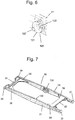
fig. 6 shows a bearing inner element which is provided on the inner frame according tofig. 3 , -
fig. 7 shows an outer frame of the scissor lift arrangement according tofig. 2 , -
fig. 8 shows a rear bearing of the outer frame according tofig. 7 , -
fig. 9 shows a bearing outer element which is arranged on the outer frame according tofig. 7 , -
fig. 10 shows the scissor lift arrangement according tofig. 2 with the outer frame according tofig. 7 and the inner frame according tofig. 3 in an assembly angular position, -
fig. 11 shows, as an enlarged detailed view fromfig. 10 , the bearing inner element and the bearing outer element in the assembly angular position in a radial view, -
fig. 12 is a representation according tofig. 11 in axial view, -
fig. 13 shows the scissor lift arrangement according tofig. 2 andfig. 10 in a lower operating end position, -
fig. 14 shows a representation, corresponding tofig. 12 , of the bearing inner element and bearing outer element in the lower operating end position according tofig. 13 , -
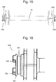
fig. 15 shows a second embodiment of a bearing inner element, -
fig. 16 is an enlarged representation of the bearing inner element according tofig. 15 , -
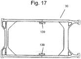
fig. 17 shows a top view of an outer frame with a second embodiment of bearing outer elements, which is compatible with the second embodiment of the bearing inner elements according tofig. 15 and fig. 16 , -
fig. 18 is an enlarged representation of the bearing outer element according tofig. 17 , and -
fig. 19 is a schematic representation for illustrating the functional relationship between the second embodiment of the bearing inner element and the second embodiment of the bearing outer element. -
Fig. 1 shows a bath tub lifter according to one embodiment of the invention. Aseat element 1 having aseat part 2 and abackrest 3 can be raised and lowered by means of alifting apparatus 4 in conjunction with ascissor lift arrangement 10. Thelifting apparatus 4 and thescissor lift arrangement 10 are supported on abase plate 5, which can be placed, for instance, onto the bottom of a bath tub (not shown). By raising and lowering of theseat element 1, a care-dependent person can be transferred gently into a bath tub and lifted out of this same. - A perspective view of the
scissor lift arrangement 10 is shown infig. 2 . Thescissor lift arrangement 10 has aninner frame 20 and anouter frame 30. -
Fig. 3 shows theinner frame 20 comprising twoinner scissor elements 21 and two bearinginner elements 120, which latter are respectively arranged on the, related to theinner frame 20, outward facing sides of theinner scissor elements 21. In the shown illustrative embodiment, the twoinner scissor elements 21 are connected by, all in all, fourtransverse members inner frame 20 is stably formed. Thetransverse member 24 is in this case realized as a cross strut in the region of the bearing axis. - The
inner frame 20, and thus the twoinner scissor elements 21, are connected viarear bearings 26 to thebase plate 5. The corresponding connection to theseat part 2 of theseat element 1 is realized via slidingelements 27. -
Fig. 7 shows in a perspective view theouter frame 30 comprising twoouter scissor elements 31, which are connected bytransverse members outer frame 30 is stably formed. Thetransverse members corners 38. Theouter frame 30 likewise possesses tworear bearings 36, which are connected to theseat part 2 of theseat element 1, and slidingelements 37, which are connected to thebase plate 5. On the inward facing sides of theouter scissor elements 31, that is to say pointing toward the inner side of theouter frame 30, are arrangedouter bearing elements 130. -
Fig. 1 shows the bath tub lifter, and thus also thescissor lift arrangement 10, in an upper operating end position, that is to say the position in which theseat element 1, in the operably mounted state of the bath tub lifter, assumes the maximum possible height. -
Fig. 13 shows thescissor lift arrangement 10 in a lower operating end position, that is to say the position which thescissor lift arrangement 10 assumes when the seat element 1 (not shown infig. 13 ), in the operably mounted state of the bath tub lifter, assumes the lowest height. - The mounting of the
scissor lift arrangement 10 is described below, which mounting enables theinner frame 20 and theouter frame 30, and thus the two pairs of scissor lifts comprising the respective scissor elements in the form of, in each case, aninner scissor element 21 and anouter scissor element 31, to be mutually pivotable about a bearing axis. The relevant bearing elements, that is to say the bearinginner elements 120 disposed on the outer side of theinner frame 20 on theinner scissor elements 21 and the bearingouter elements 130 disposed on the inner side of theouter frame 30 on theouter scissor elements 31, are arranged concentrically to the bearing axis and couple theinner scissor elements 21 andouter scissor elements 31, and thus theinner frame 20 and theouter frame 30. - As can be seen in particular from
fig. 9 , the bearingouter element 130 is configured with abearing sleeve 131 comprising abearing seat 132, arranged concentrically to the bearing axis, and tworadial recesses first recess 133 corresponds to the diameter of thebearing seat 132 and the tangential width of thesecond recess 134 is smaller than the tangential width of thefirst recess 133. In the shown illustrative embodiment, the axial dimension of thesecond recess 134 is moreover smaller than that of thefirst recess 133. - As can be seen in particular from
fig. 6 , the bearinginner element 120 is configured with abearing journal 121, the outer diameter of which corresponds to the diameter of thebearing seat 132 and which has twostop cams 122, which, when theinner scissor element 21 and theouter scissor element 31, and thus theinner frame 20 and theouter frame 30, are in an assembly angular position shown infig. 10 , can pass through the second recess, as can be seen in particular fromfig. 11 andfig. 12 , and, when thescissor elements fig. 14 . The projection which in the region of the smaller,second recess 134 of the bearingouter element 130 is configured opposite thebearing seat 132 locks thestop cams 122 in an angular position, different from the assembly angular position, betweeninner frame 20 andouter frame 30 such that thebearing journal 121 of the bearinginner element 120 in such an angular position, that is to say a different position than the assembly angular position, cannot exit the bearingouter element 130 in the radial direction, due to form closure. - The bearing
outer element 130 is configured with ajournal 135 arranged concentrically to the bearing axis, which journal is divided by ajournal groove 136 into twoopposite journal segments journal groove 136 corresponds to the width of thestop cam 122. Thejournal segments stop cams 122 as the bearinginner element 120 and the bearingouter element 130 are radially joined together when theinner scissor element 21 and theouter scissor element 31, and thus theinner frame 20 and theouter frame 30, are in the assembly angular position (shown infig. 10 ) relative to each other, and also help to ensure that, when theinner scissor element 21 and theouter scissor element 31, and thus theinner frame 20 and theouter frame 30, are not in the assembly angular position (shown infig. 10 ) relative to each other, thebearing journal 121 of the bearinginner element 120 cannot exit the bearingouter element 130 in the radial direction, due to form closure. - Of course, in addition to the above-described embodiment in which both form closure variants are realized, selectively only one of the two described, or a different form closure variant evident to the person skilled in the art, can also be used.
- As described, said form closure prevents the
bearing journal 121 of the bearinginner element 120, when theinner scissor element 21 and theouter scissor element 31, and thus theinner frame 20 and theouter frame 30, are not in the assembly angular position (shown infig. 10 ) relative to each other, from being able to exit from the bearingouter element 130 in the radial direction. - In the above-described embodiment of the invention, an axial exiting of the
bearing journal 121 of the bearinginner element 120 from the bearingouter element 130 is prevented by virtue of the fact that theinner frame 20 and theouter frame 30 are constructed such that they are appropriately resistant to deformation. This rigidity is in any case necessary, given the load bearing function of thescissor lift arrangement 10. In the above-described illustrative embodiment, the rigidity is achieved by a suitable choice of material and dimensioning of theinner scissor elements 21 andtransverse members inner frame 20, inclusive of thecross strut 24 in the region of the bearing axis, and of theouter scissor elements 31 of theouter frame 30, with thetransverse members corners 38. To the person skilled in the art, it will be obvious that various modifications hereto are possible. - In addition hereto, the bearing outer element can also be configured such that a form closure is formed in the axial direction also. To this end, the bearing
seat 132 of the bearingouter element 130 can have, for instance, alocking cam 139, which extends from thebearing seat 132 radially in the direction of the bearing axis (seefigs. 17 to 19 ), and thebearing journal 121 of the bearinginner element 120 can have a corresponding turned groove 129 (seefigs. 15 and 16 ), in which thelocking cam 139 engages if the bearingouter element 130 and the bearinginner element 120 are arranged coaxially to each other (seefig. 19 ).
Claims (10)
- A bath tub lifter, comprising
a seat element (1),
a lifting apparatus (4) for raising and lowering the seat element (1) between a lower operating end position and an upper operating end position, and
a scissor lift arrangement (10) having two pairs of scissor lifts with scissor elements (21, 31),
wherein, in the operative state, respectively two scissor elements (21, 31) are coupled to each other such that they are mutually pivotable about a bearing axis,
characterized
in that on an inner scissor element (21) a bearing inner element (120) is provided,
in that on an outer scissor element (31) a bearing outer element (130) is provided,
in that the bearing inner element (120) and the bearing outer element (130) are configured such that, when the inner scissor element (21) and the outer scissor element (31) are in an assembly angular position relative to each other, said bearing inner and outer elements (120, 130) can be joined in the radial direction into a functional setting, in which the bearing inner element (120) and the bearing outer element (130) are oriented coaxially to the bearing axis, and
in that the scissor elements (21, 31) do not in the operative state, over an operating range between the lower operating end position and the upper operating end position, assume the assembly angular position relative to each other and a separation in the radial direction is prevented by form closure. - The bath tub lifter as claimed in claim 1, characterized
in that
the bearing outer element (130) is configured with a bearing sleeve (131) having a bearing seat (132), arranged concentrically to the bearing axis, and two radial recesses (133, 134) of different tangential width, wherein the tangential width of the first recess (133) corresponds to the diameter of the bearing seat (132), and the tangential width of the second recess (134) is smaller than the tangential width of the first recess (133), and
in that the bearing inner element (120) is configured with a bearing journal (121), the outer diameter of which corresponds to the diameter of the bearing seat (132) and which has at least one, preferably two, stop cams (122), which, when the inner scissor element (21) and the outer scissor element (31) are in an assembly angular position relative to each other, can pass through the second recess (134) and, when the scissor elements (21, 31) in the operative state do not assume the assembly angular position relative to each other, prevent the separation in the radial direction by form closure. - The bath tub lifter as claimed in claim 2, characterized
in that
the bearing outer element (130) is configured with a journal (135) arranged concentrically to the bearing axis, which journal is divided by a journal groove (136) into two opposite journal segments (135A, 135B), and
in that the width of the journal groove (136) corresponds to the width of the stop cam (122). - The bath tub lifter as claimed in claim 2 or 3, characterized
in that
the bearing outer element (130) is configured with a locking cam (139), which extends from the bearing seat (132) radially in the direction of the bearing axis, and
in that the bearing journal (121) has a turned groove (129), in which the locking cam (139) engages when the bearing outer element (130) and the bearing inner element (120) are arranged coaxially to each other. - The bath tub lifter as claimed in one of the preceding claims 1 to 4, characterized
in that
the two outer scissor elements (31) respectively have a bearing outer element (130), and the two inner scissor elements (21) respectively have a bearing inner element (120). - The bath tub lifter as claimed in one of the preceding claims 1 to 5, characterized
in that
the two outer scissor elements (31) are combined to form an outer frame (30), the two inner scissor elements (21) to form an inner frame (20). - The bath tub lifter as claimed in claim 6, characterized
in that
the inner frame (20) has at least one cross strut (24), which connects the two inner scissor elements (21) and which prevents expansion and compression of the inner frame (20). - The bath tub lifter as claimed in claim 7, characterized
in that
the inner frame (20) has a cross strut (24) in the region of the bearing axis, which cross strut connects the two inner scissor elements (21). - The bath tub lifter as claimed in one of the preceding claims 6 to 8, characterized
in that
the outer frame (30) has stiffening corners (38), which prevent expansion of the outer frame (30). - The bath tub lifter as claimed in one of the preceding claims, characterized in that the scissor elements (21, 31), and the bearing inner elements (120) and bearing outer elements (130) configured in one piece with said scissor elements, are produced from plastic in an injection molding process.
Applications Claiming Priority (2)
| Application Number | Priority Date | Filing Date | Title |
|---|---|---|---|
| DE102014115040.6A DE102014115040B4 (en) | 2014-10-16 | 2014-10-16 | Badewannenlifter |
| PCT/IB2015/057734 WO2016059523A1 (en) | 2014-10-16 | 2015-10-09 | Bath tub lifter |
Publications (2)
| Publication Number | Publication Date |
|---|---|
| EP3206651A1 EP3206651A1 (en) | 2017-08-23 |
| EP3206651B1 true EP3206651B1 (en) | 2018-12-12 |
Family
ID=54337839
Family Applications (1)
| Application Number | Title | Priority Date | Filing Date |
|---|---|---|---|
| EP15784166.9A Active EP3206651B1 (en) | 2014-10-16 | 2015-10-09 | Bath tub lifter |
Country Status (5)
| Country | Link |
|---|---|
| US (1) | US10034809B2 (en) |
| EP (1) | EP3206651B1 (en) |
| CA (1) | CA2960363C (en) |
| DE (1) | DE102014115040B4 (en) |
| WO (1) | WO2016059523A1 (en) |
Families Citing this family (3)
| Publication number | Priority date | Publication date | Assignee | Title |
|---|---|---|---|---|
| DE102019131985B4 (en) * | 2019-11-26 | 2022-08-11 | Expresso Deutschland Gmbh | Mobile lightweight scissor lift table |
| CN222738148U (en) * | 2024-05-23 | 2025-04-11 | 士商(上海)机械有限公司 | Plastic electric auxiliary lifting equipment |
| USD1058203S1 (en) * | 2024-08-02 | 2025-01-21 | Yazhou Wang | Bath lift |
Family Cites Families (4)
| Publication number | Priority date | Publication date | Assignee | Title |
|---|---|---|---|---|
| DE202005021643U1 (en) * | 2005-10-11 | 2009-03-12 | Dentler Reha-Technik Gmbh & Co. Kg | Lifting device for bath filters for the disabled and infirm and sick persons |
| US7506385B2 (en) | 2005-10-18 | 2009-03-24 | Columbia Medical Manufacturing, Llc | Submersing bathing and transfer chair |
| DE202006012777U1 (en) * | 2006-08-19 | 2007-12-27 | Iht-Innovative Hebe Technik Gmbh | Lifting device in the form of a scissor lift |
| DE102006048524A1 (en) | 2006-10-13 | 2008-04-17 | Heckert Engineering Ag | Bath filter |
-
2014
- 2014-10-16 DE DE102014115040.6A patent/DE102014115040B4/en not_active Expired - Fee Related
-
2015
- 2015-10-09 US US15/518,799 patent/US10034809B2/en active Active
- 2015-10-09 WO PCT/IB2015/057734 patent/WO2016059523A1/en not_active Ceased
- 2015-10-09 EP EP15784166.9A patent/EP3206651B1/en active Active
- 2015-10-09 CA CA2960363A patent/CA2960363C/en active Active
Non-Patent Citations (1)
| Title |
|---|
| None * |
Also Published As
| Publication number | Publication date |
|---|---|
| CA2960363A1 (en) | 2016-04-21 |
| US20170231845A1 (en) | 2017-08-17 |
| EP3206651A1 (en) | 2017-08-23 |
| US10034809B2 (en) | 2018-07-31 |
| DE102014115040A1 (en) | 2016-04-21 |
| DE102014115040B4 (en) | 2018-01-18 |
| CA2960363C (en) | 2022-11-15 |
| WO2016059523A1 (en) | 2016-04-21 |
Similar Documents
| Publication | Publication Date | Title |
|---|---|---|
| US10034809B2 (en) | Bath tub lifter | |
| US11284708B2 (en) | Lifting table with height adjustment device | |
| EP2801504B1 (en) | Shelf for a roll container | |
| US8935822B2 (en) | Modular ramp construction and wedge elements herefore | |
| EP3145852B1 (en) | Vehicle lift | |
| CN104603044A (en) | Scissor lift table | |
| USD921862S1 (en) | Toilet seats | |
| WO2016180569A1 (en) | Lift for motor vehicles | |
| US835492A (en) | Caster. | |
| AU2025248691A1 (en) | Patient lift apparatus | |
| US7537237B2 (en) | Detachable wheelchair | |
| KR200485649Y1 (en) | Combination flat bench and table | |
| CN210471641U (en) | Dining chair for children | |
| KR200456446Y1 (en) | Supporting jig for heavy machinery tire wheel assembly | |
| PL429611A1 (en) | Closure assembly of a container, in particular for beverages | |
| USD985995S1 (en) | Hot base for induction cookware | |
| JP6748448B2 (en) | Lifting table | |
| US1208436A (en) | Table. | |
| WO2007088145A1 (en) | Improved pantograph lift | |
| US110402A (en) | Improvement in seat-hinges for school-desks and settees | |
| KR102093712B1 (en) | Automatic elevating device for restaurants | |
| US1146779A (en) | Elevating-truck. | |
| EP3177182B1 (en) | Improved chair with headrest | |
| KR20180065409A (en) | Motion bed comprising a rack and a pinion | |
| JP2015059007A (en) | Joint link and chain conveyor |
Legal Events
| Date | Code | Title | Description |
|---|---|---|---|
| STAA | Information on the status of an ep patent application or granted ep patent |
Free format text: STATUS: THE INTERNATIONAL PUBLICATION HAS BEEN MADE |
|
| PUAI | Public reference made under article 153(3) epc to a published international application that has entered the european phase |
Free format text: ORIGINAL CODE: 0009012 |
|
| STAA | Information on the status of an ep patent application or granted ep patent |
Free format text: STATUS: REQUEST FOR EXAMINATION WAS MADE |
|
| 17P | Request for examination filed |
Effective date: 20170418 |
|
| AK | Designated contracting states |
Kind code of ref document: A1 Designated state(s): AL AT BE BG CH CY CZ DE DK EE ES FI FR GB GR HR HU IE IS IT LI LT LU LV MC MK MT NL NO PL PT RO RS SE SI SK SM TR |
|
| AX | Request for extension of the european patent |
Extension state: BA ME |
|
| DAV | Request for validation of the european patent (deleted) | ||
| DAX | Request for extension of the european patent (deleted) | ||
| GRAP | Despatch of communication of intention to grant a patent |
Free format text: ORIGINAL CODE: EPIDOSNIGR1 |
|
| STAA | Information on the status of an ep patent application or granted ep patent |
Free format text: STATUS: GRANT OF PATENT IS INTENDED |
|
| INTG | Intention to grant announced |
Effective date: 20180720 |
|
| GRAS | Grant fee paid |
Free format text: ORIGINAL CODE: EPIDOSNIGR3 |
|
| GRAA | (expected) grant |
Free format text: ORIGINAL CODE: 0009210 |
|
| STAA | Information on the status of an ep patent application or granted ep patent |
Free format text: STATUS: THE PATENT HAS BEEN GRANTED |
|
| AK | Designated contracting states |
Kind code of ref document: B1 Designated state(s): AL AT BE BG CH CY CZ DE DK EE ES FI FR GB GR HR HU IE IS IT LI LT LU LV MC MK MT NL NO PL PT RO RS SE SI SK SM TR |
|
| REG | Reference to a national code |
Ref country code: GB Ref legal event code: FG4D |
|
| REG | Reference to a national code |
Ref country code: CH Ref legal event code: EP |
|
| REG | Reference to a national code |
Ref country code: AT Ref legal event code: REF Ref document number: 1075042 Country of ref document: AT Kind code of ref document: T Effective date: 20181215 |
|
| REG | Reference to a national code |
Ref country code: DE Ref legal event code: R096 Ref document number: 602015021518 Country of ref document: DE |
|
| REG | Reference to a national code |
Ref country code: IE Ref legal event code: FG4D |
|
| REG | Reference to a national code |
Ref country code: NL Ref legal event code: MP Effective date: 20181212 |
|
| REG | Reference to a national code |
Ref country code: LT Ref legal event code: MG4D |
|
| PG25 | Lapsed in a contracting state [announced via postgrant information from national office to epo] |
Ref country code: LT Free format text: LAPSE BECAUSE OF FAILURE TO SUBMIT A TRANSLATION OF THE DESCRIPTION OR TO PAY THE FEE WITHIN THE PRESCRIBED TIME-LIMIT Effective date: 20181212 Ref country code: HR Free format text: LAPSE BECAUSE OF FAILURE TO SUBMIT A TRANSLATION OF THE DESCRIPTION OR TO PAY THE FEE WITHIN THE PRESCRIBED TIME-LIMIT Effective date: 20181212 Ref country code: BG Free format text: LAPSE BECAUSE OF FAILURE TO SUBMIT A TRANSLATION OF THE DESCRIPTION OR TO PAY THE FEE WITHIN THE PRESCRIBED TIME-LIMIT Effective date: 20190312 Ref country code: ES Free format text: LAPSE BECAUSE OF FAILURE TO SUBMIT A TRANSLATION OF THE DESCRIPTION OR TO PAY THE FEE WITHIN THE PRESCRIBED TIME-LIMIT Effective date: 20181212 Ref country code: NO Free format text: LAPSE BECAUSE OF FAILURE TO SUBMIT A TRANSLATION OF THE DESCRIPTION OR TO PAY THE FEE WITHIN THE PRESCRIBED TIME-LIMIT Effective date: 20190312 Ref country code: FI Free format text: LAPSE BECAUSE OF FAILURE TO SUBMIT A TRANSLATION OF THE DESCRIPTION OR TO PAY THE FEE WITHIN THE PRESCRIBED TIME-LIMIT Effective date: 20181212 Ref country code: LV Free format text: LAPSE BECAUSE OF FAILURE TO SUBMIT A TRANSLATION OF THE DESCRIPTION OR TO PAY THE FEE WITHIN THE PRESCRIBED TIME-LIMIT Effective date: 20181212 |
|
| REG | Reference to a national code |
Ref country code: AT Ref legal event code: MK05 Ref document number: 1075042 Country of ref document: AT Kind code of ref document: T Effective date: 20181212 |
|
| PG25 | Lapsed in a contracting state [announced via postgrant information from national office to epo] |
Ref country code: RS Free format text: LAPSE BECAUSE OF FAILURE TO SUBMIT A TRANSLATION OF THE DESCRIPTION OR TO PAY THE FEE WITHIN THE PRESCRIBED TIME-LIMIT Effective date: 20181212 Ref country code: SE Free format text: LAPSE BECAUSE OF FAILURE TO SUBMIT A TRANSLATION OF THE DESCRIPTION OR TO PAY THE FEE WITHIN THE PRESCRIBED TIME-LIMIT Effective date: 20181212 Ref country code: AL Free format text: LAPSE BECAUSE OF FAILURE TO SUBMIT A TRANSLATION OF THE DESCRIPTION OR TO PAY THE FEE WITHIN THE PRESCRIBED TIME-LIMIT Effective date: 20181212 Ref country code: GR Free format text: LAPSE BECAUSE OF FAILURE TO SUBMIT A TRANSLATION OF THE DESCRIPTION OR TO PAY THE FEE WITHIN THE PRESCRIBED TIME-LIMIT Effective date: 20190313 |
|
| PG25 | Lapsed in a contracting state [announced via postgrant information from national office to epo] |
Ref country code: NL Free format text: LAPSE BECAUSE OF FAILURE TO SUBMIT A TRANSLATION OF THE DESCRIPTION OR TO PAY THE FEE WITHIN THE PRESCRIBED TIME-LIMIT Effective date: 20181212 |
|
| PG25 | Lapsed in a contracting state [announced via postgrant information from national office to epo] |
Ref country code: PL Free format text: LAPSE BECAUSE OF FAILURE TO SUBMIT A TRANSLATION OF THE DESCRIPTION OR TO PAY THE FEE WITHIN THE PRESCRIBED TIME-LIMIT Effective date: 20181212 Ref country code: PT Free format text: LAPSE BECAUSE OF FAILURE TO SUBMIT A TRANSLATION OF THE DESCRIPTION OR TO PAY THE FEE WITHIN THE PRESCRIBED TIME-LIMIT Effective date: 20190412 Ref country code: IT Free format text: LAPSE BECAUSE OF FAILURE TO SUBMIT A TRANSLATION OF THE DESCRIPTION OR TO PAY THE FEE WITHIN THE PRESCRIBED TIME-LIMIT Effective date: 20181212 Ref country code: CZ Free format text: LAPSE BECAUSE OF FAILURE TO SUBMIT A TRANSLATION OF THE DESCRIPTION OR TO PAY THE FEE WITHIN THE PRESCRIBED TIME-LIMIT Effective date: 20181212 |
|
| PG25 | Lapsed in a contracting state [announced via postgrant information from national office to epo] |
Ref country code: RO Free format text: LAPSE BECAUSE OF FAILURE TO SUBMIT A TRANSLATION OF THE DESCRIPTION OR TO PAY THE FEE WITHIN THE PRESCRIBED TIME-LIMIT Effective date: 20181212 Ref country code: IS Free format text: LAPSE BECAUSE OF FAILURE TO SUBMIT A TRANSLATION OF THE DESCRIPTION OR TO PAY THE FEE WITHIN THE PRESCRIBED TIME-LIMIT Effective date: 20190412 Ref country code: SM Free format text: LAPSE BECAUSE OF FAILURE TO SUBMIT A TRANSLATION OF THE DESCRIPTION OR TO PAY THE FEE WITHIN THE PRESCRIBED TIME-LIMIT Effective date: 20181212 Ref country code: EE Free format text: LAPSE BECAUSE OF FAILURE TO SUBMIT A TRANSLATION OF THE DESCRIPTION OR TO PAY THE FEE WITHIN THE PRESCRIBED TIME-LIMIT Effective date: 20181212 Ref country code: SK Free format text: LAPSE BECAUSE OF FAILURE TO SUBMIT A TRANSLATION OF THE DESCRIPTION OR TO PAY THE FEE WITHIN THE PRESCRIBED TIME-LIMIT Effective date: 20181212 |
|
| REG | Reference to a national code |
Ref country code: DE Ref legal event code: R097 Ref document number: 602015021518 Country of ref document: DE |
|
| PLBE | No opposition filed within time limit |
Free format text: ORIGINAL CODE: 0009261 |
|
| STAA | Information on the status of an ep patent application or granted ep patent |
Free format text: STATUS: NO OPPOSITION FILED WITHIN TIME LIMIT |
|
| PG25 | Lapsed in a contracting state [announced via postgrant information from national office to epo] |
Ref country code: AT Free format text: LAPSE BECAUSE OF FAILURE TO SUBMIT A TRANSLATION OF THE DESCRIPTION OR TO PAY THE FEE WITHIN THE PRESCRIBED TIME-LIMIT Effective date: 20181212 Ref country code: DK Free format text: LAPSE BECAUSE OF FAILURE TO SUBMIT A TRANSLATION OF THE DESCRIPTION OR TO PAY THE FEE WITHIN THE PRESCRIBED TIME-LIMIT Effective date: 20181212 Ref country code: SI Free format text: LAPSE BECAUSE OF FAILURE TO SUBMIT A TRANSLATION OF THE DESCRIPTION OR TO PAY THE FEE WITHIN THE PRESCRIBED TIME-LIMIT Effective date: 20181212 |
|
| 26N | No opposition filed |
Effective date: 20190913 |
|
| PG25 | Lapsed in a contracting state [announced via postgrant information from national office to epo] |
Ref country code: TR Free format text: LAPSE BECAUSE OF FAILURE TO SUBMIT A TRANSLATION OF THE DESCRIPTION OR TO PAY THE FEE WITHIN THE PRESCRIBED TIME-LIMIT Effective date: 20181212 |
|
| PG25 | Lapsed in a contracting state [announced via postgrant information from national office to epo] |
Ref country code: MC Free format text: LAPSE BECAUSE OF FAILURE TO SUBMIT A TRANSLATION OF THE DESCRIPTION OR TO PAY THE FEE WITHIN THE PRESCRIBED TIME-LIMIT Effective date: 20181212 |
|
| REG | Reference to a national code |
Ref country code: CH Ref legal event code: PL |
|
| PG25 | Lapsed in a contracting state [announced via postgrant information from national office to epo] |
Ref country code: CH Free format text: LAPSE BECAUSE OF NON-PAYMENT OF DUE FEES Effective date: 20191031 Ref country code: LU Free format text: LAPSE BECAUSE OF NON-PAYMENT OF DUE FEES Effective date: 20191009 Ref country code: LI Free format text: LAPSE BECAUSE OF NON-PAYMENT OF DUE FEES Effective date: 20191031 |
|
| REG | Reference to a national code |
Ref country code: BE Ref legal event code: MM Effective date: 20191031 |
|
| PG25 | Lapsed in a contracting state [announced via postgrant information from national office to epo] |
Ref country code: BE Free format text: LAPSE BECAUSE OF NON-PAYMENT OF DUE FEES Effective date: 20191031 |
|
| PG25 | Lapsed in a contracting state [announced via postgrant information from national office to epo] |
Ref country code: IE Free format text: LAPSE BECAUSE OF NON-PAYMENT OF DUE FEES Effective date: 20191009 |
|
| PG25 | Lapsed in a contracting state [announced via postgrant information from national office to epo] |
Ref country code: CY Free format text: LAPSE BECAUSE OF FAILURE TO SUBMIT A TRANSLATION OF THE DESCRIPTION OR TO PAY THE FEE WITHIN THE PRESCRIBED TIME-LIMIT Effective date: 20181212 |
|
| PG25 | Lapsed in a contracting state [announced via postgrant information from national office to epo] |
Ref country code: MT Free format text: LAPSE BECAUSE OF FAILURE TO SUBMIT A TRANSLATION OF THE DESCRIPTION OR TO PAY THE FEE WITHIN THE PRESCRIBED TIME-LIMIT Effective date: 20181212 Ref country code: HU Free format text: LAPSE BECAUSE OF FAILURE TO SUBMIT A TRANSLATION OF THE DESCRIPTION OR TO PAY THE FEE WITHIN THE PRESCRIBED TIME-LIMIT; INVALID AB INITIO Effective date: 20151009 |
|
| PG25 | Lapsed in a contracting state [announced via postgrant information from national office to epo] |
Ref country code: MK Free format text: LAPSE BECAUSE OF FAILURE TO SUBMIT A TRANSLATION OF THE DESCRIPTION OR TO PAY THE FEE WITHIN THE PRESCRIBED TIME-LIMIT Effective date: 20181212 |
|
| REG | Reference to a national code |
Ref country code: DE Ref legal event code: R082 Ref document number: 602015021518 Country of ref document: DE Representative=s name: KARAKATSANIS, GEORGIOS, DR., DE |
|
| PGFP | Annual fee paid to national office [announced via postgrant information from national office to epo] |
Ref country code: DE Payment date: 20251021 Year of fee payment: 11 |
|
| PGFP | Annual fee paid to national office [announced via postgrant information from national office to epo] |
Ref country code: GB Payment date: 20251024 Year of fee payment: 11 |
|
| PGFP | Annual fee paid to national office [announced via postgrant information from national office to epo] |
Ref country code: FR Payment date: 20251030 Year of fee payment: 11 |