EP3206624B1 - Méthodes de durcissement d'articles dentaires - Google Patents
Méthodes de durcissement d'articles dentaires Download PDFInfo
- Publication number
- EP3206624B1 EP3206624B1 EP15778547.8A EP15778547A EP3206624B1 EP 3206624 B1 EP3206624 B1 EP 3206624B1 EP 15778547 A EP15778547 A EP 15778547A EP 3206624 B1 EP3206624 B1 EP 3206624B1
- Authority
- EP
- European Patent Office
- Prior art keywords
- shell
- dental
- isolation film
- hardenable
- article
- Prior art date
- Legal status (The legal status is an assumption and is not a legal conclusion. Google has not performed a legal analysis and makes no representation as to the accuracy of the status listed.)
- Active
Links
- 238000000034 method Methods 0.000 title claims description 31
- 239000000203 mixture Substances 0.000 claims description 123
- 238000002955 isolation Methods 0.000 claims description 78
- 210000000214 mouth Anatomy 0.000 claims description 7
- 230000001815 facial effect Effects 0.000 claims description 4
- 239000011257 shell material Substances 0.000 description 137
- 238000002360 preparation method Methods 0.000 description 32
- 239000000463 material Substances 0.000 description 18
- 239000004568 cement Substances 0.000 description 14
- 239000002131 composite material Substances 0.000 description 14
- 238000001723 curing Methods 0.000 description 14
- 239000012530 fluid Substances 0.000 description 11
- VYPSYNLAJGMNEJ-UHFFFAOYSA-N Silicium dioxide Chemical compound O=[Si]=O VYPSYNLAJGMNEJ-UHFFFAOYSA-N 0.000 description 10
- 239000000945 filler Substances 0.000 description 10
- 241000183024 Populus tremula Species 0.000 description 9
- MCMNRKCIXSYSNV-UHFFFAOYSA-N Zirconium dioxide Chemical compound O=[Zr]=O MCMNRKCIXSYSNV-UHFFFAOYSA-N 0.000 description 8
- 230000004888 barrier function Effects 0.000 description 8
- 239000008280 blood Substances 0.000 description 8
- 210000004369 blood Anatomy 0.000 description 8
- 238000011156 evaluation Methods 0.000 description 8
- 230000001965 increasing effect Effects 0.000 description 8
- 210000003296 saliva Anatomy 0.000 description 8
- 229920005989 resin Polymers 0.000 description 7
- 239000011347 resin Substances 0.000 description 7
- 238000003860 storage Methods 0.000 description 7
- 239000010410 layer Substances 0.000 description 6
- 238000007666 vacuum forming Methods 0.000 description 6
- 238000005259 measurement Methods 0.000 description 5
- 230000005855 radiation Effects 0.000 description 5
- 230000000717 retained effect Effects 0.000 description 5
- 239000000377 silicon dioxide Substances 0.000 description 5
- 229910001220 stainless steel Inorganic materials 0.000 description 5
- 239000010935 stainless steel Substances 0.000 description 5
- 238000012360 testing method Methods 0.000 description 5
- HWSSEYVMGDIFMH-UHFFFAOYSA-N 2-[2-[2-(2-methylprop-2-enoyloxy)ethoxy]ethoxy]ethyl 2-methylprop-2-enoate Chemical compound CC(=C)C(=O)OCCOCCOCCOC(=O)C(C)=C HWSSEYVMGDIFMH-UHFFFAOYSA-N 0.000 description 4
- 238000010146 3D printing Methods 0.000 description 4
- NIXOWILDQLNWCW-UHFFFAOYSA-M Acrylate Chemical compound [O-]C(=O)C=C NIXOWILDQLNWCW-UHFFFAOYSA-M 0.000 description 4
- AMFGWXWBFGVCKG-UHFFFAOYSA-N Panavia opaque Chemical compound C1=CC(OCC(O)COC(=O)C(=C)C)=CC=C1C(C)(C)C1=CC=C(OCC(O)COC(=O)C(C)=C)C=C1 AMFGWXWBFGVCKG-UHFFFAOYSA-N 0.000 description 4
- QVGXLLKOCUKJST-UHFFFAOYSA-N atomic oxygen Chemical compound [O] QVGXLLKOCUKJST-UHFFFAOYSA-N 0.000 description 4
- 238000004140 cleaning Methods 0.000 description 4
- 230000005484 gravity Effects 0.000 description 4
- 230000003534 oscillatory effect Effects 0.000 description 4
- 229910052760 oxygen Inorganic materials 0.000 description 4
- 239000001301 oxygen Substances 0.000 description 4
- 229920003023 plastic Polymers 0.000 description 4
- 239000004033 plastic Substances 0.000 description 4
- -1 poly(ethylene glycol) Polymers 0.000 description 4
- 229920000515 polycarbonate Polymers 0.000 description 4
- 239000004417 polycarbonate Substances 0.000 description 4
- UEKHZPDUBLCUHN-UHFFFAOYSA-N 2-[[3,5,5-trimethyl-6-[2-(2-methylprop-2-enoyloxy)ethoxycarbonylamino]hexyl]carbamoyloxy]ethyl 2-methylprop-2-enoate Chemical compound CC(=C)C(=O)OCCOC(=O)NCCC(C)CC(C)(C)CNC(=O)OCCOC(=O)C(C)=C UEKHZPDUBLCUHN-UHFFFAOYSA-N 0.000 description 3
- NLZUEZXRPGMBCV-UHFFFAOYSA-N Butylhydroxytoluene Chemical compound CC1=CC(C(C)(C)C)=C(O)C(C(C)(C)C)=C1 NLZUEZXRPGMBCV-UHFFFAOYSA-N 0.000 description 3
- BLRPTPMANUNPDV-UHFFFAOYSA-N Silane Chemical compound [SiH4] BLRPTPMANUNPDV-UHFFFAOYSA-N 0.000 description 3
- 239000000654 additive Substances 0.000 description 3
- 238000010276 construction Methods 0.000 description 3
- 230000000875 corresponding effect Effects 0.000 description 3
- 238000002845 discoloration Methods 0.000 description 3
- 239000005038 ethylene vinyl acetate Substances 0.000 description 3
- 239000007943 implant Substances 0.000 description 3
- 238000000338 in vitro Methods 0.000 description 3
- 238000011068 loading method Methods 0.000 description 3
- 239000002105 nanoparticle Substances 0.000 description 3
- 239000002245 particle Substances 0.000 description 3
- 229920001200 poly(ethylene-vinyl acetate) Polymers 0.000 description 3
- 229920000642 polymer Polymers 0.000 description 3
- 229910000077 silane Inorganic materials 0.000 description 3
- 229920001169 thermoplastic Polymers 0.000 description 3
- 239000004416 thermosoftening plastic Substances 0.000 description 3
- VNQXSTWCDUXYEZ-UHFFFAOYSA-N 1,7,7-trimethylbicyclo[2.2.1]heptane-2,3-dione Chemical compound C1CC2(C)C(=O)C(=O)C1C2(C)C VNQXSTWCDUXYEZ-UHFFFAOYSA-N 0.000 description 2
- XDLMVUHYZWKMMD-UHFFFAOYSA-N 3-trimethoxysilylpropyl 2-methylprop-2-enoate Chemical class CO[Si](OC)(OC)CCCOC(=O)C(C)=C XDLMVUHYZWKMMD-UHFFFAOYSA-N 0.000 description 2
- 239000004322 Butylated hydroxytoluene Substances 0.000 description 2
- CERQOIWHTDAKMF-UHFFFAOYSA-M Methacrylate Chemical compound CC(=C)C([O-])=O CERQOIWHTDAKMF-UHFFFAOYSA-M 0.000 description 2
- 229920002582 Polyethylene Glycol 600 Polymers 0.000 description 2
- 230000008901 benefit Effects 0.000 description 2
- 235000010354 butylated hydroxytoluene Nutrition 0.000 description 2
- 239000000919 ceramic Substances 0.000 description 2
- 230000000052 comparative effect Effects 0.000 description 2
- 238000005520 cutting process Methods 0.000 description 2
- 230000003247 decreasing effect Effects 0.000 description 2
- 239000003479 dental cement Substances 0.000 description 2
- 238000010586 diagram Methods 0.000 description 2
- FLKPEMZONWLCSK-UHFFFAOYSA-N diethyl phthalate Chemical compound CCOC(=O)C1=CC=CC=C1C(=O)OCC FLKPEMZONWLCSK-UHFFFAOYSA-N 0.000 description 2
- 238000006073 displacement reaction Methods 0.000 description 2
- 230000000694 effects Effects 0.000 description 2
- 230000009969 flowable effect Effects 0.000 description 2
- 238000000227 grinding Methods 0.000 description 2
- 230000014759 maintenance of location Effects 0.000 description 2
- 229910052751 metal Inorganic materials 0.000 description 2
- 239000002184 metal Substances 0.000 description 2
- 150000002825 nitriles Chemical class 0.000 description 2
- 238000005498 polishing Methods 0.000 description 2
- 229920000728 polyester Polymers 0.000 description 2
- 229920001296 polysiloxane Polymers 0.000 description 2
- 230000008569 process Effects 0.000 description 2
- 230000002829 reductive effect Effects 0.000 description 2
- 238000000926 separation method Methods 0.000 description 2
- 229910052717 sulfur Inorganic materials 0.000 description 2
- 239000001993 wax Substances 0.000 description 2
- LKGZXHMACFZOBP-UHFFFAOYSA-N 1-diethoxyphosphoryl-4-methylsulfanylbenzene Chemical compound CCOP(=O)(OCC)C1=CC=C(SC)C=C1 LKGZXHMACFZOBP-UHFFFAOYSA-N 0.000 description 1
- YZKOXCJYWZCAFW-UHFFFAOYSA-N 2,6-ditert-butyl-4-methylphenol;phenylmethanol Chemical class OCC1=CC=CC=C1.CC1=CC(C(C)(C)C)=C(O)C(C(C)(C)C)=C1 YZKOXCJYWZCAFW-UHFFFAOYSA-N 0.000 description 1
- LCFVJGUPQDGYKZ-UHFFFAOYSA-N Bisphenol A diglycidyl ether Chemical compound C=1C=C(OCC2OC2)C=CC=1C(C)(C)C(C=C1)=CC=C1OCC1CO1 LCFVJGUPQDGYKZ-UHFFFAOYSA-N 0.000 description 1
- UUEYEUDSRFNIQJ-UHFFFAOYSA-N CCOC(N)=O.CCOC(N)=O.CC(=C)C(O)=O.CC(=C)C(O)=O Chemical compound CCOC(N)=O.CCOC(N)=O.CC(=C)C(O)=O.CC(=C)C(O)=O UUEYEUDSRFNIQJ-UHFFFAOYSA-N 0.000 description 1
- 229920001651 Cyanoacrylate Polymers 0.000 description 1
- VGGSQFUCUMXWEO-UHFFFAOYSA-N Ethene Chemical compound C=C VGGSQFUCUMXWEO-UHFFFAOYSA-N 0.000 description 1
- MWCLLHOVUTZFKS-UHFFFAOYSA-N Methyl cyanoacrylate Chemical compound COC(=O)C(=C)C#N MWCLLHOVUTZFKS-UHFFFAOYSA-N 0.000 description 1
- 239000004952 Polyamide Substances 0.000 description 1
- 239000004698 Polyethylene Substances 0.000 description 1
- 239000004793 Polystyrene Substances 0.000 description 1
- 229920002396 Polyurea Polymers 0.000 description 1
- 229920004482 WACKER® Polymers 0.000 description 1
- GUCYFKSBFREPBC-UHFFFAOYSA-N [phenyl-(2,4,6-trimethylbenzoyl)phosphoryl]-(2,4,6-trimethylphenyl)methanone Chemical compound CC1=CC(C)=CC(C)=C1C(=O)P(=O)(C=1C=CC=CC=1)C(=O)C1=C(C)C=C(C)C=C1C GUCYFKSBFREPBC-UHFFFAOYSA-N 0.000 description 1
- 150000001252 acrylic acid derivatives Chemical class 0.000 description 1
- 229920006397 acrylic thermoplastic Polymers 0.000 description 1
- 230000004913 activation Effects 0.000 description 1
- 230000000996 additive effect Effects 0.000 description 1
- 239000000853 adhesive Substances 0.000 description 1
- 239000004840 adhesive resin Substances 0.000 description 1
- 229920006223 adhesive resin Polymers 0.000 description 1
- PNEYBMLMFCGWSK-UHFFFAOYSA-N aluminium oxide Inorganic materials [O-2].[O-2].[O-2].[Al+3].[Al+3] PNEYBMLMFCGWSK-UHFFFAOYSA-N 0.000 description 1
- 238000013459 approach Methods 0.000 description 1
- 230000009286 beneficial effect Effects 0.000 description 1
- 229930006711 bornane-2,3-dione Natural products 0.000 description 1
- DQXBYHZEEUGOBF-UHFFFAOYSA-N but-3-enoic acid;ethene Chemical compound C=C.OC(=O)CC=C DQXBYHZEEUGOBF-UHFFFAOYSA-N 0.000 description 1
- 229920002301 cellulose acetate Polymers 0.000 description 1
- 239000003795 chemical substances by application Substances 0.000 description 1
- 230000001055 chewing effect Effects 0.000 description 1
- 239000011248 coating agent Substances 0.000 description 1
- 238000000576 coating method Methods 0.000 description 1
- 239000012612 commercial material Substances 0.000 description 1
- 239000000356 contaminant Substances 0.000 description 1
- 238000011109 contamination Methods 0.000 description 1
- 229920001577 copolymer Polymers 0.000 description 1
- 230000002596 correlated effect Effects 0.000 description 1
- 238000007872 degassing Methods 0.000 description 1
- 239000011350 dental composite resin Substances 0.000 description 1
- 239000005548 dental material Substances 0.000 description 1
- 230000001627 detrimental effect Effects 0.000 description 1
- WVMPCBWWBLZKPD-UHFFFAOYSA-N dilithium oxido-[oxido(oxo)silyl]oxy-oxosilane Chemical compound [Li+].[Li+].[O-][Si](=O)O[Si]([O-])=O WVMPCBWWBLZKPD-UHFFFAOYSA-N 0.000 description 1
- 238000009826 distribution Methods 0.000 description 1
- 238000005516 engineering process Methods 0.000 description 1
- 230000002708 enhancing effect Effects 0.000 description 1
- 238000005530 etching Methods 0.000 description 1
- 210000004195 gingiva Anatomy 0.000 description 1
- 239000003178 glass ionomer cement Substances 0.000 description 1
- 239000002241 glass-ceramic Substances 0.000 description 1
- 239000003292 glue Substances 0.000 description 1
- 230000035876 healing Effects 0.000 description 1
- 230000036541 health Effects 0.000 description 1
- 229920001519 homopolymer Polymers 0.000 description 1
- 238000001727 in vivo Methods 0.000 description 1
- 230000005764 inhibitory process Effects 0.000 description 1
- 239000003999 initiator Substances 0.000 description 1
- 230000000670 limiting effect Effects 0.000 description 1
- 229920000092 linear low density polyethylene Polymers 0.000 description 1
- 239000004707 linear low-density polyethylene Substances 0.000 description 1
- 229920001684 low density polyethylene Polymers 0.000 description 1
- 239000004702 low-density polyethylene Substances 0.000 description 1
- 238000002156 mixing Methods 0.000 description 1
- 238000012986 modification Methods 0.000 description 1
- 230000004048 modification Effects 0.000 description 1
- 239000005022 packaging material Substances 0.000 description 1
- 238000004806 packaging method and process Methods 0.000 description 1
- 239000012188 paraffin wax Substances 0.000 description 1
- 230000036961 partial effect Effects 0.000 description 1
- 238000000016 photochemical curing Methods 0.000 description 1
- 230000000704 physical effect Effects 0.000 description 1
- 229920003229 poly(methyl methacrylate) Polymers 0.000 description 1
- 229920002239 polyacrylonitrile Polymers 0.000 description 1
- 229920002647 polyamide Polymers 0.000 description 1
- 229920001223 polyethylene glycol Polymers 0.000 description 1
- 229920002959 polymer blend Polymers 0.000 description 1
- 229920000098 polyolefin Polymers 0.000 description 1
- 229920002223 polystyrene Polymers 0.000 description 1
- 229920000915 polyvinyl chloride Polymers 0.000 description 1
- 239000004800 polyvinyl chloride Substances 0.000 description 1
- 230000037452 priming Effects 0.000 description 1
- 239000011342 resin composition Substances 0.000 description 1
- 238000000518 rheometry Methods 0.000 description 1
- 238000007790 scraping Methods 0.000 description 1
- 238000007493 shaping process Methods 0.000 description 1
- 229920002545 silicone oil Polymers 0.000 description 1
- 239000002356 single layer Substances 0.000 description 1
- 239000004575 stone Substances 0.000 description 1
- 239000000126 substance Substances 0.000 description 1
- 238000006467 substitution reaction Methods 0.000 description 1
- ISXSCDLOGDJUNJ-UHFFFAOYSA-N tert-butyl prop-2-enoate Chemical compound CC(C)(C)OC(=O)C=C ISXSCDLOGDJUNJ-UHFFFAOYSA-N 0.000 description 1
- 210000004746 tooth root Anatomy 0.000 description 1
- 238000009966 trimming Methods 0.000 description 1
- XLYOFNOQVPJJNP-UHFFFAOYSA-N water Substances O XLYOFNOQVPJJNP-UHFFFAOYSA-N 0.000 description 1
- 230000003245 working effect Effects 0.000 description 1
Images

Classifications
-
- A—HUMAN NECESSITIES
- A61—MEDICAL OR VETERINARY SCIENCE; HYGIENE
- A61C—DENTISTRY; APPARATUS OR METHODS FOR ORAL OR DENTAL HYGIENE
- A61C5/00—Filling or capping teeth
- A61C5/30—Securing inlays, onlays or crowns
-
- A—HUMAN NECESSITIES
- A61—MEDICAL OR VETERINARY SCIENCE; HYGIENE
- A61C—DENTISTRY; APPARATUS OR METHODS FOR ORAL OR DENTAL HYGIENE
- A61C13/00—Dental prostheses; Making same
- A61C13/0001—In-situ dentures; Trial or temporary dentures
-
- A—HUMAN NECESSITIES
- A61—MEDICAL OR VETERINARY SCIENCE; HYGIENE
- A61C—DENTISTRY; APPARATUS OR METHODS FOR ORAL OR DENTAL HYGIENE
- A61C13/00—Dental prostheses; Making same
- A61C13/08—Artificial teeth; Making same
- A61C13/087—Artificial resin teeth
-
- A—HUMAN NECESSITIES
- A61—MEDICAL OR VETERINARY SCIENCE; HYGIENE
- A61C—DENTISTRY; APPARATUS OR METHODS FOR ORAL OR DENTAL HYGIENE
- A61C13/00—Dental prostheses; Making same
- A61C13/08—Artificial teeth; Making same
- A61C13/09—Composite teeth, e.g. front and back section; Multilayer teeth
-
- A—HUMAN NECESSITIES
- A61—MEDICAL OR VETERINARY SCIENCE; HYGIENE
- A61C—DENTISTRY; APPARATUS OR METHODS FOR ORAL OR DENTAL HYGIENE
- A61C13/00—Dental prostheses; Making same
- A61C13/225—Fastening prostheses in the mouth
- A61C13/26—Dentures without palates; Partial dentures, e.g. bridges
-
- A—HUMAN NECESSITIES
- A61—MEDICAL OR VETERINARY SCIENCE; HYGIENE
- A61C—DENTISTRY; APPARATUS OR METHODS FOR ORAL OR DENTAL HYGIENE
- A61C5/00—Filling or capping teeth
- A61C5/20—Repairing attrition damage, e.g. facets
-
- A—HUMAN NECESSITIES
- A61—MEDICAL OR VETERINARY SCIENCE; HYGIENE
- A61C—DENTISTRY; APPARATUS OR METHODS FOR ORAL OR DENTAL HYGIENE
- A61C5/00—Filling or capping teeth
- A61C5/70—Tooth crowns; Making thereof
-
- A—HUMAN NECESSITIES
- A61—MEDICAL OR VETERINARY SCIENCE; HYGIENE
- A61C—DENTISTRY; APPARATUS OR METHODS FOR ORAL OR DENTAL HYGIENE
- A61C5/00—Filling or capping teeth
- A61C5/70—Tooth crowns; Making thereof
- A61C5/73—Composite crowns
-
- A—HUMAN NECESSITIES
- A61—MEDICAL OR VETERINARY SCIENCE; HYGIENE
- A61C—DENTISTRY; APPARATUS OR METHODS FOR ORAL OR DENTAL HYGIENE
- A61C8/00—Means to be fixed to the jaw-bone for consolidating natural teeth or for fixing dental prostheses thereon; Dental implants; Implanting tools
- A61C8/008—Healing caps or the like
Definitions
- Dental articles including those comprising hardenable dental restorative materials are used extensively in restorative dentistry.
- an infected tooth can be restored to its anatomical form and function with a number of available options such as a metal crown, an esthetic-coated metal crown, a composite crown, a ceramic crown, etc.
- These restorative techniques are detrimentally impacted by the presence of saliva, blood, and other fluid which may be present and/or arise during the course of a given restorative technique.
- the presence of these fluids may cause contamination of dental restorative materials, discoloration of the restoration, weak attachment of dental articles, unreliable bonding or debonding, decreased durability, increased dental visits, increased cost, etc. It is desirable to minimize or eliminate the detrimental impact of these fluids during the restoration.
- US 2011/207087 A1 discloses protected hardenable dental articles, such as preformed hardenable dental crowns, which are provided with a multi-layer polymeric film covering the outer surface of the hardenable dental article.
- the present invention relates to a method of curing a hardenable dental article according to claim 1.
- the dental article can include a shell defining a volume, the shell comprising a circumferential base and an incisal/occlusal region distal from the circumferential base; a hardenable dental composition located within the volume, wherein the hardenable dental composition exhibits a yield stress from about 50 Pa to about 4,000 Pa at 37 °C; and an isolation film located at the circumferential base.
- the dental article can include a shell defining a tooth-shaped volume, the shell comprising a circumferential base having a maximum diameter and an incisal/occlusal region distal from the circumferential base, wherein the shell is in the shape of a crown and the shell has a thickness of from about 0.1mm to about 0.5 mm; a hardenable dental composition located within the tooth-shaped volume, wherein the hardenable dental composition exhibits a yield stress from about 50 Pa to about 4,000 Pa at 37 °C and the hardenable dental composition does not flow outside the shell during storage; and an isolation film located at the circumferential base, wherein the isolation film is not bonded to the circumferential base and the isolation film extends beyond the circumferential base by at least 50% of the maximum diameter.
- Some aspects of the present disclosure provide a method using a dental article.
- the method can include providing the dental article of current disclosure and placing the dental article onto a dental structure, whereby a portion of the hardenable dental composition is displaced from the volume of the shell.
- crown article includes, for example, temporary, intermediate, and permanent crowns.
- the term “dental structure” includes, for example, artificial teeth of typodonts or other models (e.g. casts, stone or wax models, and 3D printed model), implants, and implant abutments.
- hardenable refers to polymerizable and/or crosslinkable.
- substantially refers in typical embodiments of the present disclosure to a difference of not more than 20 percent, preferably not more than 10 percent, more preferably not more than 5 percent.
- the presence of saliva, blood, and other fluid may cause a number of problems.
- the presence of these fluids may contaminate dental articles used in the procedures.
- the dental article is a crown
- the presence of these fluids may cause discoloration of the restoration, a weak attachment of the crown to a dental structure and/or unreliable bonding or debonding of the crown, thereby decreasing durability of the restoration, increasing dental visits, and increasing expense.
- the present disclosure generally relates to a dental article and methods of using the dental article, for example, in a tooth restoration procedure.
- the dental article can include a shell defining a volume, the shell comprising a circumferential base; a hardenable dental composition located within the volume; and an isolation film located at the circumferential base.
- the method of using the dental article can include placing the dental article of the present disclosure onto a dental structure. In some embodiments, the method further includes curing the hardenable dental composition, wherein the isolation film remains in contact with at least a portion of the hardenable dental composition during the curing step.
- the isolation film of the dental article can, for example, provide a barrier against saliva, blood, and other fluid which may be present and/or arise during the restoration and thus to protect the tooth to be restored, or similarly a plurality of teeth to be restored, relative to the surrounding tissue of the oral cavity, i.e., gingival tissue and neighboring teeth, to prevent, for example blood or saliva from reaching the tooth to be restored and to leave the area to be restored clean.
- the isolation film provides a measured gap/space between the cured crown and a prepared tooth for cementation. Such small uniform gap can provide the appropriate gap/clearance for cementing the cured crown and prevent an overly tight fit of the cured crown to a prepared tooth (particularly if the hardenable dental composition is subject to shrinkage during curing).
- FIG. 1 one embodiment of a dental article 10 in the shape of a crown is illustrated in a cross-sectional view.
- the dental article 10 includes a shell 12 defining a volume that is generally in the shape of the tooth to be restored. Because teeth are found in a variety of anatomical shapes, the shell and its volume may take a variety of anatomical shapes that correspond to those of teeth. As such, those of skill in the art will recognize that the precise shape of the shell and its volume will vary depending on the desired anatomical shape of the tooth to be repaired. In alternative embodiments (not shown), the shape of the shell and its volume can be in a shape of a bridge, a veneer, a tooth facsimile, a crown or restoration, or an implant healing cap.
- the shell 12 can include a circumferential base 14 defining an opening through which a tooth preparation of a tooth to be restored can be inserted and the dental article 10 is thus adapted to receive a prepared tooth in an oral cavity of a patient.
- the circumferential base 14 can be correlated to the cervical/gingival region of a tooth.
- the dental article 10 also includes an incisal/occlusal region 16 distal from the circumferential base 14.
- the shell can be manufactured of any suitable material or materials that are structurally capable of maintaining the desired shape and not permanently deforming or collapsing (whether filled or unfilled with the hardenable dental composition) during storage and routine handling in a dental office.
- suitable materials for the dental crown forms of the present invention include, but are not limited to acrylics, polyacrylonitriles, polyesters, polyamides, polyureas, polyolefins, polystyrenes, polycarbonates, polyvinylchloride, etc.
- the shell can be manufactured, for example, by vacuum forming or direct 3-dimensional printing from a library of shapes and sizes or based on anatomical fit to the restoration.
- the shell may have one or more characteristics.
- the shell has a thickness of no greater than about 1 mm.
- the shell has a thickness of about 0.05 mm, about 0.1 mm, about 0.15 mm, about 0.2 mm, about 0.25 mm, about 0.3 mm, about 0.35 mm, about 0.4 mm, about 0.45 mm, about 0.5 mm, about 0.6 mm, about 0.7 mm, about 0.8 mm, about 0.9 mm, about 1 mm, or a range between and including any two of these values.
- the shell has a thickness of about 0.15 mm to about 0.35 mm.
- the thickness of the shell is substantially constant or uniform.
- the shell is not substantially distorted by a force required to seat the dental article onto a prepared tooth so that the structure of the dental article is not substantially distorted during the placement of the dental article.
- the shell is not substantially distorted by a seating force of about 1 N, about 2 N, about 5 N, about 10 N, about 20 N, or a range between and including any two of these values.
- the shell is not substantially distorted at a seating force about 5 to about 15 N.
- the shell of the dental article is transmissible to actinic radiation used to cure some hardenable dental compositions, i.e., the dental article may allow a practitioner to cure the hardenable dental composition within the shell before and/or after the dental article is removed from a dental structure.
- the shell may be continuous.
- the shell may be non-continuous, e.g., the shell having a vent through which the excess hardenable dental composition can be displaced outside when the dental article is placed onto a dental structure.
- the dental article 10 also includes a mass of hardenable dental composition 18 located within the volume of the shell 12.
- the hardenable dental composition 18 fully (100%) fills in the volume of the shell 12.
- the hardenable dental composition 18 partially (e.g., at least 70%, at least 80%, or at least 90%) fills in the volume of the shell 12.
- the hardenable dental composition 18 may be flowable, i.e., it is capable of flowing around a post or prepared tooth before being hardened.
- the hardenable dental composition 18 is uncured as supplied for use.
- the hardenable dental composition 18 provided in the volume of the shell 12 may be limited to one type of hardenable dental composition, or, alternatively, the hardenable dental composition 18 may be a combination or layers of two or more different hardenable dental compositions to provide, e.g., desirable shading characteristics in a finished restored tooth and/or desirable flow behavior in the unhardened dental composition.
- the hardenable dental composition exhibits a yield stress at 37 °C of 50 to 4000 Pa.
- the yield stress of the hardenable dental composition is too high, then the viscosity of the hardenable dental composition may be too high and it may require too high force needing to seat the dental article on a prepared tooth, thus bringing an inconvenience to the patient/dentist.
- Another ramification of the yield stress of the hardenable dental composition being too high is that the hardenable dental composition may be difficult to flow around the prepared tooth during the placement or it may take much longer time for the hardenable dental composition to flow around the prepared tooth during the placement. If the yield stress of the hardenable dental composition is too low, the hardenable dental composition may leak outside the shell during storage.
- the hardenable dental composition in the shell requires a seating force about 1 N, about 2 N, about 4 N, about 8 N, about 16 N, about 20 N or a range between and including any two of these values to seat the dental article onto a prepare tooth.
- it is desirable that the hardenable dental composition does not flow outside the shell during storage.
- the hardenable dental composition does not flow outside the shell during storage at room temperature for a period of at least about 1 day, at least about 2 days, at least about 3 days, at least about 1 week, at least about 2 weeks, at least about 1 month, at least about 6 months, at least about 1 year, at least about 2 years, or at least about 3 years.
- suitable hardenable dental compositions include, e.g., the photopolymerizable and chemically polymerizable compositions disclosed for use as hardenable dental compositions (restoratives, fillers, etc.) as described in, e.g., U.S. Pat. Nos. 5,100,320 , 5,545,676 , 6,030,606 , 6,084,004 , 6,187,836 , 6,572,693 , 6,730,156 , 6,899,948 and 7,134,875 .
- the dental article may include an inset 19 made of a material with desired mechanical properties (i.e., higher strength or hardness).
- the inset 19 can be located within the shell 12, e.g., adjacent to the incisal/occlusal region 16 of the shell 12.
- suitable inset material include, but are not limited to, ceramic (e.g., zirconia and alumina), glass ceramic (e.g., lithium disilicate), or composite (e.g., LAVA ® Ultimate available from 3M ESPE, Saint Paul, MN).
- the inset 19 may provide some technical advantages, for example, having a higher strength or wear resistance, providing a cushioning effect, or enhancing the distribution of chewing forces. While the inset 19 is illustrated in FIG. 1 as being part of the dental article 10, it should be understood that the dental article 10 need not include the inset 19 and some embodiments of the dental article 10 of FIG. 1 do not include the inset 19. Furthermore, in some cases, the embodiments described below and illustrated in FIGS. 2 , 4 and 5 can also include an inset, similar to the inset 19 shown in FIG. 1 .
- the dental article 10 also includes an isolation film 20 located at the circumferential base 14.
- the isolation film can, for example, maintain a dry field around the prepared tooth by providing a barrier against saliva, blood, and other fluid during the restoration.
- the hardenable dental composition may be in contact with the isolation film.
- the isolation film can be a homopolymer film or a single layer film. Suitable polymers include linear low density polyethylene, ethylene vinyl acetate (EVA) copolymers, and the like. In some embodiments, the isolation film can be a multi-layer polymeric film. Suitable multi-layer polymeric film may include those described in International Publication No. WO 2010/057144 .
- the isolation film is radially stretchable by at least 5 percent, 25 percent, 50 percent, 100 percent, 150 percent, 200 percent, 300 percent, 400 percent, 500 percent, 600 percent, 700 percent or 800 percent without causing a perforation in the isolation film.
- the isolation film has a thickness of about 10 ⁇ m, about 25 ⁇ m, about 50 ⁇ m, about 75 ⁇ m, about 100 ⁇ m, about 125 ⁇ m, about 150 ⁇ m, about 175 ⁇ m, about 200 ⁇ m, about 400 ⁇ m, about 800 ⁇ m, about 1.0 mm, or a range between and including any two of these values. After the removal of the isolation film, the thickness of the isolation film can provide a measured gap/space between the cured crown and a prepared tooth for cementation.
- the isolation film can be non-transparent, colored, or include colored patterns.
- a colored isolation film or an isolation film with colored patterns can, for example, be visualized and remind dentists to remove the isolation film.
- the circumferential base has a maximum diameter and the isolation film can extend beyond the circumferential base by at least 50% of the maximum diameter.
- the isolation film does not extend substantially beyond the circumferential base.
- the isolation film is bonded to the circumferential base so that the hardenable dental composition cannot be displaced outside through the base region of the shell.
- the isolation film can have a release additive coated on the side facing the hardenable dental composition prior to placement.
- Release additives include, for example, silicone oils.
- Other release additives include, for example, waxes, silicones, and extrudable fluorochemical polymers.
- FIG. 2 is a cross-sectional view of one other embodiment of the dental article in the shape of a crown.
- the dental article 110 includes a shell 112 defining volume, along with a circumferential base 114 and an incisal/occlusal region 116 analogous to those discussed above.
- the volume of the shell 112 may contain hardenable dental composition 118 as packaged and provided to the practitioner.
- An isolation film 120 is located at the circumferential base 114. In these embodiments, the isolation film does not extend substantially beyond the circumferential base.
- the isolation film 120 is bonded to the circumferential base 114 and the shell 112 have at least one vent 122 through which the hardenable dental composition 118 can flow outside the shell 112 when the dental article is placed onto a dental structure.
- the vent 122 is located closer to the incisal/occlusal region 116 than the circumferential base 114.
- FIG.3 is a schematic diagram depicting another concept that may be embodied in the dental articles of the present invention. As discussed above, it may be beneficial to provide a dental article 310 sealed therein when sent to the practitioner. Because hardenable dental compositions 330 are typically not stable enough to be exposed to atmosphere for long periods of time, the dental article 310 provided with hardenable dental composition 330 located therein may preferably be located within a package 360 as provided to the practitioner.
- the package 360 may take the form of any suitable structure, e.g., envelope, blister pack, etc. known in the packaging arts. Examples of some suitable packaging materials may be described in U.S. Pat. No. 5,538,129 (Chester et al. ); U.S. Pat. No. 5,552,177 Jacobs et al. ); U.S. Pat. No. 5,636,736 (Jacobs et al. ); and U.S. Pat. No. 5,785,178 (Kvitrud et al. ), etc.
- the package 360 may provide any characteristics required to maintain the working properties of the hardenable dental composition 330 of the dental article 310.
- the package 360 may provide hermetically sealed volumes containing one or more dental articles.
- the package 360 may also function as an actinic light barrier to provide protection from actinic radiation that may otherwise prematurely harden the hardenable dental composition 330.
- package materials that are an actinic light barrier may transmit less than 1% of actinic radiation incident thereon into the interior of the package 360.
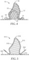
- FIG. 4 is a cross-sectional view of the dental article 10 of FIG. 1 after placement over a dental structure 26.
- the dental structure 26 is a prepared tooth.
- the prepared tooth may be prepared by any suitable process, e.g., cutting, grinding, shaping, etching, priming, coating with a dental adhesive, etc.
- An appropriate shape and size of a dental article is selected and provided.
- the dental article is then placed onto the prepared tooth, such that the prepared tooth is received in the volume of the shell (as seen in Fig. 4 ), whereby a portion of the hardenable dental composition 18' is displaced from the volume of the shell.
- the hardenable dental composition is not in contact with the dental structure during the placing step, after the placing step, or both during and after the placing step. In some of such embodiments, it may be desirable that the hardenable dental composition is displaced without contacting living dental tissue (e.g., a prepared tooth and gingival tissue). If the hardenable dental composition is in contact with the dental structure or the living dental tissue during the placing step, after the placing step, or both during and after the placing step, the displaced hardenable dental composition may adhere to the dental structure or the living dental tissue and may be difficult to be removed from the dental article. In some of such embodiments, a portion of the hardenable dental composition is displaced from the volume of the shell onto the isolation film to prevent the hardenable dental composition from being in contact with the dental structure or the living dental tissue.
- living dental tissue e.g., a prepared tooth and gingival tissue
- the dental article 110 of FIG. 2 can be placed over a dental structure, whereby a portion of the hardenable dental composition is displaced from the volume of the shell through a vent onto the outer surface of the shell.
- the hardenable dental composition is not in contact with the dental structure during the placing step, after the placing step, or both during and after the placing step.
- it may be also desirable that the hardenable dental composition is displaced without contacting living dental tissue (e.g., a prepared tooth and gingival tissue).
- the isolation film is radially stretched when the dental article is placed onto the dental structure.
- the hardenable dental composition is in contact with the isolation film during the placing step, after the placing step, or both during and after the placing step.
- the displaced hardenable dental composition can be removed (if desired) by any suitable instrument, e.g., a dental explorer.
- the article is then at least partially hardened (e.g., cured) by exposing it to heat/radiation to cause activation of the initiator system.
- the hardenable dental composition is at least partially cured inside the oral cavity of a patient, i.e., when the dental article is seated in place onto the dental structure.
- the isolation film and the shell can remain in contact with at least a portion of the hardenable dental composition during the curing step.
- a potential advantage of hardening the hardenable dental composition while the isolation film and the shell are still in contact with the portion of the hardenable dental composition is that exposure of the hardenable dental composition to oxygen during the hardening process may be reduced or prevented because of the protection provided by the shell and isolation film. Exposure of some hardenable dental compositions to oxygen during hardening may not be desired.
- the dental composition is hardened between the shell and the isolation film, the cured dental composition may be free of customary smear originating from oxygen inhibition layer used to protect the hardenable dental compositions from oxygen exposure. Hence, the surface of the cured dental composition may not require substantial polishing.
- the isolation film retained in place during curing may prevent the unnecessary adhesion and/or bonding of the cured dental composition to the dental structure (as a result of the intimate contact between the hardenable dental composition and the dental structure).
- the isolation film can, for example, provide a barrier against saliva, blood, and other fluid from being in contact with the hardenable dental composition and/or the dental structure during the restoration.
- the hardenable dental composition can then be cured, typically by exposing it to a dental curing light for a few seconds, if desired, while in the oral cavity, and then removing it carefully from the oral cavity and exposing it for final cure.
- the partially cured may be placed in a light curing chamber, optionally in combination with heat, to effect a complete cure.
- the dental article can be removed from the dental structure and the isolation film and/or the shell can also be removed from the dental article.
- the isolation film can be removed in a single piece. Removing the isolation film can, for example, provide an appropriate gap/clearance for cementing the hardened dental compositions.
- the hardened dental compositions i.e., in a shape of a crown
- the hardened dental compositions can be further modified in shape/finished by contouring, grinding, trimming, etc., if desired.
- the finished crown can be polished, cleaned, painted, or surface treated, if required for the intended application.
- the intended application may require mounting, bonding, or otherwise attaching the custom shaped cured crown to a second object adhesively, mechanically, or by combination of both.
- the finished crown can then be cemented as is or lined with a suitable resin composition prior to placement in the mouth.
- the shell may include at least one or more areas of weakness formed in the shell to facilitate the separation of the shell.
- the areas of weakness may define lines along which the shell can separate when tension is applied across the areas of weakness.
- the areas of weakness may take a variety of forms, e.g., thinned lines in which the wall thickness of the shell is reduced relative to the surrounding wall thickness, score lines, lines of perforations, etc.
- the areas of weakness may be defined by a filament molded in the shell such that the shell preferentially separates along the filament. Other variations providing a means of separation may be envisioned by those skilled in the art.
- FIG. 5 another embodiment of the dental article 510 in the shape of a crown is illustrated in a cross-sectional view.
- the dental article 510 includes a shell 512 defining volume, along with a circumferential base 514 and an incisal/occlusal region 516 similar to those discussed above.
- the volume of the shell 512 may contain hardenable dental composition 518 and an isolation film 520 is located at the circumferential base 514.
- the circumferential base 514 may include an optional flange 522.
- the flange 522 may be used to both facilitate manipulation of the dental article during placement on a prepared tooth and to provide a location at which the shell may be gripped to apply the force required to separate the one or more lines of weakness in the shell.
- flanges 522 may alternatively be located at a position removed from the base 514. In some other embodiments, flanges 522 are present for ease of removing shell 512 from dental article 510 at an appropriate time. In some embodiments, flanges 522 can extend in the facial/buccal direction, in the lingual direction, or in both the facial/buccal and lingual directions. In these some embodiments, flanges 522 do not interfere or contact with a neighboring tooth or teeth.
- dental articles including: (i) a tooth-shaped polymeric shell; (ii) a hardenable dental composition disposed within the polymeric shell; and (iii) an isolation film were assembled and evaluated.
- the dental articles were evaluated for ease of use and suitability in crown restorations, and in particular, "cure-in-place" full crown restorations where the hardenable dental composition was cured while the article was in place on a tooth preparation.
- the inventive dental article could be placed on a prepared tooth (natural, living, artificial, etc.), such that the isolation film was disposed between the prepared tooth surface and the hardenable dental composition.
- the article included an isolation film which was bonded to the circumferential gingival base of the shell, the film being sized to match that the gingival opening (i.e., the film was not oversized and was sealed at the gingival opening of the shell).
- the shell was non-continuous, and included one or more ports or openings to accommodate displacement of the hardenable dental composition during placement of the dental article onto the tooth preparation (such that the hardenable dental flowed from the shell interior onto the exterior of the shell).
- the isolation film stretched (and/or slid) during placement without tearing or perforating, and provided a barrier between the hardenable dental composition and the tooth preparation such that the uncured composition was not in contact with the prepared tooth, surrounding tissues (e.g., gingiva or neighboring teeth), or fluids (e.g., blood or saliva).
- the hardenable dental composition was then cured while the dental article was in place on the tooth preparation (e.g., with blue light, through the shell). If needed, the article was held in place (e.g., with the aid of finger pressure) before and/or during curing.
- the article was gently removed from the tooth preparation, and the shell and isolation film removed from the cured, crown-shaped, dental composition.
- the cured crown was cemented into place on the tooth preparation using a cement such as RelyX Luting Plus (a resin-modified glass ionomer cement) or RelyX Unicem (an adhesive resin cement), each available from 3M ESPE (St. Paul, MN).
- the film can also aid in the removal of the article from the tooth preparation after curing and/or provide an appropriately sized gap in the cured crown to accommodate cement.
- a similar dental article lacking an isolation film suffers from a number of undesirable drawbacks, including: discoloration of the restoration, partial adhesion and/or bonding of the cured dental composition to the tooth preparation (as a result of the intimate contact between the hardenable dental composition and the tooth preparation); mechanical interlocking of the cured dental composition to the tooth preparation (particularly if the hardenable dental composition is subject to shrinkage during curing); and insufficient space between the tooth preparation and the interior of the cured crown to accommodate an appropriate amount of cement while still being able to fully seat the crown.
- Tooth-shaped polymeric shells were prepared via a vacuum forming or via 3D-printing.
- shells were prepared using a Patterson vacuum forming unit (Item#090-9879, Patterson Dental Co., St. Paul, MN) with various thermoplastic sheet materials to form shells around standard, commercially available, stainless steel crowns (3M ESPE, St. Paul, MN).
- M ESPE standard, commercially available, stainless steel crowns
- the tooth-shaped polymeric shells were separated from the thermoplastic sheet with the stainless steel crowns still in place (i.e., within the shell), using the gingival portion of the stainless steel crowns as cutting guides to fully separate the shells from the sheet.
- Stainless steel crowns were then removed from the pliable shells.
- tooth-shaped polymeric shells of a predetermined thickness were manufactured using a Objet EDEN 500V PolyJet and UV-cured VeroWhite resin (Stratasys, Eden Prairie, MN) on the basis of digital data obtained from standard, commercially available, stainless steel crowns. Testing and evaluation of the dental articles were generally performed on shells sized for the restoration a primary lower left second molar or a primary upper right first molar However, it is understood that tooth-shapes shells could be readily manufactured for both anterior and posterior teeth (either permanent or primary), and in multiple sizes for any particular tooth.
- tooth-shaped polymeric shell examples generally: possessed continuous construction and relatively constant thickness (i.e., lacked holes or perforations on occlusal/incisal, buccal/labial, lingual, mesial, or distal surfaces); possessed an open base at the gingival portion through which to receive the tooth preparation (along with a portion the isolation film during placement); were transparent to actinic radiation; and were non-reactive to hardenable dental compositions, isolation films, and other dental article components.
- Shells of varying thickness could be produced from a variety of polymeric materials (polyesters, polycarbonates, acrylates, polymer blends, etc.).
- shell thicknesses generally corresponded to the thicknesses of the thermoplastic sheets employed.
- the shell material is not critical. However, it is desirable that the shells display sufficient strength such that they retain their shapes and do not permanently deform or collapse (whether filled or unfilled with the hardenable dental composition) during routine handling in a dental office.
- the shell be is thin as possible such that the interproximal gap(s) between the crown restoration and immediately adjacent teeth is minimized.
- the shell must not be so thin such that shell would rupture during placement of the dental article (i.e., as a result of the increased forces experienced by the shell during seating on the tooth preparation).
- S1-S4 Shell Shell Description S1 Clear/colorless vacuum-formed shell prepared from a clear polymer sheet (60% cellulose acetate and 40% diethyl phthalate), 0.5 mm in thickness x 127 mm width x 127 mm length Clear Splint Material, (available from Buffalo Dental Mfg Co., Syosette, NY) S2 Clear/colorless vacuum-formed shell prepared from a clear polycarbonate sheet, 0.25 mm in thickness (Makrofol HF312 G-4 020021, Bayer Material Sciences LLC, South Deerfield, MA) S3 Clear/colorless vacuum-formed shell prepared from a clear polycarbonate sheet, 0.375 mm in thickness (Makrofol HF312 G-4 020021, Bayer Material Sciences LLC, South Deerfield, MA) S4a Translucent 3D-printed shell, (0.15 mm thickness) prepared using VeroWhite acrylate-based resin (available from Stratasys Corp., Eden Prairie
- the dental articles included an isolation film, which in in vivo applications, would function to isolate the hardenable dental composition from saliva, blood, and other potential contaminants on, or adjacent to, the prepared tooth during and/or after placement of the article. Additionally, when the hardenable dental composition is cured while the article is in place on the tooth preparation, the isolation film which is disposed between the tooth preparation and the resultant cured dental composition (e.g., a crown) aids in the removal of the cured dental composition from the tooth preparation, since the cured dental composition is not in intimate contact with the surface of the tooth preparation. As noted above, the isolation film also provides a gap for which cement can be accommodated when the crown is finally cemented in place.
- the isolation film also provides a gap for which cement can be accommodated when the crown is finally cemented in place.
- the film properties may be used to control or influence the size of the cementation gap; the cementation gap may be predetermined.
- the isolation films were employed (0.015-0.12 mm). In all cases, the isolation films were compliant, stretchable, and tearresistant. Additionally, the isolation films did not adhere to the hardenable dental compositions (e.g., paste P1) after photocuring with blue light.
- Table 2 Isolation Films, F1-F5 Film, # Isolation Film Description
- F1 LDPE plastic wrap 0.015 mm in thickness (available from VWR, Chicago, IL)
- F2 Paraffin film 0.12 mm in thickness (available as ParaFilm "M” from American National Can, CT)
- F3 9715 Cotran 19% EVA film 0.075 mm in thickness x 89 mm wide (3M Health Care, Brookings, SD)
- F4 Nitrile sheet 0.1 mm thickness (available as KC500 nitrile glove from Kimberly-Clark, Roswell, GA)
- F5 Silicone coated 7-layer polyethylene/ethylene vinyl acetate copolymer film 0.05 mm thickness (available as Part# B429-BX261, Printpack, Atlanta GA)
- Hardenable dental compositions in the form of photocurable filled composite pastes were either obtained from commercial suppliers (i.e., pastes P1-P4, Table 3) or were experimentally prepared (i.e., pastes P5-10, Table 4).
- pastes P1-P4, Table 3 were experimentally prepared (i.e., pastes P5-10, Table 4).
- 20-gram batches of each paste were prepared by combining the indicated components and mixing with a Speedmixer at 3300 rpm for three 1-minute cycles followed by 12-hr degassing in individual syringes at 25 °C.
- the experimentally prepared pastes included identical photocurable resin packages and differed by filler loading (increasing from P5 to P10).
- Table 4 Experimental Pastes P5-P10 Paste S/T Silica/ Zirconia Clusters Filler, wt.% S/T 20 nm Silica Filler, wt.% S/T Nanozirconia Filler, wt.% Total Filler Loading, wt.% Photocurable Resin*, wt.
- dental practitioners generally desire good handling properties in hardenable dental compositions, as it often translates to time savings and patient satisfaction.
- the hardenable dental composition i.e., the paste
- the hardenable dental composition flow from the shell during placement of the dental article when reasonable forces are applied, such that amount of force needed to place the article on the tooth preparation does not cause discomfort for the patient and/or the dental practitioner during the restoration procedure.
- the hardenable dental composition flow from the shell in a reasonable amount of time during placement of the dental article (it is typically desired that the rheological properties of the hardenable dental composition are such that the dental article is capable of being fully placed (seated) on the tooth preparation in less than about 30 seconds, and more preferably less than about 10 seconds).
- the hardenable dental composition flow from the shell under a reasonable amount of applied force and in a reasonable amount of time, it is also desirable that the shell not permanently deform or rupture as a result of the forces experienced by the shell during placement of the article on the tooth to be restored.
- the hardenable dental composition not flow out of the shell under the force of gravity alone (e.g., during storage or handling), particularly when the hardenable dental composition is not sealed within shell.
- the yield stress of a particular material is the minimum stress required to cause that material to flow, and is described in " Rheology Principles, Measurements, and Applications” by C. W. Macosko, VCH Publishers, Inc., New York, 1994, p. 92 . If the stress due to gravity is below the yield stress of the material, then the material will not flow. The stress due to gravity, however, will depend on the mass of dental material being placed as well as the shape.
- the yield stresses of pastes P1-P10 were evaluated as follows. Approximately 0.15 g of a given paste was loaded between 8 mm diameter parallel plates in an AR-G2 rheometer (TA Instruments, New Castle, DE) and closed to a gap of ⁇ 1.0 mm. The parallel plates were lined with adhesive-backed sandpaper (9 ⁇ m in abrasive particle size) to minimize the paste from slipping at the plate surface during measurement. After scraping off excess paste, the sample was allowed to equilibrate at 37 °C, after which time an oscillatory stress sweep from 1.0 to 10 5 Pa was carried out at an angular frequency of 10 rad/s.
- paste P4 (a self-supporting malleable paste) displayed the highest yield stress.
- Experimental pastes P6-P10 displayed increasing yield stresses as a function of the total filler loading.
- the yield stress of the lightly filled experimental paste P5 was too low to accurately measure.
- Dental articles were assembled as follows. A given paste (P1-P10) was introduced through the circumferential opening at the gingival base of a given shell (S1-S4). The paste was added in a sufficient amount to fill the volume of the shell to 75% to 100%. Next, a piece of isolation film (F1-F5, approximately 25.4 mm x 25.4 mm), was centered over the base of the shell, such that the film covered the circumferential opening and extended beyond the base of shell in mesial, distal, buccal/labial, and lingual directions. The isolation film was maintained in place by adhesion of the film surface to the paste within the shell. The dental article was placed on a flat surface, film/gingival side down.
- the yield stress of the hardenable dental composition be sufficiently high as to prevent leaking from the shell, it is also desirable that the yield stress not be so high as to require substantial seating forces during placement of the article which could cause patient (or dental practitioner) pain or discomfort at typical procedure temperatures (i.e., room temperature to about 37 °C).
- the maximum compressive force required to seat the assembled dental article onto a shoulder prepared upper left first molar in a pediatric dentoform was measured in triplicate, both at 25 and 37 °C (each at 50% relative humidity).
- Dental articles tested included the same shell (S1) and isolation film (F1), but differed in pastes (P1, P3-P10) within the shell.
- Dental articles including the shell S1 and isolation film F3, but varying in experimental pastes, were evaluated by two dental practitioners (a prosthodontist and a pedodontist). The dental practitioners evaluated five dental articles per paste for ease of seating on a plastic tooth with shoulder preparation at room temperature, as well as for ease of cleaning of the displaced paste near the margin of the shell. Dental practitioner evaluations are summarized in Table 8 and are consistent with the data shown in Tables 6 and 7. In particular, CE5 containing a paste with relatively low yield stress was found to be too easy to seat on the tooth preparation, however the low viscosity "stringy" paste was difficult to clean up.
- Performance of the crowns obtained from the aforementioned dental articles was assessed by measuring the maximum tensile force required to separate the cemented crown from an artificial tooth.
- Plastic typodont teeth with the roots were used for the study. The tooth part of the typodonts were cut with either a chamfer or shoulder preparation.
- the prepared plastic teeth were replicated with Z250 dental composite (available from 3M ESPE, St Paul, MN) via a cast and cure approach.
- the individual composite (Z250) tooth-root structures with only the root portion were firmly cemented upright in molds of 2-part methacrylate composite (3-in dia. x 3-in high). Five each of composite teeth were cemented in the molds for the chamfer or for the shoulder preparations.
- each of the cemented composite tooth preparations was restored in the manner previously described, employing dental articles assembled from shell S1, paste P9, and film F5.
- the paste was cured by exposing the lingual, occlusal, and buccal surfaces of the shell with blue light for 10 seconds using an EPILAR S-10 curing light (3M ESPE, St. Paul, MN).
- the cement was dispensed into the crown inside cavity with an auto-mix delivery tip. Each crown with cement was placed on its corresponding tooth preparation with proper lingual-buccal alignment and was firmly pressed into place. After waiting 3 minutes, the excess cement around the crown margin was cleaned with a micro brush and the bonded crown / tooth preparation assembly was transferred into a humidity chamber (37 °C at 95% relative humidity) for 30-min for the cement to harden under self or dark cure mode. After the initial cement cure, the bonded samples were aged for an additional 24-hr at 37 °C under water prior to use in crown pull-off studies.
- Tensile pull-off force of a cemented crown to a Z250 composite tooth prep was measured with an Instron testing machine (Model#1123, available from Instron Inc., Norwood, MA) at 2-mm/min crosshead speed at 25 °C and 50% relative humidity.
- the cylindrical methacrylate composite base was held stationary in the Instron testing machine, while the upper crown was held by a mechanical vice grip attached to the moving crosshead.
- the maximum force required to separate the crown from the composite tooth model was recorded.
- Five measurements per tooth preparation per cement and their corresponding failure modes were recorded. As shown in Table-6, RelyX Unicem provided superior bonding of the crown to the Z250 tooth prep to break off the supporting root than cohesive failure of the cement.
- this example describes a dental article with a tooth-shaped shell with an optional vent located away from the circumferential base, a hardenable dental composition located within the shell, and an isolation film covering only the circumferential opening of the shell and is bonded to the circumferential base.
- Isolation film, F5 was bonded to the circumferential base of shell, S4, containing hardenable paste, P8, with cyanoacrylate glue (Scotch-Weld, 3M, St. Paul, MN).
- Dental explorer tip was used to create a vent, approximately 0.3 mm diameter, on the lingual occlusal cusp. Because the hardenable paste is sealed in a tooth-shaped shell, the described dental article can accommodate hardenable pastes of lower yield stress (such as P2, P5 and P6) without paste leaking out of the shell or ease of cleaning up the excess paste around circumferential margin.
- This version of dental article can be also be cured, finished, and cemented to tooth prep in the manner previously described.
- Example Dental Article Description Paste + Shell + Film Paste Retained in Shell? Perceived Seating Force Observations EX13 P8 + S4b + F4 Yes Moderate Acceptable
Claims (12)
- Procédé de durcissement d'un article dentaire durcissable (10, 110, 510), l'article dentaire durcissable (10, 110, 510) comprenant :une coque (12, 112, 512) définissant un volume, la coque comprenant une base circonférentielle (14, 114, 514) et une région incisive/occlusale (16, 116, 516) distale par rapport à la base circonférentielle ;une composition dentaire durcissable (18, 118, 518) située à l'intérieur du volume, dans laquelle la composition dentaire durcissable présente une limite apparente d'élasticité de 50 Pa à 4 000 Pa à 37 °C ; etun film d'isolation (20, 120, 520) situé au niveau de la base circonférentielle (14, 114, 514) de la coque (12, 112, 512), dans lequel le film d'isolation (20, 120, 520) est lié à la base circonférentielle (14, 114, 514) ;caractérisé en ce que le procédé comprend :la mise en place de l'article dentaire durcissable (10, 110, 510) sur une structure dentaire ; etensuite le durcissement de la composition dentaire durcissable (18, 118, 518), dans lequel le film d'isolation (20, 120, 520) reste en contact avec au moins une partie de la composition dentaire durcissable (18, 118, 518) pendant le durcissement, fournissant ainsi un espace entre l'article dentaire durci et la structure dentaire ;dans lequel la structure dentaire est une dent préparée ;dans lequel l'article dentaire durcissable est une couronne.
- Procédé selon la revendication 1, dans lequel la coque (12, 112, 512) a une forme de couronne.
- Procédé selon la revendication 1 ou 2, dans lequel la coque (12, 112, 512) a une épaisseur non supérieure à 1 mm.
- Procédé selon l'une quelconque des revendications 1 à 3, dans lequel la base circonférentielle (14, 114, 514) comporte au moins une bride (522) s'étendant dans la direction faciale/buccale, dans la direction linguale, ou à la fois dans les directions faciale/buccale et linguale.
- Procédé selon l'une quelconque des revendications 1 à 4, dans lequel le film d'isolation (20, 120, 520) est extensible radialement d'au moins 100 pour cent sans provoquer de perforation dans le film d'isolation.
- Procédé selon l'une quelconque des revendications 1 à 5, dans lequel la composition dentaire durcissable (18, 118, 518) est en contact avec le film d'isolation (20, 120, 520).
- Procédé selon l'une quelconque des revendications 1 à 6, dans lequel l'article dentaire est conçu pour recevoir une dent préparée dans une cavité buccale d'un patient et dans lequel la composition dentaire durcissable (18, 118, 518) n'entre pas en contact avec la dent préparée.
- Procédé selon l'une quelconque des revendications 1 à 7, dans lequel la base circonférentielle (14, 114, 514) comprend un diamètre maximal et le film d'isolation (20, 120, 520) s'étend au-delà de la base circonférentielle d'au moins 50 % du diamètre maximal.
- Procédé selon l'une quelconque des revendications 1 à 8, dans lequel la coque (12, 112, 512) est continue.
- Procédé selon l'une quelconque des revendications 1 à 9, dans lequel la coque (12, 112, 512) est discontinue.
- Procédé selon l'une quelconque des revendications 1 à 10, dans lequel la coque (12, 112, 512) comprend un évent (122).
- Procédé selon l'une quelconque des revendications 1 à 11, comprenant en outre un insert (19) situé à l'intérieur de la coque (12, 112, 512).
Applications Claiming Priority (2)
| Application Number | Priority Date | Filing Date | Title |
|---|---|---|---|
| US201462063454P | 2014-10-14 | 2014-10-14 | |
| PCT/US2015/053143 WO2016060845A1 (fr) | 2014-10-14 | 2015-09-30 | Articles à usage dentaire et leurs procédés d'utilisation |
Publications (2)
| Publication Number | Publication Date |
|---|---|
| EP3206624A1 EP3206624A1 (fr) | 2017-08-23 |
| EP3206624B1 true EP3206624B1 (fr) | 2023-08-30 |
Family
ID=54291711
Family Applications (1)
| Application Number | Title | Priority Date | Filing Date |
|---|---|---|---|
| EP15778547.8A Active EP3206624B1 (fr) | 2014-10-14 | 2015-09-30 | Méthodes de durcissement d'articles dentaires |
Country Status (3)
| Country | Link |
|---|---|
| US (1) | US10653501B2 (fr) |
| EP (1) | EP3206624B1 (fr) |
| WO (1) | WO2016060845A1 (fr) |
Families Citing this family (3)
| Publication number | Priority date | Publication date | Assignee | Title |
|---|---|---|---|---|
| US10751147B2 (en) * | 2015-03-26 | 2020-08-25 | 3M Innovative Properties Company | Methods of using hardenable dental articles |
| CN111973293B (zh) * | 2020-07-24 | 2021-09-14 | 上海交通大学医学院附属第九人民医院 | 一种铸瓷牙贴面制作方法 |
| EP4304518A1 (fr) * | 2021-03-10 | 2024-01-17 | 3M Innovative Properties Company | Restauration dentaire et son procédé de formation |
Family Cites Families (32)
| Publication number | Priority date | Publication date | Assignee | Title |
|---|---|---|---|---|
| US3460252A (en) | 1967-05-02 | 1969-08-12 | Miracle Dental Products Inc | Article and method for forming a denture |
| US3565387A (en) | 1968-09-17 | 1971-02-23 | Dental Innovations Inc | Prefabricated dental pattern having adjusting slot means |
| US3585723A (en) | 1969-06-20 | 1971-06-22 | Ion Co The | Dental crown and method of installation thereof |
| US3949476A (en) | 1974-03-25 | 1976-04-13 | Henry Kahn | Device useful in dental crown procedures and method of using the same |
| US4129946A (en) | 1977-02-17 | 1978-12-19 | Unitek Corporation | Dental crown form |
| CA1323949C (fr) | 1987-04-02 | 1993-11-02 | Michael C. Palazzotto | Systeme ternaire de photoinitiateur pour la polymerisation additive |
| US5348154A (en) | 1989-05-10 | 1994-09-20 | Minnesota Mining And Manufacturing Company | Packaging curable materials |
| US5100320A (en) | 1990-01-16 | 1992-03-31 | Minnesota Mining And Manufacturing Company | Dental packaging material and cartridge |
| US5192207A (en) | 1991-09-17 | 1993-03-09 | Rosellini Davey G | Composite resin crown, replacement tooth and method |
| US5487663A (en) | 1993-08-16 | 1996-01-30 | Wilson; George M. | Oral appliances and method |
| US5538129A (en) | 1995-03-21 | 1996-07-23 | Minnesota Mining And Manufacturing Company | Package for adhesive precoated dental appliance |
| US5552177A (en) | 1995-03-21 | 1996-09-03 | Minnesota Mining And Manufacturing Company | Method for applying adhesive to the base of an orthodontic appliance |
| US5785178A (en) | 1996-11-04 | 1998-07-28 | Minnesota Mining And Manufacturing Co. | Packaged photocurable composition |
| DE19736471A1 (de) | 1997-08-21 | 1999-02-25 | Espe Dental Ag | Lichtinduziert kationisch härtende Zusammensetzungen und deren Verwendung |
| US6187836B1 (en) | 1998-06-05 | 2001-02-13 | 3M Innovative Properties Company | Compositions featuring cationically active and free radically active functional groups, and methods for polymerizing such compositions |
| US6030606A (en) | 1998-06-22 | 2000-02-29 | 3M Innovative Properties Company | Dental restoratives comprising Bis-EMA6 |
| US5951294A (en) | 1998-09-09 | 1999-09-14 | Pierson; Kenneth W. | Method of creating an interim crown |
| US6572693B1 (en) | 1999-10-28 | 2003-06-03 | 3M Innovative Properties Company | Aesthetic dental materials |
| US6730156B1 (en) | 1999-10-28 | 2004-05-04 | 3M Innovative Properties Company | Clustered particle dental fillers |
| WO2001030307A1 (fr) | 1999-10-28 | 2001-05-03 | 3M Innovative Properties Company | Materiaux dentaires constitues de nano-particules de silice |
| US7134875B2 (en) * | 2002-06-28 | 2006-11-14 | 3M Innovative Properties Company | Processes for forming dental materials and device |
| US20050042577A1 (en) | 2003-08-19 | 2005-02-24 | Kvitrud James R. | Dental crown forms and methods |
| US20050040551A1 (en) | 2003-08-19 | 2005-02-24 | Biegler Robert M. | Hardenable dental article and method of manufacturing the same |
| US20050042576A1 (en) | 2003-08-19 | 2005-02-24 | Oxman Joel D. | Dental article forms and methods |
| US7649029B2 (en) | 2004-05-17 | 2010-01-19 | 3M Innovative Properties Company | Dental compositions containing nanozirconia fillers |
| US7321004B2 (en) * | 2005-02-11 | 2008-01-22 | New Photonics, Llc | Method for photo-curing polymerizable compositions |
| JP5399069B2 (ja) | 2005-08-10 | 2014-01-29 | デンツプライ インターナショナル インコーポレーテッド | チェアサイド歯科用クラウンを製造する方法 |
| EP2077795A1 (fr) * | 2006-09-13 | 2009-07-15 | 3M Innovative Properties Company | Articles dentaires multicouche malléable préformés |
| JP2010021204A (ja) * | 2008-07-08 | 2010-01-28 | Toshiba Corp | 半導体装置及びその製造方法 |
| US8979536B2 (en) * | 2008-11-17 | 2015-03-17 | 3M Innovative Properties Company | Preformed malleable dental articles and methods |
| US20100203480A1 (en) | 2009-02-06 | 2010-08-12 | Dean Schweitzer | Dental crown shell and method of use |
| US20110117524A1 (en) | 2009-11-16 | 2011-05-19 | Tri-Dent Innovations Limited | Universal dental crown and system and method of restoring a tooth using a universal dental crown |
-
2015
- 2015-09-30 WO PCT/US2015/053143 patent/WO2016060845A1/fr active Application Filing
- 2015-09-30 EP EP15778547.8A patent/EP3206624B1/fr active Active
- 2015-09-30 US US15/519,063 patent/US10653501B2/en active Active
Also Published As
| Publication number | Publication date |
|---|---|
| US10653501B2 (en) | 2020-05-19 |
| WO2016060845A1 (fr) | 2016-04-21 |
| US20170224440A1 (en) | 2017-08-10 |
| EP3206624A1 (fr) | 2017-08-23 |
Similar Documents
| Publication | Publication Date | Title |
|---|---|---|
| US8308478B2 (en) | Methods for indirect bonding of orthodontic appliances | |
| Hahn et al. | Influence of resin cement viscosity on microleakage of ceramic inlays | |
| EP2227195B1 (fr) | Procédés et kits pour la fabrication de protections dentaires flexibles | |
| US20100021868A1 (en) | Dental crown forms and methods | |
| US20100062394A1 (en) | Preformed malleable multilayer dental articles | |
| Aggarwal et al. | Effect of cyclic loading on marginal adaptation and bond strength in direct vs indirect class II MO composite restorations | |
| WO2011156806A1 (fr) | Stents et méthode de restauration dentaire les utilisant | |
| JP2011041827A (ja) | 歯科矯正器具のインダイレクトボンディング用の装置およびその作製方法 | |
| Al-Saleh et al. | Microleakage of posterior composite restorations lined with self-adhesive resin cements | |
| EP3206624B1 (fr) | Méthodes de durcissement d'articles dentaires | |
| de Andrade et al. | Ultimate Ceramic Veneers: A Laboratory-Guided Ultraconservative Preparation Concept for Maximum Enamel Preservation. | |
| Bhoyar | Esthetic closure of diastema by porcelain laminate veneers: a case report | |
| Watanabe et al. | Restoration of a microdont using the resin composite injection technique with a fully digital workflow: a flexible 3D-printed index with a stabilization holder | |
| Özcan et al. | Effect of ultrasonic versus manual cementation on the fracture strength of resin composite laminates | |
| Görücü | Fracture resistance of class II preformed ceramic insert and direct composite resin restorations | |
| Heymann et al. | Introduction to composite restorations | |
| Gresnigt et al. | Partial anterior indirect restorations in cases with dentin exposure | |
| Pranati et al. | Marginal Adaptability of custom-made Cast Post Made by Different Techniques-A Literature Review | |
| Villalobos-Tinoco et al. | Injectable Flowable Resin-based Composite Veneers Prior to Ceramic Veneers | |
| Field et al. | Provisional restorations | |
| WO2017034017A1 (fr) | Plaque dentale de référence, prothèse dentaire de référence, trousse de fabrication de prothèse dentaire et procédé de fabrication de prothèse dentaire | |
| Schäffer et al. | Complete restoration with resin-bonded porcelain inlays. | |
| Küçük et al. | Clinical Applications of Soft Lining Materials | |
| Bandéca et al. | Indirect resin onlay cemented with selfadhesive resin cement: a comprehensive clinical overview | |
| Johnson | Restorative Dentistry Clinical Reference® |
Legal Events
| Date | Code | Title | Description |
|---|---|---|---|
| STAA | Information on the status of an ep patent application or granted ep patent |
Free format text: STATUS: THE INTERNATIONAL PUBLICATION HAS BEEN MADE |
|
| PUAI | Public reference made under article 153(3) epc to a published international application that has entered the european phase |
Free format text: ORIGINAL CODE: 0009012 |
|
| STAA | Information on the status of an ep patent application or granted ep patent |
Free format text: STATUS: REQUEST FOR EXAMINATION WAS MADE |
|
| 17P | Request for examination filed |
Effective date: 20170418 |
|
| AK | Designated contracting states |
Kind code of ref document: A1 Designated state(s): AL AT BE BG CH CY CZ DE DK EE ES FI FR GB GR HR HU IE IS IT LI LT LU LV MC MK MT NL NO PL PT RO RS SE SI SK SM TR |
|
| AX | Request for extension of the european patent |
Extension state: BA ME |
|
| DAV | Request for validation of the european patent (deleted) | ||
| DAX | Request for extension of the european patent (deleted) | ||
| STAA | Information on the status of an ep patent application or granted ep patent |
Free format text: STATUS: EXAMINATION IS IN PROGRESS |
|
| 17Q | First examination report despatched |
Effective date: 20180518 |
|
| STAA | Information on the status of an ep patent application or granted ep patent |
Free format text: STATUS: EXAMINATION IS IN PROGRESS |
|
| GRAP | Despatch of communication of intention to grant a patent |
Free format text: ORIGINAL CODE: EPIDOSNIGR1 |
|
| STAA | Information on the status of an ep patent application or granted ep patent |
Free format text: STATUS: GRANT OF PATENT IS INTENDED |
|
| INTG | Intention to grant announced |
Effective date: 20230313 |
|
| GRAS | Grant fee paid |
Free format text: ORIGINAL CODE: EPIDOSNIGR3 |
|
| GRAA | (expected) grant |
Free format text: ORIGINAL CODE: 0009210 |
|
| STAA | Information on the status of an ep patent application or granted ep patent |
Free format text: STATUS: THE PATENT HAS BEEN GRANTED |
|
| AK | Designated contracting states |
Kind code of ref document: B1 Designated state(s): AL AT BE BG CH CY CZ DE DK EE ES FI FR GB GR HR HU IE IS IT LI LT LU LV MC MK MT NL NO PL PT RO RS SE SI SK SM TR |
|
| P01 | Opt-out of the competence of the unified patent court (upc) registered |
Effective date: 20230721 |
|
| REG | Reference to a national code |
Ref country code: GB Ref legal event code: FG4D |
|
| REG | Reference to a national code |
Ref country code: CH Ref legal event code: EP |
|
| REG | Reference to a national code |
Ref country code: DE Ref legal event code: R096 Ref document number: 602015085406 Country of ref document: DE |
|
| REG | Reference to a national code |
Ref country code: IE Ref legal event code: FG4D |
|
| PGFP | Annual fee paid to national office [announced via postgrant information from national office to epo] |
Ref country code: DE Payment date: 20230822 Year of fee payment: 9 |
|
| REG | Reference to a national code |
Ref country code: LT Ref legal event code: MG9D |
|
| REG | Reference to a national code |
Ref country code: NL Ref legal event code: MP Effective date: 20230830 |
|
| REG | Reference to a national code |
Ref country code: AT Ref legal event code: MK05 Ref document number: 1604419 Country of ref document: AT Kind code of ref document: T Effective date: 20230830 |
|
| PG25 | Lapsed in a contracting state [announced via postgrant information from national office to epo] |
Ref country code: GR Free format text: LAPSE BECAUSE OF FAILURE TO SUBMIT A TRANSLATION OF THE DESCRIPTION OR TO PAY THE FEE WITHIN THE PRESCRIBED TIME-LIMIT Effective date: 20231201 |
|
| PG25 | Lapsed in a contracting state [announced via postgrant information from national office to epo] |
Ref country code: IS Free format text: LAPSE BECAUSE OF FAILURE TO SUBMIT A TRANSLATION OF THE DESCRIPTION OR TO PAY THE FEE WITHIN THE PRESCRIBED TIME-LIMIT Effective date: 20231230 |
|
| PG25 | Lapsed in a contracting state [announced via postgrant information from national office to epo] |
Ref country code: SE Free format text: LAPSE BECAUSE OF FAILURE TO SUBMIT A TRANSLATION OF THE DESCRIPTION OR TO PAY THE FEE WITHIN THE PRESCRIBED TIME-LIMIT Effective date: 20230830 Ref country code: RS Free format text: LAPSE BECAUSE OF FAILURE TO SUBMIT A TRANSLATION OF THE DESCRIPTION OR TO PAY THE FEE WITHIN THE PRESCRIBED TIME-LIMIT Effective date: 20230830 Ref country code: NO Free format text: LAPSE BECAUSE OF FAILURE TO SUBMIT A TRANSLATION OF THE DESCRIPTION OR TO PAY THE FEE WITHIN THE PRESCRIBED TIME-LIMIT Effective date: 20231130 Ref country code: LV Free format text: LAPSE BECAUSE OF FAILURE TO SUBMIT A TRANSLATION OF THE DESCRIPTION OR TO PAY THE FEE WITHIN THE PRESCRIBED TIME-LIMIT Effective date: 20230830 Ref country code: LT Free format text: LAPSE BECAUSE OF FAILURE TO SUBMIT A TRANSLATION OF THE DESCRIPTION OR TO PAY THE FEE WITHIN THE PRESCRIBED TIME-LIMIT Effective date: 20230830 Ref country code: IS Free format text: LAPSE BECAUSE OF FAILURE TO SUBMIT A TRANSLATION OF THE DESCRIPTION OR TO PAY THE FEE WITHIN THE PRESCRIBED TIME-LIMIT Effective date: 20231230 Ref country code: HR Free format text: LAPSE BECAUSE OF FAILURE TO SUBMIT A TRANSLATION OF THE DESCRIPTION OR TO PAY THE FEE WITHIN THE PRESCRIBED TIME-LIMIT Effective date: 20230830 Ref country code: GR Free format text: LAPSE BECAUSE OF FAILURE TO SUBMIT A TRANSLATION OF THE DESCRIPTION OR TO PAY THE FEE WITHIN THE PRESCRIBED TIME-LIMIT Effective date: 20231201 Ref country code: FI Free format text: LAPSE BECAUSE OF FAILURE TO SUBMIT A TRANSLATION OF THE DESCRIPTION OR TO PAY THE FEE WITHIN THE PRESCRIBED TIME-LIMIT Effective date: 20230830 Ref country code: AT Free format text: LAPSE BECAUSE OF FAILURE TO SUBMIT A TRANSLATION OF THE DESCRIPTION OR TO PAY THE FEE WITHIN THE PRESCRIBED TIME-LIMIT Effective date: 20230830 |
|
| PG25 | Lapsed in a contracting state [announced via postgrant information from national office to epo] |
Ref country code: PL Free format text: LAPSE BECAUSE OF FAILURE TO SUBMIT A TRANSLATION OF THE DESCRIPTION OR TO PAY THE FEE WITHIN THE PRESCRIBED TIME-LIMIT Effective date: 20230830 Ref country code: NL Free format text: LAPSE BECAUSE OF FAILURE TO SUBMIT A TRANSLATION OF THE DESCRIPTION OR TO PAY THE FEE WITHIN THE PRESCRIBED TIME-LIMIT Effective date: 20230830 |
|
| RAP2 | Party data changed (patent owner data changed or rights of a patent transferred) |
Owner name: SOLVENTUM INTELLECTUAL PROPERTIES COMPANY |
|
| REG | Reference to a national code |
Ref country code: DE Ref legal event code: R081 Ref document number: 602015085406 Country of ref document: DE Owner name: SOLVENTUM INTELLECTUAL PROPERTIES CO. (N.D.GES, US Free format text: FORMER OWNER: 3M INNOVATIVE PROPERTIES COMPANY, ST. PAUL, MN, US |