EP3206590B1 - Catheter comprising a cutting element - Google Patents
Catheter comprising a cutting element Download PDFInfo
- Publication number
- EP3206590B1 EP3206590B1 EP15804238.2A EP15804238A EP3206590B1 EP 3206590 B1 EP3206590 B1 EP 3206590B1 EP 15804238 A EP15804238 A EP 15804238A EP 3206590 B1 EP3206590 B1 EP 3206590B1
- Authority
- EP
- European Patent Office
- Prior art keywords
- cutting element
- tube
- catheter
- catheter according
- sleeve
- Prior art date
- Legal status (The legal status is an assumption and is not a legal conclusion. Google has not performed a legal analysis and makes no representation as to the accuracy of the status listed.)
- Active
Links
- 238000003780 insertion Methods 0.000 claims description 38
- 230000037431 insertion Effects 0.000 claims description 38
- 210000004204 blood vessel Anatomy 0.000 claims description 6
- 239000012530 fluid Substances 0.000 claims description 4
- 230000001154 acute effect Effects 0.000 claims description 3
- 238000000034 method Methods 0.000 description 15
- 239000003550 marker Substances 0.000 description 9
- 210000003462 vein Anatomy 0.000 description 8
- 230000007794 irritation Effects 0.000 description 7
- 239000000126 substance Substances 0.000 description 7
- 230000008602 contraction Effects 0.000 description 4
- 210000003205 muscle Anatomy 0.000 description 4
- 206010046996 Varicose vein Diseases 0.000 description 3
- 238000002679 ablation Methods 0.000 description 3
- 210000004369 blood Anatomy 0.000 description 3
- 239000008280 blood Substances 0.000 description 3
- 230000000694 effects Effects 0.000 description 3
- 210000003038 endothelium Anatomy 0.000 description 3
- 210000003141 lower extremity Anatomy 0.000 description 3
- 208000027185 varicose disease Diseases 0.000 description 3
- 201000002282 venous insufficiency Diseases 0.000 description 3
- 239000013543 active substance Substances 0.000 description 2
- 230000015572 biosynthetic process Effects 0.000 description 2
- 230000017531 blood circulation Effects 0.000 description 2
- 239000003795 chemical substances by application Substances 0.000 description 2
- 238000010276 construction Methods 0.000 description 2
- 208000037265 diseases, disorders, signs and symptoms Diseases 0.000 description 2
- 239000006260 foam Substances 0.000 description 2
- 239000002184 metal Substances 0.000 description 2
- 238000002604 ultrasonography Methods 0.000 description 2
- 230000002792 vascular Effects 0.000 description 2
- 206010065929 Cardiovascular insufficiency Diseases 0.000 description 1
- 201000004624 Dermatitis Diseases 0.000 description 1
- 206010061218 Inflammation Diseases 0.000 description 1
- 206010030113 Oedema Diseases 0.000 description 1
- 208000018262 Peripheral vascular disease Diseases 0.000 description 1
- FAPWRFPIFSIZLT-UHFFFAOYSA-M Sodium chloride Chemical compound [Na+].[Cl-] FAPWRFPIFSIZLT-UHFFFAOYSA-M 0.000 description 1
- 230000002159 abnormal effect Effects 0.000 description 1
- 210000000601 blood cell Anatomy 0.000 description 1
- 201000002816 chronic venous insufficiency Diseases 0.000 description 1
- 238000004581 coalescence Methods 0.000 description 1
- 230000001419 dependent effect Effects 0.000 description 1
- 201000010099 disease Diseases 0.000 description 1
- 208000035475 disorder Diseases 0.000 description 1
- 210000003414 extremity Anatomy 0.000 description 1
- 238000003384 imaging method Methods 0.000 description 1
- 230000004054 inflammatory process Effects 0.000 description 1
- 238000002347 injection Methods 0.000 description 1
- 239000007924 injection Substances 0.000 description 1
- 230000003902 lesion Effects 0.000 description 1
- 239000006193 liquid solution Substances 0.000 description 1
- 239000000463 material Substances 0.000 description 1
- 238000012148 non-surgical treatment Methods 0.000 description 1
- 238000013021 overheating Methods 0.000 description 1
- 239000008152 sclerosing solution Substances 0.000 description 1
- 206010040882 skin lesion Diseases 0.000 description 1
- 231100000444 skin lesion Toxicity 0.000 description 1
- 239000000243 solution Substances 0.000 description 1
- 208000009056 telangiectasis Diseases 0.000 description 1
- 210000001519 tissue Anatomy 0.000 description 1
- 210000002073 venous valve Anatomy 0.000 description 1
- 238000013022 venting Methods 0.000 description 1
Images


Classifications
-
- A—HUMAN NECESSITIES
- A61—MEDICAL OR VETERINARY SCIENCE; HYGIENE
- A61B—DIAGNOSIS; SURGERY; IDENTIFICATION
- A61B17/00—Surgical instruments, devices or methods, e.g. tourniquets
- A61B17/32—Surgical cutting instruments
- A61B17/3205—Excision instruments
- A61B17/3207—Atherectomy devices working by cutting or abrading; Similar devices specially adapted for non-vascular obstructions
- A61B17/320725—Atherectomy devices working by cutting or abrading; Similar devices specially adapted for non-vascular obstructions with radially expandable cutting or abrading elements
-
- A—HUMAN NECESSITIES
- A61—MEDICAL OR VETERINARY SCIENCE; HYGIENE
- A61B—DIAGNOSIS; SURGERY; IDENTIFICATION
- A61B17/00—Surgical instruments, devices or methods, e.g. tourniquets
- A61B17/00008—Vein tendon strippers
-
- A—HUMAN NECESSITIES
- A61—MEDICAL OR VETERINARY SCIENCE; HYGIENE
- A61B—DIAGNOSIS; SURGERY; IDENTIFICATION
- A61B17/00—Surgical instruments, devices or methods, e.g. tourniquets
- A61B17/12—Surgical instruments, devices or methods, e.g. tourniquets for ligaturing or otherwise compressing tubular parts of the body, e.g. blood vessels, umbilical cord
- A61B17/12022—Occluding by internal devices, e.g. balloons or releasable wires
- A61B17/12027—Type of occlusion
- A61B17/12031—Type of occlusion complete occlusion
-
- A—HUMAN NECESSITIES
- A61—MEDICAL OR VETERINARY SCIENCE; HYGIENE
- A61B—DIAGNOSIS; SURGERY; IDENTIFICATION
- A61B17/00—Surgical instruments, devices or methods, e.g. tourniquets
- A61B17/32—Surgical cutting instruments
- A61B17/3205—Excision instruments
- A61B17/3207—Atherectomy devices working by cutting or abrading; Similar devices specially adapted for non-vascular obstructions
-
- A—HUMAN NECESSITIES
- A61—MEDICAL OR VETERINARY SCIENCE; HYGIENE
- A61M—DEVICES FOR INTRODUCING MEDIA INTO, OR ONTO, THE BODY; DEVICES FOR TRANSDUCING BODY MEDIA OR FOR TAKING MEDIA FROM THE BODY; DEVICES FOR PRODUCING OR ENDING SLEEP OR STUPOR
- A61M25/00—Catheters; Hollow probes
- A61M25/0021—Catheters; Hollow probes characterised by the form of the tubing
- A61M25/0023—Catheters; Hollow probes characterised by the form of the tubing by the form of the lumen, e.g. cross-section, variable diameter
- A61M25/0026—Multi-lumen catheters with stationary elements
-
- A—HUMAN NECESSITIES
- A61—MEDICAL OR VETERINARY SCIENCE; HYGIENE
- A61B—DIAGNOSIS; SURGERY; IDENTIFICATION
- A61B17/00—Surgical instruments, devices or methods, e.g. tourniquets
- A61B17/12—Surgical instruments, devices or methods, e.g. tourniquets for ligaturing or otherwise compressing tubular parts of the body, e.g. blood vessels, umbilical cord
- A61B17/12022—Occluding by internal devices, e.g. balloons or releasable wires
- A61B17/12099—Occluding by internal devices, e.g. balloons or releasable wires characterised by the location of the occluder
- A61B17/12109—Occluding by internal devices, e.g. balloons or releasable wires characterised by the location of the occluder in a blood vessel
-
- A—HUMAN NECESSITIES
- A61—MEDICAL OR VETERINARY SCIENCE; HYGIENE
- A61B—DIAGNOSIS; SURGERY; IDENTIFICATION
- A61B17/00—Surgical instruments, devices or methods, e.g. tourniquets
- A61B17/12—Surgical instruments, devices or methods, e.g. tourniquets for ligaturing or otherwise compressing tubular parts of the body, e.g. blood vessels, umbilical cord
- A61B17/12022—Occluding by internal devices, e.g. balloons or releasable wires
- A61B17/12131—Occluding by internal devices, e.g. balloons or releasable wires characterised by the type of occluding device
- A61B17/12181—Occluding by internal devices, e.g. balloons or releasable wires characterised by the type of occluding device formed by fluidized, gelatinous or cellular remodelable materials, e.g. embolic liquids, foams or extracellular matrices
- A61B17/12186—Occluding by internal devices, e.g. balloons or releasable wires characterised by the type of occluding device formed by fluidized, gelatinous or cellular remodelable materials, e.g. embolic liquids, foams or extracellular matrices liquid materials adapted to be injected
-
- A—HUMAN NECESSITIES
- A61—MEDICAL OR VETERINARY SCIENCE; HYGIENE
- A61B—DIAGNOSIS; SURGERY; IDENTIFICATION
- A61B17/00—Surgical instruments, devices or methods, e.g. tourniquets
- A61B2017/00743—Type of operation; Specification of treatment sites
- A61B2017/00778—Operations on blood vessels
-
- A—HUMAN NECESSITIES
- A61—MEDICAL OR VETERINARY SCIENCE; HYGIENE
- A61B—DIAGNOSIS; SURGERY; IDENTIFICATION
- A61B17/00—Surgical instruments, devices or methods, e.g. tourniquets
- A61B17/22—Implements for squeezing-off ulcers or the like on the inside of inner organs of the body; Implements for scraping-out cavities of body organs, e.g. bones; Calculus removers; Calculus smashing apparatus; Apparatus for removing obstructions in blood vessels, not otherwise provided for
- A61B17/221—Gripping devices in the form of loops or baskets for gripping calculi or similar types of obstructions
- A61B2017/2215—Gripping devices in the form of loops or baskets for gripping calculi or similar types of obstructions having an open distal end
-
- A—HUMAN NECESSITIES
- A61—MEDICAL OR VETERINARY SCIENCE; HYGIENE
- A61B—DIAGNOSIS; SURGERY; IDENTIFICATION
- A61B17/00—Surgical instruments, devices or methods, e.g. tourniquets
- A61B17/32—Surgical cutting instruments
- A61B17/3205—Excision instruments
- A61B17/3207—Atherectomy devices working by cutting or abrading; Similar devices specially adapted for non-vascular obstructions
- A61B2017/320741—Atherectomy devices working by cutting or abrading; Similar devices specially adapted for non-vascular obstructions for stripping the intima or the internal plaque from a blood vessel, e.g. for endarterectomy
Definitions
- the object of the present invention is a catheter comprising a cutting element, i.e. an element that can controllably cut (damage) internal areas of walls of a blood vessel.
- the invention relates to the field of medical devices introduced percutaneously into a blood vessel in order to perform the procedure of its mechanical or chemical and mechanical obliteration (ablation, closure).
- Chronic venous insufficiency is a peripheral vascular disease observed in the half of the adult population and leads to the formation of varicose veins, so-called "spider veins", venous inflammations, oedemas.
- Circulatory insufficiency in the lower extremities is a disease whose incidence increases with age, which results in an increasing demand for less invasive, non-surgical treatments to eliminate problems such as varicose veins of the lower extremities.
- Venous stasis is a disorder caused by abnormal blood flow from the lower extremities to the heart. Contrary to appearances, not only the heart is responsible for ensuring the proper blood circulation in the organism. The work of the leg muscles (muscle pump) is responsible for returning blood to the heart. In a healthy body, muscles allow blood to return to the heart through the venous valve system. When lesions are observed, the "muscle pump" in the area of the extremities fails to work and / or the valve system does not sufficiently support the return of blood to the heart.
- venous insufficiency various veins
- Methods of treating venous insufficiency are limited.
- Currently used methods are based on stripping or ligation of insufficient venous sections, vein ablation using a laser or by the application of ultrasound, or steam, as well as through chemical obliteration by local injection of chemical substances that cause irritation to the inner walls of veins and, as a result, their coalescence (closing).
- WO 2004/112569 A2 discloses a vascular ablation apparatus that delivers a sclerosing solution during the disruption and/ or irritation of a vessel wall.
- the present invention solves many of the problems indicated above by providing a simple and effective mechanical catheter for closing veins.
- a catheter provided with technical means for mechanical irritation of the vessels is proposed.
- Such a device allows solving many of the problems signalled above.
- the developed catheter allows simultaneous support of mechanical obliteration by chemical obliteration, i.e. the catheter is provided with a channel for the administration of active substances.
- the proposed solution helps to minimise the size of the catheter, which allows it to operate in narrow, deformed, affected vessels.
- the assembly of the inner tube comprises the distal tube of a smaller diameter and the body tube of a greater diameter, forming the proximal portion of the assembly, wherein the cutting element is mounted on the distal tube.
- the sleeve has a diameter equal to the diameter of the body tube of the assembly of the inner tube and this sleeve, from its proximal side, is immediately adjacent to the body tube.
- the cutting element comprises 3 to 10 arms, which are preferably arc-shaped outward with respect to the axis of the catheter, and in the released state, in the vicinity of the sleeve, these arms are arranged at an acute angle in relation to the axis of the catheter.
- the sharp endings of the cutting element are bent away from the arms outwardly with respect to the axis of the catheter, and these endings are conically pointed or form an elongated blade.
- the catheter comprises a channel for fluid supply.
- the cutting element is made of a single tube segment.
- the insertion tube has an outer diameter of less than 2.2 mm.
- the degree of release and unfolding of the arms of the cutting element is adjusted with the position of the distal edge of the insertion tube in relation to this element.
- the cutting element has a shape adapted for repeated and multiple insertion of it entirely within the insertion tube, which in this position is in contact with the tip.
- Fig. 1 shows a general view of the catheter with the cutting element completely released from the insertion tube, with the detail "A" and the plane of the cross section B-B also marked
- Fig. 2 shows an enlarged detail "A” marked in Fig. 1 showing the point of connection of the body tube and the distal tube, as well as the place of mounting the sleeve of the cutting element
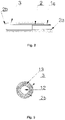
- Fig. 3 shows an enlarged B-B cross-sectional view of the catheter in the place marked on the Fig. 1
- Fig. 4 shows the catheter of Fig. 1 in the closed position, with the cutting element hidden under the insertion tube
- Fig. 5 shows the catheter of Fig.
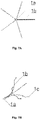
- FIG. 6A and 6B , 7A and 7B , and 8A and 8B show an enlarged structure of the cutting element with, respectively, three, five and ten arms, wherein Fig. 6A , 7A and 8A show a view of the cutting elements exploded (open) from the side of their sharp ends, and Fig. 6B , 7B and 8B show a general view of these cutting elements in an enlargement.
- the catheter according to the present invention comprises a springy resilient (elastic) cutting element that is mounted on the distal tube 2a of the assembly 2 of the inner tube, and comprises, successively, viewed from the proximal (the operator's) side, the sleeve 1a and the arc-curved longitudinal arms 1b with the properly formed and bent outwards sharpened endings 1c , connected thereto at its distal edge and facing towards the atraumatic tip 7.
- the arms 1b form a band of identical elements (branches of the cutting element protruding from the axis of the catheter). It is possible to profile the arms 1 b in any way in order to achieve the effect of irritation of the vessel wall by the sharp endings 1c.
- the assembly 2 of the inner tube consists of two concentrically arranged tubes, the distal tube 2a and the body tube 2b of a larger diameter, which is the proximal portion of the assembly 2 of the inner tube.
- the distal tube 2a is adapted in its diameter to the body tube 2b, so that it is possible to contiguously mount the tubes one in another at the point of their connection (shown in Fig. 2 ).
- the body tube 2b supports the tube 2a with a smaller diameter, located further, in the distal portion of the catheter.
- the sleeve 1a of the cutting element 1 has a diameter equal (or nearly equal) to the diameter of the body tube 2b.
- the described mutual arrangement of the tubes 2a and 2b and the sleeve 1a is shown in Fig.
- the insertion tube 3 with a diameter larger than the tube 2a and the sleeve 1a, covers both these elements, together with the arms 1b and the endings 1c of the cutting element, and therefore the cutting element 1 without obstacles can be repeatedly released and retracted by sliding it within the tube 3.
- the insertion tube 3 has preferably an outer diameter of less than 2.2 mm.
- the sleeve 1a is mounted on the distal tube 2a in such a manner that the proximal edge of the sleeve 1a is in direct contact with the distal edge of the body tube 2b.
- Number of the arms 1b of the cutting element is in the range of 3 to 10, e.g. the cutting element can comprise 3, 4, 5, 6 arms 1b.
- the arms 1b in relation to the axis of the sleeve 1a and the axis of the catheter are arranged symmetrically e.g. on the circumference of the sleeve at every 120° (3 arms) or every 90° (4 arms), etc., as shown demonstratively in Fig. 6A , 7A and 8A .
- the arms 1b have the form of branches extending from the sleeve 1a and can have a circular cross-section (particularly when formed from wires attached to the sleeve) or approximately trapezoidal cross-section (when formed by cutting out the arms and the sleeve from one section of metal tube).
- the arms 1b are formed so that when releasing the element 1 from the catheter they radially extend outward, away from the assembly 2 of the inner tube towards the walls of the blood vessel.
- the arms 1b after full extension of the cutting element (releasing it from the insertion tube 3 ) are arranged in a section adjacent to the sleeve at an acute angle in relation to the axis of the catheter, e.g. at an angle of 60° or 45°.
- the arms 1b of the end portion, remote from the sleeve 1a are profiled (bent) arcuately, so that the sharp endings 1c are adjacent to the walls of the vessel.
- the arms 1b can also be formed as a line similar to the letter "S", or in a yet different way, however, the endings 1c are always most remote from the axis of the catheter.
- the sharp endings 1c are bent away from the arms 1b outwardly with respect to the axis of the catheter, i.e. they are more strongly curved outwardly than the line of curvature of the arms 1b.
- the endings 1c can be conically pointed or can create slightly elongated blade by flattening the end sections of the arms 1b.
- the cutting element 1 can be completely cut out from the section of the tube of metal or other material and then the beginning of such a tube is not treated (the sleeve remains) and in the remaining portion of the tube cutting is carried out to obtain a desired number of arms, therefore 3 to 10 arms are cut in the tube. It is also possible to prepare the cutting element 1 by mounting previously prepared single arms 1b to the section of the tube (the sleeve). These arms are mounted to the sleeve in such manner that the diameter of the retracted cutting element 1 along its length does not exceed the diameter of the sleeve 1a, when the element 1 is retracted in the insertion tube 3.
- the catheter can have a minimum diameter limited only with the diameter of the sleeve 1a, increased by the addition of the insertion tube 3.
- the space is maintained constituting the channel 13 for fluid supply, for example of sclerotisation chemicals (including foams), pharmacologically active agents, saline solution, etc.
- the channel 12 for the guidewire was led, preferably for the guidewire of the dimension 0.89 mm (0.035").
- the guidewire provides stable positioning of the catheter during the procedure.
- the catheter In its proximal portion, the catheter comprises known in the art elements accessible for the operator, enabling control of the device. Subsequently, from the proximal side, the catheter is provided with the cap 5 of the assembly of the inner tube, from which the cuff 9 of the assembly of the inner tube is led, next the "Y" cap 6 and the cap 4 of the insertion tube. The cap 4 and the "Y" cap 6 are used together to control the insertion tube.
- the atraumatic soft tip 7 On the distal tube 2a, at its end, after the cutting element 1, there is mounted the atraumatic soft tip 7 enabling atraumatic insertion of the catheter into the vessel.
- the catheter can preferably comprise markers visible through ultrasound and / or X-ray imaging, enabling operation of the device during procedure.
- the marker 8 On the insertion tube 3, at its distal portion, there is provided the marker 8, and on the body tube 2b, at its proximal side, there is provided the first marker 10 followed by the second marker 11.
- the internal channel 12 for the guidewire shown as the middle space in Fig. 3 .
- the catheter is inserted into the blood vessel within the guidewire previously positioned in said vessel, through a typical shrink in the position where the insertion tube 3 covers the entire retracted cutting element 1 (the arms 1b and the endings 1c then adhere to the distal tube 2a ).
- the insertion tube 3 comes then to the soft tip 7 - the catheter is closed. Full extension of the cutting element 1 occurs when pushing the cap 5 all the way to the "Y" cap 6.
- the marker 8 which after extension off the shrink during procedure means that the cutting element 1 is now pushed all the way to the shrink.
- the marker 11 means complete retraction of the cutting element 1 in the catheter, the marker 10 means partial extension of the cutting element 1.
- Fig. 5 shows the cutting element 1 partially extended (released) from the insertion tube 3.
- the cutting element can also fulfil its function, i.e. the sharp ends 1c are in contact with the inner wall of the vessel and cause its longitudinal incisions when moving the catheter.
- the described construction of the catheter thus does not require the use of a completely extended cutting element 1 during the procedure.
- the operator can smoothly grade the folding of the arms 1b, i.e. adjust the diameter of the extended cutting element to the diameter of the vessel by adjusting the position of the insertion tube 3 in relation to the element 1.
- the "Y" cap 6 enables locking the cutting element at a predetermined position.
- the above described construction of the catheter allows smooth and fast multiple repeats of the procedure of incision of the vessel, i.e. its mechanical sclerotisation/obliteration.
- the cutting element 1 is susceptible to reproducible, multiple insertions of it entirely within insertion tube 3. After the insertion of the catheter and release of the cutting element 1 from the insertion tube 3, it is moved with a uniform motion in the reverse direction (back to the operator), which causes longitudinal incision (irritation, scratch) of the vessel endothelium along the required length of the sclerotised vein.
- the cutting element 1 can be retracted in the insertion tube 3 (still intravascularly), moved in this closed position again to a remote (from the operator) portion of the vessel, and then released again, so that the process of incision of the vessel is repeated on the same or another portion of the vessel.
- the process of incision of the vessel is repeated on the same or another portion of the vessel.
- the procedure using the catheter according to the present invention can be carried out also as a mechanical and chemical sclerotisation.
- the operations described above are repeated, but through the side channel of the "Y" cap 6 there is additionally administered a dose of sclerotisation agent in the form of a liquid solution or a foam prepared using the Tessari method.
- the catherer is pulled (withdrawn) with a uniform motion, cutting the endothelium of the vein with the cutting elements 1 while injecting sclerotisation agent.
- the operation should be performed over the entire length of sclerotised vein.
- Mechanical and chemical sclerotisation of the same vein can be performed repeatedly.
Landscapes
- Health & Medical Sciences (AREA)
- Life Sciences & Earth Sciences (AREA)
- Surgery (AREA)
- Veterinary Medicine (AREA)
- Public Health (AREA)
- General Health & Medical Sciences (AREA)
- Engineering & Computer Science (AREA)
- Biomedical Technology (AREA)
- Heart & Thoracic Surgery (AREA)
- Animal Behavior & Ethology (AREA)
- Molecular Biology (AREA)
- Medical Informatics (AREA)
- Nuclear Medicine, Radiotherapy & Molecular Imaging (AREA)
- Vascular Medicine (AREA)
- Reproductive Health (AREA)
- Rheumatology (AREA)
- Biophysics (AREA)
- Pulmonology (AREA)
- Anesthesiology (AREA)
- Hematology (AREA)
- Media Introduction/Drainage Providing Device (AREA)
- Surgical Instruments (AREA)
Priority Applications (3)
| Application Number | Priority Date | Filing Date | Title |
|---|---|---|---|
| SI201531918T SI3206590T1 (sl) | 2014-10-17 | 2015-10-15 | Kateter, ki obsega rezalni element |
| HRP20230130TT HRP20230130T1 (hr) | 2014-10-17 | 2015-10-15 | Kateter koji sadrži element za rezanje |
| RS20230044A RS63901B1 (sr) | 2014-10-17 | 2015-10-15 | Kateter koji sadrži element za sečenje |
Applications Claiming Priority (2)
| Application Number | Priority Date | Filing Date | Title |
|---|---|---|---|
| PL409824A PL228142B1 (pl) | 2014-10-17 | 2014-10-17 | Kateter zawierajacy element tnacy |
| PCT/PL2015/000167 WO2016060575A1 (en) | 2014-10-17 | 2015-10-15 | Catheter comprising a cutting element |
Publications (2)
| Publication Number | Publication Date |
|---|---|
| EP3206590A1 EP3206590A1 (en) | 2017-08-23 |
| EP3206590B1 true EP3206590B1 (en) | 2022-11-16 |
Family
ID=54771170
Family Applications (1)
| Application Number | Title | Priority Date | Filing Date |
|---|---|---|---|
| EP15804238.2A Active EP3206590B1 (en) | 2014-10-17 | 2015-10-15 | Catheter comprising a cutting element |
Country Status (15)
| Country | Link |
|---|---|
| US (2) | US20170273710A1 (fi) |
| EP (1) | EP3206590B1 (fi) |
| BR (1) | BR112017005975A2 (fi) |
| DK (1) | DK3206590T3 (fi) |
| ES (1) | ES2936065T3 (fi) |
| FI (1) | FI3206590T3 (fi) |
| HR (1) | HRP20230130T1 (fi) |
| HU (1) | HUE061183T2 (fi) |
| LT (1) | LT3206590T (fi) |
| PL (1) | PL228142B1 (fi) |
| PT (1) | PT3206590T (fi) |
| RS (1) | RS63901B1 (fi) |
| RU (1) | RU2700538C2 (fi) |
| SI (1) | SI3206590T1 (fi) |
| WO (1) | WO2016060575A1 (fi) |
Families Citing this family (3)
| Publication number | Priority date | Publication date | Assignee | Title |
|---|---|---|---|---|
| USD840033S1 (en) * | 2017-08-18 | 2019-02-05 | Balton Sp. Z O.O. | Catheter with cutting element |
| US11696793B2 (en) | 2021-03-19 | 2023-07-11 | Crossfire Medical Inc | Vascular ablation |
| US20240149020A1 (en) | 2022-11-04 | 2024-05-09 | Controlled Delivery Systems, Inc. | Catheters for the aspiration controlled delivery of closure agents |
Family Cites Families (7)
| Publication number | Priority date | Publication date | Assignee | Title |
|---|---|---|---|---|
| US5011489A (en) * | 1989-10-05 | 1991-04-30 | University Of South Florida | Endothelium stripper and method of using the same |
| US7862575B2 (en) * | 2003-05-21 | 2011-01-04 | Yale University | Vascular ablation apparatus and method |
| US8398663B2 (en) * | 2004-02-27 | 2013-03-19 | Cook Medical Technologies Llc | Valvulotome device and method |
| EP2257224B1 (en) * | 2008-03-02 | 2020-11-04 | V.V.T. Medical Ltd. | Device for vein ablation |
| US10039900B2 (en) * | 2010-09-07 | 2018-08-07 | Angiodynamics, Inc. | Fluid delivery and treatment device and method of use |
| RU111747U1 (ru) * | 2011-05-12 | 2011-12-27 | ГОУ ВПО "Казанский государственный медицинский университет" Министерства здравоохранения и социального развития Российской Федерации | Инструмент для проведения лигатуры |
| US20120109191A1 (en) * | 2011-12-13 | 2012-05-03 | Vascular Insights Llc | Adhesive-based varicose vein treatment |
-
2014
- 2014-10-17 PL PL409824A patent/PL228142B1/pl unknown
-
2015
- 2015-10-15 HR HRP20230130TT patent/HRP20230130T1/hr unknown
- 2015-10-15 SI SI201531918T patent/SI3206590T1/sl unknown
- 2015-10-15 BR BR112017005975A patent/BR112017005975A2/pt not_active Application Discontinuation
- 2015-10-15 US US15/514,014 patent/US20170273710A1/en not_active Abandoned
- 2015-10-15 LT LTEPPCT/PL2015/000167T patent/LT3206590T/lt unknown
- 2015-10-15 RS RS20230044A patent/RS63901B1/sr unknown
- 2015-10-15 WO PCT/PL2015/000167 patent/WO2016060575A1/en active Application Filing
- 2015-10-15 PT PT158042382T patent/PT3206590T/pt unknown
- 2015-10-15 HU HUE15804238A patent/HUE061183T2/hu unknown
- 2015-10-15 RU RU2017110074A patent/RU2700538C2/ru active
- 2015-10-15 FI FIEP15804238.2T patent/FI3206590T3/fi active
- 2015-10-15 ES ES15804238T patent/ES2936065T3/es active Active
- 2015-10-15 EP EP15804238.2A patent/EP3206590B1/en active Active
- 2015-10-15 DK DK15804238.2T patent/DK3206590T3/da active
-
2020
- 2020-04-01 US US16/837,027 patent/US20200246042A1/en not_active Abandoned
Also Published As
| Publication number | Publication date |
|---|---|
| HRP20230130T1 (hr) | 2023-03-31 |
| PT3206590T (pt) | 2023-01-20 |
| RS63901B1 (sr) | 2023-02-28 |
| RU2017110074A (ru) | 2018-11-19 |
| SI3206590T1 (sl) | 2023-03-31 |
| WO2016060575A1 (en) | 2016-04-21 |
| US20170273710A1 (en) | 2017-09-28 |
| US20200246042A1 (en) | 2020-08-06 |
| HUE061183T2 (hu) | 2023-05-28 |
| FI3206590T3 (fi) | 2023-03-01 |
| ES2936065T3 (es) | 2023-03-14 |
| RU2700538C2 (ru) | 2019-09-17 |
| DK3206590T3 (da) | 2023-02-06 |
| PL409824A1 (pl) | 2016-04-25 |
| EP3206590A1 (en) | 2017-08-23 |
| RU2017110074A3 (fi) | 2019-04-22 |
| PL228142B1 (pl) | 2018-02-28 |
| LT3206590T (lt) | 2023-01-25 |
| BR112017005975A2 (pt) | 2017-12-19 |
Similar Documents
| Publication | Publication Date | Title |
|---|---|---|
| US11006935B2 (en) | Method and device for vein ablation | |
| US11324514B2 (en) | Apparatus and methods for closing vessels | |
| US20200246042A1 (en) | Catheter comprising a cutting element | |
| US7455675B2 (en) | Device and method for withdrawing a tubular body part | |
| EP2863811B1 (en) | Vessel occlusion devices | |
| US10569066B2 (en) | Medical device | |
| US11596473B2 (en) | Medical device for treating a vein | |
| US20190216503A1 (en) | Medical device and treatment method | |
| US20180280671A1 (en) | Device for treating venous incompetence, and related methods | |
| US11627969B2 (en) | Apparatus and methods for closing vessels | |
| US10737069B2 (en) | Retro access vascular sheath and related methods |
Legal Events
| Date | Code | Title | Description |
|---|---|---|---|
| REG | Reference to a national code |
Ref country code: HR Ref legal event code: TUEP Ref document number: P20230130T Country of ref document: HR |
|
| STAA | Information on the status of an ep patent application or granted ep patent |
Free format text: STATUS: THE INTERNATIONAL PUBLICATION HAS BEEN MADE |
|
| PUAI | Public reference made under article 153(3) epc to a published international application that has entered the european phase |
Free format text: ORIGINAL CODE: 0009012 |
|
| STAA | Information on the status of an ep patent application or granted ep patent |
Free format text: STATUS: REQUEST FOR EXAMINATION WAS MADE |
|
| 17P | Request for examination filed |
Effective date: 20170510 |
|
| AK | Designated contracting states |
Kind code of ref document: A1 Designated state(s): AL AT BE BG CH CY CZ DE DK EE ES FI FR GB GR HR HU IE IS IT LI LT LU LV MC MK MT NL NO PL PT RO RS SE SI SK SM TR |
|
| AX | Request for extension of the european patent |
Extension state: BA ME |
|
| DAV | Request for validation of the european patent (deleted) | ||
| DAX | Request for extension of the european patent (deleted) | ||
| STAA | Information on the status of an ep patent application or granted ep patent |
Free format text: STATUS: EXAMINATION IS IN PROGRESS |
|
| 17Q | First examination report despatched |
Effective date: 20210421 |
|
| STAA | Information on the status of an ep patent application or granted ep patent |
Free format text: STATUS: EXAMINATION IS IN PROGRESS |
|
| GRAP | Despatch of communication of intention to grant a patent |
Free format text: ORIGINAL CODE: EPIDOSNIGR1 |
|
| STAA | Information on the status of an ep patent application or granted ep patent |
Free format text: STATUS: GRANT OF PATENT IS INTENDED |
|
| INTG | Intention to grant announced |
Effective date: 20220601 |
|
| RIN1 | Information on inventor provided before grant (corrected) |
Inventor name: HURKALA, LESZEK Inventor name: PLOWIECKI, EMIL |
|
| GRAS | Grant fee paid |
Free format text: ORIGINAL CODE: EPIDOSNIGR3 |
|
| GRAA | (expected) grant |
Free format text: ORIGINAL CODE: 0009210 |
|
| STAA | Information on the status of an ep patent application or granted ep patent |
Free format text: STATUS: THE PATENT HAS BEEN GRANTED |
|
| AK | Designated contracting states |
Kind code of ref document: B1 Designated state(s): AL AT BE BG CH CY CZ DE DK EE ES FI FR GB GR HR HU IE IS IT LI LT LU LV MC MK MT NL NO PL PT RO RS SE SI SK SM TR |
|
| REG | Reference to a national code |
Ref country code: GB Ref legal event code: FG4D |
|
| REG | Reference to a national code |
Ref country code: CH Ref legal event code: EP |
|
| REG | Reference to a national code |
Ref country code: IE Ref legal event code: FG4D |
|
| REG | Reference to a national code |
Ref country code: DE Ref legal event code: R096 Ref document number: 602015081623 Country of ref document: DE |
|
| REG | Reference to a national code |
Ref country code: AT Ref legal event code: REF Ref document number: 1531270 Country of ref document: AT Kind code of ref document: T Effective date: 20221215 |
|
| REG | Reference to a national code |
Ref country code: NL Ref legal event code: FP |
|
| REG | Reference to a national code |
Ref country code: PT Ref legal event code: SC4A Ref document number: 3206590 Country of ref document: PT Date of ref document: 20230120 Kind code of ref document: T Free format text: AVAILABILITY OF NATIONAL TRANSLATION Effective date: 20230116 |
|
| REG | Reference to a national code |
Ref country code: DK Ref legal event code: T3 Effective date: 20230131 |
|
| REG | Reference to a national code |
Ref country code: RO Ref legal event code: EPE |
|
| REG | Reference to a national code |
Ref country code: SK Ref legal event code: T3 Ref document number: E 41038 Country of ref document: SK |
|
| REG | Reference to a national code |
Ref country code: SE Ref legal event code: TRGR |
|
| REG | Reference to a national code |
Ref country code: ES Ref legal event code: FG2A Ref document number: 2936065 Country of ref document: ES Kind code of ref document: T3 Effective date: 20230314 |
|
| REG | Reference to a national code |
Ref country code: EE Ref legal event code: FG4A Ref document number: E023003 Country of ref document: EE Effective date: 20230203 |
|
| REG | Reference to a national code |
Ref country code: GR Ref legal event code: EP Ref document number: 20230400001 Country of ref document: GR Effective date: 20230210 |
|
| REG | Reference to a national code |
Ref country code: NO Ref legal event code: T2 Effective date: 20221116 |
|
| REG | Reference to a national code |
Ref country code: HR Ref legal event code: T1PR Ref document number: P20230130 Country of ref document: HR |
|
| REG | Reference to a national code |
Ref country code: HU Ref legal event code: AG4A Ref document number: E061183 Country of ref document: HU |
|
| PG25 | Lapsed in a contracting state [announced via postgrant information from national office to epo] |
Ref country code: PL Free format text: LAPSE BECAUSE OF FAILURE TO SUBMIT A TRANSLATION OF THE DESCRIPTION OR TO PAY THE FEE WITHIN THE PRESCRIBED TIME-LIMIT Effective date: 20221116 |
|
| REG | Reference to a national code |
Ref country code: DE Ref legal event code: R097 Ref document number: 602015081623 Country of ref document: DE |
|
| PG25 | Lapsed in a contracting state [announced via postgrant information from national office to epo] |
Ref country code: AL Free format text: LAPSE BECAUSE OF FAILURE TO SUBMIT A TRANSLATION OF THE DESCRIPTION OR TO PAY THE FEE WITHIN THE PRESCRIBED TIME-LIMIT Effective date: 20221116 |
|
| PLBE | No opposition filed within time limit |
Free format text: ORIGINAL CODE: 0009261 |
|
| STAA | Information on the status of an ep patent application or granted ep patent |
Free format text: STATUS: NO OPPOSITION FILED WITHIN TIME LIMIT |
|
| 26N | No opposition filed |
Effective date: 20230817 |
|
| REG | Reference to a national code |
Ref country code: HR Ref legal event code: ODRP Ref document number: P20230130 Country of ref document: HR Payment date: 20231005 Year of fee payment: 9 |
|
| PGFP | Annual fee paid to national office [announced via postgrant information from national office to epo] |
Ref country code: SM Payment date: 20230929 Year of fee payment: 9 |
|
| REG | Reference to a national code |
Ref country code: AT Ref legal event code: UEP Ref document number: 1531270 Country of ref document: AT Kind code of ref document: T Effective date: 20221116 |
|
| PGFP | Annual fee paid to national office [announced via postgrant information from national office to epo] |
Ref country code: NL Payment date: 20231019 Year of fee payment: 9 |
|
| PGFP | Annual fee paid to national office [announced via postgrant information from national office to epo] |
Ref country code: MT Payment date: 20230925 Year of fee payment: 9 Ref country code: LU Payment date: 20231019 Year of fee payment: 9 Ref country code: LT Payment date: 20230925 Year of fee payment: 9 |
|
| PGFP | Annual fee paid to national office [announced via postgrant information from national office to epo] |
Ref country code: SK Payment date: 20231006 Year of fee payment: 9 |
|
| PGFP | Annual fee paid to national office [announced via postgrant information from national office to epo] |
Ref country code: GB Payment date: 20231020 Year of fee payment: 9 Ref country code: GR Payment date: 20231020 Year of fee payment: 9 |
|
| PGFP | Annual fee paid to national office [announced via postgrant information from national office to epo] |
Ref country code: MC Payment date: 20231023 Year of fee payment: 9 |
|
| PGFP | Annual fee paid to national office [announced via postgrant information from national office to epo] |
Ref country code: ES Payment date: 20231227 Year of fee payment: 9 |
|
| PGFP | Annual fee paid to national office [announced via postgrant information from national office to epo] |
Ref country code: IS Payment date: 20231010 Year of fee payment: 9 |
|
| PGFP | Annual fee paid to national office [announced via postgrant information from national office to epo] |
Ref country code: TR Payment date: 20231012 Year of fee payment: 9 Ref country code: SI Payment date: 20231005 Year of fee payment: 9 Ref country code: SE Payment date: 20231019 Year of fee payment: 9 Ref country code: RS Payment date: 20231005 Year of fee payment: 9 Ref country code: RO Payment date: 20231005 Year of fee payment: 9 Ref country code: PT Payment date: 20231006 Year of fee payment: 9 Ref country code: NO Payment date: 20231025 Year of fee payment: 9 Ref country code: LV Payment date: 20231018 Year of fee payment: 9 Ref country code: IT Payment date: 20231026 Year of fee payment: 9 Ref country code: IE Payment date: 20231023 Year of fee payment: 9 Ref country code: HU Payment date: 20231024 Year of fee payment: 9 Ref country code: HR Payment date: 20231005 Year of fee payment: 9 Ref country code: FR Payment date: 20231026 Year of fee payment: 9 Ref country code: FI Payment date: 20231020 Year of fee payment: 9 Ref country code: EE Payment date: 20231018 Year of fee payment: 9 Ref country code: DK Payment date: 20231024 Year of fee payment: 9 Ref country code: DE Payment date: 20231020 Year of fee payment: 9 Ref country code: CZ Payment date: 20231009 Year of fee payment: 9 Ref country code: CY Payment date: 20231011 Year of fee payment: 9 Ref country code: CH Payment date: 20231102 Year of fee payment: 9 Ref country code: BG Payment date: 20231020 Year of fee payment: 9 Ref country code: AT Payment date: 20231020 Year of fee payment: 9 |
|
| PGFP | Annual fee paid to national office [announced via postgrant information from national office to epo] |
Ref country code: BE Payment date: 20231019 Year of fee payment: 9 |
|
| PGFP | Annual fee paid to national office [announced via postgrant information from national office to epo] |
Ref country code: MK Payment date: 20230921 Year of fee payment: 9 |