EP3206545B1 - Improved battery removal for a vacuum cleaner - Google Patents
Improved battery removal for a vacuum cleaner Download PDFInfo
- Publication number
- EP3206545B1 EP3206545B1 EP15787403.3A EP15787403A EP3206545B1 EP 3206545 B1 EP3206545 B1 EP 3206545B1 EP 15787403 A EP15787403 A EP 15787403A EP 3206545 B1 EP3206545 B1 EP 3206545B1
- Authority
- EP
- European Patent Office
- Prior art keywords
- vacuum
- component
- battery
- hand
- hand vacuum
- Prior art date
- Legal status (The legal status is an assumption and is not a legal conclusion. Google has not performed a legal analysis and makes no representation as to the accuracy of the status listed.)
- Active
Links
- 238000000034 method Methods 0.000 claims description 4
- 230000032258 transport Effects 0.000 claims 1
- 239000000428 dust Substances 0.000 description 17
- 238000004140 cleaning Methods 0.000 description 12
- 238000007789 sealing Methods 0.000 description 6
- 239000012530 fluid Substances 0.000 description 3
- 230000014759 maintenance of location Effects 0.000 description 3
- 230000005611 electricity Effects 0.000 description 2
- 239000000463 material Substances 0.000 description 2
- 230000015572 biosynthetic process Effects 0.000 description 1
- 238000010276 construction Methods 0.000 description 1
- 238000001816 cooling Methods 0.000 description 1
- 238000009408 flooring Methods 0.000 description 1
- 238000012986 modification Methods 0.000 description 1
- 230000004048 modification Effects 0.000 description 1
- 230000000717 retained effect Effects 0.000 description 1
Images


Classifications
-
- A—HUMAN NECESSITIES
- A47—FURNITURE; DOMESTIC ARTICLES OR APPLIANCES; COFFEE MILLS; SPICE MILLS; SUCTION CLEANERS IN GENERAL
- A47L—DOMESTIC WASHING OR CLEANING; SUCTION CLEANERS IN GENERAL
- A47L5/00—Structural features of suction cleaners
- A47L5/12—Structural features of suction cleaners with power-driven air-pumps or air-compressors, e.g. driven by motor vehicle engine vacuum
- A47L5/22—Structural features of suction cleaners with power-driven air-pumps or air-compressors, e.g. driven by motor vehicle engine vacuum with rotary fans
- A47L5/225—Convertible suction cleaners, i.e. convertible between different types thereof, e.g. from upright suction cleaners to sledge-type suction cleaners
-
- A—HUMAN NECESSITIES
- A47—FURNITURE; DOMESTIC ARTICLES OR APPLIANCES; COFFEE MILLS; SPICE MILLS; SUCTION CLEANERS IN GENERAL
- A47L—DOMESTIC WASHING OR CLEANING; SUCTION CLEANERS IN GENERAL
- A47L5/00—Structural features of suction cleaners
- A47L5/12—Structural features of suction cleaners with power-driven air-pumps or air-compressors, e.g. driven by motor vehicle engine vacuum
- A47L5/22—Structural features of suction cleaners with power-driven air-pumps or air-compressors, e.g. driven by motor vehicle engine vacuum with rotary fans
- A47L5/24—Hand-supported suction cleaners
-
- A—HUMAN NECESSITIES
- A47—FURNITURE; DOMESTIC ARTICLES OR APPLIANCES; COFFEE MILLS; SPICE MILLS; SUCTION CLEANERS IN GENERAL
- A47L—DOMESTIC WASHING OR CLEANING; SUCTION CLEANERS IN GENERAL
- A47L5/00—Structural features of suction cleaners
- A47L5/12—Structural features of suction cleaners with power-driven air-pumps or air-compressors, e.g. driven by motor vehicle engine vacuum
- A47L5/22—Structural features of suction cleaners with power-driven air-pumps or air-compressors, e.g. driven by motor vehicle engine vacuum with rotary fans
- A47L5/28—Suction cleaners with handles and nozzles fixed on the casings, e.g. wheeled suction cleaners with steering handle
-
- A—HUMAN NECESSITIES
- A47—FURNITURE; DOMESTIC ARTICLES OR APPLIANCES; COFFEE MILLS; SPICE MILLS; SUCTION CLEANERS IN GENERAL
- A47L—DOMESTIC WASHING OR CLEANING; SUCTION CLEANERS IN GENERAL
- A47L9/00—Details or accessories of suction cleaners, e.g. mechanical means for controlling the suction or for effecting pulsating action; Storing devices specially adapted to suction cleaners or parts thereof; Carrying-vehicles specially adapted for suction cleaners
- A47L9/02—Nozzles
- A47L9/04—Nozzles with driven brushes or agitators
- A47L9/0461—Dust-loosening tools, e.g. agitators, brushes
- A47L9/0466—Rotating tools
- A47L9/0477—Rolls
-
- A—HUMAN NECESSITIES
- A47—FURNITURE; DOMESTIC ARTICLES OR APPLIANCES; COFFEE MILLS; SPICE MILLS; SUCTION CLEANERS IN GENERAL
- A47L—DOMESTIC WASHING OR CLEANING; SUCTION CLEANERS IN GENERAL
- A47L9/00—Details or accessories of suction cleaners, e.g. mechanical means for controlling the suction or for effecting pulsating action; Storing devices specially adapted to suction cleaners or parts thereof; Carrying-vehicles specially adapted for suction cleaners
- A47L9/24—Hoses or pipes; Hose or pipe couplings
-
- A—HUMAN NECESSITIES
- A47—FURNITURE; DOMESTIC ARTICLES OR APPLIANCES; COFFEE MILLS; SPICE MILLS; SUCTION CLEANERS IN GENERAL
- A47L—DOMESTIC WASHING OR CLEANING; SUCTION CLEANERS IN GENERAL
- A47L9/00—Details or accessories of suction cleaners, e.g. mechanical means for controlling the suction or for effecting pulsating action; Storing devices specially adapted to suction cleaners or parts thereof; Carrying-vehicles specially adapted for suction cleaners
- A47L9/28—Installation of the electric equipment, e.g. adaptation or attachment to the suction cleaner; Controlling suction cleaners by electric means
- A47L9/2868—Arrangements for power supply of vacuum cleaners or the accessories thereof
- A47L9/2884—Details of arrangements of batteries or their installation
-
- A—HUMAN NECESSITIES
- A47—FURNITURE; DOMESTIC ARTICLES OR APPLIANCES; COFFEE MILLS; SPICE MILLS; SUCTION CLEANERS IN GENERAL
- A47L—DOMESTIC WASHING OR CLEANING; SUCTION CLEANERS IN GENERAL
- A47L9/00—Details or accessories of suction cleaners, e.g. mechanical means for controlling the suction or for effecting pulsating action; Storing devices specially adapted to suction cleaners or parts thereof; Carrying-vehicles specially adapted for suction cleaners
- A47L9/32—Handles
- A47L9/322—Handles for hand-supported suction cleaners
-
- A—HUMAN NECESSITIES
- A47—FURNITURE; DOMESTIC ARTICLES OR APPLIANCES; COFFEE MILLS; SPICE MILLS; SUCTION CLEANERS IN GENERAL
- A47L—DOMESTIC WASHING OR CLEANING; SUCTION CLEANERS IN GENERAL
- A47L9/00—Details or accessories of suction cleaners, e.g. mechanical means for controlling the suction or for effecting pulsating action; Storing devices specially adapted to suction cleaners or parts thereof; Carrying-vehicles specially adapted for suction cleaners
- A47L9/32—Handles
- A47L9/325—Handles for wheeled suction cleaners with steering handle
Definitions
- the present invention relates to a vacuum cleaner. More specifically, the present invention relates to a vacuum component that carries a detachable hand vacuum, the hand vacuum includes a battery that is removable without detaching the hand vacuum from the vacuum component.
- a vacuum cleaner is generally known in the art.
- a vacuum cleaner is a cleaning device that creates a partial vacuum using air to suction dust, dirt, or other debris from a surface.
- the vacuum cleaner typically draws a combination of air and dust, dirt, or other debris into the cleaner through a floor nozzle.
- This "dirty air” typically enters a dust separator in the vacuum that separates the dust, dirt, or debris from the air.
- a bin or bag collects the separated dust, dirt, or debris separated from the air for later disposal.
- the resulting "clean air” exits the dust separator where it is exhausted from the vacuum cleaner.
- US2007/0136984 discloses a rechargeable vacuum cleaner comprising a main body, at least two sets of rechargeable batteries for driving a motor in the main body and a power-supply control unit.
- Embodiments of the invention provides a vacuum cleaner including a vacuum component defining an aperture, and a hand vacuum including a removable battery.
- the hand vacuum is in removable engagement with the vacuum component, and the battery is removable from the hand vacuum through the aperture while the hand vacuum remains in engagement with the vacuum component.
- Embodiments of the invention provides a multi-component vacuum cleaner including a vacuum component defining an aperture, and a hand vacuum removably coupled to the vacuum component, the hand vacuum carrying a removable battery.
- the battery is removable from the hand vacuum through the aperture while the hand vacuum remains coupled to the vacuum component.
- Embodiments of the invention provides a method of removing a battery from a hand vacuum removably coupled to a vacuum component without separating the hand vacuum from the vacuum component including accessing the battery through an aperture provided in the vacuum component, detaching the battery from the hand vacuum, and removing the battery through the aperture.
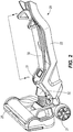
- the invention illustrated in the Figures and disclosed herein is generally directed to a vacuum cleaner 10, 10A having a vacuum component 20 that receives and carries a detachable hand vacuum 50.
- the hand vacuum 50 carries a hand vacuum battery 70 that provides power to operate only the hand vacuum 50 when detached from the vacuum component 20, and both the hand vacuum 50 and the vacuum component 20 when attached to the vacuum component 20.
- the battery 70 is removable from the hand vacuum 50 while the hand vacuum 50 remains attached to the vacuum component 20. Stated another way, the hand vacuum 50 does not have to be removed from the vacuum component 20 to remove the battery 70.
- the vacuum component 20 (or a portion of the vacuum component 20) defines an access aperture 40 that provides access to the battery 70.
- the battery 70 is removable from the hand vacuum 50 through the aperture 40 (or through the vacuum component 20), advantageously providing a user with fast, simple, and easy removal of the battery 70 from the vacuum cleaner 10, 10A. Once removed, the battery can be charged or recharged (i.e., the battery 70 is a rechargeable battery), or replaced. The battery 70 can also be attached (or reattached) to the hand vacuum 50 through the aperture 40 (or through the vacuum component 20).
- vacuum cleaner is inclusive, and refers to any vacuum that incorporates the removable battery innovation disclosed herein, including, but not limited to, a stick vacuum, an upright vacuum, a two-in-one vacuum, a canister vacuum, and/or a vacuum component that receives, attaches to, or otherwise connects to the hand vacuum 50.
- vacuum component 20 is illustrated as an upright or upright portion 20, the term "vacuum component” is inclusive, and refers to any component of a vacuum cleaner that incorporates the removable battery innovation disclosed herein.
- An example of a component of a vacuum can include, but is not limited to, an upright, a portion of a stick vacuum, a portion of a two-in-one vacuum, a portion of a canister vacuum, a crevice tool, and/or any other suitable components, accessories, or portion of a vacuum that receives, attaches to, or otherwise connects to the hand vacuum 50.
- the terms “upright” or “upright portion” are directed to a vacuum component that connects to the hand vacuum 50, and further may utilize a suction source 54 of the hand vacuum 50.
- the terms “upright” or “upright portion” as used herein are provided as a non-limiting example of a vacuum component.
- the upright portion 20 may include any suitable vacuum component that receives, attaches to, or otherwise connects to the hand vacuum 50, and further that may utilize the suction source 54 of the hand vacuum 50 to operate.
- dust is directed to dust, dirt, particulate, debris, or any other material that may be drawn into the vacuum cleaner 10 with air as dirty air.
- surface may include carpeting, flooring, concrete, or any other material from which the vacuum cleaner 10 may remove dust from.
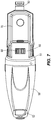
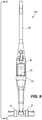
- FIGS. 1-7 illustrate an example of an embodiment of a vacuum cleaner 10.
- the vacuum cleaner 10 is shown as a multi-component vacuum 10 having a first component or first vacuum component or upright portion 20 and a second component or second vacuum component or hand vacuum 50.
- the hand vacuum 50 engages the upright portion 20 such that the hand vacuum 50 is in removable engagement with, removably received by, or removably coupled to the upright portion 20. Stated otherwise, the upright portion 20 receives and retains the hand vacuum 50 until the user disengages or removes the hand vacuum 50 from the upright portion 20.
- the vacuum cleaner 10 is operable in at least two cleaning modes.
- a user operates the vacuum cleaner 10 on a surface with the hand vacuum 50 in engagement with the upright portion 20.
- the hand vacuum 50 is detached from the upright portion 20.
- a user is then free to operate the hand vacuum 50 separately from the upright portion 20, for example to vacuum a targeted portion of the surface or to use with other accessories or vacuum components.
- the upright portion 20 includes a handle 22 having a first side 23 opposite a second side 24.
- the handle 22 is pivotally connected to a nozzle or floor engaging portion 25 to provide angle adjustment between the handle 22 and nozzle 25 during operation to maintain nozzle 25 contact with the surface being vacuumed.
- the nozzle 25 can include a pair of wheels 27 to facilitate movement of the nozzle 25 along the surface being vacuumed.
- the nozzle 25 includes a dirty air inlet 28 that can optionally carry an agitating unit 29.
- the agitating unit 29 can include a brush roll 29 or other suitable agitator. The brush roll 29 agitates the surface to facilitate dust removal from the surface.
- the brush roll 29 can be driven by a brush roll motor (not shown) in the floor engaging portion 25, can be driven by suction air flowing through a turbine (not shown), or can be free to rotate by suction air flowing through the dirty air inlet 28.
- the upright portion 20 further includes a power switch 26 that is operable to initiate or terminate operation of the vacuum 10.
- the power switch 26 is operably connected to the hand vacuum 50 to initiate or terminate operation of the hand vacuum 50 while attached to the upright portion 20.
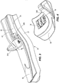
- the handle 22 of the illustrated embodiment includes a hand vacuum cradle 30 that is configured to receive and retain the hand vacuum 50 (shown in FIG. 1 ) with the upright portion 20.
- the cradle 30 includes a sealing surface 31 that forms a fluid connection between the nozzle 25 and a suction inlet 52 (shown in FIGS. 5-6 ) of the hand vacuum 50.
- the dirty air inlet 28 (shown in FIG. 1 ) of the nozzle 25 is in fluid connection with the sealing surface 31 by a conduit 32.
- the conduit 32 directs airflow from the dirty air inlet 28 of the floor engaging portion 25 to an attached hand vacuum 50.
- the sealing surface 31 can be any suitable surface to facilitate formation of a seal between the hand vacuum 50 suction inlet 52 and the upright portion 20.
- a portion of the sealing surface 31 can be received by the suction inlet 52 (as illustrated in FIG. 2 )
- a portion of the sealing surface 31 can receive a portion of a housing 51 of the hand vacuum 50 around the suction inlet 52, such as a portion of a dust cup 58 (as illustrated in FIG. 8 )
- a portion of the sealing surface 31 can engage a portion of a housing 51 that surrounds or is proximate to the suction inlet 52.
- the cradle 30 may include opposing retention members 34A, 34B that receive and stabilize the hand vacuum 50 when received by the cradle 30.
- the hand vacuum 50 is received between the opposing retention members 34A, 34B (see FIG. 1 ).
- the retention members 34A, 34B stabilize the hand vacuum 50, and assist against unintentional disengagement of the hand vacuum 50 from the upright portion 20.
- the upright portion or vacuum component 20 can receive power from the hand vacuum 50, such as for operating a brush roll motor (not shown) or other electric features.
- the cradle 30 of the illustrated embodiment includes a first electrical contact or contacts 36.
- the first electrical contact 36 engages a corresponding second electrical contact or contacts 66 positioned on the hand vacuum 50 (shown in FIG. 7 ).
- a projection or switch arm 38 on the upright portion 20, and more specifically the cradle 30 is configured to engage a switch 68 positioned on the hand vacuum 50 (shown in FIG. 7 ).
- the projection 38 engages the switch 68 to direct electricity from the battery 70 (carried by the hand vacuum 50), through the second electrical contact 66, and to the first electrical contact 36. From the first electrical contact 36, electricity is distributed to provide power to one or more electrical features in the vacuum component 20.
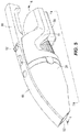
- the upright portion or vacuum component 20 defines an aperture 40.
- the aperture 40 extends between the first and second sides 23, 24 of the upright portion 20.
- a rim 42 can extend around a portion of a perimeter of the aperture 40.
- the aperture 40 can be positioned adjacent the cradle 30 such that when the hand vacuum 50 is received by the cradle 30, the battery 70 is positioned into alignment with aperture 40.
- a portion of the battery 70 can extend through aperture 40 (shown in FIG. 9 ). Stated another way, the aperture 40 can receive a portion of the battery 70.
- the battery 70 is accessible and removable through the upright portion 20 while the hand vacuum 50 remains attached to the upright portion 20.
- the hand vacuum 50 engages the upright portion 20.
- the battery 70 passes from the first side 23 of the upright portion 20, and into the aperture 40.
- the battery 70 is accessible and removable through the aperture 40 and out the second side 24 of the upright portion 20.
- the battery 70 is removable through the upright portion 20 (through the aperture 40) and out the second side 24 without requiring disengagement of the hand vacuum 50 from the upright portion 20.
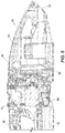
- the hand vacuum 50 includes a housing 51 that defines the hand vacuum 50.
- the suction inlet 52 provides access into the housing 51, and is in a fluid connection with (or fluidly connected to) a suction source 54 by a flow path.
- the suction source 54 is shown in FIG. 6 as a suction motor 54.
- a separator 56 shown in FIG. 6 , is disposed in the flow path between the suction inlet 52 and the suction motor 54.
- the separator 56 separates dust from dirty air drawn into the hand vacuum 50 through the suction inlet 52.
- the separated dust is retained in a dust cup 58 for collection and later disposal. To facilitate disposal, the dust cup 58 is removable from the hand vacuum 50.
- the separator 56 is shown as a cyclonic separator. However, in other embodiments, the separator 56 can be any suitable known or future developed device for separating dust from dirty air, including, but not limited to a filter, a bag, or other suitable separator for removing dust, dirt, or other particulates from air.
- the housing 51 includes a handle 60 to facilitate user operation of the hand vacuum 50.
- a power switch 62 is positioned on the housing 51 and in proximity to the handle 60 to allow a user to selectively turn on and off the hand vacuum 50.
- the removable battery 70 is also connected to the housing 51. As illustrated in FIGS. 5-7 , the battery 70 is positioned on the housing 51 opposite the handle 60. However in other embodiments, the battery 70 may be connected to the housing 51 at any suitable or desired location.
- FIGS. 8-10 illustrate an alternative embodiment of a vacuum cleaner 10A that incorporates the removable battery innovation disclosed herein.
- the vacuum cleaner 10A includes similar components as vacuum cleaner 10, with like numbers identifying like components.
- the user may operate the vacuum cleaner 10 in the first cleaning mode (or a first cleaning configuration) with the hand vacuum 50 attached to the upright portion 20, and the second cleaning mode (or a second cleaning configuration), with the hand vacuum 50 detached from the upright portion 20.
- the hand vacuum 50 is connected to the upright portion 20 (as shown in FIGS. 1 and 8 ).
- Operation of the vacuum cleaner 10 is then initiated, for example by actuation of the power switch 26 on the upright portion 20, or the power switch 62 on the hand vacuum 50.
- the nozzle can then be maneuvered along the floor or other surface as desired, for example through the handle 22.
- the hand vacuum 50 is detached from the upright portion 20.
- the hand vacuum 50 is removed from the cradle 30.
- the hand vacuum 50 can be powered on (e.g., by actuating the power switch 62).
- the hand vacuum 50 can be used to vacuum a surface by grasping the hand vacuum 50 (e.g., by the handle 60).
- the hand vacuum 50 can be reengaged with the upright portion 20.
- the hand vacuum 50 is positioned in the cradle 30.
- the battery 70 can be aligned with the aperture 40.
- the cradle 30 receives the hand vacuum 50, and the aperture 40 can receive a portion of the battery 70.
- the battery 70 can be removed from the hand vacuum 50 without requiring disengagement of the hand vacuum 50 from the upright portion 20.
- a user has access to the battery 70 through the aperture 40 defined by the upright portion 20 (or a portion of the upright portion 20). The access allows the user to disconnect the battery 70 from the hand vacuum 50 and remove the battery through the aperture 40.
- the battery 70 is removable from the hand vacuum 50 through the upright portion 20, while the hand vacuum 50 remains connected to (or engaged with or received by) the upright portion 20. It should be appreciated that the battery 70 is also removable from the hand vacuum 50 when the hand vacuum 50 is disconnected from (or disengaged with) the upright portion 20.
- the vacuum cleaner 10, 10A advantageously provides a user with a fast, simple, and easily removable battery 70. This improves the user experience associated with the vacuum cleaner 10, 10A, as the battery 70 is removed in fewer steps than known hand vacuums that engage and power vacuum components, such as the upright portion 20. These and other advantages may be realized from one or more embodiments of the vacuum cleaner 10, 10A disclosed herein.
Applications Claiming Priority (2)
| Application Number | Priority Date | Filing Date | Title |
|---|---|---|---|
| US201462064864P | 2014-10-16 | 2014-10-16 | |
| PCT/US2015/056046 WO2016061521A1 (en) | 2014-10-16 | 2015-10-16 | Improved battery removal for a vacuum cleaner |
Publications (2)
| Publication Number | Publication Date |
|---|---|
| EP3206545A1 EP3206545A1 (en) | 2017-08-23 |
| EP3206545B1 true EP3206545B1 (en) | 2021-09-29 |
Family
ID=54361204
Family Applications (1)
| Application Number | Title | Priority Date | Filing Date |
|---|---|---|---|
| EP15787403.3A Active EP3206545B1 (en) | 2014-10-16 | 2015-10-16 | Improved battery removal for a vacuum cleaner |
Country Status (5)
| Country | Link |
|---|---|
| US (3) | US9439548B2 (ko) |
| EP (1) | EP3206545B1 (ko) |
| KR (1) | KR102386267B1 (ko) |
| CN (1) | CN107072452B (ko) |
| WO (1) | WO2016061521A1 (ko) |
Families Citing this family (32)
| Publication number | Priority date | Publication date | Assignee | Title |
|---|---|---|---|---|
| US10722086B2 (en) | 2017-07-06 | 2020-07-28 | Omachron Intellectual Property Inc. | Handheld surface cleaning apparatus |
| CN107072452B (zh) | 2014-10-16 | 2019-08-30 | 创科实业有限公司 | 真空吸尘器以及从真空吸尘器中移除电池的方法 |
| EP3238588A4 (en) * | 2016-01-20 | 2018-05-30 | Jiangsu Midea Cleaning Appliances Co., Ltd. | Vacuum cleaner |
| CA2971319A1 (en) * | 2016-01-20 | 2017-07-27 | Jiangsu Midea Cleaning Appliances Co., Ltd. | Vacuum cleaner |
| CA2971069A1 (en) * | 2016-01-20 | 2017-07-20 | Jiangsu Midea Cleaning Appliances Co., Ltd. | Vacuum cleaner |
| WO2017124628A1 (zh) * | 2016-01-20 | 2017-07-27 | 江苏美的清洁电器股份有限公司 | 手持式吸尘器 |
| CA2971067A1 (en) * | 2016-01-20 | 2017-07-20 | Jiangsu Midea Cleaning Appliances Co., Ltd. | Vacuum cleaner |
| CA169997S (en) | 2016-08-17 | 2017-03-24 | Canadian Tire Corp Ltd | Blower nozzle |
| US11337570B2 (en) * | 2016-10-07 | 2022-05-24 | Aktiebolaget Electrolux | Stick vacuum cleaner with improved filter |
| KR20190064581A (ko) * | 2016-10-07 | 2019-06-10 | 에이비 엘렉트로룩스 | 저소음 막대형 진공 청소기 |
| DE102017209152A1 (de) * | 2017-05-31 | 2018-12-06 | BSH Hausgeräte GmbH | Bequem wiederaufladbarer in der Hand gehaltener akkubetriebener Staubsauger |
| USD836863S1 (en) | 2017-06-12 | 2018-12-25 | Emerson Electric Co. | Upright vacuum cleaner |
| US10758101B2 (en) | 2017-06-12 | 2020-09-01 | Emerson Electric Co. | Upright vacuum cleaner with battery support plate |
| US10750913B2 (en) | 2017-07-06 | 2020-08-25 | Omachron Intellectual Property Inc. | Handheld surface cleaning apparatus |
| US10506904B2 (en) | 2017-07-06 | 2019-12-17 | Omachron Intellectual Property Inc. | Handheld surface cleaning apparatus |
| US10537216B2 (en) | 2017-07-06 | 2020-01-21 | Omachron Intellectual Property Inc. | Handheld surface cleaning apparatus |
| US10842330B2 (en) | 2017-07-06 | 2020-11-24 | Omachron Intellectual Property Inc. | Handheld surface cleaning apparatus |
| US10631693B2 (en) * | 2017-07-06 | 2020-04-28 | Omachron Intellectual Property Inc. | Handheld surface cleaning apparatus |
| US10702113B2 (en) | 2017-07-06 | 2020-07-07 | Omachron Intellectual Property Inc. | Handheld surface cleaning apparatus |
| USD897059S1 (en) * | 2017-10-20 | 2020-09-22 | Shenzhen Hizero Technologies Co., Ltd. | Floor cleaner |
| JP1624324S (ko) * | 2018-04-11 | 2019-02-12 | ||
| CN110367873B (zh) * | 2018-04-13 | 2021-05-28 | 添可电器有限公司 | 多电源分体式吸尘器及其供电方法 |
| USD876736S1 (en) * | 2018-04-30 | 2020-02-25 | Toshiba Lifestyle Products & Services Corporation | Vacuum cleaner |
| USD869798S1 (en) * | 2018-06-28 | 2019-12-10 | Shenzhen Haohongyuan Technology Co., Ltd. | Vacuum cleaner |
| CN108968797B (zh) * | 2018-07-10 | 2021-10-01 | 江苏美的清洁电器股份有限公司 | 清洁设备 |
| US11154169B2 (en) | 2018-08-13 | 2021-10-26 | Omachron Intellectual Property Inc. | Cyclonic air treatment member and surface cleaning apparatus including the same |
| DE212019000449U1 (de) * | 2018-12-13 | 2021-07-21 | Koki Holdings Co., Ltd. | Reiniger |
| USD937513S1 (en) | 2019-09-16 | 2021-11-30 | Techtronic Cordless Gp | Floor cleaner |
| WO2021138122A1 (en) | 2020-01-03 | 2021-07-08 | Techtronic Cordless Gp | Adapter for vacuum cleaner assembly |
| CN112369959A (zh) * | 2020-10-14 | 2021-02-19 | 添可智能科技有限公司 | 清洁设备 |
| WO2022147300A1 (en) | 2020-12-30 | 2022-07-07 | Milwaukee Electric Tool Corporation | Handheld blower |
| USD1017156S1 (en) | 2022-05-09 | 2024-03-05 | Dupray Ventures Inc. | Cleaner |
Family Cites Families (29)
| Publication number | Priority date | Publication date | Assignee | Title |
|---|---|---|---|---|
| GB2269475B (en) | 1992-08-06 | 1996-05-01 | Gsl Rechargeable Products Limi | Battery operated electrical device |
| US5709007A (en) * | 1996-06-10 | 1998-01-20 | Chiang; Wayne | Remote control vacuum cleaner |
| KR200184974Y1 (ko) * | 1997-11-06 | 2000-06-15 | 주영종 | 스탠드형 및 휴대형 겸용 진공청소기 |
| GB2377880A (en) | 2001-07-25 | 2003-01-29 | Black & Decker Inc | Multi-operational battery powered vacuum cleaner |
| SE0300355D0 (sv) | 2003-02-10 | 2003-02-10 | Electrolux Ab | Hand held vacuum cleaner |
| US20070136984A1 (en) | 2005-12-15 | 2007-06-21 | Zweita International Co., Ltd. | Rechargeable vacuum cleaner |
| SE531125C2 (sv) * | 2007-01-19 | 2008-12-23 | Electrolux Ab | Förbättringar med avseende på luftströmningsförluster i en dammsugare |
| US20080040883A1 (en) | 2006-04-10 | 2008-02-21 | Jonas Beskow | Air Flow Losses in a Vacuum Cleaners |
| CN101460083B (zh) | 2006-04-10 | 2014-08-13 | 伊莱克斯公司 | 真空吸尘器 |
| EP2007264B1 (en) | 2006-04-10 | 2019-03-13 | Aktiebolaget Electrolux | Vacuum cleaner with filter cleaning means |
| KR100730955B1 (ko) * | 2006-04-27 | 2007-06-22 | 주식회사 대우일렉트로닉스 | 진공 청소기 |
| WO2008054182A1 (en) * | 2006-11-03 | 2008-05-08 | Daewoo Electronics Corporation | Method for vacuum cleaning |
| KR100762323B1 (ko) * | 2006-11-03 | 2007-10-02 | 주식회사 대우일렉트로닉스 | 핸디청소기 일체형 진공청소기 |
| TWM325088U (en) * | 2007-08-15 | 2008-01-11 | Ling-Chu Su | Three level separable wireless vacuum |
| KR200450573Y1 (ko) * | 2007-08-15 | 2010-10-13 | 링-추 수 | 분리가능한 배터리 구동 진공청소기 |
| EP2258011B1 (en) * | 2008-03-14 | 2015-12-02 | Royal Appliance Mfg. Co. | Removable battery pack with latching mechanism |
| USD615717S1 (en) | 2008-10-16 | 2010-05-11 | Techtronic Floor Care Technology Limited | Portable cleaning device with handle |
| USD652377S1 (en) | 2008-10-16 | 2012-01-17 | Techtronic Floor Care Technology Limited | Battery charger combination |
| US8607405B2 (en) | 2008-03-14 | 2013-12-17 | Techtronic Floor Care Technology Limited | Battery powered cordless cleaning system |
| US20090255084A1 (en) * | 2008-03-14 | 2009-10-15 | Gee Ii Jack W | Removable Battery Pack with Latching Mechanism |
| CN102245071B (zh) * | 2008-10-10 | 2014-05-28 | 伊莱克斯公司 | 真空吸尘器出气口 |
| USD620652S1 (en) | 2008-10-16 | 2010-07-27 | Techtronic Floor Care Technology Limited | Portable hand held cleaning device |
| US20100192314A1 (en) | 2009-02-03 | 2010-08-05 | Makita Corporation | Handy cleaners |
| US10517449B2 (en) | 2010-05-31 | 2019-12-31 | Samsung Electronics Co., Ltd. | Cyclone dust collecting apparatus and hand-held cleaner having the same |
| US8671510B2 (en) | 2010-05-31 | 2014-03-18 | Samsung Electronics Co., Ltd. | Hand-held and stick vacuum cleaner |
| DE102012206624A1 (de) | 2012-04-23 | 2013-10-24 | Robert Bosch Gmbh | System mit einem Bodenstaubsauger und einem Handstaubsauger |
| CN203169087U (zh) * | 2012-11-16 | 2013-09-04 | 杨颂凯 | 一种结构改良的吸尘器 |
| JP2014176567A (ja) * | 2013-03-15 | 2014-09-25 | Makita Corp | クリーナ |
| CN107072452B (zh) * | 2014-10-16 | 2019-08-30 | 创科实业有限公司 | 真空吸尘器以及从真空吸尘器中移除电池的方法 |
-
2015
- 2015-10-16 CN CN201580057383.9A patent/CN107072452B/zh active Active
- 2015-10-16 WO PCT/US2015/056046 patent/WO2016061521A1/en active Application Filing
- 2015-10-16 EP EP15787403.3A patent/EP3206545B1/en active Active
- 2015-10-16 KR KR1020177012696A patent/KR102386267B1/ko active IP Right Grant
- 2015-10-16 US US14/885,717 patent/US9439548B2/en active Active
-
2016
- 2016-08-17 US US15/238,806 patent/US9861240B2/en active Active
-
2017
- 2017-12-20 US US15/849,101 patent/US10213074B2/en active Active
Also Published As
| Publication number | Publication date |
|---|---|
| US20160106285A1 (en) | 2016-04-21 |
| CN107072452A (zh) | 2017-08-18 |
| EP3206545A1 (en) | 2017-08-23 |
| KR20170070128A (ko) | 2017-06-21 |
| US9861240B2 (en) | 2018-01-09 |
| US20160353952A1 (en) | 2016-12-08 |
| US10213074B2 (en) | 2019-02-26 |
| KR102386267B1 (ko) | 2022-04-13 |
| CN107072452B (zh) | 2019-08-30 |
| US20180110383A1 (en) | 2018-04-26 |
| US9439548B2 (en) | 2016-09-13 |
| WO2016061521A1 (en) | 2016-04-21 |
Similar Documents
| Publication | Publication Date | Title |
|---|---|---|
| EP3206545B1 (en) | Improved battery removal for a vacuum cleaner | |
| US10980378B2 (en) | Cleaning device | |
| KR100730952B1 (ko) | 핸디청소기 일체형 진공청소기 | |
| EP2988641B1 (en) | Vacuum cleaner including a removable dirt collection assembly | |
| KR100730955B1 (ko) | 진공 청소기 | |
| CN110996739B (zh) | 表面清洁设备 | |
| US20200367706A1 (en) | Cleaning device | |
| WO2016094486A1 (en) | Battery powered vacuum cleaner | |
| JP2019217209A (ja) | 電気掃除機 |
Legal Events
| Date | Code | Title | Description |
|---|---|---|---|
| STAA | Information on the status of an ep patent application or granted ep patent |
Free format text: STATUS: THE INTERNATIONAL PUBLICATION HAS BEEN MADE |
|
| PUAI | Public reference made under article 153(3) epc to a published international application that has entered the european phase |
Free format text: ORIGINAL CODE: 0009012 |
|
| STAA | Information on the status of an ep patent application or granted ep patent |
Free format text: STATUS: REQUEST FOR EXAMINATION WAS MADE |
|
| 17P | Request for examination filed |
Effective date: 20170425 |
|
| AK | Designated contracting states |
Kind code of ref document: A1 Designated state(s): AL AT BE BG CH CY CZ DE DK EE ES FI FR GB GR HR HU IE IS IT LI LT LU LV MC MK MT NL NO PL PT RO RS SE SI SK SM TR |
|
| AX | Request for extension of the european patent |
Extension state: BA ME |
|
| DAV | Request for validation of the european patent (deleted) | ||
| DAX | Request for extension of the european patent (deleted) | ||
| GRAP | Despatch of communication of intention to grant a patent |
Free format text: ORIGINAL CODE: EPIDOSNIGR1 |
|
| STAA | Information on the status of an ep patent application or granted ep patent |
Free format text: STATUS: GRANT OF PATENT IS INTENDED |
|
| INTG | Intention to grant announced |
Effective date: 20210428 |
|
| GRAS | Grant fee paid |
Free format text: ORIGINAL CODE: EPIDOSNIGR3 |
|
| GRAA | (expected) grant |
Free format text: ORIGINAL CODE: 0009210 |
|
| STAA | Information on the status of an ep patent application or granted ep patent |
Free format text: STATUS: THE PATENT HAS BEEN GRANTED |
|
| AK | Designated contracting states |
Kind code of ref document: B1 Designated state(s): AL AT BE BG CH CY CZ DE DK EE ES FI FR GB GR HR HU IE IS IT LI LT LU LV MC MK MT NL NO PL PT RO RS SE SI SK SM TR |
|
| REG | Reference to a national code |
Ref country code: GB Ref legal event code: FG4D |
|
| REG | Reference to a national code |
Ref country code: CH Ref legal event code: EP Ref country code: AT Ref legal event code: REF Ref document number: 1433489 Country of ref document: AT Kind code of ref document: T Effective date: 20211015 |
|
| REG | Reference to a national code |
Ref country code: DE Ref legal event code: R096 Ref document number: 602015073715 Country of ref document: DE |
|
| REG | Reference to a national code |
Ref country code: IE Ref legal event code: FG4D |
|
| REG | Reference to a national code |
Ref country code: LT Ref legal event code: MG9D |
|
| PG25 | Lapsed in a contracting state [announced via postgrant information from national office to epo] |
Ref country code: HR Free format text: LAPSE BECAUSE OF FAILURE TO SUBMIT A TRANSLATION OF THE DESCRIPTION OR TO PAY THE FEE WITHIN THE PRESCRIBED TIME-LIMIT Effective date: 20210929 Ref country code: RS Free format text: LAPSE BECAUSE OF FAILURE TO SUBMIT A TRANSLATION OF THE DESCRIPTION OR TO PAY THE FEE WITHIN THE PRESCRIBED TIME-LIMIT Effective date: 20210929 Ref country code: SE Free format text: LAPSE BECAUSE OF FAILURE TO SUBMIT A TRANSLATION OF THE DESCRIPTION OR TO PAY THE FEE WITHIN THE PRESCRIBED TIME-LIMIT Effective date: 20210929 Ref country code: LT Free format text: LAPSE BECAUSE OF FAILURE TO SUBMIT A TRANSLATION OF THE DESCRIPTION OR TO PAY THE FEE WITHIN THE PRESCRIBED TIME-LIMIT Effective date: 20210929 Ref country code: BG Free format text: LAPSE BECAUSE OF FAILURE TO SUBMIT A TRANSLATION OF THE DESCRIPTION OR TO PAY THE FEE WITHIN THE PRESCRIBED TIME-LIMIT Effective date: 20211229 Ref country code: NO Free format text: LAPSE BECAUSE OF FAILURE TO SUBMIT A TRANSLATION OF THE DESCRIPTION OR TO PAY THE FEE WITHIN THE PRESCRIBED TIME-LIMIT Effective date: 20211229 Ref country code: FI Free format text: LAPSE BECAUSE OF FAILURE TO SUBMIT A TRANSLATION OF THE DESCRIPTION OR TO PAY THE FEE WITHIN THE PRESCRIBED TIME-LIMIT Effective date: 20210929 |
|
| REG | Reference to a national code |
Ref country code: NL Ref legal event code: MP Effective date: 20210929 |
|
| REG | Reference to a national code |
Ref country code: AT Ref legal event code: MK05 Ref document number: 1433489 Country of ref document: AT Kind code of ref document: T Effective date: 20210929 |
|
| PG25 | Lapsed in a contracting state [announced via postgrant information from national office to epo] |
Ref country code: LV Free format text: LAPSE BECAUSE OF FAILURE TO SUBMIT A TRANSLATION OF THE DESCRIPTION OR TO PAY THE FEE WITHIN THE PRESCRIBED TIME-LIMIT Effective date: 20210929 Ref country code: GR Free format text: LAPSE BECAUSE OF FAILURE TO SUBMIT A TRANSLATION OF THE DESCRIPTION OR TO PAY THE FEE WITHIN THE PRESCRIBED TIME-LIMIT Effective date: 20211230 |
|
| PG25 | Lapsed in a contracting state [announced via postgrant information from national office to epo] |
Ref country code: AT Free format text: LAPSE BECAUSE OF FAILURE TO SUBMIT A TRANSLATION OF THE DESCRIPTION OR TO PAY THE FEE WITHIN THE PRESCRIBED TIME-LIMIT Effective date: 20210929 |
|
| REG | Reference to a national code |
Ref country code: CH Ref legal event code: PL |
|
| PG25 | Lapsed in a contracting state [announced via postgrant information from national office to epo] |
Ref country code: IS Free format text: LAPSE BECAUSE OF FAILURE TO SUBMIT A TRANSLATION OF THE DESCRIPTION OR TO PAY THE FEE WITHIN THE PRESCRIBED TIME-LIMIT Effective date: 20220129 Ref country code: SK Free format text: LAPSE BECAUSE OF FAILURE TO SUBMIT A TRANSLATION OF THE DESCRIPTION OR TO PAY THE FEE WITHIN THE PRESCRIBED TIME-LIMIT Effective date: 20210929 Ref country code: RO Free format text: LAPSE BECAUSE OF FAILURE TO SUBMIT A TRANSLATION OF THE DESCRIPTION OR TO PAY THE FEE WITHIN THE PRESCRIBED TIME-LIMIT Effective date: 20210929 Ref country code: PT Free format text: LAPSE BECAUSE OF FAILURE TO SUBMIT A TRANSLATION OF THE DESCRIPTION OR TO PAY THE FEE WITHIN THE PRESCRIBED TIME-LIMIT Effective date: 20220131 Ref country code: PL Free format text: LAPSE BECAUSE OF FAILURE TO SUBMIT A TRANSLATION OF THE DESCRIPTION OR TO PAY THE FEE WITHIN THE PRESCRIBED TIME-LIMIT Effective date: 20210929 Ref country code: NL Free format text: LAPSE BECAUSE OF FAILURE TO SUBMIT A TRANSLATION OF THE DESCRIPTION OR TO PAY THE FEE WITHIN THE PRESCRIBED TIME-LIMIT Effective date: 20210929 Ref country code: ES Free format text: LAPSE BECAUSE OF FAILURE TO SUBMIT A TRANSLATION OF THE DESCRIPTION OR TO PAY THE FEE WITHIN THE PRESCRIBED TIME-LIMIT Effective date: 20210929 Ref country code: EE Free format text: LAPSE BECAUSE OF FAILURE TO SUBMIT A TRANSLATION OF THE DESCRIPTION OR TO PAY THE FEE WITHIN THE PRESCRIBED TIME-LIMIT Effective date: 20210929 Ref country code: CZ Free format text: LAPSE BECAUSE OF FAILURE TO SUBMIT A TRANSLATION OF THE DESCRIPTION OR TO PAY THE FEE WITHIN THE PRESCRIBED TIME-LIMIT Effective date: 20210929 Ref country code: AL Free format text: LAPSE BECAUSE OF FAILURE TO SUBMIT A TRANSLATION OF THE DESCRIPTION OR TO PAY THE FEE WITHIN THE PRESCRIBED TIME-LIMIT Effective date: 20210929 |
|
| REG | Reference to a national code |
Ref country code: BE Ref legal event code: MM Effective date: 20211031 |
|
| PG25 | Lapsed in a contracting state [announced via postgrant information from national office to epo] |
Ref country code: MC Free format text: LAPSE BECAUSE OF FAILURE TO SUBMIT A TRANSLATION OF THE DESCRIPTION OR TO PAY THE FEE WITHIN THE PRESCRIBED TIME-LIMIT Effective date: 20210929 |
|
| REG | Reference to a national code |
Ref country code: DE Ref legal event code: R097 Ref document number: 602015073715 Country of ref document: DE |
|
| PG25 | Lapsed in a contracting state [announced via postgrant information from national office to epo] |
Ref country code: LU Free format text: LAPSE BECAUSE OF NON-PAYMENT OF DUE FEES Effective date: 20211016 Ref country code: DK Free format text: LAPSE BECAUSE OF FAILURE TO SUBMIT A TRANSLATION OF THE DESCRIPTION OR TO PAY THE FEE WITHIN THE PRESCRIBED TIME-LIMIT Effective date: 20210929 Ref country code: BE Free format text: LAPSE BECAUSE OF NON-PAYMENT OF DUE FEES Effective date: 20211031 |
|
| PLBE | No opposition filed within time limit |
Free format text: ORIGINAL CODE: 0009261 |
|
| STAA | Information on the status of an ep patent application or granted ep patent |
Free format text: STATUS: NO OPPOSITION FILED WITHIN TIME LIMIT |
|
| PG25 | Lapsed in a contracting state [announced via postgrant information from national office to epo] |
Ref country code: LI Free format text: LAPSE BECAUSE OF NON-PAYMENT OF DUE FEES Effective date: 20211031 Ref country code: CH Free format text: LAPSE BECAUSE OF NON-PAYMENT OF DUE FEES Effective date: 20211031 |
|
| 26N | No opposition filed |
Effective date: 20220630 |
|
| PG25 | Lapsed in a contracting state [announced via postgrant information from national office to epo] |
Ref country code: IE Free format text: LAPSE BECAUSE OF NON-PAYMENT OF DUE FEES Effective date: 20211016 |
|
| PG25 | Lapsed in a contracting state [announced via postgrant information from national office to epo] |
Ref country code: SI Free format text: LAPSE BECAUSE OF FAILURE TO SUBMIT A TRANSLATION OF THE DESCRIPTION OR TO PAY THE FEE WITHIN THE PRESCRIBED TIME-LIMIT Effective date: 20210929 |
|
| PGFP | Annual fee paid to national office [announced via postgrant information from national office to epo] |
Ref country code: FR Payment date: 20221025 Year of fee payment: 8 |
|
| PG25 | Lapsed in a contracting state [announced via postgrant information from national office to epo] |
Ref country code: IT Free format text: LAPSE BECAUSE OF FAILURE TO SUBMIT A TRANSLATION OF THE DESCRIPTION OR TO PAY THE FEE WITHIN THE PRESCRIBED TIME-LIMIT Effective date: 20210929 |
|
| PGFP | Annual fee paid to national office [announced via postgrant information from national office to epo] |
Ref country code: GB Payment date: 20221027 Year of fee payment: 8 Ref country code: DE Payment date: 20221027 Year of fee payment: 8 |
|
| PG25 | Lapsed in a contracting state [announced via postgrant information from national office to epo] |
Ref country code: HU Free format text: LAPSE BECAUSE OF FAILURE TO SUBMIT A TRANSLATION OF THE DESCRIPTION OR TO PAY THE FEE WITHIN THE PRESCRIBED TIME-LIMIT; INVALID AB INITIO Effective date: 20151016 |
|
| PG25 | Lapsed in a contracting state [announced via postgrant information from national office to epo] |
Ref country code: CY Free format text: LAPSE BECAUSE OF FAILURE TO SUBMIT A TRANSLATION OF THE DESCRIPTION OR TO PAY THE FEE WITHIN THE PRESCRIBED TIME-LIMIT Effective date: 20210929 |
|
| PG25 | Lapsed in a contracting state [announced via postgrant information from national office to epo] |
Ref country code: SM Free format text: LAPSE BECAUSE OF FAILURE TO SUBMIT A TRANSLATION OF THE DESCRIPTION OR TO PAY THE FEE WITHIN THE PRESCRIBED TIME-LIMIT Effective date: 20210929 |
|
| PG25 | Lapsed in a contracting state [announced via postgrant information from national office to epo] |
Ref country code: MK Free format text: LAPSE BECAUSE OF FAILURE TO SUBMIT A TRANSLATION OF THE DESCRIPTION OR TO PAY THE FEE WITHIN THE PRESCRIBED TIME-LIMIT Effective date: 20210929 |